Acura RL (1996-2004 year). Manual - part 644


  Index      Acura     Acura RL 1996-2004 year - service repair manual


Search            


Content   ..  642  643  644  645   ..


Acura RL (1996-2004 year). Manual - part 644


Multiplex Control System

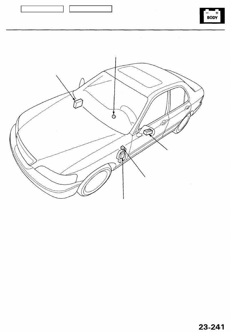
Component Location Index

IGNITION KEY LIGHT
Replacement, page 

23-254

MULTIPLEX CONTROL UNIT (PASSENGER'S)
(Has built-in the beeper)

MULTIPLEX CONTROL UNIT (DOOR)
(built into the power window
master switch)

MULTIPLEX CONTROL
INSPECTION CONNECTOR
[Wire color: PNK/BLK and BLK]

MULTIPLEX CONTROL UNIT (DRIVER'S)

Description

The multiplex control system is composed of three control units (located in the driver's side kick panel, passenger's side

kick panel, and driver's door).

These three control units send multiplex signals over shared wires,reduce the number of control units and wire harness
weight, and improves the quality of electrical functions by means of the integrated circuits. This system has a built-in self-
diagnosis function.

Main Menu

Table of Contents

System Functions

• Multiplex Control System (Multiplex function, Wake up/sleep function, Fail-safe function, Self-diagnosis function*)

*: Self-diagnosis function mode 1 is the self-diagnosis for the multiplex control system.

Self-diagnosis function mode 2 is the failure diagnosis for the input line of each system.

• Integrated Control System (Engine oil pressure indicator flasher circuit, Key-in reminder circuit, Light-on reminder circuit,

Seat belt reminder circuit)

• Dash Lights Brightness Control
• Entry Light Control System
• Rear Window Defogger
• Trunk lid Opener
• Power Door Locks (with keyless entry system)
• Power Window (with key-off timer operation)
• Wiper/washers (with speed respondent intermittent wiper)
• Security Alarm System
• Interlock System (see 

section 14

)

Multiplex Communication System

Multiplex Communication Functions

• To reduce the number of wire harnesses, digital signals are sent via shared multiplex communication lines rather than

sending normal electrical signals through individual wires.

• The input signals from each switch are converted to digital signals at the central processing unit (CPU). The digital

signals are sent from the transmitter unit to the receiver unit as serial signals.

• The transmitted signal is converted to a switch signal at the receiver unit, and it operates the related component.
• There are exclusive communication lines between each of the multiplex control units:

Door Driver's (from the door to the driver's multiplex control units) Wire color: BRN/YEL

Driver's Passenger's (from the driver's to the passenger's multiplex control units) Wire color: BRN/WHT

Passenger's Driver's (from the passenger's to the driver's multiplex control units) Wire color: RED/YEL

• The control units always communicate via these lines when the system is operating, and they stop communicating

when the system is OFF.

Wake-up and Sleep Functions

• The multiplex control system has "wake-up" and "sleep" functions to decrease parasitic draw on the battery when the

ignition switch is OFF.

• In the sleep mode, the multiplex control unit stops the functions (communication and CPU control) when it is not nec-

essary for the system to operate.

• As soon as any operation is done (for example, a door is unlocked), the related control unit in the sleep mode wakes up

and begins to function at once. This control unit also sends a wake-up signal to the other control units via the commu-

nication lines.

• When the ignition switch is turned OFF, there is about a 30 second delay before the control units go from the wake-up

mode to the sleep mode.

• If any door is open, the sleep mode will not function.

Fail-safe Functions

• To prevent improper operation, the multiplex control system has a fail-safe function. In the fail-safe mode, the output

signal is fixed when any part of the system malfunctions (for example, a faulty control unit or communication line).

• Each control unit has a hardware fail-safe function that fixes the output signal when there is any CPU malfunction and

a software fail-safe function that ignores the signal from the malfunctioning control unit and allows the system to
operate normally.

Main Menu

Table of Contents

Multiplex Control System

Troubleshooting Guide

A problem has been detected
with at least one of the multiplex
control system functions.

Check the No. 13, 17, 44, and 56
fuses.

Are the fuses OK? 

Find and repair cause of the
blown fuse.

NO

YES

Check the power and ground sys-
tem (see pag

23-245

).

Is the power and ground
system OK?

Repair the power and ground
system.

NO

YES

Check the self-diagnosis function
(Mode 1) for a diagnostic trouble
code (DTC) (see page 

23-248

).

Find and repair the cause of the
DTC.

YES

Is a DTC indicated?

NO

Check the wake-up function (see
page 

23-249

).

NO

Repair the wake-up function.

Is the wake-up function OK?

YES

Troubleshoot the individual sys-
tem function that had a problem.

Main Menu

Table of Contents

Power and Ground Test

Multiplex Control Unit (Door):

1. Remove the driver's door panel, and disconnect the 20P connector from the door unit.

2. Inspect the connector and socket terminals to be sure they are all making good contact.

• If the terminals are bent, loose or corroded, repair them as necessary, and recheck the system.
• If the terminals look OK, make the following input tests at the connector.

If a test indicates a problem, find and correct the cause, then recheck the system.
If all the input tests prove OK, the power window master switch must be faulty; replace it.

MULTIPLEX CONTROL UNIT (DOOR)

DRIVER'S
DOOR
PANEL

2OP

CONNECTOR

Wire side of
female terminals

WHT/YEL

GRN/WHT*

1

WHT/BLK*

2

BLK

BLK*

1

Cavity Wire Test condition Test: Desired result Possible cause if result is not obtained

WHT/YEL

GRN/WHT

or

WHT/BLK

BLK

Under all conditions

Ignition switch ON (II)

Under all conditions

Check for voltage to ground:
There should be battery voltage.

Check for voltage to ground:
There should be battery voltage.

Check for continuity to ground:
There should be continuity.

• Blown No. 56 (7.5 A) fuse in the

under-hood fuse/relay box

• An open in the wire

• Blown No. 17 (20 A)*

1

 or No. 17

(7.5 A)*

2

 fuse in the under-dash

fuse/relay box

• Faulty power window relay
• An open in the wire

• Poor ground (G401, G402)
• An open in the wire

*1: '96 -97 models
*2: '98 - 00 models

Main Menu

Table of Contents


Content   ..  642  643  644  645   ..