Acura RL (1996-2004 year). Manual - part 536
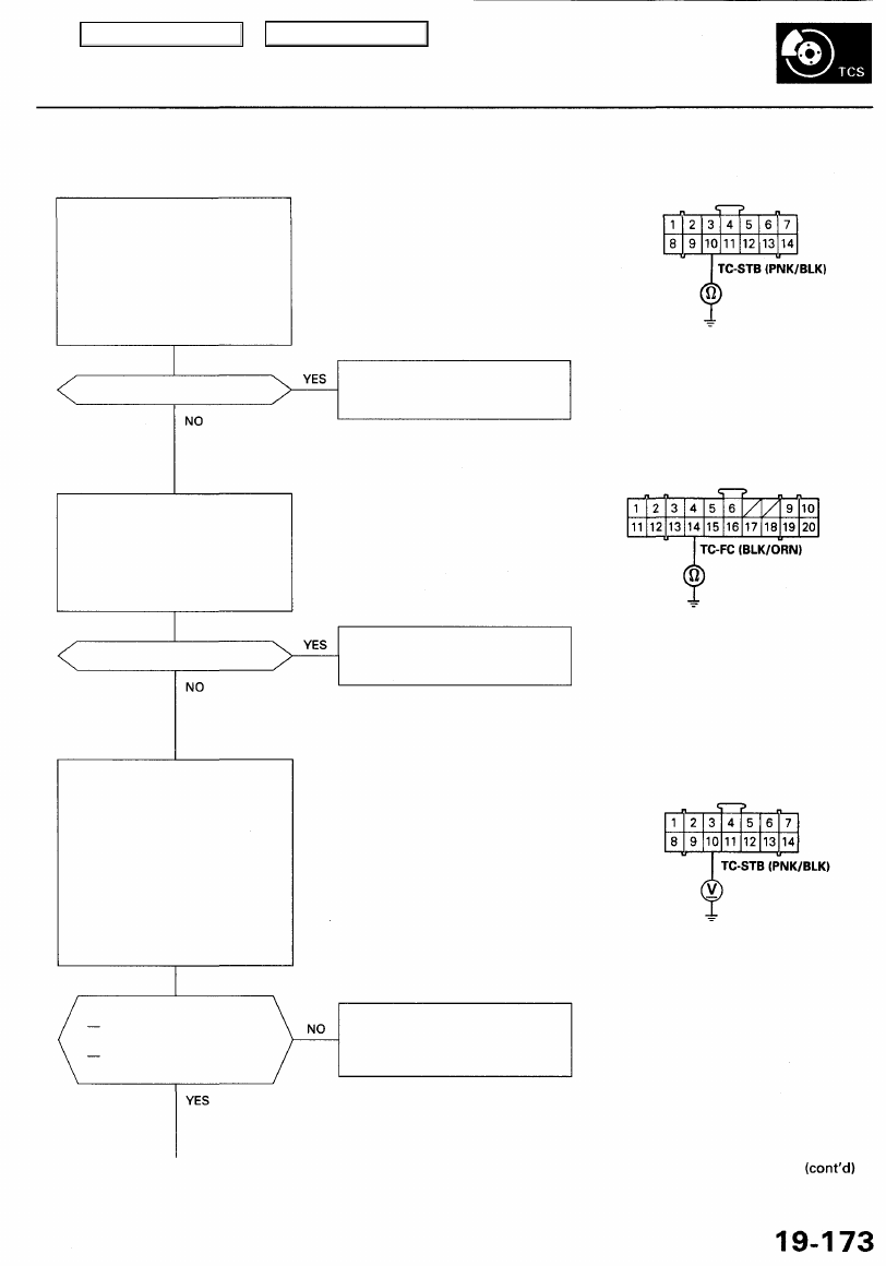
PGM-FI DTC: 35 (TC-STB signal does not match TC-FC signal)
Check for a short to body ground
in the TC-STB circuit:
1. Disconnect the PCM connec-
tor C (12P) and TCS control
unit 14P connectors.
2. Check for continuity between
the TCS control unit UP con-
nector terminal No. 10 and
body ground.
TCS CONTROL UNIT 14P CONNECTOR
Wire side of female terminals
Is there continuity?
Repair short to body ground in
the wire between the PCM and
TCS control unit.
TCS CONTROL UNIT 20P CONNECTOR
Check for a short to body ground
in the TC-FC circuit:
1. Disconnect the TCS control
unit 20P connector.
2. Check for continuity between
terminal No. 14 and body
ground.
Is there continuity?
Repair short to body ground in
the wire between the PCM and
TCS control unit.
Wire side of female terminals
Check the TCS control unit (TC-
STB):
1. Connect the TCS control unit
14P and 20P connectors and
PCM connector C (12P).
2. Raise the front of the vehicle,
and support it with safety
stands.
3. Start the engine.
4. Measure the voltage between
the TCS control unit 14P con-
nector terminal No. 10 and
body ground.
TCS CONTROL UNIT UP CONNECTOR
Wire side of female terminals
Is the voltage as specified?
TCS is functioning:
about 0 V
TCS is not functioning:
about 5 V
Check for loose TCS control unit
connectors. If necessary, substi-
tute a known-good TCS control
unit and recheck.
NOTE: Stop the wheels by depressing
the brake pedal lightly.
Main Menu
Table of Contents