Acura RL (1996-2004 year). Manual - part 534


  Index      Acura     Acura RL 1996-2004 year - service repair manual


Search            


Content   ..  532  533  534  535   ..


Acura RL (1996-2004 year). Manual - part 534


Parking Brake

Diagnostic Trouble Code (DTC) 2: Parking Brake Diagnosis

When the rear wheel speed is 6 mph (10 km/h) or more and the parking brake is applied for more than 30 seconds continu-

ously, the TCS control unit causes the TCS indicator light to come on.

Does the brake system light

come on? 

To page 

19-166

Is the bulb OK?

Replace the brake system light
bulb.

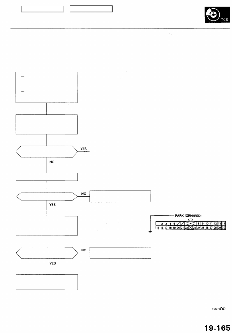
GAUGE ASSEMBLY 30P CONNECTOR

Check the gauge assembly:
Connect the gauge assembly 30P
connector terminal No. 5 to body
ground with a jumper wire.

Wire side of female terminals

Does the brake system light
come ON?

Replace the printed circuit board
in the gauge assembly.

Repair open in the wire between

the gauge assembly and parking

brake switch.

JUMPER
WIRE

Check the brake system light bulb.

When test-driving the vehicle
at 6 mph (10 km/h) or over for

more than 30 seconds, the TCS
indicator light comes ON.
With the SCS service connec-
tor connected (see page

19-159

), DTC 2 is indicated.

Check the brake system light
power source:

1. Turn the ignition switch ON (II).

2. Press the parking brake pedal.

Main Menu

Table of Contents

Troubleshooting

Parking Brake (cont'd)

From page 

19-165

Does the brake system light

go off?

Problem verification:
Test-drive the vehicle at speeds
of 6 mph (10 km/h) or more for

more than 30 seconds.

Does the TCS indicator light
come on?

The probable cause was driving
with the parking brake applied
for more than 30 seconds.

TCS CONTROL UNIT 20P CONNECTOR

Check for an open in the PARK cir-
cuit:

Measure the voltage between the

TCS control unit 20P connector
terminal No. 2 and body ground.

Wire side of female terminals

Is there battery voltage?

Repair open in the wire between
the gauge assembly and TCS con-
trol unit.

Check the front brake pad thick-
ness and brake system for leaks.
If there are no problems, refill the
master cylinder reservoir to the
correct level.

To page 

19-167

Is the level correct?

Check the brake fluid level in the
master cylinder reservoir.

Replace the TCS control unit.
(Open circuit inside the unit)

Main Menu

Table of Contents

From page 

19-166

Check the brake fluid level switch:

Disconnect the brake fluid level

switch connectors.

Does the brake system light go off?

Replace the brake fluid level
switch. (Switch stuck ON)

Check the parking brake switch
(see page 19-8).

Is the switch OK?

Replace the parking brake switch.
(Switch stuck ON)

Check for a short to body ground
in the PARK circuit:
Disconnect the TCS control unit
connector.

Does the brake system light
go off?

Replace the TCS control unit.
(Short to body ground inside the
unit)

Repair short to body ground in
the wire between the brake sys-
tem light, parking brake switch
and brake fluid level switch.

Main Menu

Table of Contents

Troubleshooting

Steering Angle Sensor

Diagnostic Trouble Code (DTC) 2-1: Steering Angle Sensor Diagnosis

The TCS control unit performs the self-diagnosis for the steering angle sensor when the speed of the four wheels exceeds

6 mph (10 km/h) on a smooth road. The TCS indicator light comes on if a yaw rate is generated, the corresponding steer-

ing angle signal is not input when the steering wheel is turned, and there is no input from the STOP (brake pedal position
switch signal) and PARK (parking brake switch signal).

With engine running, TCS indi-
cator light is ON.
The tire pressure is correct,
and tires with a correct diame-
ter are installed.
With the SCS service connec-
tor connected (see page

19-159

), DTC 2-1 is indicated.

Check for a short to body ground

in the wires between the TCS con-

trol unit and steering angle sensor:

1. Disconnect the TCS control unit

14P and 20P connectors and

steering angle sensor connec-

tor.

2. Check for continuity between

body ground and TCS control
unit 14P connector terminals
No. 9 and No. 13 individually
and between the 20P connec-

tor terminal No. 4 and No. 16

individually.

Is there continuity?

Check the STR-VCC circuit inside
the TCS control unit:

1. Connect the TCS control unit

14P and 20P connectors.

2. Turn the ignition switch ON (II).
3. Measure the voltage between

the TCS control unit 20P con-

nector terminal No. 16 and
body ground.

Is there about 5 V?

Check the STR-GND circuit inside
the TCS control unit:

Measure the voltage between the
TCS control unit 20P connector ter-
minal No. 4 and No. 16.

Is there about 5 V?

To page 

19-169

TCS CONTROL UNIT 14P CONNECTOR

Wire side of female terminals

TCS CONTROL UNIT 20P CONNECTOR

Repair short to body ground in the

wire(s) between the TCS control

unit and steering angle sensor.

Wire side of female terminals

Replace the TCS control unit.

Replace the TCS control unit.

Main Menu

Table of Contents


Content   ..  532  533  534  535   ..