Acura RL (1996-2004 year). Manual - part 532


  Index      Acura     Acura RL 1996-2004 year - service repair manual


Search            


Content   ..  530  531  532  533   ..


Acura RL (1996-2004 year). Manual - part 532


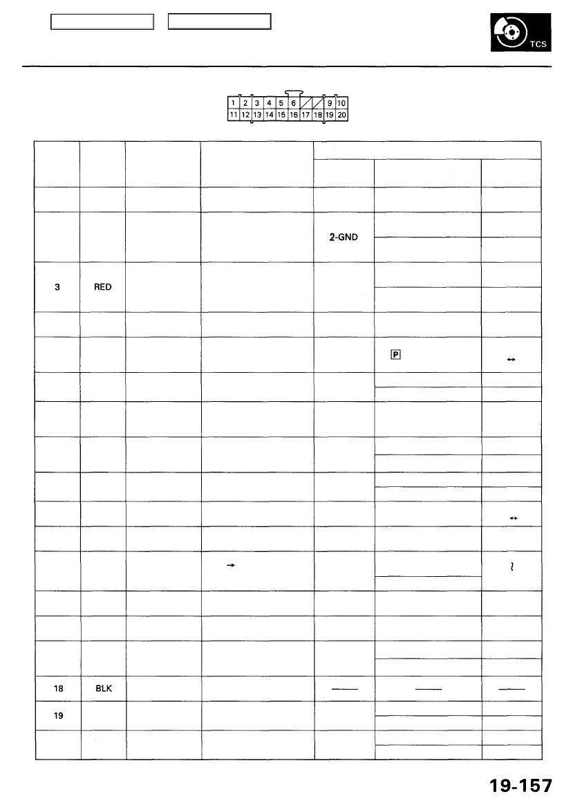
TCS CONTROL UNIT 20P CONNECTOR

Wire side of female terminals

VB: Battery Voltage

Terminal

number

1

2

4

5

6

9

10

11

12

13

14

15

16

17

20

Wire

color

BLK/YEL

GRN/RED

BLU

PNK/BLU

BLK/WHT

BLK

BRN/WHT

GRN/WHT

BLU

GRN/ORN

BLK/ORN

BRN/BLK

WHT/BLU

BLU/GRY

GRN

BRN

Terminal sign

(Terminal name)

IG1

(Ignition 1)

PARK

(Parking)

SCS

(Service check

signal)

STR-GND

(Steering ground)

AT-SHIFT

(AT shift)

FSR

(Fail-safe relay)

PMG

(Power motor

Ground)

VPM

(Voltage power

motor)

STOP

(Stop)

NEP (Engine

speed pulse)

BARO

(Barometric)

TC-FC

(Traction control

fuel cut)

LG2

(Logic ground 2)

STR-VCC (Steer-

ing power supply)

WARN2

(Warning 2)

SH-MOT

(Shield motor)

MOT +

(Motor +)

MOT-

(Motor -)

Description

Detects ignition switch
IG1 signal

Detects parking brake

switch signal

Detects service check
connector signal
(Diagnostic trouble
code indication)

Ground for the steering
angle sensor

Detects A/T shift posi-

tion signal

Drives fail-safe relay

Power ground for the

TCS control valve
actuator motor

Power source for the

TCS control valve

actuator motor

Detects brake pedal
position switch signal

Detects engine speed
signal

Detects barometric

sensor signal

TCS Fl, Fuel cut

(torque down) signal

Ground for the logic

circuit

Power source for the
steering angle sensor

Drives TCS indicator light
(The indicator light comes

on by the self-bias)

Shield for the TCS con-
trol valve actuator motor

Drives TCS control

valve actuator motor

Drives TCS control

valve actuator motor

Measurement

terminals

1-GND

3-GND

4-GND

5-GND

6-GND

9-GND

10-GND

11-GND

12-GND

13-GND

14-GND

15-GND

16-GND

17-GND

19-20

20-19

Voltage

Conditions

(Ignition Switch ON (II))

Depress the parking
brake pedal.

Release the parking
brake pedal.

SCS service connector
connected.

SCS service connector
disconnected.

Shift the transmission

to position, then

start the engine.

Start the engine.

Start the engine.

Brake pedal depressed.

Brake pedal released.

Engine idling

TCS is functioning,

(maximum fuel cut)

TCS is not functioning.

Indicator light ON

Indicator light OFF

TCS is functioning.

TCS is not functioning.

TCS is functioning.

TCS is not functioning.

Output

voltage

VB

Below 0.6 V

VB

0 V

5 V

Below 0.3V

About  4 V

(5V 0V)

VB

1.5V

Below 0.3 V

0V

VB

VB

0 V

About 6V

(12V 0V)

About 3 V

About 1.5V

About 4.5 V

(5 V, PWM)

Below 0.3V

About 5 V

About 2 V

VB

VB

0 V

VB

0 V

Main Menu

Table of Contents

Troubleshooting Precautions

1. In any of these cases, the TCS indicator light may come on or stay on even the TCS system is normal.

The coolant temperature is 32°F (0°C) or below.
The parking brake is applied for more than 30 seconds while the vehicle is being driven.
The tires are not inflated to the specified pressure.
The wheel sensor signal is interrupted during driving at speeds of 6 mph (10 km/h) or above due to, for example, a
vehicle spinning.
The MAP sensor, the coolant temperature sensor, the ICM or the atmospheric pressure sensor system of the PGM-FI
system is faulty.

2. TCS does not function when the TCS indicator light is ON.

3. When both the TCS indicator light and the MIL are ON, troubleshoot the PGM-FI system first.

4. When both the TCS indicator light and the ABS indicator light are ON, troubleshoot the ABS first.

5. The DTC 4-9 (ABS down) is memorized when the ABS control unit cannot output the wheel speed signal due to, for

example, a missing or blown ABS B2 (15 A) fuse. If you fail to erase the DTC of the TCS after troubleshooting the ABS,
the DTC remains in the TCS control unit memory. Therefore, be sure to test-drive the vehicle, and check the TCS indica-
tor light before starting to troubleshoot the TCS.

Main Menu

Table of Contents

Diagnostic Trouble Code (DTC)

Diagnostic Trouble Code (DTC) Indication

1. Connect the SCS service connector to the service check connector under the glove box.

2. Turn the ignition switch ON (II), but do not start the engine.

3. Record the blinking frequency of the TCS indicator light. The blinking frequency indicates the diagnostic trouble code

(DTC).

4. Turn the ignition switch off, and remove the SCS service connector.

NOTE: The Malfunction Indicator Lamp (MIL) will stay on after the engine is started if the SCS service connector is con-
nected.

5. Perform the DTC erasure.

SERVICE CHECK
CONNECTOR (2P)

SCS SERVICE CONNECTOR

07PAZ-0010100

DTC Indication Pattern

TCS INDICATOR LIGHT

Turn the ignition switch ON (II). The TCS indicator light comes on to check the bulb. Do not count it as DTC.
The TCS control unit can memorize up to 3 DTCs.
A new DTC is not memorized when the TCS control unit has already memorized the same DTC.
The TCS control unit indicates the DTC repeatedly at intervals of 3.3 seconds.

If you miscount the blinking frequency or if you recheck the blinking frequency, turn the ignition switch OFF, then turn
it ON (II) to cycle the TCS indicator light again.

Main Menu

Table of Contents

Diagnostic Trouble Code (DTC)

DTC Erasure

1. Press the parking brake pedal.

2. Push and hold the TCS switch, then turn the ignition switch ON (II).

3. Hold the TCS switch pushed for 4 to 6 seconds, then release the TCS switch.

4. After 3 seconds, the TCS indicator light should go off and blink 2 times, then stay on. This means that the DTC is

erased.

NOTE:

Always follow these steps exactly. If you connect the SCS service connector and/or release the parking brake pedal dur-

ing these steps, the DTC will not be erased.
If the TCS indicator light blinks repeatedly, replace the TCS control unit.

Standard Indication Pattern

Abnormal Indication Pattern

Light blinks repeatedly

Main Menu

Table of Contents


Content   ..  530  531  532  533   ..