Acura RL (1996-2004 year). Manual - part 469
Driveshafts
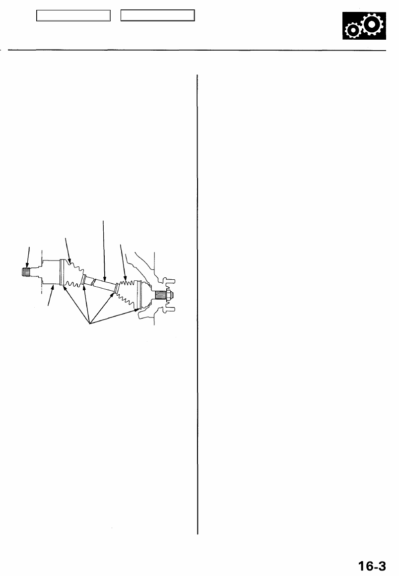
Inspection
Boot Damage
Check the boots on the driveshaft for cracks, damage,
leaking grease, and loose boot bands. If any damage is
found, replace the boot and boot bands.
Loose Splines
Turn the driveshaft by hand, and make sure the splines
and joint are not excessively loose. If damage is found,
replace the joints if necessary.
Twisting or Cracking
Make sure the driveshaft is not twisted or cracked.
Replace it if necessary.
DRIVESHAFT
INBOARD BOOT
SPLINES
OUTBOARD BOOT
INBOARD JOINT
BOOT BANDS
Main Menu
Table of Contents