Acura RL (1996-2004 year). Manual - part 300
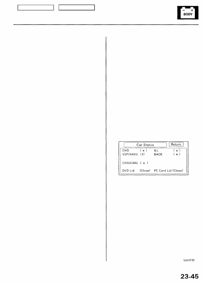
Car Status
This screen is used to confirm that navigation unit is
properly receiving input signals. Signals equal to (0) are
OFF, and signals equal to (1) are ON.If the value on the
display does not match the actual vehicle status, then
check the wire carrying the signal.
• CHG and CHG(CAN) are not used for this model.
• VSP-Vehicle Speed Pulse from PCM
(Pin 6 of C-connector)
a) OFF (0) when vehicle is not moving
b) ON (1) when vehicle is moving
The VSP comes from the PCM as a dedicated signal.
Internally, the navigation unit compares the actual VP on
the map against street data to adjust the pulse to speed
scaling factor. As this scaling factor becomes more
accurate, the "Level" gradually increases from 0 to 10
(see the Tire Calibrate diagnostic screen).
• BACK-Reverse indication from reverse relay
(Pin 5 of C-connector)
a) OFF (0) when shift lever is in any position other
than reverse
b) ON (1) when shift lever is in reverse
The Back signal is used by the navigation unit to allow
the map screen to show the VP moving backwards when
in reverse. This signal is needed because the Speed
Pulse has no direction indication.
• ILL-lllumination Indication
(Pin 5 of navigation unit A-connector)
a) OFF (0) when parking lights, or headlights are off
b) ON (1) when parking lights, or headlights are on
This signal is used by the navigation unit to determine
whether to put the navigation screen into the Day or
Night brightness mode. (Setup screen 1)
• DVD Lid-senses if DVD door is open
a) (Close) when door is closed
b) (Open) when door is open
The navigation unit has a micro switch to detect this. If
open is indicated when the door is closed, replace the
navigation unit.
• PC Card Lid-Senses if PC Card door is open
a) (Close) when door is closed
b) (Open) when door is open
The navigation unit has a micro switch to detect this. If
open is indicated when the door is slid shut, then
replace the navigation unit. This slot is for insertion of
PC Flash memory cards for gathering diagnostic infor-
mation. This is for factory use only.
Main Menu
Table of Contents