Acura RL (1996-2004 year). Manual - part 296


  Index      Acura     Acura RL 1996-2004 year - service repair manual


Search            


Content   ..  294  295  296  297   ..


Acura RL (1996-2004 year). Manual - part 296


Navigation System

Symptom Troubleshooting (cont'd)

Display unit buttons do not work

NOTE:
• Always check the connectors for poor connections or

loose terminals.

• Before troubleshooting, get the navigation system

anti-theft codes.

• After troubleshooting, enter the navigation system

anti-theft codes.

1 . Turn the ignition switch to ACC (I).

2. Go into the Diagnostic mode and use "Touch Panel"

diagnostic under Monitor Check (see page 

23-41

)

and, if necessary, "Display" diagnostic under Unit
Check (see page 

23-43

).

Do the buttons work properly?

YES—System is OK.

NO—Go to step 3.

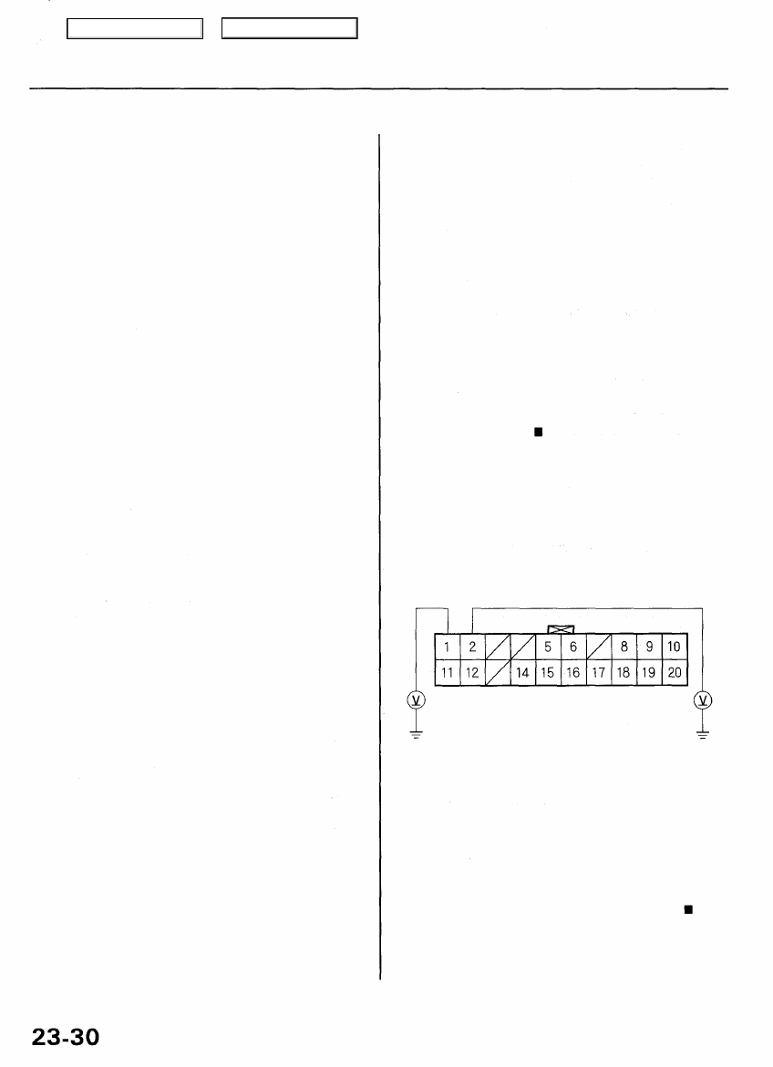
3. Measure the voltage between body ground and dis-

play unit connector B (20P) terminal No. 1 and No. 2
individually.

DISPLAY UNIT CONNECTOR B (20P)

+B
(WHT/YEL) ACC (WHT/YEL)

Wire side of female terminals

Is there battery voltage?

YES—Go to step 4.

NO—If the + B wire does not have voltage, repair the
open in the wire between the under-hood fuse/relay
box and the display unit. If the ACC wire does not
have voltage, repair the open in the wire between the
under-dash fuse/relay box and the display unit.

Main Menu

Table of Contents

- +

BODY

4. Turn the ignition switch OFF.

5. Disconnect the display unit connector B (20P).

6. Check for continuity between display unit connector

B (20P) terminal No.  1 0 and body ground.

DISPLAY UNIT CONNECTOR B (20P)

Wire side of female terminals

Is there continuity?

YES—Go to step 7.

NO—Repair the open in the wire between the display
unit and body ground (G251).

7. Disconnect the navigation unit connector A (20P).

8. Check for continuity between body ground and dis-

play unit connector B (20P) terminal No. 5 and No.  1 5
individually.

DISPLAY UNIT CONNECTOR B (20P)

DISP BUS {+)

(BLK)

Wire side of female terminals

Is there continuity?

YES—There is a short to body ground in the circuit

between the display unit and the navigation unit.
Replace the affected shielded harness.

NO—Go to step 9.

9. Check for continuity between display unit connector

B (20P) terminal No. 5 and navigation unit connector

A (20P) terminal No. 10.

DISPLAY UNIT CONNECTOR B (20P)

DISP BUS {+} (BLK)

Wire side of female terminals

Is there continuity?

YES—Go to step 10.

NO—There is an open in the circuit between the dis-

play unit and the navigation unit. Check for poor con-
nections or loose terminals at the display and naviga-

tion units. If a poor connection or loose terminal is
found, replace the affected shielded harness.

(cont'd)

Main Menu

Table of Contents

Navigation System

Symptom Troubleshooting (cont'd)

10. Check for continuity between display unit connector

B (20P) terminal No. 15 and navigation unit connec-

tor A (20P) terminal No. 20.

Wire side of female terminals

Is there continuity?

YES—Replace the display unit (see page 

23-54

).

NO—There is an open in the circuit between the dis-
play unit and the navigation unit. Check for poor con-
nections or loose terminals at the display and naviga-

tion units. If a poor connection or loose terminal is
found, replace the affected shielded harness.

Main Menu

Table of Contents

Navigation System

Symptom Troubleshooting (cont'd)

GPS icon is white

Diagnostic Test: Navigation System Link

NOTE:
• Make sure the vehicle is parked outside and away

from buildings.

• Refer to GPS information (see page 

23-46

) for real-

time satellite reception display.

Before assuming that a GPS antenna reception com-
plaint is hardware related, be aware of the following:

• The GPS signal is extremely weak (about one bil-

lionth the strength of a radio broadcast signal
received by a radio antenna)

• If the rear window has been tinted with metallic

tint, this can seriously degrade or block GPS

reception.

• Loose items on the rear shelf can block satellite

antenna reception.

• Aftermarket devices like Lo-Jack, remote starters

or other electronic devices located near the navi-
gation unit or GPS antenna can potentially inter-

fere with the operation of the navigation and On-

Star systems.

1 . Check for electronic aftermarket accessories (possibly

hidden) mounted near the GPS antenna or the navi-
gation unit.

Are there any electronic accessories?

YES—Disable the accessories and recheck,

NO—Go to step 2.

2. Go into the Diagnostic mode and use the "Navi

System Link" diagnostic (see page 

23-40

) to check

the GPS antenna.

Is "GPS Ant" icon red?

YES—Use the "Navi ECU" diagnostic under Unit
Check (see page 

23-43

) to check for a kinked, crushed,

or disconnected GPS antenna wire. If icon is still red,
replace the GPS antenna.

NO—Check that nothing is blocking the GPS antenna
located under the rear shelf and recheck. Substitute
a known-good navigation unit, and recheck.

Main Menu

Table of Contents


Content   ..  294  295  296  297   ..