Acura RL. Manual - part 442


  Index      Acura     Acura RL - service repair manual 2005-2008 year


Search            


Content   ..  440  441  442  443   ..


Acura RL. Manual - part 442


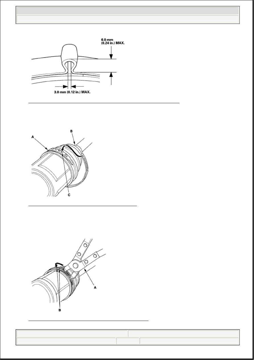
Fig. 120: Identifying Clearance Between Closed Ear Portion Of Band 
Courtesy of AMERICAN HONDA MOTOR CO., INC. 

12. Install the new low profile band (A) onto the boot (B), then hook the tab (C) of the band. 

Fig. 121: Identifying Low Profile Band Onto Boot 
Courtesy of AMERICAN HONDA MOTOR CO., INC. 

13. Close the hook portion of the band with a commercially available boot band pliers (A), then hook the 

tabs (B) of the band. 

Fig. 122: Identifying Boot Band Pliers, Hook And Tabs 
Courtesy of AMERICAN HONDA MOTOR CO., INC.


2007 Acura RL 

2005-08 DRIVELINE/AXLES Driveline/Axle - RL


me 


Friday, June 05, 2009 3:01:08 PM

Page 54 

© 2005 Mitchell Repair Information Company, LLC. 

REAR DRIVESHAFT INSTALLATION

1. Apply 1.5-2.0 g (0.05-0.07 oz.) of grease to the whole splined surface (A). After applying grease, 

remove the grease from the splined grooves at intervals of 2-3 splines and from the set ring groove (B) 
so that air can bleed from the differential. 

Fig. 123: Identifying Splined Surface And Ring Groove 
Courtesy of AMERICAN HONDA MOTOR CO., INC. 

2. Install the outboard joint (A) into the rear hub (B). 

Fig. 124: Identifying Outboard Joint, Rear Hub And Wheel Sensor 
Courtesy of AMERICAN HONDA MOTOR CO., INC. 

3. Seat a new set ring in the set ring groove of the differential.  

4. Clean the areas where the driveshaft contacts the differential thoroughly with brake cleaner, and dry 

with compressed air. Do not wash the rubber parts insolvent. Insert the inboard end (A) of the 
driveshaft into the differential (B) until the set ring (C) locks in the groove (D). 

NOTE:

Before starting installation, make sure the mating surfaces of the joint and 
the splined section are free from dirt or dust.

NOTE:

Be careful not to damage the wheel sensor (C).


2007 Acura RL 

2005-08 DRIVELINE/AXLES Driveline/Axle - RL


me 


Friday, June 05, 2009 3:01:08 PM

Page 55 

© 2005 Mitchell Repair Information Company, LLC. 

Fig. 125: Installing Inboard End Of Driveshaft Into Differential 
Courtesy of AMERICAN HONDA MOTOR CO., INC. 

5. Install the rear differential (see REAR DIFFERENTIAL INSTALLATION ).  

6. Apply a small amount of engine oil to the seating surface of the new spindle nut (A). 

Fig. 126: Identifying Spindle Nut And Wheel Nut With Torque Specifications 
Courtesy of AMERICAN HONDA MOTOR CO., INC. 

7. Install a new spindle nut, then torque the nut. After tightening, use a drift to stake the spindle nut 

shoulder (B) against the driveshaft.  

8. Clean the mating surfaces of the brake disc and the wheel, then install the rear wheels and torque the 

wheels nuts.  

9. Turn the rear wheel by hand, and make sure there is no interference between the driveshaft and 

surrounding parts.  

10. Check the rear wheel alignment, and adjust it if necessary (see WHEEL ALIGNMENT ).  

PROPELLER SHAFT INSPECTION 

UNIVERSAL JOINT AND BOOTS 

1. Shift the transmission to the N position.  

2. Raise the vehicle on a lift (see LIFT AND SUPPORT POINTS ).  

3. Check the center support bearing (A) for excessive play or rattle. If the center support has excessive 

play or rattle, replace the propeller shaft assembly. 


2007 Acura RL 

2005-08 DRIVELINE/AXLES Driveline/Axle - RL


me 


Friday, June 05, 2009 3:01:08 PM

Page 56 

© 2005 Mitchell Repair Information Company, LLC. 

Fig. 127: Identifying Center Support Bearing 
Courtesy of AMERICAN HONDA MOTOR CO., INC. 

4. Check the universal joint boots for damage and deterioration. If the boots are damaged or deteriorated, 

replace the propeller shaft assembly.  

5. Check the universal joints for excessive play or rattle. If the universal joints have excessive play or 

rattle, replace the propeller shaft assembly.  

PROPELLER SHAFT 

1. Inspect the surface of No. 1 and No. 2 propeller shaft damage. If it is damaged, replace the propeller 

shaft assembly.  

2. Inspect the difference (A) of No. 1 propeller shaft, especially if the vehicle has been in a collision. If 

there is difference in alignment, replace the propeller shaft assembly. 

Fig. 128: Inspecting Difference Of No. 1 Propeller Shaft 
Courtesy of AMERICAN HONDA MOTOR CO., INC. 

PROPELLER SHAFT RUNOUT 

1. Install a dial indicator with its needle on the center of No. 1 propeller shaft or No. 2 propeller shaft.  

2. Turn the other propeller shaft slowly and check the runout. Repeat this procedure for the other 

propeller shaft. 


2007 Acura RL 

2005-08 DRIVELINE/AXLES Driveline/Axle - RL


me 


Friday, June 05, 2009 3:01:08 PM

Page 57 

© 2005 Mitchell Repair Information Company, LLC. 


Content   ..  440  441  442  443   ..