содержание .. 166 167 168 169 ..
Kia Sedona (2008 year). Manual - part 168
REPAIR" procedure.
2. Check right outside mirror sensor
1. Connect scan tool to Data Link Connector (DLC).
2. Ignition "ON" & engine "OFF"
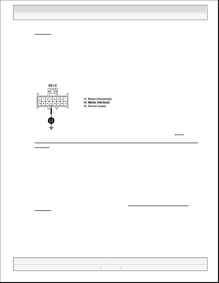
3. Measure voltage value between terminal "13" of outside mirror and chassis ground. While
operating outside mirror switch.
Specification: bottom end --> approx. 0.88V, upper end --> approx. 3.86V
Fig. 111: Measuring Voltage Value Between Terminal 13 Of Outside Mirror And Chassis
Ground
Courtesy of KIA MOTORS AMERICA, INC.
4. Is the measured voltage within specifications?
YES
Go to step 3.
NO
Substitute with a known-good right outside mirror and check for proper operation. If the problem is
corrected, replace right outside mirror and then go to "VERIFICATION OF VEHICLE
REPAIR" procedure.
3. Check ADM
1. Connect scan tool to Data Link Connector (DLC).
2. Ignition "ON" & engine "OFF"
3. Measure voltage value between terminal "10, 11" of outside mirror and chassis ground. While
operating outside mirror switch.
Specification: 9-16V
2008 Kia Sedona EX
2008 ACCESSORIES & BODY, CAB BCM (Body Control Module) - Sedona
Microsoft
Monday, May 24, 2010 4:19:18 PM
Page 141
© 2006 Mitchell Repair Information Company, LLC.