Intel 64 and IA-32 Architectures. Software Developer’s Manual (Collection, 2023) - page 148

GENERAL OPTIMIZATION GUIDELINES
The following rules apply to branch elimination:
Assembly/Compiler Coding Rule 1. (MH impact, M generality) Arrange code to make basic blocks
contiguous and eliminate unnecessary branches.
Assembly/Compiler Coding Rule 2. (M impact, ML generality) Use the SETCC and CMOV
instructions to eliminate unpredictable conditional branches where possible. Do not do this for
predictable branches. Do not use these instructions to eliminate all unpredictable conditional branches
(because using these instructions will incur execution overhead due to the requirement for executing
both paths of a conditional branch). In addition, converting a conditional branch to SETCC or CMOV
trades off control flow dependence for data dependence and restricts the capability of the out-of-order
engine. When tuning, note that all Intel 64 and IA-32 processors usually have very high branch
prediction rates. Consistently mispredicted branches are generally rare. Use these instructions only if
the increase in computation time is less than the expected cost of a mispredicted branch.
Consider a line of C code that has a condition dependent upon one of the constants:
X = (A < B) CONST1 : CONST2;
This code conditionally compares two values, A and B. If the condition is true, X is set to CONST1; other-
wise it is set to CONST2. An assembly code sequence equivalent to the above C code can contain
branches that are not predictable if there are no correlation in the two values.
Example 3-1 shows the assembly code with unpredictable branches. The unpredictable branches can be
removed with the use of the SETCC instruction. Example 3-2 shows optimized code that has no
branches.
Example 3-1. Assembly Code with an Unpredictable Branch
cmp a, b
; Condition
jbe L30
; Conditional branch
mov ebx const1
; ebx holds X
jmp L31
; Unconditional branch
L30:
mov ebx, const2
L31:
Example 3-2. Code Optimization to Eliminate Branches
xor ebx, ebx
; Clear ebx (X in the C code)
cmp A, B
setge bl
; When ebx = 0 or 1
; OR the complement condition
sub ebx, 1
; ebx=11...11 or 00...00
and ebx, CONST3; CONST3 = CONST1-CONST2
add ebx, CONST2; ebx=CONST1 or CONST2
The optimized code in Example 3-2 sets EBX to zero, then compares A and B. If A is greater than or equal
to B, EBX is set to one. Then EBX is decreased and AND’d with the difference of the constant values. This
sets EBX to either zero or the difference of the values. By adding CONST2 back to EBX, the correct value
is written to EBX. When CONST2 is equal to zero, the last instruction can be deleted.
Another way to remove branches is to use the CMOV and FCMOV instructions. Example 3-3 shows how to
change a TEST and branch instruction sequence using CMOV to eliminate a branch. If the TEST sets the
equal flag, the value in EBX will be moved to EAX. This branch is data-dependent, and is representative
of an unpredictable branch.
Ref#: 248966-048
3-5

GENERAL OPTIMIZATION GUIDELINES
Example 3-3. Eliminating Branch with CMOV Instruction
test ecx, ecx
jne 1H
mov eax, ebx
1H:
; To optimize code, combine jne and mov into one cmovcc instruction that checks the equal flag
test ecx, ecx
; Test the flags
cmoveq eax, ebx
; If the equal flag is set, move
; ebx to eax- the 1H: tag no longer needed
An extension to this concept can be seen in the AVX-512 masked operations, as well as in some instruc-
tions such as VPCMP which can be used to eliminate data dependent branches; see Section 18.4.
3.4.1.2
Static Prediction
Branches that do not have a history in the BTB (see Section 3.4.1) are predicted using a static prediction
algorithm:
• Predict forward conditional branches to be NOT taken.
• Predict backward conditional branches to be taken.
• Predict indirect branches to be NOT taken.
The following rule applies to static prediction:
Assembly/Compiler Coding Rule 3. (M impact, H generality) Arrange code to be consistent with
the static branch prediction algorithm: make the fall-through code following a conditional branch be the
likely target for a branch with a forward target, and make the fall-through code following a conditional
branch be the unlikely target for a branch with a backward target.
Example 3-4 illustrates the static branch prediction algorithm. The body of an IF-THEN conditional is
predicted.
Example 3-4. Static Branch Prediction Algorithm
//Forward condition branches not taken (fall through)
IF<condition> {
}
IF<condition> {...
}
//Backward conditional branches are taken
LOOP {...
<condition>
//Unconditional branches taken
JMP
------
Example 3-5 and Example 3-6 provide basic rules for a static prediction algorithm. In Example 3-5, the
backward branch (JC BEGIN) is not in the BTB the first time through; therefore, the BTB does not issue a
Ref#: 248966-048
3-6

GENERAL OPTIMIZATION GUIDELINES
prediction. The static predictor, however, will predict the branch to be taken, so a misprediction will not
occur.
Example 3-5. Static Taken Prediction
Begin: mov
eax, mem32
and
eax, ebx
imul
eax, edx
shld
eax, 7
jc
Begin
The first branch instruction (JC BEGIN) in Example 3-6 is a conditional forward branch. It is not in the
BTB the first time through, but the static predictor will predict the branch to fall through. The static
prediction algorithm correctly predicts that the CALL CONVERT instruction will be taken, even before the
branch has any branch history in the BTB.
Example 3-6. Static Not-Taken Prediction
mov
eax, mem32
and
eax, ebx
imul
eax, edx
shld
eax, 7
jc
Begin
mov
eax, 0
Begin: call
Convert
The Intel Core microarchitecture does not use the static prediction heuristic. However, to maintain
consistency across Intel 64 and IA-32 processors, software should maintain the static prediction heuristic
as the default.
3.4.1.3
Inlining, Calls, and Returns
The return address stack mechanism augments the static and dynamic predictors to optimize specifically
for calls and returns. It holds 16 entries, which is large enough to cover the call depth of most programs.
If there is a chain of more than 16 nested calls and more than 16 returns in rapid succession, perfor-
mance may degrade.
To enable the use of the return stack mechanism, calls and returns must be matched in pairs. If this is
done, the likelihood of exceeding the stack depth in a manner that will impact performance is very low.
The following rules apply to inlining, calls, and returns:
Assembly/Compiler Coding Rule 4. (MH impact, MH generality) Near calls must be matched with
near returns, and far calls must be matched with far returns. Pushing the return address on the stack
and jumping to the routine to be called is not recommended since it creates a mismatch in calls and
returns.
Calls and returns are expensive; use inlining for the following reasons:
• Parameter passing overhead can be eliminated.
• In a compiler, inlining a function exposes more opportunity for optimization.
• If the inlined routine contains branches, the additional context of the caller may improve branch
prediction within the routine.
• A mispredicted branch can lead to performance penalties inside a small function that are larger than
those that would occur if that function is inlined.
Ref#: 248966-048
3-7
GENERAL OPTIMIZATION GUIDELINES
Assembly/Compiler Coding Rule 5. (MH impact, MH generality) Selectively inline a function if
doing so decreases code size or if the function is small and the call site is frequently executed.
Assembly/Compiler Coding Rule 6. (ML impact, ML generality) If there are more than 16 nested
calls and returns in rapid succession; consider transforming the program with inline to reduce the call
depth.
Assembly/Compiler Coding Rule 7. (ML impact, ML generality) Favor inlining small functions that
contain branches with poor prediction rates. If a branch misprediction results in a RETURN being
prematurely predicted as taken, a performance penalty may be incurred.
Assembly/Compiler Coding Rule 8. (L impact, L generality) If the last statement in a function is
a call to another function, consider converting the call to a jump. This will save the call/return overhead
as well as an entry in the return stack buffer.
Assembly/Compiler Coding Rule 9. (M impact, L generality) Do not put more than four branches
in a 16-byte chunk.
Assembly/Compiler Coding Rule 10. (M impact, L generality) Do not put more than two end loop
branches in a 16-byte chunk.
3.4.1.4
Code Alignment
Careful arrangement of code can enhance cache and memory locality. Likely sequences of basic blocks
should be laid out contiguously in memory. This may involve removing unlikely code, such as code to
handle error conditions, from the sequence. See Section 3.7 on optimizing the instruction prefetcher.
Assembly/Compiler Coding Rule 11. (M impact, H generality) When executing code from the
Decoded ICache, direct branches that are mostly taken should have all their instruction bytes in a 64B
cache line and nearer the end of that cache line. Their targets should be at or near the beginning of a
64B cache line.
When executing code from the legacy decode pipeline, direct branches that are mostly taken should have
all their instruction bytes in a 16B aligned chunk of memory and nearer the end of that 16B aligned
chunk. Their targets should be at or near the beginning of a 16B aligned chunk of memory.
Assembly/Compiler Coding Rule 12. (M impact, H generality) If the body of a conditional is not
likely to be executed, it should be placed in another part of the program. If it is highly unlikely to be
executed and code locality is an issue, it should be placed on a different code page.
3.4.1.5
Branch Type Selection
The default predicted target for indirect branches and calls is the fall-through path. Fall-through predic-
tion is overridden if and when a hardware prediction is available for that branch. The predicted branch
target from branch prediction hardware for an indirect branch is the previously executed branch target.
The default prediction to the fall-through path is only a significant issue if no branch prediction is avail-
able, due to poor code locality or pathological branch conflict problems. For indirect calls, predicting the
fall-through path is usually not an issue, since execution will likely return to the instruction after the
associated return.
Placing data immediately following an indirect branch can cause a performance problem. If the data
consists of all zeros, it looks like a long stream of ADDs to memory destinations and this can cause
resource conflicts and slow down branch recovery. Also, data immediately following indirect branches
may appear as branches to the branch predication hardware, which can branch off to execute other data
pages. This can lead to subsequent self-modifying code problems.
Assembly/Compiler Coding Rule 13. (M impact, L generality) When indirect branches are
present, try to put the most likely target of an indirect branch immediately following the indirect
branch. Alternatively, if indirect branches are common but they cannot be predicted by branch
prediction hardware, then follow the indirect branch with a UD2 instruction, which will stop the
processor from decoding down the fall-through path.
Indirect branches resulting from code constructs (such as switch statements, computed GOTOs or calls
through pointers) can jump to an arbitrary number of locations. If the code sequence is such that the
target destination of a branch goes to the same address most of the time, then the BTB will predict accu-
Ref#: 248966-048
3-8

GENERAL OPTIMIZATION GUIDELINES
rately most of the time. Since only one taken (non-fall-through) target can be stored in the BTB, indirect
branches with multiple taken targets may have lower prediction rates.
The effective number of targets stored may be increased by introducing additional conditional branches.
Adding a conditional branch to a target is fruitful if:
• The branch direction is correlated with the branch history leading up to that branch; that is, not just
the last target, but how it got to this branch.
• The source/target pair is common enough to warrant using the extra branch prediction capacity. This
may increase the number of overall branch mispredictions, while improving the misprediction of
indirect branches. The profitability is lower if the number of mispredicting branches is very large.
User/Source Coding Rule 1. (M impact, L generality) If an indirect branch has two or more
common taken targets and at least one of those targets is correlated with branch history leading up to
the branch, then convert the indirect branch to a tree where one or more indirect branches are
preceded by conditional branches to those targets. Apply this “peeling” procedure to the common
target of an indirect branch that correlates to branch history.
The purpose of this rule is to reduce the total number of mispredictions by enhancing the predictability of
branches (even at the expense of adding more branches). The added branches must be predictable for
this to be worthwhile. One reason for such predictability is a strong correlation with preceding branch
history. That is, the directions taken on preceding branches are a good indicator of the direction of the
branch under consideration.
Example 3-7 shows a simple example of the correlation between a target of a preceding conditional
branch and a target of an indirect branch.
Example 3-7. Indirect Branch With Two Favored Targets
function ()
{
int n = rand();
// random integer 0 to RAND_MAX
if ( ! (n & 0x01) ) {
// n will be 0 half the times
n = 0;
// updates branch history to predict taken
}
// indirect branches with multiple taken targets
// may have lower prediction rates
switch (n) {
case 0: handle_0(); break;
// common target, correlated with
// branch history that is forward taken
case 1: handle_1(); break;
// uncommon
case 3: handle_3(); break;
// uncommon
default: handle_other();
// common target
}
}
Correlation can be difficult to determine analytically, for a compiler and for an assembly language
programmer. It may be fruitful to evaluate performance with and without peeling to get the best perfor-
mance from a coding effort.
An example of peeling out the most favored target of an indirect branch with correlated branch history is
shown in Example 3-8.
Ref#: 248966-048
3-9

GENERAL OPTIMIZATION GUIDELINES
Example 3-8. A Peeling Technique to Reduce Indirect Branch Misprediction
function ()
{
int n = rand();
// Random integer 0 to RAND_MAX
if( ! (n & 0x01) ) THEN
n = 0;
// n will be 0 half the times
if (!n) THEN
handle_0();
// Peel out the most common target
// with correlated branch history
{
switch (n) {
case 1: handle_1(); break;
// Uncommon
case 3: handle_3(); break;
// Uncommon
default: handle_other();
// Make the favored target in
// the fall-through path
}
}
}
3.4.1.6
Loop Unrolling
Benefits of unrolling loops are:
• Unrolling amortizes the branch overhead, since it eliminates branches and some of the code to
manage induction variables.
• Unrolling allows one to aggressively schedule (or pipeline) the loop to hide latencies. This is useful if
you have enough free registers to keep variables live as you stretch out the dependence chain to
expose the critical path.
• Unrolling exposes the code to various other optimizations, such as removal of redundant loads,
common subexpression elimination, and so on.
The potential costs of unrolling loops are:
• Unrolling loops whose bodies contain branches increases demand on BTB capacity. If the number of
iterations of the unrolled loop is 16 or fewer, the branch predictor should be able to correctly predict
branches in the loop body that alternate direction.
Ref#: 248966-048
3-10

GENERAL OPTIMIZATION GUIDELINES
Assembly/Compiler Coding Rule 14. (H impact, M generality) Unroll small loops until the
overhead of the branch and induction variable accounts (generally) for less than 10% of the execution
time of the loop.
Assembly/Compiler Coding Rule 15. (M impact, M generality) Unroll loops that are frequently
executed and have a predictable number of iterations to reduce the number of iterations to 16 or fewer.
Do this unless it increases code size so that the working set no longer fits in the instruction cache. If the
loop body contains more than one conditional branch, then unroll so that the number of iterations is
16/(# conditional branches).
Example 3-9 shows how unrolling enables other optimizations.
Example 3-9. Loop Unrolling
Before unrolling:
do i = 1, 100
if ( i mod 2 == 0 ) then a( i ) = x
else a( i ) = y
enddo
After unrolling
do i = 1, 100, 2
a( i ) = y
a( i+1 ) = x
enddo
In this example, the loop that executes 100 times assigns X to every even-numbered element and Y to
every odd-numbered element. By unrolling the loop you can make assignments more efficiently,
removing one branch in the loop body.
3.4.2
Fetch and Decode Optimization
Intel Core microarchitecture provides several mechanisms to increase front end throughput. Techniques
to take advantage of some of these features are discussed below.
3.4.2.1
Optimizing for Microfusion
An Instruction that operates on a register and a memory operand decodes into more micro-ops than its
corresponding register-register version. Replacing the equivalent work of the former instruction using
the register-register version usually require a sequence of two instructions. The latter sequence is likely
to result in reduced fetch bandwidth.
Assembly/Compiler Coding Rule 16. (ML impact, M generality) For improving fetch/decode
throughput, Give preference to memory flavor of an instruction over the register-only flavor of the
same instruction, if such instruction can benefit from micro-fusion.
The following examples are some of the types of micro-fusions that can be handled by all decoders:
• All stores to memory, including store immediate. Stores execute internally as two separate
micro-ops: store-address and store-data.
• All “read-modify” (load+op) instructions between register and memory, for example:
ADDPS XMM9, OWORD PTR [RSP+40]
FADD DOUBLE PTR [RDI+RSI*8]
XOR RAX, QWORD PTR [RBP+32]
• All instructions of the form “load and jump,” for example:
JMP
[RDI+200]
RET
• CMP and TEST with immediate operand and memory.
An Intel 64 instruction with RIP relative addressing is not micro-fused in the following cases:
Ref#: 248966-048
3-11
GENERAL OPTIMIZATION GUIDELINES
• When an additional immediate is needed, for example:
CMP
[RIP+400], 27
MOV
[RIP+3000], 142
• When an RIP is needed for control flow purposes, for example:
JMP
[RIP+5000000]
In these cases, Intel Core microarchitecture and Sandy Bridge microarchitecture provide a 2 micro-op
flow from decoder 0, resulting in a slight loss of decode bandwidth since 2 micro-op flow must be steered
to decoder 0 from the decoder with which it was aligned.
RIP addressing may be common in accessing global data. Since it will not benefit from micro-fusion,
compiler may consider accessing global data with other means of memory addressing.
3.4.2.2
Optimizing for Macrofusion
Macrofusion merges two instructions to a single micro-op. Intel Core microarchitecture performs this
hardware optimization under limited circumstances.
The first instruction of the macro-fused pair must be a CMP or TEST instruction. This instruction can be
REG-REG, REG-IMM, or a micro-fused REG-MEM comparison. The second instruction (adjacent in the
instruction stream) should be a conditional branch.
Since these pairs are common ingredient in basic iterative programming sequences, macrofusion
improves performance even on un-recompiled binaries. All of the decoders can decode one macro-fused
pair per cycle, with up to three other instructions, resulting in a peak decode bandwidth of 5 instructions
per cycle.
Each macro-fused instruction executes with a single dispatch. This process reduces latency, which in this
case shows up as a cycle removed from branch mispredict penalty. Software also gain all other fusion
benefits: increased rename and retire bandwidth, more storage for instructions in-flight, and power
savings from representing more work in fewer bits.
The following list details when you can use macrofusion:
• CMP or TEST can be fused when comparing:
REG-REG. For example: CMP EAX,ECX; JZ label
REG-IMM. For example: CMP EAX,0x80; JZ label
REG-MEM. For example: CMP EAX,[ECX]; JZ label
MEM-REG. For example: CMP [EAX],ECX; JZ label
• TEST can fused with all conditional jumps.
• CMP can be fused with only the following conditional jumps in Intel Core microarchitecture. These
conditional jumps check carry flag (CF) or zero flag (ZF). jump. The list of macrofusion-capable
conditional jumps are:
JA or JNBE
JAE or JNB or JNC
JE or JZ
JNA or JBE
JNAE or JC or JB
JNE or JNZ
CMP and TEST can not be fused when comparing MEM-IMM (e.g. CMP [EAX],0x80; JZ label). Macrofusion
is not supported in 64-bit mode for Intel Core microarchitecture.
• Nehalem microarchitecture supports the following enhancements in macrofusion:
— CMP can be fused with the following conditional jumps (that was not supported in Intel Core
microarchitecture):
• JL or JNGE
• JGE or JNL
Ref#: 248966-048
3-12

GENERAL OPTIMIZATION GUIDELINES
• JLE or JNG
• JG or JNLE
— Macrofusion is supported in 64-bit mode.
• Enhanced macrofusion support in Sandy Bridge microarchitecture is summarized in Table 3-1 with
additional information in Example 3-14:
Table 3-1. Macro-Fusible Instructions in Sandy Bridge Microarchitecture
Instructions
TEST
AND
CMP
ADD
SUB
INC
DEC
JO/JNO
Y
Y
N
N
N
N
N
JC/JB/JAE/JNB
Y
Y
Y
Y
Y
N
N
JE/JZ/JNE/JNZ
Y
Y
Y
Y
Y
Y
Y
JNA/JBE/JA/JNBE
Y
Y
Y
Y
Y
N
N
JS/JNS/JP/JPE/JNP/JPO
Y
Y
N
N
N
N
N
JL/JNGE/JGE/JNL/JLE/JNG/JG/JNLE
Y
Y
Y
Y
Y
Y
Y
• Enhanced macrofusion support in Haswell microarchitecture is summarized in Table 3-2. Macrofusion
is supported CMP/TEST/OP with reg-imm, reg-mem, and reg-reg addressing but not mem-imm
addressing.
Table 3-2. Macro-Fusible Instructions in Haswell Microarchitecture
Opcode
JCC
ADD / SUB / CMP
INC / DEC
TEST / AND
70
0F 80
Jo
N
N
Y
71
0F 81
Jno
N
N
Y
72
0F 82
Jc / Jb
Y
N
Y
73
0F 83
Jae / Jnb
Y
N
Y
74
0F 84
Je / Jz
Y
Y
Y
75
0F 85
Jne / Jnz
Y
Y
Y
76
0F 86
Jna / Jbe
Y
N
Y
77
0F 87
Ja / Jnbe
Y
N
Y
78
0F 88
Js
N
N
Y
79
0F 89
Jns
N
N
Y
7A
0F 8A
Jp / Jpe
N
N
Y
7B
0F 8B
Jnp / Jpo
N
N
Y
7C
0F 8C
Jl / Jnge
Y
Y
Y
7D
0F 8D
Jge / Jnl
Y
Y
Y
7E
0F 8E
Jle / Jng
Y
Y
Y
7F
0F 8F
Jg / Jnle
Y
Y
Y
Ref#: 248966-048
3-13

GENERAL OPTIMIZATION GUIDELINES
Assembly/Compiler Coding Rule 17. (M impact, ML generality) Employ macrofusion where
possible using instruction pairs that support macrofusion. Prefer TEST over CMP if possible. Use
unsigned variables and unsigned jumps when possible. Try to logically verify that a variable is
non-negative at the time of comparison. Avoid CMP or TEST of MEM-IMM flavor when possible.
However, do not add other instructions to avoid using the MEM-IMM flavor.
Example 3-10. Macrofusion, Unsigned Iteration Count
Without Macrofusion
With Macrofusion
C code
for (int1 i = 0; i < 1000; i++)
for ( unsigned int2 i = 0; i < 1000; i++)
a++;
a++;
Disassembly
for (int i = 0; i < 1000; i++)
for ( unsigned int i = 0; i < 1000; i++)
mov dword ptr [ i ], 0
xor
eax, eax
jmp
First
mov
dword ptr [ i ], eax
Loop:
jmp
First
mov eax, dword ptr [ i ]
Loop:
add
eax, 1
mov
eax, dword ptr [ i ]
mov
dword ptr [ i ], eax
add
eax, 1
mov
dword ptr [ i ], eax
First:
First:
cmp dword ptr [ i ], 3E8H3
cmp eax, 3E8H 4
jge
End
jae
End
a++;
a++;
mov eax, dword ptr [ a ]
mov eax, dword ptr [ a ]
addqq eax,1
add
eax, 1
mov dword ptr [ a ], eax
mov
dword ptr [ a ], eax
jmp
Loop
jmp
Loop
End:
End:
NOTES:
1. Signed iteration count inhibits macrofusion.
2. Unsigned iteration count is compatible with macrofusion.
3. CMP MEM-IMM, JGE inhibit macrofusion.
4. CMP REG-IMM, JAE permits macrofusion.
Example 3-11. Macrofusion, If Statement
Without Macrofusion
With Macrofusion
C code
int1 a = 7;
unsigned int2 a = 7;
if ( a < 77 )
if ( a < 77 )
a++;
a++;
else
else
a--;
a--;
Disassembly
int a = 7;
unsigned int a = 7;
mov dword ptr [ a ], 7
mov dword ptr [ a ], 7
if (a < 77)
if ( a < 77 )
cmp dword ptr [ a ], 4DH 3
mov eax, dword ptr [ a ]
jge
Dec
cmp eax, 4DH
jae
Dec
Ref#: 248966-048
3-14

GENERAL OPTIMIZATION GUIDELINES
Example 3-11. Macrofusion, If Statement (Contd.)
Without Macrofusion
With Macrofusion
a++;
a++;
mov eax, dword ptr [ a ]
add
eax,1
add
eax, 1
mov
dword ptr [ a ], eax
mov
dword ptr [a], eax
else
else
jmp
End
jmp
End
a--;
a--;
Dec:
Dec:
sub
eax, 1
mov eax, dword ptr [ a ]
mov
dword ptr [ a ], eax
sub
eax, 1
End::
mov
dword ptr [ a ], eax
End::
NOTES:
1. Signed iteration count inhibits macrofusion.
2. Unsigned iteration count is compatible with macrofusion.
3. CMP MEM-IMM, JGE inhibit macrofusion.
Assembly/Compiler Coding Rule 18. (M impact, ML generality) Software can enable macro
fusion when it can be logically determined that a variable is non-negative at the time of comparison;
use TEST appropriately to enable macrofusion when comparing a variable with 0.
Example 3-12. Macrofusion, Signed Variable
Without Macrofusion
With Macrofusion
test
ecx, ecx
test
ecx, ecx
jle
OutSideTheIF
jle
OutSideTheIF
cmp
ecx, 64H
cmp
ecx, 64H
jge
OutSideTheIF
jae
OutSideTheIF
<IF BLOCK CODE>
<IF BLOCK CODE>
OutSideTheIF:
OutSideTheIF:
For either signed or unsigned variable ‘a’; “CMP a,0” and “TEST a,a” produce the same result as far as the
flags are concerned. Since TEST can be macro-fused more often, software can use “TEST a,a” to replace
“CMP a,0” for the purpose of enabling macrofusion.
Example 3-13. Macrofusion, Signed Comparison
C Code
Without Macrofusion
With Macrofusion
if (a == 0)
cmp a, 0
test a, a
jne lbl
jne lbl
lbl:
lbl:
if ( a >= 0)
cmp a, 0
test a, a
jl lbl;
jl lbl
lbl:
lbl:
Sandy Bridge microarchitecture enables more arithmetic and logic instructions to macro-fuse with condi-
tional branches. In loops where the ALU ports are already congested, performing one of these
macrofusions can relieve the pressure, as the macro-fused instruction consumes only port 5, instead of
an ALU port plus port 5.
In Example 3-14, the “add/cmp/jnz” loop contains two ALU instructions that can be dispatched via either
port 0, 1, 5. So there is higher probability of port 5 might bind to either ALU instruction causing JNZ to
Ref#: 248966-048
3-15

GENERAL OPTIMIZATION GUIDELINES
wait a cycle. The “sub/jnz” loop, the likelihood of ADD/SUB/JNZ can be dispatched in the same cycle is
increased because only SUB is free to bind with either port 0, 1, 5.
Example 3-14. Additional Macrofusion Benefit in Sandy Bridge Microarchitecture
Add + cmp + jnz alternative
Loop control with sub + jnz
lea
rdx, buff
lea
rdx, buff - 4
xor
rcx, rcx
xor
rcx, LEN
xor
eax, eax
xor
eax, eax
loop:
loop:
add
eax, [rdx + 4 * rcx]
add
eax, [rdx + 4 * rcx]
add
rcx, 1
sub
rcx, 1
cmp
rcx, LEN
jnz
loop
jnz
loop
3.4.2.3
Length-Changing Prefixes (LCP)
The length of an instruction can be up to 15 bytes in length. Some prefixes can dynamically change the
length of an instruction that the decoder must recognize. Typically, the pre-decode unit will estimate the
length of an instruction in the byte stream assuming the absence of LCP. When the predecoder encoun-
ters an LCP in the fetch line, it must use a slower length decoding algorithm. With the slower length
decoding algorithm, the predecoder decodes the fetch in 6 cycles, instead of the usual 1 cycle. Normal
queuing throughout of the machine pipeline generally cannot hide LCP penalties.
The prefixes that can dynamically change the length of a instruction include:
• Operand size prefix (0x66).
• Address size prefix (0x67).
The instruction MOV DX, 01234h is subject to LCP stalls in processors based on Intel Core microarchitec-
ture, and in Intel Core Duo and Intel Core Solo processors. Instructions that contain imm16 as part of
their fixed encoding but do not require LCP to change the immediate size are not subject to LCP stalls.
The REX prefix (4xh) in 64-bit mode can change the size of two classes of instruction, but does not cause
an LCP penalty.
If the LCP stall happens in a tight loop, it can cause significant performance degradation. When decoding
is not a bottleneck, as in floating-point heavy code, isolated LCP stalls usually do not cause performance
degradation.
Assembly/Compiler Coding Rule 19. (MH impact, MH generality) Favor generating code using
imm8 or imm32 values instead of imm16 values.
If imm16 is needed, load equivalent imm32 into a register and use the word value in the register instead.
Double LCP Stalls
Instructions that are subject to LCP stalls and cross a 16-byte fetch line boundary can cause the LCP stall
to trigger twice. The following alignment situations can cause LCP stalls to trigger twice:
• An instruction is encoded with a MODR/M and SIB byte, and the fetch line boundary crossing is
between the MODR/M and the SIB bytes.
• An instruction starts at offset 13 of a fetch line references a memory location using register and
immediate byte offset addressing mode.
The first stall is for the 1st fetch line, and the 2nd stall is for the 2nd fetch line. A double LCP stall causes
a decode penalty of 11 cycles.
Ref#: 248966-048
3-16

GENERAL OPTIMIZATION GUIDELINES
The following examples cause LCP stall once, regardless of their fetch-line location of the first byte of the
instruction:
ADD DX, 01234H
ADD word ptr [EDX], 01234H
ADD word ptr 012345678H[EDX], 01234H
ADD word ptr [012345678H], 01234H
The following instructions cause a double LCP stall when starting at offset 13 of a fetch line:
ADD word ptr [EDX+ESI], 01234H
ADD word ptr 012H[EDX], 01234H
ADD word ptr 012345678H[EDX+ESI], 01234H
To avoid double LCP stalls, do not use instructions subject to LCP stalls that use SIB byte encoding or
addressing mode with byte displacement.
False LCP Stalls
False LCP stalls have the same characteristics as LCP stalls, but occur on instructions that do not have
any imm16 value.
False LCP stalls occur when (a) instructions with LCP that are encoded using the F7 opcodes, and (b) are
located at offset 14 of a fetch line. These instructions are: not, neg, div, idiv, mul, and imul. False LCP
experiences delay because the instruction length decoder can not determine the length of the instruction
before the next fetch line, which holds the exact opcode of the instruction in its MODR/M byte.
The following techniques can help avoid false LCP stalls:
• Upcast all short operations from the F7 group of instructions to long, using the full 32 bit version.
• Ensure that the F7 opcode never starts at offset 14 of a fetch line.
Assembly/Compiler Coding Rule 20. (M impact, ML generality) Ensure instructions using 0xF7
opcode byte does not start at offset 14 of a fetch line; and avoid using these instruction to operate on
16-bit data, upcast short data to 32 bits.
Example 3-15. Avoiding False LCP Delays with 0xF7 Group Instructions
A Sequence Causing Delay in the Decoder
Alternate Sequence to Avoid Delay
neg word ptr a
movsx eax, word ptr a
neg
eax
mov
word ptr a, AX
3.4.2.4
Optimizing the Loop Stream Detector (LSD)
The LSD detects loops that have many iterations and fit into the µop-queue. The µop-queue streams the
loop until a branch miss-prediction inevitably ends it.
LSD improves fetch bandwidth. In single thread mode, it saves power by allowing the front-end to sleep.
In multi-thread mode, front-resource can better serve the other thread.
Loops qualify for LSD replay if all the following conditions are met:
• Loop body size up to 60 µops, with up to 15 taken branches, and up to 15 64-byte fetch lines.
• No CALL or RET.
• No mismatched stack operations (e.g., more PUSH than POP).
• More than ~20 iterations.
Many calculation-intensive loops, searches, and software string moves match these characteristics.
These loops exceed the BPU prediction capacity and always terminate in a branch misprediction.
Ref#: 248966-048
3-17
GENERAL OPTIMIZATION GUIDELINES
Assembly/Compiler Coding Rule 21.
(MH impact, MH generality) Break up a loop body with a
long sequence of instructions into loops of shorter instruction blocks of no more than the size of the
LSD.
Allocation bandwidth in Ice Lake Client microarchitecture increased from 4 µops per cycle to 5 µops per
cycle.
Assume a loop that qualifies for LSD has 23 µops in the loop body. The hardware unrolls the loop such
that it still fits into the µop-queue, in this case twice. The loop in the µop-queue thus takes 46 µops.
The loop is sent to allocation 5 µops per cycle. After 45 out of the 46 µops are sent, in the next cycle only
a single µop is sent, which means that in that cycle, 4 of the allocation slots are wasted. This pattern
repeats itself, until the loop is exited by a misprediction. Hardware loop unrolling minimizes the number
of wasted slots during LSD.
3.4.2.5
Optimization for Decoded ICache
The decoded ICache is a new feature in Sandy Bridge microarchitecture. Running the code from the
Decoded ICache has two advantages:
• Higher bandwidth of micro-ops feeding the out-of-order engine.
• The front end does not need to decode the code that is in the Decoded ICache; this saves power.
There is overhead in switching between the Decoded ICache and the legacy decode pipeline. If your code
switches frequently between the front end and the Decoded ICache, the penalty may be higher than
running only from the legacy pipeline.
To ensure “hot” code is feeding from the decoded ICache:
• Make sure each hot code block is less than about 750 instructions. Specifically, do not unroll to more
than 750 instructions in a loop. This should enable Decoded ICache residency even when
hyper-threading is enabled.
• For applications with very large blocks of calculations inside a loop, consider loop-fission: split the
loop into multiple loops that fit in the Decoded ICache, rather than a single loop that overflows.
• If an application can be sure to run with only one thread per core, it can increase hot code block size
to about 1500 instructions.
Dense Read-Modify-Write Code
The Decoded ICache can hold only up to 18 micro-ops per each 32 byte aligned memory chunk. There-
fore, code with a high concentration of instructions that are encoded in a small number of bytes, yet have
many micro-ops, may overflow the 18 micro-op limitation and not enter the Decoded ICache.
Read-modify-write (RMW) instructions are a good example of such instructions.
RMW instructions accept one memory source operand, one register source operand, and use the source
memory operand as the destination. The same functionality can be achieved by two or three instructions:
the first reads the memory source operand, the second performs the operation with the second register
source operand, and the last writes the result back to memory. These instructions usually result in the
same number of micro-ops but use more bytes to encode the same functionality.
One case where RMW instructions may be used extensively is when the compiler optimizes aggressively
for code size.
Here are some possible solutions to fit the hot code in the Decoded ICache:
• Replace RMW instructions with two or three instructions that have the same functionality. For
example, “adc [rdi], rcx“ is only three bytes long; the equivalent sequence “adc rax, [rdi]“ + “mov
[rdi], rax“ has a footprint of six bytes.
• Align the code so that the dense part is broken down among two different 32-byte chunks. This
solution is useful when using a tool that aligns code automatically, and is indifferent to code changes.
• Spread the code by adding multiple byte NOPs in the loop. Note that this solution adds micro-ops for
execution.
Ref#: 248966-048
3-18
GENERAL OPTIMIZATION GUIDELINES
Align Unconditional Branches for Decoded ICache
For code entering the Decoded ICache, each unconditional branch is the last micro-op occupying a
Decoded ICache Way. Therefore, only three unconditional branches per a 32 byte aligned chunk can
enter the Decoded ICache.
Unconditional branches are frequent in jump tables and switch declarations. Below are examples for
these constructs, and methods for writing them so that they fit in the Decoded ICache.
Compilers create jump tables for C++ virtual class methods or DLL dispatch tables. Each unconditional
branch consumes five bytes; therefore up to seven of them can be associated with a 32-byte chunk. Thus
jump tables may not fit in the Decoded ICache if the unconditional branches are too dense in each
32Byte-aligned chunk. This can cause performance degradation for code executing before and after the
branch table.
The solution is to add multi-byte NOP instructions among the branches in the branch table. This may
increases code size and should be used cautiously. However, these NOPs are not executed and therefore
have no penalty in later pipe stages.
Switch-Case constructs represents a similar situation. Each evaluation of a case condition results in an
unconditional branch. The same solution of using multi-byte NOP can apply for every three consecutive
unconditional branches that fits inside an aligned 32-byte chunk.
Two Branches in a Decoded ICache Way
The Decoded ICache can hold up to two branches in a way. Dense branches in a 32 byte aligned chunk,
or their ordering with other instructions may prohibit all the micro-ops of the instructions in the chunk
from entering the Decoded ICache. This does not happen often. When it does happen, you can space the
code with NOP instructions where appropriate. Make sure that these NOP instructions are not part of hot
code.
Assembly/Compiler Coding Rule 22. (M impact, M generality) Avoid putting explicit references to
ESP in a sequence of stack operations (POP, PUSH, CALL, RET).
3.4.2.6
Other Decoding Guidelines
Assembly/Compiler Coding Rule 23. (ML impact, L generality) Use simple instructions that are
less than eight bytes in length.
Assembly/Compiler Coding Rule 24. (M impact, MH generality) Avoid using prefixes to change
the size of immediate and displacement.
Long instructions (more than seven bytes) may limit the number of decoded instructions per cycle. Each
prefix adds one byte to the length of instruction, possibly limiting the decoder’s throughput. In addition,
multiple prefixes can only be decoded by the first decoder. These prefixes also incur a delay when
decoded. If multiple prefixes or a prefix that changes the size of an immediate or displacement cannot be
avoided, schedule them behind instructions that stall the pipe for some other reason.
3.5
OPTIMIZING THE EXECUTION CORE
The superscalar, out-of-order execution core(s) in recent generations of microarchitectures contain
multiple execution hardware resources that can execute multiple micro-ops in parallel. These resources
generally ensure that micro-ops execute efficiently and proceed with fixed latencies. General guidelines
to make use of the available parallelism are:
• Follow the rules (see Section 3.4) to maximize useful decode bandwidth and front end throughput.
These rules include favoring single micro-op instructions and taking advantage of micro-fusion, Stack
pointer tracker and macrofusion.
• Maximize rename bandwidth. Guidelines are discussed in this section and include properly dealing
with partial registers, ROB read ports and instructions which causes side-effects on flags.
• Scheduling recommendations on sequences of instructions so that multiple dependency chains are
alive in the reservation station (RS) simultaneously, thus ensuring that your code utilizes maximum
parallelism.
Ref#: 248966-048
3-19
GENERAL OPTIMIZATION GUIDELINES
• Avoid hazards, minimize delays that may occur in the execution core, allowing the dispatched
micro-ops to make progress and be ready for retirement quickly.
3.5.1
Instruction Selection
Some execution units are not pipelined, this means that micro-ops cannot be dispatched in consecutive
cycles and the throughput is less than one per cycle.
It is generally a good starting point to select instructions by considering the number of micro-ops associ-
ated with each instruction, favoring in the order of: single micro-op instructions, simple instruction with
less than 4 micro-ops, and last instruction requiring microsequencer ROM (micro-ops which are executed
out of the microsequencer involve extra overhead).
Assembly/Compiler Coding Rule 25. (M impact, H generality) Favor single-micro-operation
instructions. Also favor instruction with shorter latencies.
A compiler may be already doing a good job on instruction selection. If so, user intervention usually is not
necessary.
Assembly/Compiler Coding Rule 26. (M impact, L generality) Avoid prefixes, especially multiple
non-0F-prefixed opcodes.
Assembly/Compiler Coding Rule 27. (M impact, L generality) Do not use many segment
registers.
Assembly/Compiler Coding Rule 28. (M impact, M generality) Avoid using complex instructions
(for example, enter, leave, or loop) that have more than four µops and require multiple cycles to
decode. Use sequences of simple instructions instead.
Assembly/Compiler Coding Rule 29. (MH impact, M generality) Use push/pop to manage stack
space and address adjustments between function calls/returns instead of enter/leave. Using enter
instruction with non-zero immediates can experience significant delays in the pipeline in addition to
misprediction.
Theoretically, arranging instructions sequence to match the 4-1-1-1 template applies to processors
based on Intel Core microarchitecture. However, with macrofusion and micro-fusion capabilities in the
front end, attempts to schedule instruction sequences using the 4-1-1-1 template will likely provide
diminishing returns.
Instead, software should follow these additional decoder guidelines:
• If you need to use multiple micro-op, non-microsequenced instructions, try to separate by a few
single micro-op instructions. The following instructions are examples of multiple micro-op instruction
not requiring micro-sequencer:
ADC/SBB
CMOVcc
Read-modify-write instructions
• If a series of multiple micro-op instructions cannot be separated, try breaking the series into a
different equivalent instruction sequence. For example, a series of read-modify-write instructions
may go faster if sequenced as a series of read-modify + store instructions. This strategy could
improve performance even if the new code sequence is larger than the original one.
3.5.1.1
Integer Divide
Typically, an integer divide is preceded by a CWD or CDQ instruction. Depending on the operand size,
divide instructions use DX:AX or EDX:EAX for the dividend. The CWD or CDQ instructions sign-extend AX
or EAX into DX or EDX, respectively. These instructions have denser encoding than a shift and move
would be, but they generate the same number of micro-ops. If AX or EAX is known to be positive, replace
these instructions with:
xor dx, dx
or
xor edx, edx
Ref#: 248966-048
3-20

GENERAL OPTIMIZATION GUIDELINES
Modern compilers typically can transform high-level language expression involving integer division where
the divisor is a known integer constant at compile time into a faster sequence using IMUL instruction
instead. Thus programmers should minimize integer division expression with divisor whose value can not
be known at compile time.
Alternately, if certain known divisor value are favored over other unknown ranges, software may consider
isolating the few favored, known divisor value into constant-divisor expressions.
Section 13.2.4 describes more detail of using MUL/IMUL to replace integer divisions.
3.5.1.2
Using LEA
In Sandy Bridge microarchitecture, there are two significant changes to the performance characteristics
of LEA instruction:
• LEA can be dispatched via port 1 and 5 in most cases, doubling the throughput over prior genera-
tions. However this apply only to LEA instructions with one or two source operands.
Example 3-16. Independent Two-Operand LEA Example
mov
edx, N
mov
eax, X
mov
ecx, Y
loop:
lea
ecx, [ecx + ecx]
// ecx = ecx*2
lea
eax, [eax + eax *4]
// eax = eax*5
and
ecx, 0xff
and
eax, 0xff
dec
edx
jg
loop
• For LEA instructions with three source operands and some specific situations, instruction latency has
increased to 3 cycles, and must dispatch via port 1:
— LEA that has all three source operands: base, index, and offset.
— LEA that uses base and index registers where the base is EBP, RBP, or R13.
— LEA that uses RIP relative addressing mode.
— LEA that uses 16-bit addressing mode.
Ref#: 248966-048
3-21

GENERAL OPTIMIZATION GUIDELINES
Example 3-17. Alternative to Three-Operand LEA
3 operand LEA is slower
Two-operand LEA alternative
Alternative 2
#define K 1
#define K 1
#define K 1
uint32 an = 0;
uint32 an = 0;
uint32 an = 0;
uint32 N= mi_N;
uint32 N= mi_N;
uint32 N= mi_N;
mov ecx, N
mov ecx, N
mov ecx, N
xor esi, esi;
xor esi, esi;
xor esi, esi;
xor edx, edx;
xor edx, edx;
mov edx, K;
cmp ecx, 2;
cmp ecx, 2;
cmp ecx, 2;
jb finished;
jb finished;
jb finished;
dec ecx;
dec ecx;
mov eax, 2
dec ecx;
loop1:
loop1:
loop1:
mov edi, esi;
mov edi, esi;
mov edi, esi;
lea esi, [K+esi+edx];
lea esi, [K+edx];
lea esi, [esi+edx];
and esi, 0xFF;
lea esi, [esi+edx];
and esi, 0xFF;
mov edx, edi;
and esi, 0xFF;
lea edx, [edi +K];
dec ecx;
mov edx, edi;
dec ecx;
jnz loop1;
dec ecx;
jnz loop1;
finished:
jnz loop1;
finished:
mov [an] ,esi;
finished:
mov [an] ,esi;
mov [an] ,esi;
The LEA instruction or a sequence of LEA, ADD, SUB and SHIFT instructions can replace constant multiply
instructions. The LEA instruction can also be used as a multiple operand addition instruction, for
example:
LEA ECX, [EAX + EBX*4 + A]
Using LEA in this way may avoid register usage by not tying up registers for operands of arithmetic
instructions. This use may also save code space.
If the LEA instruction uses a shift by a constant amount then the latency of the sequence of µops is
shorter if adds are used instead of a shift, and the LEA instruction may be replaced with an appropriate
sequence of µops. This, however, increases the total number of µops, leading to a trade-off.
Assembly/Compiler Coding Rule 30. (ML impact, L generality) If an LEA instruction using the
scaled index is on the critical path, a sequence with ADDs may be better.
3.5.1.3
ADC and SBB in Sandy Bridge Microarchitecture
The throughput of ADC and SBB in Sandy Bridge microarchitecture is 1 cycle, compared to 1.5-2 cycles
in the prior generation. These two instructions are useful in numeric handling of integer data types that
are wider than the maximum width of native hardware.
Ref#: 248966-048
3-22

GENERAL OPTIMIZATION GUIDELINES
Example 3-18. Examples of 512-bit Additions
//Add 64-bit to 512 Number
// 512-bit Addition
lea
rsi, gLongCounter
loop1:
lea
rdi, gStepValue
mov
rax, [StepValue]
mov
rax, [rdi]
add
rax, [LongCounter]
xor
rcx, rcx
mov
LongCounter, rax
loop_start:
mov
rax, [StepValue+8]
mov
r10, [rsi+rcx]
adc
rax, [LongCounter+8]
add
r10, rax
mov
LongCounter+8, rax
mov
[rsi+rcx], r10
mov
rax, [StepValue+16]
adc
rax, [LongCounter+16]
mov
r10, [rsi+rcx+8]
adc
r10, 0
mov
[rsi+rcx+8], r10
mov
r10, [rsi+rcx+16]
mov
LongCounter+16, rax
adc
r10, 0
mov
rax, [StepValue+24]
mov
[rsi+rcx+16], r10
adc
rax, [LongCounter+24]
mov
r10, [rsi+rcx+24]
adc
r10, 0
mov
LongCounter+24, rax
mov
[rsi+rcx+24], r10
mov
rax, [StepValue+32]
adc
rax, [LongCounter+32]
mov
r10, [rsi+rcx+32]
adc
r10, 0
mov
LongCounter+32, rax
mov
[rsi+rcx+32], r10
mov
rax, [StepValue+40]
mov
r10, [rsi+rcx+40]
adc
rax, [LongCounter+40]
adc
r10, 0
mov
[rsi+rcx+40], r10
mov
LongCounter+40, rax
mov
rax, [StepValue+48]
adc
rax, [LongCounter+48]
mov r10, [rsi+rcx+48]
adc r10, 0
mov
LongCounter+48, rax
mov
[rsi+rcx+48], r10
mov
rax, [StepValue+56]
adc
rax, [LongCounter+56]
mov r10, [rsi+rcx+56]
adc r10, 0
mov
LongCounter+56, rax
mov
[rsi+rcx+56], r10
dec
rcx
add
rcx, 64
jnz
loop1
cmp
rcx, SIZE
jnz
loop_start
3.5.1.4
Bitwise Rotation
Bitwise rotation can choose between rotate with count specified in the CL register, an immediate constant
and by 1 bit. Generally, The rotate by immediate and rotate by register instructions are slower than
rotate by 1 bit. The rotate by 1 instruction has the same latency as a shift.
Ref#: 248966-048
3-23
GENERAL OPTIMIZATION GUIDELINES
Assembly/Compiler Coding Rule 31. (ML impact, L generality) Avoid ROTATE by register or
ROTATE by immediate instructions. If possible, replace with a ROTATE by 1 instruction.
In Sandy Bridge microarchitecture, ROL/ROR by immediate has 1-cycle throughput, SHLD/SHRD using
the same register as source and destination by an immediate constant has 1-cycle latency with 0.5 cycle
throughput. The “ROL/ROR reg, imm8” instruction has two micro-ops with the latency of 1-cycle for the
rotate register result and 2-cycles for the flags, if used.
In Ivy Bridge microarchitecture, The “ROL/ROR reg, imm8” instruction with immediate greater than 1, is
one micro-op with one-cycle latency when the overflow flag result is used. When the immediate is one,
dependency on the overflow flag result of ROL/ROR by a subsequent instruction will see the ROL/ROR
instruction with two-cycle latency.
3.5.1.5
Variable Bit Count Rotation and Shift
In Sandy Bridge microarchitecture, The “ROL/ROR/SHL/SHR reg, cl” instruction has three micro-ops.
When the flag result is not needed, one of these micro-ops may be discarded, providing better perfor-
mance in many common usages. When these instructions update partial flag results that are subse-
quently used, the full three micro-ops flow must go through the execution and retirement pipeline,
experiencing slower performance. In Ivy Bridge microarchitecture, executing the full three micro-ops
flow to use the updated partial flag result has additional delay. Consider the looped sequence below:
loop:
shl eax, cl
add ebx, eax
dec edx ; DEC does not update carry, causing SHL to execute slower three micro-ops flow
jnz loop
The DEC instruction does not modify the carry flag. Consequently, the SHL EAX, CL instruction needs to
execute the three micro-ops flow in subsequent iterations. The SUB instruction will update all flags. So
replacing DEC with SUB will allow SHL EAX, CL to execute the two micro-ops flow.
3.5.1.6
Address Calculations
For computing addresses, use the addressing modes rather than general-purpose computations. Inter-
nally, memory reference instructions can have four operands:
• Relocatable load-time constant.
• Immediate constant.
• Base register.
• Scaled index register.
Note that the latency and throughput of LEA with more than two operands are slower in Sandy Bridge
microarchitecture (see Section 3.5.1.2). Addressing modes that uses both base and index registers will
consume more read port resource in the execution engine and may experience more stalls due to avail-
ability of read port resources. Software should take care by selecting the speedy version of address
calculation.
In the segmented model, a segment register may constitute an additional operand in the linear address
calculation. In many cases, several integer instructions can be eliminated by fully using the operands of
memory references.
Ref#: 248966-048
3-24
GENERAL OPTIMIZATION GUIDELINES
3.5.1.7
Clearing Registers and Dependency Breaking Idioms
Code sequences that modifies partial register can experience some delay in its dependency chain, but
can be avoided by using dependency breaking idioms.
In processors based on Intel Core microarchitecture, a number of instructions can help clear execution
dependency when software uses these instruction to clear register content to zero. The instructions
include:
XOR REG, REG
SUB REG, REG
XORPS/PD XMMREG, XMMREG
PXOR XMMREG, XMMREG
SUBPS/PD XMMREG, XMMREG
PSUBB/W/D/Q XMMREG, XMMREG
In processors based on Sandy Bridge microarchitecture, the instruction listed above plus equivalent AVX
counter parts are also zero idioms that can be used to break dependency chains. Furthermore, they do
not consume an issue port or an execution unit. So using zero idioms are preferable than moving 0’s into
the register. The AVX equivalent zero idioms are:
VXORPS/PD XMMREG, XMMREG
VXORPS/PD YMMREG, YMMREG
VPXOR XMMREG, XMMREG
VSUBPS/PD XMMREG, XMMREG
VSUBPS/PD YMMREG, YMMREG
VPSUBB/W/D/Q XMMREG, XMMREG
Microarchitectures that support Intel AVX-512 have the equivalent of zero idioms for the 512-bit regis-
ters using the unmasked versions of the instructions:
VXORPS/PD ZMMREG, ZMMREG
VPXOR ZMMREG, ZMMREG
VSUBPS/PD ZMMREG, ZMMREG
VPSUBB/W/D/Q ZMMREG, ZMMREG
The XOR and SUB instructions can be used to clear execution dependencies on the zero evaluation of the
destination register.
Assembly/Compiler Coding Rule 32. (M impact, ML generality) Use dependency-breaking-idiom
instructions to set a register to 0, or to break a false dependence chain resulting from re-use of
registers. In contexts where the condition codes must be preserved, move 0 into the register instead.
This requires more code space than using XOR and SUB, but avoids setting the condition codes.
Example 3-19 of using pxor to break dependency idiom on a XMM register when performing negation on
the elements of an array.
int a[4096], b[4096], c[4096];
For ( int i = 0; i < 4096; i++ )
C[i] = - ( a[i] + b[i] );
Ref#: 248966-048
3-25

GENERAL OPTIMIZATION GUIDELINES
Example 3-19. Clearing Register to Break Dependency While Negating Array Elements
Negation (-x = (x XOR (-1)) - (-1) without breaking
Negation (-x = 0 -x) using PXOR reg, reg breaks
dependency
dependency
lea
eax, a
lea
eax, a
lea
ecx, b
lea
ecx, b
lea
edi, c
lea
edi, c
xor
edx, edx
xor
edx, edx
movdqa
xmm7, allone
lp:
lp:
movdqa
xmm0, [eax + edx]
movdqa
xmm0, [eax + edx]
paddd
xmm0, [ecx + edx]
paddd
xmm0, [ecx + edx]
pxor
xmm0, xmm7
pxor
xmm7, xmm7
psubd
xmm0, xmm7
psubd
xmm7, xmm0
movdqa
[edi + edx], xmm0
movdqa
[edi + edx], xmm7
add
edx, 16
add
edx,16
cmp
edx, 4096
cmp
edx, 4096
jl
lp
jl
lp
Assembly/Compiler Coding Rule 33. (M impact, MH generality) Break dependences on portions
of registers between instructions by operating on 32-bit registers instead of partial registers. For
moves, this can be accomplished with 32-bit moves or by using MOVZX.
Sometimes sign-extended semantics can be maintained by zero-extending operands. For example, the C
code in the following statements does not need sign extension, nor does it need prefixes for operand size
overrides:
static short INT a, b;
IF (a == b) {
}
Code for comparing these 16-bit operands might be:
MOVZW EAX, [a]
MOVZW EBX, [b]
CMP
EAX, EBX
These circumstances tend to be common. However, the technique will not work if the compare is for
greater than, less than, greater than or equal, and so on, or if the values in eax or ebx are to be used in
another operation where sign extension is required.
Assembly/Compiler Coding Rule 34. (M impact, M generality) Try to use zero extension or
operate on 32-bit operands instead of using moves with sign extension.
The trace cache can be packed more tightly when instructions with operands that can only be repre-
sented as 32 bits are not adjacent.
Assembly/Compiler Coding Rule 35. (ML impact, L generality) Avoid placing instructions that
use 32-bit immediates which cannot be encoded as sign-extended 16-bit immediates near each other.
Try to schedule µops that have no immediate immediately before or after µops with 32-bit immediates.
3.5.1.8
Compares
Use TEST when comparing a value in a register with zero. TEST essentially ANDs operands together
without writing to a destination register. TEST is preferred over AND because AND produces an extra
result register. TEST is better than CMP ..., 0 because the instruction size is smaller.
Ref#: 248966-048
3-26

GENERAL OPTIMIZATION GUIDELINES
Use TEST when comparing the result of a logical AND with an immediate constant for equality or
inequality if the register is EAX for cases such as:
IF (AVAR & 8) { }
The TEST instruction can also be used to detect rollover of modulo of a power of 2. For example, the C
code:
IF ( (AVAR % 16) == 0 ) { }
can be implemented using:
TEST EAX, 0x0F
JNZ
AfterIf
Using the TEST instruction between the instruction that may modify part of the flag register and the
instruction that uses the flag register can also help prevent partial flag register stall.
Assembly/Compiler Coding Rule 36. (ML impact, M generality) Use the TEST instruction instead
of AND when the result of the logical AND is not used. This saves µops in execution. Use a TEST of a
register with itself instead of a CMP of the register to zero, this saves the need to encode the zero and
saves encoding space. Avoid comparing a constant to a memory operand. It is preferable to load the
memory operand and compare the constant to a register.
Often a produced value must be compared with zero, and then used in a branch. Because most Intel
architecture instructions set the condition codes as part of their execution, the compare instruction may
be eliminated. Thus the operation can be tested directly by a JCC instruction. The notable exceptions are
MOV and LEA. In these cases, use TEST.
Assembly/Compiler Coding Rule 37. (ML impact, M generality) Eliminate unnecessary compare
with zero instructions by using the appropriate conditional jump instruction when the flags are already
set by a preceding arithmetic instruction. If necessary, use a TEST instruction instead of a compare. Be
certain that any code transformations made do not introduce problems with overflow.
3.5.1.9
Using NOPs
Code generators generate a no-operation (NOP) to align instructions. Examples of NOPs of different
lengths in 32-bit mode are shown in Table 3-3.
Table 3-3. Recommended Multi-Byte Sequence of NOP Instruction
Length
Assembly
Byte Sequence
2 bytes
66 NOP
66 90H
3 bytes
NOP DWORD ptr [EAX]
0F 1F 00H
4 bytes
NOP DWORD ptr [EAX + 00H]
0F 1F 40 00H
5 bytes
NOP DWORD ptr [EAX + EAX*1 + 00H]
0F 1F 44 00 00H
6 bytes
66 NOP DWORD ptr [EAX + EAX*1 + 00H]
66 0F 1F 44 00 00H
7 bytes
NOP DWORD ptr [EAX + 00000000H]
0F 1F 80 00 00 00 00H
8 bytes
NOP DWORD ptr [EAX + EAX*1 + 00000000H]
0F 1F 84 00 00 00 00 00H
9 bytes
66 NOP DWORD ptr [EAX + EAX*1 + 00000000H]
66 0F 1F 84 00 00 00 00 00H
These are all true NOPs, having no effect on the state of the machine except to advance the EIP. Because
NOPs require hardware resources to decode and execute, use the fewest number to achieve the desired
padding.
The one byte NOP:[XCHG EAX,EAX] has special hardware support. Although it still consumes a µop and
its accompanying resources, the dependence upon the old value of EAX is removed. This µop can be
executed at the earliest possible opportunity, reducing the number of outstanding instructions, and is the
lowest cost NOP.
Ref#: 248966-048
3-27

GENERAL OPTIMIZATION GUIDELINES
The other NOPs have no special hardware support. Their input and output registers are interpreted by the
hardware. Therefore, a code generator should arrange to use the register containing the oldest value as
input, so that the NOP will dispatch and release RS resources at the earliest possible opportunity.
Try to observe the following NOP generation priority:
• Select the smallest number of NOPs and pseudo-NOPs to provide the desired padding.
• Select NOPs that are least likely to execute on slower execution unit clusters.
• Select the register arguments of NOPs to reduce dependencies.
3.5.1.10 Mixing SIMD Data Types
Previous microarchitectures (before Intel Core microarchitecture) do not have explicit restrictions on
mixing integer and floating-point (FP) operations on XMM registers. For Intel Core microarchitecture,
mixing integer and floating-point operations on the content of an XMM register can degrade perfor-
mance. Software should avoid mixed-use of integer/FP operation on XMM registers. Specifically:
• Use SIMD integer operations to feed SIMD integer operations. Use PXOR for idiom.
• Use SIMD floating-point operations to feed SIMD floating-point operations. Use XORPS for idiom.
• When floating-point operations are bitwise equivalent, use PS data type instead of PD data type.
MOVAPS and MOVAPD do the same thing, but MOVAPS takes one less byte to encode the instruction.
3.5.1.11 Spill Scheduling
The spill scheduling algorithm used by a code generator will be impacted by the memory subsystem. A
spill scheduling algorithm is an algorithm that selects what values to spill to memory when there are too
many live values to fit in registers. Consider the code in Example 3-20, where it is necessary to spill
either A, B, or C.
Example 3-20. Spill Scheduling Code
LOOP
C := ...
B := ...
A := A + ...
For modern microarchitectures, using dependence depth information in spill scheduling is even more
important than in previous processors. The loop-carried dependence in A makes it especially important
that A not be spilled. Not only would a store/load be placed in the dependence chain, but there would also
be a data-not-ready stall of the load, costing further cycles.
Assembly/Compiler Coding Rule 38. (H impact, MH generality) For small loops, placing loop
invariants in memory is better than spilling loop-carried dependencies.
A possibly counter-intuitive result is that in such a situation it is better to put loop invariants in memory
than in registers, since loop invariants never have a load blocked by store data that is not ready.
3.5.1.12 Zero-Latency MOV Instructions
In processors based on Ivy Bridge microarchitecture, a subset of register-to-register move operations
are executed in the front end (similar to zero-idioms, see Section 3.5.1.7). This conserves sched-
uling/execution resources in the out-of-order engine. Most forms of register-to-register MOV instructions
Ref#: 248966-048
3-28

GENERAL OPTIMIZATION GUIDELINES
can benefit from zero-latency MOV. Example 3-21 list the details of those forms that qualify and a small
set that do not.
Example 3-21. Zero-Latency MOV Instructions
MOV instructions latency that can be eliminated
MOV instructions latency that cannot be eliminated
MOV reg32, reg32
MOV reg8, reg8
MOV reg64, reg64
MOV reg16, reg16
MOVUPD/MOVAPD xmm, xmm
MOVZX reg32, reg8 (if AH/BH/CH/DH)
MOVUPD/MOVAPD ymm, ymm
MOVZX reg64, reg8 (if AH/BH/CH/DH)
MOVUPS?MOVAPS xmm, xmm
MOVSX
MOVUPS/MOVAPS ymm, ymm
MOVDQA/MOVDQU xmm, xmm
MOVDQA/MOVDQU ymm, ymm
MOVDQA/MOVDQU zmm, zmm
MOVZX reg32, reg8 (if not AH/BH/CH/DH)
MOVZX reg64, reg8 (if not AH/BH/CH/DH)
Example 3-22 shows how to process 8-bit integers using MOVZX to take advantage of zero-latency MOV
enhancement. Consider
X = (X * 3^N ) MOD 256;
Y = (Y * 3^N ) MOD 256;
When “MOD 256” is implemented using the “AND 0xff” technique, its latency is exposed in the
result-dependency chain. Using a form of MOVZX on a truncated byte input, it can take advantage of
zero-latency MOV enhancement and gain about 45% in speed.
Example 3-22. Byte-Granular Data Computation Technique
Use AND Reg32, 0xff
Use MOVZX
mov rsi, N
mov rsi, N
mov rax, X
mov rax, X
mov rcx, Y
mov rcx, Y
loop:
loop:
lea rcx, [rcx+rcx*2]
lea rbx, [rcx+rcx*2]
lea rax, [rax+rax*4]
movzx, rcx, bl
and rcx, 0xff
lea rbx, [rcx+rcx*2]
and rax, 0xff
movzx, rcx, bl
lea rcx, [rcx+rcx*2]
lea rdx, [rax+rax*4]
lea rax, [rax+rax*4]
movzx, rax, dl
and rcx, 0xff
llea rdx, [rax+rax*4]
and rax, 0xff
movzx, rax, dl
sub rsi, 2
sub rsi, 2
jg loop
jg loop
The effectiveness of coding a dense sequence of instructions to rely on a zero-latency MOV instruction
must also consider internal resource constraints in the microarchitecture.
Ref#: 248966-048
3-29

GENERAL OPTIMIZATION GUIDELINES
Example 3-23. Re-ordering Sequence to Improve Effectiveness of Zero-Latency MOV Instructions
Needing more internal resource for zero-latency
Needing less internal resource for zero-latency MOVs
MOVs
mov rsi, N
mov rsi, N
mov rax, X
mov rax, X
mov rcx, Y
mov rcx, Y
loop:
loop:
lea
rbx, [rcx+rcx*2]
lea
rbx, [rcx+rcx*2]
movzx, rcx, bl
movzx, rcx, bl
lea
rdx, [rax+rax*4]
lea
rbx, [rcx+rcx*2]
movzx, rax, dl
movzx, rcx, bl
lea
rbx, [rcx+rcx*2]
lea
rdx, [rax+rax*4]
movzx, rcx, bl
movzx, rax, dl
llea
rdx, [rax+rax*4]
llea
rdx, [rax+rax*4]
movzx, rax, dl
movzx, rax, dl
sub
rsi, 2
sub
rsi, 2
jg
loop
jg
loop
In Example 3-23, RBX/RCX and RDX/RAX are pairs of registers that are shared and continuously over-
written. In the right-hand sequence, registers are overwritten with new results immediately, consuming
less internal resources provided by the underlying microarchitecture. As a result, it is about 8% faster
than the left-hand sequence where internal resources could only support 50% of the attempt to take
advantage of zero-latency MOV instructions.
3.5.2
Avoiding Stalls in Execution Core
Although the design of the execution core is optimized to make common cases executes quickly. A
micro-op may encounter various hazards, delays, or stalls while making forward progress from the front
end to the ROB and RS. The significant cases are:
• ROB Read Port Stalls.
• Partial Register Reference Stalls.
• Partial Updates to XMM Register Stalls.
• Partial Flag Register Reference Stalls.
3.5.2.1
Writeback Bus Conflicts
The writeback bus inside the execution engine is a common resource needed to facilitate out-of-order
execution of micro-ops in flight. When the writeback bus is needed at the same time by two micro-ops
executing in the same stack of execution units, the younger micro-op will have to wait for the writeback
bus to be available. This situation typically will be more likely for short-latency instructions experience a
delay when it might have been otherwise ready for dispatching into the execution engine.
Consider a repeating sequence of independent floating-point ADDs with a single-cycle MOV bound to the
same dispatch port. When the MOV finds the dispatch port available, the writeback bus can be occupied
by the ADD. This delays the MOV operation.
If this problem is detected, you can sometimes change the instruction selection to use a different
dispatch port and reduce the writeback contention.
3.5.2.2
Bypass Between Execution Domains
Floating-point (FP) loads have an extra cycle of latency. Moves between FP and SIMD stacks have
another additional cycle of latency.
Ref#: 248966-048
3-30
GENERAL OPTIMIZATION GUIDELINES
Example:
ADDPS XMM0, XMM1
PAND XMM0, XMM3
ADDPS XMM2, XMM0
The overall latency for the above calculation is 9 cycles:
•
3 cycles for each ADDPS instruction.
•
1 cycle for the PAND instruction.
•
1 cycle to bypass between the ADDPS floating-point domain to the PAND integer domain.
•
1 cycle to move the data from the PAND integer to the second floating-point ADDPS domain.
To avoid this penalty, organize code to minimize domain changes. Sometimes bypasses cannot be
avoided.
Account for bypass cycles when counting the overall latency of your code. If your calculation is
latency-bound, you can execute more instructions in parallel or break dependency chains to reduce total
latency.
Code that has many bypass domains and is completely latency-bound may run slower on the Intel Core
microarchitecture than it did on previous microarchitectures.
3.5.2.3
Partial Register Stalls
Beginning with the Skylake microarchitecture, Partial Register Stalls are no longer treated using
micro-operation (UOP) insertions. The hardware takes care of merging the partial register (for instance
any of AL, AH or AX is merged into the RAX destination register). This eliminates the special allocation
window used to insert merge micro-operation.
From Skylake to Ice Lake microarchitectures, operations that access *H registers (i.e., AH, BH, CH, DH)
are executed exclusively on ports 1 and 5.
The *H micro-ops are executed with one cycle latency; however, one cycle of *additional* delay is
required for ensuing UOPs because they depend on the results of the *H operation. This additional delay
is required due to potential data swapping. A swap might happen, for example, with the instruction "Add
AH, BL", or "ADD AL, BH." The pipeline functionality is illustrated in Figure 2-3.
Beginning with the Golden Cove Microarchitecture, the *H operations are limited to Port 1 (port1) with
three cycles of latency. This penalty on *H operations helped performance improvement and timing
requirements of the Golden Cove microarchitecture.
For more information about Golden Cove microarchitecture, see Section 2.3.1. Figure 2-1 shows the
flow.
A closer look at the INT execution ports in Figure 3-1 shows the *H operation limited to Port 1:
Ref#: 248966-048
3-31

GENERAL OPTIMIZATION GUIDELINES
P0
P1
P5
P6
P10
ALU
ALU
ALU
ALU
ALU
LEA
LEA
LEA
LEA
LEA
INT
Shift
MUL
MULHi
Shift
JMP1
IDIV
JMP2
*H
Figure 3-1. INT Execution Ports Within the Processor Core Pipeline
3.5.2.4
Partial XMM Register Stalls
Partial register stalls can also apply to XMM registers. The following SSE and SSE2 instructions update
only part of the destination register:
MOVL/HPD XMM, MEM64
MOVL/HPS XMM, MEM32
MOVSS/SD between registers
Using these instructions creates a dependency chain between the unmodified part of the register and the
modified part of the register. This dependency chain can cause performance loss.
Example 3-24 illustrates the use of MOVZX to avoid a partial register stall when packing three byte
values into a register.
Follow these recommendations to avoid stalls from partial updates to XMM registers:
• Avoid using instructions which update only part of the XMM register.
• If a 64-bit load is needed, use the MOVSD or MOVQ instruction.
• If 2 64-bit loads are required to the same register from non continuous locations, use
MOVSD/MOVHPD instead of MOVLPD/MOVHPD.
• When copying the XMM register, use the following instructions for full register copy, even if you only
want to copy some of the source register data:
MOVAPS
MOVAPD
MOVDQA
Ref#: 248966-048
3-32

GENERAL OPTIMIZATION GUIDELINES
Example 3-24. Avoiding Partial Register Stalls in SIMD Code
Using movlpd for memory transactions and movsd
Using movsd for memory and movapd between
between register copies Causing Partial Register Stall
register copies Avoid Delay
mov
edx, x
mov
edx, x
mov
ecx, count
mov
ecx, count
movlpd
xmm3,_1_
movsd
xmm3,_1_
movlpd
xmm2,_1pt5_
movsd
xmm2, _1pt5_
align 16
align 16
lp:
lp:
movlpd xmm0, [edx]
movsd
xmm0, [edx]
addsd xmm0, xmm3
addsd
xmm0, xmm3
movsd xmm1, xmm2
movapd xmm1, xmm2
subsd xmm1, [edx]
subsd
xmm1, [edx]
mulsd xmm0, xmm1
mulsd
xmm0, xmm1
movsd
[edx], xmm0
movsd
[edx], xmm0
add
edx, 8
add
edx, 8
dec
ecx
dec
ecx
jnz
lp
jnz
lp
3.5.2.5
Partial Flag Register Stalls
A “partial flag register stall” occurs when an instruction modifies a part of the flag register and the
following instruction is dependent on the outcome of the flags. This happens most often with shift
instructions (SAR, SAL, SHR, SHL). The flags are not modified in the case of a zero shift count, but the
shift count is usually known only at execution time. The front end stalls until the instruction is retired.
Other instructions that can modify some part of the flag register include CMPXCHG8B, various rotate
instructions, STC, and STD. An example of assembly with a partial flag register stall and alternative code
without the stall is shown in Example 3-25.
In processors based on Intel Core microarchitecture, shift immediate by 1 is handled by special hardware
such that it does not experience partial flag stall.
Example 3-25. Avoiding Partial Flag Register Stalls
Partial Flag Register Stall
Avoiding Partial Flag Register Stall
xor
eax, eax
or
eax, eax
mov
ecx, a
mov
ecx, a
sar
ecx, 2
sar
ecx, 2
setz al ;SAR can update carry causing a stall
test
ecx, ecx ; test always updates all flags
setz al ;No partial reg or flag stall,
In Sandy Bridge microarchitecture, the cost of partial flag access is replaced by the insertion of a
micro-op instead of a stall. However, it is still recommended to use less of instructions that write only to
some of the flags (such as INC, DEC, SET CL) before instructions that can write flags conditionally (such
as SHIFT CL).
Example 3-26 compares two techniques to implement the addition of very large integers (e.g., 1024
bits). The alternative sequence on the right side of Example 3-26 will be faster than the left side on
Sandy Bridge microarchitecture, but it will experience partial flag stalls on prior microarchitectures.
Ref#: 248966-048
3-33

GENERAL OPTIMIZATION GUIDELINES
Example 3-26. Partial Flag Register Accesses in Sandy Bridge Microarchitecture
Save partial flag register to avoid stall
Simplified code sequence
lea
rsi, [A]
lea rsi, [A]
lea
rdi, [B]
lea rdi, [B]
xor
rax, rax
xor rax, rax
mov
rcx, 16 ; 16*64 =1024 bit
mov rcx, 16
lp_64bit:
lp_64bit:
add
rax, [rsi]
add
rax, [rsi]
adc
rax, [rdi]
adc
rax, [rdi]
mov
[rdi], rax
mov
[rdi], rax
setc al ;save carry for next iteration
lea
rsi, [rsi+8]
movzx rax, al
lea
rdi, [rdi+8]
add
rsi, 8
dec
rcx
add
rdi, 8
jnz
lp_64bit
dec
rcx
jnz
lp_64bit
3.5.2.6
Floating-Point/SIMD Operands
Moves that write a portion of a register can introduce unwanted dependences. The MOVSD REG, REG
instruction writes only the bottom 64 bits of a register, not all 128 bits. This introduces a dependence on
the preceding instruction that produces the upper 64 bits (even if those bits are not longer wanted). The
dependence inhibits register renaming, and thereby reduces parallelism.
Use MOVAPD as an alternative; it writes all 128 bits. Even though this instruction has a longer latency,
the ops for MOVAPD use a different execution port and this port is more likely to be free. The change can
impact performance. There may be exceptional cases where the latency matters more than the depen-
dence or the execution port.
Assembly/Compiler Coding Rule 39. (M impact, ML generality) Avoid introducing dependences
with partial floating-point register writes, e.g. from the MOVSD XMMREG1, XMMREG2 instruction. Use
the MOVAPD XMMREG1, XMMREG2 instruction instead.
The MOVSD XMMREG, MEM instruction writes all 128 bits and breaks a dependence.
3.5.3
Vectorization
This section provides a brief summary of optimization issues related to vectorization. There is more detail
in the chapters that follow.
Vectorization is a program transformation that allows special hardware to perform the same operation on
multiple data elements at the same time. Successive processor generations have provided vector
support through the MMX technology, Intel Streaming SIMD Extensions (Intel SSE), Intel Streaming
SIMD Extensions 2 (Intel SSE2), Intel Streaming SIMD Extensions 3 (Intel SSE3) and Intel Supplemental
Streaming SIMD Extensions 3 (Intel SSSE3).
Vectorization is a special case of SIMD, a term defined in Flynn’s architecture taxonomy to denote a
single instruction stream capable of operating on multiple data elements in parallel. The number of
elements which can be operated on in parallel range from four single-precision floating-point data
elements in Intel SSE and two double-precision floating-point data elements in Intel SSE2 to sixteen byte
operations in a 128-bit register in Intel SSE2. Thus, vector length ranges from 2 to 16, depending on the
instruction extensions used and on the data type.
The Intel C++ Compiler supports vectorization in three ways:
• The compiler may be able to generate SIMD code without intervention from the user.
Ref#: 248966-048
3-34
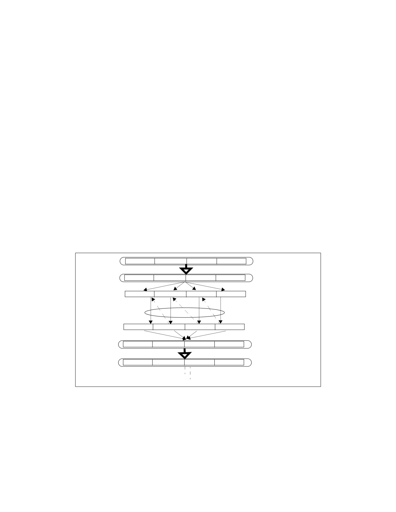
GENERAL OPTIMIZATION GUIDELINES
• The can user insert pragmas to help the compiler realize that it can vectorize the code.
• The user can write SIMD code explicitly using intrinsics and C++ classes.
To help enable the compiler to generate SIMD code, avoid global pointers and global variables. These
issues may be less troublesome if all modules are compiled simultaneously, and whole-program optimi-
zation is used.
User/Source Coding Rule 2. (H impact, M generality) Use the smallest possible floating-point or
SIMD data type, to enable more parallelism with the use of a (longer) SIMD vector. For example, use
single precision instead of double precision where possible.
User/Source Coding Rule 3. (M impact, ML generality) Arrange the nesting of loops so that the
innermost nesting level is free of inter-iteration dependencies. Especially avoid the case where the
store of data in an earlier iteration happens lexically after the load of that data in a future iteration,
something which is called a lexically backward dependence.
The integer part of the SIMD instruction set extensions cover 8-bit,16-bit and 32-bit operands. Not all
SIMD operations are supported for 32 bits, meaning that some source code will not be able to be vector-
ized at all unless smaller operands are used.
User/Source Coding Rule 4. (M impact, ML generality) Avoid the use of conditional branches
inside loops and consider using SSE instructions to eliminate branches.
User/Source Coding Rule 5. (M impact, ML generality) Keep induction (loop) variable expressions
simple.
3.5.4
Optimization of Partially Vectorizable Code
Frequently, a program contains a mixture of vectorizable code and some routines that are non-vectoriz-
able. A common situation of partially vectorizable code involves a loop structure which include mixtures
of vectorized code and unvectorizable code. This situation is depicted in Figure 3-2.
Packed SIMD Instruction
Unpacking
Unvectorizable Code
Serial Routine
Packing
Packed SIMD Instruction
Figure 3-2. Generic Program Flow of Partially Vectorized Code
It generally consists of five stages within the loop:
• Prolog.
• Unpacking vectorized data structure into individual elements.
• Calling a unvectorizable routine to process each element serially.
• Packing individual result into vectorized data structure.
• Epilogue.
Ref#: 248966-048
3-35

GENERAL OPTIMIZATION GUIDELINES
This section discusses techniques that can reduce the cost and bottleneck associated with the
packing/unpacking stages in these partially vectorize code.
Example 3-27 shows a reference code template that is representative of partially vectorizable coding
situations that also experience performance issues. The unvectorizable portion of code is represented
generically by a sequence of calling a serial function named “foo” multiple times. This generic example is
referred to as “shuffle with store forwarding”, because the problem generally involves an unpacking stage
that shuffles data elements between register and memory, followed by a packing stage that can experi-
ence store forwarding issue.
There are more than one useful techniques that can reduce the store-forwarding bottleneck between the
serialized portion and the packing stage. The following sub-sections presents alternate techniques to
deal with the packing, unpacking, and parameter passing to serialized function calls.
Example 3-27. Reference Code Template for Partially Vectorizable Program
// Prolog
///////////////////////////////
push ebp
mov ebp, esp
// Unpacking ////////////////////////////
sub ebp, 32
and ebp, 0xfffffff0
movaps [ebp], xmm0
// Serial operations on components ///////
sub ebp, 4
mov eax, [ebp+4]
mov [ebp], eax
call foo
mov [ebp+16+4], eax
mov eax, [ebp+8]
mov [ebp], eax
call foo
mov [ebp+16+4+4], eax
mov eax, [ebp+12]
mov [ebp], eax
call foo
mov [ebp+16+8+4], eax
mov eax, [ebp+12+4]
mov [ebp], eax
call foo
mov [ebp+16+12+4], eax
// Packing ///////////////////////////////
movaps xmm0, [ebp+16+4]
// Epilog ////////////////////////////////
pop ebp
ret
Ref#: 248966-048
3-36

GENERAL OPTIMIZATION GUIDELINES
3.5.4.1
Alternate Packing Techniques
The packing method implemented in the reference code of Example 3-27 will experience delay as it
assembles 4 doubleword result from memory into an XMM register due to store-forwarding restrictions.
Three alternate techniques for packing, using different SIMD instruction to assemble contents in XMM
registers are shown in Example 3-28. All three techniques avoid store-forwarding delay by satisfying the
restrictions on data sizes between a preceding store and subsequent load operations.
Example 3-28. Three Alternate Packing Methods for Avoiding Store Forwarding Difficulty
Packing Method 1
Packing Method 2
Packing Method 3
movd xmm0, [ebp+16+4]
movd xmm0, [ebp+16+4]
movd xmm0, [ebp+16+4]
movd xmm1, [ebp+16+8]
movd xmm1, [ebp+16+8]
movd xmm1, [ebp+16+8]
movd xmm2, [ebp+16+12]
movd xmm2, [ebp+16+12]
movd xmm2, [ebp+16+12]
movd xmm3, [ebp+12+16+4]
movd xmm3, [ebp+12+16+4]
movd xmm3, [ebp+12+16+4]
punpckldq xmm0, xmm1
psllq xmm3, 32
movlhps xmm1,xmm3
punpckldq xmm2, xmm3
orps xmm2, xmm3
psllq xmm1, 32
punpckldq xmm0, xmm2
psllq xmm1, 32
movlhps xmm0, xmm2
orps xmm0, xmm1movlhps xmm0, xmm2
orps xmm0, xmm1
3.5.4.2
Simplifying Result Passing
In Example 3-27, individual results were passed to the packing stage by storing to contiguous memory
locations. Instead of using memory spills to pass four results, result passing may be accomplished by
using either one or more registers. Using registers to simplify result passing and reduce memory spills
can improve performance by varying degrees depending on the register pressure at runtime.
Example 3-29 shows the coding sequence that uses four extra XMM registers to reduce all memory spills
of passing results back to the parent routine. However, software must observe the following conditions
when using this technique:
• There is no register shortage.
• If the loop does not have many stores or loads but has many computations, this technique does not
help performance. This technique adds work to the computational units, while the store and loads
ports are idle.
Example 3-29. Using Four Registers to Reduce Memory Spills and Simplify Result Passing
mov eax, [ebp+4]
mov [ebp], eax
call foo
movd xmm0, eax
mov eax, [ebp+8]
mov [ebp], eax
call foo
movd xmm1, eax
Ref#: 248966-048
3-37

GENERAL OPTIMIZATION GUIDELINES
Example 3-29. Using Four Registers to Reduce Memory Spills and Simplify Result Passing (Contd.)
mov eax, [ebp+12]
mov [ebp], eax
call foo
movd xmm2, eax
mov eax, [ebp+12+4]
mov [ebp], eax
call foo
movd xmm3, eax
3.5.4.3
Stack Optimization
In Example 3-27, an input parameter was copied in turn onto the stack and passed to the unvectorizable
routine for processing. The parameter passing from consecutive memory locations can be simplified by a
technique shown in Example 3-30.
Example 3-30. Stack Optimization Technique to Simplify Parameter Passing
call foo
mov [ebp+16], eax
add ebp, 4
call foo
mov [ebp+16], eax
add ebp, 4
call foo
mov [ebp+16], eax
add ebp, 4
call foo
Stack Optimization can only be used when:
• The serial operations are function calls. The function “foo” is declared as: INT FOO(INT A). The
parameter is passed on the stack.
• The order of operation on the components is from last to first.
Note the call to FOO and the advance of EDP when passing the vector elements to FOO one by one from
last to first.
3.5.4.4
Tuning Considerations
Tuning considerations for situations represented by looping of Example 3-27 include:
• Applying one of more of the following combinations:
— Choose an alternate packing technique.
— Consider a technique to simply result-passing.
— Consider the stack optimization technique to simplify parameter passing.
• Minimizing the average number of cycles to execute one iteration of the loop.
• Minimizing the per-iteration cost of the unpacking and packing operations.
Ref#: 248966-048
3-38

GENERAL OPTIMIZATION GUIDELINES
The speed improvement by using the techniques discussed in this section will vary, depending on the
choice of combinations implemented and characteristics of the non-vectorizable routine. For example, if
the routine “foo” is short (representative of tight, short loops), the per-iteration cost of
unpacking/packing tend to be smaller than situations where the non-vectorizable code contain longer
operation or many dependencies. This is because many iterations of short, tight loop can be in flight in
the execution core, so the per-iteration cost of packing and unpacking is only partially exposed and
appear to cause very little performance degradation.
Evaluation of the per-iteration cost of packing/unpacking should be carried out in a methodical manner
over a selected number of test cases, where each case may implement some combination of the tech-
niques discussed in this section. The per-iteration cost can be estimated by:
• Evaluating the average cycles to execute one iteration of the test case.
• Evaluating the average cycles to execute one iteration of a base line loop sequence of
non-vectorizable code.
Example 3-31 shows the base line code sequence that can be used to estimate the average cost of a loop
that executes non-vectorizable routines.
Example 3-31. Base Line Code Sequence to Estimate Loop Overhead
push ebp
mov ebp, esp
sub ebp, 4
mov [ebp], edi
call foo
mov [ebp], edi
call foo
mov [ebp], edi
call foo
mov [ebp], edi
call foo
add ebp, 4
pop ebp
ret
The average per-iteration cost of packing/unpacking can be derived from measuring the execution times
of a large number of iterations by:
((Cycles to run TestCase) - (Cycles to run equivalent baseline sequence) ) / (Iteration count).
For example, using a simple function that returns an input parameter (representative of tight, short
loops), the per-iteration cost of packing/unpacking may range from slightly more than 7 cycles (the
shuffle with store forwarding case, Example 3-27) to ~0.9 cycles (accomplished by several test cases).
Across 27 test cases (consisting of one of the alternate packing methods, no result-simplification/simpli-
fication of either 1 or 4 results, no stack optimization or with stack optimization), the average per-itera-
tion cost of packing/unpacking is about 1.7 cycles.
Generally speaking, packing method 2 and 3 (see Example 3-28) tend to be more robust than packing
method 1; the optimal choice of simplifying 1 or 4 results will be affected by register pressure of the
runtime and other relevant microarchitectural conditions.
Note that the numeric discussion of per-iteration cost of packing/packing is illustrative only. It will vary
with test cases using a different base line code sequence and will generally increase if the non-vectoriz-
Ref#: 248966-048
3-39
GENERAL OPTIMIZATION GUIDELINES
able routine requires longer time to execute because the number of loop iterations that can reside in
flight in the execution core decreases.
3.6
OPTIMIZING MEMORY ACCESSES
This section discusses guidelines for optimizing code and data memory accesses. The most important
recommendations are:
• Execute load and store operations within available execution bandwidth.
• Enable forward progress of speculative execution.
• Enable store forwarding to proceed.
• Align data, paying attention to data layout and stack alignment.
• Place code and data on separate pages.
• Enhance data locality.
• Use prefetching and cacheability control instructions.
• Enhance code locality and align branch targets.
• Take advantage of write combining.
3.6.1
Load and Store Execution Bandwidth
Typically, loads and stores are the most frequent operations in a workload, up to 40% of the instructions
in a workload carrying load or store intent are not uncommon. Each generation of microarchitecture
provides multiple buffers to support executing load and store operations while there are instructions in
flight. These buffers were comprised of 128-bit wide entries for the Sandy Bridge and Ivy Bridge microar-
chitectures. The size was increased to 256-bit in Haswell, Broadwell and Skylake Client microarchitec-
tures; and to 512-bit in Skylake Server, Cascade Lake, Cascade Lake Advanced Performance, and Ice
Lake Client microarchitectures. To maximize performance, it is best to use the largest width available in
the platform.
3.6.1.1
Making Use of Load Bandwidth in Sandy Bridge Microarchitecture
While prior microarchitecture has one load port (port 2), Sandy Bridge microarchitecture can load from
port 2 and port 3. Thus two load operations can be performed every cycle and doubling the load
throughput of the code. This improves code that reads a lot of data and does not need to write out results
to memory very often (Port 3 also handles store-address operation). To exploit this bandwidth, the data
has to stay in the L1 data cache or it should be accessed sequentially, enabling the hardware prefetchers
to bring the data to the L1 data cache in time.
Consider the following C code example of adding all the elements of an array:
int buff[BUFF_SIZE];
int sum = 0;
for (i=0;i<BUFF_SIZE;i++){
sum+=buff[i];
}
Alternative 1 is the assembly code generated by the Intel compiler for this C code, using the optimization
flag for Nehalem microarchitecture. The compiler vectorizes execution using Intel SSE instructions. In
this code, each ADD operation uses the result of the previous ADD operation. This limits the throughput
to one load and ADD operation per cycle. Alternative 2 is optimized for Sandy Bridge microarchitecture
by enabling it to use the additional load bandwidth. The code removes the dependency among ADD oper-
Ref#: 248966-048
3-40

GENERAL OPTIMIZATION GUIDELINES
ations, by using two registers to sum the array values. Two load and two ADD operations can be executed
every cycle.
Example 3-32. Optimizing for Load Port Bandwidth in Sandy Bridge Microarchitecture
Reduce register dependency allow two load port to supply
Register dependency inhibits PADD execution
PADD execution
xor
eax, eax
xor
eax, eax
pxor
xmm0, xmm0
pxor
xmm0, xmm0
lea
rsi, buff
pxor
xmm1, xmm1
lea
rsi, buff
loop_start:
loop_start:
paddd xmm0, [rsi+4*rax]
paddd
xmm0, [rsi+4*rax]
paddd xmm0, [rsi+4*rax+16]
paddd
xmm1, [rsi+4*rax+16]
paddd xmm0, [rsi+4*rax+32]
paddd
xmm0, [rsi+4*rax+32]
paddd xmm0, [rsi+4*rax+48]
paddd
xmm1, [rsi+4*rax+48]
paddd xmm0, [rsi+4*rax+64]
paddd
xmm0, [rsi+4*rax+64]
paddd xmm0, [rsi+4*rax+80]
paddd
xmm1, [rsi+4*rax+80]
paddd xmm0, [rsi+4*rax+96]
paddd
xmm0, [rsi+4*rax+96]
paddd xmm0, [rsi+4*rax+112]
paddd
xmm1, [rsi+4*rax+112]
add eax, 32
add eax, 32
cmp eax, BUFF_SIZE
cmp eax, BUFF_SIZE
jl loop_start
jl loop_start
sum_partials:
sum_partials:
movdqa xmm1, xmm0
paddd
xmm0, xmm1
psrldq xmm1, 8
movdqa xmm1, xmm0
paddd xmm0, xmm1
psrldq
xmm1, 8
movdqa xmm2, xmm0
paddd
xmm0, xmm1
psrldq xmm2, 4
movdqa xmm2, xmm0
paddd xmm0, xmm2
psrldq
xmm2, 4
movd
[sum], xmm0
paddd xmm0, xmm2
movd
[sum], xmm0
3.6.1.2
L1D Cache Latency in Sandy Bridge Microarchitecture
Load latency from L1D cache may vary. The best case if 4 cycles, which apply to load operations to
general purpose registers using one of the following:
• One register.
• A base register plus an offset that is smaller than 2048.
Consider the pointer-chasing code example in Example 3-33.
Ref#: 248966-048
3-41

GENERAL OPTIMIZATION GUIDELINES
Example 3-33. Index versus Pointers in Pointer-Chasing Code
Traversing through indexes
Traversing through pointers
// C code example
// C code example
index = buffer.m_buff[index].next_index;
node = node->pNext;
// ASM example
// ASM example
loop:
loop:
shl rbx, 6
mov rdx, [rdx]
mov rbx, 0x20(rbx+rcx)
dec rax
dec rax
cmp rax, -1
cmp rax, -1
jne loop
jne loop
The left side implements pointer chasing via traversing an index. Compiler then generates the code
shown below addressing memory using base+index with an offset. The right side shows compiler gener-
ated code from pointer de-referencing code and uses only a base register.
The code on the right side is faster than the left side across Sandy Bridge microarchitecture and prior
microarchitecture. However the code that traverses index will be slower on Sandy Bridge microarchitec-
ture relative to prior microarchitecture.
3.6.1.3
Handling L1D Cache Bank Conflict
In the Sandy Bridge microarchitecture, the internal organization of the L1D cache may manifest a situa-
tion when two load micro-ops whose addresses have a bank conflict. When a bank conflict is present
between two load operations, the more recent one will be delayed until the conflict is resolved. A bank
conflict happens when two simultaneous load operations have the same bit 2-5 of their linear address but
they are not from the same set in the cache (bits 6 - 12).
Bank conflicts should be handled only if the code is bound by load bandwidth. Some do not cause any
performance degradation since they are hidden by other performance limiters. Eliminating such bank
conflicts does not improve performance.
The L1D cache bank conflict issue does not apply to Haswell microarchitecture.
The following example demonstrates bank conflict and how to modify the code and avoid them. It uses
two source arrays with a size that is a multiple of cache line size. When loading an element from A and
the counterpart element from B the elements have the same offset in their cache lines; therefore, a bank
conflict may happen.
Ref#: 248966-048
3-42

GENERAL OPTIMIZATION GUIDELINES
Example 3-34. Example of Bank Conflicts in L1D Cache and Remedy
int A[128];
int B[128];
int C[128];
for (i=0;i<128;i+=4){
C[i]=A[i]+B[i];
the loads from A[i] and B[i] collide
C[i+1]=A[i+1]+B[i+1];
C[i+2]=A[i+2]+B[i+2];
C[i+3]=A[i+3]+B[i+3];
}
// Code with Bank Conflicts
// Code without Bank Conflicts
xor rcx, rcx
xor rcx, rcx
lea r11, A
lea r11, A
lea r12, B
lea r12, B
lea r13, C
lea r13, C
loop:
loop:
lea esi, [rcx*4]
lea esi, [rcx*4]
movsxd rsi, esi
movsxd rsi, esi
mov edi, [r11+rsi*4]
mov edi, [r11+rsi*4]
add edi, [r12+rsi*4]
mov r8d, [r11+rsi*4+4]
mov r8d, [r11+rsi*4+4]
add edi, [r12+rsi*4]
add r8d, [r12+rsi*4+4]
add r8d, [r12+rsi*4+4]
mov r9d, [r11+rsi*4+8]
mov r9d, [r11+rsi*4+8]
add r9d, [r12+rsi*4+8]
mov r10d, [r11+rsi*4+12]
mov r10d, [r11+rsi*4+12]
add r9d, [r12+rsi*4+8]
add r10d, [r12+rsi*4+12]
add r10d, [r12+rsi*4+12]
mov [r13+rsi*4], edi
inc ecx
inc ecx
mov [r13+rsi*4], edi
mov [r13+rsi*4+4], r8d
mov [r13+rsi*4+4], r8d
mov [r13+rsi*4+8], r9d
mov [r13+rsi*4+8], r9d
mov [r13+rsi*4+12], r10d
mov [r13+rsi*4+12], r10d
cmp ecx, LEN
cmp ecx, LEN
jb loop
jb loop
Bank conflicts may occur with the introduction of the third load port in the Golden Cove microarchitec-
ture. In this microarchitecture, conflicts happen between three loads with the same bits 2-5 of their
linear address even if they access the same set of the cache. Up to two loads can access the same cache
bank without a conflict; however, a third load accessing the same bank must be delayed. The bank
conflicts do not apply to 512-bit wide loads because their bandwidth is limited to two per cycle.
Recommendation: In the Golden Cove microarchitecture, bank conflicts often happen when multiple
loads access the same memory location. Whenever possible, avoid reading the same memory location
within a tight loop or using multiple load operations. Commonly used memory locations are better kept
in the registers to prevent potential bank conflict penalty.
Ref#: 248966-048
3-43

GENERAL OPTIMIZATION GUIDELINES
3.6.2
Minimize Register Spills
When a piece of code has more live variables than the processor can keep in general purpose registers,
a common method is to hold some of the variables in memory. This method is called register spill. The
effect of L1D cache latency can negatively affect the performance of this code. The effect can be more
pronounced if the address of register spills uses the slower addressing modes.
One option is to spill general purpose registers to XMM registers. This method is likely to improve perfor-
mance also on previous processor generations. The following example shows how to spill a register to an
XMM register rather than to memory.
Example 3-35. Using XMM Register in Lieu of Memory for Register Spills
Register spills into memory
Register spills into XMM
loop:
movq xmm4, [rsp+0x18]
mov rdx, [rsp+0x18]
mov rcx, 0x10
movdqa xmm0, [rdx]
movq xmm5, rcx
movdqa xmm1, [rsp+0x20]
loop:
pcmpeqd xmm1, xmm0
movq rdx, xmm4
pmovmskb eax, xmm1
movdqa xmm0, [rdx]
test eax, eax
movdqa xmm1, [rsp+0x20]
jne end_loop
pcmpeqd xmm1, xmm0
movzx rcx, [rbx+0x60]
pmovmskb eax, xmm1
test eax, eax
jne end_loop
movzx rcx, [rbx+0x60]
add qword ptr[rsp+0x18], 0x10
padd xmm4, xmm5
add rdi, 0x4
add rdi, 0x4
movzx rdx, di
movzx rdx, di
sub rcx, 0x4
sub rcx, 0x4
add rsi, 0x1d0
add rsi, 0x1d0
cmp rdx, rcx
cmp rdx, rcx
jle loop
jle loop
3.6.3
Enhance Speculative Execution and Memory Disambiguation
Prior to Intel Core microarchitecture, when code contains both stores and loads, the loads cannot be
issued before the address of the older stores is known. This rule ensures correct handling of load depen-
dencies on preceding stores.
The Intel Core microarchitecture contains a mechanism that allows some loads to be executed specula-
tively in the presence of older unknown stores. The processor later checks if the load address overlapped
with an older store whose address was unknown at the time the load executed. If the addresses do
overlap, then the processor re-executes the load and all succeeding instructions.
Example 3-36 illustrates a situation that the compiler cannot be sure that “Ptr->Array” does not change
during the loop. Therefore, the compiler cannot keep “Ptr->Array” in a register as an invariant and must
read it again in every iteration. Although this situation can be fixed in software by a rewriting the code to
require the address of the pointer is invariant, memory disambiguation improves performance without
rewriting the code.
Ref#: 248966-048
3-44

GENERAL OPTIMIZATION GUIDELINES
Example 3-36. Loads Blocked by Stores of Unknown Address
C code
Assembly sequence
struct AA {
nullify_loop:
AA ** array;
mov dword ptr [eax], 0
};
mov edx, dword ptr [edi]
void nullify_array ( AA *Ptr, DWORD Index, AA *ThisPtr )
sub ecx, 4
{
cmp dword ptr [ecx+edx], esi
while ( Ptr->Array[--Index] != ThisPtr )
lea eax, [ecx+edx]
{
jne nullify_loop
Ptr->Array[Index] = NULL ;
} ;
} ;
It is possible to disable speculative store bypass with the IA32_SPEC_CTRL.SSBD MSR.
Additional information on this topic can be found on the Software Security Guidance page.
3.6.4
Store Forwarding
The processor’s memory system only sends stores to memory (including cache) after store retirement.
However, store data can be forwarded from a store to a subsequent load from the same address to give
a much shorter store-load latency.
There are two kinds of requirements for store forwarding. If these requirements are violated, store
forwarding cannot occur and the load must get its data from the cache (so the store must write its data
back to the cache first). This incurs a penalty that is largely related to pipeline depth of the underlying
micro-architecture.
The first requirement pertains to the size and alignment of the store-forwarding data. This restriction is
likely to have high impact on overall application performance. Typically, a performance penalty due to
violating this restriction can be prevented. The store-to-load forwarding restrictions vary from one
microarchitecture to another. Several examples of coding pitfalls that cause store-forwarding stalls and
solutions to these pitfalls are discussed in detail in Section 3.6.4.1 The second requirement is the avail-
ability of data, discussed in Section 3.6.4.2 A good practice is to eliminate redundant load operations.
It may be possible to keep a temporary scalar variable in a register and never write it to memory. Gener-
ally, such a variable must not be accessible using indirect pointers. Moving a variable to a register elimi-
nates all loads and stores of that variable and eliminates potential problems associated with store
forwarding. However, it also increases register pressure.
Load instructions tend to start chains of computation. Since the out-of-order engine is based on data
dependence, load instructions play a significant role in the engine’s ability to execute at a high rate. Elim-
inating loads should be given a high priority.
If a variable does not change between the time when it is stored and the time when it is used again, the
register that was stored can be copied or used directly. If register pressure is too high, or an unseen func-
tion is called before the store and the second load, it may not be possible to eliminate the second load.
Assembly/Compiler Coding Rule 40. (H impact, M generality) Pass parameters in registers
instead of on the stack where possible. Passing arguments on the stack requires a store followed by a
reload. While this sequence is optimized in hardware by providing the value to the load directly from
the memory order buffer without the need to access the data cache if permitted by store-forwarding
restrictions, floating-point values incur a significant latency in forwarding. Passing floating-point
arguments in (preferably XMM) registers should save this long latency operation.
Parameter passing conventions may limit the choice of which parameters are passed in registers which
are passed on the stack. However, these limitations may be overcome if the compiler has control of the
compilation of the whole binary (using whole-program optimization).
Ref#: 248966-048
3-45

GENERAL OPTIMIZATION GUIDELINES
3.6.4.1
Store-to-Load-Forwarding Restriction on Size and Alignment
Data size and alignment restrictions for store-forwarding apply to processors based on Intel Core
microarchitecture, Intel Core 2 Duo, Intel Core Solo and Pentium M processors. The performance penalty
for violating store-forwarding restrictions is less for shorter-pipelined machines.
Store-forwarding restrictions vary with each microarchitecture. The following rules help satisfy size and
alignment restrictions for store forwarding:
Assembly/Compiler Coding Rule 41. (H impact, M generality) A load that forwards from a store
must have the same address start point and therefore the same alignment as the store data.
Assembly/Compiler Coding Rule 42. (H impact, M generality) The data of a load which is
forwarded from a store must be completely contained within the store data.
A load that forwards from a store must wait for the store’s data to be written to the store buffer before
proceeding, but other, unrelated loads need not wait.
Assembly/Compiler Coding Rule 43. (H impact, ML generality) If it is necessary to extract a
non-aligned portion of stored data, read out the smallest aligned portion that completely contains the
data and shift/mask the data as necessary. This is better than incurring the penalties of a failed
store-forward.
Assembly/Compiler Coding Rule 44. (MH impact, ML generality) Avoid several small loads after
large stores to the same area of memory by using a single large read and register copies as needed.
Example 3-37 depicts several store-forwarding situations in which small loads follow large stores. The
first three load operations illustrate the situations described in Rule 44. However, the last load operation
gets data from store-forwarding without problem.
Example 3-37. Situations Showing Small Loads After Large Store
mov [EBP],‘abcd’
mov AL, [EBP]
; Not blocked - same alignment
mov BL, [EBP + 1]
; Blocked
mov CL, [EBP + 2]
; Blocked
mov DL, [EBP + 3]
; Blocked
mov AL, [EBP]
; Not blocked - same alignment
; n.b. passes older blocked loads
Example 3-38 illustrates a store-forwarding situation in which a large load follows several small stores.
The data needed by the load operation cannot be forwarded because all of the data that needs to be
forwarded is not contained in the store buffer. Avoid large loads after small stores to the same area of
memory.
Example 3-38. Non-forwarding Example of Large Load After Small Store
mov [EBP], ‘a’
mov [EBP + 1], ‘b’
mov [EBP + 2], ‘c’
mov [EBP + 3], ‘d’
mov EAX, [EBP]
; Blocked
; The first 4 small store can be consolidated into
; a single DWORD store to prevent this non-forwarding
; situation.
Ref#: 248966-048
3-46

GENERAL OPTIMIZATION GUIDELINES
Example 3-39 illustrates a stalled store-forwarding situation that may appear in compiler generated
code. Sometimes a compiler generates code similar to that shown in Example 3-39 to handle a spilled
byte to the stack and convert the byte to an integer value.
Example 3-39. A Non-forwarding Situation in Compiler Generated Code
mov DWORD PTR [esp+10h], 00000000h
mov BYTE PTR [esp+10h], bl
mov eax, DWORD PTR [esp+10h] ; Stall
and eax, 0xff
; Converting back to byte value
Example 3-40 offers two alternatives to avoid the non-forwarding situation shown in Example 3-39.
Example 3-40. Two Ways to Avoid Non-forwarding Situation in Example 3-39
; A. Use MOVZ instruction to avoid large load after small
; store, when spills are ignored.
movz eax, bl
; Replaces the last three instructions
; B. Use MOVZ instruction and handle spills to the stack
mov DWORD PTR [esp+10h], 00000000h
mov BYTE PTR [esp+10h], bl
movz eax, BYTE PTR [esp+10h]
; Not blocked
When moving data that is smaller than 64 bits between memory locations, 64-bit or 128-bit SIMD
register moves are more efficient (if aligned) and can be used to avoid unaligned loads. Although
floating-point registers allow the movement of 64 bits at a time, floating-point instructions should not be
used for this purpose, as data may be inadvertently modified.
As an additional example, consider the cases in Example 3-41.
Example 3-41. Large and Small Load Stalls
; A. Large load stall
mov
mem, eax
; Store dword to address “MEM"
mov
mem + 4, ebx
; Store dword to address “MEM + 4"
fld
mem
; Load qword at address “MEM", stalls
; B. Small Load stall
fstp mem
; Store qword to address “MEM"
mov bx, mem+2
; Load word at address “MEM + 2", stalls
mov cx, mem+4
; Load word at address “MEM + 4", stalls
In the first case (A), there is a large load after a series of small stores to the same area of memory
(beginning at memory address MEM). The large load will stall.
The FLD must wait for the stores to write to memory before it can access all the data it requires. This stall
can also occur with other data types (for example, when bytes or words are stored and then words or
doublewords are read from the same area of memory).
In the second case (B), there is a series of small loads after a large store to the same area of memory
(beginning at memory address MEM). The small loads will stall.
The word loads must wait for the quadword store to write to memory before they can access the data
they require. This stall can also occur with other data types (for example, when doublewords or words
are stored and then words or bytes are read from the same area of memory). This can be avoided by
moving the store as far from the loads as possible.
Ref#: 248966-048
3-47

GENERAL OPTIMIZATION GUIDELINES
Store forwarding restrictions for processors based on Intel Core microarchitecture is listed in Table 3-4.
Table 3-4. Store Forwarding Restrictions of Processors Based on Intel Core Microarchitecture
Width of
Store Forwarding
Store Alignment
Load Alignment (byte)
Width of Load (bits)
Store (bits)
Restriction
To Natural size
16
word aligned
8, 16
not stalled
To Natural size
16
not word aligned
8
stalled
To Natural size
32
dword aligned
8, 32
not stalled
To Natural size
32
not dword aligned
8
stalled
To Natural size
32
word aligned
16
not stalled
To Natural size
32
not word aligned
16
stalled
To Natural size
64
qword aligned
8, 16, 64
not stalled
To Natural size
64
not qword aligned
8, 16
stalled
To Natural size
64
dword aligned
32
not stalled
To Natural size
64
not dword aligned
32
stalled
To Natural size
128
dqword aligned
8, 16, 128
not stalled
To Natural size
128
not dqword aligned
8, 16
stalled
To Natural size
128
dword aligned
32
not stalled
To Natural size
128
not dword aligned
32
stalled
To Natural size
128
qword aligned
64
not stalled
To Natural size
128
not qword aligned
64
stalled
Unaligned, start byte 1
32
byte 0 of store
8, 16, 32
not stalled
Unaligned, start byte 1
32
not byte 0 of store
8, 16
stalled
Unaligned, start byte 1
64
byte 0 of store
8, 16, 32
not stalled
Unaligned, start byte 1
64
not byte 0 of store
8, 16, 32
stalled
Unaligned, start byte 1
64
byte 0 of store
64
stalled
Unaligned, start byte 7
32
byte 0 of store
8
not stalled
Unaligned, start byte 7
32
not byte 0 of store
8
not stalled
Unaligned, start byte 7
32
don’t care
16, 32
stalled
Unaligned, start byte 7
64
don’t care
16, 32, 64
stalled
3.6.4.2
Store-Forwarding Restriction on Data Availability
The value to be stored must be available before the load operation can be completed. If this restriction is
violated, the execution of the load will be delayed until the data is available. This delay causes some
execution resources to be used unnecessarily, and that can lead to sizable but non-deterministic delays.
However, the overall impact of this problem is much smaller than that from violating size and alignment
requirements.
In modern microarchitectures, hardware predicts when loads are dependent on and get their data
forwarded from preceding stores. These predictions can significantly improve performance. However, if a
load is scheduled too soon after the store it depends on or if the generation of the data to be stored is
delayed, there can be a significant penalty.
There are several cases in which data is passed through memory, and the store may need to be sepa-
rated from the load:
• Spills, save and restore registers in a stack frame.
• Parameter passing.
• Global and volatile variables.
Ref#: 248966-048
3-48

GENERAL OPTIMIZATION GUIDELINES
• Type conversion between integer and floating-point.
• When compilers do not analyze code that is inlined, forcing variables that are involved in the interface
with inlined code to be in memory, creating more memory variables and preventing the elimination of
redundant loads.
Assembly/Compiler Coding Rule 45. (H impact, MH generality) Where it is possible to do so
without incurring other penalties, prioritize the allocation of variables to registers, as in register
allocation and for parameter passing, to minimize the likelihood and impact of store-forwarding
problems. Try not to store-forward data generated from a long latency instruction - for example, MUL
or DIV. Avoid store-forwarding data for variables with the shortest store-load distance. Avoid
store-forwarding data for variables with many and/or long dependence chains, and especially avoid
including a store forward on a loop-carried dependence chain.
Example 3-42 shows an example of a loop-carried dependence chain.
Example 3-42. Loop-Carried Dependence Chain
for ( i = 0; i < MAX; i++ ) {
a[i] = b[i] * foo;
foo = a[i] / 3;
}
// foo is a loop-carried dependence.
Assembly/Compiler Coding Rule 46. (M impact, MH generality) Calculate store addresses as
early as possible to avoid having stores block loads.
3.6.5
Data Layout Optimizations
User/Source Coding Rule 6. (H impact, M generality) Pad data structures defined in the source
code so that every data element is aligned to a natural operand size address boundary.
If the operands are packed in a SIMD instruction, align to the packed element size (64-bit or 128-bit).
Align data by providing padding inside structures and arrays. Programmers can reorganize structures and
arrays to minimize the amount of memory wasted by padding. However, compilers might not have this
freedom. The C programming language, for example, specifies the order in which structure elements are
allocated in memory. For more information, see Section 5.4.
Example 3-43 shows how a data structure could be rearranged to reduce its size.
Example 3-43. Rearranging a Data Structure
struct unpacked { /* Fits in 20 bytes due to padding */
int
a;
char
b;
int
c;
char
d;
int
e;
};
struct packed { /* Fits in 16 bytes */
int
a;
int
c;
int
e;
char
b;
char
d;
}
Cache line size of 64 bytes can impact streaming applications (for example, multimedia). These refer-
ence and use data only once before discarding it. Data accesses which sparsely utilize the data within a
Ref#: 248966-048
3-49

GENERAL OPTIMIZATION GUIDELINES
cache line can result in less efficient utilization of system memory bandwidth. For example, arrays of
structures can be decomposed into several arrays to achieve better packing, as shown in Example 3-44.
Example 3-44. Decomposing an Array
struct {
/* 1600 bytes */
int a, c, e;
char b, d;
} array_of_struct [100];
struct {
/* 1400 bytes */
int a[100], c[100], e[100];
char b[100], d[100];
} struct_of_array;
struct {
/* 1200 bytes */
int a, c, e;
} hybrid_struct_of_array_ace[100];
struct {
/* 200 bytes */
char b, d;
} hybrid_struct_of_array_bd[100];
The efficiency of such optimizations depends on usage patterns. If the elements of the structure are all
accessed together but the access pattern of the array is random, then ARRAY_OF_STRUCT avoids unnec-
essary prefetch even though it wastes memory.
However, if the access pattern of the array exhibits locality (for example, if the array index is being swept
through) then processors with hardware prefetchers will prefetch data from STRUCT_OF_ARRAY, even if
the elements of the structure are accessed together.
When the elements of the structure are not accessed with equal frequency, such as when element A is
accessed ten times more often than the other entries, then STRUCT_OF_ARRAY not only saves memory,
but it also prevents fetching unnecessary data items B, C, D, and E.
Using STRUCT_OF_ARRAY also enables the use of the SIMD data types by the programmer and the
compiler.
Note that STRUCT_OF_ARRAY can have the disadvantage of requiring more independent memory stream
references. This can require the use of more prefetches and additional address generation calculations.
It can also have an impact on DRAM page access efficiency. An alternative, HYBRID_STRUCT_OF_ARRAY
blends the two approaches. In this case, only 2 separate address streams are generated and referenced:
1 for HYBRID_STRUCT_OF_ARRAY_ACE and 1 for HYBRID_STRUCT_OF_ARRAY_BD. The second alter-
ative also prevents fetching unnecessary data — assuming that (1) the variables A, C and E are always
used together, and (2) the variables B and D are always used together, but not at the same time as A, C
and E.
The hybrid approach ensures:
• Simpler/fewer address generations than STRUCT_OF_ARRAY.
• Fewer streams, which reduces DRAM page misses.
• Fewer prefetches due to fewer streams.
• Efficient cache line packing of data elements that are used concurrently.
Assembly/Compiler Coding Rule 47. (H impact, M generality) Try to arrange data structures
such that they permit sequential access.
If the data is arranged into a set of streams, the automatic hardware prefetcher can prefetch data that
will be needed by the application, reducing the effective memory latency. If the data is accessed in a
Ref#: 248966-048
3-50

GENERAL OPTIMIZATION GUIDELINES
non-sequential manner, the automatic hardware prefetcher cannot prefetch the data. The prefetcher can
recognize up to eight concurrent streams. See Chapter 9 for more information on the hardware
prefetcher.
User/Source Coding Rule 7. (M impact, L generality) Beware of false sharing within a cache line
(64 bytes).
3.6.6
Stack Alignment
Performance penalty of unaligned access to the stack happens when a memory reference splits a cache
line. This means that one out of eight spatially consecutive unaligned quadword accesses is always
penalized, similarly for one out of 4 consecutive, non-aligned double-quadword accesses, etc.
Aligning the stack may be beneficial any time there are data objects that exceed the default stack align-
ment of the system. For example, on 32/64bit Linux, and 64bit Windows, the default stack alignment is
16 bytes, while 32bit Windows is 4 bytes.
Assembly/Compiler Coding Rule 48. (H impact, M generality) Make sure that the stack is aligned
at the largest multi-byte granular data type boundary matching the register width.
Aligning the stack typically requires the use of an additional register to track across a padded area of
unknown amount. There is a trade-off between causing unaligned memory references that spanned
across a cache line and causing extra general purpose register spills.
The assembly level technique to implement dynamic stack alignment may depend on compilers, and
specific OS environment. The reader may wish to study the assembly output from a compiler of interest.
Example 3-45. Examples of Dynamical Stack Alignment
// 32-bit environment
push
ebp ; save ebp
mov
ebp, esp ; ebp now points to incoming parameters
andl
esp, $-<N> ;align esp to N byte boundary
sub
esp, $<stack_size>; reserve space for new stack frame
; parameters must be referenced off of ebp
mov
esp, ebp ; restore esp
pop
ebp ; restore ebp
// 64-bit environment
sub
esp, $<stack_size +N>
mov
r13, $<offset_of_aligned_section_in_stack>
andl
r13, $-<N> ; r13 point to aligned section in stack
;use r13 as base for aligned data
If for some reason it is not possible to align the stack for 64-bits, the routine should access the parameter
and save it into a register or known aligned storage, thus incurring the penalty only once.
3.6.7
Capacity Limits and Aliasing in Caches
There are cases in which addresses with a given stride will compete for some resource in the memory
hierarchy.
Typically, caches are implemented to have multiple ways of set associativity, with each way consisting of
multiple sets of cache lines (or sectors in some cases). Multiple memory references that compete for the
same set of each way in a cache can cause a capacity issue. There are aliasing conditions that apply to
Ref#: 248966-048
3-51
GENERAL OPTIMIZATION GUIDELINES
specific microarchitectures. Note that first-level cache lines are 64 bytes. Thus, the least significant 6 bits
are not considered in alias comparisons.
3.6.8
Mixing Code and Data
The aggressive prefetching and pre-decoding of instructions by Intel processors have two related effects:
• Self-modifying code (SMC) works correctly, according to the Intel architecture processor require-
ments, but incurs a significant performance penalty. Avoid self-modifying code if possible.
• Placing writable data in the code segment might be impossible to distinguish from self-modifying
code. Writable data in the code segment might suffer the same performance penalty as
self-modifying code.
Assembly/Compiler Coding Rule 49. (M impact, L generality) If (hopefully read-only) data must
occur on the same page as code, avoid placing it immediately after an indirect jump. For example,
follow an indirect jump with its mostly likely target, and place the data after an unconditional branch.
Tuning Suggestion 1. In rare cases, a performance problem may be caused by executing data on a
code page as instructions. This is very likely to happen when execution is following an indirect branch
that is not resident in the trace cache. If this is clearly causing a performance problem, try moving the
data elsewhere, or inserting an illegal opcode or a PAUSE instruction immediately after the indirect
branch. Note that the latter two alternatives may degrade performance in some circumstances.
Assembly/Compiler Coding Rule 50. (H impact, L generality) Always put code and data on
separate pages. Avoid self-modifying code wherever possible. If code is to be modified, try to do it all at
once and make sure the code that performs the modifications and the code being modified are on
separate 4-KByte pages or on separate aligned 1-KByte subpages.
3.6.8.1
Self-Modifying Code (SMC)
Self-modifying code (SMC) that ran correctly on Pentium III processors and prior implementations will run
correctly on subsequent implementations. SMC and cross-modifying code (when multiple processors in a
multiprocessor system are writing to a code page) should be avoided when high performance is desired.
Software should avoid writing to a code page in the same 1-KByte subpage that is being executed or
fetching code in the same 2-KByte subpage of that is being written. In addition, sharing a page
containing directly or speculatively executed code with another processor as a data page can trigger an
SMC condition causing the entire pipeline of the machine and the trace cache to be cleared.
Dynamic code need not cause the SMC condition if the code written fills up a data page before that page
is accessed as code. Dynamically-modified code (for example, from target fix-ups) is likely to suffer from
the SMC condition and should be avoided where possible. Avoid the condition by introducing indirect
branches and using data tables on data pages (not code pages) using register-indirect calls.
Ref#: 248966-048
3-52

GENERAL OPTIMIZATION GUIDELINES
3.6.8.2
Position Independent Code
Position independent code often needs to obtain the value of the instruction pointer. Example 3-46a
shows one technique to put the value of IP into the ECX register by issuing a CALL without a matching
RET. Example 3-46b shows an alternative technique to put the value of IP into the ECX register using a
matched pair of CALL/RET.
Example 3-46. Instruction Pointer Query Techniques
a) Using call without return to obtain IP does not corrupt the RSB
call _label; return address pushed is the IP of next instruction
_label:
pop ECX; IP of this instruction is now put into ECX
b) Using matched call/ret pair
call _lblcx;
; ECX now contains IP of this instruction
_lblcx
mov ecx, [esp];
ret
3.6.9
Write Combining
Write combining (WC) improves performance in two ways:
• On a write miss to the first-level cache, it allows multiple stores to the same cache line to occur before
that cache line is read for ownership (RFO) from further out in the cache/memory hierarchy. Then the
rest of line is read, and the bytes that have not been written are combined with the unmodified bytes
in the returned line.
• Write combining allows multiple writes to be assembled and written further out in the cache hierarchy
as a unit. This saves port and bus traffic. Saving traffic is particularly important for avoiding partial
writes to uncached memory.
Processors based on Intel Core microarchitecture have eight write-combining buffers in each core. Begin-
ning with Nehalem microarchitecture, there are 10 buffers available for write-combining. Beginning with
Ice Lake Client microarchitecture, there are 12 buffers available for write-combining.
Assembly/Compiler Coding Rule 51. (H impact, L generality) If an inner loop writes to more than
four arrays (four distinct cache lines), apply loop fission to break up the body of the loop such that only
four arrays are being written to in each iteration of each of the resulting loops.
Write combining buffers are used for stores of all memory types. They are particularly important for
writes to uncached memory: writes to different parts of the same cache line can be grouped into a single,
full-cache-line bus transaction instead of going across the bus (since they are not cached) as several
partial writes. Avoiding partial writes can have a significant impact on bus bandwidth-bound graphics
applications, where graphics buffers are in uncached memory. Separating writes to uncached memory
and writes to writeback memory into separate phases can assure that the write combining buffers can fill
before getting evicted by other write traffic. Eliminating partial write transactions has been found to have
performance impact on the order of 20% for some applications. Because the cache lines are 64 bytes, a
write to the bus for 63 bytes will result in partial bus transactions.
When coding functions that execute simultaneously on two threads, reducing the number of writes that
are allowed in an inner loop will help take full advantage of write-combining store buffers. For
write-combining buffer recommendations for Intel® Hyper-Threading Technology (Intel® HT), see
Chapter 11.
Ref#: 248966-048
3-53

GENERAL OPTIMIZATION GUIDELINES
Store ordering and visibility are also important issues for write combining. When a write to a
write-combining buffer for a previously-unwritten cache line occurs, there will be a read-for-ownership
(RFO). If a subsequent write happens to another write-combining buffer, a separate RFO may be caused
for that cache line. Subsequent writes to the first cache line and write-combining buffer will be delayed
until the second RFO has been serviced to guarantee properly ordered visibility of the writes. If the
memory type for the writes is write-combining, there will be no RFO since the line is not cached, and
there is no such delay. For details on write-combining, see Chapter 9, “Optimizing Cache Usage”
3.6.10 Locality Enhancement
Locality enhancement can reduce data traffic originating from an outer-level sub-system in the
cache/memory hierarchy. This is to address the fact that the access-cost in terms of cycle-count from an
outer level will be more expensive than from an inner level. Typically, the cycle-cost of accessing a given
cache level (or memory system) varies across different microarchitectures, processor implementations,
and platform components. It may be sufficient to recognize the relative data access cost trend by locality
rather than to follow a large table of numeric values of cycle-costs, listed per locality, per processor/plat-
form implementations, etc. The general trend is typically that access cost from an outer sub-system may
be approximately 3-10X more expensive than accessing data from the immediate inner level in the
cache/memory hierarchy, assuming similar degrees of data access parallelism.
Thus locality enhancement should start with characterizing the dominant data traffic locality. Appendix A,
“Application Performance Tools” describes some techniques that can be used to determine the dominant
data traffic locality for any workload.
Even if cache miss rates of the last level cache may be low relative to the number of cache references,
processors typically spend a sizable portion of their execution time waiting for cache misses to be
serviced. Reducing cache misses by enhancing a program’s locality is a key optimization. This can take
several forms:
• Blocking to iterate over a portion of an array that will fit in the cache (with the purpose that
subsequent references to the data-block [or tile] will be cache hit references).
• Loop interchange to avoid crossing cache lines or page boundaries.
• Loop skewing to make accesses contiguous.
Locality enhancement to the last level cache can be accomplished with sequencing the data access
pattern to take advantage of hardware prefetching. This can also take several forms:
• Transformation of a sparsely populated multi-dimensional array into a one-dimension array such that
memory references occur in a sequential, small-stride pattern that is friendly to the hardware
prefetch.
• Optimal tile size and shape selection can further improve temporal data locality by increasing hit
rates into the last level cache and reduce memory traffic resulting from the actions of hardware
prefetching (see Section 9.5.11).
It is important to avoid operations that work against locality-enhancing techniques. Using the lock prefix
heavily can incur large delays when accessing memory, regardless of whether the data is in the cache or
in system memory.
User/Source Coding Rule 8. (H impact, H generality) Optimization techniques such as blocking,
loop interchange, loop skewing, and packing are best done by the compiler. Optimize data structures
either to fit in one-half of the first-level cache or in the second-level cache; turn on loop optimizations
in the compiler to enhance locality for nested loops.
Ref#: 248966-048
3-54

GENERAL OPTIMIZATION GUIDELINES
Optimizing for one-half of the first-level cache will bring the greatest performance benefit in terms of
cycle-cost per data access. If one-half of the first-level cache is too small to be practical, optimize for the
second-level cache. Optimizing for a point in between (for example, for the entire first-level cache) will
likely not bring a substantial improvement over optimizing for the second-level cache.
3.6.11 Non-Temporal Store Bus Traffic
Peak system bus bandwidth is shared by several types of bus activities, including reads (from memory),
reads for ownership (of a cache line), and writes. The data transfer rate for bus write transactions is
higher if 64 bytes are written out to the bus at a time.
Typically, bus writes to Writeback (WB) memory must share the system bus bandwidth with
read-for-ownership (RFO) traffic. Non-temporal stores do not require RFO traffic; they do require care in
managing the access patterns in order to ensure 64 bytes are evicted at once (rather than evicting
several chunks).
Although the data bandwidth of full 64-byte bus writes due to non-temporal stores is twice that of bus
writes to WB memory, transferring several chunks wastes bus request bandwidth and delivers signifi-
cantly lower data bandwidth. This difference is depicted in Examples 3-47 and 3-48.
Example 3-47. Using Non-Temporal Stores and 64-byte Bus Write Transactions
#define STRIDESIZE 256
lea ecx, p64byte_Aligned
mov edx, ARRAY_LEN
xor eax, eax
slloop:
movntps XMMWORD ptr [ecx + eax], xmm0
movntps XMMWORD ptr [ecx + eax+16], xmm0
movntps XMMWORD ptr [ecx + eax+32], xmm0
movntps XMMWORD ptr [ecx + eax+48], xmm0
; 64 bytes is written in one bus transaction
add eax, STRIDESIZE
cmp eax, edx
jl slloop
Example 3-48. On-temporal Stores and Partial Bus Write Transactions
#define STRIDESIZE 256
Lea ecx, p64byte_Aligned
Mov edx, ARRAY_LEN
Xor eax, eax
slloop:
movntps XMMWORD ptr [ecx + eax], xmm0
movntps XMMWORD ptr [ecx + eax+16], xmm0
movntps XMMWORD ptr [ecx + eax+32], xmm0
; Storing 48 bytes results in several bus partial transactions
add eax, STRIDESIZE
cmp eax, edx
jl slloop
Ref#: 248966-048
3-55

GENERAL OPTIMIZATION GUIDELINES
3.7
PREFETCHING
Recent Intel processor families employ several prefetching mechanisms to accelerate the movement of
data or code and improve performance:
• Hardware instruction prefetcher.
• Software prefetch for data.
• Hardware prefetch for cache lines of data or instructions.
3.7.1
Hardware Instruction Fetching and Software Prefetching
Software prefetching requires a programmer to use PREFETCH hint instructions and anticipate some suit-
able timing and location of cache misses.
Software PREFETCH operations work the same way as do load from memory operations, with the
following exceptions:
• Software PREFETCH instructions retire after virtual to physical address translation is completed.
• If an exception, such as page fault, is required to prefetch the data, then the software prefetch
instruction retires without prefetching data.
• Avoid specifying a NULL address for software prefetches.
3.7.2
Hardware Prefetching for First-Level Data Cache
Example 3-49 depicts a technique to trigger hardware prefetch. The code demonstrates traversing a
linked list and performing some computational work on two members of each element that reside in two
different cache lines. Each element is of size 192 bytes. The total size of all elements is larger than can
be fitted in the L2 cache.
Example 3-49. Using DCU Hardware Prefetch
Original code
Modified sequence benefit from prefetch
mov ebx, DWORD PTR [First]
mov ebx, DWORD PTR [First]
xor eax, eax
xor eax, eax
scan_list:
scan_list:
mov eax, [ebx+4]
mov eax, [ebx+4]
mov ecx, 60
mov eax, [ebx+4]
mov eax, [ebx+4]
mov ecx, 60
do_some_work_1:
do_some_work_1:
add eax, eax
add eax, eax
and eax, 6
and eax, 6
sub ecx, 1
sub ecx, 1
jnz do_some_work_1
jnz do_some_work_1
mov eax, [ebx+64]
mov eax, [ebx+64]
mov ecx, 30
mov ecx, 30
do_some_work_2:
do_some_work_2:
add eax, eax
add eax, eax
and eax, 6
and eax, 6
sub ecx, 1
sub ecx, 1
jnz do_some_work_2
jnz do_some_work_2
mov ebx, [ebx]
mov ebx, [ebx]
test ebx, ebx
test ebx, ebx
jnz scan_list
jnz scan_list
Ref#: 248966-048
3-56

GENERAL OPTIMIZATION GUIDELINES
The additional instructions to load data from one member in the modified sequence can trigger the DCU
hardware prefetch mechanisms to prefetch data in the next cache line, enabling the work on the second
member to complete sooner.
Software can gain from the first-level data cache prefetchers in two cases:
• If data is not in the second-level cache, the first-level data cache prefetcher enables early trigger of
the second-level cache prefetcher.
• If data is in the second-level cache and not in the first-level data cache, then the first-level data cache
prefetcher triggers earlier data bring-up of sequential cache line to the first-level data cache.
There are situations that software should pay attention to a potential side effect of triggering unneces-
sary DCU hardware prefetches. If a large data structure with many members spanning many cache lines
is accessed in ways that only a few of its members are actually referenced, but there are multiple pair
accesses to the same cache line. The DCU hardware prefetcher can trigger fetching of cache lines that
are not needed. In Example 3-50, references to the “Pts” array and “AltPts” will trigger DCU prefetch to
fetch additional cache lines that won’t be needed. If significant negative performance impact is detected
due to DCU hardware prefetch on a portion of the code, software can try to reduce the size of that
contemporaneous working set to be less than half of the L2 cache.
Example 3-50. Avoid Causing DCU Hardware Prefetch to Fetch Unneeded Lines
while ( CurrBond != NULL )
{
MyATOM *a1 = CurrBond->At1 ;
MyATOM *a2 = CurrBond->At2 ;
if ( a1->CurrStep <= a1->LastStep &&
a2->CurrStep <= a2->LastStep
)
{
a1->CurrStep++ ;
a2->CurrStep++ ;
double ux = a1->Pts[0].x - a2->Pts[0].x ;
double uy = a1->Pts[0].y - a2->Pts[0].y ;
double uz = a1->Pts[0].z - a2->Pts[0].z ;
a1->AuxPts[0].x += ux ;
a1->AuxPts[0].y += uy ;
a1->AuxPts[0].z += uz ;
a2->AuxPts[0].x += ux ;
a2->AuxPts[0].y += uy ;
a2->AuxPts[0].z += uz ;
} ;
CurrBond = CurrBond->Next ;
} ;
To fully benefit from these prefetchers, organize and access the data using one of the following methods:
Method 1:
• Organize the data so consecutive accesses can usually be found in the same 4-KByte page.
• Access the data in constant strides forward or backward IP Prefetcher.
Ref#: 248966-048
3-57

GENERAL OPTIMIZATION GUIDELINES
Method 2:
• Organize the data in consecutive lines.
• Access the data in increasing addresses, in sequential cache lines.
Example 3-51 demonstrates accesses to sequential cache lines that can benefit from the first-level cache
prefetcher.
Example 3-51. Technique for Using L1 Hardware Prefetch
unsigned int *p1, j, a, b;
for (j = 0; j < num; j += 16)
{
a = p1[j];
b = p1[j+1];
// Use these two values
}
By elevating the load operations from memory to the beginning of each iteration, it is likely that a signif-
icant part of the latency of the pair cache line transfer from memory to the second-level cache will be in
parallel with the transfer of the first cache line.
The IP prefetcher uses only the lower 8 bits of the address to distinguish a specific address. If the code
size of a loop is bigger than 256 bytes, two loads may appear similar in the lowest 8 bits and the IP
prefetcher will be restricted. Therefore, if you have a loop bigger than 256 bytes, make sure that no two
loads have the same lowest 8 bits in order to use the IP prefetcher.
3.7.3
Hardware Prefetching for Second-Level Cache
The Intel Core microarchitecture contains two second-level cache prefetchers:
• Streamer — Loads data or instructions from memory to the second-level cache. To use the streamer,
organize the data or instructions in blocks of 128 bytes, aligned on 128 bytes. The first access to one
of the two cache lines in this block while it is in memory triggers the streamer to prefetch the pair
line. To software, the L2 streamer’s functionality is similar to the adjacent cache line prefetch
mechanism found in processors based on Intel NetBurst microarchitecture.
• Data prefetch logic (DPL) — DPL and L2 Streamer are triggered only by writeback memory type.
They prefetch only inside page boundary (4 KBytes). Both L2 prefetchers can be triggered by
software prefetch instructions and by prefetch request from DCU prefetchers. DPL can also be
triggered by read for ownership (RFO) operations. The L2 Streamer can also be triggered by DPL
requests for L2 cache misses.
Software can gain from organizing data both according to the instruction pointer and according to line
strides. For example, for matrix calculations, columns can be prefetched by IP-based prefetches, and
rows can be prefetched by DPL and the L2 streamer.
3.7.4
Cacheability Instructions
SSE2 provides additional cacheability instructions that extend those provided in SSE. The new cache-
ability instructions include:
• New streaming store instructions.
• New cache line flush instruction.
• New memory fencing instructions.
For more information, see Chapter 9
Ref#: 248966-048
3-58
GENERAL OPTIMIZATION GUIDELINES
3.7.5
REP Prefix and Data Movement
The REP prefix is commonly used with string move instructions for memory related library functions such
as MEMCPY (using REP MOVSD) or MEMSET (using REP STOS). These STRING/MOV instructions with the
REP prefixes are implemented in MS-ROM and have several implementation variants with different
performance levels.
The specific variant of the implementation is chosen at execution time based on data layout, alignment
and the counter (ECX) value. For example, MOVSB/STOSB with the REP prefix should be used with
counter value less than or equal to three for best performance.
String MOVE/STORE instructions have multiple data granularities. For efficient data movement, larger data
granularities are preferable. This means better efficiency can be achieved by decomposing an arbitrary
counter value into a number of doublewords plus single byte moves with a count value less than or equal
to 3.
Because software can use SIMD data movement instructions to move 16 bytes at a time, the following
paragraphs discuss general guidelines for designing and implementing high-performance library func-
tions such as MEMCPY(), MEMSET(), and MEMMOVE(). Four factors are to be considered:
• Throughput per iteration — If two pieces of code have approximately identical path lengths,
efficiency favors choosing the instruction that moves larger pieces of data per iteration. Also, smaller
code size per iteration will in general reduce overhead and improve throughput. Sometimes, this may
involve a comparison of the relative overhead of an iterative loop structure versus using REP prefix
for iteration.
• Address alignment — Data movement instructions with highest throughput usually have alignment
restrictions, or they operate more efficiently if the destination address is aligned to its natural data
size. Specifically, 16-byte moves need to ensure the destination address is aligned to 16-byte
boundaries, and 8-bytes moves perform better if the destination address is aligned to 8-byte
boundaries. Frequently, moving at doubleword granularity performs better with addresses that are
8-byte aligned.
• REP string move vs. SIMD move — Implementing general-purpose memory functions using SIMD
extensions usually requires adding some prolog code to ensure the availability of SIMD instructions,
preamble code to facilitate aligned data movement requirements at runtime. Throughput comparison
must also take into consideration the overhead of the prolog when considering a REP string imple-
mentation versus a SIMD approach.
• Cache eviction — If the amount of data to be processed by a memory routine approaches half the
size of the last level on-die cache, temporal locality of the cache may suffer. Using streaming store
instructions (for example: MOVNTQ, MOVNTDQ) can minimize the effect of flushing the cache. The
threshold to start using a streaming store depends on the size of the last level cache. Determine the
size using the deterministic cache parameter leaf of CPUID.
Techniques for using streaming stores for implementing a MEMSET()-type library must also consider
that the application can benefit from this technique only if it has no immediate need to reference
the target addresses. This assumption is easily upheld when testing a streaming-store implemen-
tation on a micro-benchmark configuration, but violated in a full-scale application situation.
When applying general heuristics to the design of general-purpose, high-performance library routines,
the following guidelines can are useful when optimizing an arbitrary counter value N and address align-
ment. Different techniques may be necessary for optimal performance, depending on the magnitude of
N:
• When N is less than some small count (where the small count threshold will vary between microarchi-
tectures -- empirically, 8 may be a good value when optimizing for Intel NetBurst microarchitecture),
each case can be coded directly without the overhead of a looping structure. For example, 11 bytes
can be processed using two MOVSD instructions explicitly and a MOVSB with REP counter equaling 3.
• When N is not small but still less than some threshold value (which may vary for different
micro-architectures, but can be determined empirically), an SIMD implementation using run-time
CPUID and alignment prolog will likely deliver less throughput due to the overhead of the prolog. A
REP string implementation should favor using a REP string of doublewords. To improve address
alignment, a small piece of prolog code using MOVSB/STOSB with a count less than 4 can be used to
peel off the non-aligned data moves before starting to use MOVSD/STOSD.
Ref#: 248966-048
3-59

GENERAL OPTIMIZATION GUIDELINES
• When N is less than half the size of last level cache, throughput consideration may favor either:
— An approach using a REP string with the largest data granularity because a REP string has little
overhead for loop iteration, and the branch misprediction overhead in the prolog/epilogue code to
handle address alignment is amortized over many iterations.
— An iterative approach using the instruction with largest data granularity, where the overhead for
SIMD feature detection, iteration overhead, and prolog/epilogue for alignment control can be
minimized. The trade-off between these approaches may depend on the microarchitecture.
An example of MEMSET() implemented using stosd for arbitrary counter value with the destination
address aligned to doubleword boundary in 32-bit mode is shown in Example 3-52.
• When N is larger than half the size of the last level cache, using 16-byte granularity streaming stores
with prolog/epilog for address alignment will likely be more efficient, if the destination addresses will
not be referenced immediately afterwards.
Example 3-52. REP STOSD with Arbitrary Count Size and 4-Byte-Aligned Destination
A ‘C’ example of Memset()
Equivalent Implementation Using REP STOSD
void memset(void *dst,int c,size_t size)
push edi
{
movzx eax, byte ptr [esp+12]
char *d = (char *)dst;
mov ecx, eax
size_t i;
shl ecx, 8
for (i=0;i<size;i++)
or ecx, eax
*d++ = (char)c;
mov ecx, eax
}
shl ecx, 16
or eax, ecx
mov edi, [esp+8]
; 4-byte aligned
mov ecx, [esp+16]
; byte count
shr ecx, 2
; do dword
cmp ecx, 127
jle _main
test edi, 4
jz _main
stosd
;peel off one dword
dec ecx
_main:
; 8-byte aligned
rep stosd
mov ecx, [esp + 16]
and ecx, 3
; do count <= 3
rep stosb
; optimal with <= 3
pop edi
ret
Memory routines in the runtime library generated by Intel compilers are optimized across a wide range
of address alignments, counter values, and microarchitectures. In most cases, applications should take
advantage of the default memory routines provided by Intel compilers.
In some situations, the byte count of the data is known by the context (as opposed to being known by a
parameter passed from a call), and one can take a simpler approach than those required for a
general-purpose library routine. For example, if the byte count is also small, using REP MOVSB/STOSB
with a count less than four can ensure good address alignment and loop-unrolling to finish the remaining
data; using MOVSD/STOSD can reduce the overhead associated with iteration.
Using a REP prefix with string move instructions can provide high performance in the situations described
above. However, using a REP prefix with string scan instructions (SCASB, SCASW, SCASD, SCASQ) or
compare instructions (CMPSB, CMPSW, SMPSD, SMPSQ) is not recommended for high performance.
Consider using SIMD instructions instead.
Ref#: 248966-048
3-60
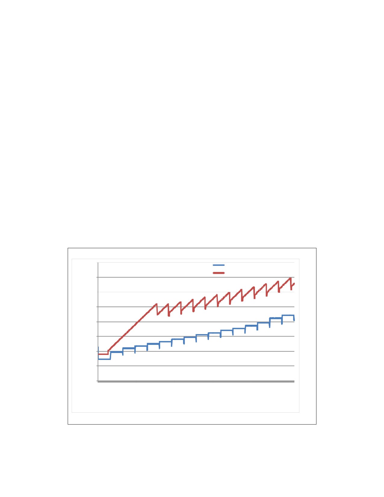
GENERAL OPTIMIZATION GUIDELINES
3.7.6
Enhanced REP MOVSB and STOSB Operation
Beginning with processors based on Ivy Bridge microarchitecture, REP string operation using MOVSB and
STOSB can provide both flexible and high-performance REP string operations for software in common
situations like memory copy and set operations. Processors that provide enhanced MOVSB/STOSB oper-
ations are enumerated by the CPUID feature flag: CPUID:(EAX=7H, ECX=0H):EBX.[bit 9] = 1.
3.7.6.1
Fast Short REP MOVSB
Beginning with processors based on Ice Lake Client microarchitecture, REP MOVSB performance of short
operations is enhanced. The enhancement applies to string lengths between 1 and 128 bytes long.
Support for fast-short REP MOVSB is enumerated by the CPUID feature flag: CPUID [EAX=7H,
ECX=0H).EDX.FAST_SHORT_REP_MOVSB[bit 4] = 1. There is no change in the REP STOS performance.
3.7.6.2
Memcpy Considerations
The interface for the standard library function memcpy introduces several factors (e.g. length, alignment
of the source buffer and destination) that interact with microarchitecture to determine the performance
characteristics of the implementation of the library function. Two of the common approaches to imple-
ment memcpy are driven from small code size vs. maximum throughput. The former generally uses REP
MOVSD+B (see Section 3.7.5), while the latter uses SIMD instruction sets and has to deal with additional
data alignment restrictions.
For processors supporting enhanced REP MOVSB/STOSB, implementing memcpy with REP MOVSB will
provide even more compact benefits in code size and better throughput than using the combination of
REP MOVSD+B. For processors based on Ivy Bridge microarchitecture, implementing memcpy using
Enhanced REP MOVSB and STOSB might not reach the same level of throughput as using 256-bit or
128-bit AVX alternatives, depending on length and alignment factors.
160
REP MOVSB
REP MOVSD+B
140
120
100
s80
e
c
y
60
c
40
20
0
0
2
4
6
8
0
2
4
6
8
0
2
4
6
8
0
2
4
6
8
0
2
4
6
8
0
2
4
6
8
0
2
4
3
6
9
2
6
9
2
5
8
2
5
8
1
4
8
1
4
7
0
4
7
0
3
6
0
3
6
9
2
6
9
2
1
1
1
2
2
2
3
3
3
4
4
4
5
5
5
6
6
6
7
7
7
8
8
8
8
9
9
9
0
1
length in bytes
Figure 3-3. Memcpy Performance Comparison for Lengths up to 2KB
Ref#: 248966-048
3-61

GENERAL OPTIMIZATION GUIDELINES
Figure 3-3 depicts the relative performance of memcpy implementation on a third-generation Intel Core
processor using Enhanced REP MOVSB and STOSB versus REP MOVSD+B, for alignment conditions when
both the source and destination addresses are aligned to a 16-Byte boundary and the source region does
not overlap with the destination region. Using Enhanced REP MOVSB and STOSB always delivers better
performance than using REP MOVSD+B. If the length is a multiple of 64, it can produce even higher
performance. For example, copying 65-128 bytes takes 40 cycles, while copying 128 bytes needs only 35
cycles.
If an application wishes to bypass standard memcpy library implementation with its own custom imple-
mentation and have freedom to manage the buffer length allocation for both source and destination, it
may be worthwhile to manipulate the lengths of its memory copy operation to be multiples of 64 to take
advantage the code size and performance benefit of Enhanced REP MOVSB and STOSB.
The performance characteristic of implementing a general-purpose memcpy library function using a
SIMD register is significantly more colorful than an equivalent implementation using a general-purpose
register, depending on length, instruction set selection between SSE2, 128-bit AVX, 256-bit AVX, relative
alignment of source/destination, and memory address alignment granularities/boundaries, etc.
Hence comparing performance characteristics between a memcpy using Enhanced REP MOVSB and
STOSB versus a SIMD implementation is highly dependent on the particular SIMD implementation. The
remainder of this section discusses the relative performance of memcpy using Enhanced REP MOVSB and
STOSB versus unpublished, optimized 128-bit AVX implementation of memcpy to illustrate the hardware
capability of Ivy Bridge microarchitecture.
Table 3-5. Relative Performance of Memcpy() Using Enhanced REP MOVSB and STOSB Vs. 128-bit AVX
Range of Lengths (bytes)
<128
128 to 2048
2048 to 4096
Memcpy_ERMSB/Memcpy_AVX128
0x7X
1X
1.02X
Table 3-5 shows the relative performance of the Memcpy function implemented using enhanced REP
MOVSB versus 128-bit AVX for several ranges of memcpy lengths, when both the source and destination
addresses are 16-byte aligned and the source region and destination region do not overlap. For memcpy
length less than 128 bytes, using Enhanced REP MOVSB and STOSB is slower than what’s possible using
128-bit AVX, due to internal start-up overhead in the REP string.
For situations with address misalignment, memcpy performance will generally be reduced relative to the
16-byte alignment scenario (see Table 3-6).
Table 3-6. Effect of Address Misalignment on Memcpy() Performance
Address Misalignment
Performance Impact
Source Buffer
The impact on Enhanced REP MOVSB and STOSB implementation versus
128-bit AVX is similar.
Destination Buffer
The impact on Enhanced REP MOVSB and STOSB implementation can be 25%
degradation, while 128-bit AVX implementation of memcpy may degrade only
5%, relative to 16-byte aligned scenario.
Memcpy() implemented with Enhanced REP MOVSB and STOSB can benefit further from the 256-bit
SIMD integer data-path in Haswell microarchitecture. See Section 15.16.3.
3.7.6.3
Memmove Considerations
When there is an overlap between the source and destination regions, software may need to use
memmove instead of memcpy to ensure correctness. It is possible to use REP MOVSB in conjunction with
the direction flag (DF) in a memmove() implementation to handle situations where the latter part of the
source region overlaps with the beginning of the destination region. However, setting the DF to force REP
MOVSB to copy bytes from high towards low addresses will experience significant performance degrada-
tion.
When using Enhanced REP MOVSB and STOSB to implement memmove function, one can detect the
above situation and handle first the rear chunks in the source region that will be written to as part of the
Ref#: 248966-048
3-62
GENERAL OPTIMIZATION GUIDELINES
destination region, using REP MOVSB with the DF=0, to the non-overlapping region of the destination.
After the overlapping chunks in the rear section are copied, the rest of the source region can be
processed normally, also with DF=0.
3.7.6.4
Memset Considerations
The consideration of code size and throughput also applies for memset() implementations. For proces-
sors supporting Enhanced REP MOVSB and STOSB, using REP STOSB will again deliver more compact
code size and significantly better performance than the combination of STOSD+B technique described in
Section 3.7.5.
When the destination buffer is 16-byte aligned, memset() using Enhanced REP MOVSB and STOSB can
perform better than SIMD approaches. When the destination buffer is misaligned, memset() perfor-
mance using Enhanced REP MOVSB and STOSB can degrade about 20% relative to aligned case, for
processors based on Ivy Bridge microarchitecture. In contrast, SIMD implementation of memset() will
experience smaller degradation when the destination is misaligned.
Memset() implemented with Enhanced REP MOVSB and STOSB can benefit further from the 256-bit data
path in Haswell microarchitecture. see Section 15.16.3.3.
3.8
REP STRING OPERATIONS
Several REP string performance enhancements are available beginning with processors based on Golden
Cove microarchitecture.
3.8.1
Fast Zero Length REP MOVSB
REP MOVSB performance of zero length operations is enhanced. The latency of a zero length REP MOVSB
is now the same as the latency of lengths 1 to 128 bytes. When both Fast Short REP MOVSB and Fast Zero
Length REP MOVSB features are enabled, REP MOVSB performance is flat 9 cycles per operation, for all
strings 0-128 byte long whose source and destination operands reside in the processor first level cache.
Support for fast zero-length REP MOVSB is enumerated by the CPUID feature flag:
CPUID.07H.01H:EAX.FAST_ZERO_LENGTH_REP_MOVSB[bit 10] = 1.
3.8.2
Fast Short REP STOSB
REP STOSB performance of short operations is enhanced. The enhancement applies to string lengths
between 0 and 128 bytes long. When Fast Short REP STOSB feature is enabled, REP STOSB performance
is flat 12 cycles per operation, for all strings 0-128 byte long whose destination operand resides in the
processor first level cache.
Support for fast-short REP STOSB is enumerated by the CPUID feature flag:
CPUID.07H.01H:EAX.FAST_SHORT_REP_STOSB[bit 11] = 1.
3.8.3
Fast Short REP CMPSB and SCASB
REP CMPSB and SCASB performance is enhanced. The enhancement applies to string lengths between 1
and 128 bytes long. When the Fast Short REP CMPSB and SCASB feature is enabled, REP CMPSB and REP
SCASB performance is flat 15 cycles per operation, for all strings 1-128 byte long whose two source oper-
ands reside in the processor first level cache.
Support for fast short REP CMPSB and SCASB is enumerated by the CPUID feature flag:
CPUID.07H.01H:EAX.FAST_SHORT_REP_CMPSB_SCASB[bit 12] = 1.
Ref#: 248966-048
3-63
GENERAL OPTIMIZATION GUIDELINES
3.9
FLOATING-POINT CONSIDERATIONS
When programming floating-point applications, it is best to start with a high-level programming language
such as C, C++, or Fortran. Many compilers perform floating-point scheduling and optimization when it
is possible. However in order to produce optimal code, the compiler may need some assistance.
3.9.1
Guidelines for Optimizing Floating-Point Code
User/Source Coding Rule 9. (M impact, M generality) Enable the compiler’s use of Intel SSE, Intel
SSE2, Intel AVX, Intel AVX2, and possibly more advanced SIMD instruction sets (Intel AVX-512) with
appropriate switches. Favor scalar SIMD code generation to replace x87 code generation.
Follow this procedure to investigate the performance of your floating-point application:
• Understand how the compiler handles floating-point code.
• Look at the assembly dump and see what transforms are already performed on the program.
• Study the loop nests in the application that dominate the execution time.
• Determine why the compiler is not creating the fastest code.
• See if there is a dependence that can be resolved.
• Determine the problem area: bus bandwidth, cache locality, trace cache bandwidth, or instruction
latency. Focus on optimizing the problem area. For example, adding PREFETCH instructions will not
help if the bus is already saturated. If trace cache bandwidth is the problem, added prefetch µops
may degrade performance.
Also, in general, follow the general coding recommendations discussed in this chapter, including:
• Blocking the cache.
• Using prefetch.
• Enabling vectorization.
• Unrolling loops.
User/Source Coding Rule 10. (H impact, ML generality) Make sure your application stays in range
to avoid denormal values, underflows.
Out-of-range numbers cause very high overhead.
When converting floating-point values to 16-bit, 32-bit, or 64-bit integers using truncation, the instruc-
tions CVTTSS2SI and CVTTSD2SI are recommended over instructions that access x87 FPU stack. This
avoids changing the rounding mode.
User/Source Coding Rule 11. (M impact, ML generality) Usually, math libraries take advantage of
the transcendental instructions (for example, FSIN) when evaluating elementary functions. If there is
no critical need to evaluate the transcendental functions using the extended precision of 80 bits,
applications should consider an alternate, software-based approach, such as a look-up-table-based
algorithm using interpolation techniques. It is possible to improve transcendental performance with
these techniques by choosing the desired numeric precision and the size of the look-up table, and by
taking advantage of the parallelism of the Intel SSE and the Intel SSE2 instructions.
3.9.2
Floating-Point Modes and Exceptions
When working with floating-point numbers, high-speed microprocessors frequently must deal with situ-
ations that need special handling in hardware or code.
Ref#: 248966-048
3-64