Intel 64 and IA-32 Architectures. Software Developer’s Manual (Collection, 2023) - page 64

INSTRUCTION FORMAT
2.8.9
Exceptions Type E10 and E10NF
EVEX-encoded scalar instructions that ignore EVEX.L’L vector length encoding, do not cause a SIMD FP exception,
and support memory fault suppression follow exception class E10.
Table 2-58. Type E10 Class Exception Conditions
Exception
Cause of Exception
X
X
If EVEX prefix present.
If CR4.OSXSAVE[bit 18]=0.
If any one of following conditions applies:
• State requirement, Table 2-37 not met.
X
X
• Opcode independent #UD condition in Table 2-38.
• Operand encoding #UD conditions in Table 2-39.
Invalid Opcode, #UD
• Opmask encoding #UD condition of Table 2-40.
• EVEX.b encoding #UD condition of Table 2-41.
X
X
X
X
If preceded by a LOCK prefix (F0H).
X
X
If any REX, F2, F3, or 66 prefixes precede a EVEX prefix.
X
X
X
X
If any corresponding CPUID feature flag is ‘0’.
Device Not Available,
X
X
X
X
If CR0.TS[bit 3]=1.
#NM
X
If fault suppression not set, and an illegal address in the SS segment.
Stack, #SS(0)
If fault suppression not set, and a memory address referencing the SS segment is
X
in a non-canonical form.
If fault suppression not set, and an illegal memory operand effective address in the
X
CS, DS, ES, FS or GS segments.
General Protection,
X
If fault suppression not set, and the memory address is in a non-canonical form.
#GP(0)
If fault suppression not set, and any part of the operand lies outside the effective
X
X
address space from 0 to FFFFH.
Page Fault #PF(fault-
X
X
X
If fault suppression not set, and a page fault.
code)
Alignment Check
For 2, 4, or 8 byte memory access if alignment checking is enabled and an
X
X
X
#AC(0)
unaligned memory access is made while the current privilege level is 3.
Vol. 2A
2-63

INSTRUCTION FORMAT
EVEX-encoded scalar instructions that ignore EVEX.L’L vector length encoding, do not cause a SIMD FP exception,
and do not support memory fault suppression follow exception class E10NF.
Table 2-59. Type E10NF Class Exception Conditions
Exception
Cause of Exception
X
X
If EVEX prefix present.
If CR4.OSXSAVE[bit 18]=0.
If any one of following conditions applies:
• State requirement, Table 2-37 not met.
X
X
• Opcode independent #UD condition in Table 2-38.
• Operand encoding #UD conditions in Table 2-39.
Invalid Opcode, #UD
• Opmask encoding #UD condition of Table 2-40.
• EVEX.b encoding #UD condition of Table 2-41.
X
X
X
X
If preceded by a LOCK prefix (F0H).
X
X
If any REX, F2, F3, or 66 prefixes precede a EVEX prefix.
X
X
X
X
If any corresponding CPUID feature flag is ‘0’.
Device Not Available,
X
X
X
X
If CR0.TS[bit 3]=1.
#NM
X
If fault suppression not set, and an illegal address in the SS segment.
Stack, #SS(0)
If fault suppression not set, and a memory address referencing the SS segment is
X
in a non-canonical form.
If fault suppression not set, and an illegal memory operand effective address in the
X
CS, DS, ES, FS or GS segments.
General Protection,
X
If fault suppression not set, and the memory address is in a non-canonical form.
#GP(0)
If fault suppression not set, and any part of the operand lies outside the effective
X
X
address space from 0 to FFFFH.
Page Fault #PF(fault-
X
X
X
If fault suppression not set, and a page fault.
code)
Alignment Check
For 2, 4, or 8 byte memory access if alignment checking is enabled and an
X
X
X
#AC(0)
unaligned memory access is made while the current privilege level is 3.
2-64
Vol. 2A

INSTRUCTION FORMAT
2.8.10 Exception Type E11 (EVEX-only, Mem Arg, No AC, Floating-point Exceptions)
EVEX-encoded instructions that can cause SIMD FP exception, memory operand support fault suppression but do
not cause #AC follow exception class E11.
Table 2-60. Type E11 Class Exception Conditions
Exception
Cause of Exception
Invalid Opcode, #UD
X
X
If EVEX prefix present.
X
X
If CR4.OSXSAVE[bit 18]=0.
If any one of following conditions applies:
• State requirement, Table 2-37 not met.
• Opcode independent #UD condition in Table 2-38.
• Operand encoding #UD conditions in Table 2-39.
• Opmask encoding #UD condition of Table 2-40.
• EVEX.b encoding #UD condition of Table 2-41.
• Instruction specific EVEX.L'L restriction not met.
X
X
X
X
If preceded by a LOCK prefix (F0H).
X
X
If any REX, F2, F3, or 66 prefixes precede a EVEX prefix.
X
X
X
X
If any corresponding CPUID feature flag is ‘0’.
Device Not Available,
X
X
X
X
If CR0.TS[bit 3]=1.
#NM
Stack, #SS(0)
X
If fault suppression not set, and an illegal address in the SS segment.
X
If fault suppression not set, and a memory address referencing the SS segment is
in a non-canonical form.
General Protection,
X
If fault suppression not set, and an illegal memory operand effective address in the
#GP(0)
CS, DS, ES, FS or GS segments.
X
If fault suppression not set, and the memory address is in a non-canonical form.
X
X
If fault suppression not set, and any part of the operand lies outside the effective
address space from 0 to FFFFH.
Page Fault #PF (fault-
X
X
X
If fault suppression not set, and a page fault.
code)
SIMD Floating-Point
X
X
X
X
If an unmasked SIMD floating-point exception, {sae} not set, and CR4.OSXMMEX-
Exception, #XM
CPT[bit 10] = 1.
Vol. 2A
2-65

INSTRUCTION FORMAT
2.8.11 Exception Type E12 and E12NP (VSIB Mem Arg, No AC, No Floating-point Exceptions)
Table 2-61. Type E12 Class Exception Conditions
Exception
Cause of Exception
Invalid Opcode, #UD
X
X
If EVEX prefix present.
X
X
If CR4.OSXSAVE[bit 18]=0.
If any one of following conditions applies:
• State requirement, Table 2-37 not met.
• Opcode independent #UD condition in Table 2-38.
• Operand encoding #UD conditions in Table 2-39.
• Opmask encoding #UD condition of Table 2-40.
• EVEX.b encoding #UD condition of Table 2-41.
• Instruction specific EVEX.L'L restriction not met.
• If vvvv != 1111b.
X
X
X
X
If preceded by a LOCK prefix (F0H).
X
X
If any REX, F2, F3, or 66 prefixes precede a VEX prefix.
X
X
X
NA
If address size attribute is 16 bit.
X
X
X
X
If ModR/M.mod = ‘11b’.
X
X
X
X
If ModR/M.rm != ‘100b’.
X
X
X
X
If any corresponding CPUID feature flag is ‘0’.
X
X
X
X
If k0 is used (gather or scatter operation).
X
X
X
X
If index = destination register (gather operation).
Device Not Available,
X
X
X
X
If CR0.TS[bit 3]=1.
#NM
Stack, #SS(0)
X
For an illegal address in the SS segment.
X
If a memory address referencing the SS segment is in a non-canonical form.
General Protection,
X
For an illegal memory operand effective address in the CS, DS, ES, FS or GS seg-
#GP(0)
ments.
X
If the memory address is in a non-canonical form.
X
X
If any part of the operand lies outside the effective address space from 0 to
FFFFH.
Page Fault #PF (fault-
X
X
X
For a page fault.
code)
2-66
Vol. 2A

INSTRUCTION FORMAT
EVEX-encoded prefetch instructions that do not cause #PF follow exception class E12NP.
Table 2-62. Type E12NP Class Exception Conditions
Exception
Cause of Exception
Invalid Opcode, #UD
X
X
If EVEX prefix present.
X
X
If CR4.OSXSAVE[bit 18]=0.
If any one of following conditions applies:
• State requirement, Table 2-37 not met.
• Opcode independent #UD condition in Table 2-38.
• Operand encoding #UD conditions in Table 2-39.
• Opmask encoding #UD condition of Table 2-40.
• EVEX.b encoding #UD condition of Table 2-41.
• Instruction specific EVEX.L'L restriction not met.
X
X
X
X
If preceded by a LOCK prefix (F0H).
X
X
If any REX, F2, F3, or 66 prefixes precede a VEX prefix.
X
X
X
NA
If address size attribute is 16 bit.
X
X
X
X
If ModR/M.mod = ‘11b’.
X
X
X
X
If ModR/M.rm != ‘100b’.
X
X
X
X
If any corresponding CPUID feature flag is ‘0’.
X
X
X
X
If k0 is used (gather or scatter operation).
Device Not Available,
X
X
X
X
If CR0.TS[bit 3]=1.
#NM
Vol. 2A
2-67

INSTRUCTION FORMAT
2.9
EXCEPTION CLASSIFICATIONS OF OPMASK INSTRUCTIONS
The exception behavior of VEX-encoded opmask instructions are listed below.
Exception conditions of Opmask instructions that do not address memory are listed as Type K20.
Table 2-63. TYPE K20 Exception Definition (VEX-Encoded OpMask Instructions w/o Memory Arg)
Exception
Cause of Exception
Invalid Opcode, #UD
X
X
X
X
If relevant CPUID feature flag is ‘0’.
X
X
If a VEX prefix is present.
X
X
If CR4.OSXSAVE[bit 18]=0.
If any one of following conditions applies:
• State requirement, Table 2-37 not met.
• Opcode independent #UD condition in Table 2-38.
• Operand encoding #UD conditions in Table 2-39.
X
X
If any REX, F2, F3, or 66 prefixes precede a VEX prefix.
X
X
If ModRM:[7:6] != 11b.
Device Not Available,
X
X
X
X
If CR0.TS[bit 3]=1.
#NM
2-68
Vol. 2A

INSTRUCTION FORMAT
Exception conditions of Opmask instructions that address memory are listed as Type K21.
Table 2-64. TYPE K21 Exception Definition (VEX-Encoded OpMask Instructions Addressing Memory)
Exception
Cause of Exception
Invalid Opcode, #UD
X
X
X
X
If relevant CPUID feature flag is ‘0’.
X
X
If a VEX prefix is present.
X
X
If CR4.OSXSAVE[bit 18]=0.
If any one of following conditions applies:
• State requirement, Table 2-37 not met.
• Opcode independent #UD condition in Table 2-38.
• Operand encoding #UD conditions in Table 2-39.
Device Not Available,
X
X
X
X
If CR0.TS[bit 3]=1.
#NM
X
X
If any REX, F2, F3, or 66 prefixes precede a VEX prefix.
Stack, #SS(0)
X
X
X
For an illegal address in the SS segment.
X
If a memory address referencing the SS segment is in a non-canonical form.
General Protection,
X
For an illegal memory operand effective address in the CS, DS, ES, FS or GS seg-
#GP(0)
ments.
If the DS, ES, FS, or GS register is used to access memory and it contains a null
segment selector.
X
If the memory address is in a non-canonical form.
X
X
If any part of the operand lies outside the effective address space from 0 to
FFFFH.
Page Fault #PF(fault-
X
X
X
For a page fault.
code)
Alignment Check
X
X
X
For 2, 4, or 8 byte memory access if alignment checking is enabled and an
#AC(0)
unaligned memory access is made while the current privilege level is 3.
Vol. 2A
2-69

INSTRUCTION FORMAT
2.10
INTEL® AMX INSTRUCTION EXCEPTION CLASSES
Alignment exceptions: The Intel AMX instructions that access memory will never generate #AC exceptions.
Table 2-65. Intel® AMX Exception Classes
Class
Description
• #UD if preceded by LOCK, 66H, F2H, F3H or REX prefixes.
• #UD if CR4.OSXSAVE ≠ 1.
• #UD if XCR0[18:17] ≠ 0b11.
• #UD if IA32_EFER.LMA ≠ 1 OR CS.L ≠ 1.
• #UD if VVVV ≠ 0b1111.
AMX-E1
• #GP based on palette and configuration checks (see pseudocode).
• #GP if the memory address is in a non-canonical form.
• #SS(0) if the memory address referencing the SS segment is in a non-canonical form.
• #PF if a page fault occurs.
• #UD if preceded by LOCK, 66H, F2H, F3H or REX prefixes.
• #UD if CR4.OSXSAVE ≠ 1.
• #UD if XCR0[18:17] ≠ 0b11.
• #UD if IA32_EFER.LMA ≠ 1 OR CS.L ≠ 1.
AMX-E2
• #UD if VVVV ≠ 0b1111.
• #GP if the memory address is in a non-canonical form.
• #SS(0) if the memory address referencing the SS segment is in a non-canonical form.
• #PF if a page fault occurs.
• #UD if preceded by LOCK, 66H, F2H, F3H or REX prefixes.
• #UD if CR4.OSXSAVE ≠ 1.
• #UD if XCR0[18:17] ≠ 0b11.
• #UD if IA32_EFER.LMA ≠ 1 OR CS.L ≠ 1.
• #UD if VVVV ≠ 0b1111.
• #UD if not using SIB addressing.
• #UD if TILES_CONFIGURED == 0.
• #UD if tsrc or tdest are not valid tiles.
AMX-E3
• #UD if tsrc/tdest are ≥ palette_table[tilecfg.palette_id].max_names.
• #UD if tsrc.colbytes mod 4 ≠ 0 OR tdest.colbytes mod 4 ≠ 0.
• #UD if tilecfg.start_row ≥ tsrc.rows OR tilecfg.start_row ≥ tdest.rows.
• #GP if the memory address is in a non-canonical form.
• #SS(0) if the memory address referencing the SS segment is in a non-canonical form.
• #PF if any memory operand causes a page fault.
• #NM if XFD[18] == 1.
2-70
Vol. 2A

INSTRUCTION FORMAT
Table 2-65. Intel® AMX Exception Classes (Contd.)
Class
Description
• #UD if preceded by LOCK, 66H, F2H, F3H or REX prefixes.
• #UD if CR4.OSXSAVE ≠ 1.
• #UD if XCR0[18:17] ≠ 0b11.
• #UD if IA32_EFER.LMA ≠ 1 OR CS.L ≠ 1.
• #UD if srcdest == src1 OR src1 == src2 OR srcdest == src2.
• #UD if TILES_CONFIGURED == 0.
• #UD if srcdest.colbytes mod 4 ≠ 0.
• #UD if src1.colbytes mod 4 ≠ 0.
• #UD if src2.colbytes mod 4 ≠ 0.
AMX-E4
• #UD if srcdest/src1/src2 are not valid tiles.
• #UD if srcdest/src1/src2 are ≥ palette_table[tilecfg.palette_id].max_names.
• #UD if srcdest.colbytes ≠ src2.colbytes.
• #UD if srcdest.rows ≠ src1.rows.
• #UD if src1.colbytes / 4 ≠ src2.rows.
• #UD if srcdest.colbytes > tmul_maxn.
• #UD if src2.colbytes > tmul_maxn.
• #UD if src1.colbytes/4 > tmul_maxk.
• #UD if src2.rows > tmul_maxk.
• #NM if XFD[18] == 1.
• #UD if preceded by LOCK, 66H, F2H, F3H or REX prefixes.
• #UD if CR4.OSXSAVE ≠ 1.
• #UD if XCR0[18:17] ≠ 0b11.
• #UD if IA32_EFER.LMA ≠ 1 OR CS.L ≠ 1.
AMX-E5
• #UD if VVVV ≠ 0b1111.
• #UD if TILES_CONFIGURED == 0.
• #UD if tdest is not a valid tile.
• #UD if tdest is ≥ palette_table[tilecfg.palette_id].max_names.
• #NM if XFD[18] == 1.
• #UD if preceded by LOCK, 66H, F2H, F3H or REX prefixes.
• #UD if CR4.OSXSAVE ≠ 1.
AMX-E6
• #UD if XCR0[18:17] ≠ 0b11.
• #UD if IA32_EFER.LMA ≠ 1 OR CS.L ≠ 1.
• #UD if VVVV ≠ 0b1111.
Vol. 2A
2-71
INSTRUCTION FORMAT
2-72
Vol. 2A

CHAPTER 3
INSTRUCTION SET REFERENCE, A-L
This chapter describes the instruction set for the Intel 64 and IA-32 architectures (A-L) in IA-32e, protected,
virtual-8086, and real-address modes of operation. The set includes general-purpose, x87 FPU, MMX,
SSE/SSE2/SSE3/SSSE3/SSE4, AESNI/PCLMULQDQ, AVX, and system instructions. See also Chapter 4, “Instruc-
tion Set Reference, M-U,” in the Intel® 64 and IA-32 Architectures Software Developer’s Manual, Volume 2B;
Chapter 5, “Instruction Set Reference, V,” in the Intel® 64 and IA-32 Architectures Software Developer’s Manual,
Volume 2C; and Chapter 6, “Instruction Set Reference, W-Z,” in the Intel® 64 and IA-32 Architectures Software
Developer’s Manual, Volume 2D.
For each instruction, each operand combination is described. A description of the instruction and its operand, an
operational description, a description of the effect of the instructions on flags in the EFLAGS register, and a
summary of exceptions that can be generated are also provided.
3.1
INTERPRETING THE INSTRUCTION REFERENCE PAGES
This section describes the format of information contained in the instruction reference pages in this chapter. It
explains notational conventions and abbreviations used in these sections.
3.1.1
Instruction Format
The following is an example of the format used for each instruction description in this chapter. The heading below
introduces the example. The table below provides an example summary table.
CMC—Complement Carry Flag [this is an example]
Opcode
Instruction
Op/En
64/32-bit
CPUID
Description
Mode
Feature Flag
F5
CMC
ZO
V/V
N/A
Complement carry flag.
Instruction Operand Encoding
Op/En
Operand 1
Operand 2
Operand 3
Operand 4
ZO
N/A
N/A
N/A
N/A
Vol. 2A
3-1

INSTRUCTION SET REFERENCE, A-L
3.1.1.1
Opcode Column in the Instruction Summary Table (Instructions without VEX Prefix)
The “Opcode” column in the table above shows the object code produced for each form of the instruction. When
possible, codes are given as hexadecimal bytes in the same order in which they appear in memory. Definitions of
entries other than hexadecimal bytes are as follows:
•
NP — Indicates the use of 66/F2/F3 prefixes (beyond those already part of the instructions opcode) are not
allowed with the instruction. Such use will either cause an invalid-opcode exception (#UD) or result in the
encoding for a different instruction.
•
NFx — Indicates the use of F2/F3 prefixes (beyond those already part of the instructions opcode) are not
allowed with the instruction. Such use will either cause an invalid-opcode exception (#UD) or result in the
encoding for a different instruction.
•
REX.W — Indicates the use of a REX prefix that affects operand size or instruction semantics. The ordering of
the REX prefix and other optional/mandatory instruction prefixes are discussed Chapter 2. Note that REX
prefixes that promote legacy instructions to 64-bit behavior are not listed explicitly in the opcode column.
•
/digit — A digit between 0 and 7 indicates that the ModR/M byte of the instruction uses only the r/m (register
or memory) operand. The reg field contains the digit that provides an extension to the instruction's opcode.
•
/r — Indicates that the ModR/M byte of the instruction contains a register operand and an r/m operand.
•
cb, cw, cd, cp, co, ct — A 1-byte (cb), 2-byte (cw), 4-byte (cd), 6-byte (cp), 8-byte (co) or 10-byte (ct) value
following the opcode. This value is used to specify a code offset and possibly a new value for the code segment
register.
•
ib, iw, id, io — A 1-byte (ib), 2-byte (iw), 4-byte (id) or 8-byte (io) immediate operand to the instruction that
follows the opcode, ModR/M bytes or scale-indexing bytes. The opcode determines if the operand is a signed
value. All words, doublewords, and quadwords are given with the low-order byte first.
•
+rb, +rw, +rd, +ro — Indicated the lower 3 bits of the opcode byte is used to encode the register operand
without a modR/M byte. The instruction lists the corresponding hexadecimal value of the opcode byte with low
3 bits as 000b. In non-64-bit mode, a register code, from 0 through 7, is added to the hexadecimal value of the
opcode byte. In 64-bit mode, indicates the four bit field of REX.b and opcode[2:0] field encodes the register
operand of the instruction. “+ro” is applicable only in 64-bit mode. See Table 3-1 for the codes.
•
+i — A number used in floating-point instructions when one of the operands is ST(i) from the FPU register stack.
The number i (which can range from 0 to 7) is added to the hexadecimal byte given at the left of the plus sign
to form a single opcode byte.
Table 3-1. Register Codes Associated With +rb, +rw, +rd, +ro
byte register
word register
dword register
quadword register
(64-Bit Mode only)
AL
None
0
AX
None
0
EAX
None
0
RAX
None
0
CL
None
1
CX
None
1
ECX
None
1
RCX
None
1
DL
None
2
DX
None
2
EDX
None
2
RDX
None
2
BL
None
3
BX
None
3
EBX
None
3
RBX
None
3
AH
Not
4
SP
None
4
ESP
None
4
N/A
N/A
N/A
encodab
le (N.E.)
CH
N.E.
5
BP
None
5
EBP
None
5
N/A
N/A
N/A
DH
N.E.
6
SI
None
6
ESI
None
6
N/A
N/A
N/A
BH
N.E.
7
DI
None
7
EDI
None
7
N/A
N/A
N/A
SPL
Yes
4
SP
None
4
ESP
None
4
RSP
None
4
BPL
Yes
5
BP
None
5
EBP
None
5
RBP
None
5
3-2
Vol. 2A

INSTRUCTION SET REFERENCE, A-L
Table 3-1. Register Codes Associated With +rb, +rw, +rd, +ro (Contd.)
byte register
word register
dword register
quadword register
(64-Bit Mode only)
SIL
Yes
6
SI
None
6
ESI
None
6
RSI
None
6
DIL
Yes
7
DI
None
7
EDI
None
7
RDI
None
7
Registers R8 - R15 (see below): Available in 64-Bit Mode Only
R8B
Yes
0
R8W
Yes
0
R8D
Yes
0
R8
Yes
0
R9B
Yes
1
R9W
Yes
1
R9D
Yes
1
R9
Yes
1
R10B
Yes
2
R10W
Yes
2
R10D
Yes
2
R10
Yes
2
R11B
Yes
3
R11W
Yes
3
R11D
Yes
3
R11
Yes
3
R12B
Yes
4
R12W
Yes
4
R12D
Yes
4
R12
Yes
4
R13B
Yes
5
R13W
Yes
5
R13D
Yes
5
R13
Yes
5
R14B
Yes
6
R14W
Yes
6
R14D
Yes
6
R14
Yes
6
R15B
Yes
7
R15W
Yes
7
R15D
Yes
7
R15
Yes
7
3.1.1.2
Opcode Column in the Instruction Summary Table (Instructions with VEX prefix)
In the Instruction Summary Table, the Opcode column presents each instruction encoded using the VEX prefix in
following form (including the modR/M byte if applicable, the immediate byte if applicable):
VEX.[128,256].[66,F2,F3].0F/0F3A/0F38.[W0,W1] opcode [/r] [/ib,/is4]
•
VEX — Indicates the presence of the VEX prefix is required. The VEX prefix can be encoded using the three-
byte form (the first byte is C4H), or using the two-byte form (the first byte is C5H). The two-byte form of VEX
only applies to those instructions that do not require the following fields to be encoded: VEX.mmmmm, VEX.W,
VEX.X, VEX.B. Refer to Section 2.3 for more detail on the VEX prefix.
The encoding of various sub-fields of the VEX prefix is described using the following notations:
— 128,256: VEX.L field can be 0 (denoted by VEX.128 or VEX.LZ) or 1 (denoted by VEX.256). The VEX.L field
can be encoded using either the 2-byte or 3-byte form of the VEX prefix. The presence of the notation
VEX.256 or VEX.128 in the opcode column should be interpreted as follows:
• If VEX.256 is present in the opcode column: The semantics of the instruction must be encoded with
VEX.L = 1. An attempt to encode this instruction with VEX.L= 0 can result in one of two situations: (a)
if VEX.128 version is defined, the processor will behave according to the defined VEX.128 behavior; (b)
an #UD occurs if there is no VEX.128 version defined.
• If VEX.128 is present in the opcode column but there is no VEX.256 version defined for the same
opcode byte: Two situations apply: (a) For VEX-encoded, 128-bit SIMD integer instructions, software
must encode the instruction with VEX.L = 0. The processor will treat the opcode byte encoded with
VEX.L= 1 by causing an #UD exception; (b) For VEX-encoded, 128-bit packed floating-point instruc-
tions, software must encode the instruction with VEX.L = 0. The processor will treat the opcode byte
encoded with VEX.L= 1 by causing an #UD exception (e.g. VMOVLPS).
• If VEX.LIG is present in the opcode column: The VEX.L value is ignored. This generally applies to VEX-
encoded scalar SIMD floating-point instructions. Scalar SIMD floating-point instruction can be distin-
guished from the mnemonic of the instruction. Generally, the last two letters of the instruction
mnemonic would be either “SS“, “SD“, or “SI“ for SIMD floating-point conversion instructions.
• If VEX.LZ is present in the opcode column: The VEX.L must be encoded to be 0B, an #UD occurs if
VEX.L is not zero.
— 66,F2,F3: The presence or absence of these values map to the VEX.pp field encodings. If absent, this
corresponds to VEX.pp=00B. If present, the corresponding VEX.pp value affects the “opcode” byte in the
Vol. 2A
3-3
INSTRUCTION SET REFERENCE, A-L
same way as if a SIMD prefix (66H, F2H or F3H) does to the ensuing opcode byte. Thus a non-zero encoding
of VEX.pp may be considered as an implied 66H/F2H/F3H prefix. The VEX.pp field may be encoded using
either the 2-byte or 3-byte form of the VEX prefix.
—
0F,0F3A,0F38: The presence maps to a valid encoding of the VEX.mmmmm field. Only three encoded
values of VEX.mmmmm are defined as valid, corresponding to the escape byte sequence of 0FH, 0F3AH,
and 0F38H. The effect of a valid VEX.mmmmm encoding on the ensuing opcode byte is same as if the corre-
sponding escape byte sequence on the ensuing opcode byte for non-VEX encoded instructions. Thus a valid
encoding of VEX.mmmmm may be consider as an implies escape byte sequence of either 0FH, 0F3AH or
0F38H. The VEX.mmmmm field must be encoded using the 3-byte form of VEX prefix.
—
0F,0F3A,0F38 and 2-byte/3-byte VEX: The presence of 0F3A and 0F38 in the opcode column implies
that opcode can only be encoded by the three-byte form of VEX. The presence of 0F in the opcode column
does not preclude the opcode to be encoded by the two-byte of VEX if the semantics of the opcode does not
require any subfield of VEX not present in the two-byte form of the VEX prefix.
— W0: VEX.W=0.
— W1: VEX.W=1.
— The presence of W0/W1 in the opcode column applies to two situations: (a) it is treated as an extended
opcode bit, (b) the instruction semantics support an operand size promotion to 64-bit of a general-purpose
register operand or a 32-bit memory operand. The presence of W1 in the opcode column implies the opcode
must be encoded using the 3-byte form of the VEX prefix. The presence of W0 in the opcode column does
not preclude the opcode to be encoded using the C5H form of the VEX prefix, if the semantics of the opcode
does not require other VEX subfields not present in the two-byte form of the VEX prefix. Please see Section
2.3 on the subfield definitions within VEX.
— WIG: can use C5H form (if not requiring VEX.mmmmm) or VEX.W value is ignored in the C4H form of VEX
prefix.
— If WIG is present, the instruction may be encoded using either the two-byte form or the three-byte form of
VEX. When encoding the instruction using the three-byte form of VEX, the value of VEX.W is ignored.
•
opcode — Instruction opcode.
•
/is4 — An 8-bit immediate byte is present containing a source register specifier in either imm8[7:4] (for 64-bit
mode) or imm8[6:4] (for 32-bit mode), and instruction-specific payload in imm8[3:0].
•
In general, the encoding o f VEX.R, VEX.X, VEX.B field are not shown explicitly in the opcode column. The
encoding scheme of VEX.R, VEX.X, VEX.B fields must follow the rules defined in Section 2.3.
EVEX.[128,256,512,LLIG].[66,F2,F3].0F/0F3A/0F38.[W0,W1,WIG] opcode [/r] [ib]
• EVEX — The EVEX prefix is encoded using the four-byte form (the first byte is 62H). Refer to Section 2.7.1 for
more detail on the EVEX prefix.
The encoding of various sub-fields of the EVEX prefix is described using the following notations:
— 128, 256, 512, LLIG: This corresponds to the vector length; three values are allowed by EVEX: 512-bit,
256-bit and 128-bit. Alternatively, vector length is ignored (LIG) for certain instructions; this typically
applies to scalar instructions operating on one data element of a vector register.
— 66,F2,F3: The presence of these value maps to the EVEX.pp field encodings. The corresponding VEX.pp
value affects the “opcode” byte in the same way as if a SIMD prefix (66H, F2H or F3H) does to the ensuing
opcode byte. Thus a non-zero encoding of VEX.pp may be considered as an implied 66H/F2H/F3H prefix.
— 0F,0F3A,0F38: The presence maps to a valid encoding of the EVEX.mmm field. Only three encoded values
of EVEX.mmm are defined as valid, corresponding to the escape byte sequence of 0FH, 0F3AH, and 0F38H.
The effect of a valid EVEX.mmm encoding on the ensuing opcode byte is the same as if the corresponding
escape byte sequence on the ensuing opcode byte for non-EVEX encoded instructions. Thus a valid
encoding of EVEX.mmm may be considered as an implied escape byte sequence of either 0FH, 0F3AH or
0F38H.
— W0: EVEX.W=0.
— W1: EVEX.W=1.
3-4
Vol. 2A
INSTRUCTION SET REFERENCE, A-L
— WIG: EVEX.W bit ignored
• opcode — Instruction opcode.
• In general, the encoding of EVEX.R and R’, EVEX.X and X’, and EVEX.B and B’ fields are not shown explicitly in
the opcode column.
NOTE
Previously, the terms NDS, NDD, and DDS were used in instructions with an EVEX (or VEX) prefix.
These terms indicated that the vvvv field was valid for encoding, and specified register usage.
These terms are no longer necessary and are redundant with the instruction operand encoding
tables provided with each instruction. The instruction operand encoding tables give explicit details
on all operands, indicating where every operand is stored and if they are read or written. If vvvv is
not listed as an operand in the instruction operand encoding table, then EVEX (or VEX) vvvv must
be 0b1111.
3.1.1.3
Instruction Column in the Opcode Summary Table
The “Instruction” column gives the syntax of the instruction statement as it would appear in an ASM386 program.
The following is a list of the symbols used to represent operands in the instruction statements:
•
rel8 — A relative address in the range from 128 bytes before the end of the instruction to 127 bytes after the
end of the instruction.
•
rel16, rel32 — A relative address within the same code segment as the instruction assembled. The rel16
symbol applies to instructions with an operand-size attribute of 16 bits; the rel32 symbol applies to instructions
with an operand-size attribute of 32 bits.
•
ptr16:16, ptr16:32 — A far pointer, typically to a code segment different from that of the instruction. The
notation 16:16 indicates that the value of the pointer has two parts. The value to the left of the colon is a 16-
bit selector or value destined for the code segment register. The value to the right corresponds to the offset
within the destination segment. The ptr16:16 symbol is used when the instruction's operand-size attribute is
16 bits; the ptr16:32 symbol is used when the operand-size attribute is 32 bits.
•
r8 — One of the byte general-purpose registers: AL, CL, DL, BL, AH, CH, DH, BH, BPL, SPL, DIL, and SIL; or
one of the byte registers (R8B - R15B) available when using REX.R and 64-bit mode.
•
r16 — One of the word general-purpose registers: AX, CX, DX, BX, SP, BP, SI, DI; or one of the word registers
(R8-R15) available when using REX.R and 64-bit mode.
•
r32 — One of the doubleword general-purpose registers: EAX, ECX, EDX, EBX, ESP, EBP, ESI, EDI; or one of
the doubleword registers (R8D - R15D) available when using REX.R in 64-bit mode.
•
r64 — One of the quadword general-purpose registers: RAX, RBX, RCX, RDX, RDI, RSI, RBP, RSP, R8-R15.
These are available when using REX.R and 64-bit mode.
•
imm8 — An immediate byte value. The imm8 symbol is a signed number between -128 and +127 inclusive.
For instructions in which imm8 is combined with a word or doubleword operand, the immediate value is sign-
extended to form a word or doubleword. The upper byte of the word is filled with the topmost bit of the
immediate value.
•
imm16 — An immediate word value used for instructions whose operand-size attribute is 16 bits. This is a
number between -32,768 and +32,767 inclusive.
•
imm32 — An immediate doubleword value used for instructions whose operand-size attribute is 32
bits. It allows the use of a number between +2,147,483,647 and -2,147,483,648 inclusive.
•
imm64 — An immediate quadword value used for instructions whose operand-size attribute is 64 bits.
The value allows the use of a number between +9,223,372,036,854,775,807 and -
9,223,372,036,854,775,808 inclusive.
•
r/m8 — A byte operand that is either the contents of a byte general-purpose register (AL, CL, DL, BL, AH, CH,
DH, BH, BPL, SPL, DIL, and SIL) or a byte from memory. Byte registers R8B - R15B are available using REX.R
in 64-bit mode.
•
r/m16 — A word general-purpose register or memory operand used for instructions whose operand-size
attribute is 16 bits. The word general-purpose registers are: AX, CX, DX, BX, SP, BP, SI, DI. The contents of
Vol. 2A
3-5
INSTRUCTION SET REFERENCE, A-L
memory are found at the address provided by the effective address computation. Word registers R8W - R15W
are available using REX.R in 64-bit mode.
•
r/m32 — A doubleword general-purpose register or memory operand used for instructions whose operand-
size attribute is 32 bits. The doubleword general-purpose registers are: EAX, ECX, EDX, EBX, ESP, EBP, ESI,
EDI. The contents of memory are found at the address provided by the effective address computation.
Doubleword registers R8D - R15D are available when using REX.R in 64-bit mode.
•
r/m64 — A quadword general-purpose register or memory operand used for instructions whose operand-size
attribute is 64 bits when using REX.W. Quadword general-purpose registers are: RAX, RBX, RCX, RDX, RDI,
RSI, RBP, RSP, R8-R15; these are available only in 64-bit mode. The contents of memory are found at the
address provided by the effective address computation.
•
reg — A general-purpose register used for instructions when the width of the register does not matter to the
semantics of the operation of the instruction. The register can be r16, r32, or r64.
•
m — A 16-, 32- or 64-bit operand in memory.
•
m8 — A byte operand in memory, usually expressed as a variable or array name, but pointed to by the
DS:(E)SI or ES:(E)DI registers. In 64-bit mode, it is pointed to by the RSI or RDI registers.
•
m16 — A word operand in memory, usually expressed as a variable or array name, but pointed to by the
DS:(E)SI or ES:(E)DI registers. This nomenclature is used only with the string instructions.
•
m32 — A doubleword operand in memory. The contents of memory are found at the address provided by the
effective address computation.
•
m64 — A memory quadword operand in memory.
•
m128 — A memory double quadword operand in memory.
•
m16:16, m16:32 & m16:64 — A memory operand containing a far pointer composed of two numbers. The
number to the left of the colon corresponds to the pointer's segment selector. The number to the right
corresponds to its offset.
•
m16&32, m16&16, m32&32, m16&64 — A memory operand consisting of data item pairs whose sizes are
indicated on the left and the right side of the ampersand. All memory addressing modes are allowed. The
m16&16 and m32&32 operands are used by the BOUND instruction to provide an operand containing an upper
and lower bounds for array indices. The m16&32 operand is used by LIDT and LGDT to provide a word with
which to load the limit field, and a doubleword with which to load the base field of the corresponding GDTR and
IDTR registers. The m16&64 operand is used by LIDT and LGDT in 64-bit mode to provide a word with which to
load the limit field, and a quadword with which to load the base field of the corresponding GDTR and IDTR
registers.
•
m80bcd— A Binary Coded Decimal (BCD) operand in memory, 80 bits.
•
moffs8, moffs16, moffs32, moffs64 — A simple memory variable (memory offset) of type byte, word, or
doubleword used by some variants of the MOV instruction. The actual address is given by a simple offset
relative to the segment base. No ModR/M byte is used in the instruction. The number shown with moffs
indicates its size, which is determined by the address-size attribute of the instruction.
•
Sreg — A segment register. The segment register bit assignments are ES = 0, CS = 1, SS = 2, DS = 3, FS = 4,
and GS = 5.
•
m32fp, m64fp, m80fp — A single precision, double precision, and double extended-precision (respectively)
floating-point operand in memory. These symbols designate floating-point values that are used as operands for
x87 FPU floating-point instructions.
•
m16int, m32int, m64int — A word, doubleword, and quadword integer (respectively) operand in memory.
These symbols designate integers that are used as operands for x87 FPU integer instructions.
•
ST or ST(0) — The top element of the FPU register stack.
•
ST(i) — The ith element from the top of the FPU register stack (i := 0 through 7).
•
mm — An MMX register. The 64-bit MMX registers are: MM0 through MM7.
•
mm/m32 — The low order 32 bits of an MMX register or a 32-bit memory operand. The 64-bit MMX registers
are: MM0 through MM7. The contents of memory are found at the address provided by the effective address
computation.
3-6
Vol. 2A
INSTRUCTION SET REFERENCE, A-L
•
mm/m64 — An MMX register or a 64-bit memory operand. The 64-bit MMX registers are: MM0 through MM7.
The contents of memory are found at the address provided by the effective address computation.
•
xmm — An XMM register. The 128-bit XMM registers are: XMM0 through XMM7; XMM8 through XMM15 are
available using REX.R in 64-bit mode.
•
xmm/m32— An XMM register or a 32-bit memory operand. The 128-bit XMM registers are XMM0 through
XMM7; XMM8 through XMM15 are available using REX.R in 64-bit mode. The contents of memory are found at
the address provided by the effective address computation.
•
xmm/m64 — An XMM register or a 64-bit memory operand. The 128-bit SIMD floating-point registers are
XMM0 through XMM7; XMM8 through XMM15 are available using REX.R in 64-bit mode. The contents of
memory are found at the address provided by the effective address computation.
•
xmm/m128 — An XMM register or a 128-bit memory operand. The 128-bit XMM registers are XMM0 through
XMM7; XMM8 through XMM15 are available using REX.R in 64-bit mode. The contents of memory are found at
the address provided by the effective address computation.
•
<XMM0>— Indicates implied use of the XMM0 register.
When there is ambiguity, xmm1 indicates the first source operand using an XMM register and xmm2 the second
source operand using an XMM register.
Some instructions use the XMM0 register as the third source operand, indicated by <XMM0>. The use of the
third XMM register operand is implicit in the instruction encoding and does not affect the ModR/M encoding.
•
ymm — A YMM register. The 256-bit YMM registers are: YMM0 through YMM7; YMM8 through YMM15 are
available in 64-bit mode.
•
m256 — A 32-byte operand in memory. This nomenclature is used only with AVX instructions.
•
ymm/m256 — A YMM register or 256-bit memory operand.
•
<YMM0>— Indicates use of the YMM0 register as an implicit argument.
•
bnd — A 128-bit bounds register. BND0 through BND3.
•
mib — A memory operand using SIB addressing form, where the index register is not used in address calcu-
lation, Scale is ignored. Only the base and displacement are used in effective address calculation.
•
m512 — A 64-byte operand in memory.
•
zmm/m512 — A ZMM register or 512-bit memory operand.
•
{k1}{z} — A mask register used as instruction writemask. The 64-bit k registers are: k1 through k7.
Writemask specification is available exclusively via EVEX prefix. The masking can either be done as a merging-
masking, where the old values are preserved for masked out elements or as a zeroing masking. The type of
masking is determined by using the EVEX.z bit.
•
{k1} — Without {z}: a mask register used as instruction writemask for instructions that do not allow zeroing-
masking but support merging-masking. This corresponds to instructions that require the value of the aaa field
to be different than 0 (e.g., gather) and store-type instructions which allow only merging-masking.
•
k1 — A mask register used as a regular operand (either destination or source). The 64-bit k registers are: k0
through k7.
•
mV — A vector memory operand; the operand size is dependent on the instruction.
•
vm32{x,y, z} — A vector array of memory operands specified using VSIB memory addressing. The array of
memory addresses are specified using a common base register, a constant scale factor, and a vector index
register with individual elements of 32-bit index value in an XMM register (vm32x), a YMM register (vm32y) or
a ZMM register (vm32z).
•
vm64{x,y, z} — A vector array of memory operands specified using VSIB memory addressing. The array of
memory addresses are specified using a common base register, a constant scale factor, and a vector index
register with individual elements of 64-bit index value in an XMM register (vm64x), a YMM register (vm64y) or
a ZMM register (vm64z).
•
zmm/m512/m32bcst — An operand that can be a ZMM register, a 512-bit memory location or a 512-bit
vector loaded from a 32-bit memory location.
•
zmm/m512/m64bcst — An operand that can be a ZMM register, a 512-bit memory location or a 512-bit
vector loaded from a 64-bit memory location.
Vol. 2A
3-7
INSTRUCTION SET REFERENCE, A-L
•
<ZMM0> — Indicates use of the ZMM0 register as an implicit argument.
•
{er} — Indicates support for embedded rounding control, which is only applicable to the register-register form
of the instruction. This also implies support for SAE (Suppress All Exceptions).
•
{sae} — Indicates support for SAE (Suppress All Exceptions). This is used for instructions that support SAE,
but do not support embedded rounding control.
• SRC1 — Denotes the first source operand in the instruction syntax of an instruction encoded with the
VEX/EVEX prefix and having two or more source operands.
• SRC2 — Denotes the second source operand in the instruction syntax of an instruction encoded with the
VEX/EVEX prefix and having two or more source operands.
• SRC3 — Denotes the third source operand in the instruction syntax of an instruction encoded with the
VEX/EVEX prefix and having three source operands.
• SRC — The source in a single-source instruction.
• DST — The destination in an instruction. This field is encoded by reg_field.
In the instruction encoding, the MODRM byte is represented several ways depending on the role it plays. The
MODRM byte has 3 fields: 2-bit MODRM.MOD field, a 3-bit MODRM.REG field and a 3-bit MODRM.RM field. When all
bits of the MODRM byte have fixed values for an instruction, the 2-hex nibble value of that byte is presented after
the opcode in the encoding boxes on the instruction description pages. When only some fields of the MODRM byte
must contain fixed values, those values are specified as follows:
• If only the MODRM.MOD must be 0b11, and MODRM.REG and MODRM.RM fields are unrestricted, this is
denoted as 11:rrr:bbb. The rrr correspond to the 3-bits of the MODRM.REG field and the bbb correspond to
the 3-bits of the MODMR.RM field.
• If the MODRM.MOD field is constrained to be a value other than 0b11, i.e., it must be one of 0b00, 0b01, or
0b10, then we use the notation !(11).
• If the MODRM.REG field had a specific required value, e.g., 0b101, that would be denoted as mm:101:bbb.
3.1.1.4
Operand Encoding Column in the Instruction Summary Table
The “operand encoding” column is abbreviated as Op/En in the Instruction Summary table heading. Instruction
operand encoding information is provided for each assembly instruction syntax using a letter to cross reference to
a row entry in the operand encoding definition table that follows the instruction summary table. The operand
encoding table in each instruction reference page lists each instruction operand (according to each instruction
syntax and operand ordering shown in the instruction column) relative to the ModRM byte, VEX.vvvv field or addi-
tional operand encoding placement.
EVEX encoded instructions employ compressed disp8*N encoding of the displacement bytes, where N is defined in
Table 2-34 and Table 2-35, according to tupletypes. The tupletype for an instruction is listed in the operand
encoding definition table where applicable.
NOTES
• The letters in the Op/En column of an instruction apply ONLY to the encoding definition table
immediately following the instruction summary table.
• In the encoding definition table, the letter ‘r’ within a pair of parenthesis denotes the content of
the operand will be read by the processor. The letter ‘w’ within a pair of parenthesis denotes the
content of the operand will be updated by the processor.
3.1.1.5
64/32-bit Mode Column in the Instruction Summary Table
The “64/32-bit Mode” column indicates whether the opcode sequence is supported in (a) 64-bit mode or (b) the
Compatibility mode and other IA-32 modes that apply in conjunction with the CPUID feature flag associated specific
instruction extensions.
The 64-bit mode support is to the left of the ‘slash’ and has the following notation:
• V — Supported.
• I — Not supported.
3-8
Vol. 2A
INSTRUCTION SET REFERENCE, A-L
• N.E. — Indicates an instruction syntax is not encodable in 64-bit mode (it may represent part of a sequence of
valid instructions in other modes).
• N.P. — Indicates the REX prefix does not affect the legacy instruction in 64-bit mode.
• N.I. — Indicates the opcode is treated as a new instruction in 64-bit mode.
• N.S. — Indicates an instruction syntax that requires an address override prefix in 64-bit mode and is not
supported. Using an address override prefix in 64-bit mode may result in model-specific execution behavior.
The Compatibility/Legacy Mode support is to the right of the ‘slash’ and has the following notation:
• V — Supported.
• I — Not supported.
• N.E. — Indicates an Intel 64 instruction mnemonics/syntax that is not encodable; the opcode sequence is not
applicable as an individual instruction in compatibility mode or IA-32 mode. The opcode may represent a valid
sequence of legacy IA-32 instructions.
3.1.1.6
CPUID Support Column in the Instruction Summary Table
The fourth column holds abbreviated CPUID feature flags (e.g., appropriate bit in CPUID.1.ECX, CPUID.1.EDX
for SSE/SSE2/SSE3/SSSE3/SSE4.1/SSE4.2/AESNI/PCLMULQDQ/AVX/RDRAND support) that indicate processor
support for the instruction. If the corresponding flag is ‘0’, the instruction will #UD.
3.1.1.7
Description Column in the Instruction Summary Table
The “Description” column briefly explains forms of the instruction.
3.1.1.8
Description Section
Each instruction is then described by number of information sections. The “Description” section describes the
purpose of the instructions and required operands in more detail.
Summary of terms that may be used in the description section:
• Legacy SSE — Refers to SSE, SSE2, SSE3, SSSE3, SSE4, AESNI, PCLMULQDQ, and any future instruction sets
referencing XMM registers and encoded without a VEX prefix.
• VEX.vvvv — The VEX bit field specifying a source or destination register (in 1’s complement form).
• rm_field — shorthand for the ModR/M r/m field and any REX.B
• reg_field — shorthand for the ModR/M reg field and any REX.R
3.1.1.9
Operation Section
The “Operation” section contains an algorithm description (frequently written in pseudo-code) for the instruction.
Algorithms are composed of the following elements:
• Comments are enclosed within the symbol pairs “(*” and “*)”.
• Compound statements are enclosed in keywords, such as: IF, THEN, ELSE, and FI for an if statement; DO and
OD for a do statement; or CASE... OF for a case statement.
• A register name implies the contents of the register. A register name enclosed in brackets implies the contents
of the location whose address is contained in that register. For example, ES:[DI] indicates the contents of the
location whose ES segment relative address is in register DI. [SI] indicates the contents of the address
contained in register SI relative to the SI register’s default segment (DS) or the overridden segment.
• Parentheses around the “E” in a general-purpose register name, such as (E)SI, indicates that the offset is read
from the SI register if the address-size attribute is 16, from the ESI register if the address-size attribute is 32.
Parentheses around the “R” in a general-purpose register name, (R)SI, in the presence of a 64-bit register
definition such as (R)SI, indicates that the offset is read from the 64-bit RSI register if the address-size
attribute is 64.
Vol. 2A
3-9

INSTRUCTION SET REFERENCE, A-L
• Brackets are used for memory operands where they mean that the contents of the memory location is a
segment-relative offset. For example, [SRC] indicates that the content of the source operand is a segment-
relative offset.
• A := B indicates that the value of B is assigned to A.
• The symbols =, ≠, >, <, ≥, and ≤ are relational operators used to compare two values: meaning equal, not
equal, greater or equal, less or equal, respectively. A relational expression such as A = B is TRUE if the value of
A is equal to B; otherwise it is FALSE.
• The expression “« COUNT” and “» COUNT” indicates that the destination operand should be shifted left or right
by the number of bits indicated by the count operand.
The following identifiers are used in the algorithmic descriptions:
•
OperandSize and AddressSize — The OperandSize identifier represents the operand-size attribute of the
instruction, which is 16, 32 or 64-bits. The AddressSize identifier represents the address-size attribute, which
is 16, 32 or 64-bits. For example, the following pseudo-code indicates that the operand-size attribute depends
on the form of the MOV instruction used.
IF Instruction = MOVW
THEN OperandSize := 16;
ELSE
IF Instruction = MOVD
THEN OperandSize := 32;
ELSE
IF Instruction = MOVQ
THEN OperandSize := 64;
FI;
FI;
FI;
See “Operand-Size and Address-Size Attributes” in Chapter 3 of the Intel® 64 and IA-32 Architectures
Software Developer’s Manual, Volume 1, for guidelines on how these attributes are determined.
•
StackAddrSize — Represents the stack address-size attribute associated with the instruction, which has a
value of 16, 32 or 64-bits. See “Address-Size Attribute for Stack” in Chapter 6, “Procedure Calls, Interrupts, and
Exceptions,” of the Intel® 64 and IA-32 Architectures Software Developer’s Manual, Volume 1.
•
SRC — Represents the source operand.
•
DEST — Represents the destination operand.
•
MAXVL — The maximum vector register width pertaining to the instruction. This is not the vector-length
encoding in the instruction's encoding but is instead determined by the current value of XCR0. For details, refer
to the table below. Note that the value of MAXVL is the largest of the features enabled. Future processors may
define new bits in XCR0 whose setting may imply other values for MAXVL.
MAXVL Definition
XCR0 Component
MAXVL
XCR0.SSE
128
XCR0.AVX
256
XCR0.{ZMM_Hi256, Hi16_ZMM, OPMASK}
512
The following functions are used in the algorithmic descriptions:
• ZeroExtend(value) — Returns a value zero-extended to the operand-size attribute of the instruction. For
example, if the operand-size attribute is 32, zero extending a byte value of -10 converts the byte from F6H to
a doubleword value of 000000F6H. If the value passed to the ZeroExtend function and the operand-size
attribute are the same size, ZeroExtend returns the value unaltered.
• SignExtend(value) — Returns a value sign-extended to the operand-size attribute of the instruction. For
example, if the operand-size attribute is 32, sign extending a byte containing the value -10 converts the byte
3-10
Vol. 2A

INSTRUCTION SET REFERENCE, A-L
from F6H to a doubleword value of FFFFFFF6H. If the value passed to the SignExtend function and the operand-
size attribute are the same size, SignExtend returns the value unaltered.
•
SaturateSignedWordToSignedByte — Converts a signed 16-bit value to a signed 8-bit value. If the signed
16-bit value is less than -128, it is represented by the saturated value -128 (80H); if it is greater than 127, it
is represented by the saturated value 127 (7FH).
•
SaturateSignedDwordToSignedWord — Converts a signed 32-bit value to a signed 16-bit value. If the
signed 32-bit value is less than -32768, it is represented by the saturated value -32768 (8000H); if it is
greater than 32767, it is represented by the saturated value 32767 (7FFFH).
•
SaturateSignedWordToUnsignedByte — Converts a signed 16-bit value to an unsigned 8-bit value. If the
signed 16-bit value is less than zero, it is represented by the saturated value zero (00H); if it is greater than
255, it is represented by the saturated value 255 (FFH).
•
SaturateToSignedByte — Represents the result of an operation as a signed 8-bit value. If the result is less
than -128, it is represented by the saturated value -128 (80H); if it is greater than 127, it is represented by
the saturated value 127 (7FH).
•
SaturateToSignedWord — Represents the result of an operation as a signed 16-bit value. If the result is less
than -32768, it is represented by the saturated value -32768 (8000H); if it is greater than 32767, it is
represented by the saturated value 32767 (7FFFH).
•
SaturateToUnsignedByte — Represents the result of an operation as a signed 8-bit value. If the result is less
than zero it is represented by the saturated value zero (00H); if it is greater than 255, it is represented by the
saturated value 255 (FFH).
•
SaturateToUnsignedWord — Represents the result of an operation as a signed 16-bit value. If the result is
less than zero it is represented by the saturated value zero (00H); if it is greater than 65535, it is represented
by the saturated value 65535 (FFFFH).
•
LowOrderWord(DEST * SRC) — Multiplies a word operand by a word operand and stores the least significant
word of the doubleword result in the destination operand.
•
HighOrderWord(DEST * SRC) — Multiplies a word operand by a word operand and stores the most
significant word of the doubleword result in the destination operand.
•
Push(value) — Pushes a value onto the stack. The number of bytes pushed is determined by the operand-size
attribute of the instruction. See the “Operation” subsection of the “PUSH—Push Word, Doubleword, or
Quadword Onto the Stack” section in Chapter 4 of the Intel® 64 and IA-32 Architectures Software Developer’s
Manual, Volume 2B.
•
Pop() — removes the value from the top of the stack and returns it. The statement EAX := Pop(); assigns to
EAX the 32-bit value from the top of the stack. Pop will return either a word, a doubleword or a quadword
depending on the operand-size attribute. See the “Operation” subsection in the “POP—Pop a Value From the
Stack” section of Chapter 4 of the Intel® 64 and IA-32 Architectures Software Developer’s Manual, Volume 2B.
•
PopRegisterStack — Marks the FPU ST(0) register as empty and increments the FPU register stack pointer
(TOP) by 1.
•
Switch-Tasks — Performs a task switch.
•
Bit(BitBase, BitOffset) — Returns the value of a bit within a bit string. The bit string is a sequence of bits in
memory or a register. Bits are numbered from low-order to high-order within registers and within memory
bytes. If the BitBase is a register, the BitOffset can be in the range 0 to [15, 31, 63] depending on the mode
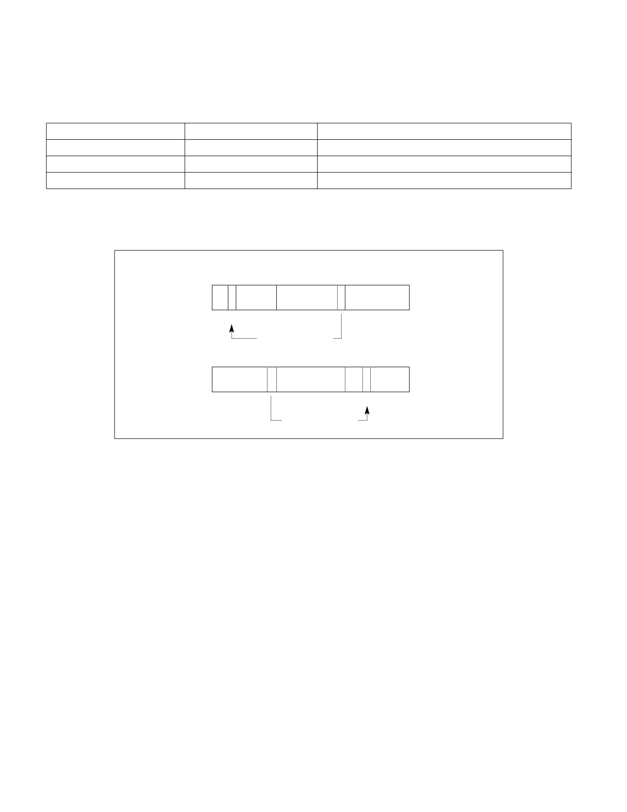
and register size. See Figure 3-1: the function Bit[RAX, 21] is illustrated.
63
31
21
0
Bit Offset := 21
Figure 3-1. Bit Offset for BIT[RAX, 21]
Vol. 2A
3-11
INSTRUCTION SET REFERENCE, A-L
If BitBase is a memory address, the BitOffset has different ranges depending on the operand size (see Table
3-2).
Table 3-2. Range of Bit Positions Specified by Bit Offset Operands
Operand Size
Immediate BitOffset
Register BitOffset
16
0 to 15
− 215 to 215 − 1
32
0 to 31
− 231 to 231 − 1
64
0 to 63
− 263 to 263 − 1
The addressed bit is numbered (Offset MOD 8) within the byte at address (BitBase + (BitOffset DIV 8)) where
DIV is signed division with rounding towards negative infinity and MOD returns a positive number (see
Figure 3-2).
7
5
0 7
0
7
0
BitBase + 1
BitBase
BitBase − 1
BitOffset := +13
7
0 7
0
7
5
0
BitBase
BitBase − 1
BitBase − 2
BitOffset := −11
Figure 3-2. Memory Bit Indexing
3.1.1.10 Intel® C/C++ Compiler Intrinsics Equivalents Section
The Intel C/C++ compiler intrinsic functions give access to the full power of the Intel Architecture Instruction Set,
while allowing the compiler to optimize register allocation and instruction scheduling for faster execution. Most of
these functions are associated with a single IA instruction, although some may generate multiple instructions or
different instructions depending upon how they are used. In particular, these functions are used to invoke instruc-
tions that perform operations on vector registers that can hold multiple data elements. These SIMD instructions
use the following data types.
•
__m128, __m256, and __m512 can represent 4, 8, or 16 packed single precision floating-point values, and are
used with the vector registers and SSE, AVX, or AVX-512 instruction set extension families. The __m128 data
type is also used with various single precision floating-point scalar instructions that perform calculations using
only the lowest 32 bits of a vector register; the remaining bits of the result come from one of the sources or are
set to zero depending upon the instruction.
•
__m128d, __m256d, and __m512d can represent 2, 4, or 8 packed double precision floating-point values, and
are used with the vector registers and SSE, AVX, or AVX-512 instruction set extension families. The __m128d
data type is also used with various double precision floating-point scalar instructions that perform calculations
using only the lowest 64 bits of a vector register; the remaining bits of the result come from one of the sources
or are set to zero depending upon the instruction.
•
__m128i, __m256i, and __m512i can represent integer data in bytes, words, doublewords, quadwords, and
occasionally larger data types.
3-12
Vol. 2A
INSTRUCTION SET REFERENCE, A-L
Each of these data types incorporates in its name the number of bits it can hold. For example, the __m128 type
holds 128 bits, and because each single precision floating-point value is 32 bits long the __m128 type holds
(128/32) or four values. Normally the compiler will allocate memory for these data types on an even multiple of the
size of the type. Such aligned memory locations may be faster to read and write than locations at other addresses.
These SIMD data types are not basic Standard C data types or C++ objects, so they may be used only with the
assignment operator, passed as function arguments, and returned from a function call. If you access the internal
members of these types directly, or indirectly by using them in a union, there may be side effects affecting optimi-
zation, so it is recommended to use them only with the SIMD instruction intrinsic functions described in this manual
or the Intel C/C++ compiler documentation.
Many intrinsic functions names are prefixed with an indicator of the vector length and suffixed by an indicator of
the vector element data type, although some functions do not follow the rules below. The prefixes are:
•
_mm_ indicates that the function operates on 128-bit (or sometimes 64-bit) vectors.
•
_mm256_ indicates the function operates on 256-bit vectors.
•
_mm512_ indicates that the function operates on 512-bit vectors.
The suffixes include:
•
_ps, which indicates a function that operates on packed single precision floating-point data. Packed single
precision floating-point data corresponds to arrays of the C/C++ type float with either 4, 8 or 16 elements.
Values of this type can be loaded from an array using the _mm_loadu_ps, _mm256_loadu_ps, or
_mm512_loadu_ps functions, or created from individual values using _mm_set_ps, _mm256_set_ps, or
_mm512_set_ps functions, and they can be stored in an array using _mm_storeu_ps, _mm256_storeu_ps, or
_mm512_storeu_ps.
•
_ss, which indicates a function that operates on scalar single precision floating-point data. Single precision
floating-point data corresponds to the C/C++ type float, and values of type float can be converted to type
__m128 for use with these functions using the _mm_set_ss function, and converted back using the
_mm_cvtss_f32 function. When used with functions that operate on packed single precision floating-point data
the scalar element corresponds with the first packed value.
•
_pd, which indicates a function that operates on packed double precision floating-point data. Packed double
precision floating-point data corresponds to arrays of the C/C++ type double with either 2, 4, or 8 elements.
Values of this type can be loaded from an array using the _mm_loadu_pd, _mm256_loadu_pd, or
_mm512_loadu_pd functions, or created from individual values using _mm_set_pd, _mm2566_set_pd, or
_mm512_set_pd functions, and they can be stored in an array using _mm_storeu_pd, _mm256_storeu_pd, or
_mm512_storeu_pd.
•
_sd, which indicates a function that operates on scalar double precision floating-point data. Double-precision
floating-point data corresponds to the C/C++ type double, and values of type double can be converted to type
__m128d for use with these functions using the _mm_set_sd function, and converted back using the
_mm_cvtsd_f64 function. When used with functions that operate on packed double precision floating-point
data the scalar element corresponds with the first packed value.
•
_epi8, which indicates a function that operates on packed 8-bit signed integer values. Packed 8-bit signed
integers correspond to an array of signed char with 16, 32 or 64 elements. Values of this type can be created
from individual elements using _mm_set_epi8, _mm256_set_epi8, or _mm512_set_epi8 functions.
•
_epi16, which indicates a function that operates on packed 16-bit signed integer values. Packed 16-bit signed
integers correspond to an array of short with 8, 16 or 32 elements. Values of this type can be created from
individual elements using _mm_set_epi16, _mm256_set_epi16, or _mm512_set_epi16 functions.
•
_epi32, which indicates a function that operates on packed 32-bit signed integer values. Packed 32-bit signed
integers correspond to an array of int with 4, 8 or 16 elements. Values of this type can be created from
individual elements using _mm_set_epi32, _mm256_set_epi32, or _mm512_set_epi32 functions.
•
_epi64, which indicates a function that operates on packed 64-bit signed integer values. Packed 64-bit signed
integers correspond to an array of long long (or long if it is a 64-bit data type) with 2, 4 or 8 elements. Values
of this type can be created from individual elements using _mm_set_epi32, _mm256_set_epi32, or
_mm512_set_epi32 functions.
•
_epu8, which indicates a function that operates on packed 8-bit unsigned integer values. Packed 8-bit unsigned
integers correspond to an array of unsigned char with 16, 32 or 64 elements.
Vol. 2A
3-13

INSTRUCTION SET REFERENCE, A-L
•
_epu16, which indicates a function that operates on packed 16-bit unsigned integer values. Packed 16-bit
unsigned integers correspond to an array of unsigned short with 8, 16 or 32 elements.
•
_epu32, which indicates a function that operates on packed 32-bit unsigned integer values. Packed 32-bit
unsigned integers correspond to an array of unsigned with 4, 8 or 16 elements.
•
_epu64, which indicates a function that operates on packed 64-bit unsigned integer values. Packed 64-bit
unsigned integers correspond to an array of unsigned long long (or unsigned long if it is a 64-bit data type) with
2, 4 or 8 elements.
•
_si128, which indicates a function that operates on a single 128-bit value of type __m128i.
•
_si256, which indicates a function that operates on a single a 256-bit value of type __m256i.
•
_si512, which indicates a function that operates on a single a 512-bit value of type __m512i.
Values of any packed integer type can be loaded from an array using the _mm_loadu_si128,
_mm256_loadu_si256, or _mm512_loadu_si512 functions, and they can be stored in an array using
_mm_storeu_si128, _mm256_storeu_si256, or _mm512_storeu_si512.
These functions and data types are used with the SSE, AVX, and AVX-512 instruction set extension families. In
addition there are similar functions that correspond to MMX instructions. These are less frequently used because
they require additional state management, and only operate on 64-bit packed integer values.
The declarations of Intel C/C++ compiler intrinsic functions may reference some non-standard data types, such as
__int64. The C Standard header stdint.h defines similar platform-independent types, and the documentation for
that header gives characteristics that apply to corresponding non-standard types according to the following table.
Table 3-3. Standard and Non-standard Data Types
Non-standard Type
Standard Type (from stdint.h)
__int64
int64_t
unsigned __int64
uint64_t
__int32
int32_t
unsigned __int32
uint32_t
__int16
int16_t
unsigned __int16
uint16_t
For a more detailed description of each intrinsic function and additional information related to its usage, refer to the
online Intel Intrinsics Guide, https://software.intel.com/sites/landingpage/IntrinsicsGuide.
3.1.1.11 Flags Affected Section
The “Flags Affected” section lists the flags in the EFLAGS register that are affected by the instruction. When a flag
is cleared, it is equal to 0; when it is set, it is equal to 1. The arithmetic and logical instructions usually assign values
to the status flags in a uniform manner (see Appendix A, “EFLAGS Cross-Reference,” in the Intel® 64 and IA-32
Architectures Software Developer’s Manual, Volume 1). Non-conventional assignments are described in the “Oper-
ation” section. The values of flags listed as undefined may be changed by the instruction in an indeterminate
manner. Flags that are not listed are unchanged by the instruction.
3.1.1.12 FPU Flags Affected Section
The floating-point instructions have an “FPU Flags Affected” section that describes how each instruction can affect
the four condition code flags of the FPU status word.
3.1.1.13 Protected Mode Exceptions Section
The “Protected Mode Exceptions” section lists the exceptions that can occur when the instruction is executed in
protected mode and the reasons for the exceptions. Each exception is given a mnemonic that consists of a pound
3-14
Vol. 2A

INSTRUCTION SET REFERENCE, A-L
sign (#) followed by two letters and an optional error code in parentheses. For example, #GP(0) denotes a general
protection exception with an error code of 0. Table 3-4 associates each two-letter mnemonic with the corre-
sponding exception vector and name. See Chapter 6, “Procedure Calls, Interrupts, and Exceptions,” in the Intel®
64 and IA-32 Architectures Software Developer’s Manual, Volume 3A, for a detailed description of the exceptions.
Application programmers should consult the documentation provided with their operating systems to determine
the actions taken when exceptions occur.
Table 3-4. Intel 64 and IA-32 General Exceptions
Vector
Name
Source
Protected
Real
Virtual
Mode1
Address
8086
Mode
Mode
0
#DE—Divide Error
DIV and IDIV instructions.
Yes
Yes
Yes
1
#DB—Debug
Any code or data reference.
Yes
Yes
Yes
3
#BP—Breakpoint
INT3 instruction.
Yes
Yes
Yes
4
#OF—Overflow
INTO instruction.
Yes
Yes
Yes
5
#BR—BOUND Range Exceeded
BOUND instruction.
Yes
Yes
Yes
6
#UD—Invalid Opcode (Undefined
UD instruction or reserved opcode.
Yes
Yes
Yes
Opcode)
7
#NM—Device Not Available (No
Floating-point or WAIT/FWAIT instruction.
Yes
Yes
Yes
Math Coprocessor)
8
#DF—Double Fault
Any instruction that can generate an
Yes
Yes
Yes
exception, an NMI, or an INTR.
10
#TS—Invalid TSS
Task switch or TSS access.
Yes
Reserved
Yes
11
#NP—Segment Not Present
Loading segment registers or accessing system
Yes
Reserved
Yes
segments.
12
#SS—Stack Segment Fault
Stack operations and SS register loads.
Yes
Yes
Yes
13
#GP—General Protection2
Any memory reference and other protection
Yes
Yes
Yes
checks.
14
#PF—Page Fault
Any memory reference.
Yes
Reserved
Yes
16
#MF—Floating-Point Error (Math
Floating-point or WAIT/FWAIT instruction.
Yes
Yes
Yes
Fault)
17
#AC—Alignment Check
Any data reference in memory.
Yes
Reserved
Yes
18
#MC—Machine Check
Model dependent machine check errors.
Yes
Yes
Yes
19
#XM—SIMD Floating-Point
SSE/SSE2/SSE3 floating-point instructions.
Yes
Yes
Yes
Numeric Error
NOTES:
1. Apply to protected mode, compatibility mode, and 64-bit mode.
2. In the real-address mode, vector 13 is the segment overrun exception.
3.1.1.14 Real-Address Mode Exceptions Section
The “Real-Address Mode Exceptions” section lists the exceptions that can occur when the instruction is executed in
real-address mode (see Table 3-4).
3.1.1.15 Virtual-8086 Mode Exceptions Section
The “Virtual-8086 Mode Exceptions” section lists the exceptions that can occur when the instruction is executed in
virtual-8086 mode (see Table 3-4).
Vol. 2A
3-15

INSTRUCTION SET REFERENCE, A-L
3.1.1.16 Floating-Point Exceptions Section
The “Floating-Point Exceptions” section lists exceptions that can occur when an x87 FPU floating-point instruction
is executed. All of these exception conditions result in a floating-point error exception (#MF, exception 16) being
generated. Table 3-5 associates a one- or two-letter mnemonic with the corresponding exception name. See
“Floating-Point Exception Conditions” in Chapter 8 of the Intel® 64 and IA-32 Architectures Software Developer’s Manual,
Volume 1, for a detailed description of these exceptions.
Table 3-5. x87 FPU Floating-Point Exceptions
Mnemonic
Name
Source
Floating-point invalid operation:
#IS
- Stack overflow or underflow
- x87 FPU stack overflow or underflow
#IA
- Invalid arithmetic operation
- Invalid FPU arithmetic operation
#Z
Floating-point divide-by-zero
Divide-by-zero
#D
Floating-point denormal operand
Source operand that is a denormal number
#O
Floating-point numeric overflow
Overflow in result
#U
Floating-point numeric underflow
Underflow in result
#P
Floating-point inexact result (precision)
Inexact result (precision)
3.1.1.17 SIMD Floating-Point Exceptions Section
The “SIMD Floating-Point Exceptions” section lists exceptions that can occur when an SSE/SSE2/SSE3 floating-
point instruction is executed. All of these exception conditions result in a SIMD floating-point error exception (#XM,
exception 19) being generated. Table 3-6 associates a one-letter mnemonic with the corresponding exception
name. For a detailed description of these exceptions, refer to ”SSE and SSE2 Exceptions”, in Chapter 11 of the
Intel® 64 and IA-32 Architectures Software Developer’s Manual, Volume 1.
Table 3-6. SIMD Floating-Point Exceptions
Mnemonic
Name
Source
#I
Floating-point invalid operation
Invalid arithmetic operation or source operand
#Z
Floating-point divide-by-zero
Divide-by-zero
#D
Floating-point denormal operand
Source operand that is a denormal number
#O
Floating-point numeric overflow
Overflow in result
#U
Floating-point numeric underflow
Underflow in result
#P
Floating-point inexact result
Inexact result (precision)
3.1.1.18 Compatibility Mode Exceptions Section
This section lists exceptions that occur within compatibility mode.
3.1.1.19
64-Bit Mode Exceptions Section
This section lists exceptions that occur within 64-bit mode.
3.2
INTEL® AMX CONSIDERATIONS
The following implementation parameters and helper functions are applicable to the Intel® AMX instructions.
3-16
Vol. 2A
INSTRUCTION SET REFERENCE, A-L
3.2.1
Implementation Parameters
The parameters are reported via CPUID leaf 1DH. Index 0 reports all zeros for all fields.
define palette_table[id]:
uint16_t total_tile_bytes
uint16_t bytes_per_tile
uint16_t bytes_per_row
uint16_t max_names
uint16_t max_rows
The tile parameters are set by LDTILECFG or XRSTOR* of TILECFG:
define tile[tid]:
byte rows
word colsb // bytes_per_row
bool valid
3.2.2
Helper Functions
The helper functions used in Intel AMX instructions are defined below.
define write_row_and_zero(treg, r, data, nbytes):
for j in 0 ... nbytes-1:
treg.row[r].byte[j] := data.byte[j]
// zero the rest of the row
for j in nbytes ... palette_table[tilecfg.palette_id].bytes_per_row-1:
treg.row[r].byte[j] := 0
define zero_upper_rows(treg, r):
for i in r ... palette_table[tilecfg.palette_id].max_rows-1:
for j in 0 ... palette_table[tilecfg.palette_id].bytes_per_row-1:
treg.row[i].byte[j] := 0
define zero_tilecfg_start():
tilecfg.start_row := 0
define zero_all_tile_data():
if XCR0[TILEDATA]:
b := CPUID(0xD,TILEDATA).EAX // size of feature
for j in 0 ... b:
TILEDATA.byte[j] := 0
Vol. 2A
3-17
INSTRUCTION SET REFERENCE, A-L
define xcr0_supports_palette(palette_id):
if palette_id == 0:
return 1
elif palette_id == 1:
if XCR0[TILECFG] and XCR0[TILEDATA]:
return 1
return 0
3.3
INSTRUCTIONS (A-L)
The remainder of this chapter provides descriptions of Intel 64 and IA-32 instructions (A-L). See also: Chapter 4,
“Instruction Set Reference, M-U,” in the Intel® 64 and IA-32 Architectures Software Developer’s Manual, Volume
2B; Chapter 5, “Instruction Set Reference, V,” in the Intel® 64 and IA-32 Architectures Software Developer’s
Manual, Volume 2C; and Chapter 6, “Instruction Set Reference, W-Z,” in the Intel® 64 and IA-32 Architectures
Software Developer’s Manual, Volume 2D.
3-18
Vol. 2A

INSTRUCTION SET REFERENCE, A-L
AAA—ASCII Adjust After Addition
Opcode
Instruction
Op/
64-bit
Compat/
Description
En
Mode
Leg Mode
37
AAA
ZO
Invalid
Valid
ASCII adjust AL after addition.
Instruction Operand Encoding
Op/En
Operand 1
Operand 2
Operand 3
Operand 4
ZO
N/A
N/A
N/A
N/A
Description
Adjusts the sum of two unpacked BCD values to create an unpacked BCD result. The AL register is the implied
source and destination operand for this instruction. The AAA instruction is only useful when it follows an ADD
instruction that adds (binary addition) two unpacked BCD values and stores a byte result in the AL register. The
AAA instruction then adjusts the contents of the AL register to contain the correct 1-digit unpacked BCD result.
If the addition produces a decimal carry, the AH register increments by 1, and the CF and AF flags are set. If there
was no decimal carry, the CF and AF flags are cleared and the AH register is unchanged. In either case, bits 4
through 7 of the AL register are set to 0.
This instruction executes as described in compatibility mode and legacy mode. It is not valid in 64-bit mode.
Operation
IF 64-Bit Mode
THEN
#UD;
ELSE
IF ((AL AND 0FH) > 9) or (AF = 1)
THEN
AX := AX + 106H;
AF := 1;
CF := 1;
ELSE
AF := 0;
CF := 0;
FI;
AL := AL AND 0FH;
FI;
Flags Affected
The AF and CF flags are set to 1 if the adjustment results in a decimal carry; otherwise they are set to 0. The OF,
SF, ZF, and PF flags are undefined.
Protected Mode Exceptions
#UD
If the LOCK prefix is used.
Real-Address Mode Exceptions
Same exceptions as protected mode.
Virtual-8086 Mode Exceptions
Same exceptions as protected mode.
AAA—ASCII Adjust After Addition
Vol. 2A
3-19
INSTRUCTION SET REFERENCE, A-L
Compatibility Mode Exceptions
Same exceptions as protected mode.
64-Bit Mode Exceptions
#UD
If in 64-bit mode.
3-20
Vol. 2A
AAA—ASCII Adjust After Addition

INSTRUCTION SET REFERENCE, A-L
AAD—ASCII Adjust AX Before Division
Opcode
Instruction
Op/
64-bit
Compat/
Description
En
Mode
Leg Mode
D5 0A
AAD
ZO
Invalid
Valid
ASCII adjust AX before division.
D5 ib
AAD imm8
ZO
Invalid
Valid
Adjust AX before division to number base
imm8.
Instruction Operand Encoding
Op/En
Operand 1
Operand 2
Operand 3
Operand 4
ZO
N/A
N/A
N/A
N/A
Description
Adjusts two unpacked BCD digits (the least-significant digit in the AL register and the most-significant digit in the
AH register) so that a division operation performed on the result will yield a correct unpacked BCD value. The AAD
instruction is only useful when it precedes a DIV instruction that divides (binary division) the adjusted value in the
AX register by an unpacked BCD value.
The AAD instruction sets the value in the AL register to (AL + (10 * AH)), and then clears the AH register to 00H.
The value in the AX register is then equal to the binary equivalent of the original unpacked two-digit (base 10)
number in registers AH and AL.
The generalized version of this instruction allows adjustment of two unpacked digits of any number base (see the
“Operation” section below), by setting the imm8 byte to the selected number base (for example, 08H for octal, 0AH
for decimal, or 0CH for base 12 numbers). The AAD mnemonic is interpreted by all assemblers to mean adjust
ASCII (base 10) values. To adjust values in another number base, the instruction must be hand coded in machine
code (D5 imm8).
This instruction executes as described in compatibility mode and legacy mode. It is not valid in 64-bit mode.
Operation
IF 64-Bit Mode
THEN
#UD;
ELSE
tempAL := AL;
tempAH := AH;
AL := (tempAL + (tempAH ∗ imm8)) AND FFH;
(* imm8 is set to 0AH for the AAD mnemonic.*)
AH := 0;
FI;
The immediate value (imm8) is taken from the second byte of the instruction.
Flags Affected
The SF, ZF, and PF flags are set according to the resulting binary value in the AL register; the OF, AF, and CF flags
are undefined.
Protected Mode Exceptions
#UD
If the LOCK prefix is used.
Real-Address Mode Exceptions
Same exceptions as protected mode.
AAD—ASCII Adjust AX Before Division
Vol. 2A
3-21
INSTRUCTION SET REFERENCE, A-L
Virtual-8086 Mode Exceptions
Same exceptions as protected mode.
Compatibility Mode Exceptions
Same exceptions as protected mode.
64-Bit Mode Exceptions
#UD
If in 64-bit mode.
3-22
Vol. 2A
AAD—ASCII Adjust AX Before Division

INSTRUCTION SET REFERENCE, A-L
AAM—ASCII Adjust AX After Multiply
Opcode
Instruction
Op/
64-bit
Compat/
Description
En
Mode
Leg Mode
D4 0A
AAM
ZO
Invalid
Valid
ASCII adjust AX after multiply.
D4 ib
AAM imm8
ZO
Invalid
Valid
Adjust AX after multiply to number base
imm8.
Instruction Operand Encoding
Op/En
Operand 1
Operand 2
Operand 3
Operand 4
ZO
N/A
N/A
N/A
N/A
Description
Adjusts the result of the multiplication of two unpacked BCD values to create a pair of unpacked (base 10) BCD
values. The AX register is the implied source and destination operand for this instruction. The AAM instruction is
only useful when it follows an MUL instruction that multiplies (binary multiplication) two unpacked BCD values and
stores a word result in the AX register. The AAM instruction then adjusts the contents of the AX register to contain
the correct 2-digit unpacked (base 10) BCD result.
The generalized version of this instruction allows adjustment of the contents of the AX to create two unpacked
digits of any number base (see the “Operation” section below). Here, the imm8 byte is set to the selected number
base (for example, 08H for octal, 0AH for decimal, or 0CH for base 12 numbers). The AAM mnemonic is interpreted
by all assemblers to mean adjust to ASCII (base 10) values. To adjust to values in another number base, the
instruction must be hand coded in machine code (D4 imm8).
This instruction executes as described in compatibility mode and legacy mode. It is not valid in 64-bit mode.
Operation
IF 64-Bit Mode
THEN
#UD;
ELSE
tempAL := AL;
AH := tempAL / imm8; (* imm8 is set to 0AH for the AAM mnemonic *)
AL := tempAL MOD imm8;
FI;
The immediate value (imm8) is taken from the second byte of the instruction.
Flags Affected
The SF, ZF, and PF flags are set according to the resulting binary value in the AL register. The OF, AF, and CF flags
are undefined.
Protected Mode Exceptions
#DE
If an immediate value of 0 is used.
#UD
If the LOCK prefix is used.
Real-Address Mode Exceptions
Same exceptions as protected mode.
Virtual-8086 Mode Exceptions
Same exceptions as protected mode.
AAM—ASCII Adjust AX After Multiply
Vol. 2A
3-23
INSTRUCTION SET REFERENCE, A-L
Compatibility Mode Exceptions
Same exceptions as protected mode.
64-Bit Mode Exceptions
#UD
If in 64-bit mode.
3-24
Vol. 2A
AAM—ASCII Adjust AX After Multiply

INSTRUCTION SET REFERENCE, A-L
AAS—ASCII Adjust AL After Subtraction
Opcode
Instruction
Op/
64-bit
Compat/
Description
En
Mode
Leg Mode
3F
AAS
ZO
Invalid
Valid
ASCII adjust AL after subtraction.
Instruction Operand Encoding
Op/En
Operand 1
Operand 2
Operand 3
Operand 4
ZO
N/A
N/A
N/A
N/A
Description
Adjusts the result of the subtraction of two unpacked BCD values to create a unpacked BCD result. The AL register
is the implied source and destination operand for this instruction. The AAS instruction is only useful when it follows
a SUB instruction that subtracts (binary subtraction) one unpacked BCD value from another and stores a byte
result in the AL register. The AAA instruction then adjusts the contents of the AL register to contain the correct 1-
digit unpacked BCD result.
If the subtraction produced a decimal carry, the AH register decrements by 1, and the CF and AF flags are set. If no
decimal carry occurred, the CF and AF flags are cleared, and the AH register is unchanged. In either case, the AL
register is left with its top four bits set to 0.
This instruction executes as described in compatibility mode and legacy mode. It is not valid in 64-bit mode.
Operation
IF 64-bit mode
THEN
#UD;
ELSE
IF ((AL AND 0FH) > 9) or (AF = 1)
THEN
AX := AX - 6;
AH := AH - 1;
AF := 1;
CF := 1;
AL := AL AND 0FH;
ELSE
CF := 0;
AF := 0;
AL := AL AND 0FH;
FI;
FI;
Flags Affected
The AF and CF flags are set to 1 if there is a decimal borrow; otherwise, they are cleared to 0. The OF, SF, ZF, and
PF flags are undefined.
Protected Mode Exceptions
#UD
If the LOCK prefix is used.
Real-Address Mode Exceptions
Same exceptions as protected mode.
AAS—ASCII Adjust AL After Subtraction
Vol. 2A
3-25
INSTRUCTION SET REFERENCE, A-L
Virtual-8086 Mode Exceptions
Same exceptions as protected mode.
Compatibility Mode Exceptions
Same exceptions as protected mode.
64-Bit Mode Exceptions
#UD
If in 64-bit mode.
3-26
Vol. 2A
AAS—ASCII Adjust AL After Subtraction

INSTRUCTION SET REFERENCE, A-L
ADC—Add With Carry
Opcode
Instruction
Op/
64-bit
Compat/
Description
En
Mode
Leg Mode
14 ib
ADC AL, imm8
I
Valid
Valid
Add with carry imm8 to AL.
15 iw
ADC AX, imm16
I
Valid
Valid
Add with carry imm16 to AX.
15 id
ADC EAX, imm32
I
Valid
Valid
Add with carry imm32 to EAX.
REX.W + 15 id
ADC RAX, imm32
I
Valid
N.E.
Add with carry imm32 sign extended to 64-
bits to RAX.
80 /2 ib
ADC r/m8, imm8
MI
Valid
Valid
Add with carry imm8 to r/m8.
REX + 80 /2 ib
ADC r/m8*, imm8
MI
Valid
N.E.
Add with carry imm8 to r/m8.
81 /2 iw
ADC r/m16, imm16
MI
Valid
Valid
Add with carry imm16 to r/m16.
81 /2 id
ADC r/m32, imm32
MI
Valid
Valid
Add with CF imm32 to r/m32.
REX.W + 81 /2 id
ADC r/m64, imm32
MI
Valid
N.E.
Add with CF imm32 sign extended to 64-bits
to r/m64.
83 /2 ib
ADC r/m16, imm8
MI
Valid
Valid
Add with CF sign-extended imm8 to r/m16.
83 /2 ib
ADC r/m32, imm8
MI
Valid
Valid
Add with CF sign-extended imm8 into r/m32.
REX.W + 83 /2 ib
ADC r/m64, imm8
MI
Valid
N.E.
Add with CF sign-extended imm8 into r/m64.
10 /r
ADC r/m8, r8
MR
Valid
Valid
Add with carry byte register to r/m8.
REX + 10 /r
ADC r/m8*, r8*
MR
Valid
N.E.
Add with carry byte register to r/m64.
11 /r
ADC r/m16, r16
MR
Valid
Valid
Add with carry r16 to r/m16.
11 /r
ADC r/m32, r32
MR
Valid
Valid
Add with CF r32 to r/m32.
REX.W + 11 /r
ADC r/m64, r64
MR
Valid
N.E.
Add with CF r64 to r/m64.
12 /r
ADC r8, r/m8
RM
Valid
Valid
Add with carry r/m8 to byte register.
REX + 12 /r
ADC r8*, r/m8*
RM
Valid
N.E.
Add with carry r/m64 to byte register.
13 /r
ADC r16, r/m16
RM
Valid
Valid
Add with carry r/m16 to r16.
13 /r
ADC r32, r/m32
RM
Valid
Valid
Add with CF r/m32 to r32.
REX.W + 13 /r
ADC r64, r/m64
RM
Valid
N.E.
Add with CF r/m64 to r64.
NOTES:
*In 64-bit mode, r/m8 can not be encoded to access the following byte registers if a REX prefix is used: AH, BH, CH, DH.
Instruction Operand Encoding
Op/En
Operand 1
Operand 2
Operand 3
Operand 4
RM
ModRM:reg (r, w)
ModRM:r/m (r)
N/A
N/A
MR
ModRM:r/m (r, w)
ModRM:reg (r)
N/A
N/A
MI
ModRM:r/m (r, w)
imm8/16/32
N/A
N/A
I
AL/AX/EAX/RAX
imm8/16/32
N/A
N/A
Description
Adds the destination operand (first operand), the source operand (second operand), and the carry (CF) flag and
stores the result in the destination operand. The destination operand can be a register or a memory location; the
source operand can be an immediate, a register, or a memory location. (However, two memory operands cannot be
used in one instruction.) The state of the CF flag represents a carry from a previous addition. When an immediate
value is used as an operand, it is sign-extended to the length of the destination operand format.
ADC—Add With Carry
Vol. 2A
3-27
INSTRUCTION SET REFERENCE, A-L
The ADC instruction does not distinguish between signed or unsigned operands. Instead, the processor evaluates
the result for both data types and sets the OF and CF flags to indicate a carry in the signed or unsigned result,
respectively. The SF flag indicates the sign of the signed result.
The ADC instruction is usually executed as part of a multibyte or multiword addition in which an ADD instruction is
followed by an ADC instruction.
This instruction can be used with a LOCK prefix to allow the instruction to be executed atomically.
In 64-bit mode, the instruction’s default operation size is 32 bits. Using a REX prefix in the form of REX.R permits
access to additional registers (R8-R15). Using a REX prefix in the form of REX.W promotes operation to 64 bits. See
the summary chart at the beginning of this section for encoding data and limits.
Operation
DEST := DEST + SRC + CF;
Intel C/C++ Compiler Intrinsic Equivalent
ADC:
extern unsigned char _addcarry_u8(unsigned char c_in, unsigned char src1, unsigned char src2, unsigned char *sum_out);
ADC:
extern unsigned char _addcarry_u16(unsigned char c_in, unsigned short src1, unsigned short src2, unsigned short
*sum_out);
ADC:
extern unsigned char _addcarry_u32(unsigned char c_in, unsigned int src1, unsigned char int, unsigned int *sum_out);
ADC:
extern unsigned char _addcarry_u64(unsigned char c_in, unsigned __int64 src1, unsigned __int64 src2, unsigned __int64
*sum_out);
Flags Affected
The OF, SF, ZF, AF, CF, and PF flags are set according to the result.
Protected Mode Exceptions
#GP(0)
If the destination is located in a non-writable segment.
If a memory operand effective address is outside the CS, DS, ES, FS, or GS segment limit.
If the DS, ES, FS, or GS register is used to access memory and it contains a NULL segment
selector.
#SS(0)
If a memory operand effective address is outside the SS segment limit.
#PF(fault-code)
If a page fault occurs.
#AC(0)
If alignment checking is enabled and an unaligned memory reference is made while the
current privilege level is 3.
#UD
If the LOCK prefix is used but the destination is not a memory operand.
Real-Address Mode Exceptions
#GP
If a memory operand effective address is outside the CS, DS, ES, FS, or GS segment limit.
#SS
If a memory operand effective address is outside the SS segment limit.
#UD
If the LOCK prefix is used but the destination is not a memory operand.
Virtual-8086 Mode Exceptions
#GP(0)
If a memory operand effective address is outside the CS, DS, ES, FS, or GS segment limit.
#SS(0)
If a memory operand effective address is outside the SS segment limit.
#PF(fault-code)
If a page fault occurs.
#AC(0)
If alignment checking is enabled and an unaligned memory reference is made.
#UD
If the LOCK prefix is used but the destination is not a memory operand.
3-28
Vol. 2A
ADC—Add With Carry
INSTRUCTION SET REFERENCE, A-L
Compatibility Mode Exceptions
Same exceptions as in protected mode.
64-Bit Mode Exceptions
#SS(0)
If a memory address referencing the SS segment is in a non-canonical form.
#GP(0)
If the memory address is in a non-canonical form.
#PF(fault-code)
If a page fault occurs.
#AC(0)
If alignment checking is enabled and an unaligned memory reference is made while the
current privilege level is 3.
#UD
If the LOCK prefix is used but the destination is not a memory operand.
ADC—Add With Carry
Vol. 2A
3-29

INSTRUCTION SET REFERENCE, A-L
ADCX—Unsigned Integer Addition of Two Operands With Carry Flag
Opcode/
Op/
64/32bit
CPUID
Description
Instruction
En
Mode
Feature
Support
Flag
66 0F 38 F6 /r
RM
V/V
ADX
Unsigned addition of r32 with CF, r/m32 to r32, writes CF.
ADCX r32, r/m32
66 REX.w 0F 38 F6 /r
RM
V/NE
ADX
Unsigned addition of r64 with CF, r/m64 to r64, writes CF.
ADCX r64, r/m64
Instruction Operand Encoding
Op/En
Operand 1
Operand 2
Operand 3
Operand 4
RM
ModRM:reg (r, w)
ModRM:r/m (r)
N/A
N/A
Description
Performs an unsigned addition of the destination operand (first operand), the source operand (second operand)
and the carry-flag (CF) and stores the result in the destination operand. The destination operand is a general-
purpose register, whereas the source operand can be a general-purpose register or memory location. The state of
CF can represent a carry from a previous addition. The instruction sets the CF flag with the carry generated by the
unsigned addition of the operands.
The ADCX instruction is executed in the context of multi-precision addition, where we add a series of operands with
a carry-chain. At the beginning of a chain of additions, we need to make sure the CF is in a desired initial state.
Often, this initial state needs to be 0, which can be achieved with an instruction to zero the CF (e.g. XOR).
This instruction is supported in real mode and virtual-8086 mode. The operand size is always 32 bits if not in 64-bit
mode.
In 64-bit mode, the default operation size is 32 bits. Using a REX Prefix in the form of REX.R permits access to addi-
tional registers (R8-15). Using REX Prefix in the form of REX.W promotes operation to 64 bits.
ADCX executes normally either inside or outside a transaction region.
Note: ADCX defines the OF flag differently than the ADD/ADC instructions as defined in Intel® 64 and IA-32 Archi-
tectures Software Developer’s Manual, Volume 2A.
Operation
IF OperandSize is 64-bit
THEN CF:DEST[63:0] := DEST[63:0] + SRC[63:0] + CF;
ELSE CF:DEST[31:0] := DEST[31:0] + SRC[31:0] + CF;
FI;
Flags Affected
CF is updated based on result. OF, SF, ZF, AF, and PF flags are unmodified.
Intel C/C++ Compiler Intrinsic Equivalent
unsigned char _addcarryx_u32 (unsigned char c_in, unsigned int src1, unsigned int src2, unsigned int *sum_out);
unsigned char _addcarryx_u64 (unsigned char c_in, unsigned __int64 src1, unsigned __int64 src2, unsigned __int64 *sum_out);
SIMD Floating-Point Exceptions
None
3-30
Vol. 2A
ADCX—Unsigned Integer Addition of Two Operands With Carry Flag
INSTRUCTION SET REFERENCE, A-L
Protected Mode Exceptions
#UD
If the LOCK prefix is used.
If CPUID.(EAX=07H, ECX=0H):EBX.ADX[bit 19] = 0.
#SS(0)
For an illegal address in the SS segment.
#GP(0)
For an illegal memory operand effective address in the CS, DS, ES, FS or GS segments.
If the DS, ES, FS, or GS register is used to access memory and it contains a null segment
selector.
#PF(fault-code)
For a page fault.
#AC(0)
If alignment checking is enabled and an unaligned memory reference is made while the
current privilege level is 3.
Real-Address Mode Exceptions
#UD
If the LOCK prefix is used.
If CPUID.(EAX=07H, ECX=0H):EBX.ADX[bit 19] = 0.
#SS(0)
For an illegal address in the SS segment.
#GP(0)
If any part of the operand lies outside the effective address space from 0 to FFFFH.
Virtual-8086 Mode Exceptions
#UD
If the LOCK prefix is used.
If CPUID.(EAX=07H, ECX=0H):EBX.ADX[bit 19] = 0.
#SS(0)
For an illegal address in the SS segment.
#GP(0)
If any part of the operand lies outside the effective address space from 0 to FFFFH.
#PF(fault-code)
For a page fault.
#AC(0)
If alignment checking is enabled and an unaligned memory reference is made while the
current privilege level is 3.
Compatibility Mode Exceptions
Same exceptions as in protected mode.
64-Bit Mode Exceptions
#UD
If the LOCK prefix is used.
If CPUID.(EAX=07H, ECX=0H):EBX.ADX[bit 19] = 0.
#SS(0)
If a memory address referencing the SS segment is in a non-canonical form.
#GP(0)
If the memory address is in a non-canonical form.
#PF(fault-code)
For a page fault.
#AC(0)
If alignment checking is enabled and an unaligned memory reference is made while the
current privilege level is 3.
ADCX—Unsigned Integer Addition of Two Operands With Carry Flag
Vol. 2A
3-31

INSTRUCTION SET REFERENCE, A-L
ADD—Add
Opcode
Instruction
Op/
64-bit
Compat/
Description
En
Mode
Leg Mode
04 ib
ADD AL, imm8
I
Valid
Valid
Add imm8 to AL.
05 iw
ADD AX, imm16
I
Valid
Valid
Add imm16 to AX.
05 id
ADD EAX, imm32
I
Valid
Valid
Add imm32 to EAX.
REX.W + 05 id
ADD RAX, imm32
I
Valid
N.E.
Add imm32 sign-extended to 64-bits to RAX.
80 /0 ib
ADD r/m8, imm8
MI
Valid
Valid
Add imm8 to r/m8.
REX + 80 /0 ib
ADD r/m8*, imm8
MI
Valid
N.E.
Add sign-extended imm8 to r/m8.
81 /0 iw
ADD r/m16, imm16
MI
Valid
Valid
Add imm16 to r/m16.
81 /0 id
ADD r/m32, imm32
MI
Valid
Valid
Add imm32 to r/m32.
REX.W + 81 /0 id
ADD r/m64, imm32
MI
Valid
N.E.
Add imm32 sign-extended to 64-bits to
r/m64.
83 /0 ib
ADD r/m16, imm8
MI
Valid
Valid
Add sign-extended imm8 to r/m16.
83 /0 ib
ADD r/m32, imm8
MI
Valid
Valid
Add sign-extended imm8 to r/m32.
REX.W + 83 /0 ib
ADD r/m64, imm8
MI
Valid
N.E.
Add sign-extended imm8 to r/m64.
00 /r
ADD r/m8, r8
MR
Valid
Valid
Add r8 to r/m8.
REX + 00 /r
ADD r/m8*, r8*
MR
Valid
N.E.
Add r8 to r/m8.
01 /r
ADD r/m16, r16
MR
Valid
Valid
Add r16 to r/m16.
01 /r
ADD r/m32, r32
MR
Valid
Valid
Add r32 to r/m32.
REX.W + 01 /r
ADD r/m64, r64
MR
Valid
N.E.
Add r64 to r/m64.
02 /r
ADD r8, r/m8
RM
Valid
Valid
Add r/m8 to r8.
REX + 02 /r
ADD r8*, r/m8*
RM
Valid
N.E.
Add r/m8 to r8.
03 /r
ADD r16, r/m16
RM
Valid
Valid
Add r/m16 to r16.
03 /r
ADD r32, r/m32
RM
Valid
Valid
Add r/m32 to r32.
REX.W + 03 /r
ADD r64, r/m64
RM
Valid
N.E.
Add r/m64 to r64.
NOTES:
*In 64-bit mode, r/m8 can not be encoded to access the following byte registers if a REX prefix is used: AH, BH, CH, DH.
Instruction Operand Encoding
Op/En
Operand 1
Operand 2
Operand 3
Operand 4
RM
ModRM:reg (r, w)
ModRM:r/m (r)
N/A
N/A
MR
ModRM:r/m (r, w)
ModRM:reg (r)
N/A
N/A
MI
ModRM:r/m (r, w)
imm8/16/32
N/A
N/A
I
AL/AX/EAX/RAX
imm8/16/32
N/A
N/A
Description
Adds the destination operand (first operand) and the source operand (second operand) and then stores the result
in the destination operand. The destination operand can be a register or a memory location; the source operand
can be an immediate, a register, or a memory location. (However, two memory operands cannot be used in one
instruction.) When an immediate value is used as an operand, it is sign-extended to the length of the destination
operand format.
The ADD instruction performs integer addition. It evaluates the result for both signed and unsigned integer oper-
ands and sets the OF and CF flags to indicate a carry (overflow) in the signed or unsigned result, respectively. The
SF flag indicates the sign of the signed result.
3-32
Vol. 2A
ADD—Add
INSTRUCTION SET REFERENCE, A-L
This instruction can be used with a LOCK prefix to allow the instruction to be executed atomically.
In 64-bit mode, the instruction’s default operation size is 32 bits. Using a REX prefix in the form of REX.R permits
access to additional registers (R8-R15). Using a REX prefix in the form of REX.W promotes operation to 64 bits. See
the summary chart at the beginning of this section for encoding data and limits.
Operation
DEST := DEST + SRC;
Flags Affected
The OF, SF, ZF, AF, CF, and PF flags are set according to the result.
Protected Mode Exceptions
#GP(0)
If the destination is located in a non-writable segment.
If a memory operand effective address is outside the CS, DS, ES, FS, or GS segment limit.
If the DS, ES, FS, or GS register is used to access memory and it contains a NULL segment
selector.
#SS(0)
If a memory operand effective address is outside the SS segment limit.
#PF(fault-code)
If a page fault occurs.
#AC(0)
If alignment checking is enabled and an unaligned memory reference is made while the
current privilege level is 3.
#UD
If the LOCK prefix is used but the destination is not a memory operand.
Real-Address Mode Exceptions
#GP
If a memory operand effective address is outside the CS, DS, ES, FS, or GS segment limit.
#SS
If a memory operand effective address is outside the SS segment limit.
#UD
If the LOCK prefix is used but the destination is not a memory operand.
Virtual-8086 Mode Exceptions
#GP(0)
If a memory operand effective address is outside the CS, DS, ES, FS, or GS segment limit.
#SS(0)
If a memory operand effective address is outside the SS segment limit.
#PF(fault-code)
If a page fault occurs.
#AC(0)
If alignment checking is enabled and an unaligned memory reference is made.
#UD
If the LOCK prefix is used but the destination is not a memory operand.
Compatibility Mode Exceptions
Same exceptions as in protected mode.
64-Bit Mode Exceptions
#SS(0)
If a memory address referencing the SS segment is in a non-canonical form.
#GP(0)
If the memory address is in a non-canonical form.
#PF(fault-code)
If a page fault occurs.
#AC(0)
If alignment checking is enabled and an unaligned memory reference is made while the
current privilege level is 3.
#UD
If the LOCK prefix is used but the destination is not a memory operand.
ADD—Add
Vol. 2A
3-33

INSTRUCTION SET REFERENCE, A-L
ADDPD—Add Packed Double Precision Floating-Point Values
Opcode/
Op /
64/32
CPUID
Description
Instruction
En
bit Mode
Feature
Support
Flag
66 0F 58 /r
A
V/V
SSE2
Add packed double precision floating-point values from
ADDPD xmm1, xmm2/m128
xmm2/mem to xmm1 and store result in xmm1.
VEX.128.66.0F.WIG 58 /r
B
V/V
AVX
Add packed double precision floating-point values from
VADDPD xmm1,xmm2,
xmm3/mem to xmm2 and store result in xmm1.
xmm3/m128
VEX.256.66.0F.WIG 58 /r
B
V/V
AVX
Add packed double precision floating-point values from
VADDPD ymm1, ymm2,
ymm3/mem to ymm2 and store result in ymm1.
ymm3/m256
EVEX.128.66.0F.W1 58 /r
C
V/V
AVX512VL
Add packed double precision floating-point values from
VADDPD xmm1 {k1}{z}, xmm2,
AVX512F
xmm3/m128/m64bcst to xmm2 and store result in xmm1
xmm3/m128/m64bcst
with writemask k1.
EVEX.256.66.0F.W1 58 /r
C
V/V
AVX512VL
Add packed double precision floating-point values from
VADDPD ymm1 {k1}{z}, ymm2,
AVX512F
ymm3/m256/m64bcst to ymm2 and store result in ymm1
ymm3/m256/m64bcst
with writemask k1.
EVEX.512.66.0F.W1 58 /r
C
V/V
AVX512F
Add packed double precision floating-point values from
VADDPD zmm1 {k1}{z}, zmm2,
zmm3/m512/m64bcst to zmm2 and store result in zmm1
zmm3/m512/m64bcst{er}
with writemask k1.
Instruction Operand Encoding
Op/En
Tuple Type
Operand 1
Operand 2
Operand 3
Operand 4
A
N/A
ModRM:reg (r, w)
ModRM:r/m (r)
N/A
N/A
B
N/A
ModRM:reg (w)
VEX.vvvv (r)
ModRM:r/m (r)
N/A
C
Full
ModRM:reg (w)
EVEX.vvvv (r)
ModRM:r/m (r)
N/A
Description
Adds two, four or eight packed double precision floating-point values from the first source operand to the second
source operand, and stores the packed double precision floating-point result in the destination operand.
EVEX encoded versions: The first source operand is a ZMM/YMM/XMM register. The second source operand can be
a ZMM/YMM/XMM register, a 512/256/128-bit memory location or a 512/256/128-bit vector broadcasted from a
64-bit memory location. The destination operand is a ZMM/YMM/XMM register conditionally updated with
writemask k1.
VEX.256 encoded version: The first source operand is a YMM register. The second source operand can be a YMM
register or a 256-bit memory location. The destination operand is a YMM register. The upper bits (MAXVL-1:256) of
the corresponding ZMM register destination are zeroed.
VEX.128 encoded version: the first source operand is a XMM register. The second source operand is an XMM
register or 128-bit memory location. The destination operand is an XMM register. The upper bits (MAXVL-1:128) of
the corresponding ZMM register destination are zeroed.
128-bit Legacy SSE version: The second source can be an XMM register or an 128-bit memory location. The desti-
nation is not distinct from the first source XMM register and the upper Bits (MAXVL-1:128) of the corresponding
ZMM register destination are unmodified.
3-34
Vol. 2A
ADDPD—Add Packed Double Precision Floating-Point Values
INSTRUCTION SET REFERENCE, A-L
Operation
VADDPD (EVEX encoded versions) when src2 operand is a vector register
(KL, VL) = (2, 128), (4, 256), (8, 512)
IF (VL = 512) AND (EVEX.b = 1)
THEN
SET_ROUNDING_MODE_FOR_THIS_INSTRUCTION(EVEX.RC);
ELSE
SET_ROUNDING_MODE_FOR_THIS_INSTRUCTION(MXCSR.RC);
FI;
FOR j := 0 TO KL-1
i := j * 64
IF k1[j] OR *no writemask*
THEN DEST[i+63:i] := SRC1[i+63:i] + SRC2[i+63:i]
ELSE
IF *merging-masking*
; merging-masking
THEN *DEST[i+63:i] remains unchanged*
ELSE
; zeroing-masking
DEST[i+63:i] := 0
FI
FI;
ENDFOR
DEST[MAXVL-1:VL] := 0
VADDPD (EVEX encoded versions) when src2 operand is a memory source
(KL, VL) = (2, 128), (4, 256), (8, 512)
FOR j := 0 TO KL-1
i := j * 64
IF k1[j] OR *no writemask*
THEN
IF (EVEX.b = 1)
THEN
DEST[i+63:i] := SRC1[i+63:i] + SRC2[63:0]
ELSE
DEST[i+63:i] := SRC1[i+63:i] + SRC2[i+63:i]
FI;
ELSE
IF *merging-masking*
; merging-masking
THEN *DEST[i+63:i] remains unchanged*
ELSE
; zeroing-masking
DEST[i+63:i] := 0
FI
FI;
ENDFOR
DEST[MAXVL-1:VL] := 0
VADDPD (VEX.256 encoded version)
DEST[63:0] := SRC1[63:0] + SRC2[63:0]
DEST[127:64] := SRC1[127:64] + SRC2[127:64]
DEST[191:128] := SRC1[191:128] + SRC2[191:128]
DEST[255:192] := SRC1[255:192] + SRC2[255:192]
DEST[MAXVL-1:256] := 0
ADDPD—Add Packed Double Precision Floating-Point Values
Vol. 2A
3-35
INSTRUCTION SET REFERENCE, A-L
VADDPD (VEX.128 encoded version)
DEST[63:0] := SRC1[63:0] + SRC2[63:0]
DEST[127:64] := SRC1[127:64] + SRC2[127:64]
DEST[MAXVL-1:128] := 0
ADDPD (128-bit Legacy SSE version)
DEST[63:0] := DEST[63:0] + SRC[63:0]
DEST[127:64] := DEST[127:64] + SRC[127:64]
DEST[MAXVL-1:128] (Unmodified)
Intel C/C++ Compiler Intrinsic Equivalent
VADDPD __m512d _mm512_add_pd (__m512d a, __m512d b);
VADDPD __m512d _mm512_mask_add_pd (__m512d s, __mmask8 k, __m512d a, __m512d b);
VADDPD __m512d _mm512_maskz_add_pd (__mmask8 k, __m512d a, __m512d b);
VADDPD __m256d _mm256_mask_add_pd (__m256d s, __mmask8 k, __m256d a, __m256d b);
VADDPD __m256d _mm256_maskz_add_pd (__mmask8 k, __m256d a, __m256d b);
VADDPD __m128d _mm_mask_add_pd (__m128d s, __mmask8 k, __m128d a, __m128d b);
VADDPD __m128d _mm_maskz_add_pd (__mmask8 k, __m128d a, __m128d b);
VADDPD __m512d _mm512_add_round_pd (__m512d a, __m512d b, int);
VADDPD __m512d _mm512_mask_add_round_pd (__m512d s, __mmask8 k, __m512d a, __m512d b, int);
VADDPD __m512d _mm512_maskz_add_round_pd (__mmask8 k, __m512d a, __m512d b, int);
ADDPD __m256d _mm256_add_pd (__m256d a, __m256d b);
ADDPD __m128d _mm_add_pd (__m128d a, __m128d b);
SIMD Floating-Point Exceptions
Overflow, Underflow, Invalid, Precision, Denormal
Other Exceptions
VEX-encoded instruction, see Table 2-19, “Type 2 Class Exception Conditions”.
EVEX-encoded instruction, see Table 2-46, “Type E2 Class Exception Conditions”.
3-36
Vol. 2A
ADDPD—Add Packed Double Precision Floating-Point Values

INSTRUCTION SET REFERENCE, A-L
ADDPS—Add Packed Single Precision Floating-Point Values
Opcode/
Op /
64/32
CPUID
Description
Instruction
En
bit Mode
Feature
Support
Flag
NP 0F 58 /r
A
V/V
SSE
Add packed single precision floating-point values from
ADDPS xmm1, xmm2/m128
xmm2/m128 to xmm1 and store result in xmm1.
VEX.128.0F.WIG 58 /r
B
V/V
AVX
Add packed single precision floating-point values from
VADDPS xmm1,xmm2, xmm3/m128
xmm3/m128 to xmm2 and store result in xmm1.
VEX.256.0F.WIG 58 /r
B
V/V
AVX
Add packed single precision floating-point values from
VADDPS ymm1, ymm2, ymm3/m256
ymm3/m256 to ymm2 and store result in ymm1.
EVEX.128.0F.W0 58 /r
C
V/V
AVX512VL
Add packed single precision floating-point values from
VADDPS xmm1 {k1}{z}, xmm2,
AVX512F
xmm3/m128/m32bcst to xmm2 and store result in
xmm3/m128/m32bcst
xmm1 with writemask k1.
EVEX.256.0F.W0 58 /r
C
V/V
AVX512VL
Add packed single precision floating-point values from
VADDPS ymm1 {k1}{z}, ymm2,
AVX512F
ymm3/m256/m32bcst to ymm2 and store result in
ymm3/m256/m32bcst
ymm1 with writemask k1.
EVEX.512.0F.W0 58 /r
C
V/V
AVX512F
Add packed single precision floating-point values from
VADDPS zmm1 {k1}{z}, zmm2,
zmm3/m512/m32bcst to zmm2 and store result in
zmm3/m512/m32bcst {er}
zmm1 with writemask k1.
Instruction Operand Encoding
Op/En
Tuple Type
Operand 1
Operand 2
Operand 3
Operand 4
A
N/A
ModRM:reg (r, w)
ModRM:r/m (r)
N/A
N/A
B
N/A
ModRM:reg (w)
VEX.vvvv (r)
ModRM:r/m (r)
N/A
C
Full
ModRM:reg (w)
EVEX.vvvv (r)
ModRM:r/m (r)
N/A
Description
Adds four, eight or sixteen packed single precision floating-point values from the first source operand with the
second source operand, and stores the packed single precision floating-point result in the destination operand.
EVEX encoded versions: The first source operand is a ZMM/YMM/XMM register. The second source operand can be
a ZMM/YMM/XMM register, a 512/256/128-bit memory location or a 512/256/128-bit vector broadcasted from a
32-bit memory location. The destination operand is a ZMM/YMM/XMM register conditionally updated with
writemask k1.
VEX.256 encoded version: The first source operand is a YMM register. The second source operand can be a YMM
register or a 256-bit memory location. The destination operand is a YMM register. The upper bits (MAXVL-1:256) of
the corresponding ZMM register destination are zeroed.
VEX.128 encoded version: the first source operand is a XMM register. The second source operand is an XMM
register or 128-bit memory location. The destination operand is an XMM register. The upper bits (MAXVL-1:128) of
the corresponding ZMM register destination are zeroed.
128-bit Legacy SSE version: The second source can be an XMM register or an 128-bit memory location. The desti-
nation is not distinct from the first source XMM register and the upper Bits (MAXVL-1:128) of the corresponding
ZMM register destination are unmodified.
ADDPS—Add Packed Single Precision Floating-Point Values
Vol. 2A
3-37
INSTRUCTION SET REFERENCE, A-L
Operation
VADDPS (EVEX encoded versions) when src2 operand is a register
(KL, VL) = (4, 128), (8, 256), (16, 512)
IF (VL = 512) AND (EVEX.b = 1)
THEN
SET_ROUNDING_MODE_FOR_THIS_INSTRUCTION(EVEX.RC);
ELSE
SET_ROUNDING_MODE_FOR_THIS_INSTRUCTION(MXCSR.RC);
FI;
FOR j := 0 TO KL-1
i := j * 32
IF k1[j] OR *no writemask*
THEN DEST[i+31:i] := SRC1[i+31:i] + SRC2[i+31:i]
ELSE
IF *merging-masking*
; merging-masking
THEN *DEST[i+31:i] remains unchanged*
ELSE
; zeroing-masking
DEST[i+31:i] := 0
FI
FI;
ENDFOR;
DEST[MAXVL-1:VL] := 0
VADDPS (EVEX encoded versions) when src2 operand is a memory source
(KL, VL) = (4, 128), (8, 256), (16, 512)
FOR j := 0 TO KL-1
i := j * 32
IF k1[j] OR *no writemask*
THEN
IF (EVEX.b = 1)
THEN
DEST[i+31:i] := SRC1[i+31:i] + SRC2[31:0]
ELSE
DEST[i+31:i] := SRC1[i+31:i] + SRC2[i+31:i]
FI;
ELSE
IF *merging-masking*
; merging-masking
THEN *DEST[i+31:i] remains unchanged*
ELSE
; zeroing-masking
DEST[i+31:i] := 0
FI
FI;
ENDFOR;
DEST[MAXVL-1:VL] := 0
3-38
Vol. 2A
ADDPS—Add Packed Single Precision Floating-Point Values
INSTRUCTION SET REFERENCE, A-L
VADDPS (VEX.256 encoded version)
DEST[31:0] := SRC1[31:0] + SRC2[31:0]
DEST[63:32] := SRC1[63:32] + SRC2[63:32]
DEST[95:64] := SRC1[95:64] + SRC2[95:64]
DEST[127:96] := SRC1[127:96] + SRC2[127:96]
DEST[159:128] := SRC1[159:128] + SRC2[159:128]
DEST[191:160]:= SRC1[191:160] + SRC2[191:160]
DEST[223:192] := SRC1[223:192] + SRC2[223:192]
DEST[255:224] := SRC1[255:224] + SRC2[255:224].
DEST[MAXVL-1:256] := 0
VADDPS (VEX.128 encoded version)
DEST[31:0] := SRC1[31:0] + SRC2[31:0]
DEST[63:32] := SRC1[63:32] + SRC2[63:32]
DEST[95:64] := SRC1[95:64] + SRC2[95:64]
DEST[127:96] := SRC1[127:96] + SRC2[127:96]
DEST[MAXVL-1:128] := 0
ADDPS (128-bit Legacy SSE version)
DEST[31:0] := SRC1[31:0] + SRC2[31:0]
DEST[63:32] := SRC1[63:32] + SRC2[63:32]
DEST[95:64] := SRC1[95:64] + SRC2[95:64]
DEST[127:96] := SRC1[127:96] + SRC2[127:96]
DEST[MAXVL-1:128] (Unmodified)
Intel C/C++ Compiler Intrinsic Equivalent
VADDPS __m512 _mm512_add_ps (__m512 a, __m512 b);
VADDPS __m512 _mm512_mask_add_ps (__m512 s, __mmask16 k, __m512 a, __m512 b);
VADDPS __m512 _mm512_maskz_add_ps (__mmask16 k, __m512 a, __m512 b);
VADDPS __m256 _mm256_mask_add_ps (__m256 s, __mmask8 k, __m256 a, __m256 b);
VADDPS __m256 _mm256_maskz_add_ps (__mmask8 k, __m256 a, __m256 b);
VADDPS __m128 _mm_mask_add_ps (__m128d s, __mmask8 k, __m128 a, __m128 b);
VADDPS __m128 _mm_maskz_add_ps (__mmask8 k, __m128 a, __m128 b);
VADDPS __m512 _mm512_add_round_ps (__m512 a, __m512 b, int);
VADDPS __m512 _mm512_mask_add_round_ps (__m512 s, __mmask16 k, __m512 a, __m512 b, int);
VADDPS __m512 _mm512_maskz_add_round_ps (__mmask16 k, __m512 a, __m512 b, int);
ADDPS __m256 _mm256_add_ps (__m256 a, __m256 b);
ADDPS __m128 _mm_add_ps (__m128 a, __m128 b);
SIMD Floating-Point Exceptions
Overflow, Underflow, Invalid, Precision, Denormal
Other Exceptions
VEX-encoded instruction, see Table 2-19, “Type 2 Class Exception Conditions”.
EVEX-encoded instruction, see Table 2-46, “Type E2 Class Exception Conditions”.
ADDPS—Add Packed Single Precision Floating-Point Values
Vol. 2A
3-39

INSTRUCTION SET REFERENCE, A-L
ADDSD—Add Scalar Double Precision Floating-Point Values
Opcode/
Op /
64/32
CPUID
Description
Instruction
En
bit Mode
Feature
Support
Flag
F2 0F 58 /r
A
V/V
SSE2
Add the low double precision floating-point value from
ADDSD xmm1, xmm2/m64
xmm2/mem to xmm1 and store the result in xmm1.
VEX.LIG.F2.0F.WIG 58 /r
B
V/V
AVX
Add the low double precision floating-point value from
VADDSD xmm1, xmm2,
xmm3/mem to xmm2 and store the result in xmm1.
xmm3/m64
EVEX.LLIG.F2.0F.W1 58 /r
C
V/V
AVX512F
Add the low double precision floating-point value from
VADDSD xmm1 {k1}{z},
xmm3/m64 to xmm2 and store the result in xmm1 with
xmm2, xmm3/m64{er}
writemask k1.
Instruction Operand Encoding
Op/En
Tuple Type
Operand 1
Operand 2
Operand 3
Operand 4
A
N/A
ModRM:reg (r, w)
ModRM:r/m (r)
N/A
N/A
B
N/A
ModRM:reg (w)
VEX.vvvv (r)
ModRM:r/m (r)
N/A
C
Tuple1 Scalar
ModRM:reg (w)
EVEX.vvvv (r)
ModRM:r/m (r)
N/A
Description
Adds the low double precision floating-point values from the second source operand and the first source operand
and stores the double precision floating-point result in the destination operand.
The second source operand can be an XMM register or a 64-bit memory location. The first source and destination
operands are XMM registers.
128-bit Legacy SSE version: The first source and destination operands are the same. Bits (MAXVL-1:64) of the
corresponding destination register remain unchanged.
EVEX and VEX.128 encoded version: The first source operand is encoded by EVEX.vvvv/VEX.vvvv. Bits (127:64) of
the XMM register destination are copied from corresponding bits in the first source operand. Bits (MAXVL-1:128) of
the destination register are zeroed.
EVEX version: The low quadword element of the destination is updated according to the writemask.
Software should ensure VADDSD is encoded with VEX.L=0. Encoding VADDSD with VEX.L=1 may encounter unpre-
dictable behavior across different processor generations.
3-40
Vol. 2A
ADDSD—Add Scalar Double Precision Floating-Point Values