Intel 64 and IA-32 Architectures. Software Developer’s Manual (Collection, 2023) - page 62

Intel® 64 and IA-32 Architectures
Software Developer’s Manual
Volume 2 (2A, 2B, 2C & 2D):
Instruction Set Reference, A-Z
NOTE: The Intel 64 and IA-32 Architectures Software Developer's Manual consists of four volumes:
Basic Architecture, Order Number 253665; Instruction Set Reference, A-Z, Order Number 325383;
System Programming Guide, Order Number 325384; Model-Specific Registers, Order Number
335592. Refer to all four volumes when evaluating your design needs.
Order Number: 325383-078US
December 2022
CONTENTS
PAGE
CHAPTER 1
ABOUT THIS MANUAL
1.1
INTEL® 64 AND IA-32 PROCESSORS COVERED IN THIS MANUAL
1-1
1.2
OVERVIEW OF VOLUME 2A, 2B, 2C, AND 2D: INSTRUCTION SET REFERENCE
1-4
1.3
NOTATIONAL CONVENTIONS
1-5
1.3.1
Bit and Byte Order
1-5
1.3.2
Reserved Bits and Software Compatibility
1-6
1.3.3
Instruction Operands
1-6
1.3.4
Hexadecimal and Binary Numbers
1-6
1.3.5
Segmented Addressing
1-7
1.3.6
Exceptions
1-7
1.3.7
A New Syntax for CPUID, CR, and MSR Values
1-7
1.4
RELATED LITERATURE
1-8
CHAPTER 2
INSTRUCTION FORMAT
2.1
INSTRUCTION FORMAT FOR PROTECTED MODE, REAL-ADDRESS MODE, AND VIRTUAL-8086 MODE
2-1
2.1.1
Instruction Prefixes
2-1
2.1.2
Opcodes
2-3
2.1.3
ModR/M and SIB Bytes
2-3
2.1.4
Displacement and Immediate Bytes
2-3
2.1.5
Addressing-Mode Encoding of ModR/M and SIB Bytes
2-4
2.2
IA-32E MODE
2-7
2.2.1
REX Prefixes
2-7
2.2.1.1
Encoding
2-8
2.2.1.2
More on REX Prefix Fields
2-8
2.2.1.3
Displacement
2-11
2.2.1.4
Direct Memory-Offset MOVs
2-11
2.2.1.5
Immediates
2-11
2.2.1.6
RIP-Relative Addressing
2-12
2.2.1.7
Default 64-Bit Operand Size
2-12
2.2.2
Additional Encodings for Control and Debug Registers
2-12
2.3
INTEL® ADVANCED VECTOR EXTENSIONS (INTEL® AVX)
2-13
2.3.1
Instruction Format
2-13
2.3.2
VEX and the LOCK prefix
2-13
2.3.3
VEX and the 66H, F2H, and F3H prefixes
2-13
2.3.4
VEX and the REX prefix
2-13
2.3.5
The VEX Prefix
2-14
2.3.5.1
VEX Byte 0, bits[7:0]
2-15
2.3.5.2
VEX Byte 1, bit [7] - ‘R’
2-15
2.3.5.3
3-byte VEX byte 1, bit[6] - ‘X’
2-16
2.3.5.4
3-byte VEX byte 1, bit[5] - ‘B’
2-16
2.3.5.5
3-byte VEX byte 2, bit[7] - ‘W’
2-16
2.3.5.6
2-byte VEX Byte 1, bits[6:3] and 3-byte VEX Byte 2, bits [6:3]- ‘vvvv’ the Source or Dest Register Specifier
2-16
2.3.6
Instruction Operand Encoding and VEX.vvvv, ModR/M
2-17
2.3.6.1
3-byte VEX byte 1, bits[4:0] - “m-mmmm”
2-18
2.3.6.2
2-byte VEX byte 1, bit[2], and 3-byte VEX byte 2, bit [2]- “L”
2-18
2.3.6.3
2-byte VEX byte 1, bits[1:0], and 3-byte VEX byte 2, bits [1:0]- “pp”
2-19
2.3.7
The Opcode Byte
2-19
2.3.8
The ModR/M, SIB, and Displacement Bytes
2-19
2.3.9
The Third Source Operand (Immediate Byte)
2-19
2.3.10
Intel® AVX Instructions and the Upper 128-bits of YMM registers
2-19
2.3.10.1
Vector Length Transition and Programming Considerations
2-19
2.3.11
Intel® AVX Instruction Length
2-20
2.3.12
Vector SIB (VSIB) Memory Addressing
2-20
Vol. 2A
iii
CONTENTS
PAGE
2.3.12.1
64-bit Mode VSIB Memory Addressing
2-21
2.4
INTEL® ADVANCED MATRIX EXTENSIONS (INTEL® AMX)
2-21
2.5
INTEL® AVX AND INTEL® SSE INSTRUCTION EXCEPTION SPECIFICATION
2-22
2.5.1
Exceptions Type 1 (Aligned Memory Reference)
2-27
2.5.2
Exceptions Type 2 (>=16 Byte Memory Reference, Unaligned)
2-28
2.5.3
Exceptions Type 3 (<16 Byte Memory Argument)
2-29
2.5.4
Exceptions Type 4 (>=16 Byte Mem Arg, No Alignment, No Floating-point Exceptions)
2-30
2.5.5
Exceptions Type 5 (<16 Byte Mem Arg and No FP Exceptions)
2-31
2.5.6
Exceptions Type 6 (VEX-Encoded Instructions without Legacy SSE Analogues)
2-32
2.5.7
Exceptions Type 7 (No FP Exceptions, No Memory Arg)
2-33
2.5.8
Exceptions Type 8 (AVX and No Memory Argument)
2-33
2.5.9
Exceptions Type 11 (VEX-only, Mem Arg, No AC, Floating-point Exceptions)
2-34
2.5.10
Exceptions Type 12 (VEX-only, VSIB Mem Arg, No AC, No Floating-point Exceptions)
2-35
2.6
VEX ENCODING SUPPORT FOR GPR INSTRUCTIONS
2-35
2.6.1
Exceptions Type 13 (VEX-Encoded GPR Instructions)
2-36
2.7
INTEL® AVX-512 ENCODING
2-36
2.7.1
Instruction Format and EVEX
2-37
2.7.2
Register Specifier Encoding and EVEX
2-39
2.7.3
Opmask Register Encoding
2-39
2.7.4
Masking Support in EVEX
2-40
2.7.5
Compressed Displacement (disp8*N) Support in EVEX
2-40
2.7.6
EVEX Encoding of Broadcast/Rounding/SAE Support
2-42
2.7.7
Embedded Broadcast Support in EVEX
2-42
2.7.8
Static Rounding Support in EVEX
2-42
2.7.9
SAE Support in EVEX
2-42
2.7.10
Vector Length Orthogonality
2-42
2.7.11
#UD Equations for EVEX
2-43
2.7.11.1
State Dependent #UD
2-43
2.7.11.2
Opcode Independent #UD
2-43
2.7.11.3
Opcode Dependent #UD
2-44
2.7.12
Device Not Available
2-45
2.7.13
Scalar Instructions
2-45
2.8
EXCEPTION CLASSIFICATIONS OF EVEX-ENCODED INSTRUCTIONS
2-45
2.8.1
Exceptions Type E1 and E1NF of EVEX-Encoded Instructions
2-48
2.8.2
Exceptions Type E2 of EVEX-Encoded Instructions
2-51
2.8.3
Exceptions Type E3 and E3NF of EVEX-Encoded Instructions
2-52
2.8.4
Exceptions Type E4 and E4NF of EVEX-Encoded Instructions
2-54
2.8.5
Exceptions Type E5 and E5NF
2-56
2.8.6
Exceptions Type E6 and E6NF
2-58
2.8.7
Exceptions Type E7NM
2-60
2.8.8
Exceptions Type E9 and E9NF
2-61
2.8.9
Exceptions Type E10 and E10NF
2-63
2.8.10
Exception Type E11 (EVEX-only, Mem Arg, No AC, Floating-point Exceptions)
2-65
2.8.11
Exception Type E12 and E12NP (VSIB Mem Arg, No AC, No Floating-point Exceptions)
2-66
2.9
EXCEPTION CLASSIFICATIONS OF OPMASK INSTRUCTIONS
2-68
2.10
INTEL® AMX INSTRUCTION EXCEPTION CLASSES
2-70
CHAPTER 3
INSTRUCTION SET REFERENCE, A-L
3.1
INTERPRETING THE INSTRUCTION REFERENCE PAGES
3-1
3.1.1
Instruction Format
3-1
3.1.1.1
Opcode Column in the Instruction Summary Table (Instructions without VEX Prefix)
3-2
3.1.1.2
Opcode Column in the Instruction Summary Table (Instructions with VEX prefix)
3-3
3.1.1.3
Instruction Column in the Opcode Summary Table
3-5
3.1.1.4
Operand Encoding Column in the Instruction Summary Table
3-8
3.1.1.5
64/32-bit Mode Column in the Instruction Summary Table
3-8
3.1.1.6
CPUID Support Column in the Instruction Summary Table
3-9
3.1.1.7
Description Column in the Instruction Summary Table
3-9
3.1.1.8
Description Section
3-9
iv Vol. 2A
CONTENTS
PAGE
3.1.1.9
Operation Section
3-9
3.1.1.10
Intel® C/C++ Compiler Intrinsics Equivalents Section
3-12
3.1.1.11
Flags Affected Section
3-14
3.1.1.12
FPU Flags Affected Section
3-14
3.1.1.13
Protected Mode Exceptions Section
3-14
3.1.1.14
Real-Address Mode Exceptions Section
3-15
3.1.1.15
Virtual-8086 Mode Exceptions Section
3-15
3.1.1.16
Floating-Point Exceptions Section
3-16
3.1.1.17
SIMD Floating-Point Exceptions Section
3-16
3.1.1.18
Compatibility Mode Exceptions Section
3-16
3.1.1.19
64-Bit Mode Exceptions Section
3-16
3.2
INTEL® AMX CONSIDERATIONS
3-16
3.2.1
Implementation Parameters
3-17
3.2.2
Helper Functions
3-17
3.3
INSTRUCTIONS (A-L)
3-18
AAA—ASCII Adjust After Addition
3-19
AAD—ASCII Adjust AX Before Division
3-21
AAM—ASCII Adjust AX After Multiply
3-23
AAS—ASCII Adjust AL After Subtraction
3-25
ADC—Add With Carry
3-27
ADCX—Unsigned Integer Addition of Two Operands With Carry Flag
3-30
ADD—Add
3-32
ADDPD—Add Packed Double Precision Floating-Point Values
3-34
ADDPS—Add Packed Single Precision Floating-Point Values
3-37
ADDSD—Add Scalar Double Precision Floating-Point Values
3-40
ADDSS—Add Scalar Single Precision Floating-Point Values
3-42
ADDSUBPD—Packed Double Precision Floating-Point Add/Subtract
3-44
ADDSUBPS—Packed Single Precision Floating-Point Add/Subtract
3-46
ADOX — Unsigned Integer Addition of Two Operands With Overflow Flag
3-49
AESDEC—Perform One Round of an AES Decryption Flow
3-51
AESDEC128KL—Perform Ten Rounds of AES Decryption Flow With Key Locker Using 128-Bit Key
3-53
AESDEC256KL—Perform 14 Rounds of AES Decryption Flow With Key Locker Using 256-Bit Key
3-55
AESDECLAST—Perform Last Round of an AES Decryption Flow
3-57
AESDECWIDE128KL—Perform Ten Rounds of AES Decryption Flow With Key Locker on 8 Blocks Using 128-Bit Key 3-59
AESDECWIDE256KL—Perform 14 Rounds of AES Decryption Flow With Key Locker on 8 Blocks Using 256-Bit Key . 3-61
AESENC—Perform One Round of an AES Encryption Flow
3-63
AESENC128KL—Perform Ten Rounds of AES Encryption Flow With Key Locker Using 128-Bit Key
3-65
AESENC256KL—Perform 14 Rounds of AES Encryption Flow With Key Locker Using 256-Bit Key
3-67
AESENCLAST—Perform Last Round of an AES Encryption Flow
3-69
AESENCWIDE128KL—Perform Ten Rounds of AES Encryption Flow With Key Locker on 8 Blocks Using 128-Bit Key 3-71
AESENCWIDE256KL—Perform 14 Rounds of AES Encryption Flow With Key Locker on 8 Blocks Using 256-Bit Key . 3-73
AESIMC—Perform the AES InvMixColumn Transformation
3-75
AESKEYGENASSIST—AES Round Key Generation Assist
3-76
AND—Logical AND
3-78
ANDN—Logical AND NOT
3-80
ANDPD—Bitwise Logical AND of Packed Double Precision Floating-Point Values
3-81
ANDPS—Bitwise Logical AND of Packed Single Precision Floating-Point Values
3-84
ANDNPD—Bitwise Logical AND NOT of Packed Double Precision Floating-Point Values
3-87
ANDNPS—Bitwise Logical AND NOT of Packed Single Precision Floating-Point Values
3-90
ARPL—Adjust RPL Field of Segment Selector
3-93
BEXTR—Bit Field Extract
3-95
BLENDPD—Blend Packed Double Precision Floating-Point Values
3-96
BLENDPS—Blend Packed Single Precision Floating-Point Values
3-98
BLENDVPD—Variable Blend Packed Double Precision Floating-Point Values
3-100
BLENDVPS—Variable Blend Packed Single Precision Floating-Point Values
3-102
BLSI—Extract Lowest Set Isolated Bit
3-105
BLSMSK—Get Mask Up to Lowest Set Bit
3-106
BLSR—Reset Lowest Set Bit
3-107
BNDCL—Check Lower Bound
3-108
Vol. 2A
v
CONTENTS
PAGE
BNDCU/BNDCN—Check Upper Bound
3-110
BNDLDX—Load Extended Bounds Using Address Translation
3-112
BNDMK—Make Bounds
3-115
BNDMOV—Move Bounds
3-117
BNDSTX—Store Extended Bounds Using Address Translation
3-120
BOUND—Check Array Index Against Bounds
3-123
BSF—Bit Scan Forward
3-125
BSR—Bit Scan Reverse
3-127
BSWAP—Byte Swap
3-129
BT—Bit Test
3-130
BTC—Bit Test and Complement
3-132
BTR—Bit Test and Reset
3-134
BTS—Bit Test and Set
3-136
BZHI—Zero High Bits Starting with Specified Bit Position
3-138
CALL—Call Procedure
3-139
CBW/CWDE/CDQE—Convert Byte to Word/Convert Word to Doubleword/Convert Doubleword to Quadword
3-156
CLAC—Clear AC Flag in EFLAGS Register
3-157
CLC—Clear Carry Flag
3-158
CLD—Clear Direction Flag
3-159
CLDEMOTE—Cache Line Demote
3-160
CLFLUSH—Flush Cache Line
3-162
CLFLUSHOPT—Flush Cache Line Optimized
3-164
CLI—Clear Interrupt Flag
3-166
CLRSSBSY—Clear Busy Flag in a Supervisor Shadow Stack Token
3-168
CLTS—Clear Task-Switched Flag in CR0
3-170
CLUI—Clear User Interrupt Flag
3-171
CLWB—Cache Line Write Back
3-172
CMC—Complement Carry Flag
3-174
CMOVcc—Conditional Move
3-175
CMP—Compare Two Operands
3-179
CMPPD—Compare Packed Double Precision Floating-Point Values
3-181
CMPPS—Compare Packed Single Precision Floating-Point Values
3-188
CMPS/CMPSB/CMPSW/CMPSD/CMPSQ—Compare String Operands
3-195
CMPSD—Compare Scalar Double Precision Floating-Point Value
3-199
CMPSS—Compare Scalar Single Precision Floating-Point Value
3-203
CMPXCHG—Compare and Exchange
3-207
CMPXCHG8B/CMPXCHG16B—Compare and Exchange Bytes
3-209
COMISD—Compare Scalar Ordered Double Precision Floating-Point Values and Set EFLAGS
3-212
COMISS—Compare Scalar Ordered Single Precision Floating-Point Values and Set EFLAGS
3-214
CPUID—CPU Identification
3-216
CRC32—Accumulate CRC32 Value
3-261
CVTDQ2PD—Convert Packed Doubleword Integers to Packed Double Precision Floating-Point Values
3-264
CVTDQ2PS—Convert Packed Doubleword Integers to Packed Single Precision Floating-Point Values
3-268
CVTPD2DQ—Convert Packed Double Precision Floating-Point Values to Packed Doubleword Integers
3-271
CVTPD2PI—Convert Packed Double Precision Floating-Point Values to Packed Dword Integers
3-275
CVTPD2PS—Convert Packed Double Precision Floating-Point Values to Packed Single Precision Floating-Point
Values
3-276
CVTPI2PD—Convert Packed Dword Integers to Packed Double Precision Floating-Point Values
3-280
CVTPI2PS—Convert Packed Dword Integers to Packed Single Precision Floating-Point Values
3-281
CVTPS2DQ—Convert Packed Single Precision Floating-Point Values to Packed Signed Doubleword Integer
Values
3-282
CVTPS2PD—Convert Packed Single Precision Floating-Point Values to Packed Double Precision Floating-Point
Values
3-285
CVTPS2PI—Convert Packed Single Precision Floating-Point Values to Packed Dword Integers
3-288
CVTSD2SI—Convert Scalar Double Precision Floating-Point Value to Doubleword Integer
3-289
CVTSD2SS—Convert Scalar Double Precision Floating-Point Value to Scalar Single Precision Floating-Point Value . .3-291
CVTSI2SD—Convert Doubleword Integer to Scalar Double Precision Floating-Point Value
3-293
CVTSI2SS—Convert Doubleword Integer to Scalar Single Precision Floating-Point Value
3-295
CVTSS2SD—Convert Scalar Single Precision Floating-Point Value to Scalar Double Precision Floating-Point Value . .3-297
vi
Vol. 2A
CONTENTS
PAGE
CVTSS2SI—Convert Scalar Single Precision Floating-Point Value to Doubleword Integer
3-299
CVTTPD2DQ—Convert with Truncation Packed Double Precision Floating-Point Values to Packed Doubleword
Integers
3-301
CVTTPD2PI—Convert With Truncation Packed Double Precision Floating-Point Values to Packed Dword Integers . . 3-305
CVTTPS2DQ—Convert With Truncation Packed Single Precision Floating-Point Values to Packed Signed Doubleword
Integer Values
3-306
CVTTPS2PI—Convert With Truncation Packed Single Precision Floating-Point Values to Packed Dword Integers . . . 3-309
CVTTSD2SI—Convert With Truncation Scalar Double Precision Floating-Point Value to Signed Integer
3-310
CVTTSS2SI—Convert With Truncation Scalar Single Precision Floating-Point Value to Integer
3-312
CWD/CDQ/CQO—Convert Word to Doubleword/Convert Doubleword to Quadword
3-314
DAA—Decimal Adjust AL After Addition
3-315
DAS—Decimal Adjust AL After Subtraction
3-317
DEC—Decrement by 1
3-319
DIV—Unsigned Divide
3-321
DIVPD—Divide Packed Double Precision Floating-Point Values
3-324
DIVPS—Divide Packed Single Precision Floating-Point Values
3-327
DIVSD—Divide Scalar Double Precision Floating-Point Value
3-330
DIVSS—Divide Scalar Single Precision Floating-Point Values
3-332
DPPD—Dot Product of Packed Double Precision Floating-Point Values
3-334
DPPS—Dot Product of Packed Single Precision Floating-Point Values
3-336
EMMS—Empty MMX Technology State
3-339
ENCODEKEY128—Encode 128-Bit Key With Key Locker
3-340
ENCODEKEY256—Encode 256-Bit Key With Key Locker
3-342
ENDBR32—Terminate an Indirect Branch in 32-bit and Compatibility Mode
3-344
ENDBR64—Terminate an Indirect Branch in 64-bit Mode
3-345
ENTER—Make Stack Frame for Procedure Parameters
3-346
ENQCMD—Enqueue Command
3-349
ENQCMDS—Enqueue Command Supervisor
3-352
EXTRACTPS—Extract Packed Floating-Point Values
3-355
F2XM1—Compute 2x-1
3-357
FABS—Absolute Value
3-359
FADD/FADDP/FIADD—Add
3-360
FBLD—Load Binary Coded Decimal
3-363
FBSTP—Store BCD Integer and Pop
3-365
FCHS—Change Sign
3-367
FCLEX/FNCLEX—Clear Exceptions
3-369
FCMOVcc—Floating-Point Conditional Move
3-371
FCOM/FCOMP/FCOMPP—Compare Floating-Point Values
3-373
FCOMI/FCOMIP/ FUCOMI/FUCOMIP—Compare Floating-Point Values and Set EFLAGS
3-376
FCOS—Cosine
3-379
FDECSTP—Decrement Stack-Top Pointer
3-381
FDIV/FDIVP/FIDIV—Divide
3-382
FDIVR/FDIVRP/FIDIVR—Reverse Divide
3-385
FFREE—Free Floating-Point Register
3-388
FICOM/FICOMP—Compare Integer
3-389
FILD—Load Integer
3-391
FINCSTP—Increment Stack-Top Pointer
3-393
FINIT/FNINIT—Initialize Floating-Point Unit
3-394
FIST/FISTP—Store Integer
3-396
FISTTP—Store Integer With Truncation
3-399
FLD—Load Floating-Point Value
3-401
FLD1/FLDL2T/FLDL2E/FLDPI/FLDLG2/FLDLN2/FLDZ—Load Constant
3-403
FLDCW—Load x87 FPU Control Word
3-405
FLDENV—Load x87 FPU Environment
3-407
FMUL/FMULP/FIMUL—Multiply
3-409
FNOP—No Operation
3-412
FPATAN—Partial Arctangent
3-413
FPREM—Partial Remainder
3-415
FPREM1—Partial Remainder
3-417
Vol. 2A vii
CONTENTS
PAGE
FPTAN—Partial Tangent
3-419
FRNDINT—Round to Integer
3-421
FRSTOR—Restore x87 FPU State
3-422
FSAVE/FNSAVE—Store x87 FPU State
3-424
FSCALE—Scale
3-427
FSIN—Sine
3-429
FSINCOS—Sine and Cosine
3-431
FSQRT—Square Root
3-433
FST/FSTP—Store Floating-Point Value
3-435
FSTCW/FNSTCW—Store x87 FPU Control Word
3-437
FSTENV/FNSTENV—Store x87 FPU Environment
3-439
FSTSW/FNSTSW—Store x87 FPU Status Word
3-441
FSUB/FSUBP/FISUB—Subtract
3-443
FSUBR/FSUBRP/FISUBR—Reverse Subtract
3-446
FTST—TEST
3-449
FUCOM/FUCOMP/FUCOMPP—Unordered Compare Floating-Point Values
3-451
FXAM—Examine Floating-Point
3-454
FXCH—Exchange Register Contents
3-456
FXRSTOR—Restore x87 FPU, MMX, XMM, and MXCSR State
3-458
FXSAVE—Save x87 FPU, MMX Technology, and SSE State
3-461
FXTRACT—Extract Exponent and Significand
3-469
FYL2X—Compute y * log2x
3-471
FYL2XP1—Compute y * log2(x +1)
3-473
GF2P8AFFINEINVQB—Galois Field Affine Transformation Inverse
3-475
GF2P8AFFINEQB—Galois Field Affine Transformation
3-478
GF2P8MULB—Galois Field Multiply Bytes
3-480
HADDPD—Packed Double Precision Floating-Point Horizontal Add
3-482
HADDPS—Packed Single Precision Floating-Point Horizontal Add
3-485
HLT—Halt
3-488
HRESET—History Reset
3-489
HSUBPD—Packed Double Precision Floating-Point Horizontal Subtract
3-491
HSUBPS—Packed Single Precision Floating-Point Horizontal Subtract
3-494
IDIV—Signed Divide
3-497
IMUL—Signed Multiply
3-500
IN—Input From Port
3-504
INC—Increment by 1
3-506
INCSSPD/INCSSPQ—Increment Shadow Stack Pointer
3-508
INS/INSB/INSW/INSD—Input from Port to String
3-510
INSERTPS—Insert Scalar Single Precision Floating-Point Value
3-513
INT n/INTO/INT3/INT1—Call to Interrupt Procedure
3-516
INVD—Invalidate Internal Caches
3-531
INVLPG—Invalidate TLB Entries
3-533
INVPCID—Invalidate Process-Context Identifier
3-535
IRET/IRETD/IRETQ—Interrupt Return
3-538
Jcc—Jump if Condition Is Met
3-547
JMP—Jump
3-552
KADDW/KADDB/KADDQ/KADDD—ADD Two Masks
3-561
KANDW/KANDB/KANDQ/KANDD—Bitwise Logical AND Masks
3-563
KANDNW/KANDNB/KANDNQ/KANDND—Bitwise Logical AND NOT Masks
3-564
KMOVW/KMOVB/KMOVQ/KMOVD—Move From and to Mask Registers
3-565
KNOTW/KNOTB/KNOTQ/KNOTD—NOT Mask Register
3-567
KORW/KORB/KORQ/KORD—Bitwise Logical OR Masks
3-568
KORTESTW/KORTESTB/KORTESTQ/KORTESTD—OR Masks and Set Flags
3-569
KSHIFTLW/KSHIFTLB/KSHIFTLQ/KSHIFTLD—Shift Left Mask Registers
3-571
KSHIFTRW/KSHIFTRB/KSHIFTRQ/KSHIFTRD—Shift Right Mask Registers
3-573
KTESTW/KTESTB/KTESTQ/KTESTD—Packed Bit Test Masks and Set Flags
3-575
KUNPCKBW/KUNPCKWD/KUNPCKDQ—Unpack for Mask Registers
3-577
KXNORW/KXNORB/KXNORQ/KXNORD—Bitwise Logical XNOR Masks
3-578
KXORW/KXORB/KXORQ/KXORD—Bitwise Logical XOR Masks
3-579
viii
Vol. 2A
CONTENTS
PAGE
LAHF—Load Status Flags Into AH Register
3-580
LAR—Load Access Rights Byte
3-581
LDDQU—Load Unaligned Integer 128 Bits
3-584
LDMXCSR—Load MXCSR Register
3-586
LDS/LES/LFS/LGS/LSS—Load Far Pointer
3-587
LDTILECFG—Load Tile Configuration
3-591
LEA—Load Effective Address
3-594
LEAVE—High Level Procedure Exit
3-596
LFENCE—Load Fence
3-598
LGDT/LIDT—Load Global/Interrupt Descriptor Table Register
3-599
LLDT—Load Local Descriptor Table Register
3-602
LMSW—Load Machine Status Word
3-604
LOADIWKEY—Load Internal Wrapping Key With Key Locker
3-606
LOCK—Assert LOCK# Signal Prefix
3-609
LODS/LODSB/LODSW/LODSD/LODSQ—Load String
3-611
LOOP/LOOPcc—Loop According to ECX Counter
3-614
LSL—Load Segment Limit
3-617
LTR—Load Task Register
3-620
LZCNT—Count the Number of Leading Zero Bits
3-622
CHAPTER 4
INSTRUCTION SET REFERENCE, M-U
4.1
IMM8 CONTROL BYTE OPERATION FOR PCMPESTRI / PCMPESTRM / PCMPISTRI / PCMPISTRM
4-1
4.1.1
General Description
4-1
4.1.2
Source Data Format
4-2
4.1.3
Aggregation Operation
4-2
4.1.4
Polarity
4-3
4.1.5
Output Selection
4-4
4.1.6
Valid/Invalid Override of Comparisons
4-4
4.1.7
Summary of Im8 Control byte
4-5
4.1.8
Diagram Comparison and Aggregation Process
4-6
4.2
COMMON TRANSFORMATION AND PRIMITIVE FUNCTIONS FOR SHA1XXX AND SHA256XXX
4-6
4.3
INSTRUCTIONS (M-U)
4-7
MASKMOVDQU—Store Selected Bytes of Double Quadword
4-8
MASKMOVQ—Store Selected Bytes of Quadword
4-10
MAXPD—Maximum of Packed Double Precision Floating-Point Values
4-12
MAXPS—Maximum of Packed Single Precision Floating-Point Values
4-15
MAXSD—Return Maximum Scalar Double Precision Floating-Point Value
4-18
MAXSS—Return Maximum Scalar Single Precision Floating-Point Value
4-20
MFENCE—Memory Fence
4-22
MINPD—Minimum of Packed Double Precision Floating-Point Values
4-23
MINPS—Minimum of Packed Single Precision Floating-Point Values
4-26
MINSD—Return Minimum Scalar Double Precision Floating-Point Value
4-29
MINSS—Return Minimum Scalar Single Precision Floating-Point Value
4-31
MONITOR—Set Up Monitor Address
4-33
MOV—Move
4-35
MOV—Move to/from Control Registers
4-40
MOV—Move to/from Debug Registers
4-43
MOVAPD—Move Aligned Packed Double Precision Floating-Point Values
4-45
MOVAPS—Move Aligned Packed Single Precision Floating-Point Values
4-49
MOVBE—Move Data After Swapping Bytes
4-53
MOVD/MOVQ—Move Doubleword/Move Quadword
4-56
MOVDDUP—Replicate Double Precision Floating-Point Values
4-60
MOVDIRI—Move Doubleword as Direct Store
4-63
MOVDIR64B—Move 64 Bytes as Direct Store
4-65
MOVDQA,VMOVDQA32/64—Move Aligned Packed Integer Values
4-67
MOVDQU,VMOVDQU8/16/32/64—Move Unaligned Packed Integer Values
4-72
MOVDQ2Q—Move Quadword from XMM to MMX Technology Register
4-80
MOVHLPS—Move Packed Single Precision Floating-Point Values High to Low
4-81
Vol. 2A ix
CONTENTS
PAGE
MOVHPD—Move High Packed Double Precision Floating-Point Value
4-83
MOVHPS—Move High Packed Single Precision Floating-Point Values
4-85
MOVLHPS—Move Packed Single Precision Floating-Point Values Low to High
4-87
MOVLPD—Move Low Packed Double Precision Floating-Point Value
4-89
MOVLPS—Move Low Packed Single Precision Floating-Point Values
4-91
MOVMSKPD—Extract Packed Double Precision Floating-Point Sign Mask
4-93
MOVMSKPS—Extract Packed Single Precision Floating-Point Sign Mask
4-95
MOVNTDQA—Load Double Quadword Non-Temporal Aligned Hint
4-97
MOVNTDQ—Store Packed Integers Using Non-Temporal Hint
4-99
MOVNTI—Store Doubleword Using Non-Temporal Hint
4-101
MOVNTPD—Store Packed Double Precision Floating-Point Values Using Non-Temporal Hint
4-103
MOVNTPS—Store Packed Single Precision Floating-Point Values Using Non-Temporal Hint
4-105
MOVNTQ—Store of Quadword Using Non-Temporal Hint
4-107
MOVQ—Move Quadword
4-108
MOVQ2DQ—Move Quadword from MMX Technology to XMM Register
4-111
MOVS/MOVSB/MOVSW/MOVSD/MOVSQ—Move Data From String to String
4-113
MOVSD—Move or Merge Scalar Double Precision Floating-Point Value
4-117
MOVSHDUP—Replicate Single Precision Floating-Point Values
4-120
MOVSLDUP—Replicate Single Precision Floating-Point Values
4-123
MOVSS—Move or Merge Scalar Single Precision Floating-Point Value
4-126
MOVSX/MOVSXD—Move With Sign-Extension
4-130
MOVUPD—Move Unaligned Packed Double Precision Floating-Point Values
4-132
MOVUPS—Move Unaligned Packed Single Precision Floating-Point Values
4-136
MOVZX—Move With Zero-Extend
4-140
MPSADBW—Compute Multiple Packed Sums of Absolute Difference
4-142
MUL—Unsigned Multiply
4-150
MULPD—Multiply Packed Double Precision Floating-Point Values
4-152
MULPS—Multiply Packed Single Precision Floating-Point Values
4-155
MULSD—Multiply Scalar Double Precision Floating-Point Value
4-158
MULSS—Multiply Scalar Single Precision Floating-Point Values
4-160
MULX—Unsigned Multiply Without Affecting Flags
4-162
MWAIT—Monitor Wait
4-164
NEG—Two's Complement Negation
4-167
NOP—No Operation
4-169
NOT—One's Complement Negation
4-170
OR—Logical Inclusive OR
4-172
ORPD—Bitwise Logical OR of Packed Double Precision Floating-Point Values
4-174
ORPS—Bitwise Logical OR of Packed Single Precision Floating-Point Values
4-177
OUT—Output to Port
4-180
OUTS/OUTSB/OUTSW/OUTSD—Output String to Port
4-182
PABSB/PABSW/PABSD/PABSQ—Packed Absolute Value
4-186
PACKSSWB/PACKSSDW—Pack With Signed Saturation
4-192
PACKUSDW—Pack With Unsigned Saturation
4-200
PACKUSWB—Pack With Unsigned Saturation
4-205
PADDB/PADDW/PADDD/PADDQ—Add Packed Integers
4-210
PADDSB/PADDSW—Add Packed Signed Integers with Signed Saturation
4-217
PADDUSB/PADDUSW—Add Packed Unsigned Integers With Unsigned Saturation
4-221
PALIGNR—Packed Align Right
4-225
PAND—Logical AND
4-229
PANDN—Logical AND NOT
4-232
PAUSE—Spin Loop Hint
4-235
PAVGB/PAVGW—Average Packed Integers
4-236
PBLENDVB—Variable Blend Packed Bytes
4-240
PBLENDW—Blend Packed Words
4-244
PCLMULQDQ—Carry-Less Multiplication Quadword
4-247
PCMPEQB/PCMPEQW/PCMPEQD— Compare Packed Data for Equal
4-251
PCMPEQQ—Compare Packed Qword Data for Equal
4-257
PCMPESTRI—Packed Compare Explicit Length Strings, Return Index
4-260
PCMPESTRM—Packed Compare Explicit Length Strings, Return Mask
4-262
x
Vol. 2A
CONTENTS
PAGE
PCMPGTB/PCMPGTW/PCMPGTD—Compare Packed Signed Integers for Greater Than
4-264
PCMPGTQ—Compare Packed Data for Greater Than
4-270
PCMPISTRI—Packed Compare Implicit Length Strings, Return Index
4-273
PCMPISTRM—Packed Compare Implicit Length Strings, Return Mask
4-275
PCONFIG—Platform Configuration
4-277
PDEP—Parallel Bits Deposit
4-284
PEXT—Parallel Bits Extract
4-286
PEXTRB/PEXTRD/PEXTRQ—Extract Byte/Dword/Qword
4-288
PEXTRW—Extract Word
4-291
PHADDW/PHADDD—Packed Horizontal Add
4-294
PHADDSW—Packed Horizontal Add and Saturate
4-298
PHMINPOSUW—Packed Horizontal Word Minimum
4-300
PHSUBW/PHSUBD—Packed Horizontal Subtract
4-302
PHSUBSW—Packed Horizontal Subtract and Saturate
4-305
PINSRB/PINSRD/PINSRQ—Insert Byte/Dword/Qword
4-307
PINSRW—Insert Word
4-310
PMADDUBSW—Multiply and Add Packed Signed and Unsigned Bytes
4-312
PMADDWD—Multiply and Add Packed Integers
4-315
PMAXSB/PMAXSW/PMAXSD/PMAXSQ—Maximum of Packed Signed Integers
4-318
PMAXUB/PMAXUW—Maximum of Packed Unsigned Integers
4-325
PMAXUD/PMAXUQ—Maximum of Packed Unsigned Integers
4-330
PMINSB/PMINSW—Minimum of Packed Signed Integers
4-334
PMINSD/PMINSQ—Minimum of Packed Signed Integers
4-339
PMINUB/PMINUW—Minimum of Packed Unsigned Integers
4-343
PMINUD/PMINUQ—Minimum of Packed Unsigned Integers
4-348
PMOVMSKB—Move Byte Mask
4-352
PMOVSX—Packed Move With Sign Extend
4-354
PMOVZX—Packed Move With Zero Extend
4-363
PMULDQ—Multiply Packed Doubleword Integers
4-372
PMULHRSW—Packed Multiply High With Round and Scale
4-375
PMULHUW—Multiply Packed Unsigned Integers and Store High Result
4-379
PMULHW—Multiply Packed Signed Integers and Store High Result
4-383
PMULLD/PMULLQ—Multiply Packed Integers and Store Low Result
4-387
PMULLW—Multiply Packed Signed Integers and Store Low Result
4-391
PMULUDQ—Multiply Packed Unsigned Doubleword Integers
4-395
POP—Pop a Value From the Stack
4-398
POPA/POPAD—Pop All General-Purpose Registers
4-403
POPCNT—Return the Count of Number of Bits Set to 1
4-405
POPF/POPFD/POPFQ—Pop Stack Into EFLAGS Register
4-407
POR—Bitwise Logical OR
4-411
PREFETCHh—Prefetch Data Into Caches
4-414
PREFETCHW—Prefetch Data Into Caches in Anticipation of a Write
4-416
PSADBW—Compute Sum of Absolute Differences
4-418
PSHUFB—Packed Shuffle Bytes
4-422
PSHUFD—Shuffle Packed Doublewords
4-426
PSHUFHW—Shuffle Packed High Words
4-430
PSHUFLW—Shuffle Packed Low Words
4-433
PSHUFW—Shuffle Packed Words
4-436
PSIGNB/PSIGNW/PSIGND—Packed SIGN
4-437
PSLLDQ—Shift Double Quadword Left Logical
4-441
PSLLW/PSLLD/PSLLQ—Shift Packed Data Left Logical
4-443
PSRAW/PSRAD/PSRAQ—Shift Packed Data Right Arithmetic
4-455
PSRLDQ—Shift Double Quadword Right Logical
4-465
PSRLW/PSRLD/PSRLQ—Shift Packed Data Right Logical
4-467
PSUBB/PSUBW/PSUBD—Subtract Packed Integers
4-479
PSUBQ—Subtract Packed Quadword Integers
4-486
PSUBSB/PSUBSW—Subtract Packed Signed Integers With Signed Saturation
4-489
PSUBUSB/PSUBUSW—Subtract Packed Unsigned Integers With Unsigned Saturation
4-493
PTEST—Logical Compare
4-497
Vol. 2A xi
CONTENTS
PAGE
PTWRITE—Write Data to a Processor Trace Packet
4-499
PUNPCKHBW/PUNPCKHWD/PUNPCKHDQ/PUNPCKHQDQ— Unpack High Data
4-501
PUNPCKLBW/PUNPCKLWD/PUNPCKLDQ/PUNPCKLQDQ—Unpack Low Data
4-511
PUSH—Push Word, Doubleword, or Quadword Onto the Stack
4-521
PUSHA/PUSHAD—Push All General-Purpose Registers
4-524
PUSHF/PUSHFD/PUSHFQ—Push EFLAGS Register Onto the Stack
4-526
PXOR—Logical Exclusive OR
4-529
RCL/RCR/ROL/ROR—Rotate
4-532
RCPPS—Compute Reciprocals of Packed Single Precision Floating-Point Values
4-537
RCPSS—Compute Reciprocal of Scalar Single Precision Floating-Point Values
4-539
RDFSBASE/RDGSBASE—Read FS/GS Segment Base
4-541
RDMSR—Read From Model Specific Register
4-543
RDPID—Read Processor ID
4-545
RDPKRU—Read Protection Key Rights for User Pages
4-546
RDPMC—Read Performance-Monitoring Counters
4-548
RDRAND—Read Random Number
4-550
RDSEED—Read Random SEED
4-552
RDSSPD/RDSSPQ—Read Shadow Stack Pointer
4-554
RDTSC—Read Time-Stamp Counter
4-556
RDTSCP—Read Time-Stamp Counter and Processor ID
4-558
REP/REPE/REPZ/REPNE/REPNZ—Repeat String Operation Prefix
4-560
RET—Return From Procedure
4-564
RORX — Rotate Right Logical Without Affecting Flags
4-577
ROUNDPD—Round Packed Double Precision Floating-Point Values
4-578
ROUNDPS—Round Packed Single Precision Floating-Point Values
4-581
ROUNDSD—Round Scalar Double Precision Floating-Point Values
4-584
ROUNDSS—Round Scalar Single Precision Floating-Point Values
4-586
RSM—Resume From System Management Mode
4-588
RSQRTPS—Compute Reciprocals of Square Roots of Packed Single Precision Floating-Point Values
4-590
RSQRTSS—Compute Reciprocal of Square Root of Scalar Single Precision Floating-Point Value
4-592
RSTORSSP—Restore Saved Shadow Stack Pointer
4-594
SAHF—Store AH Into Flags
4-597
SAL/SAR/SHL/SHR—Shift
4-599
SARX/SHLX/SHRX—Shift Without Affecting Flags
4-604
SAVEPREVSSP—Save Previous Shadow Stack Pointer
4-606
SBB—Integer Subtraction With Borrow
4-608
SCAS/SCASB/SCASW/SCASD—Scan String
4-611
SENDUIPI—Send User Interprocessor Interrupt
4-615
SERIALIZE—Serialize Instruction Execution
4-617
SETcc—Set Byte on Condition
4-618
SETSSBSY—Mark Shadow Stack Busy
4-621
SFENCE—Store Fence
4-623
SGDT—Store Global Descriptor Table Register
4-624
SHA1RNDS4—Perform Four Rounds of SHA1 Operation
4-626
SHA1NEXTE—Calculate SHA1 State Variable E After Four Rounds
4-628
SHA1MSG1—Perform an Intermediate Calculation for the Next Four SHA1 Message Dwords
4-629
SHA1MSG2—Perform a Final Calculation for the Next Four SHA1 Message Dwords
4-630
SHA256RNDS2—Perform Two Rounds of SHA256 Operation
4-631
SHA256MSG1—Perform an Intermediate Calculation for the Next Four SHA256 Message Dwords
4-633
SHA256MSG2—Perform a Final Calculation for the Next Four SHA256 Message Dwords
4-634
SHLD—Double Precision Shift Left
4-635
SHRD—Double Precision Shift Right
4-638
SHUFPD—Packed Interleave Shuffle of Pairs of Double Precision Floating-Point Values
4-641
SHUFPS—Packed Interleave Shuffle of Quadruplets of Single Precision Floating-Point Values
4-646
SIDT—Store Interrupt Descriptor Table Register
4-650
SLDT—Store Local Descriptor Table Register
4-652
SMSW—Store Machine Status Word
4-654
SQRTPD—Square Root of Double Precision Floating-Point Values
4-656
SQRTPS—Square Root of Single Precision Floating-Point Values
4-659
xii
Vol. 2A
CONTENTS
PAGE
SQRTSD—Compute Square Root of Scalar Double Precision Floating-Point Value
4-662
SQRTSS—Compute Square Root of Scalar Single Precision Value
4-664
STAC—Set AC Flag in EFLAGS Register
4-666
STC—Set Carry Flag
4-667
STD—Set Direction Flag
4-668
STI—Set Interrupt Flag
4-669
STMXCSR—Store MXCSR Register State
4-671
STOS/STOSB/STOSW/STOSD/STOSQ—Store String
4-672
STR—Store Task Register
4-676
STTILECFG—Store Tile Configuration
4-678
STUI—Set User Interrupt Flag
4-680
SUB—Subtract
4-681
SUBPD—Subtract Packed Double Precision Floating-Point Values
4-683
SUBPS—Subtract Packed Single Precision Floating-Point Values
4-686
SUBSD—Subtract Scalar Double Precision Floating-Point Value
4-689
SUBSS—Subtract Scalar Single Precision Floating-Point Value
4-691
SWAPGS—Swap GS Base Register
4-693
SYSCALL—Fast System Call
4-695
SYSENTER—Fast System Call
4-698
SYSEXIT—Fast Return from Fast System Call
4-701
SYSRET—Return From Fast System Call
4-704
TDPBF16PS—Dot Product of BF16 Tiles Accumulated into Packed Single Precision Tile
4-707
TDPBSSD/TDPBSUD/TDPBUSD/TDPBUUD—Dot Product of Signed/Unsigned Bytes with Dword Accumulation
. 4-709
TEST—Logical Compare
4-711
TESTUI—Determine User Interrupt Flag
4-713
TILELOADD/TILELOADDT1—Load Tile
4-714
TILERELEASE—Release Tile
4-716
TILESTORED—Store Tile
4-717
TILEZERO—Zero Tile
4-718
TPAUSE—Timed PAUSE
4-719
TZCNT—Count the Number of Trailing Zero Bits
4-721
UCOMISD—Unordered Compare Scalar Double Precision Floating-Point Values and Set EFLAGS
4-723
UCOMISS—Unordered Compare Scalar Single Precision Floating-Point Values and Set EFLAGS
4-725
UD—Undefined Instruction
4-727
UIRET—User-Interrupt Return
4-728
UMONITOR—User Level Set Up Monitor Address
4-730
UMWAIT—User Level Monitor Wait
4-732
UNPCKHPD—Unpack and Interleave High Packed Double Precision Floating-Point Values
4-734
UNPCKHPS—Unpack and Interleave High Packed Single Precision Floating-Point Values
4-738
UNPCKLPD—Unpack and Interleave Low Packed Double Precision Floating-Point Values
4-742
UNPCKLPS—Unpack and Interleave Low Packed Single Precision Floating-Point Values
4-746
CHAPTER 5
INSTRUCTION SET REFERENCE, V
5.1
TERNARY BIT VECTOR LOGIC TABLE
5-1
5.2
INSTRUCTIONS (V)
5-4
VADDPH—Add Packed FP16 Values
5-5
VADDSH—Add Scalar FP16 Values
5-7
VALIGND/VALIGNQ—Align Doubleword/Quadword Vectors
5-8
VBLENDMPD/VBLENDMPS—Blend Float64/Float32 Vectors Using an OpMask Control
5-11
VBROADCAST—Load with Broadcast Floating-Point Data
5-13
VCMPPH—Compare Packed FP16 Values
5-21
VCMPSH—Compare Scalar FP16 Values
5-23
VCOMISH—Compare Scalar Ordered FP16 Values and Set EFLAGS
5-25
VCOMPRESSPD—Store Sparse Packed Double Precision Floating-Point Values Into Dense Memory
5-27
VCOMPRESSPS—Store Sparse Packed Single Precision Floating-Point Values Into Dense Memory
5-29
VCVTDQ2PH—Convert Packed Signed Doubleword Integers to Packed FP16 Values
5-31
VCVTNE2PS2BF16—Convert Two Packed Single Data to One Packed BF16 Data
5-33
VCVTNEPS2BF16—Convert Packed Single Data to Packed BF16 Data
5-35
Vol. 2A xiii
CONTENTS
PAGE
VCVTPD2PH—Convert Packed Double Precision FP Values to Packed FP16 Values
5-37
VCVTPD2QQ—Convert Packed Double Precision Floating-Point Values to Packed Quadword Integers
5-39
VCVTPD2UDQ—Convert Packed Double Precision Floating-Point Values to Packed Unsigned Doubleword Integers . . 5-41
VCVTPD2UQQ—Convert Packed Double Precision Floating-Point Values to Packed Unsigned Quadword Integers . . . 5-43
VCVTPH2DQ—Convert Packed FP16 Values to Signed Doubleword Integers
5-45
VCVTPH2PD—Convert Packed FP16 Values to FP64 Values
5-47
VCVTPH2PS/VCVTPH2PSX—Convert Packed FP16 Values to Single Precision Floating-Point Values
5-49
VCVTPH2QQ—Convert Packed FP16 Values to Signed Quadword Integer Values
5-53
VCVTPH2UDQ—Convert Packed FP16 Values to Unsigned Doubleword Integers
5-55
VCVTPH2UQQ—Convert Packed FP16 Values to Unsigned Quadword Integers
5-57
VCVTPH2UW—Convert Packed FP16 Values to Unsigned Word Integers
5-59
VCVTPH2W—Convert Packed FP16 Values to Signed Word Integers
5-61
VCVTPS2PH—Convert Single-Precision FP Value to 16-bit FP Value
5-63
VCVTPS2PHX—Convert Packed Single Precision Floating-Point Values to Packed FP16 Values
5-67
VCVTPS2UDQ—Convert Packed Single Precision Floating-Point Values to Packed Unsigned Doubleword Integer
Values
5-69
VCVTPS2QQ—Convert Packed Single Precision Floating-Point Values to Packed Signed Quadword Integer Values . . 5-72
VCVTPS2UQQ—Convert Packed Single Precision Floating-Point Values to Packed Unsigned Quadword Integer
Values
5-74
VCVTQQ2PD—Convert Packed Quadword Integers to Packed Double Precision Floating-Point Values
5-76
VCVTQQ2PH—Convert Packed Signed Quadword Integers to Packed FP16 Values
5-78
VCVTQQ2PS—Convert Packed Quadword Integers to Packed Single Precision Floating-Point Values
5-80
VCVTSD2SH—Convert Low FP64 Value to an FP16 Value
5-82
VCVTSD2USI—Convert Scalar Double Precision Floating-Point Value to Unsigned Doubleword Integer
5-83
VCVTSH2SD—Convert Low FP16 Value to an FP64 Value
5-84
VCVTSH2SI—Convert Low FP16 Value to Signed Integer
5-85
VCVTSH2SS—Convert Low FP16 Value to FP32 Value
5-86
VCVTSH2USI—Convert Low FP16 Value to Unsigned Integer
5-87
VCVTSI2SH—Convert a Signed Doubleword/Quadword Integer to an FP16 Value
5-88
VCVTSS2SH—Convert Low FP32 Value to an FP16 Value
5-90
VCVTSS2USI—Convert Scalar Single Precision Floating-Point Value to Unsigned Doubleword Integer
5-91
VCVTTPD2QQ—Convert With Truncation Packed Double Precision Floating-Point Values to Packed Quadword
Integers
5-93
VCVTTPD2UDQ—Convert With Truncation Packed Double Precision Floating-Point Values to Packed Unsigned
Doubleword Integers
5-95
VCVTTPD2UQQ—Convert With Truncation Packed Double Precision Floating-Point Values to Packed Unsigned
Quadword Integers
5-97
VCVTTPH2DQ—Convert with Truncation Packed FP16 Values to Signed Doubleword Integers
5-99
VCVTTPH2QQ—Convert with Truncation Packed FP16 Values to Signed Quadword Integers
5-101
VCVTTPH2UDQ—Convert with Truncation Packed FP16 Values to Unsigned Doubleword Integers
5-103
VCVTTPH2UQQ—Convert with Truncation Packed FP16 Values to Unsigned Quadword Integers
5-105
VCVTTPH2UW—Convert Packed FP16 Values to Unsigned Word Integers
5-107
VCVTTPH2W—Convert Packed FP16 Values to Signed Word Integers
5-109
VCVTTPS2UDQ—Convert With Truncation Packed Single Precision Floating-Point Values to Packed Unsigned
Doubleword Integer Values
5-111
VCVTTPS2QQ—Convert With Truncation Packed Single Precision Floating-Point Values to Packed Signed Quadword
Integer Values
5-113
VCVTTPS2UQQ—Convert With Truncation Packed Single Precision Floating-Point Values to Packed Unsigned
Quadword Integer Values
5-115
VCVTTSD2USI—Convert With Truncation Scalar Double Precision Floating-Point Value to Unsigned Integer
5-117
VCVTTSH2SI—Convert with Truncation Low FP16 Value to a Signed Integer
5-118
VCVTTSH2USI—Convert with Truncation Low FP16 Value to an Unsigned Integer
5-119
VCVTTSS2USI—Convert With Truncation Scalar Single Precision Floating-Point Value to Unsigned Integer
5-120
VCVTUDQ2PD—Convert Packed Unsigned Doubleword Integers to Packed Double Precision Floating-Point Values .5-121
VCVTUDQ2PH—Convert Packed Unsigned Doubleword Integers to Packed FP16 Values
5-123
VCVTUDQ2PS—Convert Packed Unsigned Doubleword Integers to Packed Single Precision Floating-Point Values . .5-125
VCVTUQQ2PD—Convert Packed Unsigned Quadword Integers to Packed Double Precision Floating-Point Values . .5-127
VCVTUQQ2PH—Convert Packed Unsigned Quadword Integers to Packed FP16 Values
5-129
VCVTUSI2SH—Convert Unsigned Doubleword Integer to an FP16 Value
5-131
xiv
Vol. 2A
CONTENTS
PAGE
VCVTUQQ2PS—Convert Packed Unsigned Quadword Integers to Packed Single Precision Floating-Point Values . . . 5-133
VCVTUSI2SD—Convert Unsigned Integer to Scalar Double Precision Floating-Point Value
5-135
VCVTUSI2SS—Convert Unsigned Integer to Scalar Single Precision Floating-Point Value
5-137
VCVTUW2PH—Convert Packed Unsigned Word Integers to FP16 Values
5-139
VCVTW2PH—Convert Packed Signed Word Integers to FP16 Values
5-141
VDBPSADBW—Double Block Packed Sum-Absolute-Differences (SAD) on Unsigned Bytes
5-143
VDIVPH—Divide Packed FP16 Values
5-146
VDIVSH—Divide Scalar FP16 Values
5-148
VDPBF16PS—Dot Product of BF16 Pairs Accumulated Into Packed Single Precision
5-149
VEXPANDPD—Load Sparse Packed Double Precision Floating-Point Values From Dense Memory
5-151
VEXPANDPS—Load Sparse Packed Single Precision Floating-Point Values From Dense Memory
5-153
VERR/VERW—Verify a Segment for Reading or Writing
5-155
VEXTRACTF128/VEXTRACTF32x4/VEXTRACTF64x2/VEXTRACTF32x8/VEXTRACTF64x4— Extract Packed
Floating-Point Values
5-157
VEXTRACTI128/VEXTRACTI32x4/VEXTRACTI64x2/VEXTRACTI32x8/VEXTRACTI64x4—Extract Packed Integer
Values
5-163
VFCMADDCPH/VFMADDCPH—Complex Multiply and Accumulate FP16 Values
5-169
VFCMADDCSH/VFMADDCSH—Complex Multiply and Accumulate Scalar FP16 Values
5-172
VFCMULCPH/VFMULCPH—Complex Multiply FP16 Values
5-174
VFCMULCSH/VFMULCSH—Complex Multiply Scalar FP16 Values
5-177
VFIXUPIMMPD—Fix Up Special Packed Float64 Values
5-179
VFIXUPIMMPS—Fix Up Special Packed Float32 Values
5-183
VFIXUPIMMSD—Fix Up Special Scalar Float64 Value
5-187
VFIXUPIMMSS—Fix Up Special Scalar Float32 Value
5-190
VFMADD132PD/VFMADD213PD/VFMADD231PD—Fused Multiply-Add of Packed Double Precision Floating-Point
Values
5-193
VF[,N]MADD[132,213,231]PH—Fused Multiply-Add of Packed FP16 Values
5-200
VFMADD132PS/VFMADD213PS/VFMADD231PS—Fused Multiply-Add of Packed Single Precision Floating-Point
Values
5-206
VFMADD132SD/VFMADD213SD/VFMADD231SD—Fused Multiply-Add of Scalar Double Precision Floating-Point
Values
5-212
VF[,N]MADD[132,213,231]SH—Fused Multiply-Add of Scalar FP16 Values
5-215
VFMADD132SS/VFMADD213SS/VFMADD231SS—Fused Multiply-Add of Scalar Single Precision Floating-Point
Values
5-218
VFMADDSUB132PD/VFMADDSUB213PD/VFMADDSUB231PD—Fused Multiply-Alternating Add/Subtract of Packed
Double Precision Floating-Point Values
5-221
VFMADDSUB132PH/VFMADDSUB213PH/VFMADDSUB231PH—Fused Multiply-Alternating Add/Subtract of Packed
FP16 Values
5-228
VFMADDSUB132PS/VFMADDSUB213PS/VFMADDSUB231PS—Fused Multiply-Alternating Add/Subtract of Packed
Single Precision Floating-Point Values
5-233
VFMSUB132PD/VFMSUB213PD/VFMSUB231PD—Fused Multiply-Subtract of Packed Double Precision Floating-Point
Values
5-240
VF[,N]MSUB[132,213,231]PH—Fused Multiply-Subtract of Packed FP16 Values
5-246
VFMSUB132PS/VFMSUB213PS/VFMSUB231PS—Fused Multiply-Subtract of Packed Single Precision Floating-Point
Values
5-252
VFMSUB132SD/VFMSUB213SD/VFMSUB231SD—Fused Multiply-Subtract of Scalar Double Precision Floating-Point
Values
5-258
VF[,N]MSUB[132,213,231]SH—Fused Multiply-Subtract of Scalar FP16 Values
5-261
VFMSUB132SS/VFMSUB213SS/VFMSUB231SS—Fused Multiply-Subtract of Scalar Single Precision Floating-Point
Values
5-264
VFMSUBADD132PD/VFMSUBADD213PD/VFMSUBADD231PD—Fused Multiply-Alternating Subtract/Add of Packed
Double Precision Floating-Point Values
5-267
VFMSUBADD132PH/VFMSUBADD213PH/VFMSUBADD231PH—Fused Multiply-Alternating Subtract/Add of Packed
FP16 Values
5-274
VFMSUBADD132PS/VFMSUBADD213PS/VFMSUBADD231PS—Fused Multiply-Alternating Subtract/Add of Packed
Single Precision Floating-Point Values
5-279
VFNMADD132PD/VFNMADD213PD/VFNMADD231PD—Fused Negative Multiply-Add of Packed Double Precision
Floating-Point Values
5-286
VFNMADD132PS/VFNMADD213PS/VFNMADD231PS—Fused Negative Multiply-Add of Packed Single Precision
Vol. 2A xv
CONTENTS
PAGE
Floating-Point Values
5-292
VFNMADD132SD/VFNMADD213SD/VFNMADD231SD—Fused Negative Multiply-Add of Scalar Double Precision
Floating-Point Values
5-298
VFNMADD132SS/VFNMADD213SS/VFNMADD231SS—Fused Negative Multiply-Add of Scalar Single Precision
Floating-Point Values
5-301
VFNMSUB132PD/VFNMSUB213PD/VFNMSUB231PD—Fused Negative Multiply-Subtract of Packed Double
Precision Floating-Point Values
5-304
VFNMSUB132PS/VFNMSUB213PS/VFNMSUB231PS—Fused Negative Multiply-Subtract of Packed Single Precision
Floating-Point Values
5-310
VFNMSUB132SD/VFNMSUB213SD/VFNMSUB231SD—Fused Negative Multiply-Subtract of Scalar Double Precision
Floating-Point Values
5-316
VFNMSUB132SS/VFNMSUB213SS/VFNMSUB231SS—Fused Negative Multiply-Subtract of Scalar Single Precision
Floating-Point Values
5-319
VFPCLASSPD—Tests Types of Packed Float64 Values
5-322
VFPCLASSPH—Test Types of Packed FP16 Values
5-325
VFPCLASSPS—Tests Types of Packed Float32 Values
5-328
VFPCLASSSD—Tests Type of a Scalar Float64 Value
5-330
VFPCLASSSH—Test Types of Scalar FP16 Values
5-332
VFPCLASSSS—Tests Type of a Scalar Float32 Value
5-333
VGATHERDPD/VGATHERQPD—Gather Packed Double Precision Floating-Point Values Using Signed Dword/Qword
Indices
5-335
VGATHERDPS/VGATHERQPS—Gather Packed Single Precision Floating-Point Values Using Signed Dword/Qword
Indices
5-339
VGATHERDPS/VGATHERDPD—Gather Packed Single, Packed Double with Signed Dword Indices
5-343
VGATHERQPS/VGATHERQPD—Gather Packed Single, Packed Double with Signed Qword Indices
5-346
VGETEXPPD—Convert Exponents of Packed Double Precision Floating-Point Values to Double Precision Floating-Point
Values
5-349
VGETEXPPH—Convert Exponents of Packed FP16 Values to FP16 Values
5-352
VGETEXPPS—Convert Exponents of Packed Single Precision Floating-Point Values to Single Precision Floating-Point
Values
5-355
VGETEXPSD—Convert Exponents of Scalar Double Precision Floating-Point Value to Double Precision Floating-Point
Value
5-359
VGETEXPSH—Convert Exponents of Scalar FP16 Values to FP16 Values
5-361
VGETEXPSS—Convert Exponents of Scalar Single Precision Floating-Point Value to Single Precision Floating-Point
Value
5-363
VGETMANTPD—Extract Float64 Vector of Normalized Mantissas From Float64 Vector
5-365
VGETMANTPH—Extract FP16 Vector of Normalized Mantissas from FP16 Vector
5-369
VGETMANTPS—Extract Float32 Vector of Normalized Mantissas From Float32 Vector
5-373
VGETMANTSD—Extract Float64 of Normalized Mantissas From Float64 Scalar
5-376
VGETMANTSH—Extract FP16 of Normalized Mantissa from FP16 Scalar
5-378
VGETMANTSS—Extract Float32 Vector of Normalized Mantissa From Float32 Vector
5-380
VINSERTF128/VINSERTF32x4/VINSERTF64x2/VINSERTF32x8/VINSERTF64x4—Insert Packed Floating-Point
Values
5-382
VINSERTI128/VINSERTI32x4/VINSERTI64x2/VINSERTI32x8/VINSERTI64x4—Insert Packed Integer Values
5-386
VMASKMOV—Conditional SIMD Packed Loads and Stores
5-390
VMAXPH—Return Maximum of Packed FP16 Values
5-393
VMAXSH—Return Maximum of Scalar FP16 Values
5-395
VMINPH—Return Minimum of Packed FP16 Values
5-397
VMINSH—Return Minimum Scalar FP16 Value
5-399
VMOVSH—Move Scalar FP16 Value
5-401
VMOVW—Move Word
5-403
VMULPH—Multiply Packed FP16 Values
5-404
VMULSH—Multiply Scalar FP16 Values
5-406
VP2INTERSECTD/VP2INTERSECTQ—Compute Intersection Between DWORDS/QUADWORDS to a Pair of Mask
Registers
5-407
VPBLENDD—Blend Packed Dwords
5-409
VPBLENDMB/VPBLENDMW—Blend Byte/Word Vectors Using an Opmask Control
5-411
VPBLENDMD/VPBLENDMQ—Blend Int32/Int64 Vectors Using an OpMask Control
5-413
VPBROADCASTB/W/D/Q—Load With Broadcast Integer Data From General Purpose Register
5-416
xvi
Vol. 2A
CONTENTS
PAGE
VPBROADCAST—Load Integer and Broadcast
5-419
VPBROADCASTM—Broadcast Mask to Vector Register
5-428
VPCMPB/VPCMPUB—Compare Packed Byte Values Into Mask
5-430
VPCMPD/VPCMPUD—Compare Packed Integer Values Into Mask
5-433
VPCMPQ/VPCMPUQ—Compare Packed Integer Values Into Mask
5-436
VPCMPW/VPCMPUW—Compare Packed Word Values Into Mask
5-439
VPCOMPRESSB/VCOMPRESSW—Store Sparse Packed Byte/Word Integer Values Into Dense Memory/Register
5-442
VPCOMPRESSD—Store Sparse Packed Doubleword Integer Values Into Dense Memory/Register
5-445
VPCOMPRESSQ—Store Sparse Packed Quadword Integer Values Into Dense Memory/Register
5-447
VPCONFLICTD/Q—Detect Conflicts Within a Vector of Packed Dword/Qword Values Into Dense Memory/ Register. 5-449
VPDPBUSD—Multiply and Add Unsigned and Signed Bytes
5-452
VPDPBUSDS—Multiply and Add Unsigned and Signed Bytes With Saturation
5-454
VPDPWSSD—Multiply and Add Signed Word Integers
5-456
VPDPWSSDS—Multiply and Add Signed Word Integers With Saturation
5-458
VPERM2F128—Permute Floating-Point Values
5-460
VPERM2I128—Permute Integer Values
5-462
VPERMB—Permute Packed Bytes Elements
5-464
VPERMD/VPERMW—Permute Packed Doubleword/Word Elements
5-466
VPERMI2B—Full Permute of Bytes From Two Tables Overwriting the Index
5-469
VPERMI2W/D/Q/PS/PD—Full Permute From Two Tables Overwriting the Index
5-471
VPERMILPD—Permute In-Lane of Pairs of Double Precision Floating-Point Values
5-477
VPERMILPS—Permute In-Lane of Quadruples of Single Precision Floating-Point Values
5-482
VPERMPD—Permute Double Precision Floating-Point Elements
5-487
VPERMPS—Permute Single Precision Floating-Point Elements
5-490
VPERMQ—Qwords Element Permutation
5-493
VPERMT2B—Full Permute of Bytes From Two Tables Overwriting a Table
5-496
VPERMT2W/D/Q/PS/PD—Full Permute From Two Tables Overwriting One Table
5-498
VPEXPANDB/VPEXPANDW—Expand Byte/Word Values
5-503
VPEXPANDD—Load Sparse Packed Doubleword Integer Values From Dense Memory/Register
5-506
VPEXPANDQ—Load Sparse Packed Quadword Integer Values From Dense Memory/Register
5-508
VPGATHERDD/VPGATHERQD—Gather Packed Dword Values Using Signed Dword/Qword Indices
5-510
VPGATHERDD/VPGATHERDQ—Gather Packed Dword, Packed Qword With Signed Dword Indices
5-514
VPGATHERDQ/VPGATHERQQ—Gather Packed Qword Values Using Signed Dword/Qword Indices
5-517
VPGATHERQD/VPGATHERQQ—Gather Packed Dword, Packed Qword with Signed Qword Indices
5-521
VPLZCNTD/Q—Count the Number of Leading Zero Bits for Packed Dword, Packed Qword Values
5-524
VPMADD52HUQ—Packed Multiply of Unsigned 52-Bit Unsigned Integers and Add High 52-Bit Products to 64-Bit
Accumulators
5-527
VPMADD52LUQ—Packed Multiply of Unsigned 52-Bit Integers and Add the Low 52-Bit Products to Qword
Accumulators
5-529
VPMASKMOV—Conditional SIMD Integer Packed Loads and Stores
5-531
VPMOVB2M/VPMOVW2M/VPMOVD2M/VPMOVQ2M—Convert a Vector Register to a Mask
5-534
VPMOVDB/VPMOVSDB/VPMOVUSDB—Down Convert DWord to Byte
5-537
VPMOVDW/VPMOVSDW/VPMOVUSDW—Down Convert DWord to Word
5-541
VPMOVM2B/VPMOVM2W/VPMOVM2D/VPMOVM2Q—Convert a Mask Register to a Vector Register
5-545
VPMOVQB/VPMOVSQB/VPMOVUSQB—Down Convert QWord to Byte
5-548
VPMOVQD/VPMOVSQD/VPMOVUSQD—Down Convert QWord to DWord
5-552
VPMOVQW/VPMOVSQW/VPMOVUSQW—Down Convert QWord to Word
5-556
VPMOVWB/VPMOVSWB/VPMOVUSWB—Down Convert Word to Byte
5-560
VPMULTISHIFTQB—Select Packed Unaligned Bytes From Quadword Sources
5-564
VPOPCNT—Return the Count of Number of Bits Set to 1 in BYTE/WORD/DWORD/QWORD
5-566
VPROLD/VPROLVD/VPROLQ/VPROLVQ—Bit Rotate Left
5-569
VPRORD/VPRORVD/VPRORQ/VPRORVQ—Bit Rotate Right
5-573
VPSCATTERDD/VPSCATTERDQ/VPSCATTERQD/VPSCATTERQQ—Scatter Packed Dword, Packed Qword with Signed
Dword, Signed Qword Indices
5-577
VPSHLD—Concatenate and Shift Packed Data Left Logical
5-581
VPSHLDV—Concatenate and Variable Shift Packed Data Left Logical
5-584
VPSHRD—Concatenate and Shift Packed Data Right Logical
5-587
VPSHRDV—Concatenate and Variable Shift Packed Data Right Logical
5-590
VPSHUFBITQMB—Shuffle Bits From Quadword Elements Using Byte Indexes Into Mask
5-593
Vol. 2A xvii
CONTENTS
PAGE
VPSLLVW/VPSLLVD/VPSLLVQ—Variable Bit Shift Left Logical
5-594
VPSRAVW/VPSRAVD/VPSRAVQ—Variable Bit Shift Right Arithmetic
5-599
VPSRLVW/VPSRLVD/VPSRLVQ—Variable Bit Shift Right Logical
5-604
VPTERNLOGD/VPTERNLOGQ—Bitwise Ternary Logic
5-609
VPTESTMB/VPTESTMW/VPTESTMD/VPTESTMQ—Logical AND and Set Mask
5-612
VPTESTNMB/W/D/Q—Logical NAND and Set
5-615
VRANGEPD—Range Restriction Calculation for Packed Pairs of Float64 Values
5-618
VRANGEPS—Range Restriction Calculation for Packed Pairs of Float32 Values
5-622
VRANGESD—Range Restriction Calculation From a Pair of Scalar Float64 Values
5-625
VRANGESS—Range Restriction Calculation From a Pair of Scalar Float32 Values
5-628
VRCP14PD—Compute Approximate Reciprocals of Packed Float64 Values
5-631
VRCP14SD—Compute Approximate Reciprocal of Scalar Float64 Value
5-633
VRCP14PS—Compute Approximate Reciprocals of Packed Float32 Values
5-635
VRCP14SS—Compute Approximate Reciprocal of Scalar Float32 Value
5-637
VRCPPH—Compute Reciprocals of Packed FP16 Values
5-639
VRCPSH—Compute Reciprocal of Scalar FP16 Value
5-641
VREDUCEPD—Perform Reduction Transformation on Packed Float64 Values
5-642
VREDUCEPH—Perform Reduction Transformation on Packed FP16 Values
5-645
VREDUCESD—Perform a Reduction Transformation on a Scalar Float64 Value
5-648
VREDUCESH—Perform Reduction Transformation on Scalar FP16 Value
5-650
VREDUCEPS—Perform Reduction Transformation on Packed Float32 Values
5-652
VREDUCESS—Perform a Reduction Transformation on a Scalar Float32 Value
5-654
VRNDSCALEPD—Round Packed Float64 Values to Include a Given Number of Fraction Bits
5-656
VRNDSCALEPH—Round Packed FP16 Values to Include a Given Number of Fraction Bits
5-659
VRNDSCALEPS—Round Packed Float32 Values to Include a Given Number of Fraction Bits
5-662
VRNDSCALESD—Round Scalar Float64 Value to Include a Given Number of Fraction Bits
5-665
VRNDSCALESH—Round Scalar FP16 Value to Include a Given Number of Fraction Bits
5-667
VRNDSCALESS—Round Scalar Float32 Value to Include a Given Number of Fraction Bits
5-669
VRSQRT14PD—Compute Approximate Reciprocals of Square Roots of Packed Float64 Values
5-671
VRSQRT14SD—Compute Approximate Reciprocal of Square Root of Scalar Float64 Value
5-673
VRSQRT14PS—Compute Approximate Reciprocals of Square Roots of Packed Float32 Values
5-675
VRSQRT14SS—Compute Approximate Reciprocal of Square Root of Scalar Float32 Value
5-677
VRSQRTPH—Compute Reciprocals of Square Roots of Packed FP16 Values
5-679
VRSQRTSH—Compute Approximate Reciprocal of Square Root of Scalar FP16 Value
5-681
VSCALEFPD—Scale Packed Float64 Values With Float64 Values
5-682
VSCALEFPH—Scale Packed FP16 Values with FP16 Values
5-685
VSCALEFPS—Scale Packed Float32 Values With Float32 Values
5-687
VSCALEFSD—Scale Scalar Float64 Values With Float64 Values
5-690
VSCALEFSH—Scale Scalar FP16 Values with FP16 Values
5-692
VSCALEFSS—Scale Scalar Float32 Value With Float32 Value
5-694
VSCATTERDPS/VSCATTERDPD/VSCATTERQPS/VSCATTERQPD—Scatter Packed Single, Packed Double with Signed
Dword and Qword Indices
5-696
VSHUFF32x4/VSHUFF64x2/VSHUFI32x4/VSHUFI64x2—Shuffle Packed Values at 128-Bit Granularity
5-700
VSQRTPH—Compute Square Root of Packed FP16 Values
5-705
VSQRTSH—Compute Square Root of Scalar FP16 Value
5-707
VSUBPH—Subtract Packed FP16 Values
5-708
VSUBSH—Subtract Scalar FP16 Value
5-710
VTESTPD/VTESTPS—Packed Bit Test
5-711
VUCOMISH—Unordered Compare Scalar FP16 Values and Set EFLAGS
5-714
VZEROALL—Zero XMM, YMM, and ZMM Registers
5-715
VZEROUPPER—Zero Upper Bits of YMM and ZMM Registers
5-716
CHAPTER 6
INSTRUCTION SET REFERENCE, W-Z
INSTRUCTIONS (W-Z)
6.1
6-1
WAIT/FWAIT—Wait
6-2
WBINVD—Write Back and Invalidate Cache
6-3
WBNOINVD—Write Back and Do Not Invalidate Cache
6-5
WRFSBASE/WRGSBASE—Write FS/GS Segment Base
6-7
xviii Vol. 2A
CONTENTS
PAGE
WRMSR—Write to Model Specific Register
6-9
WRPKRU—Write Data to User Page Key Register
6-11
WRSSD/WRSSQ—Write to Shadow Stack
6-13
WRUSSD/WRUSSQ—Write to User Shadow Stack
6-15
XABORT—Transactional Abort
6-17
XACQUIRE/XRELEASE—Hardware Lock Elision Prefix Hints
6-19
XADD—Exchange and Add
6-23
XBEGIN—Transactional Begin
6-25
XCHG—Exchange Register/Memory With Register
6-28
XEND—Transactional End
6-30
XGETBV—Get Value of Extended Control Register
6-32
XLAT/XLATB—Table Look-up Translation
6-34
XOR—Logical Exclusive OR
6-36
XORPD—Bitwise Logical XOR of Packed Double Precision Floating-Point Values
6-38
XORPS—Bitwise Logical XOR of Packed Single Precision Floating-Point Values
6-41
XRESLDTRK—Resume Tracking Load Addresses
6-44
XRSTOR—Restore Processor Extended States
6-45
XRSTORS—Restore Processor Extended States Supervisor
6-50
XSAVE—Save Processor Extended States
6-54
XSAVEC—Save Processor Extended States With Compaction
6-57
XSAVEOPT—Save Processor Extended States Optimized
6-60
XSAVES—Save Processor Extended States Supervisor
6-63
XSETBV—Set Extended Control Register
6-66
XSUSLDTRK—Suspend Tracking Load Addresses
6-68
XTEST—Test if in Transactional Execution
6-69
CHAPTER 7
SAFER MODE EXTENSIONS REFERENCE
7.1
OVERVIEW
7-1
7.2
SMX FUNCTIONALITY
7-1
7.2.1
Detecting and Enabling SMX
7-1
7.2.2
SMX Instruction Summary
7-2
7.2.2.1
GETSEC[CAPABILITIES]
7-3
7.2.2.2
GETSEC[ENTERACCS]
7-3
7.2.2.3
GETSEC[EXITAC]
7-3
7.2.2.4
GETSEC[SENTER]
7-4
7.2.2.5
GETSEC[SEXIT]
7-4
7.2.2.6
GETSEC[PARAMETERS]
7-4
7.2.2.7
GETSEC[SMCTRL]
7-4
7.2.2.8
GETSEC[WAKEUP]
7-4
7.2.3
Measured Environment and SMX
7-5
7.3
GETSEC LEAF FUNCTIONS
7-5
GETSEC[CAPABILITIES] - Report the SMX Capabilities
7-7
GETSEC[ENTERACCS] — Execute Authenticated Chipset Code
7-10
GETSEC[EXITAC]—Exit Authenticated Code Execution Mode
7-18
GETSEC[SENTER]—Enter a Measured Environment
7-21
GETSEC[SEXIT]—Exit Measured Environment
7-30
GETSEC[PARAMETERS]—Report the SMX Parameters
7-33
GETSEC[SMCTRL]—SMX Mode Control
7-37
GETSEC[WAKEUP]—Wake up sleeping processors in measured environment
7-40
CHAPTER 8
INSTRUCTION SET REFERENCE UNIQUE TO INTEL® XEON PHI™ PROCESSORS
PREFETCHWT1—Prefetch Vector Data Into Caches with Intent to Write and T1 Hint
8-2
V4FMADDPS/V4FNMADDPS — Packed Single Precision Floating-Point Fused Multiply-Add (4-iterations)
8-4
V4FMADDSS/V4FNMADDSS —Scalar Single Precision Floating-Point Fused Multiply-Add (4-iterations)
8-6
VEXP2PD—Approximation to the Exponential 2^x of Packed Double Precision Floating-Point Values with Less
Than 2^-23 Relative Error
8-8
VEXP2PS—Approximation to the Exponential 2^x of Packed Single Precision Floating-Point Values with Less
Vol. 2A xix
CONTENTS
PAGE
Than 2^-23 Relative Error
8-10
VGATHERPF0DPS/VGATHERPF0QPS/VGATHERPF0DPD/VGATHERPF0QPD—Sparse Prefetch Packed SP/DP Data
Values with Signed Dword, Signed Qword Indices Using T0 Hint
8-12
VGATHERPF1DPS/VGATHERPF1QPS/VGATHERPF1DPD/VGATHERPF1QPD—Sparse Prefetch Packed SP/DP Data
Values with Signed Dword, Signed Qword Indices Using T1 Hint
8-14
VP4DPWSSDS — Dot Product of Signed Words with Dword Accumulation and Saturation (4-iterations)
8-16
VP4DPWSSD — Dot Product of Signed Words with Dword Accumulation (4-iterations)
8-18
VRCP28PD—Approximation to the Reciprocal of Packed Double Precision Floating-Point Values with Less Than
2^-28 Relative Error
8-20
VRCP28SD—Approximation to the Reciprocal of Scalar Double Precision Floating-Point Value with Less Than
2^-28 Relative Error
8-22
VRCP28PS—Approximation to the Reciprocal of Packed Single Precision Floating-Point Values with Less Than
2^-28 Relative Error
8-24
VRCP28SS—Approximation to the Reciprocal of Scalar Single Precision Floating-Point Value with Less Than
2^-28 Relative Error
8-26
VRSQRT28PD—Approximation to the Reciprocal Square Root of Packed Double Precision Floating-Point Values
with Less Than 2^-28 Relative Error
8-28
VRSQRT28SD—Approximation to the Reciprocal Square Root of Scalar Double Precision Floating-Point Value with
Less Than 2^-28 Relative Error
8-30
VRSQRT28PS—Approximation to the Reciprocal Square Root of Packed Single Precision Floating-Point Values
with Less Than 2^-28 Relative Error
8-32
VRSQRT28SS—Approximation to the Reciprocal Square Root of Scalar Single Precision Floating-Point Value with
Less Than 2^-28 Relative Error
8-34
VSCATTERPF0DPS/VSCATTERPF0QPS/VSCATTERPF0DPD/VSCATTERPF0QPD—Sparse Prefetch Packed SP/DP
Data Values with Signed Dword, Signed Qword Indices Using T0 Hint with Intent to Write
8-36
VSCATTERPF1DPS/VSCATTERPF1QPS/VSCATTERPF1DPD/VSCATTERPF1QPD—Sparse Prefetch Packed SP/DP
Data Values with Signed Dword, Signed Qword Indices Using T1 Hint with Intent to Write
8-38
APPENDIX A
OPCODE MAP
A.1
USING OPCODE TABLES
A-1
A.2
KEY TO ABBREVIATIONS
A-1
A.2.1
Codes for Addressing Method
A-1
A.2.2
Codes for Operand Type
A-2
A.2.3
Register Codes
A-3
A.2.4
Opcode Look-up Examples for One, Two, and Three-Byte Opcodes
A-3
A.2.4.1
One-Byte Opcode Instructions
A-3
A.2.4.2
Two-Byte Opcode Instructions
A-4
A.2.4.3
Three-Byte Opcode Instructions
A-5
A.2.4.4
VEX Prefix Instructions
A-5
A.2.5
Superscripts Utilized in Opcode Tables
A-6
A.3
ONE, TWO, AND THREE-BYTE OPCODE MAPS
A-6
A.4
OPCODE EXTENSIONS FOR ONE-BYTE AND TWO-BYTE OPCODES
A-17
A.4.1
Opcode Look-up Examples Using Opcode Extensions
A-17
A.4.2
Opcode Extension Tables
A-17
A.5
ESCAPE OPCODE INSTRUCTIONS
A-20
A.5.1
Opcode Look-up Examples for Escape Instruction Opcodes
A-20
A.5.2
Escape Opcode Instruction Tables
A-20
A.5.2.1
Escape Opcodes with D8 as First Byte
A-20
A.5.2.2
Escape Opcodes with D9 as First Byte
A-21
A.5.2.3
Escape Opcodes with DA as First Byte
A-22
A.5.2.4
Escape Opcodes with DB as First Byte
A-23
A.5.2.5
Escape Opcodes with DC as First Byte
A-24
A.5.2.6
Escape Opcodes with DD as First Byte
A-25
A.5.2.7
Escape Opcodes with DE as First Byte
A-26
A.5.2.8
Escape Opcodes with DF As First Byte
A-27
xx Vol. 2A
CONTENTS
PAGE
APPENDIX B
INSTRUCTION FORMATS AND ENCODINGS
B.1
MACHINE INSTRUCTION FORMAT
B-1
B.1.1
Legacy Prefixes
B-1
B.1.2
REX Prefixes
B-2
B.1.3
Opcode Fields
B-2
B.1.4
Special Fields
B-2
B.1.4.1
Reg Field (reg) for Non-64-Bit Modes
B-3
B.1.4.2
Reg Field (reg) for 64-Bit Mode
B-4
B.1.4.3
Encoding of Operand Size (w) Bit
B-4
B.1.4.4
Sign-Extend (s) Bit
B-5
B.1.4.5
Segment Register (sreg) Field
B-5
B.1.4.6
Special-Purpose Register (eee) Field
B-5
B.1.4.7
Condition Test (tttn) Field
B-6
B.1.4.8
Direction (d) Bit
B-6
B.1.5
Other Notes
B-6
B.2
GENERAL-PURPOSE INSTRUCTION FORMATS AND ENCODINGS FOR NON-64-BIT MODES
B-7
B.2.1
General Purpose Instruction Formats and Encodings for 64-Bit Mode
B-18
B.3
PENTIUM® PROCESSOR FAMILY INSTRUCTION FORMATS AND ENCODINGS
B-37
B.4
64-BIT MODE INSTRUCTION ENCODINGS FOR SIMD INSTRUCTION EXTENSIONS
B-37
B.5
MMX INSTRUCTION FORMATS AND ENCODINGS
B-38
B.5.1
Granularity Field (gg)
B-38
B.5.2
MMX Technology and General-Purpose Register Fields (mmxreg and reg)
B-38
B.5.3
MMX Instruction Formats and Encodings Table
B-38
B.6
PROCESSOR EXTENDED STATE INSTRUCTION FORMATS AND ENCODINGS
B-41
B.7
P6 FAMILY INSTRUCTION FORMATS AND ENCODINGS
B-41
B.8
SSE INSTRUCTION FORMATS AND ENCODINGS
B-42
B.9
SSE2 INSTRUCTION FORMATS AND ENCODINGS
B-47
B.9.1
Granularity Field (gg)
B-47
B.10
SSE3 FORMATS AND ENCODINGS TABLE
B-57
B.11
SSSE3 FORMATS AND ENCODING TABLE
B-58
B.12
AESNI AND PCLMULQDQ INSTRUCTION FORMATS AND ENCODINGS
B-60
B.13
SPECIAL ENCODINGS FOR 64-BIT MODE
B-61
B.14
SSE4.1 FORMATS AND ENCODING TABLE
B-64
B.15
SSE4.2 FORMATS AND ENCODING TABLE
B-69
B.16
AVX FORMATS AND ENCODING TABLE
B-70
B.17
FLOATING-POINT INSTRUCTION FORMATS AND ENCODINGS
B-108
B.18
VMX INSTRUCTIONS
B-112
B.19
SMX INSTRUCTIONS
B-113
APPENDIX C
INTEL® C/C++ COMPILER INTRINSICS AND FUNCTIONAL EQUIVALENTS
C.1
SIMPLE INTRINSICS
C-2
C.2
COMPOSITE INTRINSICS
C-14
Vol. 2A xxi
CONTENTS
PAGE
FIGURES
Figure
1-1.
Bit and Byte Order
1-5
Figure
1-2.
Syntax for CPUID, CR, and MSR Data Presentation
1-8
Figure
2-1.
Intel 64 and IA-32 Architectures Instruction Format
2-1
Figure
2-2.
Table Interpretation of ModR/M Byte (C8H)
2-4
Figure
2-3.
Prefix Ordering in 64-bit Mode
2-8
Figure
2-4.
Memory Addressing Without an SIB Byte; REX.X Not Used
2-9
Figure
2-5.
Register-Register Addressing (No Memory Operand); REX.X Not Used
2-9
Figure
2-6.
Memory Addressing With a SIB Byte
2-10
Figure
2-7.
Register Operand Coded in Opcode Byte; REX.X & REX.R Not Used
2-10
Figure
2-8.
Instruction Encoding Format with VEX Prefix
2-13
Figure
2-9.
VEX bit fields
2-15
Figure
2-10.
AVX-512 Instruction Format and the EVEX Prefix
2-37
Figure
2-11.
Bit Field Layout of the EVEX Prefix
2-37
Figure
3-1.
Bit Offset for BIT[RAX, 21]
3-11
Figure
3-2.
Memory Bit Indexing
3-12
Figure
3-3.
ADDSUBPD—Packed Double Precision Floating-Point Add/Subtract
3-45
Figure
3-4.
ADDSUBPS—Packed Single Precision Floating-Point Add/Subtract
3-47
Figure
3-5.
Memory Layout of BNDMOV to/from Memory
3-117
Figure
3-6.
Version Information Returned by CPUID in EAX
3-239
Figure
3-7.
Feature Information Returned in the ECX Register
3-241
Figure
3-8.
Feature Information Returned in the EDX Register
3-243
Figure
3-9.
Determination of Support for the Processor Brand String
3-253
Figure
3-10.
Algorithm for Extracting Processor Frequency
3-254
Figure
3-11.
CVTDQ2PD (VEX.256 encoded version)
3-265
Figure
3-12.
VCVTPD2DQ (VEX.256 encoded version)
3-272
Figure
3-13.
VCVTPD2PS (VEX.256 encoded version)
3-277
Figure
3-14.
CVTPS2PD (VEX.256 encoded version)
3-286
Figure
3-15.
VCVTTPD2DQ (VEX.256 encoded version)
3-302
Figure
3-16.
64-Byte Data Written to Enqueue Registers
3-349
Figure
3-17.
HADDPD—Packed Double Precision Floating-Point Horizontal Add
3-482
Figure
3-18.
VHADDPD Operation
3-483
Figure
3-19.
HADDPS—Packed Single Precision Floating-Point Horizontal Add
3-486
Figure
3-20.
VHADDPS Operation
3-486
Figure
3-21.
HSUBPD—Packed Double Precision Floating-Point Horizontal Subtract
3-491
Figure
3-22.
VHSUBPD operation
3-492
Figure
3-23.
HSUBPS—Packed Single Precision Floating-Point Horizontal Subtract
3-495
Figure
3-24.
VHSUBPS Operation
3-495
Figure
3-25.
INVPCID Descriptor
3-535
Figure
4-1.
Operation of PCMPSTRx and PCMPESTRx
4-6
Figure
4-2.
VMOVDDUP Operation
4-61
Figure
4-3.
MOVSHDUP Operation
4-120
Figure
4-4.
MOVSLDUP Operation
4-123
Figure
4-5.
256-bit VMPSADBW Operation
4-143
Figure
4-6.
Operation of the PACKSSDW Instruction Using 64-Bit Operands
4-193
Figure
4-7.
256-bit VPALIGN Instruction Operation
4-226
Figure
4-8.
PDEP Example
4-284
Figure
4-9.
PEXT Example
4-286
Figure
4-10.
256-bit VPHADDD Instruction Operation
4-295
Figure
4-11.
PMADDWD Execution Model Using 64-bit Operands
4-316
Figure
4-12.
PMULHUW and PMULHW Instruction Operation Using 64-bit Operands
4-380
Figure
4-13.
PMULLU Instruction Operation Using 64-bit Operands
4-392
Figure
4-14.
PSADBW Instruction Operation Using 64-bit Operands
4-419
Figure
4-15.
PSHUFB with 64-Bit Operands
4-424
Figure
4-16.
256-bit VPSHUFD Instruction Operation
4-427
Figure
4-17.
PSLLW, PSLLD, and PSLLQ Instruction Operation Using 64-bit Operand
4-445
Figure
4-18.
PSRAW and PSRAD Instruction Operation Using a 64-bit Operand
4-457
Figure
4-19.
PSRLW, PSRLD, and PSRLQ Instruction Operation Using 64-bit Operand
4-469
xxii Vol. 2A
CONTENTS
PAGE
Figure
4-20.
PUNPCKHBW Instruction Operation Using 64-bit Operands
4-503
Figure
4-21.
256-bit VPUNPCKHDQ Instruction Operation
4-503
Figure
4-22.
PUNPCKLBW Instruction Operation Using 64-bit Operands
4-513
Figure
4-23.
256-bit VPUNPCKLDQ Instruction Operation
4-513
Figure
4-24.
Bit Control Fields of Immediate Byte for ROUNDxx Instruction
4-579
Figure
4-25.
256-bit VSHUFPD Operation of Four Pairs of Double Precision Floating-Point Values
4-642
Figure
4-26.
256-bit VSHUFPS Operation of Selection from Input Quadruplet and Pair-wise Interleaved Result
4-647
Figure
4-27.
VUNPCKHPS Operation
4-739
Figure
4-28.
VUNPCKLPS Operation
4-747
Figure
5-1.
VBROADCASTSS Operation (VEX.256 encoded version)
5-15
Figure
5-2.
VBROADCASTSS Operation (VEX.128-bit version)
5-15
Figure
5-3.
VBROADCASTSD Operation (VEX.256-bit version)
5-15
Figure
5-4.
VBROADCASTF128 Operation (VEX.256-bit version)
5-15
Figure
5-5.
VBROADCASTF64X4 Operation (512-bit version with writemask all 1s)
5-16
Figure
5-6.
VCVTPH2PS (128-bit Version)
5-50
Figure
5-7.
VCVTPS2PH (128-bit Version)
5-63
Figure
5-8.
64-bit Super Block of SAD Operation in VDBPSADBW
5-144
Figure
5-9.
VFIXUPIMMPD Immediate Control Description
5-181
Figure
5-10.
VFIXUPIMMPS Immediate Control Description
5-185
Figure
5-11.
VFIXUPIMMSD Immediate Control Description
5-189
Figure
5-12.
VFIXUPIMMSS Immediate Control Description
5-192
Figure
5-13.
Imm8 Byte Specifier of Special Case Floating-Point Values for VFPCLASSPD/SD/PS/SS
5-322
Figure
5-14.
VGETEXPPS Functionality On Normal Input values
5-356
Figure
5-15.
Imm8 Controls for VGETMANTPD/SD/PS/SS
5-365
Figure
5-16.
VPBROADCASTD Operation (VEX.256 encoded version)
5-421
Figure
5-17.
VPBROADCASTD Operation (128-bit version)
5-421
Figure
5-18.
VPBROADCASTQ Operation (256-bit version)
5-421
Figure
5-19.
VBROADCASTI128 Operation (256-bit version)
5-422
Figure
5-20.
VBROADCASTI256 Operation (512-bit version)
5-422
Figure
5-21.
VPERM2F128 Operation
5-460
Figure
5-22.
VPERM2I128 Operation
5-462
Figure
5-23.
VPERMILPD Operation
5-478
Figure
5-24.
VPERMILPD Shuffle Control
5-478
Figure
5-25.
VPERMILPS Operation
5-483
Figure
5-26.
VPERMILPS Shuffle Control
5-483
Figure
5-27.
Imm8 Controls for VRANGEPD/SD/PS/SS
5-618
Figure
5-28.
Imm8 Controls for VREDUCEPD/SD/PS/SS
5-642
Figure
5-29.
Imm8 Controls for VRNDSCALEPD/SD/PS/SS
5-657
Figure
8-1.
Register Source-Block Dot Product of Two Signed Word Operands with Doubleword Accumulation
8-18
Figure A-1.
ModR/M Byte nnn Field (Bits 5, 4, and 3)
A-17
Figure B-1.
General Machine Instruction Format
B-1
Figure B-2.
Hybrid Notation of VEX-Encoded Key Instruction Bytes
B-70
Vol. 2A xxiii
CONTENTS
PAGE
TABLES
Table
2-1.
16-Bit Addressing Forms with the ModR/M Byte
2-5
Table
2-2.
32-Bit Addressing Forms with the ModR/M Byte
2-6
Table
2-3.
32-Bit Addressing Forms with the SIB Byte
2-7
Table
2-4.
REX Prefix Fields [BITS: 0100WRXB]
2-9
Table
2-6.
Direct Memory Offset Form of MOV
2-11
Table
2-5.
Special Cases of REX Encodings
2-11
Table
2-7.
RIP-Relative Addressing
2-12
Table
2-8.
VEX.vvvv to register name mapping
2-17
Table
2-9.
Instructions with a VEX.vvvv destination
2-17
Table
2-10.
VEX.m-mmmm interpretation
2-18
Table
2-11.
VEX.L interpretation
2-19
Table
2-12.
VEX.pp interpretation
2-19
Table
2-13.
32-Bit VSIB Addressing Forms of the SIB Byte
2-21
Table
2-14.
Exception Class Description
2-23
Table
2-15.
Instructions in each Exception Class
2-24
Table
2-16.
#UD Exception and VEX.W=1 Encoding
2-25
Table
2-17.
#UD Exception and VEX.L Field Encoding
2-26
Table
2-18.
Type 1 Class Exception Conditions
2-27
Table
2-19.
Type 2 Class Exception Conditions
2-28
Table
2-20.
Type 3 Class Exception Conditions
2-29
Table
2-21.
Type 4 Class Exception Conditions
2-30
Table
2-22.
Type 5 Class Exception Conditions
2-31
Table
2-23.
Type 6 Class Exception Conditions
2-32
Table
2-24.
Type 7 Class Exception Conditions
2-33
Table
2-25.
Type 8 Class Exception Conditions
2-33
Table
2-26.
Type 11 Class Exception Conditions
2-34
Table
2-27.
Type 12 Class Exception Conditions
2-35
Table
2-28.
VEX-Encoded GPR Instructions
2-36
Table
2-29.
Type 13 Class Exception Conditions
2-36
Table
2-30.
EVEX Prefix Bit Field Functional Grouping
2-38
Table
2-31.
32-Register Support in 64-bit Mode Using EVEX with Embedded REX Bits
2-39
Table
2-32.
EVEX Encoding Register Specifiers in 32-bit Mode
2-39
Table
2-33.
Opmask Register Specifier Encoding
2-40
Table
2-34.
Compressed Displacement (DISP8*N) Affected by Embedded Broadcast
2-41
Table
2-35.
EVEX DISP8*N for Instructions Not Affected by Embedded Broadcast
2-41
Table
2-36.
EVEX Embedded Broadcast/Rounding/SAE and Vector Length on Vector Instructions
2-43
Table
2-37.
OS XSAVE Enabling Requirements of Instruction Categories
2-43
Table
2-38.
Opcode Independent, State Dependent EVEX Bit Fields
2-43
Table
2-39.
#UD Conditions of Operand-Encoding EVEX Prefix Bit Fields
2-44
Table
2-40.
#UD Conditions of Opmask Related Encoding Field
2-44
Table
2-41.
#UD Conditions Dependent on EVEX.b Context
2-45
Table
2-42.
EVEX-Encoded Instruction Exception Class Summary
2-45
Table
2-43.
EVEX Instructions in Each Exception Class
2-46
Table
2-44.
Type E1 Class Exception Conditions
2-48
Table
2-45.
Type E1NF Class Exception Conditions
2-50
Table
2-46.
Type E2 Class Exception Conditions
2-51
Table
2-47.
Type E3 Class Exception Conditions
2-52
Table
2-48.
Type E3NF Class Exception Conditions
2-53
Table
2-49.
Type E4 Class Exception Conditions
2-54
Table
2-50.
Type E4NF Class Exception Conditions
2-55
Table
2-51.
Type E5 Class Exception Conditions
2-56
Table
2-52.
Type E5NF Class Exception Conditions
2-57
Table
2-53.
Type E6 Class Exception Conditions
2-58
Table
2-54.
Type E6NF Class Exception Conditions
2-59
Table
2-55.
Type E7NM Class Exception Conditions
2-60
Table
2-56.
Type E9 Class Exception Conditions
2-61
Table
2-57.
Type E9NF Class Exception Conditions
2-62
xxiv
Vol. 2A
CONTENTS
PAGE
Table
2-58.
Type E10 Class Exception Conditions
2-63
Table
2-59.
Type E10NF Class Exception Conditions
2-64
Table
2-60.
Type E11 Class Exception Conditions
2-65
Table
2-61.
Type E12 Class Exception Conditions
2-66
Table
2-62.
Type E12NP Class Exception Conditions
2-67
Table
2-63.
TYPE K20 Exception Definition (VEX-Encoded OpMask Instructions w/o Memory Arg)
2-68
Table
2-64.
TYPE K21 Exception Definition (VEX-Encoded OpMask Instructions Addressing Memory)
2-69
Table
2-65.
Intel® AMX Exception Classes
2-70
Table
3-1.
Register Codes Associated With +rb, +rw, +rd, +ro
3-2
Table
3-2.
Range of Bit Positions Specified by Bit Offset Operands
3-12
Table
3-3.
Standard and Non-standard Data Types
3-14
Table
3-4.
Intel 64 and IA-32 General Exceptions
3-15
Table
3-5.
x87 FPU Floating-Point Exceptions
3-16
Table
3-6.
SIMD Floating-Point Exceptions
3-16
Table
3-7.
Decision Table for CLI Results
3-166
Table
3-1.
Comparison Predicate for CMPPD and CMPPS Instructions
3-182
Table
3-2.
Pseudo-Op and CMPPD Implementation
3-183
Table
3-3.
Pseudo-Op and VCMPPD Implementation
3-184
Table
3-4.
Pseudo-Op and CMPPS Implementation
3-189
Table
3-5.
Pseudo-Op and VCMPPS Implementation
3-190
Table
3-6.
Pseudo-Op and CMPSD Implementation
3-200
Table
3-7.
Pseudo-Op and VCMPSD Implementation
3-200
Table
3-8.
Pseudo-Op and CMPSS Implementation
3-204
Table
3-9.
Pseudo-Op and VCMPSS Implementation
3-204
Table
3-8.
Information Returned by CPUID Instruction
3-217
Table
3-9.
Processor Type Field
3-239
Table
3-10.
Feature Information Returned in the ECX Register
3-241
Table
3-11.
More on Feature Information Returned in the EDX Register
3-244
Table
3-12.
Encoding of CPUID Leaf 2 Descriptors
3-246
Table
3-13.
Processor Brand String Returned with Pentium 4 Processor
3-253
Table
3-14.
Mapping of Brand Indices; and Intel 64 and IA-32 Processor Brand Strings
3-255
Table
3-15.
DIV Action
3-321
Table
3-16.
Results Obtained from F2XM1
3-357
Table
3-17.
Results Obtained from FABS
3-359
Table
3-18.
FADD/FADDP/FIADD Results
3-361
Table
3-19.
FBSTP Results
3-365
Table
3-20.
FCHS Results
3-367
Table
3-21.
FCOM/FCOMP/FCOMPP Results
3-373
Table
3-22.
FCOMI/FCOMIP/ FUCOMI/FUCOMIP Results
3-376
Table
3-23.
FCOS Results
3-379
Table
3-24.
FDIV/FDIVP/FIDIV Results
3-383
Table
3-25.
FDIVR/FDIVRP/FIDIVR Results
3-386
Table
3-26.
FICOM/FICOMP Results
3-389
Table
3-27.
FIST/FISTP Results
3-396
Table
3-28.
FISTTP Results
3-399
Table
3-29.
FMUL/FMULP/FIMUL Results
3-410
Table
3-30.
FPATAN Results
3-413
Table
3-31.
FPREM Results
3-415
Table
3-32.
FPREM1 Results
3-417
Table
3-33.
FPTAN Results
3-419
Table
3-34.
FSCALE Results
3-427
Table
3-35.
FSIN Results
3-429
Table
3-36.
FSINCOS Results
3-431
Table
3-37.
FSQRT Results
3-433
Table
3-38.
FSUB/FSUBP/FISUB Results
3-444
Table
3-39.
FSUBR/FSUBRP/FISUBR Results
3-447
Table
3-40.
FTST Results
3-449
Table
3-41.
FUCOM/FUCOMP/FUCOMPP Results
3-451
Table
3-42.
FXAM Results
3-454
Vol. 2A xxv
CONTENTS
PAGE
Table
3-43.
Non-64-Bit-Mode Layout of FXSAVE and FXRSTOR Memory Region
3-461
Table
3-44.
Field Definitions
3-462
Table
3-45.
Recreating FSAVE Format
3-464
Table
3-46.
Layout of the 64-Bit Mode FXSAVE64 Map (Requires REX.W = 1)
3-465
Table
3-47.
Layout of the 64-Bit Mode FXSAVE Map (REX.W = 0)
3-466
Table
3-48.
FYL2X Results
3-471
Table
3-49.
FYL2XP1 Results
3-473
Table
3-50.
Inverse Byte Listings
3-476
Table
3-51.
IDIV Results
3-497
Table
3-52.
Decision Table
3-517
Table
3-53.
Segment and Gate Types
3-582
Table
3-10.
Memory Area Layout
3-591
Table
3-54.
Non-64-bit Mode LEA Operation with Address and Operand Size Attributes
3-594
Table
3-55.
64-bit Mode LEA Operation with Address and Operand Size Attributes
3-594
Table
3-56.
Segment and Gate Descriptor Types
3-618
Table
4-1.
Source Data Format
4-2
Table
4-2.
Aggregation Operation
4-2
Table
4-3.
Aggregation Operation
4-3
Table
4-4.
Polarity
4-3
Table
4-5.
Output Selection
4-4
Table
4-6.
Output Selection
4-4
Table
4-7.
Comparison Result for Each Element Pair BoolRes[i.j]
4-4
Table
4-8.
Summary of Imm8 Control Byte
4-5
Table
4-9.
MUL Results
4-150
Table
4-10.
MWAIT Extension Register (ECX)
4-165
Table
4-11.
MWAIT Hints Register (EAX)
4-165
Table
4-12.
Recommended Multi-Byte Sequence of NOP Instruction
4-169
Table
4-13.
PCLMULQDQ Quadword Selection of Immediate Byte
4-248
Table
4-14.
Pseudo-Op and PCLMULQDQ Implementation
4-248
Table
4-15.
PCONFIG Leaf Encodings
4-277
Table
4-16.
PCONFIG Leaf Register Usage
4-277
Table
4-17.
MKTME_KEY_PROGRAM_STRUCT Format
4-278
Table
4-18.
Supported Key Programming Commands
4-278
Table
4-19.
Supported Key Error Codes
4-279
Table
4-20.
PCONFIG Operation Variables
4-279
Table
4-21.
Effect of POPF/POPFD on the EFLAGS Register
4-408
Table
4-22.
Repeat Prefixes
4-561
Table
4-23.
Rounding Modes and Encoding of Rounding Control (RC) Field
4-579
Table
4-24.
Decision Table for STI Results
4-669
Table
4-25.
TPAUSE Input Register Bit Definitions
4-719
Table
4-26.
UMWAIT Input Register Bit Definitions
4-732
Table
5-1.
Lower 8 columns of the 16x16 Map of VPTERNLOG Boolean Logic Operations
5-2
Table
5-2.
Upper 8 columns of the 16x16 Map of VPTERNLOG Boolean Logic Operations
5-3
Table
5-3.
Immediate Byte Encoding for 16-bit Floating-Point Conversion Instructions
5-64
Table
5-1.
NaN Propagation Priorities
5-149
Table
5-2.
VF[,N]MADD[132,213,231]PH Notation for Operands
5-201
Table
5-3.
VF[,N]MADD[132,213,231]SH Notation for Operands
5-215
Table
5-4.
VFMADDSUB[132,213,231]PH Notation for Odd and Even Elements
5-229
Table
5-5.
VF[,N]MSUB[132,213,231]PH Notation for Operands
5-247
Table
5-6.
VF[,N]MSUB[132,213,231]SH Notation for Operands
5-261
Table
5-7.
VFMSUBADD[132,213,231]PH Notation for Odd and Even Elements
5-275
Table
5-4.
Classifier Operations for VFPCLASSPD/SD/PS/SS
5-322
Table
5-8.
Classifier Operations for VFPCLASSPH/VFPCLASSSH
5-325
Table
5-5.
VGETEXPPD/SD Special Cases
5-349
Table
5-6.
VGETEXPPH/VGETEXPSH Special Cases
5-352
Table
5-7.
VGETEXPPS/SS Special Cases
5-355
Table
5-8.
GetMant() Special Float Values Behavior
5-366
Table
5-9.
imm8 Controls for VGETMANTPH/VGETMANTSH
5-369
Table
5-10.
GetMant() Special Float Values Behavior
5-370
xxvi
Vol. 2A
CONTENTS
PAGE
Table
5-11.
Pseudo-Op and VPCMP* Implementation
5-431
Table
5-12.
Examples of VPTERNLOGD/Q Imm8 Boolean Function and Input Index Values
5-610
Table
5-13.
Signaling of Comparison Operation of One or More NaN Input Values and Effect of Imm8[3:2]
5-619
Table
5-14.
Comparison Result for Opposite-Signed Zero Cases for MIN, MIN_ABS, and MAX, MAX_ABS
5-619
Table
5-15.
Comparison Result of Equal-Magnitude Input Cases for MIN_ABS and MAX_ABS, (|a| = |b|, a>0, b<0)
5-619
Table
5-16.
VRCP14PD/VRCP14SD Special Cases
5-631
Table
5-17.
VRCP14PS/VRCP14SS Special Cases
5-635
Table
5-18.
VRCPPH/VRCPSH Special Cases
5-639
Table
5-19.
VREDUCEPD/SD/PS/SS Special Cases
5-643
Table
5-20.
VREDUCEPH/VREDUCESH Special Cases
5-646
Table
5-21.
VRNDSCALEPD/SD/PS/SS Special Cases
5-657
Table
5-22.
Imm8 Controls for VRNDSCALEPH/VRNDSCALESH
5-660
Table
5-23.
VRNDSCALEPH/VRNDSCALESH Special Cases
5-660
Table
5-24.
VRSQRT14PD Special Cases
5-672
Table
5-25.
VRSQRT14SD Special Cases
5-674
Table
5-26.
VRSQRT14PS Special Cases
5-676
Table
5-27.
VRSQRT14SS Special Cases
5-678
Table
5-28.
VRSQRTPH/VRSQRTSH Special Cases
5-679
Table
5-29.
VSCALEFPD/SD/PS/SS Special Cases
5-682
Table
5-30.
Additional VSCALEFPD/SD Special Cases
5-683
Table
5-31.
VSCALEFPH/VSCALEFSH Special Cases
5-685
Table
5-32.
Additional VSCALEFPH/VSCALEFSH Special Cases
5-685
Table
5-33.
Additional VSCALEFPS/SS Special Cases
5-687
Table
7-1.
Layout of IA32_FEATURE_CONTROL
7-2
Table
7-2.
GETSEC Leaf Functions
7-3
Table
7-3.
GETSEC Capability Result Encoding (EBX = 0)
7-7
Table
7-4.
Register State Initialization after GETSEC[ENTERACCS]
7-12
Table
7-5.
IA32_MISC_ENABLE MSR Initialization by ENTERACCS and SENTER
7-13
Table
7-6.
Register State Initialization after GETSEC[SENTER] and GETSEC[WAKEUP]
7-24
Table
7-7.
SMX Reporting Parameters Format
7-33
Table
7-8.
TXT Feature Extensions Flags
7-34
Table
7-9.
External Memory Types Using Parameter 3
7-35
Table
7-10.
Default Parameter Values
7-35
Table
7-11.
Supported Actions for GETSEC[SMCTRL(0)]
7-37
Table
7-12.
RLP MVMM JOIN Data Structure
7-40
Table
8-1.
Special Values Behavior
8-9
Table
8-2.
Special Values Behavior
8-11
Table
8-3.
VRCP28PD Special Cases
8-21
Table
8-4.
VRCP28SD Special Cases
8-23
Table
8-5.
VRCP28PS Special Cases
8-25
Table
8-6.
VRCP28SS Special Cases
8-27
Table
8-7.
VRSQRT28PD Special Cases
8-29
Table
8-8.
VRSQRT28SD Special Cases
8-31
Table
8-9.
VRSQRT28PS Special Cases
8-33
Table
8-10.
VRSQRT28SS Special Cases
8-35
Table A-1.
Superscripts Utilized in Opcode Tables
A-6
Table A-2.
One-byte Opcode Map: (00H — F7H) *
A-7
Table A-3.
Two-byte Opcode Map: 00H — 77H (First Byte is 0FH) *
A-9
Table A-4.
Three-byte Opcode Map: 00H — F7H (First Two Bytes are 0F 38H) *
A-13
Table A-5.
Three-byte Opcode Map: 00H — F7H (First two bytes are 0F 3AH) *
A-15
Table A-6.
Opcode Extensions for One- and Two-byte Opcodes by Group Number *
A-18
Table A-7.
D8 Opcode Map When ModR/M Byte is Within 00H to BFH *
A-20
Table A-8.
D8 Opcode Map When ModR/M Byte is Outside 00H to BFH *
A-21
Table A-9.
D9 Opcode Map When ModR/M Byte is Within 00H to BFH *
A-21
Table A-10.
D9 Opcode Map When ModR/M Byte is Outside 00H to BFH *
A-22
Table A-11.
DA Opcode Map When ModR/M Byte is Within 00H to BFH *
A-22
Table A-12.
DA Opcode Map When ModR/M Byte is Outside 00H to BFH *
A-23
Table A-13.
DB Opcode Map When ModR/M Byte is Within 00H to BFH *
A-23
Table A-14.
DB Opcode Map When ModR/M Byte is Outside 00H to BFH *
A-24
Vol.
2A xxvii
CONTENTS
PAGE
Table A-15.
DC Opcode Map When ModR/M Byte is Within 00H to BFH *
A-24
Table A-16.
DC Opcode Map When ModR/M Byte is Outside 00H to BFH *
A-25
Table A-17.
DD Opcode Map When ModR/M Byte is Within 00H to BFH *
A-25
Table A-18.
DD Opcode Map When ModR/M Byte is Outside 00H to BFH *
A-26
Table A-19.
DE Opcode Map When ModR/M Byte is Within 00H to BFH *
A-26
Table A-20.
DE Opcode Map When ModR/M Byte is Outside 00H to BFH *
A-27
Table A-21.
DF Opcode Map When ModR/M Byte is Within 00H to BFH *
A-27
Table A-22.
DF Opcode Map When ModR/M Byte is Outside 00H to BFH *
A-28
Table B-1.
Special Fields Within Instruction Encodings
B-2
Table B-2.
Encoding of reg Field When w Field is Not Present in Instruction
B-3
Table B-3.
Encoding of reg Field When w Field is Present in Instruction
B-3
Table B-4.
Encoding of reg Field When w Field is Not Present in Instruction
B-4
Table B-5.
Encoding of reg Field When w Field is Present in Instruction
B-4
Table B-6.
Encoding of Operand Size (w) Bit
B-4
Table B-7.
Encoding of Sign-Extend (s) Bit
B-5
Table B-8.
Encoding of the Segment Register (sreg) Field
B-5
Table B-9.
Encoding of Special-Purpose Register (eee) Field
B-5
Table B-10.
Encoding of Conditional Test (tttn) Field
B-6
Table B-11.
Encoding of Operation Direction (d) Bit
B-6
Table B-13.
General Purpose Instruction Formats and Encodings for Non-64-Bit Modes
B-7
Table B-12.
Notes on Instruction Encoding
B-7
Table B-14.
Special Symbols
B-18
Table B-15.
General Purpose Instruction Formats and Encodings for 64-Bit Mode
B-18
Table B-16.
Pentium Processor Family Instruction Formats and Encodings, Non-64-Bit Modes
B-37
Table B-17.
Pentium Processor Family Instruction Formats and Encodings, 64-Bit Mode
B-37
Table B-18.
Encoding of Granularity of Data Field (gg)
B-38
Table B-19.
MMX Instruction Formats and Encodings
B-38
Table B-20.
Formats and Encodings of XSAVE/XRSTOR/XGETBV/XSETBV Instructions
B-41
Table B-21.
Formats and Encodings of P6 Family Instructions
B-41
Table B-22.
Formats and Encodings of SSE Floating-Point Instructions
B-42
Table B-23.
Formats and Encodings of SSE Integer Instructions
B-46
Table B-25.
Encoding of Granularity of Data Field (gg)
B-47
Table B-24.
Format and Encoding of SSE Cacheability & Memory Ordering Instructions
B-47
Table B-26.
Formats and Encodings of SSE2 Floating-Point Instructions
B-48
Table B-27.
Formats and Encodings of SSE2 Integer Instructions
B-52
Table B-28.
Format and Encoding of SSE2 Cacheability Instructions
B-56
Table B-29.
Formats and Encodings of SSE3 Floating-Point Instructions
B-57
Table B-30.
Formats and Encodings for SSE3 Event Management Instructions
B-57
Table B-31.
Formats and Encodings for SSE3 Integer and Move Instructions
B-57
Table B-32.
Formats and Encodings for SSSE3 Instructions
B-58
Table B-33.
Formats and Encodings of AESNI and PCLMULQDQ Instructions
B-61
Table B-34.
Special Case Instructions Promoted Using REX.W
B-61
Table B-35.
Encodings of SSE4.1 instructions
B-64
Table B-36.
Encodings of SSE4.2 instructions
B-69
Table B-37.
Encodings of AVX instructions
B-71
Table B-38.
General Floating-Point Instruction Formats
B-108
Table B-39.
Floating-Point Instruction Formats and Encodings
B-108
Table B-40.
Encodings for VMX Instructions
B-112
Table B-41.
Encodings for SMX Instructions
B-113
Table C-1.
Simple Intrinsics
C-2
Table C-2.
Composite Intrinsics
C-14
xxviii Vol. 2A

CHAPTER 1
ABOUT THIS MANUAL
The Intel® 64 and IA-32 Architectures Software Developer’s Manual, Volumes 2A, 2B, 2C & 2D: Instruction Set
Reference (order numbers 253666, 253667, 326018, and 334569) are part of a set that describes the architecture
and programming environment of all Intel 64 and IA-32 architecture processors. Other volumes in this set are:
• The Intel® 64 and IA-32 Architectures Software Developer’s Manual, Volume 1: Basic Architecture (Order
Number 253665).
• The Intel® 64 and IA-32 Architectures Software Developer’s Manual, Volumes 3A, 3B, 3C & 3D: System
Programming Guide (order numbers 253668, 253669, 326019, and 332831).
• The Intel® 64 and IA-32 Architectures Software Developer’s Manual, Volume 4: Model-Specific Registers
(order number 335592).
The Intel® 64 and IA-32 Architectures Software Developer’s Manual, Volume 1, describes the basic architecture
and programming environment of Intel 64 and IA-32 processors. The Intel® 64 and IA-32 Architectures Software
Developer’s Manual, Volumes 2A, 2B, 2C & 2D, describe the instruction set of the processor and the opcode struc-
ture. These volumes apply to application programmers and to programmers who write operating systems or exec-
utives. The Intel® 64 and IA-32 Architectures Software Developer’s Manual, Volumes 3A, 3B, 3C & 3D, describe
the operating-system support environment of Intel 64 and IA-32 processors. These volumes target operating-
system and BIOS designers. In addition, the Intel® 64 and IA-32 Architectures Software Developer’s Manual,
Volume 3B, addresses the programming environment for classes of software that host operating systems. The
Intel® 64 and IA-32 Architectures Software Developer’s Manual, Volume 4, describes the model-specific registers
of Intel 64 and IA-32 processors.
1.1
INTEL® 64 AND IA-32 PROCESSORS COVERED IN THIS MANUAL
This manual set includes information pertaining primarily to the most recent Intel 64 and IA-32 processors, which
include:
• Pentium® processors
• P6 family processors
• Pentium® 4 processors
• Pentium® M processors
• Intel® Xeon® processors
• Pentium® D processors
• Pentium® processor Extreme Editions
•
64-bit Intel® Xeon® processors
• Intel® Core™ Duo processor
• Intel® Core™ Solo processor
• Dual-Core Intel® Xeon® processor LV
• Intel® Core™2 Duo processor
• Intel® Core™2 Quad processor Q6000 series
• Intel® Xeon® processor 3000, 3200 series
• Intel® Xeon® processor 5000 series
• Intel® Xeon® processor 5100, 5300 series
• Intel® Core™2 Extreme processor X7000 and X6800 series
• Intel® Core™2 Extreme processor QX6000 series
• Intel® Xeon® processor 7100 series
Vol. 2A
1-1
ABOUT THIS MANUAL
•
Intel® Pentium® Dual-Core processor
•
Intel® Xeon® processor 7200, 7300 series
•
Intel® Xeon® processor 5200, 5400, 7400 series
•
Intel® Core™2 Extreme processor QX9000 and X9000 series
•
Intel® Core™2 Quad processor Q9000 series
•
Intel® Core™2 Duo processor E8000, T9000 series
•
Intel Atom® processor family
•
Intel Atom® processors 200, 300, D400, D500, D2000, N200, N400, N2000, E2000, Z500, Z600, Z2000,
C1000 series are built from 45 nm and 32 nm processes
•
Intel® Core™ i7 processor
•
Intel® Core™ i5 processor
•
Intel® Xeon® processor E7-8800/4800/2800 product families
•
Intel® Core™ i7-3930K processor
•
2nd generation Intel® Core™ i7-2xxx, Intel® Core™ i5-2xxx, Intel® Core™ i3-2xxx processor series
•
Intel® Xeon® processor E3-1200 product family
•
Intel® Xeon® processor E5-2400/1400 product family
•
Intel® Xeon® processor E5-4600/2600/1600 product family
•
3rd generation Intel® Core™ processors
•
Intel® Xeon® processor E3-1200 v2 product family
•
Intel® Xeon® processor E5-2400/1400 v2 product families
•
Intel® Xeon® processor E5-4600/2600/1600 v2 product families
•
Intel® Xeon® processor E7-8800/4800/2800 v2 product families
•
4th generation Intel® Core™ processors
•
The Intel® Core™ M processor family
•
Intel® Core™ i7-59xx Processor Extreme Edition
•
Intel® Core™ i7-49xx Processor Extreme Edition
•
Intel® Xeon® processor E3-1200 v3 product family
•
Intel® Xeon® processor E5-2600/1600 v3 product families
•
5th generation Intel® Core™ processors
•
Intel® Xeon® processor D-1500 product family
•
Intel® Xeon® processor E5 v4 family
•
Intel Atom® processor X7-Z8000 and X5-Z8000 series
•
Intel Atom® processor Z3400 series
•
Intel Atom® processor Z3500 series
•
6th generation Intel® Core™ processors
•
Intel® Xeon® processor E3-1500m v5 product family
•
7th generation Intel® Core™ processors
•
Intel® Xeon Phi™ Processor 3200, 5200, 7200 Series
•
Intel® Xeon® Scalable Processor Family
•
8th generation Intel® Core™ processors
•
Intel® Xeon Phi™ Processor 7215, 7285, 7295 Series
•
Intel® Xeon® E processors
•
9th generation Intel® Core™ processors
•
2nd generation Intel® Xeon® Scalable Processor Family
1-2
Vol. 2A
ABOUT THIS MANUAL
•
10th generation Intel® Core™ processors
•
11th generation Intel® Core™ processors
•
3rd generation Intel® Xeon® Scalable Processor Family
•
12th generation Intel® Core™ processors
•
13th generation Intel® Core™ processors
•
4th generation Intel® Xeon® Scalable Processor Family
P6 family processors are IA-32 processors based on the P6 family microarchitecture. This includes the Pentium®
Pro, Pentium® II, Pentium® III, and Pentium® III Xeon® processors.
The Pentium® 4, Pentium® D, and Pentium® processor Extreme Editions are based on the Intel NetBurst® micro-
architecture. Most early Intel® Xeon® processors are based on the Intel NetBurst® microarchitecture. Intel Xeon
processor 5000, 7100 series are based on the Intel NetBurst® microarchitecture.
The Intel® Core™ Duo, Intel® Core™ Solo and dual-core Intel® Xeon® processor LV are based on an improved
Pentium® M processor microarchitecture.
The Intel® Xeon® processor 3000, 3200, 5100, 5300, 7200, and 7300 series, Intel® Pentium® dual-core, Intel®
Core™2 Duo, Intel® Core™2 Quad, and Intel® Core™2 Extreme processors are based on Intel® Core™ microarchi-
tecture.
The Intel® Xeon® processor 5200, 5400, 7400 series, Intel® Core™2 Quad processor Q9000 series, and Intel®
Core™2 Extreme processors QX9000, X9000 series, Intel® Core™2 processor E8000 series are based on Enhanced
Intel® Core™ microarchitecture.
The Intel Atom® processors 200, 300, D400, D500, D2000, N200, N400, N2000, E2000, Z500, Z600, Z2000,
C1000 series are based on the Intel Atom® microarchitecture and supports Intel 64 architecture.
P6 family, Pentium® M, Intel® Core™ Solo, Intel® Core™ Duo processors, dual-core Intel® Xeon® processor LV,
and early generations of Pentium 4 and Intel Xeon processors support IA-32 architecture. The Intel® AtomTM
processor Z5xx series support IA-32 architecture.
The Intel® Xeon® processor 3000, 3200, 5000, 5100, 5200, 5300, 5400, 7100, 7200, 7300, 7400 series, Intel®
Core™2 Duo, Intel® Core™2 Extreme, Intel® Core™2 Quad processors, Pentium® D processors, Pentium® Dual-
Core processor, newer generations of Pentium 4 and Intel Xeon processor family support Intel® 64 architecture.
The Intel® Core™ i7 processor and Intel® Xeon® processor 3400, 5500, 7500 series are based on 45 nm Nehalem
microarchitecture. Westmere microarchitecture is a 32 nm version of the Nehalem microarchitecture. Intel®
Xeon® processor 5600 series, Intel Xeon processor E7 and various Intel Core i7, i5, i3 processors are based on the
Westmere microarchitecture. These processors support Intel 64 architecture.
The Intel® Xeon® processor E5 family, Intel® Xeon® processor E3-1200 family, Intel® Xeon® processor E7-
8800/4800/2800 product families, Intel® Core™ i7-3930K processor, and 2nd generation Intel® Core™ i7-2xxx,
Intel® CoreTM i5-2xxx, Intel® Core™ i3-2xxx processor series are based on the Sandy Bridge microarchitecture and
support Intel 64 architecture.
The Intel® Xeon® processor E7-8800/4800/2800 v2 product families, Intel® Xeon® processor E3-1200 v2 product
family and 3rd generation Intel® Core™ processors are based on the Ivy Bridge microarchitecture and support
Intel 64 architecture.
The Intel® Xeon® processor E5-4600/2600/1600 v2 product families, Intel® Xeon® processor E5-2400/1400 v2
product families and Intel® Core™ i7-49xx Processor Extreme Edition are based on the Ivy Bridge-E microarchitec-
ture and support Intel 64 architecture.
The Intel® Xeon® processor E3-1200 v3 product family and 4th Generation Intel® Core™ processors are based on
the Haswell microarchitecture and support Intel 64 architecture.
The Intel® Xeon® processor E5-2600/1600 v3 product families and the Intel® Core™ i7-59xx Processor Extreme
Edition are based on the Haswell-E microarchitecture and support Intel 64 architecture.
The Intel Atom® processor Z8000 series is based on the Airmont microarchitecture.
The Intel Atom® processor Z3400 series and the Intel Atom® processor Z3500 series are based on the Silvermont
microarchitecture.
Vol. 2A
1-3
ABOUT THIS MANUAL
The Intel® Core™ M processor family, 5th generation Intel® Core™ processors, Intel® Xeon® processor D-1500
product family and the Intel® Xeon® processor E5 v4 family are based on the Broadwell microarchitecture and
support Intel 64 architecture.
The Intel® Xeon® Scalable Processor Family, Intel® Xeon® processor E3-1500m v5 product family and 6th gener-
ation Intel® Core™ processors are based on the Skylake microarchitecture and support Intel 64 architecture.
The 7th generation Intel® Core™ processors are based on the Kaby Lake microarchitecture and support Intel 64
architecture.
The Intel Atom® processor C series, the Intel Atom® processor X series, the Intel® Pentium® processor J series,
the Intel® Celeron® processor J series, and the Intel® Celeron® processor N series are based on the Goldmont
microarchitecture.
The Intel® Xeon Phi™ Processor 3200, 5200, 7200 Series is based on the Knights Landing microarchitecture and
supports Intel 64 architecture.
The Intel® Pentium® Silver processor series, the Intel® Celeron® processor J series, and the Intel® Celeron®
processor N series are based on the Goldmont Plus microarchitecture.
The 8th generation Intel® Core™ processors, 9th generation Intel® Core™ processors, and Intel® Xeon® E proces-
sors are based on the Coffee Lake microarchitecture and support Intel 64 architecture.
The Intel® Xeon Phi™ Processor 7215, 7285, 7295 Series is based on the Knights Mill microarchitecture and
supports Intel 64 architecture.
The 2nd generation Intel® Xeon® Scalable Processor Family is based on the Cascade Lake product and supports
Intel 64 architecture.
Some 10th generation Intel® Core™ processors are based on the Ice Lake microarchitecture, and some are based
on the Comet Lake microarchitecture; both support Intel 64 architecture.
Some 11th generation Intel® Core™ processors are based on the Tiger Lake microarchitecture, and some are
based on the Rocket Lake microarchitecture; both support Intel 64 architecture.
Some 3rd generation Intel® Xeon® Scalable Processor Family processors are based on the Cooper Lake product,
and some are based on the Ice Lake microarchitecture; both support Intel 64 architecture.
The 12th generation Intel® Core™ processors are based on the Alder Lake performance hybrid architecture and
support Intel 64 architecture.
The 13th generation Intel® Core™ processors are based on the Raptor Lake performance hybrid architecture and
support Intel 64 architecture.
The 4th generation Intel® Xeon® Scalable Processor Family is based on Sapphire Rapids microarchitecture and
supports Intel 64 architecture.
IA-32 architecture is the instruction set architecture and programming environment for Intel's 32-bit microproces-
sors. Intel® 64 architecture is the instruction set architecture and programming environment which is the superset
of Intel’s 32-bit and 64-bit architectures. It is compatible with the IA-32 architecture.
1.2
OVERVIEW OF VOLUME 2A, 2B, 2C, AND 2D: INSTRUCTION SET
REFERENCE
A description of Intel® 64 and IA-32 Architectures Software Developer’s Manual, Volumes 2A, 2B, 2C & 2D content
follows:
Chapter 1 — About This Manual. Gives an overview of all ten volumes of the Intel® 64 and IA-32 Architectures
Software Developer’s Manual. It also describes the notational conventions in these manuals and lists related Intel®
manuals and documentation of interest to programmers and hardware designers.
Chapter 2 — Instruction Format. Describes the machine-level instruction format used for all IA-32 instructions
and gives the allowable encodings of prefixes, the operand-identifier byte (ModR/M byte), the addressing-mode
specifier byte (SIB byte), and the displacement and immediate bytes.
Chapter 3 — Instruction Set Reference, A-L. Describes Intel 64 and IA-32 instructions in detail, including an
algorithmic description of operations, the effect on flags, the effect of operand- and address-size attributes, and
1-4
Vol. 2A
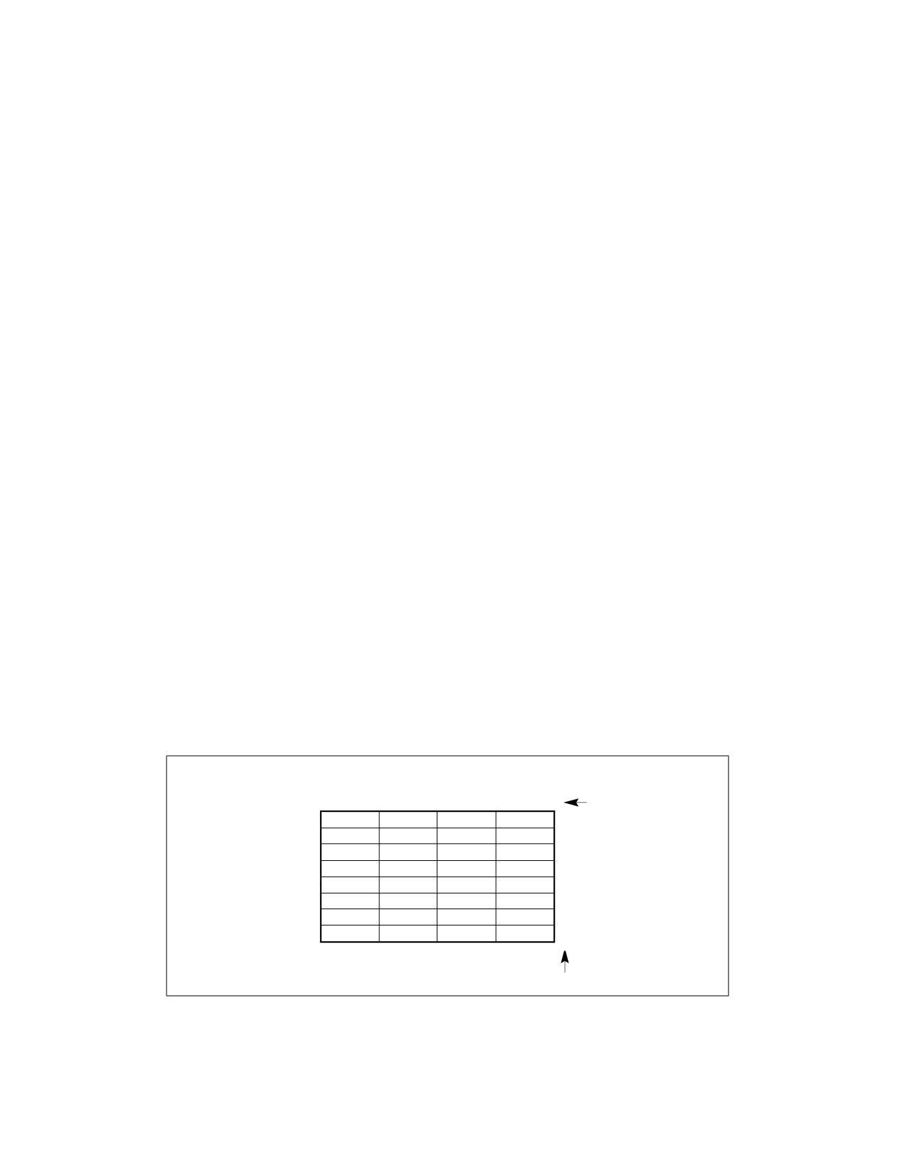
ABOUT THIS MANUAL
the exceptions that may be generated. The instructions are arranged in alphabetical order. General-purpose, x87
FPU, Intel MMX™ technology, SSE/SSE2/SSE3/SSSE3/SSE4 extensions, and system instructions are included.
Chapter 4 — Instruction Set Reference, M-U. Continues the description of Intel 64 and IA-32 instructions
started in Chapter 3. It starts Intel® 64 and IA-32 Architectures Software Developer’s Manual, Volume 2B.
Chapter 5 — Instruction Set Reference, V. Continues the description of Intel 64 and IA-32 instructions started
in chapters 3 and 4. This chapter starts Intel® 64 and IA-32 Architectures Software Developer’s Manual, Volume
2C.
Chapter 6 — Instruction Set Reference, W-Z. Continues the description of Intel 64 and IA-32 instructions
started in chapters 3, 4, and 5. It provides the balance of the alphabetized list of instructions and starts Intel® 64
and IA-32 Architectures Software Developer’s Manual, Volume 2D.
Chapter 7 — Safer Mode Extensions Reference. Describes the safer mode extensions (SMX). SMX is intended
for a system executive to support launching a measured environment in a platform where the identity of the soft-
ware controlling the platform hardware can be measured for the purpose of making trust decisions.
Chapter 8— Instruction Set Reference Unique to Intel® Xeon Phi™ Processors. Describes the instruction
set that is unique to Intel® Xeon Phi™ processors based on the Knights Landing and Knights Mill microarchitec-
tures. The set is not supported in any other Intel processors.
Appendix A — Opcode Map. Gives an opcode map for the IA-32 instruction set.
Appendix B — Instruction Formats and Encodings. Gives the binary encoding of each form of each IA-32
instruction.
Appendix C — Intel® C/C++ Compiler Intrinsics and Functional Equivalents. Lists the Intel® C/C++ compiler
intrinsics and their assembly code equivalents for each of the IA-32 MMX and SSE/SSE2/SSE3 instructions.
1.3
NOTATIONAL CONVENTIONS
This manual uses specific notation for data-structure formats, for symbolic representation of instructions, and for
hexadecimal and binary numbers. A review of this notation makes the manual easier to read.
1.3.1
Bit and Byte Order
In illustrations of data structures in memory, smaller addresses appear toward the bottom of the figure; addresses
increase toward the top. Bit positions are numbered from right to left. The numerical value of a set bit is equal to
two raised to the power of the bit position. IA-32 processors are “little endian” machines; this means the bytes of
a word are numbered starting from the least significant byte. Figure 1-1 illustrates these conventions.
Highest
Data Structure
Address
31
24 23
16 15
8 7
0
Bit offset
28
24
20
16
12
8
4
Lowest
Byte 3
Byte 2
Byte 1
Byte 0
0
Address
Byte Offset
Figure 1-1. Bit and Byte Order
Vol. 2A
1-5
ABOUT THIS MANUAL
1.3.2
Reserved Bits and Software Compatibility
In many register and memory layout descriptions, certain bits are marked as reserved. When bits are marked as
reserved, it is essential for compatibility with future processors that software treat these bits as having a future,
though unknown, effect. The behavior of reserved bits should be regarded as not only undefined, but unpredict-
able. Software should follow these guidelines in dealing with reserved bits:
• Do not depend on the states of any reserved bits when testing the values of registers which contain such bits.
Mask out the reserved bits before testing.
• Do not depend on the states of any reserved bits when storing to memory or to a register.
• Do not depend on the ability to retain information written into any reserved bits.
• When loading a register, always load the reserved bits with the values indicated in the documentation, if any, or
reload them with values previously read from the same register.
NOTE
Avoid any software dependence upon the state of reserved bits in IA-32 registers. Depending upon
the values of reserved register bits will make software dependent upon the unspecified manner in
which the processor handles these bits. Programs that depend upon reserved values risk incompat-
ibility with future processors.
1.3.3
Instruction Operands
When instructions are represented symbolically, a subset of the IA-32 assembly language is used. In this subset,
an instruction has the following format:
label: mnemonic argument1, argument2, argument3
where:
• A label is an identifier which is followed by a colon.
• A mnemonic is a reserved name for a class of instruction opcodes which have the same function.
• The operands argument1, argument2, and argument3 are optional. There may be from zero to three operands,
depending on the opcode. When present, they take the form of either literals or identifiers for data items.
Operand identifiers are either reserved names of registers or are assumed to be assigned to data items
declared in another part of the program (which may not be shown in the example).
When two operands are present in an arithmetic or logical instruction, the right operand is the source and the left
operand is the destination.
For example:
LOADREG: MOV EAX, SUBTOTAL
In this example, LOADREG is a label, MOV is the mnemonic identifier of an opcode, EAX is the destination operand,
and SUBTOTAL is the source operand. Some assembly languages put the source and destination in reverse order.
1.3.4
Hexadecimal and Binary Numbers
Base 16 (hexadecimal) numbers are represented by a string of hexadecimal digits followed by the character H (for
example, F82EH). A hexadecimal digit is a character from the following set: 0, 1, 2, 3, 4, 5, 6, 7, 8, 9, A, B, C, D,
E, and F.
Base 2 (binary) numbers are represented by a string of 1s and 0s, sometimes followed by the character B (for
example, 1010B). The “B” designation is only used in situations where confusion as to the type of number might
arise.
1-6
Vol. 2A
ABOUT THIS MANUAL
1.3.5
Segmented Addressing
The processor uses byte addressing. This means memory is organized and accessed as a sequence of bytes.
Whether one or more bytes are being accessed, a byte address is used to locate the byte or bytes in memory. The
range of memory that can be addressed is called an address space.
The processor also supports segmented addressing. This is a form of addressing where a program may have many
independent address spaces, called segments. For example, a program can keep its code (instructions) and stack
in separate segments. Code addresses would always refer to the code space, and stack addresses would always
refer to the stack space. The following notation is used to specify a byte address within a segment:
Segment-register:Byte-address
For example, the following segment address identifies the byte at address FF79H in the segment pointed by the DS
register:
DS:FF79H
The following segment address identifies an instruction address in the code segment. The CS register points to the
code segment and the EIP register contains the address of the instruction.
CS:EIP
1.3.6
Exceptions
An exception is an event that typically occurs when an instruction causes an error. For example, an attempt to
divide by zero generates an exception. However, some exceptions, such as breakpoints, occur under other condi-
tions. Some types of exceptions may provide error codes. An error code reports additional information about the
error. An example of the notation used to show an exception and error code is shown below:
#PF(fault code)
This example refers to a page-fault exception under conditions where an error code naming a type of fault is
reported. Under some conditions, exceptions which produce error codes may not be able to report an accurate
code. In this case, the error code is zero, as shown below for a general-protection exception:
#GP(0)
1.3.7
A New Syntax for CPUID, CR, and MSR Values
Obtain feature flags, status, and system information by using the CPUID instruction, by checking control register
bits, and by reading model-specific registers. We are moving toward a new syntax to represent this information.
See Figure 1-2.
Vol. 2A
1-7
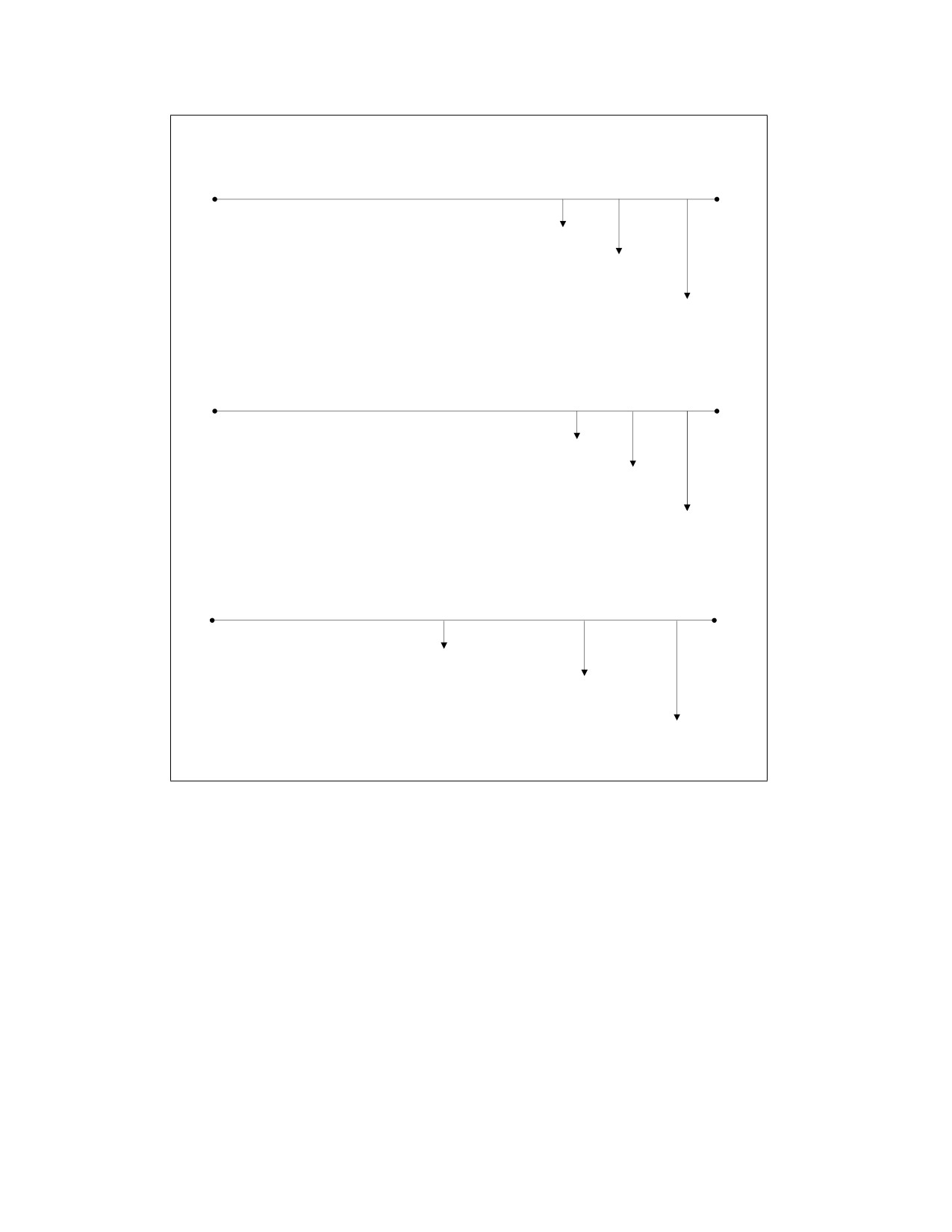
ABOUT THIS MANUAL
CPUID Input and Output
CPUID.01H:EDX.SSE[bit 25] = 1
Input value for EAX register
Output register and feature flag or field
name with bit position(s)
Value (or range) of output
Control Register Values
CR4.OSFXSR[bit 9] = 1
Example CR name
Feature flag or field name
with bit position(s)
Value (or range) of output
Model-Specific Register Values
IA32_MISC_ENABLE.ENABLEFOPCODE[bit 2] = 1
Example MSR name
Feature flag or field name with bit position(s)
Value (or range) of output
SDM29002
Figure 1-2. Syntax for CPUID, CR, and MSR Data Presentation
1.4
RELATED LITERATURE
Literature related to Intel 64 and IA-32 processors is listed and viewable on-line at:
See also:
• The latest security information on Intel® products:
• Software developer resources, guidance, and insights for security advisories:
• The data sheet for a particular Intel 64 or IA-32 processor
• The specification update for a particular Intel 64 or IA-32 processor
• Intel® C++ Compiler documentation and online help:
1-8
Vol. 2A
ABOUT THIS MANUAL
• Intel® Fortran Compiler documentation and online help:
• Intel® Software Development Tools:
• Intel® 64 and IA-32 Architectures Software Developer’s Manual (in one, four or ten volumes):
• Intel® 64 and IA-32 Architectures Optimization Reference Manual:
• Intel® Trusted Execution Technology Measured Launched Environment Programming Guide:
http://www.intel.com/content/www/us/en/software-developers/intel-txt-software-development-guide.html
• Intel® Software Guard Extensions (Intel® SGX) Information
• Developing Multi-threaded Applications: A Platform Consistent Approach:
tions.pdf
• Using Spin-Loops on Intel® Pentium® 4 Processor and Intel® Xeon® Processor:
• Performance Monitoring Unit Sharing Guide
Literature related to select features in future Intel processors are available at:
• Intel® Architecture Instruction Set Extensions Programming Reference
More relevant links are:
• Intel® Developer Zone:
• Developer centers:
• Processor support general link:
• Intel® Hyper-Threading Technology (Intel® HT Technology):
Vol. 2A
1-9
ABOUT THIS MANUAL
1-10
Vol. 2A
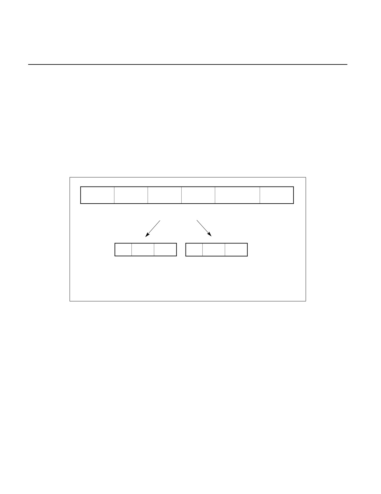
CHAPTER 2
INSTRUCTION FORMAT
This chapter describes the instruction format for all Intel 64 and IA-32 processors. The instruction format for
protected mode, real-address mode and virtual-8086 mode is described in Section 2.1. Increments provided for IA-
32e mode and its sub-modes are described in Section 2.2.
2.1
INSTRUCTION FORMAT FOR PROTECTED MODE, REAL-ADDRESS MODE,
AND VIRTUAL-8086 MODE
The Intel 64 and IA-32 architectures instruction encodings are subsets of the format shown in Figure 2-1. Instruc-
tions consist of optional instruction prefixes (in any order), primary opcode bytes (up to three bytes), an
addressing-form specifier (if required) consisting of the ModR/M byte and sometimes the SIB (Scale-Index-Base)
byte, a displacement (if required), and an immediate data field (if required).
Instruction
Opcode
ModR/M
SIB
Displacement
Immediate
Prefixes
Prefixes of
1-, 2-, or 3-byte
1 byte
1 byte
Address
Immediate
1 byte each
opcode
(if required)
(if required)
displacement
data of
(optional)1, 2
of 1, 2, or 4
1, 2, or 4
bytes or none3
bytes or none3
7
6 5
3
2
0
7
6 5
3
2
0
Reg/
Mod
R/M
Scale
Index
Base
Opcode
1. The REX prefix is optional, but if used must be immediately before the opcode; see Section
2.2.1, “REX Prefixes” for additional information.
2. For VEX encoding information, see Section 2.3, “Intel® Advanced Vector Extensions (Intel®
AVX)”.
3. Some rare instructions can take an 8B immediate or 8B displacement.
Figure 2-1. Intel 64 and IA-32 Architectures Instruction Format
2.1.1
Instruction Prefixes
Instruction prefixes are divided into four groups, each with a set of allowable prefix codes. For each instruction, it
is only useful to include up to one prefix code from each of the four groups (Groups 1, 2, 3, 4). Groups 1 through 4
may be placed in any order relative to each other.
• Group 1
— Lock and repeat prefixes:
• LOCK prefix is encoded using F0H.
• REPNE/REPNZ prefix is encoded using F2H. Repeat-Not-Zero prefix applies only to string and
input/output instructions. (F2H is also used as a mandatory prefix for some instructions.)
• REP or REPE/REPZ is encoded using F3H. The repeat prefix applies only to string and input/output
instructions. (F3H is also used as a mandatory prefix for some instructions.)
Vol. 2A
2-1

INSTRUCTION FORMAT
— BND prefix is encoded using F2H if the following conditions are true:
• CPUID.(EAX=07H, ECX=0):EBX.MPX[bit 14] is set.
• BNDCFGU.EN and/or IA32_BNDCFGS.EN is set.
• When the F2 prefix precedes a near CALL, a near RET, a near JMP, a short Jcc, or a near Jcc instruction
(see Appendix E, “Intel® Memory Protection Extensions,” of the Intel® 64 and IA-32 Architectures
Software Developer’s Manual, Volume 1).
•
Group 2
— Segment override prefixes:
•
2EH—CS segment override (use with any branch instruction is reserved).
•
36H—SS segment override prefix (use with any branch instruction is reserved).
•
3EH—DS segment override prefix (use with any branch instruction is reserved).
•
26H—ES segment override prefix (use with any branch instruction is reserved).
•
64H—FS segment override prefix (use with any branch instruction is reserved).
•
65H—GS segment override prefix (use with any branch instruction is reserved).
— Branch hints1:
•
2EH—Branch not taken (used only with Jcc instructions).
•
3EH—Branch taken (used only with Jcc instructions).
•
Group 3
• Operand-size override prefix is encoded using 66H (66H is also used as a mandatory prefix for some
instructions).
•
Group 4
•
67H—Address-size override prefix.
The LOCK prefix (F0H) forces an operation that ensures exclusive use of shared memory in a multiprocessor envi-
ronment. See “LOCK—Assert LOCK# Signal Prefix” in Chapter 3, “Instruction Set Reference, A-L,” for a description
of this prefix.
Repeat prefixes (F2H, F3H) cause an instruction to be repeated for each element of a string. Use these prefixes
only with string and I/O instructions (MOVS, CMPS, SCAS, LODS, STOS, INS, and OUTS). Use of repeat prefixes
and/or undefined opcodes with other Intel 64 or IA-32 instructions is reserved; such use may cause unpredictable
behavior.
Some instructions may use F2H,F3H as a mandatory prefix to express distinct functionality.
Branch hint prefixes (2EH, 3EH) allow a program to give a hint to the processor about the most likely code path for
a branch. Use these prefixes only with conditional branch instructions (Jcc). Other use of branch hint prefixes
and/or other undefined opcodes with Intel 64 or IA-32 instructions is reserved; such use may cause unpredictable
behavior.
The operand-size override prefix allows a program to switch between 16- and 32-bit operand sizes. Either size can
be the default; use of the prefix selects the non-default size.
Some SSE2/SSE3/SSSE3/SSE4 instructions and instructions using a three-byte sequence of primary opcode bytes
may use 66H as a mandatory prefix to express distinct functionality.
Other use of the 66H prefix is reserved; such use may cause unpredictable behavior.
The address-size override prefix (67H) allows programs to switch between 16- and 32-bit addressing. Either size
can be the default; the prefix selects the non-default size. Using this prefix and/or other undefined opcodes when
operands for the instruction do not reside in memory is reserved; such use may cause unpredictable behavior.
1. Some earlier microarchitectures used these as branch hints, but recent generations have not and they are reserved for future hint
usage.
2-2
Vol. 2A
INSTRUCTION FORMAT
2.1.2
Opcodes
A primary opcode can be 1, 2, or 3 bytes in length. An additional 3-bit opcode field is sometimes encoded in the
ModR/M byte. Smaller fields can be defined within the primary opcode. Such fields define the direction of opera-
tion, size of displacements, register encoding, condition codes, or sign extension. Encoding fields used by an
opcode vary depending on the class of operation.
Two-byte opcode formats for general-purpose and SIMD instructions consist of one of the following:
• An escape opcode byte 0FH as the primary opcode and a second opcode byte.
• A mandatory prefix (66H, F2H, or F3H), an escape opcode byte, and a second opcode byte (same as previous
bullet).
For example, CVTDQ2PD consists of the following sequence: F3 0F E6. The first byte is a mandatory prefix (it is not
considered as a repeat prefix).
Three-byte opcode formats for general-purpose and SIMD instructions consist of one of the following:
• An escape opcode byte 0FH as the primary opcode, plus two additional opcode bytes.
• A mandatory prefix (66H, F2H, or F3H), an escape opcode byte, plus two additional opcode bytes (same as
previous bullet).
For example, PHADDW for XMM registers consists of the following sequence: 66 0F 38 01. The first byte is the
mandatory prefix.
Valid opcode expressions are defined in Appendix A and Appendix B.
2.1.3
ModR/M and SIB Bytes
Many instructions that refer to an operand in memory have an addressing-form specifier byte (called the ModR/M
byte) following the primary opcode. The ModR/M byte contains three fields of information:
• The mod field combines with the r/m field to form 32 possible values: eight registers and 24 addressing modes.
• The reg/opcode field specifies either a register number or three more bits of opcode information. The purpose
of the reg/opcode field is specified in the primary opcode.
• The r/m field can specify a register as an operand or it can be combined with the mod field to encode an
addressing mode. Sometimes, certain combinations of the mod field and the r/m field are used to express
opcode information for some instructions.
Certain encodings of the ModR/M byte require a second addressing byte (the SIB byte). The base-plus-index and
scale-plus-index forms of 32-bit addressing require the SIB byte. The SIB byte includes the following fields:
• The scale field specifies the scale factor.
• The index field specifies the register number of the index register.
• The base field specifies the register number of the base register.
See Section 2.1.5 for the encodings of the ModR/M and SIB bytes.
2.1.4
Displacement and Immediate Bytes
Some addressing forms include a displacement immediately following the ModR/M byte (or the SIB byte if one is
present). If a displacement is required, it can be 1, 2, or 4 bytes.
If an instruction specifies an immediate operand, the operand always follows any displacement bytes. An imme-
diate operand can be 1, 2 or 4 bytes.
Vol. 2A
2-3

INSTRUCTION FORMAT
2.1.5
Addressing-Mode Encoding of ModR/M and SIB Bytes
The values and corresponding addressing forms of the ModR/M and SIB bytes are shown in Table 2-1 through Table
2-3: 16-bit addressing forms specified by the ModR/M byte are in Table 2-1 and 32-bit addressing forms are in
Table 2-2. Table 2-3 shows 32-bit addressing forms specified by the SIB byte. In cases where the reg/opcode field
in the ModR/M byte represents an extended opcode, valid encodings are shown in Appendix B.
In Table 2-1 and Table 2-2, the Effective Address column lists 32 effective addresses that can be assigned to the
first operand of an instruction by using the Mod and R/M fields of the ModR/M byte. The first 24 options provide
ways of specifying a memory location; the last eight (Mod = 11B) provide ways of specifying general-purpose, MMX
technology and XMM registers.
The Mod and R/M columns in Table 2-1 and Table 2-2 give the binary encodings of the Mod and R/M fields required
to obtain the effective address listed in the first column. For example: see the row indicated by Mod = 11B, R/M =
000B. The row identifies the general-purpose registers EAX, AX or AL; MMX technology register MM0; or XMM
register XMM0. The register used is determined by the opcode byte and the operand-size attribute.
Now look at the seventh row in either table (labeled “REG =”). This row specifies the use of the 3-bit Reg/Opcode
field when the field is used to give the location of a second operand. The second operand must be a general-
purpose, MMX technology, or XMM register. Rows one through five list the registers that may correspond to the
value in the table. Again, the register used is determined by the opcode byte along with the operand-size attribute.
If the instruction does not require a second operand, then the Reg/Opcode field may be used as an opcode exten-
sion. This use is represented by the sixth row in the tables (labeled “/digit (Opcode)”). Note that values in row six
are represented in decimal form.
The body of Table 2-1 and Table 2-2 (under the label “Value of ModR/M Byte (in Hexadecimal)”) contains a 32 by
8 array that presents all of 256 values of the ModR/M byte (in hexadecimal). Bits 3, 4, and 5 are specified by the
column of the table in which a byte resides. The row specifies bits 0, 1, and 2; and bits 6 and 7. The figure below
demonstrates interpretation of one table value.
Mod
11
RM
000
/digit (Opcode); REG =
001
C8H
11001000
Figure 2-2. Table Interpretation of ModR/M Byte (C8H)
2-4
Vol. 2A

INSTRUCTION FORMAT
Table 2-1. 16-Bit Addressing Forms with the ModR/M Byte
r8(/r)
AL
CL
DL
BL
AH
CH
DH
BH
r16(/r)
AX
CX
DX
BX
SP
BP1
SI
DI
r32(/r)
EAX
ECX
EDX
EBX
ESP
EBP
ESI
EDI
mm(/r)
MM0
MM1
MM2
MM3
MM4
MM5
MM6
MM7
xmm(/r)
XMM0
XMM1
XMM2
XMM3
XMM4
XMM5
XMM6
XMM7
(In decimal) /digit (Opcode)
0
1
2
3
4
5
6
7
(In binary) REG =
000
001
010
011
100
101
110
111
Effective Address
Mod
R/M
Value of ModR/M Byte (in Hexadecimal)
[BX+SI]
00
000
00
08
10
18
20
28
30
38
[BX+DI]
001
01
09
11
19
21
29
31
39
[BP+SI]
010
02
0A
12
1A
22
2A
32
3A
[BP+DI]
011
03
0B
13
1B
23
2B
33
3B
[SI]
100
04
0C
14
1C
24
2C
34
3C
[DI]
101
05
0D
15
1D
25
2D
35
3D
disp162
110
06
0E
16
1E
26
2E
36
3E
[BX]
111
07
0F
17
1F
27
2F
37
3F
[BX+SI]+disp83
01
000
40
48
50
58
60
68
70
78
[BX+DI]+disp8
001
41
49
51
59
61
69
71
79
[BP+SI]+disp8
010
42
4A
52
5A
62
6A
72
7A
[BP+DI]+disp8
011
43
4B
53
5B
63
6B
73
7B
[SI]+disp8
100
44
4C
54
5C
64
6C
74
7C
[DI]+disp8
101
45
4D
55
5D
65
6D
75
7D
[BP]+disp8
110
46
4E
56
5E
66
6E
76
7E
[BX]+disp8
111
47
4F
57
5F
67
6F
77
7F
[BX+SI]+disp16
10
000
80
88
90
98
A0
A8
B0
B8
[BX+DI]+disp16
001
81
89
91
99
A1
A9
B1
B9
[BP+SI]+disp16
010
82
8A
92
9A
A2
AA
B2
BA
[BP+DI]+disp16
011
83
8B
93
9B
A3
AB
B3
BB
[SI]+disp16
100
84
8C
94
9C
A4
AC
B4
BC
[DI]+disp16
101
85
8D
95
9D
A5
AD
B5
BD
[BP]+disp16
110
86
8E
96
9E
A6
AE
B6
BE
[BX]+disp16
111
87
8F
97
9F
A7
AF
B7
BF
EAX/AX/AL/MM0/XMM0
11
000
C0
C8
D0
D8
E0
E8
F0
F8
ECX/CX/CL/MM1/XMM1
001
C1
C9
D1
D9
E1
E9
F1
F9
EDX/DX/DL/MM2/XMM2
010
C2
CA
D2
DA
E2
EA
F2
FA
EBX/BX/BL/MM3/XMM3
011
C3
CB
D3
DB
E3
EB
F3
FB
ESP/SP/AHMM4/XMM4
100
C4
CC
D4
DC
E4
EC
F4
FC
EBP/BP/CH/MM5/XMM5
101
C5
CD
D5
DD
E5
ED
F5
FD
ESI/SI/DH/MM6/XMM6
110
C6
CE
D6
DE
E6
EE
F6
FE
EDI/DI/BH/MM7/XMM7
111
C7
CF
D7
DF
E7
EF
F7
FF
NOTES:
1. The default segment register is SS for the effective addresses containing a BP index, DS for other effective addresses.
2. The disp16 nomenclature denotes a 16-bit displacement that follows the ModR/M byte and that is added to the index.
3. The disp8 nomenclature denotes an 8-bit displacement that follows the ModR/M byte and that is sign-extended and added to the
index.
Vol. 2A
2-5

INSTRUCTION FORMAT
Table 2-2. 32-Bit Addressing Forms with the ModR/M Byte
r8(/r)
AL
CL
DL
BL
AH
CH
DH
BH
r16(/r)
AX
CX
DX
BX
SP
BP
SI
DI
r32(/r)
EAX
ECX
EDX
EBX
ESP
EBP
ESI
EDI
mm(/r)
MM0
MM1
MM2
MM3
MM4
MM5
MM6
MM7
xmm(/r)
XMM0
XMM1
XMM2
XMM3
XMM4
XMM5
XMM6
XMM7
(In decimal) /digit (Opcode)
0
1
2
3
4
5
6
7
(In binary) REG =
000
001
010
011
100
101
110
111
Effective Address
Mod
R/M
Value of ModR/M Byte (in Hexadecimal)
[EAX]
00
000
00
08
10
18
20
28
30
38
[ECX]
001
01
09
11
19
21
29
31
39
[EDX]
010
02
0A
12
1A
22
2A
32
3A
[EBX]
011
03
0B
13
1B
23
2B
33
3B
[--][--]1
100
04
0C
14
1C
24
2C
34
3C
disp322
101
05
0D
15
1D
25
2D
35
3D
[ESI]
110
06
0E
16
1E
26
2E
36
3E
[EDI]
111
07
0F
17
1F
27
2F
37
3F
[EAX]+disp83
01
000
40
48
50
58
60
68
70
78
[ECX]+disp8
001
41
49
51
59
61
69
71
79
[EDX]+disp8
010
42
4A
52
5A
62
6A
72
7A
[EBX]+disp8
011
43
4B
53
5B
63
6B
73
7B
[--][--]+disp8
100
44
4C
54
5C
64
6C
74
7C
[EBP]+disp8
101
45
4D
55
5D
65
6D
75
7D
[ESI]+disp8
110
46
4E
56
5E
66
6E
76
7E
[EDI]+disp8
111
47
4F
57
5F
67
6F
77
7F
[EAX]+disp32
10
000
80
88
90
98
A0
A8
B0
B8
[ECX]+disp32
001
81
89
91
99
A1
A9
B1
B9
[EDX]+disp32
010
82
8A
92
9A
A2
AA
B2
BA
[EBX]+disp32
011
83
8B
93
9B
A3
AB
B3
BB
[--][--]+disp32
100
84
8C
94
9C
A4
AC
B4
BC
[EBP]+disp32
101
85
8D
95
9D
A5
AD
B5
BD
[ESI]+disp32
110
86
8E
96
9E
A6
AE
B6
BE
[EDI]+disp32
111
87
8F
97
9F
A7
AF
B7
BF
EAX/AX/AL/MM0/XMM0
11
000
C0
C8
D0
D8
E0
E8
F0
F8
ECX/CX/CL/MM/XMM1
001
C1
C9
D1
D9
E1
E9
F1
F9
EDX/DX/DL/MM2/XMM2
010
C2
CA
D2
DA
E2
EA
F2
FA
EBX/BX/BL/MM3/XMM3
011
C3
CB
D3
DB
E3
EB
F3
FB
ESP/SP/AH/MM4/XMM4
100
C4
CC
D4
DC
E4
EC
F4
FC
EBP/BP/CH/MM5/XMM5
101
C5
CD
D5
DD
E5
ED
F5
FD
ESI/SI/DH/MM6/XMM6
110
C6
CE
D6
DE
E6
EE
F6
FE
EDI/DI/BH/MM7/XMM7
111
C7
CF
D7
DF
E7
EF
F7
FF
NOTES:
1. The [--][--] nomenclature means a SIB follows the ModR/M byte.
2. The disp32 nomenclature denotes a 32-bit displacement that follows the ModR/M byte (or the SIB byte if one is present) and that is
added to the index.
3. The disp8 nomenclature denotes an 8-bit displacement that follows the ModR/M byte (or the SIB byte if one is present) and that is
sign-extended and added to the index.
Table 2-3 is organized to give 256 possible values of the SIB byte (in hexadecimal). General purpose registers used
as a base are indicated across the top of the table, along with corresponding values for the SIB byte’s base field.
Table rows in the body of the table indicate the register used as the index (SIB byte bits 3, 4, and 5) and the scaling
factor (determined by SIB byte bits 6 and 7).
2-6
Vol. 2A

INSTRUCTION FORMAT
Table 2-3. 32-Bit Addressing Forms with the SIB Byte
r32
EAX
ECX
EDX
EBX
ESP
[*]
ESI
EDI
(In decimal) Base =
0
1
2
3
4
5
6
7
(In binary) Base =
000
001
010
011
100
101
110
111
Scaled Index
SS
Index
Value of SIB Byte (in Hexadecimal)
[EAX]
00
000
00
01
02
03
04
05
06
07
[ECX]
001
08
09
0A
0B
0C
0D
0E
0F
[EDX]
010
10
11
12
13
14
15
16
17
[EBX]
011
18
19
1A
1B
1C
1D
1E
1F
none
100
20
21
22
23
24
25
26
27
[EBP]
101
28
29
2A
2B
2C
2D
2E
2F
[ESI]
110
30
31
32
33
34
35
36
37
[EDI]
111
38
39
3A
3B
3C
3D
3E
3F
[EAX*2]
01
000
40
41
42
43
44
45
46
47
[ECX*2]
001
48
49
4A
4B
4C
4D
4E
4F
[EDX*2]
010
50
51
52
53
54
55
56
57
[EBX*2]
011
58
59
5A
5B
5C
5D
5E
5F
none
100
60
61
62
63
64
65
66
67
[EBP*2]
101
68
69
6A
6B
6C
6D
6E
6F
[ESI*2]
110
70
71
72
73
74
75
76
77
[EDI*2]
111
78
79
7A
7B
7C
7D
7E
7F
[EAX*4]
10
000
80
81
82
83
84
85
86
87
[ECX*4]
001
88
89
8A
8B
8C
8D
8E
8F
[EDX*4]
010
90
91
92
93
94
95
96
97
[EBX*4]
011
98
99
9A
9B
9C
9D
9E
9F
none
100
A0
A1
A2
A3
A4
A5
A6
A7
[EBP*4]
101
A8
A9
AA
AB
AC
AD
AE
AF
[ESI*4]
110
B0
B1
B2
B3
B4
B5
B6
B7
[EDI*4]
111
B8
B9
BA
BB
BC
BD
BE
BF
[EAX*8]
11
000
C0
C1
C2
C3
C4
C5
C6
C7
[ECX*8]
001
C8
C9
CA
CB
CC
CD
CE
CF
[EDX*8]
010
D0
D1
D2
D3
D4
D5
D6
D7
[EBX*8]
011
D8
D9
DA
DB
DC
DD
DE
DF
none
100
E0
E1
E2
E3
E4
E5
E6
E7
[EBP*8]
101
E8
E9
EA
EB
EC
ED
EE
EF
[ESI*8]
110
F0
F1
F2
F3
F4
F5
F6
F7
[EDI*8]
111
F8
F9
FA
FB
FC
FD
FE
FF
NOTES:
1. The [*] nomenclature means a disp32 with no base if the MOD is 00B. Otherwise, [*] means disp8 or disp32 + [EBP]. This provides the
following address modes:
MOD bits Effective Address
00
[scaled index] + disp32
01
[scaled index] + disp8 + [EBP]
10
[scaled index] + disp32 + [EBP]
2.2
IA-32E MODE
IA-32e mode has two sub-modes. These are:
• Compatibility Mode. Enables a 64-bit operating system to run most legacy protected mode software
unmodified.
•
64-Bit Mode. Enables a 64-bit operating system to run applications written to access 64-bit address space.
2.2.1
REX Prefixes
REX prefixes are instruction-prefix bytes used in 64-bit mode. They do the following:
• Specify GPRs and SSE registers.
Vol. 2A
2-7

INSTRUCTION FORMAT
• Specify 64-bit operand size.
• Specify extended control registers.
Not all instructions require a REX prefix in 64-bit mode. A prefix is necessary only if an instruction references one
of the extended registers or uses a 64-bit operand. If a REX prefix is used when it has no meaning, it is ignored.
Only one REX prefix is allowed per instruction. If used, the REX prefix byte must immediately precede the opcode
byte or the escape opcode byte (0FH). When a REX prefix is used in conjunction with an instruction containing a
mandatory prefix, the mandatory prefix must come before the REX so the REX prefix can be immediately preceding
the opcode or the escape byte. For example, CVTDQ2PD with a REX prefix should have REX placed between F3 and
0F E6. Other placements are ignored. The instruction-size limit of 15 bytes still applies to instructions with a REX
prefix. See Figure 2-3.
Legacy
REX
Opcode
ModR/M
SIB
Displacement
Immediate
Prefixes
Prefix
(optional)
1-, 2-, or
1 byte
Address
Immediate data
1 byte
Grp 1,
Grp
3-byte
(if required)
displacement of
of 1, 2, or 4
(if required)
2, Grp 3,
Grp 4
opcode
1, 2, or 4 bytes
bytes or none
(optional)
Figure 2-3. Prefix Ordering in 64-bit Mode
2.2.1.1
Encoding
Intel 64 and IA-32 instruction formats specify up to three registers by using 3-bit fields in the encoding, depending
on the format:
• ModR/M: the reg and r/m fields of the ModR/M byte.
• ModR/M with SIB: the reg field of the ModR/M byte, the base and index fields of the SIB (scale, index, base)
byte.
• Instructions without ModR/M: the reg field of the opcode.
In 64-bit mode, these formats do not change. Bits needed to define fields in the 64-bit context are provided by the
addition of REX prefixes.
2.2.1.2
More on REX Prefix Fields
REX prefixes are a set of 16 opcodes that span one row of the opcode map and occupy entries 40H to 4FH. These
opcodes represent valid instructions (INC or DEC) in IA-32 operating modes and in compatibility mode. In 64-bit
mode, the same opcodes represent the instruction prefix REX and are not treated as individual instructions.
The single-byte-opcode forms of the INC/DEC instructions are not available in 64-bit mode. INC/DEC functionality
is still available using ModR/M forms of the same instructions (opcodes FF/0 and FF/1).
See Table 2-4 for a summary of the REX prefix format. Figure 2-4 though Figure 2-7 show examples of REX prefix
fields in use. Some combinations of REX prefix fields are invalid. In such cases, the prefix is ignored. Some addi-
tional information follows:
• Setting REX.W can be used to determine the operand size but does not solely determine operand width. Like
the 66H size prefix, 64-bit operand size override has no effect on byte-specific operations.
• For non-byte operations: if a 66H prefix is used with prefix (REX.W = 1), 66H is ignored.
• If a 66H override is used with REX and REX.W = 0, the operand size is 16 bits.
• REX.R modifies the ModR/M reg field when that field encodes a GPR, SSE, control or debug register. REX.R is
ignored when ModR/M specifies other registers or defines an extended opcode.
• REX.X bit modifies the SIB index field.
2-8
Vol. 2A

INSTRUCTION FORMAT
• REX.B either modifies the base in the ModR/M r/m field or SIB base field; or it modifies the opcode reg field
used for accessing GPRs.
Table 2-4. REX Prefix Fields [BITS: 0100WRXB]
Field Name
Bit Position
Definition
-
7:4
0100
W
3
0 = Operand size determined by CS.D
1 = 64 Bit Operand Size
R
2
Extension of the ModR/M reg field
X
1
Extension of the SIB index field
B
0
Extension of the ModR/M r/m field, SIB base field, or Opcode reg field
ModRM Byte
REX PREFIX
Opcode
mod
reg
r/m
0100WR0B
≠11
rrr
bbb
Rrrr
Bbbb
OM17Xfig1-3
Figure 2-4. Memory Addressing Without an SIB Byte; REX.X Not Used
ModRM Byte
REX PREFIX
Opcode
mod
reg
r/m
0100WR0B
11
rrr
bbb
Rrrr
Bbbb
OM17Xfig1-4
Figure 2-5. Register-Register Addressing (No Memory Operand); REX.X Not Used
Vol. 2A
2-9
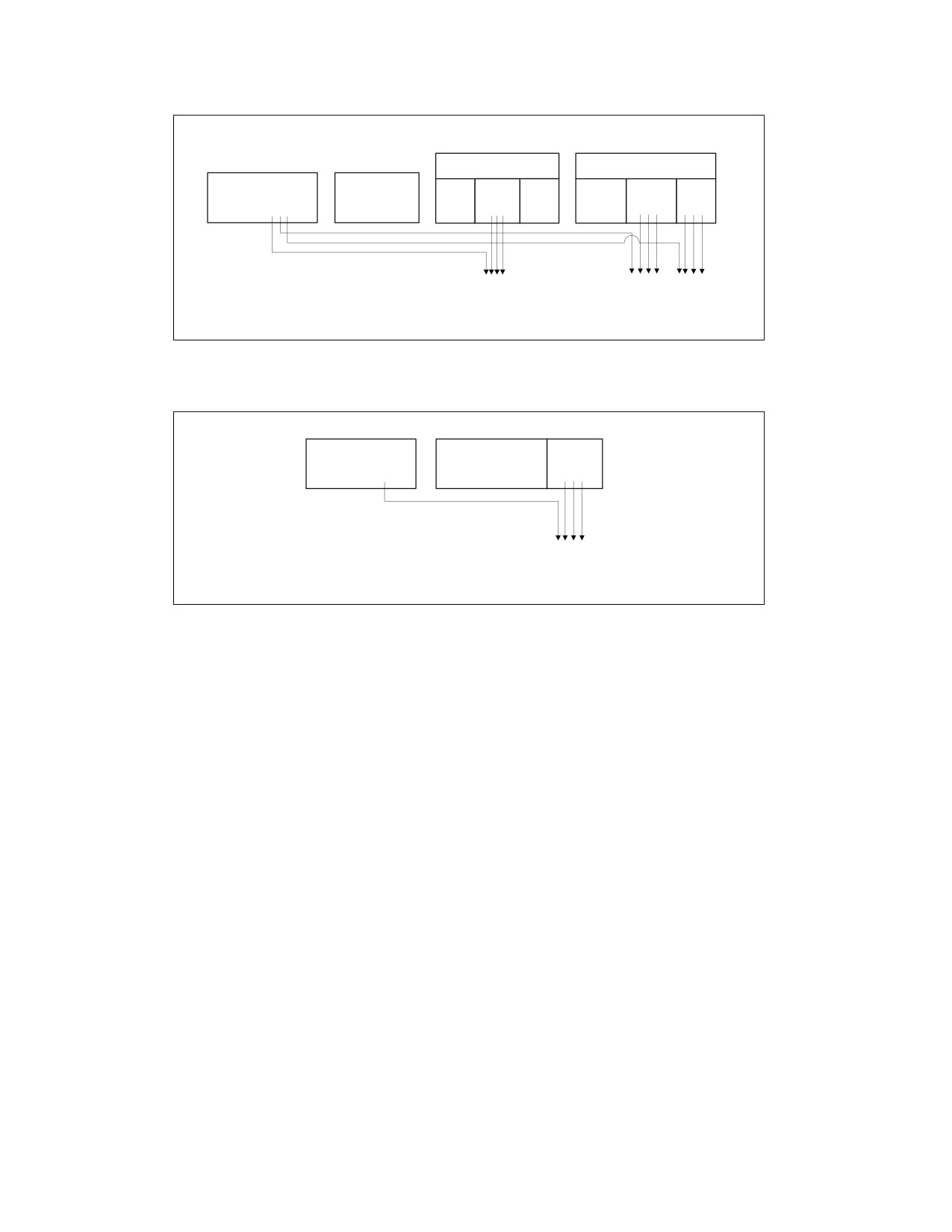
INSTRUCTION FORMAT
ModRM Byte
SIB Byte
REX PREFIX
Opcode
mod
reg
r/m
scale
index
base
0100WRXB
≠ 11
rrr
100
ss
xxx
bbb
Rrrr
Xxxx
Bbbb
OM17Xfig1-5
Figure 2-6. Memory Addressing With a SIB Byte
REX PREFIX
Opcode
reg
0100W00B
bbb
Bbbb
OM17Xfig1-6
Figure 2-7. Register Operand Coded in Opcode Byte; REX.X & REX.R Not Used
In the IA-32 architecture, byte registers (AH, AL, BH, BL, CH, CL, DH, and DL) are encoded in the ModR/M byte’s
reg field, the r/m field or the opcode reg field as registers 0 through 7. REX prefixes provide an additional
addressing capability for byte-registers that makes the least-significant byte of GPRs available for byte operations.
Certain combinations of the fields of the ModR/M byte and the SIB byte have special meaning for register encod-
ings. For some combinations, fields expanded by the REX prefix are not decoded. Table 2-5 describes how each
case behaves.
2-10
Vol. 2A

INSTRUCTION FORMAT
Table 2-5. Special Cases of REX Encodings
ModR/M or
Sub-field
Compatibility Mode
Compatibility Mode
SIB
Encodings
Operation
Implications
Additional Implications
ModR/M Byte
mod ? 11
SIB byte present.
SIB byte required for
REX prefix adds a fourth bit (b) which is not decoded
ESP-based addressing.
(don't care).
r/m =
b*100(ESP)
SIB byte also required for R12-based addressing.
ModR/M Byte
mod = 0
Base register not
EBP without a
REX prefix adds a fourth bit (b) which is not decoded
used.
displacement must be
(don't care).
r/m =
done using
b*101(EBP)
Using RBP or R13 without displacement must be done
mod = 01 with
using mod = 01 with a displacement of 0.
displacement of 0.
SIB Byte
index =
Index register not
ESP cannot be used as
REX prefix adds a fourth bit (b) which is decoded.
0100(ESP)
used.
an index register.
There are no additional implications. The expanded
index field allows distinguishing RSP from R12,
therefore R12 can be used as an index.
SIB Byte
base =
Base register is
Base register depends
REX prefix adds a fourth bit (b) which is not decoded.
0101(EBP)
unused if mod = 0.
on mod encoding.
This requires explicit displacement to be used with
EBP/RBP or R13.
NOTES:
* Don’t care about value of REX.B
2.2.1.3
Displacement
Addressing in 64-bit mode uses existing 32-bit ModR/M and SIB encodings. The ModR/M and SIB displacement
sizes do not change. They remain 8 bits or 32 bits and are sign-extended to 64 bits.
2.2.1.4
Direct Memory-Offset MOVs
In 64-bit mode, direct memory-offset forms of the MOV instruction are extended to specify a 64-bit immediate
absolute address. This address is called a moffset. No prefix is needed to specify this 64-bit memory offset. For
these MOV instructions, the size of the memory offset follows the address-size default (64 bits in 64-bit mode). See
Table 2-6.
Table 2-6. Direct Memory Offset Form of MOV
Opcode
Instruction
A0
MOV AL, moffset
A1
MOV EAX, moffset
A2
MOV moffset, AL
A3
MOV moffset, EAX
2.2.1.5
Immediates
In 64-bit mode, the typical size of immediate operands remains 32 bits. When the operand size is 64 bits, the
processor sign-extends all immediates to 64 bits prior to their use.
Support for 64-bit immediate operands is accomplished by expanding the semantics of the existing move (MOV
reg, imm16/32) instructions. These instructions (opcodes B8H - BFH) move 16-bits or 32-bits of immediate data
(depending on the effective operand size) into a GPR. When the effective operand size is 64 bits, these instructions
can be used to load an immediate into a GPR. A REX prefix is needed to override the 32-bit default operand size to
a 64-bit operand size.
For example:
48 B8
8877665544332211 MOV RAX,1122334455667788H
Vol. 2A
2-11

INSTRUCTION FORMAT
2.2.1.6
RIP-Relative Addressing
A new addressing form, RIP-relative (relative instruction-pointer) addressing, is implemented in 64-bit mode. An
effective address is formed by adding displacement to the 64-bit RIP of the next instruction.
In IA-32 architecture and compatibility mode, addressing relative to the instruction pointer is available only with
control-transfer instructions. In 64-bit mode, instructions that use ModR/M addressing can use RIP-relative
addressing. Without RIP-relative addressing, all ModR/M modes address memory relative to zero.
RIP-relative addressing allows specific ModR/M modes to address memory relative to the 64-bit RIP using a signed
32-bit displacement. This provides an offset range of ±2GB from the RIP. Table 2-7 shows the ModR/M and SIB
encodings for RIP-relative addressing. Redundant forms of 32-bit displacement-addressing exist in the current
ModR/M and SIB encodings. There is one ModR/M encoding and there are several SIB encodings. RIP-relative
addressing is encoded using a redundant form.
In 64-bit mode, the ModR/M Disp32 (32-bit displacement) encoding is re-defined to be RIP+Disp32 rather than
displacement-only. See Table 2-7.
Table 2-7. RIP-Relative Addressing
ModR/M and SIB Sub-field Encodings
Compatibility Mode
64-bit Mode
Additional Implications in 64-bit mode
Operation
Operation
ModR/M Byte
mod = 00
Disp32
RIP + Disp32
In 64-bit mode, if one wants to use a Disp32
without specifying a base register, one can use a
r/m = 101 (none)
SIB byte encoding (indicated by ModR/M.r/m=100)
as described in the next row.
SIB Byte
base = 101 (none)
If mod = 00, Disp32
Same as legacy
None
index = 100 (none)
scale = 0, 1, 2, 4
The ModR/M encoding for RIP-relative addressing does not depend on using a prefix. Specifically, the r/m bit field
encoding of 101B (used to select RIP-relative addressing) is not affected by the REX prefix. For example, selecting
R13 (REX.B = 1, r/m = 101B) with mod = 00B still results in RIP-relative addressing. The 4-bit r/m field of REX.B
combined with ModR/M is not fully decoded. In order to address R13 with no displacement, software must encode
R13 + 0 using a 1-byte displacement of zero.
RIP-relative addressing is enabled by 64-bit mode, not by a 64-bit address-size. The use of the address-size prefix
does not disable RIP-relative addressing. The effect of the address-size prefix is to truncate and zero-extend the
computed effective address to 32 bits.
2.2.1.7
Default 64-Bit Operand Size
In 64-bit mode, two groups of instructions have a default operand size of 64 bits (do not need a REX prefix for this
operand size). These are:
• Near branches.
• All instructions, except far branches, that implicitly reference the RSP.
2.2.2
Additional Encodings for Control and Debug Registers
In 64-bit mode, more encodings for control and debug registers are available. The REX.R bit is used to modify the
ModR/M reg field when that field encodes a control or debug register (see Table 2-4). These encodings enable the
processor to address CR8-CR15 and DR8- DR15. An additional control register (CR8) is defined in 64-bit mode. CR8
becomes the Task Priority Register (TPR).
In the first implementation of IA-32e mode, CR9-CR15 and DR8-DR15 are not implemented. Any attempt to access
unimplemented registers results in an invalid-opcode exception (#UD).
2-12
Vol. 2A