Intel 64 and IA-32 Architectures. Software Developer’s Manual (Collection, 2023) - page 51
ADVANCED PROGRAMMABLE INTERRUPT CONTROLLER (APIC)
63
MAXPHYADDR
12 11109
8
7
0
Reserved
APIC Base
APIC Base-Base physical address
APIC global enable/disable
BSP-Processor is BSP
Reserved
Figure 11-5. IA32_APIC_BASE MSR (APIC_BASE_MSR in P6 Family)
11.4.5 Relocating the Local APIC Registers
The Pentium 4, Intel Xeon, and P6 family processors permit the starting address of the APIC registers to be relo-
cated from FEE00000H to another physical address by modifying the value in the base address field of the
IA32_APIC_BASE MSR. This extension of the APIC architecture is provided to help resolve conflicts with memory
maps of existing systems and to allow individual processors in an MP system to map their APIC registers to
different locations in physical memory.
11.4.6 Local APIC ID
At power up, system hardware assigns a unique APIC ID to each local APIC on the system bus (for Pentium 4 and
Intel Xeon processors) or on the APIC bus (for P6 family and Pentium processors). The hardware assigned APIC ID
is based on system topology and includes encoding for socket position and cluster information (see Figure 9-2 and
Section 9.9.1, “Hierarchical Mapping of Shared Resources”).
In MP systems, the local APIC ID is also used as a processor ID by the BIOS and the operating system. Some
processors permit software to modify the APIC ID. However, the ability of software to modify the APIC ID is
processor model specific. Because of this, operating system software should avoid writing to the local APIC ID
register. The value returned by bits 31-24 of the EBX register (when the CPUID instruction is executed with a
source operand value of 1 in the EAX register) is always the Initial APIC ID (determined by the platform initializa-
tion). This is true even if software has changed the value in the Local APIC ID register.
The processor receives the hardware assigned APIC ID (or Initial APIC ID) by sampling pins A11# and A12# and
pins BR0# through BR3# (for the Pentium 4, Intel Xeon, and P6 family processors) and pins BE0# through BE3#
(for the Pentium processor). The APIC ID latched from these pins is stored in the APIC ID field of the local APIC ID
register (see Figure 11-6), and is used as the Initial APIC ID for the processor.
P6 family and Pentium processors
xAPIC Mode
31
27
24
0
Address: 0FEE0 0020H
Value after reset: 0000 0000H
APIC ID
Reserved
Pentium 4 processors, Xeon processors, and later processors
31
24
0
APIC ID
Reserved
x2APIC Mode
31
0
MSR Address: 802H
x2APIC ID
Figure 11-6. Local APIC ID Register
Vol. 3A
11-9
ADVANCED PROGRAMMABLE INTERRUPT CONTROLLER (APIC)
For the P6 family and Pentium processors, the local APIC ID field in the local APIC ID register is 4 bits. Encodings
0H through EH can be used to uniquely identify 15 different processors connected to the APIC bus. For the Pentium
4 and Intel Xeon processors, the xAPIC specification extends the local APIC ID field to 8 bits. These can be used to
identify up to 255 processors in the system.
11.4.7 Local APIC State
The following sections describe the state of the local APIC and its registers following a power-up or reset, after the
local APIC has been software disabled, following an INIT reset, and following an INIT-deassert message.
x2APIC will introduce 32-bit ID; see Section 11.12.
11.4.7.1 Local APIC State After Power-Up or Reset
Following a power-up or reset of the processor, the state of local APIC and its registers are as follows:
• The following registers are reset to all 0s.
• IRR, ISR, TMR, ICR, LDR, and TPR.
• Timer initial count and timer current count registers.
• Divide configuration register.
• The DFR register is reset to all 1s.
• The LVT register is reset to 0s except for the mask bits; these are set to 1s.
• The local APIC version register is not affected.
• The local APIC ID register is set to a unique APIC ID. (Pentium and P6 family processors only). The Arb ID
register is set to the value in the APIC ID register.
• The spurious-interrupt vector register is initialized to 000000FFH. By setting bit 8 to 0, software disables the
local APIC.
• If the processor is the only processor in the system or it is the BSP in an MP system (see Section 9.4.1, “BSP
and AP Processors”); the local APIC will respond normally to INIT and NMI messages, to INIT# signals and to
STPCLK# signals. If the processor is in an MP system and has been designated as an AP; the local APIC will
respond the same as for the BSP. In addition, it will respond to SIPI messages. For P6 family processors only,
an AP will not respond to a STPCLK# signal.
11.4.7.2 Local APIC State After It Has Been Software Disabled
When the APIC software enable/disable flag in the spurious interrupt vector register has been explicitly cleared (as
opposed to being cleared during a power up or reset), the local APIC is temporarily disabled (see Section 11.4.3,
“Enabling or Disabling the Local APIC”). The operation and response of a local APIC while in this software-disabled
state is as follows:
• The local APIC will respond normally to INIT, NMI, SMI, and SIPI messages.
• Pending interrupts in the IRR and ISR registers are held and require masking or handling by the CPU.
• The local APIC can still issue IPIs. It is software’s responsibility to avoid issuing IPIs through the IPI mechanism
and the ICR register if sending interrupts through this mechanism is not desired.
• The reception of any interrupt or transmission of any IPIs that are in progress when the local APIC is disabled
are completed before the local APIC enters the software-disabled state.
• The mask bits for all the LVT entries are set. Attempts to reset these bits will be ignored.
• (For Pentium and P6 family processors) The local APIC continues to listen to all bus messages in order to keep
its arbitration ID synchronized with the rest of the system.
11.4.7.3 Local APIC State After an INIT Reset (“Wait-for-SIPI” State)
An INIT reset of the processor can be initiated in either of two ways:
11-10
Vol. 3A
ADVANCED PROGRAMMABLE INTERRUPT CONTROLLER (APIC)
• By asserting the processor’s INIT# pin.
• By sending the processor an INIT IPI (an IPI with the delivery mode set to INIT).
Upon receiving an INIT through either of these mechanisms, the processor responds by beginning the initialization
process of the processor core and the local APIC. The state of the local APIC following an INIT reset is the same as
it is after a power-up or hardware reset, except that the APIC ID and arbitration ID registers are not affected. This
state is also referred to at the “wait-for-SIPI” state (see also: Section 9.4.2, “MP Initialization Protocol Require-
ments and Restrictions”).
11.4.7.4 Local APIC State After It Receives an INIT-Deassert IPI
Only the Pentium and P6 family processors support the INIT-deassert IPI. An INIT-deassert IPI has no affect on the
state of the APIC, other than to reload the arbitration ID register with the value in the APIC ID register.
11.4.8 Local APIC Version Register
The local APIC contains a hardwired version register. Software can use this register to identify the APIC version
(see Figure 11-7). In addition, the register specifies the number of entries in the local vector table (LVT) for a
specific implementation.
The fields in the local APIC version register are as follows:
Version
The version numbers of the local APIC:
0XH
82489DX discrete APIC.
10H - 15H
Integrated APIC.
Other values reserved.
Max LVT Entry
Shows the number of LVT entries minus 1. For the Pentium 4 and Intel Xeon processors (which
have 6 LVT entries), the value returned in the Max LVT field is 5; for the P6 family processors
(which have 5 LVT entries), the value returned is 4; for the Pentium processor (which has 4 LVT
entries), the value returned is 3. For processors based on the Nehalem microarchitecture
(which has 7 LVT entries) and onward, the value returned is 6.
Suppress EOI-broadcasts
Indicates whether software can inhibit the broadcast of EOI message by setting bit 12 of the
Spurious Interrupt Vector Register; see Section 11.8.5 and Section 11.9.
31
25 24
23
16
15
8
7
0
Reserved
Max LVT Entry
Reserved
Version
Support for EOI-broadcast suppression
Value after reset: 0BNN 00VVH
V = Version, N = # of LVT entries minus 1,
B = 1 if EOI-broadcast suppression supported
Address: FEE0 0030H
Figure 11-7. Local APIC Version Register
Vol. 3A
11-11
ADVANCED PROGRAMMABLE INTERRUPT CONTROLLER (APIC)
11.5
HANDLING LOCAL INTERRUPTS
The following sections describe facilities that are provided in the local APIC for handling local interrupts. These
include: the processor’s LINT0 and LINT1 pins, the APIC timer, the performance-monitoring counters, Intel
Processor Trace, the thermal sensor, and the internal APIC error detector. Local interrupt handling facilities include:
the LVT, the error status register (ESR), the divide configuration register (DCR), and the initial count and current
count registers.
11.5.1 Local Vector Table
The local vector table (LVT) allows software to specify the manner in which the local interrupts are delivered to the
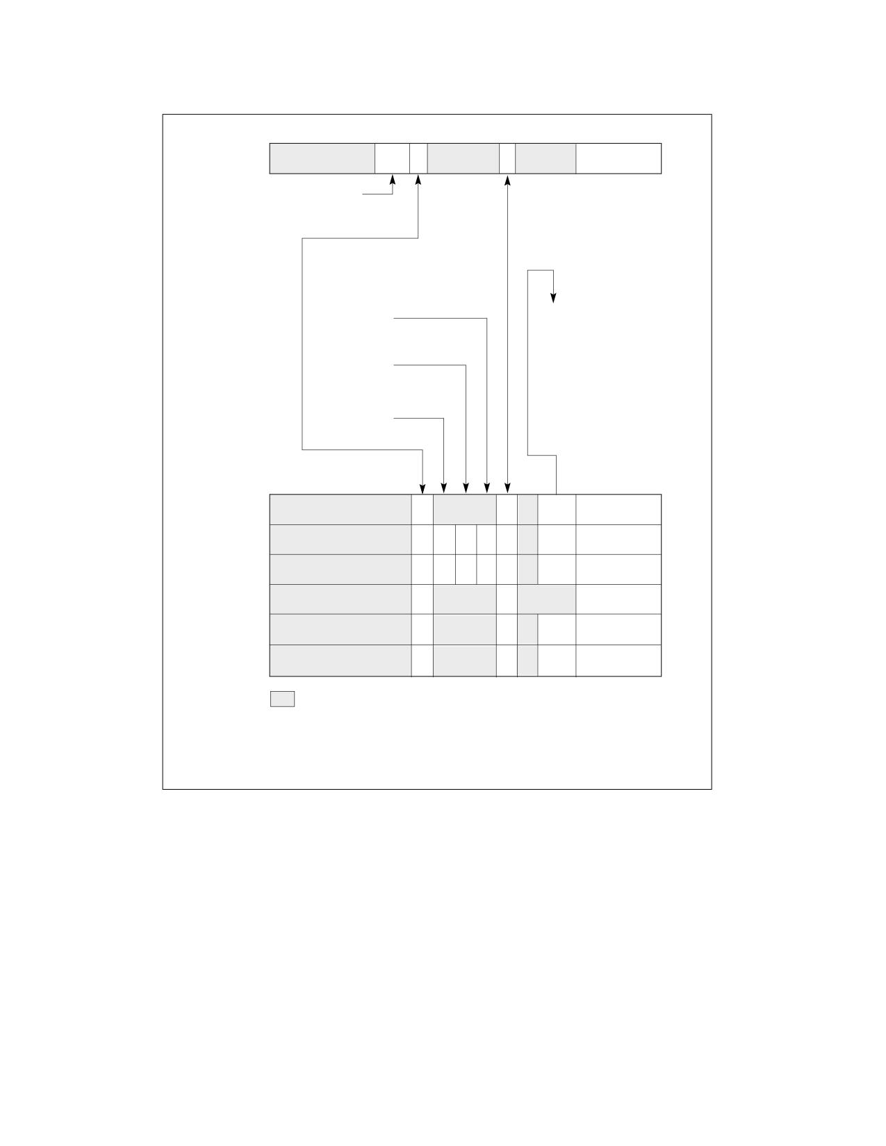
processor core. It consists of the following 32-bit APIC registers (see Figure 11-8), one for each local interrupt:
• LVT CMCI Register (FEE0 02F0H) - Specifies interrupt delivery when an overflow condition of corrected
machine check error count reaching a threshold value occurred in a machine check bank supporting CMCI (see
Section 16.5.1, “CMCI Local APIC Interface”).
• LVT Timer Register (FEE0 0320H) - Specifies interrupt delivery when the APIC timer signals an interrupt
(see Section 11.5.4, “APIC Timer”).
• LVT Thermal Monitor Register (FEE0 0330H) - Specifies interrupt delivery when the thermal sensor
generates an interrupt (see Section 15.8.2, “Thermal Monitor”). This LVT entry is implementation specific, not
architectural. If implemented, it will always be at base address FEE0 0330H.
• LVT Performance Counter Register (FEE0 0340H) - Specifies interrupt delivery when a performance
counter generates an interrupt on overflow (see Section 20.6.3.5.8, “Generating an Interrupt on Overflow”) or
when Intel PT signals a ToPA PMI (see Section 33.2.7.2). This LVT entry is implementation specific, not archi-
tectural. If implemented, it is not guaranteed to be at base address FEE0 0340H.
• LVT LINT0 Register (FEE0 0350H) - Specifies interrupt delivery when an interrupt is signaled at the LINT0
pin.
• LVT LINT1 Register (FEE0 0360H) - Specifies interrupt delivery when an interrupt is signaled at the LINT1
pin.
• LVT Error Register (FEE0 0370H) - Specifies interrupt delivery when the APIC detects an internal error
(see Section 11.5.3, “Error Handling”).
The LVT performance counter register and its associated interrupt were introduced in the P6 processors and are
also present in the Pentium 4 and Intel Xeon processors. The LVT thermal monitor register and its associated inter-
rupt were introduced in the Pentium 4 and Intel Xeon processors. The LVT CMCI register and its associated inter-
rupt were introduced in the Intel Xeon 5500 processors.
As shown in Figure 11-8, some of these fields and flags are not available (and reserved) for some entries.
11-12
Vol. 3A
ADVANCED PROGRAMMABLE INTERRUPT CONTROLLER (APIC)
31
19
18 17
16 15
13
12
11
8
7
0
Timer
Vector
Address: FEE0 0320H
Timer Mode
Value after Reset: 0001 0000H
00: One-shot
01: Periodic
Delivery Status
10: TSC-Deadline
0: Idle
1: Send Pending
Mask†
0: Not Masked
1: Masked
Interrupt Input
Delivery Mode
Pin Polarity
000: Fixed
010: SMI
100: NMI
Remote
111: ExtlNT
IRR
101: INIT
All other combinations
are reserved
Trigger Mode
0: Edge
1: Level
31
17
11
10
8
7
0
CMCI
Vector
LINT0
Vector
LINT1
Vector
Error
Vector
Performance
Vector
Mon. Counters
Thermal
Vector
Sensor
16
15
14
13
12
Address: FEE0 02F0H
Reserved
Address: FEE0 0350H
Address: FEE0 0360H
Address: FEE0 0370H
† (Pentium 4 and Intel Xeon processors.) When a
Address: FEE0 0340H
performance monitoring counters interrupt is generated,
Address: FEE0 0330H
the mask bit for its associated LVT entry is set.
Value After Reset: 0001 0000H
Figure 11-8. Local Vector Table (LVT)
The setup information that can be specified in the registers of the LVT table is as follows:
Vector
Interrupt vector number.
Delivery Mode
Specifies the type of interrupt to be sent to the processor. Some delivery modes will only
operate as intended when used in conjunction with a specific trigger mode. The allowable
delivery modes are as follows:
000 (Fixed)
Delivers the interrupt specified in the vector field.
010 (SMI)
Delivers an SMI interrupt to the processor core through the processor’s lo-
cal SMI signal path. When using this delivery mode, the vector field should
be set to 00H for future compatibility.
Vol. 3A
11-13
ADVANCED PROGRAMMABLE INTERRUPT CONTROLLER (APIC)
100 (NMI)
Delivers an NMI interrupt to the processor. The vector information is ig-
nored.
101 (INIT)
Delivers an INIT request to the processor core, which causes the processor
to perform an INIT. When using this delivery mode, the vector field should
be set to 00H for future compatibility. Not supported for the LVT CMCI reg-
ister, the LVT thermal monitor register, or the LVT performance counter
register.
110
Reserved; not supported for any LVT register.
111 (ExtINT) Causes the processor to respond to the interrupt as if the interrupt origi-
nated in an externally connected (8259A-compatible) interrupt controller.
A special INTA bus cycle corresponding to ExtINT, is routed to the external
controller. The external controller is expected to supply the vector informa-
tion. The APIC architecture supports only one ExtINT source in a system,
usually contained in the compatibility bridge. Only one processor in the
system should have an LVT entry configured to use the ExtINT delivery
mode. Not supported for the LVT CMCI register, the LVT thermal monitor
register, or the LVT performance counter register.
Delivery Status (Read Only)
Indicates the interrupt delivery status, as follows:
0 (Idle)
There is currently no activity for this interrupt source, or the previous in-
terrupt from this source was delivered to the processor core and accepted.
1 (Send Pending)
Indicates that an interrupt from this source has been delivered to the pro-
cessor core but has not yet been accepted (see Section 11.5.5, “Local In-
terrupt Acceptance”).
Interrupt Input Pin Polarity
Specifies the polarity of the corresponding interrupt pin: (0) active high or (1) active low.
Remote IRR Flag (Read Only)
For fixed mode, level-triggered interrupts; this flag is set when the local APIC accepts the
interrupt for servicing and is reset when an EOI command is received from the processor. The
meaning of this flag is undefined for edge-triggered interrupts and other delivery modes.
Trigger Mode
Selects the trigger mode for the local LINT0 and LINT1 pins: (0) edge sensitive and (1) level
sensitive. This flag is only used when the delivery mode is Fixed. When the delivery mode is
NMI, SMI, or INIT, the trigger mode is always edge sensitive. When the delivery mode is
ExtINT, the trigger mode is always level sensitive. The timer and error interrupts are always
treated as edge sensitive.
If the local APIC is not used in conjunction with an I/O APIC and fixed delivery mode is
selected; the Pentium 4, Intel Xeon, and P6 family processors will always use level-sensitive
triggering, regardless if edge-sensitive triggering is selected.
Software should always set the trigger mode in the LVT LINT1 register to 0 (edge sensitive).
Level-sensitive interrupts are not supported for LINT1.
Mask
Interrupt mask: (0) enables reception of the interrupt and (1) inhibits reception of the inter-
rupt. When the local APIC handles a performance-monitoring counters interrupt, it automati-
cally sets the mask flag in the LVT performance counter register. This flag is set to 1 on reset.
It can be cleared only by software.
Timer Mode
Bits 18:17 selects the timer mode (see Section 11.5.4):
(00b) one-shot mode using a count-down value,
(01b) periodic mode reloading a count-down value,
(10b) TSC-Deadline mode using absolute target value in IA32_TSC_DEADLINE MSR (see
Section 11.5.4.1),
(11b) is reserved.
11-14
Vol. 3A
ADVANCED PROGRAMMABLE INTERRUPT CONTROLLER (APIC)
11.5.2 Valid Interrupt Vectors
The Intel 64 and IA-32 architectures define 256 vector numbers, ranging from 0 through 255 (see Section 6.2,
“Exception and Interrupt Vectors”). Local and I/O APICs support 240 of these vectors (in the range of 16 to 255)
as valid interrupts.
When an interrupt vector in the range of 0 to 15 is sent or received through the local APIC, the APIC indicates an
illegal vector in its Error Status Register (see Section 11.5.3, “Error Handling”). The Intel 64 and IA-32 architec-
tures reserve vectors 16 through 31 for predefined interrupts, exceptions, and Intel-reserved encodings (see Table
6-1). However, the local APIC does not treat vectors in this range as illegal.
When an illegal vector value (0 to 15) is written to an LVT entry and the delivery mode is Fixed (bits 8-11 equal 0),
the APIC may signal an illegal vector error, without regard to whether the mask bit is set or whether an interrupt is
actually seen on the input.
11.5.3 Error Handling
The local APIC records errors detected during interrupt handling in the error status register (ESR). The format of
the ESR is given in Figure 11-9; it contains the following flags:
31
8
7
6
5 4
3 2
1
0
Reserved
Illegal Register Address1
Received Illegal Vector
Send Illegal Vector
Redirectable IPI2
Receive Accept Error3
Send Accept Error3
Receive Checksum Error3
Send Checksum Error3
Address: FEE0 0280H
Value after reset: 0H
NOTES:
1. Used only by Intel Core, Pentium 4, Intel Xeon, and P6 family
processors; reserved on the Pentium processor.
2. Used only by some Intel Core and Intel Xeon processors;
reserved on other processors.
3. Used only by the P6 family and Pentium processors;
reserved on Intel Core, Pentium 4 and Intel Xeon processors.
Figure 11-9. Error Status Register (ESR)
•
Bit 0: Send Checksum Error.
Set when the local APIC detects a checksum error for a message that it sent on the APIC bus. Used only on P6
family and Pentium processors.
•
Bit 1: Receive Checksum Error.
Set when the local APIC detects a checksum error for a message that it received on the APIC bus. Used only on
P6 family and Pentium processors.
•
Bit 2: Send Accept Error.
Set when the local APIC detects that a message it sent was not accepted by any APIC on the APIC bus. Used
only on P6 family and Pentium processors.
•
Bit 3: Receive Accept Error.
Set when the local APIC detects that the message it received was not accepted by any APIC on the APIC bus,
including itself. Used only on P6 family and Pentium processors.
Vol. 3A
11-15
ADVANCED PROGRAMMABLE INTERRUPT CONTROLLER (APIC)
• Bit 4: Redirectable IPI.
Set when the local APIC detects an attempt to send an IPI with the lowest-priority delivery mode and the local
APIC does not support the sending of such IPIs. This bit is used on some Intel Core and Intel Xeon processors.
As noted in Section 11.6.2, the ability of a processor to send a lowest-priority IPI is model-specific and should
be avoided.
• Bit 5: Send Illegal Vector.
Set when the local APIC detects an illegal vector (one in the range 0 to 15) in the message that it is sending.
This occurs as the result of a write to the ICR (in both xAPIC and x2APIC modes) or to SELF IPI register (x2APIC
mode only) with an illegal vector.
If the local APIC does not support the sending of lowest-priority IPIs and software writes the ICR to send a
lowest-priority IPI with an illegal vector, the local APIC sets only the “redirectable IPI” error bit. The interrupt is
not processed and hence the “Send Illegal Vector” bit is not set in the ESR.
• Bit 6: Receive Illegal Vector.
Set when the local APIC detects an illegal vector (one in the range 0 to 15) in an interrupt message it receives
or in an interrupt generated locally from the local vector table or via a self IPI. Such interrupts are not delivered
to the processor; the local APIC will never set an IRR bit in the range 0 to 15.
• Bit 7: Illegal Register Address
Set when the local APIC is in xAPIC mode and software attempts to access a register that is reserved in the
processor's local-APIC register-address space; see Table 10-1. (The local-APIC register-address space
comprises the 4 KBytes at the physical address specified in the IA32_APIC_BASE MSR.) Used only on Intel
Core, Intel Atom, Pentium 4, Intel Xeon, and P6 family processors.
In x2APIC mode, software accesses the APIC registers using the RDMSR and WRMSR instructions. Use of one
of these instructions to access a reserved register cause a general-protection exception (see Section
10.12.1.3). They do not set the “Illegal Register Access” bit in the ESR.
The ESR is a write/read register. Before attempt to read from the ESR, software should first write to it. (The value
written does not affect the values read subsequently; only zero may be written in x2APIC mode.) This write clears
any previously logged errors and updates the ESR with any errors detected since the last write to the ESR. This
write also rearms the APIC error interrupt triggering mechanism.
The LVT Error Register (see Section 11.5.1) allows specification of the vector of the interrupt to be delivered to the
processor core when APIC error is detected. The register also provides a means of masking an APIC-error interrupt.
This masking only prevents delivery of APIC-error interrupts; the APIC continues to record errors in the ESR.
11.5.4 APIC Timer
The local APIC unit contains a 32-bit programmable timer that is available to software to time events or operations.
This timer is set up by programming four registers: the divide configuration register (see Figure 11-10), the initial-
count and current-count registers (see Figure 11-11), and the LVT timer register (see Figure 11-8).
If CPUID.06H:EAX.ARAT[bit 2] = 1, the processor’s APIC timer runs at a constant rate regardless of P-state transi-
tions and it continues to run at the same rate in deep C-states.
If CPUID.06H:EAX.ARAT[bit 2] = 0 or if CPUID 06H is not supported, the APIC timer may temporarily stop while the
processor is in deep C-states or during transitions caused by Enhanced Intel SpeedStep® Technology.
The APIC timer frequency will be the processor’s bus clock or core crystal clock frequency (when TSC/core crystal
clock ratio is enumerated in CPUID leaf 0x15) divided by the value specified in the divide configuration register.
The timer can be configured through the timer LVT entry for one-shot or periodic operation. In one-shot mode, the
timer is started by programming its initial-count register. The initial count value is then copied into the current-
count register and count-down begins. After the timer reaches zero, a timer interrupt is generated and the timer
remains at its 0 value until reprogrammed.
In periodic mode, the timer is started by writing to the initial-count register (as in one-shot mode), and the value
written is copied into the current-count register, which counts down. The current-count register is automatically
reloaded from the initial-count register when the count reaches 0 and a timer interrupt is generated, and the count-
down is repeated. If during the count-down process the initial-count register is set, counting will restart, using the
new initial-count value. The initial-count register is a read-write register; the current-count register is read only.
11-16
Vol. 3A
ADVANCED PROGRAMMABLE INTERRUPT CONTROLLER (APIC)
31
4
3
2
1
0
Reserved
0
Address: FEE0 03E0H
Divide Value (bits 0, 1, and 3)
Value after reset: 0H
000: Divide by 2
001: Divide by 4
010: Divide by 8
011: Divide by 16
100: Divide by 32
101: Divide by 64
110: Divide by 128
111: Divide by 1
Figure 11-10. Divide Configuration Register
31
0
Initial Count
Current Count
Address: Initial Count
FEE0 0380H
Current Count FEE0 0390H
Value after reset: 0H
Figure 11-11. Initial Count and Current Count Registers
A write of 0 to the initial-count register effectively stops the local APIC timer, in both one-shot and periodic mode.
The LVT timer register determines the vector number that is delivered to the processor with the timer interrupt that
is generated when the timer count reaches zero. The mask flag in the LVT timer register can be used to mask the
timer interrupt.
NOTE
Changing the mode of the APIC timer (from one-shot to periodic or vice versa) by writing to the
timer LVT entry does not start the timer. To start the timer, it is necessary to write to the initial-
count register as described above.
11.5.4.1 TSC-Deadline Mode
The mode of operation of the local-APIC timer is determined by the LVT Timer Register. Specifically:
• If CPUID.01H:ECX.TSC_Deadline[bit 24] = 0, the mode is determined by bit 17 of the register.
• If CPUID.01H:ECX.TSC_Deadline[bit 24] = 1, the mode is determined by bits 18:17. See Figure 11-8. (If
CPUID.01H:ECX.TSC_Deadline[bit 24] = 0, bit 18 of the register is reserved.)
The supported timer modes are given in Table 11-2. The three modes of the local APIC timer are mutually exclu-
sive.
Table 11-2. Local APIC Timer Modes
LVT Bits [18:17]
Timer Mode
00b
One-shot mode, program count-down value in an initial-count register. See Section 11.5.4
01b
Periodic mode, program interval value in an initial-count register. See Section 11.5.4
10b
TSC-Deadline mode, program target value in IA32_TSC_DEADLINE MSR.
11b
Reserved
Vol. 3A
11-17
ADVANCED PROGRAMMABLE INTERRUPT CONTROLLER (APIC)
TSC-deadline mode allows software to use the local APIC timer to signal an interrupt at an absolute time. In TSC-
deadline mode, writes to the initial-count register are ignored; and current-count register always reads 0. Instead,
timer behavior is controlled using the IA32_TSC_DEADLINE MSR.
The IA32_TSC_DEADLINE MSR (MSR address 6E0H) is a per-logical processor MSR that specifies the time at which
a timer interrupt should occur. Writing a non-zero 64-bit value into IA32_TSC_DEADLINE arms the timer. An inter-
rupt is generated when the logical processor’s time-stamp counter equals or exceeds the target value in the
IA32_TSC_DEADLINE MSR.1 When the timer generates an interrupt, it disarms itself and clears the
IA32_TSC_DEADLINE MSR. Thus, each write to the IA32_TSC_DEADLINE MSR generates at most one timer inter-
rupt.
In TSC-deadline mode, writing 0 to the IA32_TSC_DEADLINE MSR disarms the local-APIC timer. Transitioning
between TSC-deadline mode and other timer modes also disarms the timer.
The hardware reset value of the IA32_TSC_DEADLINE MSR is 0. In other timer modes (LVT bit 18 = 0), the
IA32_TSC_DEADLINE MSR reads zero and writes are ignored.
Software can configure the TSC-deadline timer to deliver a single interrupt using the following algorithm:
1. Detect support for TSC-deadline mode by verifying CPUID.1:ECX.24 = 1.
2. Select the TSC-deadline mode by programming bits 18:17 of the LVT Timer register with 10b.
3. Program the IA32_TSC_DEADLINE MSR with the target TSC value at which the timer interrupt is desired. This
causes the processor to arm the timer.
4. The processor generates a timer interrupt when the value of time-stamp counter is greater than or equal to that
of IA32_TSC_DEADLINE. It then disarms the timer and clear the IA32_TSC_DEADLINE MSR. (Both the time-
stamp counter and the IA32_TSC_DEADLINE MSR are 64-bit unsigned integers.)
5. Software can re-arm the timer by repeating step 3.
The following are usage guidelines for TSC-deadline mode:
• Writes to the IA32_TSC_DEADLINE MSR are not serialized. Therefore, system software should not use WRMSR
to the IA32_TSC_DEADLINE MSR as a serializing instruction. Read and write accesses to the
IA32_TSC_DEADLINE and other MSR registers will occur in program order.
• Software can disarm the timer at any time by writing 0 to the IA32_TSC_DEADLINE MSR.
• If timer is armed, software can change the deadline (forward or backward) by writing a new value to the
IA32_TSC_DEADLINE MSR.
• If software disarms the timer or postpones the deadline, race conditions may result in the delivery of a spurious
timer interrupt. Software is expected to detect such spurious interrupts by checking the current value of the
time-stamp counter to confirm that the interrupt was desired.3
• In xAPIC mode (in which the local-APIC registers are memory-mapped), software must order the memory-
mapped write to the LVT entry that enables TSC-deadline mode and any subsequent WRMSR to the
IA32_TSC_DEADLINE MSR. Software can assure proper ordering by executing the MFENCE instruction after the
memory-mapped write and before any WRMSR. (In x2APIC mode, the WRMSR instruction is used to write to
the LVT entry. The processor ensures the ordering of this write and any subsequent WRMSR to the deadline; no
fencing is required.)
11.5.5 Local Interrupt Acceptance
When a local interrupt is sent to the processor core, it is subject to the acceptance criteria specified in the interrupt
acceptance flow chart in Figure 11-17. If the interrupt is accepted, it is logged into the IRR register and handled by
the processor according to its priority (see Section 11.8.4, “Interrupt Acceptance for Fixed Interrupts”). If the
interrupt is not accepted, it is sent back to the local APIC and retried.
1. If the logical processor is in VMX non-root operation, a read of the time-stamp counter (using either RDMSR, RDTSC, or RDTSCP) may
not return the actual value of the time-stamp counter; see Chapter 26 of the Intel® 64 and IA-32 Architectures Software Devel-
oper’s Manual, Volume 3C. It is the responsibility of software operating in VMX root operation to coordinate the virtualization of the
time-stamp counter and the IA32_TSC_DEADLINE MSR.
11-18
Vol. 3A
ADVANCED PROGRAMMABLE INTERRUPT CONTROLLER (APIC)
11.6
ISSUING INTERPROCESSOR INTERRUPTS
The following sections describe the local APIC facilities that are provided for issuing interprocessor interrupts (IPIs)
from software. The primary local APIC facility for issuing IPIs is the interrupt command register (ICR). The ICR can
be used for the following functions:
• To send an interrupt to another processor.
• To allow a processor to forward an interrupt that it received but did not service to another processor for
servicing.
• To direct the processor to interrupt itself (perform a self interrupt).
• To deliver special IPIs, such as the start-up IPI (SIPI) message, to other processors.
Interrupts generated with this facility are delivered to the other processors in the system through the system bus
(for Pentium 4 and Intel Xeon processors) or the APIC bus (for P6 family and Pentium processors). The ability for a
processor to send a lowest priority IPI is model specific and should be avoided by BIOS and operating system soft-
ware.
11.6.1 Interrupt Command Register (ICR)
The interrupt command register (ICR) is a 64-bit1 local APIC register (see Figure 11-12) that allows software
running on the processor to specify and send interprocessor interrupts (IPIs) to other processors in the system.
63
56
55
32
Destination Field
Reserved
31
2019181716 1514 1312 1110
8
7
0
Reserved
Vector
Destination Shorthand
Delivery Mode
00: No Shorthand
000: Fixed
01: Self
001: Lowest Priority1
10: All Including Self
010: SMI
11: All Excluding Self
011: Reserved
100: NMI
101: INIT
110: Start Up
Reserved
111: Reserved
Destination Mode
0: Physical
1: Logical
Delivery Status
0: Idle
1: Send Pending
Level
Address: FEE0 0300H (0 - 31)
0 = De-assert
FEE0 0310H (32 - 63)
1 = Assert
Value after Reset: 0H
Trigger Mode
0: Edge
1: Level
NOTE:
1. The ability of a processor to send Lowest Priority IPI is model specific.
Figure 11-12. Interrupt Command Register (ICR)
1. In XAPIC mode the ICR is addressed as two 32-bit registers, ICR_LOW (FFE0 0300H) and ICR_HIGH (FFE0 0310H). In x2APIC mode,
the ICR uses MSR 830H.
Vol. 3A
11-19
ADVANCED PROGRAMMABLE INTERRUPT CONTROLLER (APIC)
To send an IPI, software must set up the ICR to indicate the type of IPI message to be sent and the destination
processor or processors. (All fields of the ICR are read-write by software with the exception of the delivery status
field, which is read-only.) The act of writing to the low doubleword of the ICR causes the IPI to be sent.
The ICR consists of the following fields.
Vector
The vector number of the interrupt being sent.
Delivery Mode
Specifies the type of IPI to be sent. This field is also know as the IPI message type field.
000 (Fixed)
Delivers the interrupt specified in the vector field to the target processor or
processors.
001 (Lowest Priority)
Same as fixed mode, except that the interrupt is delivered to the processor
executing at the lowest priority among the set of processors specified in
the destination field. The ability for a processor to send a lowest priority
IPI is model specific and should be avoided by BIOS and operating system
software.
010 (SMI)
Delivers an SMI interrupt to the target processor or processors. The vector
field must be programmed to 00H for future compatibility.
011 (Reserved)
100 (NMI)
Delivers an NMI interrupt to the target processor or processors. The vector
information is ignored.
101 (INIT)
Delivers an INIT request to the target processor or processors, which
causes them to perform an INIT. As a result of this IPI message, all the tar-
get processors perform an INIT. The vector field must be programmed to
00H for future compatibility.
101 (INIT Level De-assert)
(Not supported in the Pentium 4 and Intel Xeon processors.) Sends a syn-
chronization message to all the local APICs in the system to set their arbi-
tration IDs (stored in their Arb ID registers) to the values of their APIC IDs
(see Section 11.7, “System and APIC Bus Arbitration”). For this delivery
mode, the level flag must be set to 0 and trigger mode flag to 1. This IPI is
sent to all processors, regardless of the value in the destination field or the
destination shorthand field; however, software should specify the “all in-
cluding self” shorthand.
110 (Start-Up)
Sends a special “start-up” IPI (called a SIPI) to the target processor or
processors. The vector typically points to a start-up routine that is part of
the BIOS boot-strap code (see Section 9.4, “Multiple-Processor (MP) Ini-
tialization”). IPIs sent with this delivery mode are not automatically retried
if the source APIC is unable to deliver it. It is up to the software to deter-
mine if the SIPI was not successfully delivered and to reissue the SIPI if
necessary.
Destination Mode Selects either physical (0) or logical (1) destination mode (see Section 11.6.2, “Determining
IPI Destination”).
Delivery Status (Read Only)
Indicates the IPI delivery status, as follows:
0 (Idle)
Indicates that this local APIC has completed sending any previous IPIs.
1 (Send Pending)
Indicates that this local APIC has not completed sending the last IPI.
Level
For the INIT level de-assert delivery mode this flag must be set to 0; for all other delivery
modes it must be set to 1. (This flag has no meaning in Pentium 4 and Intel Xeon processors,
and will always be issued as a 1.)
11-20
Vol. 3A
ADVANCED PROGRAMMABLE INTERRUPT CONTROLLER (APIC)
Trigger Mode
Selects the trigger mode when using the INIT level de-assert delivery mode: edge (0) or level
(1). It is ignored for all other delivery modes. (This flag has no meaning in Pentium 4 and Intel
Xeon processors, and will always be issued as a 0.)
Destination Shorthand
Indicates whether a shorthand notation is used to specify the destination of the interrupt and,
if so, which shorthand is used. Destination shorthands are used in place of the 8-bit destina-
tion field, and can be sent by software using a single write to the low doubleword of the ICR.
Shorthands are defined for the following cases: software self interrupt, IPIs to all processors
in the system including the sender, IPIs to all processors in the system excluding the sender.
00: (No Shorthand)
The destination is specified in the destination field.
01: (Self)
The issuing APIC is the one and only destination of the IPI. This destination
shorthand allows software to interrupt the processor on which it is execut-
ing. An APIC implementation is free to deliver the self-interrupt message
internally or to issue the message to the bus and “snoop” it as with any
other IPI message.
10: (All Including Self)
The IPI is sent to all processors in the system including the processor send-
ing the IPI. The APIC will broadcast an IPI message with the destination
field set to FH for Pentium and P6 family processors and to FFH for Pentium
4 and Intel Xeon processors.
11: (All Excluding Self)
The IPI is sent to all processors in a system with the exception of the pro-
cessor sending the IPI. The APIC broadcasts a message with the physical
destination mode and destination field set to FH for Pentium and P6 family
processors and to FFH for Pentium 4 and Intel Xeon processors. Support
for this destination shorthand in conjunction with the lowest-priority deliv-
ery mode is model specific. For Pentium 4 and Intel Xeon processors, when
this shorthand is used together with lowest priority delivery mode, the IPI
may be redirected back to the issuing processor.
Destination
Specifies the target processor or processors. This field is only used when the destination
shorthand field is set to 00B. If the destination mode is set to physical, then bits 56 through 59
contain the APIC ID of the target processor for Pentium and P6 family processors and bits 56
through 63 contain the APIC ID of the target processor the for Pentium 4 and Intel Xeon
processors. If the destination mode is set to logical, the interpretation of the 8-bit destination
field depends on the settings of the DFR and LDR registers of the local APICs in all the proces-
sors in the system (see Section 11.6.2, “Determining IPI Destination”).
Not all combinations of options for the ICR are valid. Table 11-3 shows the valid combinations for the fields in the
ICR for the Pentium 4 and Intel Xeon processors; Table 11-4 shows the valid combinations for the fields in the ICR
for the P6 family processors. Also note that the lower half of the ICR may not be preserved over transitions to the
deepest C-States.
ICR operation in x2APIC mode is discussed in Section 11.12.9.
Table 11-3. Valid Combinations for Pentium 4 and Intel Xeon Processors Local xAPIC Interrupt Command Register
Destination Shorthand
Valid/Invalid
Trigger Mode
Delivery Mode
Destination Mode
No Shorthand
Valid
Edge
All Modes1
Physical or Logical
No Shorthand
Invalid2
Level
All Modes
Physical or Logical
Self
Valid
Edge
Fixed
X3
Self
Invalid2
Level
Fixed
X
Self
Invalid
X
Lowest Priority, NMI, INIT, SMI, Start-Up
X
All Including Self
Valid
Edge
Fixed
X
All Including Self
Invalid2
Level
Fixed
X
Vol. 3A
11-21

ADVANCED PROGRAMMABLE INTERRUPT CONTROLLER (APIC)
Table 11-3. Valid Combinations for Pentium 4 and Intel Xeon Processors Local xAPIC Interrupt Command Register
Destination Shorthand
Valid/Invalid
Trigger Mode
Delivery Mode
Destination Mode
All Including Self
Invalid
X
Lowest Priority, NMI, INIT, SMI, Start-Up
X
All Excluding Self
Valid
Edge
Fixed, Lowest Priority1, 4, NMI, INIT, SMI, Start-Up
X
All Excluding Self
Invalid2
Level
FIxed, Lowest Priority4, NMI, INIT, SMI, Start-Up
X
NOTES:
1. The ability of a processor to send a lowest priority IPI is model specific.
2. For these interrupts, if the trigger mode bit is 1 (Level), the local xAPIC will override the bit setting and issue the interrupt as an edge
triggered interrupt.
3. X means the setting is ignored.
4. When using the “lowest priority” delivery mode and the “all excluding self” destination, the IPI can be redirected back to the issuing
APIC, which is essentially the same as the “all including self” destination mode.
Table 11-4. Valid Combinations for the P6 Family Processor Local APIC Interrupt Command Register
Destination Shorthand
Valid/Invalid
Trigger Mode
Delivery Mode
Destination Mode
No Shorthand
Valid
Edge
All Modes1
Physical or Logical
No Shorthand
Valid2
Level
Fixed, Lowest Priority1, NMI
Physical or Logical
No Shorthand
Valid3
Level
INIT
Physical or Logical
Self
Valid
Edge
Fixed
X4
Self
Valid2
Level
Fixed
X
Self
Invalid5
X
Lowest Priority, NMI, INIT, SMI, Start-Up
X
All including Self
Valid
Edge
Fixed
X
All including Self
Valid2
Level
Fixed
X
All including Self
Invalid5
X
Lowest Priority, NMI, INIT, SMI, Start-Up
X
All excluding Self
Valid
Edge
All Modes1
X
All excluding Self
Valid2
Level
Fixed, Lowest Priority1, NMI
X
All excluding Self
Invalid5
Level
SMI, Start-Up
X
All excluding Self
Valid3
Level
INIT
X
X
Invalid5
Level
SMI, Start-Up
X
NOTES:
1. The ability of a processor to send a lowest priority IPI is model specific.
2. Treated as edge triggered if level bit is set to 1, otherwise ignored.
3. Treated as edge triggered when Level bit is set to 1; treated as “INIT Level Deassert” message when level bit is set to 0 (deassert).
Only INIT level deassert messages are allowed to have the level bit set to 0. For all other messages the level bit must be set to 1.
4. X means the setting is ignored.
5. The behavior of the APIC is undefined.
11.6.2 Determining IPI Destination
The destination of an IPI1 can be one, all, or a subset (group) of the processors on the system bus. The sender of
the IPI specifies the destination of an IPI with the following APIC registers and fields within the registers:
• ICR Register - The following fields in the ICR register are used to specify the destination of an IPI.
1. Determination of IPI destinations in x2APIC mode is discussed in Section 10.12.10.
11-22
Vol. 3A
ADVANCED PROGRAMMABLE INTERRUPT CONTROLLER (APIC)
- Destination Mode - Selects one of two destination modes (physical or logical).
- Destination Field - In physical destination mode, used to specify the APIC ID of the destination
processor; in logical destination mode, used to specify a message destination address (MDA) that can be
used to select specific processors in clusters.
- Destination Shorthand - A quick method of specifying all processors, all excluding self, or self as the
destination.
- Delivery mode, Lowest Priority - Architecturally specifies that a lowest-priority arbitration mechanism
be used to select a destination processor from a specified group of processors. The ability of a processor to
send a lowest priority IPI is model specific and should be avoided by BIOS and operating system software.
• Local destination register (LDR) - Used in conjunction with the logical destination mode and MDAs to
select the destination processors.
• Destination format register (DFR) - Used in conjunction with the logical destination mode and MDAs to
select the destination processors.
How the ICR, LDR, and DFR are used to select an IPI destination depends on the destination mode used: physical,
logical, broadcast/self, or lowest-priority delivery mode. These destination modes are described in the following
sections.
11.6.2.1 Physical Destination Mode
In physical destination mode, the destination processor is specified by its local APIC ID (see Section 11.4.6, “Local
APIC ID”). For Pentium 4 and Intel Xeon processors, either a single destination (local APIC IDs 00H through FEH)
or a broadcast to all APICs (the APIC ID is FFH) may be specified in physical destination mode.
A broadcast IPI (bits 28-31 of the MDA are 1's) or I/O subsystem initiated interrupt with lowest priority delivery
mode is not supported in physical destination mode and must not be configured by software. Also, for any non-
broadcast IPI or I/O subsystem initiated interrupt with lowest priority delivery mode, software must ensure that
APICs defined in the interrupt address are present and enabled to receive interrupts.
For the P6 family and Pentium processors, a single destination is specified in physical destination mode with a local
APIC ID of 0H through 0EH, allowing up to 15 local APICs to be addressed on the APIC bus. A broadcast to all local
APICs is specified with 0FH.
NOTE
The number of local APICs that can be addressed on the system bus may be restricted by
hardware.
11.6.2.2 Logical Destination Mode
In logical destination mode, IPI destination is specified using an 8-bit message destination address (MDA), which
is entered in the destination field of the ICR. Upon receiving an IPI message that was sent using logical destination
mode, a local APIC compares the MDA in the message with the values in its LDR and DFR to determine if it should
accept and handle the IPI. For both configurations of logical destination mode, when combined with lowest priority
delivery mode, software is responsible for ensuring that all of the local APICs included in or addressed by the IPI or
I/O subsystem interrupt are present and enabled to receive the interrupt.
Figure 11-13 shows the layout of the logical destination register (LDR). The 8-bit logical APIC ID field in this
register is used to create an identifier that can be compared with the MDA.
NOTE
The logical APIC ID should not be confused with the local APIC ID that is contained in the local APIC
ID register.
Vol. 3A
11-23
ADVANCED PROGRAMMABLE INTERRUPT CONTROLLER (APIC)
31
24 23
0
Logical
APIC ID
Reserved
Address: 0FEE0 00D0H
Value after reset: 0000 0000H
Figure 11-13. Logical Destination Register (LDR)
Figure 11-14 shows the layout of the destination format register (DFR). The 4-bit model field in this register selects
one of two models (flat or cluster) that can be used to interpret the MDA when using logical destination mode.
31
28
0
Model
Reserved (All 1s)
Flat model: 1111B
Cluster model: 0000B
Address: 0FEE0 00E0H
Value after reset: FFFF FFFFH
Figure 11-14. Destination Format Register (DFR)
The interpretation of MDA for the two models is described in the following paragraphs.
1. Flat Model - This model is selected by programming DFR bits 28 through 31 to 1111. Here, a unique logical
APIC ID can be established for up to 8 local APICs by setting a different bit in the logical APIC ID field of the LDR
for each local APIC. A group of local APICs can then be selected by setting one or more bits in the MDA.
Each local APIC performs a bit-wise AND of the MDA and its logical APIC ID. If a true condition (non-zero) is
detected, the local APIC accepts the IPI message. A broadcast to all APICs is achieved by setting the MDA to 1s.
2. Cluster Model - This model is selected by programming DFR bits 28 through 31 to 0000. This model supports
two basic destination schemes: flat cluster and hierarchical cluster.
The flat cluster destination model is only supported for P6 family and Pentium processors. Using this model, all
APICs are assumed to be connected through the APIC bus. Bits 60 through 63 of the MDA contains the encoded
address of the destination cluster and bits 56 through 59 identify up to four local APICs within the cluster (each
bit is assigned to one local APIC in the cluster, as in the flat connection model). To identify one or more local
APICs, bits 60 through 63 of the MDA are compared with bits 28 through 31 of the LDR to determine if a local
APIC is part of the cluster. Bits 56 through 59 of the MDA are compared with Bits 24 through 27 of the LDR to
identify a local APICs within the cluster.
Sets of processors within a cluster can be specified by writing the target cluster address in bits 60 through 63
of the MDA and setting selected bits in bits 56 through 59 of the MDA, corresponding to the chosen members
of the cluster. In this mode, 15 clusters (with cluster addresses of 0 through 14) each having 4 local APICs can
be specified in the message. For the P6 and Pentium processor’s local APICs, however, the APIC arbitration ID
supports only 15 APIC agents. Therefore, the total number of processors and their local APICs supported in
this mode is limited to 15. Broadcast to all local APICs is achieved by setting all destination bits to one. This
guarantees a match on all clusters and selects all APICs in each cluster. A broadcast IPI or I/O subsystem
broadcast interrupt with lowest priority delivery mode is not supported in cluster mode and must not be
configured by software.
The hierarchical cluster destination model can be used with Pentium 4, Intel Xeon, P6 family, or Pentium
processors. With this model, a hierarchical network can be created by connecting different flat clusters via
independent system or APIC buses. This scheme requires a cluster manager within each cluster, which is
responsible for handling message passing between system or APIC buses. One cluster contains up to 4 agents.
Thus 15 cluster managers, each with 4 agents, can form a network of up to 60 APIC agents. Note that hierar-
11-24
Vol. 3A
ADVANCED PROGRAMMABLE INTERRUPT CONTROLLER (APIC)
chical APIC networks requires a special cluster manager device, which is not part of the local or the I/O APIC
units.
NOTES
All processors that have their APIC software enabled (using the spurious vector enable/disable bit)
must have their DFRs (Destination Format Registers) programmed identically.
The default mode for DFR is flat mode. If you are using cluster mode, DFRs must be programmed
before the APIC is software enabled. Since some chipsets do not accurately track a system view of
the logical mode, program DFRs as soon as possible after starting the processor.
11.6.2.3 Broadcast/Self Delivery Mode
The destination shorthand field of the ICR allows the delivery mode to be by-passed in favor of broadcasting the IPI
to all the processors on the system bus and/or back to itself (see Section 11.6.1, “Interrupt Command Register
(ICR)”). Three destination shorthands are supported: self, all excluding self, and all including self. The destination
mode is ignored when a destination shorthand is used.
11.6.2.4 Lowest Priority Delivery Mode
With lowest priority delivery mode, the ICR is programmed to send an IPI to several processors on the system bus,
using the logical or shorthand destination mechanism for selecting the processor. The selected processors then
arbitrate with one another over the system bus or the APIC bus, with the lowest-priority processor accepting the
IPI.
For systems based on the Intel Xeon processor, the chipset bus controller accepts messages from the I/O APIC
agents in the system and directs interrupts to the processors on the system bus. When using the lowest priority
delivery mode, the chipset chooses a target processor to receive the interrupt out of the set of possible targets. The
Pentium 4 processor provides a special bus cycle on the system bus that informs the chipset of the current task
priority for each logical processor in the system. The chipset saves this information and uses it to choose the lowest
priority processor when an interrupt is received.
For systems based on P6 family processors, the processor priority used in lowest-priority arbitration is contained in
the arbitration priority register (APR) in each local APIC. Figure 11-15 shows the layout of the APR.
31
87
4 3
0
Reserved
Arbitration Priority Class
Address: FEE0 0090H
Arbitration Priority Sub-Class
Value after reset: 0H
Figure 11-15. Arbitration Priority Register (APR)
The APR value is computed as follows:
IF (TPR[7:4] ≥ IRRV[7:4]) AND (TPR[7:4] > ISRV[7:4])
THEN
APR[7:0] ← TPR[7:0]
ELSE
APR[7:4] ← max(TPR[7:4] AND ISRV[7:4], IRRV[7:4])
APR[3:0] ← 0.
Here, the TPR value is the task priority value in the TPR (see Figure 11-18), the IRRV value is the vector number
for the highest priority bit that is set in the IRR (see Figure 11-20) or 00H (if no IRR bit is set), and the ISRV value
is the vector number for the highest priority bit that is set in the ISR (see Figure 11-20). Following arbitration
Vol. 3A
11-25
ADVANCED PROGRAMMABLE INTERRUPT CONTROLLER (APIC)
among the destination processors, the processor with the lowest value in its APR handles the IPI and the other
processors ignore it.
(P6 family and Pentium processors.) For these processors, if a focus processor exists, it may accept the interrupt,
regardless of its priority. A processor is said to be the focus of an interrupt if it is currently servicing that interrupt
or if it has a pending request for that interrupt. For Intel Xeon processors, the concept of a focus processor is not
supported.
In operating systems that use the lowest priority delivery mode but do not update the TPR, the TPR information
saved in the chipset will potentially cause the interrupt to be always delivered to the same processor from the
logical set. This behavior is functionally backward compatible with the P6 family processor but may result in unex-
pected performance implications.
11.6.3 IPI Delivery and Acceptance
When the low double-word of the ICR is written to, the local APIC creates an IPI message from the information
contained in the ICR and sends the message out on the system bus (Pentium 4 and Intel Xeon processors) or the
APIC bus (P6 family and Pentium processors). The manner in which these IPIs are handled after being issued is
described in Section 11.8, “Handling Interrupts.”
11.7
SYSTEM AND APIC BUS ARBITRATION
When several local APICs and the I/O APIC are sending IPI and interrupt messages on the system bus (or APIC
bus), the order in which the messages are sent and handled is determined through bus arbitration.
For the Pentium 4 and Intel Xeon processors, the local and I/O APICs use the arbitration mechanism defined for the
system bus to determine the order in which IPIs are handled. This mechanism is non-architectural and cannot be
controlled by software.
For the P6 family and Pentium processors, the local and I/O APICs use an APIC-based arbitration mechanism to
determine the order in which IPIs are handled. Here, each local APIC is given an arbitration priority of from 0 to 15,
which the I/O APIC uses during arbitration to determine which local APIC should be given access to the APIC bus.
The local APIC with the highest arbitration priority always wins bus access. Upon completion of an arbitration
round, the winning local APIC lowers its arbitration priority to 0 and the losing local APICs each raise theirs by 1.
The current arbitration priority for a local APIC is stored in a 4-bit, software-transparent arbitration ID (Arb ID)
register. During reset, this register is initialized to the APIC ID number (stored in the local APIC ID register). The
INIT level-deassert IPI, which is issued with and ICR command, can be used to resynchronize the arbitration prior-
ities of the local APICs by resetting Arb ID register of each agent to its current APIC ID value. (The Pentium 4 and
Intel Xeon processors do not implement the Arb ID register.)
Section 11.10, “APIC Bus Message Passing Mechanism and Protocol (P6 Family, Pentium Processors),” describes the
APIC bus arbitration protocols and bus message formats, while Section 11.6.1, “Interrupt Command Register
(ICR),” describes the INIT level de-assert IPI message.
Note that except for the SIPI IPI (see Section 11.6.1, “Interrupt Command Register (ICR)”), all bus messages that
fail to be delivered to their specified destination or destinations are automatically retried. Software should avoid
situations in which IPIs are sent to disabled or nonexistent local APICs, causing the messages to be resent repeat-
edly. Additionally, interrupt sources that target the APIC should be masked or changed to no longer target the APIC.
11.8
HANDLING INTERRUPTS
When a local APIC receives an interrupt from a local source, an interrupt message from an I/O APIC, or an IPI, the
manner in which it handles the message depends on processor implementation, as described in the following
sections.
11-26
Vol. 3A
ADVANCED PROGRAMMABLE INTERRUPT CONTROLLER (APIC)
11.8.1 Interrupt Handling with the Pentium 4 and Intel Xeon Processors
With the Pentium 4 and Intel Xeon processors, the local APIC handles the local interrupts, interrupt messages, and
IPIs it receives as follows:
1. It determines if it is the specified destination or not (see Figure 11-16). If it is the specified destination, it
accepts the message; if it is not, it discards the message.
Wait to Receive
Bus Message
No
Belong to
Yes
Discard
Destination?
Accept
Message
Message
Figure 11-16. Interrupt Acceptance Flow Chart for the Local APIC (Pentium 4 and Intel Xeon Processors)
2. If the local APIC determines that it is the designated destination for the interrupt and if the interrupt request is
an NMI, SMI, INIT, ExtINT, or SIPI, the interrupt is sent directly to the processor core for handling.
3. If the local APIC determines that it is the designated destination for the interrupt but the interrupt request is
not one of the interrupts given in step 2, the local APIC sets the appropriate bit in the IRR.
4. When interrupts are pending in the IRR register, the local APIC dispatches them to the processor one at a time,
based on their priority and the current processor priority in the PPR (see Section 11.8.3.1, “Task and Processor
Priorities”).
5. When a fixed interrupt has been dispatched to the processor core for handling, the completion of the handler
routine is indicated with an instruction in the instruction handler code that writes to the end-of-interrupt (EOI)
register in the local APIC (see Section 11.8.5, “Signaling Interrupt Servicing Completion”). The act of writing to
the EOI register causes the local APIC to delete the interrupt from its ISR queue and (for level-triggered
interrupts) send a message on the bus indicating that the interrupt handling has been completed. (A write to
the EOI register must not be included in the handler routine for an NMI, SMI, INIT, ExtINT, or SIPI.)
11.8.2 Interrupt Handling with the P6 Family and Pentium Processors
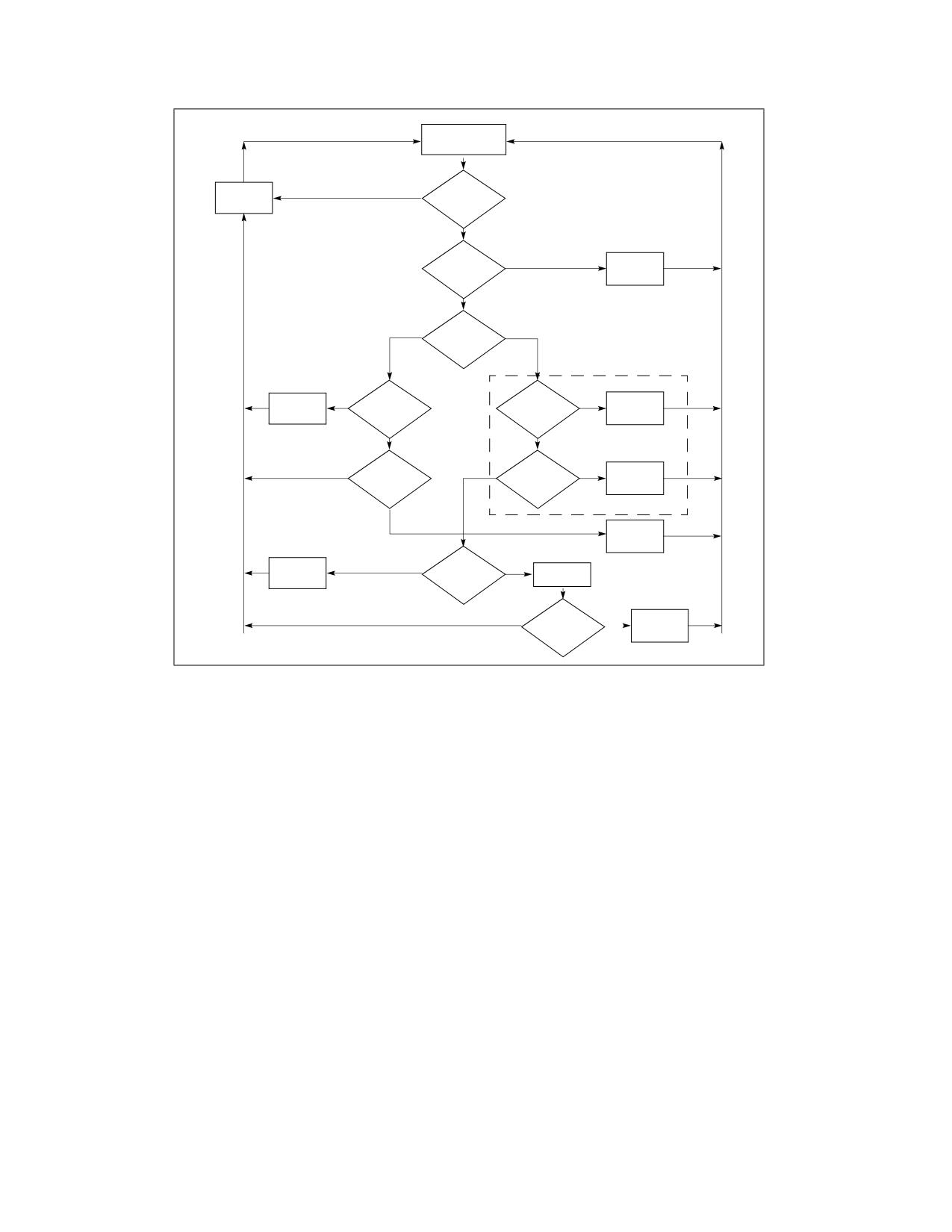
With the P6 family and Pentium processors, the local APIC handles the local interrupts, interrupt messages, and
IPIs it receives as follows (see Figure 11-17).
1. (IPIs only) The local APIC examines the IPI message to determines if it is the specified destination for the IPI
as described in Section 11.6.2, “Determining IPI Destination.” If it is the specified destination, it continues its
acceptance procedure; if it is not the destination, it discards the IPI message. When the message specifies
lowest-priority delivery mode, the local APIC will arbitrate with the other processors that were designated as
recipients of the IPI message (see Section 11.6.2.4, “Lowest Priority Delivery Mode”).
2. If the local APIC determines that it is the designated destination for the interrupt and if the interrupt request is
an NMI, SMI, INIT, ExtINT, or INIT-deassert interrupt, or one of the MP protocol IPI messages (BIPI, FIPI, and
SIPI), the interrupt is sent directly to the processor core for handling.
3. If the local APIC determines that it is the designated destination for the interrupt but the interrupt request is
not one of the interrupts given in step 2, the local APIC looks for an open slot in one of its two pending interrupt
queues contained in the IRR and ISR registers (see Figure 11-20). If a slot is available (see Section 11.8.4,
“Interrupt Acceptance for Fixed Interrupts”), places the interrupt in the slot. If a slot is not available, it rejects
the interrupt request and sends it back to the sender with a retry message.
4. When interrupts are pending in the IRR register, the local APIC dispatches them to the processor one at a time,
based on their priority and the current processor priority in the PPR (see Section 11.8.3.1, “Task and Processor
Priorities”).
5. When a fixed interrupt has been dispatched to the processor core for handling, the completion of the handler
routine is indicated with an instruction in the instruction handler code that writes to the end-of-interrupt (EOI)
Vol. 3A
11-27
ADVANCED PROGRAMMABLE INTERRUPT CONTROLLER (APIC)
Wait to Receive
Bus Message
Belong
Discard
No
to
Message
Destination?
Yes
Is it
Yes
NMI/SMI/INIT
Accept
/ExtINT?
Message
No
Lowest
Fixed
Priority
Delivery
P6 Family
Processor Specific
Set Status
No
Yes
Is Interrupt Slot
Am I
Accept
to Retry
Focus?
Available?
Message
Yes
No
Yes
Is Status a
No
Other
Yes
Discard
Retry?
Focus?
Message
No
Accept
Message
Set Status
No
Is Interrupt
Yes
Slot Avail-
Arbitrate
to Retry
able?
Am I Winner?
Accept
No
Yes
Message
Figure 11-17. Interrupt Acceptance Flow Chart for the Local APIC (P6 Family and Pentium Processors)
register in the local APIC (see Section 11.8.5, “Signaling Interrupt Servicing Completion”). The act of writing to
the EOI register causes the local APIC to delete the interrupt from its queue and (for level-triggered interrupts)
send a message on the bus indicating that the interrupt handling has been completed. (A write to the EOI
register must not be included in the handler routine for an NMI, SMI, INIT, ExtINT, or SIPI.)
The following sections describe the acceptance of interrupts and their handling by the local APIC and processor in
greater detail.
11.8.3 Interrupt, Task, and Processor Priority
Each interrupt delivered to the processor through the local APIC has a priority based on its vector number. The local
APIC uses this priority to determine when to service the interrupt relative to the other activities of the processor,
including the servicing of other interrupts.
Each interrupt vector is an 8-bit value. The interrupt-priority class is the value of bits 7:4 of the interrupt vector.
The lowest interrupt-priority class is 1 and the highest is 15; interrupts with vectors in the range 0-15 (with inter-
rupt-priority class 0) are illegal and are never delivered. Because vectors 0-31 are reserved for dedicated uses by
the Intel 64 and IA-32 architectures, software should configure interrupt vectors to use interrupt-priority classes in
the range 2-15.
Each interrupt-priority class encompasses 16 vectors. The relative priority of interrupts within an interrupt-priority
class is determined by the value of bits 3:0 of the vector number. The higher the value of those bits, the higher the
11-28
Vol. 3A
ADVANCED PROGRAMMABLE INTERRUPT CONTROLLER (APIC)
priority within that interrupt-priority class. Thus, each interrupt vector comprises two parts, with the high 4 bits
indicating its interrupt-priority class and the low 4 bits indicating its ranking within the interrupt-priority class.
11.8.3.1 Task and Processor Priorities
The local APIC also defines a task priority and a processor priority that determine the order in which interrupts
are handled. The task-priority class is the value of bits 7:4 of the task-priority register (TPR), which can be
written by software (TPR is a read/write register); see Figure 11-18.
31
87
4 3
0
Reserved
Task-Priority Class
Address: FEE0 0080H
Task-Priority Sub-Class
Value after reset: 0H
Figure 11-18. Task-Priority Register (TPR)
NOTE
In this discussion, the term “task” refers to a software defined task, process, thread, program, or
routine that is dispatched to run on the processor by the operating system. It does not refer to an
IA-32 architecture defined task as described in Chapter 8, “Task Management.”
The task priority allows software to set a priority threshold for interrupting the processor. This mechanism enables
the operating system to temporarily block low priority interrupts from disturbing high-priority work that the
processor is doing. The ability to block such interrupts using task priority results from the way that the TPR controls
the value of the processor-priority register (PPR).1
The processor-priority class is a value in the range 0-15 that is maintained in bits 7:4 of the processor-priority
register (PPR); see Figure 11-19. The PPR is a read-only register. The processor-priority class represents the
current priority at which the processor is executing.
31
87
4 3
0
Reserved
Processor-Priority Class
Processor-Priority Sub-Class
Address: FEE0 00A0H
Value after reset: 0H
Figure 11-19. Processor-Priority Register (PPR)
The value of the PPR is based on the value of TPR and the value ISRV; ISRV is the vector number of the highest
priority bit that is set in the ISR or 00H if no bit is set in the ISR. (See Section 11.8.4 for more details on the ISR.)
The value of PPR is determined as follows:
• PPR[7:4] (the processor-priority class) the maximum of TPR[7:4] (the task- priority class) and ISRV[7:4] (the
priority of the highest priority interrupt in service).
• PPR[3:0] (the processor-priority sub-class) is determined as follows:
- If TPR[7:4] > ISRV[7:4], PPR[3:0] is TPR[3:0] (the task-priority sub-class).
- If TPR[7:4] < ISRV[7:4], PPR[3:0] is 0.
- If TPR[7:4] = ISRV[7:4], PPR[3:0] may be either TPR[3:0] or 0. The actual behavior is model-specific.
1. The TPR also determines the arbitration priority of the local processor; see Section 11.6.2.4, “Lowest Priority Delivery Mode.”
Vol. 3A
11-29
ADVANCED PROGRAMMABLE INTERRUPT CONTROLLER (APIC)
The processor-priority class determines the priority threshold for interrupting the processor. The processor will
deliver only those interrupts that have an interrupt-priority class higher than the processor-priority class in the
PPR. If the processor-priority class is 0, the PPR does not inhibit the delivery any interrupt; if it is 15, the processor
inhibits the delivery of all interrupts. (The processor-priority mechanism does not affect the delivery of interrupts
with the NMI, SMI, INIT, ExtINT, INIT-deassert, and start-up delivery modes.)
The processor does not use the processor-priority sub-class to determine which interrupts to deliver and which to
inhibit. (The processor uses the processor-priority sub-class only to satisfy reads of the PPR.)
11.8.4 Interrupt Acceptance for Fixed Interrupts
The local APIC queues the fixed interrupts that it accepts in one of two interrupt pending registers: the interrupt
request register (IRR) or in-service register (ISR). These two 256-bit read-only registers are shown in
Figure 11-20. The 256 bits in these registers represent the 256 possible vectors; vectors 0 through 15 are reserved
by the APIC (see also: Section 11.5.2, “Valid Interrupt Vectors”).
NOTE
All interrupts with an NMI, SMI, INIT, ExtINT, start-up, or INIT-deassert delivery mode bypass the
IRR and ISR registers and are sent directly to the processor core for servicing.
255
16 15
0
Reserved
IRR
Reserved
ISR
Reserved
TMR
Addresses: IRR FEE0 0200H - FEE0 0270H
ISR FEE0 0100H - FEE0 0170H
TMR FEE0 0180H - FEE0 01F0H
Value after reset: 0H
Figure 11-20. IRR, ISR, and TMR Registers
The IRR contains the active interrupt requests that have been accepted, but not yet dispatched to the processor for
servicing. When the local APIC accepts an interrupt, it sets the bit in the IRR that corresponds the vector of the
accepted interrupt. When the processor core is ready to handle the next interrupt, the local APIC clears the highest
priority IRR bit that is set and sets the corresponding ISR bit. The vector for the highest priority bit set in the ISR is
then dispatched to the processor core for servicing.
While the processor is servicing the highest priority interrupt, the local APIC can send additional fixed interrupts by
setting bits in the IRR. When the interrupt service routine issues a write to the EOI register (see Section 11.8.5,
“Signaling Interrupt Servicing Completion”), the local APIC responds by clearing the highest priority ISR bit that is
set. It then repeats the process of clearing the highest priority bit in the IRR and setting the corresponding bit in
the ISR. The processor core then begins executing the service routing for the highest priority bit set in the ISR.
If more than one interrupt is generated with the same vector number, the local APIC can set the bit for the vector
both in the IRR and the ISR. This means that for the Pentium 4 and Intel Xeon processors, the IRR and ISR can
queue two interrupts for each interrupt vector: one in the IRR and one in the ISR. Any additional interrupts issued
for the same interrupt vector are collapsed into the single bit in the IRR.
For the P6 family and Pentium processors, the IRR and ISR registers can queue no more than two interrupts per
interrupt vector and will reject other interrupts that are received within the same vector.
If the local APIC receives an interrupt with an interrupt-priority class higher than that of the interrupt currently in
service, and interrupts are enabled in the processor core, the local APIC dispatches the higher priority interrupt to
the processor immediately (without waiting for a write to the EOI register). The currently executing interrupt
handler is then interrupted so the higher-priority interrupt can be handled. When the handling of the higher-priority
interrupt has been completed, the servicing of the interrupted interrupt is resumed.
11-30
Vol. 3A
ADVANCED PROGRAMMABLE INTERRUPT CONTROLLER (APIC)
The trigger mode register (TMR) indicates the trigger mode of the interrupt (see Figure 11-20). Upon acceptance
of an interrupt into the IRR, the corresponding TMR bit is cleared for edge-triggered interrupts and set for level-
triggered interrupts. If a TMR bit is set when an EOI cycle for its corresponding interrupt vector is generated, an
EOI message is sent to all I/O APICs.
11.8.5 Signaling Interrupt Servicing Completion
For all interrupts except those delivered with the NMI, SMI, INIT, ExtINT, the start-up, or INIT-Deassert delivery
mode, the interrupt handler must include a write to the end-of-interrupt (EOI) register (see Figure 11-21). This
write must occur at the end of the handler routine, sometime before the IRET instruction. This action indicates that
the servicing of the current interrupt is complete and the local APIC can issue the next interrupt from the ISR.
31
0
Address: 0FEE0 00B0H
Value after reset: 0H
Figure 11-21. EOI Register
Upon receiving an EOI, the APIC clears the highest priority bit in the ISR and dispatches the next highest priority
interrupt to the processor. If the terminated interrupt was a level-triggered interrupt, the local APIC also sends an
end-of-interrupt message to all I/O APICs.
System software may prefer to direct EOIs to specific I/O APICs rather than having the local APIC send end-of-
interrupt messages to all I/O APICs.
Software can inhibit the broadcast of EOI message by setting bit 12 of the Spurious Interrupt Vector Register (see
Section 11.9). If this bit is set, a broadcast EOI is not generated on an EOI cycle even if the associated TMR bit indi-
cates that the current interrupt was level-triggered. The default value for the bit is 0, indicating that EOI broadcasts
are performed.
Bit 12 of the Spurious Interrupt Vector Register is reserved to 0 if the processor does not support suppression of
EOI broadcasts. Support for EOI-broadcast suppression is reported in bit 24 in the Local APIC Version Register (see
Section 11.4.8); the feature is supported if that bit is set to 1. When supported, the feature is available in both
xAPIC mode and x2APIC mode.
System software desiring to perform directed EOIs for level-triggered interrupts should set bit 12 of the Spurious
Interrupt Vector Register and follow each the EOI to the local xAPIC for a level triggered interrupt with a directed
EOI to the I/O APIC generating the interrupt (this is done by writing to the I/O APIC’s EOI register). System soft-
ware performing directed EOIs must retain a mapping associating level-triggered interrupts with the I/O APICs in
the system.
11.8.6 Task Priority in IA-32e Mode
In IA-32e mode, operating systems can manage the 16 interrupt-priority classes (see Section 11.8.3, “Interrupt,
Task, and Processor Priority”) explicitly using the task priority register (TPR). Operating systems can use the TPR
to temporarily block specific (low-priority) interrupts from interrupting a high-priority task. This is done by loading
TPR with a value in which the task-priority class corresponds to the highest interrupt-priority class that is to be
blocked. For example:
• Loading the TPR with a task-priority class of 8 (01000B) blocks all interrupts with an interrupt-priority class of
8 or less while allowing all interrupts with an interrupt-priority class of 9 or more to be recognized.
• Loading the TPR with a task-priority class of 0 enables all external interrupts.
• Loading the TPR with a task-priority class of 0FH (01111B) disables all external interrupts.
The TPR (shown in Figure 11-18) is cleared to 0 on reset. In 64-bit mode, software can read and write the TPR
using an alternate interface, MOV CR8 instruction. The new task-priority class is established when the MOV CR8
Vol. 3A
11-31
ADVANCED PROGRAMMABLE INTERRUPT CONTROLLER (APIC)
instruction completes execution. Software does not need to force serialization after loading the TPR using MOV
CR8.
Use of the MOV CRn instruction requires a privilege level of 0. Programs running at privilege level greater than 0
cannot read or write the TPR. An attempt to do so causes a general-protection exception. The TPR is abstracted
from the interrupt controller (IC), which prioritizes and manages external interrupt delivery to the processor. The
IC can be an external device, such as an APIC or 8259. Typically, the IC provides a priority mechanism similar or
identical to the TPR. The IC, however, is considered implementation-dependent with the under-lying priority mech-
anisms subject to change. CR8, by contrast, is part of the Intel 64 architecture. Software can depend on this defi-
nition remaining unchanged.
Figure 11-22 shows the layout of CR8; only the low four bits are used. The remaining 60 bits are reserved and must
be written with zeros. Failure to do this causes a general-protection exception.
63
4
3
0
Reserved
Value after reset: 0H
Figure 11-22. CR8 Register
11.8.6.1 Interaction of Task Priorities between CR8 and APIC
The first implementation of Intel 64 architecture includes a local advanced programmable interrupt controller
(APIC) that is similar to the APIC used with previous IA-32 processors. Some aspects of the local APIC affect the
operation of the architecturally defined task priority register and the programming interface using CR8.
Notable CR8 and APIC interactions are:
• The processor powers up with the local APIC enabled.
• The APIC must be enabled for CR8 to function as the TPR. Writes to CR8 are reflected into the APIC Task Priority
Register.
• APIC.TPR[bits 7:4] = CR8[bits 3:0], APIC.TPR[bits 3:0] = 0. A read of CR8 returns a 64-bit value which is the
value of TPR[bits 7:4], zero extended to 64 bits.
There are no ordering mechanisms between direct updates of the APIC.TPR and CR8. Operating software should
implement either direct APIC TPR updates or CR8 style TPR updates but not mix them. Software can use a serial-
izing instruction (for example, CPUID) to serialize updates between MOV CR8 and stores to the APIC.
11.9
SPURIOUS INTERRUPT
A special situation may occur when a processor raises its task priority to be greater than or equal to the level of the
interrupt for which the processor INTR signal is currently being asserted. If at the time the INTA cycle is issued, the
interrupt that was to be dispensed has become masked (programmed by software), the local APIC will deliver a
spurious-interrupt vector. Dispensing the spurious-interrupt vector does not affect the ISR, so the handler for this
vector should return without an EOI.
The vector number for the spurious-interrupt vector is specified in the spurious-interrupt vector register (see
Figure 11-23). The functions of the fields in this register are as follows:
Spurious Vector Determines the vector number to be delivered to the processor when the local APIC generates
a spurious vector.
(Pentium 4 and Intel Xeon processors.) Bits 0 through 7 of the this field are programmable by
software.
(P6 family and Pentium processors). Bits 4 through 7 of the this field are programmable by
software, and bits 0 through 3 are hardwired to logical ones. Software writes to bits 0 through
3 have no effect.
11-32
Vol. 3A
ADVANCED PROGRAMMABLE INTERRUPT CONTROLLER (APIC)
APIC Software Enable/Disable
Allows software to temporarily enable (1) or disable (0) the local APIC (see Section 11.4.3,
“Enabling or Disabling the Local APIC”).
Focus Processor Checking
Determines if focus processor checking is enabled (0) or disabled (1) when using the lowest-
priority delivery mode. In Pentium 4 and Intel Xeon processors, this bit is reserved and should
be cleared to 0.
Suppress EOI Broadcasts
Determines whether an EOI for a level-triggered interrupt causes EOI messages to be broad-
cast to the I/O APICs (0) or not (1). See Section 11.8.5. The default value for this bit is 0, indi-
cating that EOI broadcasts are performed. This bit is reserved to 0 if the processor does not
support EOI-broadcast suppression.
NOTE
Do not program an LVT or IOAPIC RTE with a spurious vector even if you set the mask bit. A
spurious vector ISR does not do an EOI. If for some reason an interrupt is generated by an LVT or
RTE entry, the bit in the in-service register will be left set for the spurious vector. This will mask all
interrupts at the same or lower priority
31
121110
9
8
7
0
EOI-Broadcast Suppression1
0: Disabled
1: Enabled
Focus Processor Checking2
0: Enabled
1: Disabled
APIC Software Enable/Disable
0: APIC Disabled
1: APIC Enabled
Spurious Vector3
Address: FEE0 00F0H
Value after reset: 0000 00FFH
1. Not supported on all processors. See bit 24 of Local APIC Version Register.
2. Not supported in Pentium 4 and Intel Xeon processors.
3. For the P6 family and Pentium processors, bits 0 through 3 are always 1.
Figure 11-23. Spurious-Interrupt Vector Register (SVR)
11.10 APIC BUS MESSAGE PASSING MECHANISM AND PROTOCOL (P6 FAMILY,
PENTIUM PROCESSORS)
The Pentium 4 and Intel Xeon processors pass messages among the local and I/O APICs on the system bus, using
the system bus message passing mechanism and protocol.
The P6 family and Pentium processors, pass messages among the local and I/O APICs on the serial APIC bus, as
follows. Because only one message can be sent at a time on the APIC bus, the I/O APIC and local APICs employ a
“rotating priority” arbitration protocol to gain permission to send a message on the APIC bus. One or more APICs
may start sending their messages simultaneously. At the beginning of every message, each APIC presents the type
of the message it is sending and its current arbitration priority on the APIC bus. This information is used for arbi-
tration. After each arbitration cycle (within an arbitration round), only the potential winners keep driving the bus.
Vol. 3A
11-33
ADVANCED PROGRAMMABLE INTERRUPT CONTROLLER (APIC)
By the time all arbitration cycles are completed, there will be only one APIC left driving the bus. Once a winner is
selected, it is granted exclusive use of the bus, and will continue driving the bus to send its actual message.
After each successfully transmitted message, all APICs increase their arbitration priority by 1. The previous winner
(that is, the one that has just successfully transmitted its message) assumes a priority of 0 (lowest). An agent
whose arbitration priority was 15 (highest) during arbitration, but did not send a message, adopts the previous
winner’s arbitration priority, incremented by 1.
Note that the arbitration protocol described above is slightly different if one of the APICs issues a special End-Of-
Interrupt (EOI). This high-priority message is granted the bus regardless of its sender’s arbitration priority, unless
more than one APIC issues an EOI message simultaneously. In the latter case, the APICs sending the EOI
messages arbitrate using their arbitration priorities.
If the APICs are set up to use “lowest priority” arbitration (see Section 11.6.2.4, “Lowest Priority Delivery Mode”)
and multiple APICs are currently executing at the lowest priority (the value in the APR register), the arbitration
priorities (unique values in the Arb ID register) are used to break ties. All 8 bits of the APR are used for the lowest
priority arbitration.
11.10.1 Bus Message Formats
See Section 11.13, “APIC Bus Message Formats,” for a description of bus message formats used to transmit
messages on the serial APIC bus.
11.11 MESSAGE SIGNALLED INTERRUPTS
The PCI Local Bus Specification, Rev 2.2 (www.pcisig.com) introduces the concept of message signalled interrupts.
As the specification indicates:
“Message signalled interrupts (MSI) is an optional feature that enables PCI devices to request
service by writing a system-specified message to a system-specified address (PCI DWORD memory
write transaction). The transaction address specifies the message destination while the transaction
data specifies the message. System software is expected to initialize the message destination and
message during device configuration, allocating one or more non-shared messages to each MSI
capable function.”
The capabilities mechanism provided by the PCI Local Bus Specification is used to identify and configure MSI
capable PCI devices. Among other fields, this structure contains a Message Data Register and a Message Address
Register. To request service, the PCI device function writes the contents of the Message Data Register to the
address contained in the Message Address Register (and the Message Upper Address register for 64-bit message
addresses).
Section 11.11.1 and Section 11.11.2 provide layout details for the Message Address Register and the Message Data
Register. The operation issued by the device is a PCI write command to the Message Address Register with the
Message Data Register contents. The operation follows semantic rules as defined for PCI write operations and is a
DWORD operation.
11.11.1 Message Address Register Format
The format of the Message Address Register (lower 32-bits) is shown in Figure 11-24.
31
20
19
12
11
4
3
2
1
0
0FEEH
Destination ID
Reserved
RH
DM
XX
Figure 11-24. Layout of the MSI Message Address Register
11-34
Vol. 3A
ADVANCED PROGRAMMABLE INTERRUPT CONTROLLER (APIC)
Fields in the Message Address Register are as follows:
1.
Bits 31-20 - These bits contain a fixed value for interrupt messages (0FEEH). This value locates interrupts at
the 1-MByte area with a base address of 4G - 18M. All accesses to this region are directed as interrupt
messages. Care must to be taken to ensure that no other device claims the region as I/O space.
2.
Destination ID - This field contains an 8-bit destination ID. It identifies the message’s target processor(s).
The destination ID corresponds to bits 63:56 of the I/O APIC Redirection Table Entry if the IOAPIC is used to
dispatch the interrupt to the processor(s).
3.
Redirection hint indication (RH) - When this bit is set, the message is directed to the processor with the
lowest interrupt priority among processors that can receive the interrupt.
• When RH is 0, the interrupt is directed to the processor listed in the Destination ID field.
• When RH is 1 and the physical destination mode is used, the Destination ID field must not be set to FFH;
it must point to a processor that is present and enabled to receive the interrupt.
• When RH is 1 and the logical destination mode is active in a system using a flat addressing model, the
Destination ID field must be set so that bits set to 1 identify processors that are present and enabled to
receive the interrupt.
• If RH is set to 1 and the logical destination mode is active in a system using cluster addressing model,
then Destination ID field must not be set to FFH; the processors identified with this field must be
present and enabled to receive the interrupt.
4.
Destination mode (DM) - This bit indicates whether the Destination ID field should be interpreted as logical
or physical APIC ID for delivery of the lowest priority interrupt.
• If RH is 1 and DM is 0, the Destination ID field is in physical destination mode and only the processor in
the system that has the matching APIC ID is considered for delivery of that interrupt (this means no re-
direction).
• If RH is 1 and DM is 1, the Destination ID Field is interpreted as in logical destination mode and the
redirection is limited to only those processors that are part of the logical group of processors based on
the processor’s logical APIC ID and the Destination ID field in the message. The logical group of
processors consists of those identified by matching the 8-bit Destination ID with the logical destination
identified by the Destination Format Register and the Logical Destination Register in each local APIC.
The details are similar to those described in Section 11.6.2, “Determining IPI Destination.”
• If RH is 0, then the DM bit is ignored and the message is sent ahead independent of whether the
physical or logical destination mode is used.
11.11.2 Message Data Register Format
The layout of the Message Data Register is shown in Figure 11-25.
Reserved fields are not assumed to be any value. Software must preserve their contents on writes. Other fields in
the Message Data Register are described below.
1. Vector - This 8-bit field contains the interrupt vector associated with the message. Values range from 010H
to 0FEH. Software must guarantee that the field is not programmed with vector 00H to 0FH.
2. Delivery Mode - This 3-bit field specifies how the interrupt receipt is handled. Delivery Modes operate only in
conjunction with specified Trigger Modes. Correct Trigger Modes must be guaranteed by software. Restrictions
are indicated below:
a.
000B (Fixed Mode) - Deliver the signal to all the agents listed in the destination. The Trigger Mode for
fixed delivery mode can be edge or level.
b.
001B (Lowest Priority) - Deliver the signal to the agent that is executing at the lowest priority of all
agents listed in the destination field. The trigger mode can be edge or level.
c.
010B (System Management Interrupt or SMI) - The delivery mode is edge only. For systems that rely
on SMI semantics, the vector field is ignored but must be programmed to all zeroes for future compatibility.
Vol. 3A
11-35
ADVANCED PROGRAMMABLE INTERRUPT CONTROLLER (APIC)
63
32
Reserved
31
16
15
14
13
11
10
8
7
0
Reserved
Reserved
Vector
Trigger Mode
Delivery Mode
0 - Edge
000 - Fixed
1 - Level
001 - Lowest Priority
010 - SMI
011 - Reserved
Level for Trigger Mode = 0
100 - NMI
X - Don’t care
101 - INIT
Level for Trigger Mode = 1
110 - Reserved
0 - Deassert
111 - ExtINT
1 - Assert
Figure 11-25. Layout of the MSI Message Data Register
d.
100B (NMI) - Deliver the signal to all the agents listed in the destination field. The vector information is
ignored. NMI is an edge triggered interrupt regardless of the Trigger Mode Setting.
e.
101B (INIT) - Deliver this signal to all the agents listed in the destination field. The vector information is
ignored. INIT is an edge triggered interrupt regardless of the Trigger Mode Setting.
f.
111B (ExtINT) - Deliver the signal to the INTR signal of all agents in the destination field (as an interrupt
that originated from an 8259A compatible interrupt controller). The vector is supplied by the INTA cycle
issued by the activation of the ExtINT. ExtINT is an edge triggered interrupt.
3. Level - Edge triggered interrupt messages are always interpreted as assert messages. For edge triggered
interrupts this field is not used. For level triggered interrupts, this bit reflects the state of the interrupt input.
4. Trigger Mode - This field indicates the signal type that will trigger a message.
a.
0 - Indicates edge sensitive.
b.
1 - Indicates level sensitive.
11.12 EXTENDED XAPIC (X2APIC)
The x2APIC architecture extends the xAPIC architecture (described in Section 11.4) in a backward compatible
manner and provides forward extendability for future Intel platform innovations. Specifically, the x2APIC architec-
ture does the following.
• Retains all key elements of compatibility to the xAPIC architecture.
- Delivery modes.
- Interrupt and processor priorities.
- Interrupt sources.
- Interrupt destination types.
• Provides extensions to scale processor addressability for both the logical and physical destination modes.
11-36
Vol. 3A
ADVANCED PROGRAMMABLE INTERRUPT CONTROLLER (APIC)
• Adds new features to enhance performance of interrupt delivery.
• Reduces complexity of logical destination mode interrupt delivery on link based platform architectures.
• Uses MSR programming interface to access APIC registers in x2APIC mode instead of memory-mapped
interfaces. Memory-mapped interface is supported when operating in xAPIC mode.
11.12.1 Detecting and Enabling x2APIC Mode
Processor support for x2APIC mode can be detected by executing CPUID with EAX=1 and then checking ECX, bit
21 ECX. If CPUID.(EAX=1):ECX.21 is set , the processor supports the x2APIC capability and can be placed into the
x2APIC mode.
System software can place the local APIC in the x2APIC mode by setting the x2APIC mode enable bit (bit 10) in the
IA32_APIC_BASE MSR at MSR address 01BH. The layout for the IA32_APIC_BASE MSR is shown in Figure 11-26.
63
36 35
12 11109
8
7
0
Reserved
APIC Base
APIC Base-Base physical address
EN-xAPIC global enable/disable
EXTD-Enable x2APIC mode
BSP-Processor is BSP
Reserved
Figure 11-26. IA32_APIC_BASE MSR Supporting x2APIC
Table 11-5, “x2APIC operating mode configurations” describe the possible combinations of the enable bit (EN - bit
11) and the extended mode bit (EXTD - bit 10) in the IA32_APIC_BASE MSR.
Table 11-5. x2APIC Operating Mode Configurations
xAPIC global enable
x2APIC enable
(IA32_APIC_BASE[11])
(IA32_APIC_BASE[10])
Description
0
0
local APIC is disabled
0
1
Invalid
1
0
local APIC is enabled in xAPIC mode
1
1
local APIC is enabled in x2APIC mode
Once the local APIC has been switched to x2APIC mode (EN = 1, EXTD = 1), switching back to xAPIC mode would
require system software to disable the local APIC unit. Specifically, attempting to write a value to the
IA32_APIC_BASE MSR that has (EN= 1, EXTD = 0) when the local APIC is enabled and in x2APIC mode causes a
general-protection exception. Once bit 10 in IA32_APIC_BASE MSR is set, the only way to leave x2APIC mode
using IA32_APIC_BASE would require a WRMSR to set both bit 11 and bit 10 to zero. Section 11.12.5, “x2APIC
State Transitions,” provides a detailed state diagram for the state transitions allowed for the local APIC.
11.12.1.1 Instructions to Access APIC Registers
In x2APIC mode, system software uses RDMSR and WRMSR to access the APIC registers. The MSR addresses for
accessing the x2APIC registers are architecturally defined and specified in Section 11.12.1.2, “x2APIC Register
Address Space.” Executing the RDMSR instruction with the APIC register address specified in ECX returns the
content of bits 0 through 31 of the APIC registers in EAX. Bits 32 through 63 are returned in register EDX - these
bits are reserved if the APIC register being read is a 32-bit register. Similarly executing the WRMSR instruction with
the APIC register address in ECX, writes bits 0 to 31 of register EAX to bits 0 to 31 of the specified APIC register. If
the register is a 64-bit register then bits 0 to 31 of register EDX are written to bits 32 to 63 of the APIC register. The
Vol. 3A
11-37

ADVANCED PROGRAMMABLE INTERRUPT CONTROLLER (APIC)
Interrupt Command Register is the only APIC register that is implemented as a 64-bit MSR. The semantics of
handling reserved bits are defined in Section 11.12.1.3, “Reserved Bit Checking.”
11.12.1.2 x2APIC Register Address Space
The MSR address range 800H through 8FFH is architecturally reserved and dedicated for accessing APIC registers
in x2APIC mode. Table 11-6 lists the APIC registers that are available in x2APIC mode. When appropriate, the table
also gives the offset at which each register is available on the page referenced by IA32_APIC_BASE[35:12] in
xAPIC mode.
There is a one-to-one mapping between the x2APIC MSRs and the legacy xAPIC register offsets with the following
exceptions:
• The Destination Format Register (DFR): The DFR, supported at offset 0E0H in xAPIC mode, is not supported in
x2APIC mode. There is no MSR with address 80EH.
• The Interrupt Command Register (ICR): The two 32-bit registers in xAPIC mode (at offsets 300H and 310H) are
merged into a single 64-bit MSR in x2APIC mode (with MSR address 830H). There is no MSR with address
831H.
• The SELF IPI register. This register is available only in x2APIC mode at address 83FH. In xAPIC mode, there is
no register defined at offset 3F0H.
MSR addresses in the range 800H-8FFH that are not listed in Table 11-6 (including 80EH and 831H) are reserved.
Executions of RDMSR and WRMSR that attempt to access such addresses cause general-protection exceptions.
The MSR address space is compressed to allow for future growth. Every 32 bit register on a 128-bit boundary in the
legacy MMIO space is mapped to a single MSR in the local x2APIC MSR address space. The upper 32-bits of all
x2APIC MSRs (except for the ICR) are reserved.
Table 11-6. Local APIC Register Address Map Supported by x2APIC
MSR Address
MMIO Offset
MSR R/W
Register Name
Comments
(x2APIC mode)
(xAPIC mode)
Semantics
802H
020H
Local APIC ID register
Read-only1
See Section 11.12.5.1 for initial
values.
803H
030H
Local APIC Version register
Read-only
Same version used in xAPIC mode
and x2APIC mode.
808H
080H
Task Priority Register (TPR)
Read/write
Bits 31:8 are reserved.2
80AH
0A0H
Processor Priority Register
Read-only
(PPR)
80BH
0B0H
EOI register
Write-only3
WRMSR of a non-zero value causes
#GP(0).
80DH
0D0H
Logical Destination Register
Read-only
Read/write in xAPIC mode.
(LDR)
80FH
0F0H
Spurious Interrupt Vector
Read/write
See Section 11.9 for reserved bits.
Register (SVR)
810H
100H
In-Service Register (ISR); bits
Read-only
31:0
811H
110H
ISR bits 63:32
Read-only
812H
120H
ISR bits 95:64
Read-only
813H
130H
ISR bits 127:96
Read-only
814H
140H
ISR bits 159:128
Read-only
815H
150H
ISR bits 191:160
Read-only
816H
160H
ISR bits 223:192
Read-only
11-38
Vol. 3A

ADVANCED PROGRAMMABLE INTERRUPT CONTROLLER (APIC)
Table 11-6. Local APIC Register Address Map Supported by x2APIC (Contd.)
MSR Address
MMIO Offset
MSR R/W
Register Name
Comments
(x2APIC mode)
(xAPIC mode)
Semantics
817H
170H
ISR bits 255:224
Read-only
818H
180H
Trigger Mode Register (TMR);
Read-only
bits 31:0
819H
190H
TMR bits 63:32
Read-only
81AH
1A0H
TMR bits 95:64
Read-only
81BH
1B0H
TMR bits 127:96
Read-only
81CH
1C0H
TMR bits 159:128
Read-only
81DH
1D0H
TMR bits 191:160
Read-only
81EH
1E0H
TMR bits 223:192
Read-only
81FH
1F0H
TMR bits 255:224
Read-only
820H
200H
Interrupt Request Register
Read-only
(IRR); bits 31:0
821H
210H
IRR bits 63:32
Read-only
822H
220H
IRR bits 95:64
Read-only
823H
230H
IRR bits 127:96
Read-only
824H
240H
IRR bits 159:128
Read-only
825H
250H
IRR bits 191:160
Read-only
826H
260H
IRR bits 223:192
Read-only
827H
270H
IRR bits 255:224
Read-only
828H
280H
Error Status Register (ESR)
Read/write
WRMSR of a non-zero value causes
#GP(0). See Section 11.5.3.
82FH
2F0H
LVT CMCI register
Read/write
See Figure 11-8 for reserved bits.
830H4
300H and 310H
Interrupt Command Register
Read/write
See Figure 11-28 for reserved bits
(ICR)
832H
320H
LVT Timer register
Read/write
See Figure 11-8 for reserved bits.
833H
330H
LVT Thermal Sensor register
Read/write
See Figure 11-8 for reserved bits.
834H
340H
LVT Performance Monitoring
Read/write
See Figure 11-8 for reserved bits.
register
835H
350H
LVT LINT0 register
Read/write
See Figure 11-8 for reserved bits.
836H
360H
LVT LINT1 register
Read/write
See Figure 11-8 for reserved bits.
837H
370H
LVT Error register
Read/write
See Figure 11-8 for reserved bits.
838H
380H
Initial Count register (for
Read/write
Timer)
839H
390H
Current Count register (for
Read-only
Timer)
83EH
3E0H
Divide Configuration Register
Read/write
See Figure 11-10 for reserved bits.
(DCR; for Timer)
83FH
Not available
SELF IPI5
Write-only
Available only in x2APIC mode.
NOTES:
1. WRMSR causes #GP(0) for read-only registers.
Vol. 3A
11-39
ADVANCED PROGRAMMABLE INTERRUPT CONTROLLER (APIC)
2. WRMSR causes #GP(0) for attempts to set a reserved bit to 1 in a read/write register (including bits 63:32 of each register).
3. RDMSR causes #GP(0) for write-only registers.
4. MSR 831H is reserved; read/write operations cause general-protection exceptions. The contents of the APIC register at MMIO offset
310H are accessible in x2APIC mode through the MSR at address 830H.
5. SELF IPI register is supported only in x2APIC mode.
11.12.1.3 Reserved Bit Checking
Section 11.12.1.2 and Table 11-6 specifies the reserved bit definitions for the APIC registers in x2APIC mode. Non-
zero writes (by WRMSR instruction) to reserved bits to these registers will raise a general protection fault exception
while reads return zeros (RsvdZ semantics).
In x2APIC mode, the local APIC ID register is increased to 32 bits wide. This enables 232-1 processors to be
addressable in physical destination mode. This 32-bit value is referred to as “x2APIC ID”. A processor implementa-
tion may choose to support less than 32 bits in its hardware. System software should be agnostic to the actual
number of bits that are implemented. All non-implemented bits will return zeros on reads by software.
The APIC ID value of FFFF_FFFFH and the highest value corresponding to the implemented bit-width of the local
APIC ID register in the system are reserved and cannot be assigned to any logical processor.
In x2APIC mode, the local APIC ID register is a read-only register to system software and will be initialized by hard-
ware. It is accessed via the RDMSR instruction reading the MSR at address 0802H.
Each logical processor in the system (including clusters with a communication fabric) must be configured with an
unique x2APIC ID to avoid collisions of x2APIC IDs. On DP and high-end MP processors targeted to specific market
segments and depending on the system configuration, it is possible that logical processors in different and “un-
connected” clusters power up initialized with overlapping x2APIC IDs. In these configurations, a model-specific
means may be provided in those product segments to enable BIOS and/or platform firmware to re-configure the
x2APIC IDs in some clusters to provide for unique and non-overlapping system wide IDs before configuring the
disconnected components into a single system.
11.12.2 x2APIC Register Availability
The local APIC registers can be accessed via the MSR interface only when the local APIC has been switched to the
x2APIC mode as described in Section 11.12.1. Accessing any APIC register in the MSR address range 0800H
through 08FFH via RDMSR or WRMSR when the local APIC is not in x2APIC mode causes a general-protection
exception. In x2APIC mode, the memory mapped interface is not available and any access to the MMIO interface
will behave similar to that of a legacy xAPIC in globally disabled state. Table 11-7 provides the interactions between
the legacy & extended modes and the legacy and register interfaces.
Table 11-7. MSR/MMIO Interface of a Local x2APIC in Different Modes of Operation
MMIO Interface
MSR Interface
xAPIC mode
Available
General-protection exception
x2APIC mode
Behavior identical to xAPIC in globally disabled state
Available
11.12.3 MSR Access in x2APIC Mode
To allow for efficient access to the APIC registers in x2APIC mode, the serializing semantics of WRMSR are relaxed
when writing to the APIC registers. Thus, system software should not use “WRMSR to APIC registers in x2APIC
mode” as a serializing instruction. Read and write accesses to the APIC registers will occur in program order. A
WRMSR to an APIC register may complete before all preceding stores are globally visible; software can prevent this
by inserting a serializing instruction or the sequence MFENCE;LFENCE before the WRMSR.
The RDMSR instruction is not serializing and this behavior is unchanged when reading APIC registers in x2APIC
mode. System software accessing the APIC registers using the RDMSR instruction should not expect a serializing
behavior. (Note: The MMIO-based xAPIC interface is mapped by system software as an un-cached region. Conse-
quently, read/writes to the xAPIC-MMIO interface have serializing semantics in the xAPIC mode.)
11-40
Vol. 3A
ADVANCED PROGRAMMABLE INTERRUPT CONTROLLER (APIC)
11.12.4 VM-Exit Controls for MSRs and x2APIC Registers
The VMX architecture allows a VMM to specify lists of MSRs to be loaded or stored on VMX transitions using the
VMX-transition MSR areas (see VM-exit MSR-store address field, VM-exit MSR-load address field, and VM-entry
MSR-load address field in Intel® 64 and IA-32 Architectures Software Developer’s Manual, Volume 3C).
The X2APIC MSRs cannot to be loaded and stored on VMX transitions. A VMX transition fails if the VMM has speci-
fied that the transition should access any MSRs in the address range from 0000_0800H to 0000_08FFH (the range
used for accessing the X2APIC registers). Specifically, processing of an 128-bit entry in any of the VMX-transition
MSR areas fails if bits 31:0 of that entry (represented as ENTRY_LOW_DW) satisfies the expression:
“ENTRY_LOW_DW & FFFFF800H = 00000800H”. Such a failure causes an associated VM entry to fail (by reloading
host state) and causes an associated VM exit to lead to VMX abort.
11.12.5 x2APIC State Transitions
This section provides a detailed description of the x2APIC states of a local x2APIC unit, transitions between these
states as well as interactions of these states with INIT and reset.
11.12.5.1 x2APIC States
The valid states for a local x2APIC unit are listed in Table 11-5.
• APIC disabled: IA32_APIC_BASE[EN]=0 and IA32_APIC_BASE[EXTD]=0.
• xAPIC mode: IA32_APIC_BASE[EN]=1 and IA32_APIC_BASE[EXTD]=0.
• x2APIC mode: IA32_APIC_BASE[EN]=1 and IA32_APIC_BASE[EXTD]=1.
• Invalid: IA32_APIC_BASE[EN]=0 and IA32_APIC_BASE[EXTD]=1.
The state corresponding to EXTD=1 and EN=0 is not valid and it is not possible to get into this state. An execution
of WRMSR to the IA32_APIC_BASE_MSR that attempts a transition from a valid state to this invalid state causes a
general-protection exception. Figure 11-27 shows the comprehensive state transition diagram for a local x2APIC
unit.
On coming out of reset, the local APIC unit is enabled and is in the xAPIC mode: IA32_APIC_BASE[EN]=1 and
IA32_APIC_BASE[EXTD]=0. The APIC registers are initialized as follows.
• The local APIC ID is initialized by hardware with a 32 bit ID (x2APIC ID). The lowest 8 bits of the x2APIC ID are
the legacy local xAPIC ID, and are stored in the upper 8 bits of the APIC register for access in xAPIC mode.
• The following APIC registers are reset to all zeros for those fields that are defined in the xAPIC mode.
- IRR, ISR, TMR, ICR, LDR, TPR, Divide Configuration Register (See Section 11.4 through Section 11.6 for
details of individual APIC registers).
- Timer initial count and timer current count registers.
• The LVT registers are reset to 0s except for the mask bits; these are set to 1s.
• The local APIC version register is not affected.
• The Spurious Interrupt Vector Register is initialized to 000000FFH.
• The DFR (available only in xAPIC mode) is reset to all 1s.
• SELF IPI register is reset to zero.
Vol. 3A
11-41
ADVANCED PROGRAMMABLE INTERRUPT CONTROLLER (APIC)
Reset
Init
Disabled
Init
EN = 0
Illegal
EN =1
Extd = 0
Transition
Extd = 1
EN = 0
Illegal
xAPIC Mode
EN = 0
Extd = 0
Transition
Invalid
EN=1, Extd=0
State
Extd = 1
Illegal
Transition
EN = 0
Extd = 1
Extd = 0
Illegal
Reset
Transition
Extended
EN = 0
Mode
EN=1, Extd=1
Reset
Init
Figure 11-27. Local x2APIC State Transitions with IA32_APIC_BASE, INIT, and Reset
x2APIC After Reset
The valid transitions from the xAPIC mode state are:
• to the x2APIC mode by setting EXT to 1 (resulting EN=1, EXTD= 1). The physical x2APIC ID (see Figure 11-6)
is preserved across this transition and the logical x2APIC ID (see Figure 11-29) is initialized by hardware during
this transition as documented in Section 11.12.10.2. The state of the extended fields in other APIC registers,
which was not initialized at reset, is not architecturally defined across this transition and system software
should explicitly initialize those programmable APIC registers.
• to the disabled state by setting EN to 0 (resulting EN=0, EXTD= 0).
The result of an INIT in the xAPIC state places the APIC in the state with EN= 1, EXTD= 0. The state of the local
APIC ID register is preserved (the 8-bit xAPIC ID is in the upper 8 bits of the APIC ID register). All the other APIC
registers are initialized as a result of INIT.
A reset in this state places the APIC in the state with EN= 1, EXTD= 0. The state of the local APIC ID register is
initialized as described in Section 11.12.5.1. All the other APIC registers are initialized described in Section
11.12.5.1.
x2APIC Transitions From x2APIC Mode
From the x2APIC mode, the only valid x2APIC transition using IA32_APIC_BASE is to the state where the x2APIC
is disabled by setting EN to 0 and EXTD to 0. The x2APIC ID (32 bits) and the legacy local xAPIC ID (8 bits) are
preserved across this transition. A transition from the x2APIC mode to xAPIC mode is not valid, and the corre-
sponding WRMSR to the IA32_APIC_BASE MSR causes a general-protection exception.
A reset in this state places the x2APIC in xAPIC mode. All APIC registers (including the local APIC ID register) are
initialized as described in Section 11.12.5.1.
An INIT in this state keeps the x2APIC in the x2APIC mode. The state of the local APIC ID register is preserved (all
32 bits). However, all the other APIC registers are initialized as a result of the INIT transition.
11-42
Vol. 3A
ADVANCED PROGRAMMABLE INTERRUPT CONTROLLER (APIC)
x2APIC Transitions From Disabled Mode
From the disabled state, the only valid x2APIC transition using IA32_APIC_BASE is to the xAPIC mode (EN= 1,
EXTD = 0). Thus the only means to transition from x2APIC mode to xAPIC mode is a two-step process:
• first transition from x2APIC mode to local APIC disabled mode (EN= 0, EXTD = 0),
• followed by another transition from disabled mode to xAPIC mode (EN= 1, EXTD= 0).
Consequently, all the APIC register states in the x2APIC, except for the x2APIC ID (32 bits), are not preserved
across mode transitions.
A reset in the disabled state places the x2APIC in the xAPIC mode. All APIC registers (including the local APIC ID
register) are initialized as described in Section 11.12.5.1.
An INIT in the disabled state keeps the x2APIC in the disabled state.
State Changes From xAPIC Mode to x2APIC Mode
After APIC register states have been initialized by software in xAPIC mode, a transition from xAPIC mode to x2APIC
mode does not affect most of the APIC register states, except the following:
• The Logical Destination Register is not preserved.
• Any APIC ID value written to the memory-mapped local APIC ID register is not preserved.
• The high half of the Interrupt Command Register is not preserved.
11.12.6 Routing of Device Interrupts in x2APIC Mode
The x2APIC architecture is intended to work with all existing IOxAPIC units as well as all PCI and PCI Express
(PCIe) devices that support the capability for message-signaled interrupts (MSI). Support for x2APIC modifies only
the following:
• the local APIC units;
• the interconnects joining IOxAPIC units to the local APIC units; and
• the interconnects joining MSI-capable PCI and PCIe devices to the local APIC units.
No modifications are required to MSI-capable PCI and PCIe devices. Similarly, no modifications are required to
IOxAPIC units. This is made possible through use of the interrupt-remapping architecture specified in the Intel®
Virtualization Technology for Directed I/O Specification, Revision 1.3 and/or later versions, for the routing of inter-
rupts from MSI-capable devices to local APIC units operating in x2APIC mode.
11.12.7 Initialization by System Software
Routing of device interrupts to local APIC units operating in x2APIC mode requires use of the interrupt-remapping
architecture specified in the Intel® Virtualization Technology for Directed I/O Specification (Revision 1.3 and/or
later versions). Because of this, BIOS must enumerate support for and software must enable this interrupt remap-
ping with Extended Interrupt Mode Enabled before it enabling x2APIC mode in the local APIC units.
The ACPI interfaces for the x2APIC are described in Section 5.2, “ACPI System Description Tables,” of the Advanced
Configuration and Power Interface Specification, Revision 4.0a (http://www.acpi.info/spec.htm). The default
behavior for BIOS is to pass the control to the operating system with the local x2APICs in xAPIC mode if all APIC
IDs reported by CPUID.0BH:EDX are less than 255, and in x2APIC mode if there are any logical processor reporting
an APIC ID of 255 or greater.
11.12.8 CPUID Extensions And Topology Enumeration
For Intel 64 and IA-32 processors that support x2APIC, a value of 1 reported by CPUID.01H:ECX[21] indicates that
the processor supports x2APIC and the extended topology enumeration leaf (CPUID.0BH).
Vol. 3A
11-43
ADVANCED PROGRAMMABLE INTERRUPT CONTROLLER (APIC)
The extended topology enumeration leaf can be accessed by executing CPUID with EAX = 0BH. Processors that do
not support x2APIC may support CPUID leaf 0BH. Software can detect the availability of the extended topology
enumeration leaf (0BH) by performing two steps:
• Check maximum input value for basic CPUID information by executing CPUID with EAX= 0. If CPUID.0H:EAX is
greater than or equal or 11 (0BH), then proceed to next step
• Check CPUID.EAX=0BH, ECX=0H:EBX is non-zero.
If both of the above conditions are true, extended topology enumeration leaf is available. If available, the extended
topology enumeration leaf is the preferred mechanism for enumerating topology. The presence of CPUID leaf 0BH
in a processor does not guarantee support for x2APIC. If CPUID.EAX=0BH, ECX=0H:EBX returns zero and
maximum input value for basic CPUID information is greater than 0BH, then CPUID.0BH leaf is not supported on
that processor.
The extended topology enumeration leaf is intended to assist software with enumerating processor topology on
systems that requires 32-bit x2APIC IDs to address individual logical processors. Details of CPUID leaf 0BH can be
found in the reference pages of CPUID in Chapter 3 of Intel® 64 and IA-32 Architectures Software Developer’s
Manual, Volume 2A.
Processor topology enumeration algorithm for processors supporting the extended topology enumeration leaf of
CPUID and processors that do not support CPUID leaf 0BH are treated in Section 9.9.4, “Algorithm for Three-
Domain Mappings of APIC_ID.”
11.12.8.1 Consistency of APIC IDs and CPUID
The consistency of physical x2APIC ID in MSR 802H in x2APIC mode and the 32-bit value returned in
CPUID.0BH:EDX is facilitated by processor hardware.
CPUID.0BH:EDX will report the full 32 bit ID, in xAPIC and x2APIC mode. This allows BIOS to determine if a system
has processors with IDs exceeding the 8-bit initial APIC ID limit (CPUID.01H:EBX[31:24]). Initial APIC ID
(CPUID.01H:EBX[31:24]) is always equal to CPUID.0BH:EDX[7:0].
If the values of CPUID.0BH:EDX reported by all logical processors in a system are less than 255, BIOS can transfer
control to OS in xAPIC mode.
If the values of CPUID.0BH:EDX reported by some logical processors in a system are greater than or equal to 255,
BIOS must support two options to hand off to OS.
• If BIOS enables logical processors with x2APIC IDs greater than 255, then it should enable x2APIC in the Boot
Strap Processor (BSP) and all Application Processors (AP) before passing control to the OS. Applications
requiring processor topology information must use OS provided services based on x2APIC IDs or CPUID.0BH
leaf.
• If a BIOS transfers control to OS in xAPIC mode, then the BIOS must ensure that only logical processors with
CPUID.0BH.EDX value less than 255 are enabled. BIOS initialization on all logical processors with
CPUID.0B.EDX values greater than or equal to 255 must (a) disable APIC and execute CLI in each logical
processor, and (b) leave these logical processor in the lowest power state so that these processors do not
respond to INIT IPI during OS boot. The BSP and all the enabled logical processor operate in xAPIC mode after
BIOS passed control to OS. Application requiring processor topology information can use OS provided legacy
services based on 8-bit initial APIC IDs or legacy topology information from CPUID.01H and CPUID 04H leaves.
Even if the BIOS passes control in xAPIC mode, an OS can switch the processors to x2APIC mode later. BIOS
SMM handler should always read the APIC_BASE_MSR, determine the APIC mode and use the corresponding
access method.
11.12.9 ICR Operation in x2APIC Mode
In x2APIC mode, the layout of the Interrupt Command Register is shown in Figure 11-28. The lower 32 bits of ICR
in x2APIC mode is identical to the lower half of the ICR in xAPIC mode, except the Delivery Status bit is removed
since it is not needed in x2APIC mode. The destination ID field is expanded to 32 bits in x2APIC mode.
To send an IPI using the ICR, software must set up the ICR to indicate the type of IPI message to be sent and the
destination processor or processors. Self IPIs can also be sent using the SELF IPI register (see Section 11.12.11).
11-44
Vol. 3A
ADVANCED PROGRAMMABLE INTERRUPT CONTROLLER (APIC)
63
32
Destination Field
31
2019181716 1514 1312 1110
8
7
0
Reserved
Vector
Destination Shorthand
Delivery Mode
00: No Shorthand
000: Fixed
01: Self
001: Reserved
10: All Including Self
010: SMI
11: All Excluding Self
011: Reserved
100: NMI
101: INIT
110: Start Up
Reserved
111: Reserved
Destination Mode
0: Physical
1: Logical
Level
Address: 830H (63 - 0)
0 = De-assert
1 = Assert
Value after Reset: 0H
Trigger Mode
0: Edge
1: Level
Figure 11-28. Interrupt Command Register (ICR) in x2APIC Mode
A single MSR write to the Interrupt Command Register is required for dispatching an interrupt in x2APIC mode.
With the removal of the Delivery Status bit, system software no longer has a reason to read the ICR. It remains
readable only to aid in debugging; however, software should not assume the value returned by reading the ICR is
the last written value.
A destination ID value of FFFF_FFFFH is used for broadcast of interrupts in both logical destination and physical
destination modes.
11.12.10 Determining IPI Destination in x2APIC Mode
11.12.10.1 Logical Destination Mode in x2APIC Mode
In x2APIC mode, the Logical Destination Register (LDR) is increased to 32 bits wide. It is a read-only register to
system software. This 32-bit value is referred to as “logical x2APIC ID”. System software accesses this register via
the RDMSR instruction reading the MSR at address 80DH. Figure 11-29 provides the layout of the Logical Destina-
tion Register in x2APIC mode.
Vol. 3A
11-45
ADVANCED PROGRAMMABLE INTERRUPT CONTROLLER (APIC)
MSR Address: 80DH
31
0
Logical x2APIC ID
Figure 11-29. Logical Destination Register in x2APIC Mode
In the xAPIC mode, the Destination Format Register (DFR) through the MMIO interface determines the choice of a
flat logical mode or a clustered logical mode. Flat logical mode is not supported in the x2APIC mode. Hence the
Destination Format Register (DFR) is eliminated in x2APIC mode.
The 32-bit logical x2APIC ID field of LDR is partitioned into two sub-fields:
• Cluster ID (LDR[31:16]): is the address of the destination cluster
• Logical ID (LDR[15:0]): defines a logical ID of the individual local x2APIC within the cluster specified by
LDR[31:16].
This layout enables 2^16-1 clusters each with up to 16 unique logical IDs - effectively providing an addressability
of ((2^20) - 16) processors in logical destination mode.
It is likely that processor implementations may choose to support less than 16 bits of the cluster ID or less than 16-
bits of the Logical ID in the Logical Destination Register. However system software should be agnostic to the
number of bits implemented in the cluster ID and logical ID sub-fields. The x2APIC hardware initialization will
ensure that the appropriately initialized logical x2APIC IDs are available to system software and reads of non-
implemented bits return zero. This is a read-only register that software must read to determine the logical x2APIC
ID of the processor. Specifically, software can apply a 16-bit mask to the lowest 16 bits of the logical x2APIC ID to
identify the logical address of a processor within a cluster without needing to know the number of implemented bits
in cluster ID and Logical ID sub-fields. Similarly, software can create a message destination address for cluster
model, by bit-Oring the Logical X2APIC ID (31:0) of processors that have matching Cluster ID(31:16).
To enable cluster ID assignment in a fashion that matches the system topology characteristics and to enable effi-
cient routing of logical mode lowest priority device interrupts in link based platform interconnects, the LDR are
initialized by hardware based on the value of x2APIC ID upon x2APIC state transitions. Details of this initialization
are provided in Section 11.12.10.2.
11.12.10.2 Deriving Logical x2APIC ID from the Local x2APIC ID
In x2APIC mode, the 32-bit logical x2APIC ID, which can be read from LDR, is derived from the 32-bit local x2APIC
ID. Specifically, the 16-bit logical ID sub-field is derived by shifting 1 by the lowest 4 bits of the x2APIC ID, i.e.,
Logical ID = 1 « x2APIC ID[3:0]. The remaining bits of the x2APIC ID then form the cluster ID portion of the logical
x2APIC ID:
Logical x2APIC ID = [(x2APIC ID[19:4] « 16) | (1 « x2APIC ID[3:0])]
The use of the lowest 4 bits in the x2APIC ID implies that at least 16 APIC IDs are reserved for logical processors
within a socket in multi-socket configurations. If more than 16 APIC IDS are reserved for logical processors in a
socket/package then multiple cluster IDs can exist within the package.
The LDR initialization occurs whenever the x2APIC mode is enabled (see Section 11.12.5).
11-46
Vol. 3A
ADVANCED PROGRAMMABLE INTERRUPT CONTROLLER (APIC)
11.12.11 SELF IPI Register
SELF IPIs are used extensively by some system software. The x2APIC architecture introduces a new register inter-
face. This new register is dedicated to the purpose of sending self-IPIs with the intent of enabling a highly opti-
mized path for sending self-IPIs.
Figure 11-30 provides the layout of the SELF IPI register. System software only specifies the vector associated with
the interrupt to be sent. The semantics of sending a self-IPI via the SELF IPI register are identical to sending a self
targeted edge triggered fixed interrupt with the specified vector. Specifically the semantics are identical to the
following settings for an inter-processor interrupt sent via the ICR - Destination Shorthand (ICR[19:18] = 01
(Self)), Trigger Mode (ICR[15] = 0 (Edge)), Delivery Mode (ICR[10:8] = 000 (Fixed)), Vector (ICR[7:0] = Vector).
MSR Address: 083FH
31
8 7
0
Reserved
Vector
Figure 11-30. SELF IPI register
The SELF IPI register is a write-only register. A RDMSR instruction with address of the SELF IPI register causes a
general-protection exception.
The handling and prioritization of a self-IPI sent via the SELF IPI register is architecturally identical to that for an
IPI sent via the ICR from a legacy xAPIC unit. Specifically the state of the interrupt would be tracked via the Inter-
rupt Request Register (IRR) and In Service Register (ISR) and Trigger Mode Register (TMR) as if it were received
from the system bus. Also sending the IPI via the Self Interrupt Register ensures that interrupt is delivered to the
processor core. Specifically completion of the WRMSR instruction to the SELF IPI register implies that the interrupt
has been logged into the IRR. As expected for edge triggered interrupts, depending on the processor priority and
readiness to accept interrupts, it is possible that interrupts sent via the SELF IPI register or via the ICR with iden-
tical vectors can be combined.
11.13 APIC BUS MESSAGE FORMATS
This section describes the message formats used when transmitting messages on the serial APIC bus. The informa-
tion described here pertains only to the Pentium and P6 family processors.
11.13.1 Bus Message Formats
The local and I/O APICs transmit three types of messages on the serial APIC bus: EOI message, short message,
and non-focused lowest priority message. The purpose of each type of message and its format are described
below.
11.13.2 EOI Message
Local APICs send 14-cycle EOI messages to the I/O APIC to indicate that a level triggered interrupt has been
accepted by the processor. This interrupt, in turn, is a result of software writing into the EOI register of the local
APIC. Table 11-8 shows the cycles in an EOI message.
Table 11-8. EOI Message (14 Cycles)
Cycle
Bit1
Bit0
1
1
1
11 = EOI
2
ArbID3
0
Arbitration ID bits 3 through 0
Vol. 3A
11-47

ADVANCED PROGRAMMABLE INTERRUPT CONTROLLER (APIC)
Table 11-8. EOI Message (14 Cycles) (Contd.)
Cycle
Bit1
Bit0
3
ArbID2
0
4
ArbID1
0
5
ArbID0
0
6
V7
V6
Interrupt vector V7 - V0
7
V5
V4
8
V3
V2
9
V1
V0
10
C
C
Checksum for cycles 6 - 9
11
0
0
12
A
A
Status Cycle 0
13
A1
A1
Status Cycle 1
14
0
0
Idle
The checksum is computed for cycles 6 through 9. It is a cumulative sum of the 2-bit (Bit1:Bit0) logical data values.
The carry out of all but the last addition is added to the sum. If any APIC computes a different checksum than the
one appearing on the bus in cycle 10, it signals an error, driving 11 on the APIC bus during cycle 12. In this case,
the APICs disregard the message. The sending APIC will receive an appropriate error indication (see Section
11.5.3, “Error Handling”) and resend the message. The status cycles are defined in Table 11-11.
11.13.2.1 Short Message
Short messages (21-cycles) are used for sending fixed, NMI, SMI, INIT, start-up, ExtINT, and lowest-priority-with-
focus interrupts. Table 11-9 shows the cycles in a short message.
Table 11-9. Short Message (21 Cycles)
Cycle
Bit1
Bit0
1
0
1
0 1 = normal
2
ArbID3
0
Arbitration ID bits 3 through 0
3
ArbID2
0
4
ArbID1
0
5
ArbID0
0
6
DM
M2
DM = Destination Mode
7
M1
M0
M2-M0 = Delivery mode
8
L
TM
L = Level, TM = Trigger Mode
9
V7
V6
V7-V0 = Interrupt Vector
10
V5
V4
11
V3
V2
12
V1
V0
13
D7
D6
D7-D0 = Destination
14
D5
D4
15
D3
D2
16
D1
D0
11-48
Vol. 3A