PCI/PCI-X Family of Gigabit Ethernet Controllers. Software Developer’s Manual (2009) - page 3

Power Management
6.4.3.1.5
ARP/IPv4 Request Packet1
The Ethernet controller supports receiving ARP Request packets for wakeup if the ARP bit is set in
the Wakeup Filter Control Register (WUFC). Four IPv4 addresses are supported which are
programmed in the IPv4 Address Table (IPv4AT)2. A successfully matched packet must contain a
broadcast MAC address, a Protocol Type of 0806h, an ARP OPCODE of 01h, and one of the four
programmed IPv4 addresses. The Ethernet controller also handles ARP Request packets that have
VLAN tagging on both Ethernet II and Ethernet SNAP types.
# of
Offset
Field
Value
Action
Comment
bytes
0
6
Destination Address
Compare
6
6
Source Address
Skip
MAC Header -
12
8
Type<= 1500 and
Skip
processed by main
Possible LLC/SNAP Header
12 + Sa
D = (0/8)a
AAAA_0300_0000ha
Checka
address filter
4
Skip
12
Possible VLAN Tag
8100h and check IDa
S = (0/4)a
Checka
12
2
Type
0806h
Compare
ARP
12 + D + Sa
14
2
HW Type
0001h
Compare
14 + D + Sa
16
2
Protocol Type
0800h
Compare
16 + D + Sa
18
1
Hardware Size
06h
Compare
18 + D + Sa
19
1
Protocol Address Length
04h
Compare
19 + D + Sa
20
2
Operation
0001h
Compare
20 + D + Sa
22
6
Sender HW Address
-
Ignore
22 + D + Sa
28
4
Sender IP Address
-
Ignore
28 + D + Sa
32
6
Target HW Address
-
Ignore
32 + D + Sa
38
May match any of 4
4
Target IP Address
IPv4ATb
Compare
38 + D + Sa
values in IPv4ATb
a.
82541PI/GI/EI and 82547GI/EI only.
b.
IPAT for the 82544GC/EI.
1.
ARP Request Packet for the 82544GC/EI.
2.
Four IP addresses are supported which are programmed in the IP Address Table (IPAT) for the 82544GC/EI.
148

Power Management
6.4.3.1.6
Directed IPv4 Packet1
The Ethernet controller supports receiving Directed IPv42 packets for wakeup if the IPv4 bit is set
in the WakeUp Filter Control Register (WUFC). Four IPv4 addresses are supported which are
programmed in the IPv4 Address Table (IPv4AT). A successfully matched packet must contain the
station’s MAC address, a Protocol Type of 0800h, and one of the four programmed IPv4 addresses.
The Ethernet controller also handles Directed IPv4 packets that have VLAN tagging on both
Ethernet II and Ethernet SNAP types.
Offset
# of bytes
Field
Value
Action
Comment
0
6
Destination Address
Compare
Skip
6
6
Source Address
Ignorea
MAC Header -
Type<= 1500
processed by main
12
8
and
Skip
Possible LLC/SNAP Header
address filter
12 + Sa
D = (0/8)
a
AAAA_0300_
Checka
0000ha
4
8100h and
Skip
12
Possible VLAN Tag
S = (0/4)a
check IDa
Checka
12
2
Type
0800h
Compare
IP
12 + D + Sa
14
Check IPv4b and
1
Version/HDR length
4Xh
Compare
14 + D + Sa
header length
15
1
Type of Service
-
Ignore
15 + D + Sa
16
2
Packet Length
-
Ignore
16 + D + Sa
18
2
Identification
-
Ignore
18 + D + Sa
20
2
Fragment Info
-
Ignore
20 + D + Sa
22
1
Time to live
-
Ignore
22 + D + Sa
23
1
Protocol
-
Ignore
23 + D + Sa
24
2
Header Checksum
-
Ignore
24 + D + Sa
26
4
Source IP Address
-
Ignore
26 + D + Sa
30
May match any of four
4
Destination IP Address
IPv4ATb
Compare
30 + D + Sa
values in IPv4ATb
a.
82541PI/GI/EI and 82547GI/EI only.
b.
IP instead of IPv4 for the 82544GC/EI.
1.
Directed IP Packet for the 82544GC/EI.
2.
IP instead of IPv4 for the 82544GC/EI.
149

Power Management
6.4.3.2
Directed IPv6 Packet1
The Ethernet controller supports receiving Directed IPv6 packets for wakeup if the IPv6 bit is set in
the Wakeup Filter Control Register (WUFC). One IPv6 address is supported and it is programmed
in the IPv6 Address Table (IPv6AT). A successfully matched packet must contain the station’s
MAC address, a Protocol Type of 0800h, and the programmed IPv6 address. The Ethernet
controller also handles Directed IPv6 packets that have VLAN tagging on both Ethernet II and
Ethernet SNAP types.
Offset
# of bytes
Field
Value
Action
Comment
0
6
Destination Address
Compare
Skip
6
6
Source Address
Ignorea
MAC Header -
Type<=
processed by main
12
8
1500 and
Skip
Possible LLC/SNAP Header
address filter
12 + Sa
D = (0/8)
a
AAAA_030
Checka
0_0000ha
4
8100h and
Skip
12
Possible VLAN Tag
S = (0/4)a
check IDa
Checka
12
0800h
IP
2
Type
Compare
12 + D + Sa
86DD
a
IPv6a
14
Version/ Priority
1
6Xh
Compare
Check IPv6
14 + D + Sa
Version/Traffic Classa
15
3
Traffic Classa/Flow Label
-
Ignore
15 + D + Sa
18
2
Payload Length
-
Ignore
18 + D + Sa
-
20
IPv6 Next
1
Next Header
Ignore
20 + D + Sa
Header
Typesa
21
1
Hop Limit
-
Ignore
21 + D + Sa
22
16
Source IP Address
-
Ignore
22 + D + Sa
38
16
Destination IP Address
IPv6AT
Compare
Match value in IPv6AT
38 + D + Sa
a.
82541PI/GI/EI and 82547GI/EI only.
1.
Not applicable to the 82544GC/EI.
150

Power Management
6.4.3.3
Flexible Filter
The Ethernet controller supports a total of four flexible filters. Each filter is configured to
recognize any arbitrary pattern within the first 128 bytes of the packet. To configure the flexible
filter, the software driver must mask values into the Flexible Filter Mask Table (FFMT), the
required values into the Flexible Filter Value Table (FFVT), and the minimum packet length into
the Flexible Filter Length Table (FFLT). These contain separate values for each filter. The software
driver must also enable the filter in the Wakeup Filter Control Register (WUFC) as well as the
overall wakeup functionality by setting PME_En in the Power Management Control Status
Register or the Wakeup Control Register.
Once enabled, the flexible filters scan incoming packets for a match. If the filter encounters any
byte in the packet where the mask bit is 1b and the byte doesn’t match the byte programmed in the
Flexible Filter Value Table (FFVT), then the filter failed that packet. If the filter reaches the
required length without failing the packet, it passes the packet and generates a wakeup event. It
ignores any mask bits set to 1b beyond the required length. (the wakeup packet is stored, see
Section 6.4.3.5).
For the 82541xx and 82547GI/EI, the flexible filter does not have any way to automatically skip
VLAN or LLC/SNAP headers. If such headers are included, the offsets of the subsequent fields
must be adjusted accordingly.
Note: This following flexible packet filters are listed for reference only.
6.4.3.3.1
IPX Diagnostic Responder Request Packet Example1
Offset
# of bytes
Field
Value
Action
Comment
0
6
Destination Address
Compare
MAC Header -
processed by
6
6
Source Address
Skip
main address filter
Compare or
12
S = (0/4)
Possible VLAN Tag
Skip
Compare or
12 + S
D = (0/8)
Possible LLC/SNAP Header
Skip
12 + D + S
2
Type
8137h
Compare
IPX
14 + D + S
16
Some IPX Stuff
-
Ignore
30 + D + S
2
IPX Diagnostic Socket
0456h
Compare
1.
82541xx and 82547GI/EI only.
151
Power Management
6.4.3.3.2
Directed IPX Packet Example
A valid Directed IPX Packet contains the station’s MAC address, a Protocol Type of 8137h, and an
IPX Node Address that equals to the station’s MAC address. It can include LLC/SNAP Headers
and VLAN Tags. Since filtering this packet relies on the flexible filters, which use offsets specified
by the OS directly, the OS must account for the extra offset LLC/SNAP Headers and VLAN tags.
# of
Offset
Field
Value
Action
Comment
bytes
0
6
Destination Address
Compare
MAC Header -
processed by main
6
6
Source Address
Skip
address filter
Skip
12
8
Possible LLC/SNAP Header
Compare or
12 + Sa
D = (0/8)a
Skipa
Skip
4
12
Possible VLAN Tag
Compare or
S = (0/4)a
Skipa
12
2
Type
8137h
Compare
IPX
12 + D + Sa
14
10
Some IPX Stuff
-
Ignore
14 + D + Sa
24
Receive
Must match Receive
6
IPX Node Address
Compare
24 + D + Sa
Address 0
Address 0
a.
82541PI/GI/EI and 82547GI/EI.
6.4.3.4
IPv6 Neighbor Discovery Filter1
In IPv6, a Neighbor Discovery packet is used for address resolution. A flexible filter can be used to
check for a “Neighborhood Discovery Packet”.
82541xx and 82547GI/EI Only
# of
Offset
Field
Value
Action
Comment
Bytes
0
6
Destination Address
Compare
6
6
Source Address
Skip
MAC Header -
processed by main
Compare or
12
4
Possible VLAN Tag
address filter, or
Skip
broadcast
Compare or
12
8
Possible LLC/SNAP Header
Skip
12+D+S
2
Type
86DDh
Compare
IP
14+D+S
1
Version/ Traffic Class
6Xh
Compare
Check IPv6
15+D+S
3
Traffic Class/Flow Label
-
Ignore
1.
Not applicable to the 82544GC/EI.
152

Power Management
# of
Offset
Field
Value
Action
Comment
Bytes
18+D+S
2
Payload Length
-
Ignore
ICMP, or IPv6 next
3Ah, 00h,
headers:
20+D+S
1
Next Header
2Bh, or
Check
+ routing (2Bh)
3Ch
+ dest options (3Ch)
+ hop-by-hop (00h)
21+D+S
1
Hop Limit
FFh
Check
22+D+S
16
Source IP Address
-
Ignore
38+D+S
16
Destination IP Address
Ignore
Process headers to
get next header.
Header type must be
54+D+S
N
Possible IPv6 Next Headers
-
Check
routing, destination
options, or hop-by-
hop.
54+D+S+N
1
Type
87h
Check
Neighbor Solicitation
55+D+S+N
1
Code
00h
Check
56+D+S+N
2
ICMP Header Checksum
-
Ignore
58+D+S+N
4
Reserved
-
Ignore
62+D+S+N
16
Target Address
-
Check
Match IPV6AT[0]
Possible source link-layer
78+D+S+N
N
-
Ignore
address
any
-
-
Ignore
Packet data
last 4
4
CRC
-
Compare
Validate correct
6.4.3.5
Wakeup Packet Storage
The Ethernet controller saves the first 128 bytes of the wakeup packet in its internal buffer, which
can be read through the Wakeup Packet Memory (WUPM) after system wakeup.
153
Power Management
Note: This page intentionally left blank.
154
Ethernet Interface
8
8.1
Introduction
The PCI/PCI-X Family of Gigabit Ethernet Controllers provide a complete CSMA/CD function
supporting IEEE 802.3 (10Mb/s), 802.3u (100Mb/s), 802.3z and 802.3ab (1000Mb/s)
implementations. They perform all of the functions required for transmission, reception and
collision handling called out in the standards.
The internal Gigabit Media Independent Interface/Media Independent Interface (GMII/MII)
supports the onboard 10/100/1000 BASE-T transceivers full duplex operation and supports the
onboard 10/100 BASE-T transceivers in full or half duplex operation.
Note: The 82541xx, 82547GI/EI, and 82540EP/EM do support SerDes functionality.
8.2
Link Interfaces Overview
82546GB/EB and 82545GM/EM Ethernet controllers contain an internal 10-bit Fibre Channel
Interface (TBI), as specified in IEEE 802.3z, for full-duplex operation with a SerDes transceiver.
This configuration is applicable to 1000BASE-SX, -LX, or -CX links. When in internal SerDes
mode, they provide the full Physical Coding Sub-layer implementation including Auto-Negotiation
as called out in IEEE 802.3z.
82544GC/EI Ethernet controllers support a 10-bit TBI, as specified in IEEE 802.3z, for full-
duplex operation with a SerDes transceiver. This configuration is applicable to 1000BASE-SX, -
LX, or -CX links. When in TBI mode, they provide the full Physical Coding Sub-layer
implementation including Auto-Negotiation as called out in IEEE 802.3z.
Selection between the various configurations is programmable via each MAC’s Extended Device
Control Register (CTRL_EXT.LINK_MODE bits) and defaulted via EEPROM settings. Note that
the external TBI interface is a single resource that can only be associated with a single MAC.
The GMII/MII mode used to communicate between the MAC and the internal PHY supports 10/
100/1000 Mbps operation, with both half- and full-duplex operation at 10/100 Mbps, and full-
duplex operation at 1000 Mbps.
Note: The Ethernet controllers are optimized for full-duplex operation in 1000 Mbps mode. Half-duplex
1000 Mbps operation is NOT supported and is not recommended.
The internal copper PHY features 10/100/1000-BaseT signalling and is capable of performing
intelligent power-management based on both the system power-state and LAN energy-detection
(detection of unplugged cables). Power management includes ability to shut-down to extremely
low (powered-down) state when not needed, as well as ability to auto-negotiate to lower-speed
(and less power-hungry) 10/100 Mbps operation when the system is in low power-states.
155
Ethernet Interface
8.2.1
Internal SerDes Interface/TBI Mode- 1Gb/s1
The 82546GB/EB and 82545GM/EM Ethernet controllers contain one or two internal SerDes
devices (depending whether or not they support one or two ports). The MAC communicates with
the SerDes over a TBI interface. Normally, this interface is not exposed externally.
For the 82554GC/EI, TBI mode is selectable via an external pin TBI-MODE. Software cannot
override this pin. This interface has 125 Mb/s 10-bit data paths for both receive and transmit. The
clock at the transmit interface operates at 125 MHz; the receive interface has two clocks running at
62.5 MHz that are 180 degrees out of phase as follows:
• RX_DATA: 10-bit receive data bus
• TX_DATA: 10-bit transmit data bus
• RBC0/I_RBC1: Receive clocks (62.5 MHz; 180 degree phase shift between I_RBC0 and
I_RBCI)
• GTX_CLK: Transmit clock (125 MHz)
8.2.1.1
Gigabit Physical Coding Sub-Layer (PCS) for the Internal SerDes2
The Ethernet controller integrates the 802.3z PCS function on-chip. The on-chip PCS circuitry is
used when the link interface is configured for internal SerDes mode and is bypassed in internal
PHY mode.
The packet encapsulation is based on the Fibre Channel physical layer (FC0/FC1) and uses the
same coding scheme to maintain transition density and DC balance. The physical layer device is a
SerDes and is used for 1000BASE-SX, -LX, or -CX configurations.
8.2.1.2
8B10B Encoding/Decoding
The Gigabit PCS circuitry uses the same transmission coding scheme used in the Fibre Channel
physical layer specification. The 8B10B coding scheme was chosen by the IEEE standards
committee in order to provide a balanced, continuous stream with sufficient transition density to
allow for clock recovery at the receiving station. There is a 25 percent overhead for this
transmission code which accounts for the data signaling rate of 1250 Mb/s with 1000 Mb/s of
actual data.
1.
TBI (10-Bit Interface) - 1GB/s for the 82554GC/EI.
2.
Gigabit Physical Coding Sub-Layer (PCS) for TBI (82554GC/EI).
156

Ethernet Interface
8.2.1.3
Code Groups and Ordered Sets
Code group and ordered set definitions are defined in clause 36 of the IEEE 802.3z standard. These
represent special symbols used in the encapsulation of Gigabit Ethernet packets. Table 8-1 lists a
brief description of defined ordered sets for informational purposes only.
Table 8-1. Code Group and Ordered Set Usage
# of Code
Code
Ordered_Set
Usage
Groups
General reference to configuration ordered sets, either
/C1/ or /C2/, which is used during Auto Negotiation to
/C/
Configuration
4
advertise & negotiate link operation information between
link partners. Last two code groups contain config base
and next page registers.
See /C/. Differs from /C2/ in second code group for
/C1/
Configuration 1
4
maintaining proper signaling disparity.
See /C/. Differs from /C1/ in second code group for
/C2/
Configuration 2
4
maintaining proper signaling disparity.
General reference to IDLE ordered sets. IDLE characters
are continually transmitted by the end stations and are
/I/
IDLE
2
replaced by encapsulated packet data. The transitions in
the IDLE stream allow the SerDes to maintain clock and
symbol synchronization between to link partners.
See /I/. Differs from /I2/ in second code group for
/I1/
IDLE 1
2
maintaining proper signaling disparity.
See /I/. Differs from /I1/ in second code group for
/I2/
IDLE 2
2
maintaining proper signaling disparity.
This ordered set is used to indicate carrier extension to
the receiving PCS. It is also used as part of the
/R/
Carrier_Extend
1
end_of_packet encapsulation delimiter as well as IPG for
packets in a burst of packets.
The SPD (start_of_packet delimiter) ordered set is used to
indicate the starting boundary of a packet transmission.
/S/
Start_of_Packet
1
This symbol replaces the last byte of the preamble
received from the MAC layer.
The EPD (end_of_packet delimiter) is comprised of three
/T/
End_of_Packet
1
ordered sets. The /T/ symbol is always the first of these
and indicates the ending boundary of a packet.
The /V/ ordered set is used by the PCS to indicate error
/V/
Error_Propagation
1
propagation between stations. This is normally intended to
be used by repeaters to indicate collisions.
8.2.2
GMII - 1 Gb/s
The internal Gigabit Media Independent Interface (GMII) is similar to the 10/100 Mb/s Media
Independent Interface (MII). The GMII uses the MII management interface and registers. These
common elements of operation allow the Ethernet controller to determine PHY capabilities for any
supported speed of operation and configuration of the hardware based on those capabilities.
Most of the MII and GMII signals use the same names, but the width of the RX and TX data busses
and the semantics of the associated control signals differ between MII and GMII operation. The
GMII transmit path clocking also differs significantly from MII clocking.
157
Ethernet Interface
8.2.3
MII - 10/100 Mb/s
The internal MII implementation for the Ethernet controller provides full IEEE 802.3 and IEEE
802.3u compliant operation for 10Mb/s and 100Mb/s operation in conjunction with the onboard
MII compliant PHY.
The MII uses a clocked, nibble-wide (4-bit) data path in each direction. The clock rate for Fast
Ethernet operation is 25 MHz with data transfer speed of 4 bits x 25 MHz = 100 Mb/s. For
10 Mb/s operation the clock rate is 2.5 MHz and also uses the nibble-wide data path.
8.3
Internal Interface1
The Ethernet controller supports the IEEE 802.3 MII Management Interface also known as the
Management Data Input/Output (MDI/O) Interface. This interface allows upper-layer devices to
monitor and control the state of the PHY.
For the 82546GB/EB, 82545GM/EM, 82541xx, 82540EP/EM, and 82547GI/EI, the MDI/O
interface consists of an internal connection, a special protocol that runs across the connection, and
an internal set of addressable registers. For the 82541xx and 82547GI/EI, the physical interface
between the MAC and PHY is not available externally.
For the 82544GC/EI, the MDI/O interface consists of a physical connection, a special protocol that
runs across the connection, and an internal set of addressable registers. The physical interface
consists of a (B_MDIO) data line and a clock line (O_MDC).
• O_MDC:
Management Data Clock, used by the PHY as a clock timing reference for information transfer
on the B_MDI/O signal. The O_MDC is not a continuous signal and can be frozen by the
Ethernet controller when no management data is transferred. The O_MDC signal has a
maximum operating frequency of 2.5 MHz.
• B_MDO:
Management Data I/O, a bidirectional data signal used to transfer control information and
status between the Ethernet controller and the PHY (read and write PHY management
registers). The B_MDO signal is sampled by the rising edge of the O_MDC signal.
Software can use MDI/O to read and write registers in a internal PHY by accessing the Ethernet
controller’s MDIC register.
8.4
Duplex Operation
The 82546GB/EB and 82545GM/EM supports half-duplex and full-duplex 10/100 Mb/s mode.
Half-duplex in 1000 Mb/s mode using either the Internal SerDes or GMII interface is NOT
supported.
The 82544GC/EI, 82540EP/EM, 82541xx, and 82547GI/EI, support half-duplex and full-duplex
10/100 Mb/s mode or 1000 MB/s mode. However, only full-duplex mode is supported when the
82544GC/EI TBI interface option is used.
1.
MDIO/MDC Interface for the 82544GC/EI, 82540EP/EM, 82541xx, and 82547GI/EI.
158
Ethernet Interface
Configuration of the duplex operation of the Ethernet controller can be forced or determined via
the Auto-Negotiation process. See Section 8.6 for details on link configuration setup and
resolution.
8.4.1
Full Duplex
All aspects of the IEEE 802.3, 802.3u, 802.3z, and 802.3ab specifications are supported in full
duplex operation. Full duplex operation is enabled by several mechanisms depending on the speed
configuration of the Ethernet controller and the specific capabilities of the PHY used in the
application. During full duplex operation, the Ethernet controller may transmit and receive packets
simultaneously across the link interface.
In Internal Serdes mode for the 82546GB/EB and 82545GM/EM (TBI mode for the 82544GC/
EI), the transmission and reception of packets is indicated by symbols embedded in the data
stream. These symbols delineate the packet encapsulation and the protocol does not rely on other
control signals. See Section 8.2.1.3 for details.
8.4.2
Half Duplex
Note: The Ethernet controller operates in half duplex mode only when configured for internal PHY
mode. For the 82546GB/EB and 82545GM/EM, internal SerDes mode does not support half
duplex operation.
In half duplex mode, the Ethernet controller attempts to avoid contention with other traffic on the
wire, by monitoring the carrier sense signal provided by the internal PHY, and deferring to passing
traffic. When the Internal Carrier Sense signal is deasserted or after sufficient InterPacket Gap
(IPG) has elapsed after a transmission, frame transmission can begin.
In the case of a collision, the internal PHY asserts a collision signal. Transmission of the frame
stops within four clock times and then the Ethernet controller sends a JAM sequence onto the link.
After the end of a collided transmission, the Ethernet controller backs off and attempts to
retransmit per the standard CSMA/CD method. Note that the retransmission is done from the data
stored internally in the Ethernet controller transmit packet buffer. The Ethernet controller does not
access data in host memory again.
In the case of a successful transmission, the Ethernet controller is ready to transmit any other
frames queued in its transmit FIFO within the minimum Inter Frame Spacing (IFS) of the link.
The internal carrier sense signal is expected to be asserted before one slot time has elapsed;
however, the transmission completes successfully even if internal carrier sense is not asserted. If
internal carrier sense is not asserted within the slot time window, the PHY is not behaving properly
and can either be configured incorrectly or be in a link down situation. Note that this event is
counted in the Transmit Without CRS statistic register (see Section 13.7.12).
Half duplex reception is as indicated for full duplex in Section 8.4.1 except for 1000 Mb/s specific
operation, as described in Section 8.4.2.1 and Section 8.4.2.2.
The Ethernet controller does not provide support for half-duplex operation as specified in the IEEE
802.3z specification when operating at 1000 Mb/s in internal PHY mode.
159
Ethernet Interface
For receives, the Ethernet controller supports carrier extended packets and packets generated
during packet bursting operations (see Section 8.4.2.1 and Section 8.4.2.2). The Ethernet controller
can be configured to transmit in packet burst mode via the TCTL.PBE bit in the Transmit Control
register (see Section 13.4.46).
Carrier extension is only defined in the IEEE 802.3z standard for half-duplex operation for
operation frequencies above 100 Mb/s (Gigabit Ethernet).
8.4.2.1
Carrier Extension (1000 Mb/s Only)
One of the objectives of the IEEE 802.3z standard development was to support a maximum
collision domain of 200 m and retain the IEEE 802.3 Ethernet frame format. The scaling of the line
transfer rate by 10x to 1 Gb/s reduced the bit time by 10 and effectively reduced the theoretical
collision domain to an unusable size with the minimum packet size of 64 bytes. To overcome this,
the 802.3z specification development added the notion of carrier extension to the standard.
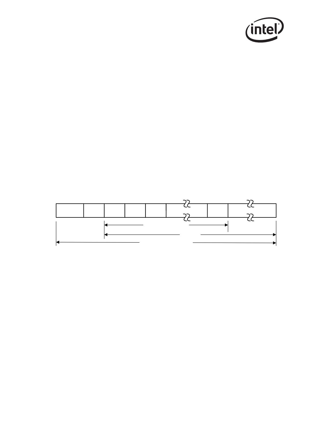
Carrier extension provides a method to increase the duration of the carrier event to a minimum
usable duration in order to meet the collision domain objective. Packets that are signaled from the
CSMA/CD layer that do not meet the minimum slot time of 512 bytes have extension bytes
appended to them in order to meet this minimum slot time requirement. The extension bytes are
defined within the context of the frame encapsulation discussion of the 802.3z standard and are
recognized by 802.3z compliant devices (see Figure 8-1).
Preamble
SFD
DA
SA
T/L
Data/Pad
FCS
Extension
Minimum Frame Size
Slot Time
Duration of Carrier Event
Figure 8-1. Carrier Extended Frame Format
The Ethernet controller supports the reception and transmission of carrier extended packets. Carrier
extension is implemented via specifying the collision distance parameter, COLD, in the Transmit
Control register (TCTL). Note that this field is evaluated whether in full- or half- duplex operation.
8.4.2.2
Packet Bursting
In an attempt to recover some of the lost overhead encountered with short duration packets using
carrier extension, the IEEE 802.3z standard incorporates the implementation of packet bursting.
Packet bursting is a mechanism that allows a transmitting device to “own-the-wire” for a longer
duration and “pack” extra packets in a burst without relinquishing ownership of the medium. A
burst length timer is implemented which allows the Ethernet controller to continue to send packets
until the timer expires (if packets are available for transmission).
In the case where a transmitting station has more than one packet to send, it can transmit the first
packet (extending to 512 bytes if necessary) and then begin the transmission of subsequent packets.
Packet transmission can continue until either there are no more packets ready for transmission, or
the burst timer has expired. The burst timer limit is specified as 8 KB.
160
Ethernet Interface
The normal rules for IPG are followed during packet bursting after the first packet has met the
minimum slot time requirements, with the exception that the Inter Frame Content (IFC) is
extension symbols rather than IDLEs. Under some circumstances, it might be desirable to extend
this IPG time during a burst. This can be done via the AIFS field in the AIT register. See Section
13.4.35.
8.5
Auto-Negotiation and Link Setup1
Configuration of the link can be accomplished by several methods ranging from software forcing
the link settings to Auto-Negotiation by the internal PHY. Section 8.6.1 describes the process of
bringing the link up including configuration of the MAC and PHY, as well as the various methods
of determining duplex and speed configuration.
The PHY performs Auto-Negotiation per 802.3ab clause 40 and extensions to clause 28. Link
resolution is obtained from the PHY after the link has been established via the MDIO interface, by
the controller via specific input signals from the PHY or by the controller’s specific auto detection
functions.
Upon power up, or device reset via the RST# input, the controller initiates Auto-Negotiation based
on the default settings in the Device Control and Transmit Configuration Word registers, as well as
settings read from the EEPROM. If enabled in the EEPROM, the Ethernet controller will immedi-
ately perform Auto-Negotiation.
8.6
Auto-Negotiation and Link Setup2
Configuration of the link can be accomplished by several methods ranging from software forcing
the link settings to Auto-Negotiation by either the MAC (Internal Serdes mode) or the internal
PHY (GMII/MII mode). The following sections describe the process of bringing the link up
including configuration of the MAC and PHY, as well as the various methods of determining
duplex and speed configuration.
The process of determining link configuration differs slightly depending on the Ethernet controller
type and version. In Internal Serdes mode, the MAC performs Auto-Negotiation per clause 37 of
the 802.3z standard. The transceiver used in this mode (the SerDes) does not participate in the
Auto-Negotiation process as all aspects of Auto-Negotiation are controlled by the MAC.
For internal PHY mode, the PHY performs Auto-Negotiation per 802.3ab clause 40 and extensions
to clause 28. Link resolution is obtained from the PHY after the link has been established via the
MDI/O interface, by the Ethernet controller via specific input signals from the PHY, or by the
Ethernet controller’s specific auto detection functions.
The method for configuring the link between two link partners is highly dependent on the mode of
operation as well as the functionality provided by the specific physical layer device (PHY or
SerDes). For Internal Serdes mode, the Ethernet controller provides the complete 802.3z PCS
function on-chip. For GMII/MII mode, the PCS and Auto-Negotiation functions are maintained
within the PHY.
1.
82541xx, 82547GI/EI, and 82540EP/EM only.
2.
Applicable to the 82546GB/EB, 82545GM/EM, and 82544GC/EI only.
161
Ethernet Interface
The following section describes the link configuration process in the Internal Serdes for the
82546GB/EB and 82545GM/EM (TBI mode for the 82544GC/EI) and internal PHY modes.
8.6.1
Link Configuration in Internal Serdes/TBI Mode1
Internal Serdes for the 82546GB/EB and 82545GM/EM (TBI for the 82544GC/EI) Mode link
configuration can be performed via the on-chip PCS function in the Ethernet controller. The
hardware supports both hardware and software Auto-Negotiation methods for determining the link
configuration, as well as allowing for manual configuration to force the link.
Hardware Auto-Negotiation is the preferred method.
8.6.1.1
Link Speed
Internal Serdes for the 82546GB/EB and 82545GM/EM (TBI for the 82544GC/EI) Mode is only
defined for 1000 Mb/s operation. Other link speeds are not supported.
When the 82546GB/EB and 82545GM/EM is in internal Serdes mode, the speed determination
function is disabled and the Device Status register bits (STATUS.SPEED) bits indicate a value of
10b for 1000 Mb/s.
For the 82544GC/EI, when the TBI_MODE input is asserted for TBI mode, the speed
determination function is disabled and the Device Status register bits (STATUS.SPEED) bits
indicate a value of 10b for 1000 Mb/s.
8.6.1.2
Auto-Negotiation
At power up, or Ethernet controller reset via the RST# input, it initiates Auto-Negotiation based on
the default settings in the Device Control and Transmit Configuration Word registers, as well as
settings read from the EEPROM. If enabled in the EEPROM, the Ethernet controller immediately
performs Auto-Negotiation.
TBI Mode Auto-Negotiation, as defined in clause 37 of the IEEE 802.3z standard, provides a
protocol for two Ethernet controllers to advertise and negotiate a common operational mode across
a Gigabit Ethernet link. The Ethernet controller fully supports the IEEE 802.3z Auto-Negotiation
function when using the internal Serdes mode for the 82546GB/EB and 82545GM/EM or when
using the TBI and on-chip PCS for the 82544GC/EI.
TBI Mode Auto-Negotiation is used to determine the following information:
• Duplex resolution
• Flow control configuration
Speed for Internal Serdes mode (TBI mode for the 82544GC/EI) is fixed at 1000 Mb/s, so speed
settings in the Device Control register are unaffected by the Auto-Negotiation process.
There are two implementations accessible in the design:
1. A full hardware Auto-Negotiation implementation that does not require software intervention
in order to successfully reach a negotiated link configuration.
2. Software driven negotiation.
1.
TBI mode for the 82544GC/EI.
162

Ethernet Interface
A set of registers is provided to facilitate either hardware or software Auto-Negotiation.
The hardware supports both hardware and software Auto-Negotiation methods for determining
link configuration as well as allowing for manual configuration to force the link. The IEEE 802.3z
specification defines a set of resources that software can use to control a hardware implementation
of Auto-Negotiation, but this definition is sub-optimal for Internal Serdes mode (TBI mode for the
82544GC/EI) and hardware Auto-Negotiation is the preferred method.
In addition, it specifies optional resources that exist only to support the exchange of “Next Pages”,
something that is not required for the Ethernet controller. The hardware defined in this
specification accepts and exchanges next pages in Internal Serdes mode (TBI mode for the
82544GC/EI), but does so by dropping all incoming next pages and sending only null next pages.
The Ethernet controller can only send null next pages when in hardware Auto-Negotiation. A full
next page exchange can take place if software performs Auto-Negotiation.
The Ethernet controller fully complies with IEEE 802.3z with respect to next page exchange in that
both link partners must request next page exchange in order to do so.
8.6.1.3
Hardware Auto-Negotiation
Hardware supports negotiation of the link configuration per clause 37 of the 802.3z standard. This
is accomplished by the exchange of /C/ ordered sets that contain the txConfigWord register values
from TXCW in the third and fourth symbols of the ordered sets.
Bits FD and LU of the Device Status register (STATUS), and ANC of the RXCW register provide
status information regarding the negotiated link.
Auto-Negotiation can be initiated by the following:
• LRST transition from 1b to 0b in CTRL register
• ANE transition from 0b to 1b in TXCW register
• Receipt of /C/ ordered set during normal operation
• Receipt of different value of the /C/ ordered set during the negotiation process
• Transition from loss of synchronization to synchronized state (if ANE is enabled)
Resolution of the negotiated link determines device operation with respect to flow control
capability and duplex settings. These negotiated capabilities override advertised and S/W
controlled device configuration.
Software must configure the TXCW.txConfigWord field to the desired advertised base page. The
bits in the Device Control register are not mapped to the txConfigWord field in hardware until after
Auto-Negotiation completes. The Figure 8-2 and Figure 8-3 show txConfigWord and the mapping
to the Config_reg Base Page encoding per clause 37 of the standard. Table 8-2 lists the bit contents.
15
14
13
12
11
10
9
8
7
6
5
4
3
2
1
0
RS
RS
RS
RS
RS
RS
RS
RS
RS
RS
RS
Np
AS
PS
Hd
Fd
V
V
V
V
V
V
V
V
V
V
V
Figure 8-2. TXCW.txConfigWord
15
14
13
12
11
10
9
8
7
6
5
4
3
2
1
0
RS
RS
RS
RS
RS
RS
RS
RS
Np
Ack
Rf2
Rf1
Ps2
Ps1
Hd
Fd
V
V
V
V
V
V
V
V
163

Ethernet Interface
Figure 8-3. 802.3z Advertised Base Page Mapping
Table 8-2. Bits Content in TXCW.txConfigWord
Bit
Description
Next Page Indication
Np
When set indicates a request for next page exchange
Asymmetric Pause Connection is Desired
When set, results in independent enabling/disabling of the flow control
AS
receive and transmit. When cleared, results in symmetric enabling/disabling
of the flow control receive and transmit
Pause Function
When set, indicates that the Ethernet controller is capable and intends to
PS
stop upon reception of 802.3x flow control Pause packets.
When cleared, indicates that the Ethernet controller is not capable, or does
not intend to stop upon reception of flow control Pause packets.
Half-Duplex Ability
HD
When set, indicates that the Ethernet controller is capable of working in
half-duplex mode of operation
Full Duplex Ability
FD
When set, indicates that the Ethernet controller is capable of working in full-
duplex mode of operation
Reserved
RSV
Should be written as 0b
The reserved bits should be written as zero. The remote fault bits [13:12] can be set by software to
indicate remote fault type to the link partner if desired. The AS and PS bits are used for
advertisement of PAUSE frame operation. Refer to clause 37 of the 802.3z specification for details.
8.6.1.4
Software Auto-Negotiation
Auto-Negotiation can also be performed by software with TXCW.ANE set to 0b. Data stored in the
txConfigWord field is transmitted during the configuration process. Software should not (in
general) read back the contents of this register.
If hardware loses receive synchronization, the contents of the TXCW register changes and during
the time of the change, the value read back can be inconsistent. In the absence of loss of
synchronization, the value read back is stable and equal to the last written value.
Software controls the negotiation process by writing the appropriate values to the txConfigWord
and transmitting /C/ ordered sets by setting txConfig (in TXCW) to 1b. Software must monitor the
RXCW register for status of the negotiation process and respond via writes to the TXCW register
appropriately.
The software algorithm must follow the state machine implementation of sub-clause 37.3.1.5 of
IEEE 802.3z, Figure 37-6. The link timer specification is 10 ms (+10 ms/-0 ms). In some systems,
response time for the S/W implementation can make it difficult to meet this requirement if system
utilization is high due to latencies on the PCI bus.
For more information, refer to the register definitions for TXCW and RXCW in Sections 13.4.13
and 13.4.14, respectively.
164
Ethernet Interface
8.6.1.5
Forcing Link
In cases where the Ethernet controller is connected to a non-Auto-Negotiating link partner, the
hardware allows for manual configuration of the link via the Device Control register (CTRL).
Forcing link can be accomplished by software writing a 1b to CTRL.SLU which forces the TBI
PCS logic into a link up state if the LOS input is not asserted. Setting the SLU bit enables the MAC
to communicate with the internal SerDes and allows recognition of the LOS signal. If auto-
negotiation is enabled (TXCW.ANE = 1b) Set Link Up is ignored. The LINK UP# output, as well
as internal status logic, indicates link status.
The TXCW.ANE bit must be set to logic 0b to allow for forcing link. When link is forced via the
CTRL.SLU bit, the link cannot come up unless the LOS input is deasserted, implying there is a
valid signal being received by the optics or the SerDes.
An interrupt bit, RXCFG, flags software that the hardware is receiving configuration symbols (/C/
codes). Software should mask (enable) this interrupt when forcing link. When the link is forced, the
link partner can begin to Auto-Negotiate based due to a reset or enabling of Auto-Negotiation. The
reception of /C/ codes causes an interrupt to software and the proper hardware configuration can be
set.
8.6.2
Internal GMII/MII Mode
Link configuration in GMII/MII mode is generally determined by the PHY via Auto-Negotiation.
The software driver must intervene in cases where a successful link is not negotiated or a
programmer desires to manually configure the link. The following sections discuss the methods of
link configuration for internal PHY mode.
8.6.2.1
Auto-Negotiation
In GMII/MII mode, the PHY performs the Auto-Negotiation function. The operational details of
this function are described in the IEEE P802.3ab draft standard.
Auto-Negotiation provides a method for two link partners to exchange information in a systematic
manner in order to establish a link configuration providing the highest common level of
functionality supported by both partners. Once configured, the link partners exchange
configuration information to resolve link settings such as:
• Speed: 10/100/1000 Mb/s
• Duplex: Full- or Half-
• Flow Control Operation
PHY specific information required for establishing the link is also exchanged, but is not relevant to
the operation of the Ethernet controller.
If flow control is enabled in the MAC, the settings for the desired flow control behavior must also
be made by software in the PHY and Auto-Negotiation must be restarted. After Auto-Negotiation
completes, the software driver must read the MII registers in the PHY to determine the resolved
flow control behavior of the link and reflect these parameters in the Ethernet controller register
(CTRL.TFCE and CTRL.RFCE).
165
Ethernet Interface
Once PHY Auto-Negotiation is complete, the PHY asserts the link indication signal. Software
MUST set the “set link up” bit in the Device Control Register (CTRL.SLU) before the Ethernet
controller recognizes the link. Setting the SLU bit permits the MAC to recognize the LINK signal
from the PHY, which indicates the PHY has gotten the link up, and to receive and transmit data.
8.6.2.2
Link Speed
The speed of the link in GMII/MII mode can be determined by several methods with the Ethernet
controller. These include:
• Software forced configuration of link speed
• Automatically detecting the Auto-Negotiated speed from the PHY
• Direct indication of speed configuration from the PHY
These methods are discussed in the following sections.
8.6.2.2.1
Forcing Speed
There can be circumstances when the software driver must force the link speed of the Ethernet
controller. This can occur when the link is manually configured.
The software driver can force speed in the MAC by setting the CTRL.FRCSPD (force-speed) bit to
1b, and then setting the speed bits in the Device Control register (CTRL.SPEED) to the desired
speed setting. See Section 13.4.1 for details.
When forcing the Ethernet controller to a specific speed configuration, the driver must also ensure
the PHY is configured to a speed setting consistent with the MAC. This statement implies that
software accesses to the PHY either force the speed, or read the MII management status register
bits that indicate link speed within the PHY itself.
Forcing the speed setting with CTRL.SPEED also can be accomplished by setting the
CTRL_EXT.SPD_BYPS bit. This bit bypasses the internal clock switching logic, and gives
complete control to the driver when the speed setting takes place. The CTRL.FRCSPD bit uses the
internal clock switching logic, which delays the effect of the speed change.
8.6.2.2.2
Using Auto-Speed Detection (ASD)
The Ethernet controller provides a method in hardware for automatically sensing the speed of the
link by observing the receive clock signal generated by the PHY once the link is established. The
Auto-Speed Detection (ASD) function is enabled via the ASDE bit in the Device Control register
(CTRL.ASDE). ASD provides a method of determining the link speed without the need for
software accesses to the MII management registers. ASD is not supported in Internal Serdes mode
for the 82546GB/EB and 82545GM/EM or TBI mode for the 82544GC/EI.
In internal PHY mode, the internal receive clock input operates at the byte rate of the link interface.
By sensing this clock, the Ethernet controller makes a determination of the link speed and sets the
proper configuration in the control registers without software intervention.
The ASD function is initiated upon the assertion of a valid link by the PHY via an internal signal
input. After the speed is detected, the Device Control and Device Status register bits are set and
reflect the speed of the link. As described earlier, software must set the CTRL.SLU bit to allow the
speed selection to take effect.
166
Ethernet Interface
STATUS.ASDV [9:8], provides the results of speed status indication for diagnostics purposes
regardless of whether the Auto-Speed Detection feature is enabled. This function is initiated with a
write to the CTRL_EXT.ASDCHK bit. See Section 13.4.6 for details.
8.6.2.2.3
Automatic Detection of Link Speed using SPD-IND
With the CTRL register configure as CTRL.FRCSPD = 0, the speed is reconfigured automatically
each time a new linkup event is detected. This configuration is recommended why the PHY is
configured for Auto-Negotiation.
8.6.2.3
Duplex
The duplex configuration of the link is also resolved during the Auto-Negotiation process. As
previously mentioned, the Ethernet controller supports both full- and half-duplex operation in
internal PHY mode. When the PHY asserts its link signal to the MAC, it also communicates the
duplex setting.
Software can override the duplex setting via the CTRL.FD bit when the CTRL.FRCDPLX (force
duplex) bit is set. If CTRL.FRCDPLX is 0b, the CTRL.FD bit is ignored.
8.6.2.4
MII Management Registers
The software driver is required under some circumstances to read from, or write to, the MII
management registers in the PHY. These accesses are performed via the MDIC registers. The MII
registers allow the software driver to have direct control over the PHY’s operation, which includes:
• Resetting the PHY
• Setting preferred link configuration for advertisement during the Auto-Negotiation process
• Restarting the Auto-Negotiation process
• Reading Auto-Negotiation status from the PHY
• Forcing the PHY to a specific link configuration
• Extended capabilities
The standard set of PHY management registers can be found in the IEEE P802.3ab standard.
8.6.2.5
Comments Regarding Forcing Link
Forcing link in GMII/MII mode requires the software driver to configure both the MAC and the
PHY in a consistent manner with respect to each other as well as the link partner. After
initialization, the software driver configures the desired modes in the MAC, then accesses the PHY
MII registers to set the PHY to the same configuration.
In internal PHY mode, setting the CTRL.SLU bit forces a link up condition in the MAC. The
duplex setting at this point should be forced by software on the CTRL.FD bit.
167

Ethernet Interface
8.6.3
Internal SerDes Mode1 Control Bit Resolution
Tables 8-3, 8-4, and 8-52 list how on-chip Auto-Negotiation affects control bits in the Ethernet
controller. Table 8-5 lists the case where software Auto-Negotiation is not performed and link is
forced.
Table 8-3. Internal Serdes Mode1 - Hardware Enabled
TXCW.ANE = 1b
Control Bit
Effect on Control Bits
CTRL.FD
Ignored; duplex is set by priority resolution of TXCW and RXCW
CTRL.SLU
Ignored; it is not possible to force link configuration (ANE takes precedence)
CTRL.RFCE
Set by priority resolution (read only)
CTRL.TFCE
Set by priority resolution (read only)
CTRL.SPEED
No impact; speed always 1000 Mb/s in Internal Serdesa mode
STATUS.FD
Set by priority resolution
STATUS.LU
Duplicate of RXCW.ANC (Auto-Negotiation complete)
STATUS.SPEED
Internal SerDesa Mode is always 1000 Mb/s; fixed at 10b
a.
TBI for the 82544GC/EI.
Table 8-4. Internal Serdes1 Mode - Software Enabled
TXCW.ANE = 0b
Control Bit
Effect on Control Bits
CTRL.FD
Duplex is set by software priority resolution
CTRL.SLU
Set by software when Auto-Negotiation is complete.
CTRL.RFCE
Set by software as a result of software priority resolution
CTRL.TFCE
Set by software as a result of software priority resolution
CTRL.SPEED
No impact; speed always 1000 Mb/s in Internal SerDesa mode
STATUS.FD
Reflects the value of CTRL.FD
STATUS.LU
Reflects CTRL.SLU and internal link indication
STATUS.SPEED
Internal Serdesa Mode is always 1000 Mb/s; fixed at 10b
a.
TBI for the 82544GC/EI.
1.
TBI Mode for the 82544GC/EI.
2.
Not applicable to the 82541xx, 82547GI/EI, or 82540EP/EM.
168

Ethernet Interface
Table 8-5. Internal Serdes Mode1 - Auto-Negotiation Skipped
TXCW.ANE = 0b
Control Bit
Effect on Control Bits
CTRL.FD
Duplex is set by software for the desired mode of operation
CTRL.SLU
Set by software
CTRL.RFCE
Set by software for the desired mode of operation
CTRL.TFCE
Set by software for the desired mode of operation
CTRL.SPEED
No impact; speed always 1000 Mb/s in Internal SerDesa mode
STATUS.FD
Reflects the value of CTRL.FD
STATUS.LU
Reflects CTRL.SLU and internal link indication
STATUS.SPEED
Internal SerDesa Mode is always 1000 Mb/s; fixed at 10b
a.
TBI for the 82544GC/EI.
8.6.4
Internal PHY Mode Control Bit Resolution
Tables 8-6, 8-7, 8-8, and 8-9 list how Auto-Negotiation affects control bits in the Ethernet
Controller.
Refer to IEEE 802.3z, clause 37 for information related duplex and flow control link resolution per
the 802.3z Auto-Negotiation method. The Ethernet controller fully complies to the specified
resolution functions.
Table 8-6. GMII/MII Mode - PHY Speed Indication
CTRL.FRCSPD = CTRL.ASDE = CTRL.FRCDPLX = 0b
Control Bit
Effect on Control Bits
CTRL.FD
Duplex is set per internal signal after link up assertion by PHY.
CTRL.SLU
Software should set to allow PHY to control.
Must be set by software after reading flow control resolution from MII
CTRL.RFCE
registers.
Must be set by software after reading flow control resolution from MII
CTRL.TFCE
registers.
CTRL.SPEED
Ignored; no impact on speed.
STATUS.FD
Reflects the value of CTRL.FD as above.
STATUS.LU
Reflects link status and SLU set.
Speed status bits reflect speed resolved from speed indication inputs from
STATUS.SPEED
PHY.
1.
TBI for the 82544GC/EI.
169

Ethernet Interface
Table 8-7. GMII/MII Mode - Auto-Speed Detection
CTRL.FRCSPD = CTRL.FRCDPLX = 0b; CTRL.ASDE = 1b
Control Bit
Effect on Control Bits
CTRL.FD
Duplex is set per internal duplex indication after link up assertion by PHY.
CTRL.SLU
Software should set to allow PHY to control.
Must be set by software after reading flow control resolution from MII
CTRL.RFCE
registers.
Must be set by software after reading flow control resolution from MII
CTRL.TFCE
registers.
CTRL.SPEED
Ignored; no impact on speed.
STATUS.FD
Reflects the value of CTRL.FD as above.
STATUS.LU
Reflects internal link status
STATUS.SPEED
Speed status bits reflect speed resolved from ASD function.
Table 8-8. GMII/MII Mode - Force Speed
CTRL.FRCSPD = 1b; CTRL.FRCDPLX = 0b; CTRL.ASDE = X
Control Bit
Effect on Control Bits
CTRL.FD
Duplex is set per internal duplex indicates input after link up assertion by PHY.
CTRL.SLU
Software should set to allow PHY to control.
Must be set by software after reading flow control resolution from MII
CTRL.RFCE
registers.
Must be set by software after reading flow control resolution from MII
CTRL.TFCE
registers.
CTRL.SPEED
Set by software to set speed of the MAC; must match PHY speed settings.
STATUS.FD
Reflects the value of CTRL.FD.
STATUS.LU
Reflects internal link status.
STATUS.SPEED
Speed status bits reflect speed forced by CTRL.SPEED.
170

Ethernet Interface
Table 8-9. GMII/MII Mode - Force Link
CTRL.FRCSPD = CTRL.FRCDPLX = CTRL.SLU = 1b
Control Bit
Effect on Control Bits
CTRL.FD
Set by software.
CTRL.SLU
Set by software, and assumed PHY is also forced to assert link.
CTRL.RFCE
Set by software for the desired mode of operation.
CTRL.TFCE
Set by software for the desired mode of operation.
CTRL.SPEED
Set by software.
STATUS.FD
Reflects the value of CTRL.FD.
STATUS.LU
Reflects CTRL.SLU set and internal link status.
STATUS.SPEED
Reflects CTRL.SPEED.
8.6.5
Loss of Signal/Link Status Indication
For the 82546GB/EB and 82545GM/EM, the internal LOS signal allows for indication of physical
link status to the Ethernet controller’s MAC.
For the 82544GC/EI, the LOS input is provided to allow for indication of physical link status to
the Ethernet controller. When the 82544GC/EI is configured in TBI mode, the input is typically
connected to the loss-of-signal connection from the optics while in internal PHY mode.
If the LSC (Link Status Change) interrupt is enabled, the hardware posts an interrupt to be serviced
by the software driver when the link goes up or down. See Section 3.4.3 for more details.
8.6.5.1
Internal Serdes Mode 1
When asserted, LOS indicates there is no activity on the fiber due to either an unplugged cable or a
defective optical device. An assertion on LOS implies the link is not available and the hardware is
disabled. This is true whether the link is forced by the Set Link Up bit (CTRL.SLU) or if the
Ethernet controller is configured to perform Auto-Negotiation. When Auto-Negotiation is enabled,
the Ethernet controller is forced to restart Auto-Negotiation but does not complete the negotiation
process until the LOS is deasserted.
8.6.5.2
Internal PHY Mode
While in internal PHY mode, an internal signal provides status of the physical link as indicated by
the PHY. Indication that the link is not up disables MAC operation. Upon determination of a valid
link, the assertion of the internal link signal asserts the LSC interrupt (if enabled) to indicate to the
software driver to check the link status.
1.
TBI mode for the 82544GC/EI.
171
Ethernet Interface
8.7
10/100 Mb/s Specific Performance Enhancements
8.7.1
Adaptive IFS1
The Ethernet controller supports back-to-back transmit Inter-Frame-Spacing (IFS) of 960 ns in 100
Mb/s operation and 9.6 s in 10 Mb/s operation. Although back-to-back transmission is normally
desirable, sometimes it can actually hurt performance in half-duplex environments due to excessive
collisions. Excessive collisions are likely to occur in environments where one station is attempting
to send large frames back-to-back, while another station is attempting to send acknowledge (ACK)
packets.
The Ethernet controller contains an Adaptive IFS Throttle - AIT register (see Section 13.4.35) that
enables the implementation of a driver-based adaptive IFS algorithm for collision reduction.
Adaptive IFS throttles back-to-back transmissions in the transmit MAC and delays their transfer to
the CSMA/CD transmit function. Normally, this register should be set to zero. However, if
additional delay is desired between back-to-back transmits, then this register can be set with a
value greater than zero. By setting this register with a higher value, collisions can be reduced in
certain half-duplex environments, because the adapter is less aggressive in acquiring the wire, and
therefore less likely to collide with another adapter that attempts to transmit after minimum IFS.
Note: IFS and IPG (inter-packet gap) are equivalent terms and may be used interchangeably in this
manual.
The AIFS field provides a similar function to the IGPT field in the TIPG register (see Section
13.4.34). However this Adaptive IFS throttle register counts in units of transmit clocks (which are
8 ns, 80 ns, 800 ns for 10, 100, 1000 Mb/s mode respectively), and is 16 bits wide, thus providing a
greater maximum delay value.
Using values lower than a certain minimum (determined by the ratio of transmit clock to link
speed), has no effect on back-to-back transmission. This is because the Ethernet controller does not
start transmission until the minimum IEEE IFS (9.6 us at 10 Mb, 960 ns at 100 Mb, and 96 ns at 1
Gb) has been met regardless of the value of Adaptive IFS. For example, if the Ethernet controller is
configured for 100 Mb/s operation, the minimum IEEE IFS at 100 Mb/s is 960 ns. Setting AIFS to
a value of 10 (decimal) would not affect back-to-back transmission time on the wire, because the
800 ns delay introduced (10 * 80n s = 800 ns) is less than the minimum IEEE IFS delay of 960 ns.
However, setting this register with a value of 20 (decimal), which corresponds to 1600 ns for the
above example, would delay back-to-back transmits because the ensuing 1600 ns delay is greater
than the minimum IFS time of 960 ns.
It is important to note that this register has no effect on transmissions that occur immediately after
receives or on transmissions that are not back-to-back (unlike the IPGR1 and IPGR2 values in the
TIPG register described in Section 13.4.34). In addition, Adaptive IFS also has no effect on re-
transmission timing (re-transmissions occur after collisions). Therefore, AIFS is only enabled in
back-to-back transmission. The AIFS value is NOT additive to the TIPG.IPGT value; instead, the
actual IPG equals the larger of AIFS and TIPG.IPGT.
1.
Not applicable to the 82541xx or 82547GI/EI.
172

Ethernet Interface
8.7.2
Flow Control
Flow control as defined in IEEE specification 802.3x, as well as the specific operation of
asymmetrical flow control defined by 802.3z, are supported. The following registers are defined
for the implementation of flow control:
Table 8-10. Flow Control Registers
Register Name
Description
Flow Control Address Low, High (FCAL/H)
6-byte flow control multicast address
13-bit high water mark indicating receive
Flow Control Receive Thresh Hi (FCRTH)
buffer fullness
16 bit timer value to include in transmitted
Flow Control Transmit Timer Value (FCTTV)
PAUSE frame
Flow Control Type (FCT)
16-bit field to indicate flow control type
13-bit low water mark indicating receive
Flow Control Receive Thresh Lo (FCRTL)
buffer emptiness
Flow control is implemented as a means of reducing the possibility of receive buffer overflows
which result in the dropping of received packets, and allows for local control of network
congestion levels. This can be accomplished by sending an indication to a transmitting station of a
nearly-full receive buffer condition at a receiving station.
The implementation of asymmetric flow control allows for one link partner to send flow control
packets while being allowed to ignore their reception. For example, not required to respond to
PAUSE frames.
For the 82541xx and 82547GI/EI, there are two forms of flow control that can be established via
auto-negotiation: symmetric and asymmetric. Symmetric flow control is for point-to-point links;
asymmetric for hub-to-end-node connections. Symmetric flow control allows either node to flow-
control the other. Asymmetric flow control allows a repeater or switch to flow-control a DTE, but
not vice versa
8.7.3
MAC Control Frames & Reception of Flow Control Packets
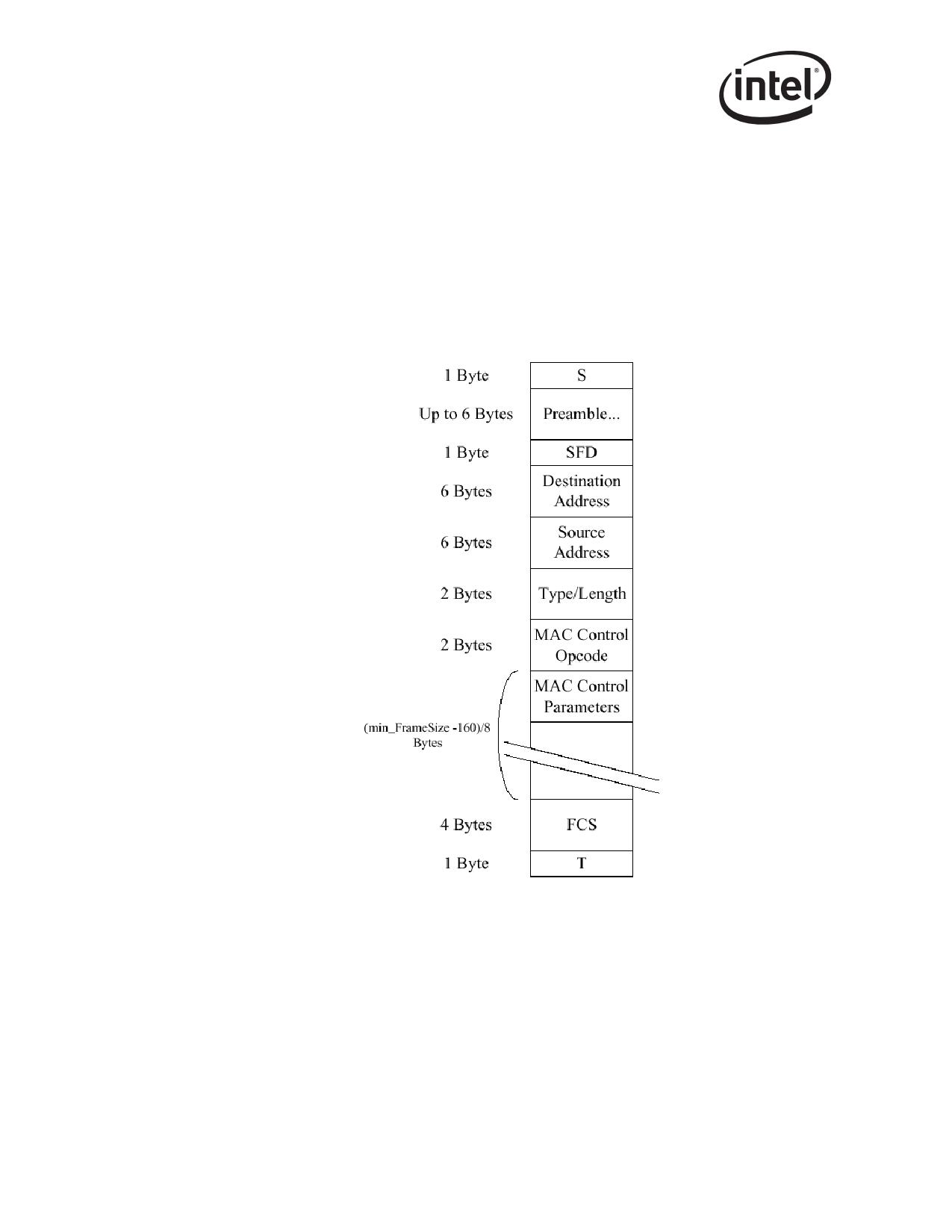
Three comparisons are used to determine the validity of a flow control frame:
1. A match on the 6-byte multicast address for MAC Control Frames or to the station address of
the device (Receive Address Register 0).
2. A match on the type field.
3. A comparison of the MAC Control Opcode field.
Standard 802.3x defines the MAC Control Frame multicast address as 01_80_C2_00_00_01h. This
address must be loaded into the Flow Control Address Low/High registers (FCAL/H).
The Flow Control Type register (FCT) contains a 16-bit field that is compared against the flow
control packet’s type field to determine if it is a valid flow control packet: XON or XOFF. 802.3x
reserves this value as 8808h. This number must be loaded into the Flow Control Type (FCT)
register.
173
Ethernet Interface
The final check for a valid PAUSE frame is the MAC Control Opcode. At this time only the
PAUSE control frame opcode is defined. It has a value of 0001h.
Frame based flow control differentiates XOFF from XON based on the value of the PAUSE timer
field. Non-zero values constitute XOFF frames while a value of zero constitutes an XON frame.
Values in the timer field are in units of slot time. A “slot time” is hard wired to 64 byte times, or
512 ns.
Note:
“S” is the Start-of-Packet delimiter and “T” is the first part of the End-of-
Packet delimiters for 802.3z encapsulation.
Figure 8-4. 802.3x MAC Control Frame Format
The receiver is enabled to receive flow control frames if flow control is enabled through the RFCE
bit in the Device Control register (CTRL). Software sets this bit consistently with the advertised
capability in the Transmit Configuration Word Register (TXCW).
174
Ethernet Interface
Flow control capability must be negotiated between link partners via the Auto-Negotiation process.
The Auto-Negotiation process can modify the value of these bits based on the resolved capability
between the local device and the link partner.
Once the receiver has validated the reception of an XOFF, or PAUSE frame, the Ethernet controller
performs the following:
• Increment the appropriate statistics register(s)
• Set the TXOFF bit in the Device Status Register (STATUS)
• Initialize the pause timer based on the packet’s PAUSE timer field
• Disable packet transmission or schedule the disabling of transmission after the current packet
completes.
Resumption of transmission can occur under the following conditions:
• Expiration of the PAUSE timer
• Reception of on XON frame (a frame with its PAUSE timer set to 0b)
Either condition clears the STATUS.TXOFF bit and transmission can resume. Hardware records
the number of received XON frames in the XONRXC counter.
8.7.4
Discard PAUSE Frames and Pass MAC Control Frames
Note: When receive flow control is enabled (CTRL.RFCE) is 1b, the following special filtering is
performed on PAUSE and MAC Control frames. When receive flow control is disabled, these
frames are filtered like any other frames and the rest of this section can be ignored.
Two bits in the Receive Control register (RCTL) are implemented specifically for control over
receipt of PAUSE and MAC control frames. These bits are Discard PAUSE Frames (DPF) and Pass
MAC Control Frames (PMCF). See Section 13.4.22 for DPF and PMCF bit definitions.
The DPF bit forces the discarding of any valid PAUSE frame addressed to the Ethernet controller’s
station address. If the packet is a valid PAUSE frame and is addressed to the station address
(receive address [0]), the Ethernet controller does not pass the packet to host memory if the DPF bit
is set to logic high. The DPF bit does not affect pause frames that are addressed to the MAC control
frame multicast address (01-80-C2-00-00-01). These frames are DMA’ed if they pass standard
address filtering, including receive address 1 to 15, multicast hash filtering, or the Multicast
Promiscuous bit is enabled. TheDPF has no affect on PAUSE operation, only the DMA function.
The PMCF bit allows for the passing of any valid MAC control frames to the system which do not
have a valid PAUSE opcode. In other words, the frame can have the correct MAC control frame
multicast address (or the MAC station address) as well as the correct type field match with the FCT
register, but does not have the defined PAUSE opcode of 0001h. Frames of this type are transferred
to host memory when PMCF is logic high. The results of this filter are logically ORed into the
standard filters, so even if PMCF is 0b, any MAC control frame that isn't a PAUSE frame that
passes standard address filtering is DMA’ed
175
Ethernet Interface
8.7.5
Transmission of PAUSE Frames
Transmitting PAUSE frames is enabled by software writing a 1b to the CTRL.TFCE bit. This bit is
mapped to bit 8 of the TXCW txConfigWord field. (ASM_DIR bit).
Similar to the reception flow control packets described earlier, XOFF packets can be transmitted
only if this configuration has been negotiated between the link partners via the Auto-Negotiation
process. In other words, the setting of this bit indicates the desired configuration. The resolution of
the Auto Negotiation process is discussed in Sections 8.6.3 and 8.6.4.
The contents of the Flow Control Receive Threshold High register (FCRTH) determine at what
point hardware transmits a PAUSE frame. Hardware monitors the fullness of the receive FIFO and
compares it with the contents of FCRTH. When the threshold is reached, hardware sends a PAUSE
frame with its pause time field equal to FCTTV. Once the receive buffer fullness reaches the low
water mark, hardware sends an XON message (a PAUSE frame with a timer value of 0b). Software
enables this capability with the XONE field of the FCRTL.
Hardware sends one more PAUSE frames if it has previously sent one and the FIFO overflows (so
the threshold must not be set greater than the FIFO size). This function is intended to minimize the
number of packets dropped if the first PAUSE frame does not reach its target.
Transmitting Flow Control frames should only be enabled in full duplex mode per the IEEE 802.3
standard. Software should ensure that the transmission of flow control packets is disabled when the
Ethernet controller is operating in half-duplex mode.
8.7.6
Software Initiated PAUSE Frame Transmission
The Ethernet controller has the added capability to transmit an XOFF frame through software. This
function is accomplished by software writing a 1b to the SWXOFF bit of the Transmit Control
register (TCTL). Once this bit is set, hardware initiates the transmission of a PAUSE frame in a
manner similar to that automatically generated by hardware.
The SWXOFF bit is self clearing after the PAUSE frame has been transmitted.
The state of the CTRL.TFCE bit or the negotiated flow control configuration does not affect
software generated PAUSE frame transmission.
Software sends an XON frame by programming a zero in the PAUSE timer field of the FCTTV
register.
Caution: Use of SWXOFF is not recommended due to security concerns.
8.7.7
External Control of Flow Control Operation1
Transmitting XOFF and XON frames can be triggered by external pins. When enabled through
FCRTH.XFCE, the XOFF and XON inputs can be used to provide external effective threshold
information that initiate XOFF and XON transmission, respectively.
1.
82544GC/EI only.
176
Ethernet Interface
When the XOFF signal is asserted high, the device transmits a single XOFF frame. The assertion of
I_XON (after deassertion of XOFF) initiates an XON frame transmission if enabled by
FCRTL.XONE. The assertion/deassertion of XON is required between assertions of XOFF in order
to send another XOFF frame, providing a built-in hysteresis mechanism.
Output signals are also provided from the 82544GC/EI to indicate the device is either above the
programmed flow control high threshold or below the flow control low threshold (ABV_HI and
BLW_LOW respectively).
Flow control transmission must also be enabled through CTRL.TFCE.
177
Ethernet Interface
Note: This page intentionally left blank.
178

802.1q VLAN Support
9
The PCI/PCI-X Family of Gigabit Ethernet Controllers provide several specific mechanisms to
support 802.1q VLANs:
• Optional adding (for transmits) and stripping (for receives) of IEEE 802.1q VLAN tags
• Optional ability to filter packets belonging to certain 802.1q VLANs
Note: The 82541ER Ethernet controller does not support VLAN tags.
9.1
802.1q VLAN Packet Format
Table 9-1 compares the format of an untagged 802.3 Ethernet packet with an 802.1q VLAN tagged
packet. The CRC for the 802.1q tagged frame is re-computed, so that it covers the entire tagged
frame including the 802.1q tag header.
Table 9-1. VLAN Packet Format Comparison
802.1q VLAN
802.3 Packet
#Octets
#Octets
Packet
DA
6
DA
6
SA
6
SA
6
Type/Length
2
8021.q Tag
4
Data
46-1500
Type/Length
2
CRC
4
Data
46-1500
CRC*
4
Maximum frame size for a standard 803.3ac (802.1q VLAN and/or 802.1p priority) packet is 1522
octets as opposed to 1518 octets for a normal 802.3 Ethernet packet. If jumbo frames are used,
enabling 802.3ac adds 4 bytes to the packet to accommodate the q-tag. If multiple descriptors are
required for a transmit, the q-tag information for the packet is extracted from only the last
descriptor of the packet. VLAN tagging is supported independently of packet size.
9.1.1
802.1q Tagged Frames
For 802.1q, the Tag Header field consists of four octets containing the Tag Protocol Identifier
(TPID) and Tag Control Information (TCI), each utilizing 2 octets. The first 16 bits of the tag
header make up the TPID. It contains the “protocol type” which identifies the packet as a valid
802.1q tagged packet.
The two octets making up the TCI contain three fields (see Table 9-2 for details):
• User Priority (UP)
• Canonical Form Indicator (CFI). The CFI should be 0b for transmits. For receives, the
Ethernet controller has the capability to filter out packets that have this bit set. See the CFIEN
and CFI bits in the RCTL as described in Section 13.4.22.
• VLAN Identifier (VID)
179
802.1q VLAN Support
Table 9-2. 802.1q Tagged Frames
Octet 1
Octet 2
UP
CFI
VID
9.2
Transmitting and Receiving 802.1q Packets
Since the 802.1q tag is only four bytes, adding and stripping of tags can done completely in
software. (For transmits, software inserts the tag into packet data before it builds the transmit
descriptor list, and for receives, software strips the four byte tag from the packet data before
delivering the packet to upper layer software.)
However, because adding and stripping of tags in software results in more overhead for the host,
the Ethernet controller has additional capabilities to add and strip tags in hardware, as discussed in
the following two sections.
9.2.1
Adding 802.1q Tags on Transmits
Software can command the Ethernet controller to insert an 802.1q VLAN tag on a per packet basis.
If CTRL.VME is set to 1b, and the VLE bit in the transmit descriptor is set to 1b, then the Ethernet
controller inserts a VLAN tag into the packet that it transmits over the wire. The Tag Protocol
Identifier (TPID) field of the 802.1q tag comes from the VLAN Ether Type (VET) register, and the
Tag Control Information (TCI) of the 802.1q tag comes from the special field of the transmit
descriptor (TDESC.SPECIAL).
9.2.2
Stripping 802.1q Tags on Receives
Software can instruct the Ethernet controller to strip 802.1q VLAN tags from received packets. If
the CTRL.VME bit is set to 1b, and the incoming packet is an 802.1q VLAN packet (its Ethernet
Type field matched the VET register), then the Ethernet controller strips the 4-byte VLAN tag from
the packet, and stores the TCI in the Special field of the receive descriptor.
The Ethernet controller also sets the VP bit in the receive descriptor to indicate that the packet had
a VLAN tag that was stripped. If the CTRL.VME bit is not set, the 802.1q packets can still be
received if they pass the receive filter. In this case, the VLAN tag is not stripped and the VP bit is
not set. Refer to Table 9-3 for more information regarding receive packet filtering.
9.3
802.1q VLAN Packet Filtering
VLAN filtering is enabled by setting the RCTL.VFE bit to 1b. If enabled, hardware compares the
type field of the incoming packet to a 16-bit field in the VLAN EtherType (VET) register. If the
VLAN type field in the incoming packet matches the VET register, the 802.1q VLAN packet is
then compared against the VLAN Filter Table Array (VFTA) for acceptance.
The Virtual LAN ID field indexes a 4096 bit vector. If the indexed bit in the vector is 1b, there is a
Virtual LAN match. Software can set the entire bit vector to 1b’s if the node does not implement
802.1q filtering.
180

802.1q VLAN Support
In summary, the 4096 bit vector is composed of 128 32-bit registers. Matching to this bit vector
follows the same algorithm as indicated in Section 13.5.1 for Multicast Address filtering. The
VLAN Identifier (VID) field consists of 12 bits. The upper 7 bits of this field are decoded to
determine the 32-bit register in the VLAN Filter Table Array to address and the lower 5 bits
determine which of the 32 bits in the register to evaluate for matching.
Two other bits in the Receive Control register (see Section 13.4.22), CFIEN and CFI, are also used
in conjunction with 802.1q VLAN filtering operations. CFIEN enables the comparison of the value
of the CFI bit in the 802.1q packet to the Receive Control register CFI bit as an acceptance criteria
for the packet.
Note: The VFE bit does not affect whether the VLAN tag is stripped. It only affects whether the VLAN
packet passes the receive filter.
Table 9-3 lists reception actions according to control bit settings.
Table 9-3. Packet Reception Decision Table
Is
CTRL.
RCTL.
packet
ACTION
VME
VFE
802.1q?
No
X
X
Normal packet reception.
Receive a VLAN packet if it passes the standard filters (only). Leave the
Yes
0
0
packet as received in the data buffer. Clear the VP bit in the receive
descriptor.
Receive a VLAN packet if it passes the standard filters and the VLAN
Yes
0
1
filter table. Leave the packet as received in the data buffer (the VLAN
tag is not stripped). Clear the VP bit in the receive descriptor.
Receive a VLAN packet if it passes the standard filters (only). Strip off
Yes
1
0
the VLAN information (four bytes) from the incoming packet and store in
the descriptor. Set the VP bit in the receive descriptor.
Receive a VLAN packet if it passes the standard filters and the VLAN
filter table. Strip off the VLAN information (four bytes) from the incoming
Yes
1
1
packet and store in the descriptor. Set the VP bit in the receive
descriptor.
181
802.1q VLAN Support
Note: This page intentionally left blank.
182
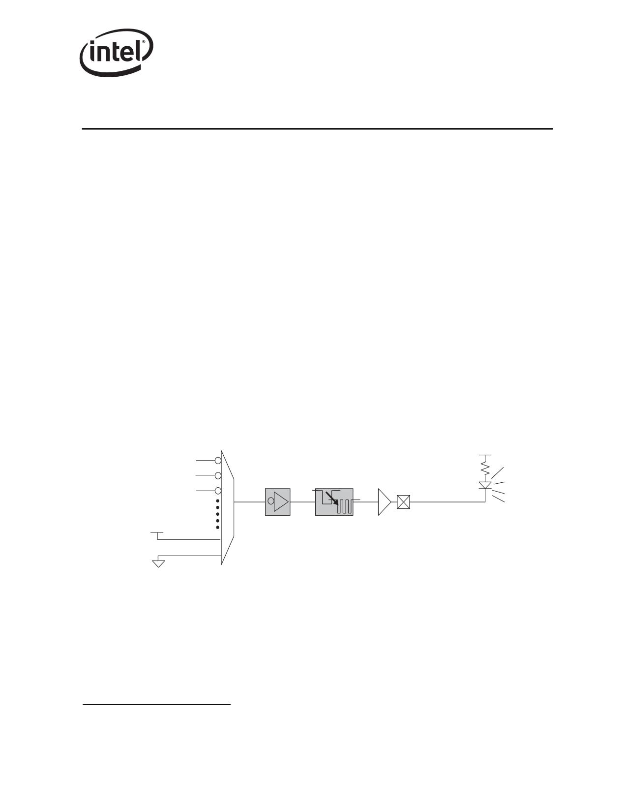
Configurable LED Outputs
10
10.1
Configurable LED Outputs1
The PCI/PCI-X Family of Gigabit Ethernet Controller’s MAC implements four output drivers
intended for driving external LED circuits. Each MAC’s four LED outputs can be individually
configured to select the particular event, state, or activity that is indicated on that output. In
addition, each LED can be individually configured for output polarity as well as for blinking vs.
non-blinking (steady-state) indication.
The configuration for LED outputs is specified via the LEDCTL register. In addition, the
hardware-default configuration for two of the LED outputs, LED0/LINK_UP# and LED2/
LINK100# can be specified via EEPROM fields, thereby supporting LED displays configurable to
a particular OEM preference.
10.1.1
Selecting an LED Output Source
Each of the four LED indications can be independently configured. The LEDCTL register MODE
field corresponding to each LED selects the expression generating the LED output. The LED
outputs are, by default, active low; it is assumed they are connected to the negative side (cathode)
of an external LED. They will, by default, output a low value upon the assertion of the event (such
as COLLISION) or state (such as LINK1000#) selected. Note that the active sense of the LED
outputs can be inverted). See Section 10.1.2 for details.
LINK_UP
ACTIVITY
COLLISION
EXTERNAL
LED
(OPTIONAL)
(OPTIONAL)
LED
POLARITY
BLINK
OUTPUT
VCC/LED_OFF
INVERSION
CONTROL
DRIVER
CIRCUIT
GND/LED_ON
Figure 10-1. Selecting an LED Output Source
1.
Section 10 does not apply to the 82544GC/EI.
183
Configurable LED Outputs
LED outputs can be based on the following expressions:
• LINK_UP is asserted while link of any speed is maintained
• LINK_10 indicates link at 10 Mbps
• LINK_100 indicates link at 100 Mbps
• LINK_1000 indicates link at 1000 Mbps
• LINK_100/1000 indicates link at either 100 or 1000 Mbps
• LINK_10/1000 indicates link at either 10 or 1000 Mbps
• ACTIVITY is asserted when link is established and packets are being transmitted or received
• LINK/ACTIVITY is asserted when link is established but there is NO transmit or receive
activity
• COLLISION is asserted each time a collision is observed
• PAUSED is asserted while the Ethernet controller’s transmitter is paused due to flow control
• PCIX_MODE is asserted when the Ethernet controller is in PCI-X mode (versus PCI mode)
• FULL_DUPLEX is asserted when the link is configured for full duplex operation
• BUS_SPEED is asserted in PCI 66 MHz or PCI-X 133 MHz configurations (high-speed
operation)
• BUS_SIZE is asserted in 64-bit PCI or PCI-X configurations
• LED_ON is always asserted (low); LED_OFF is always deasserted (high)
10.1.2
Polarity Inversion
The LEDCTL.IVRT field enables the selected LED source to be optionally inverted. This can be
used to drive external circuitry where an active high indication of one of the selectable states/
events is required (such as multi-color LED circuits).
Note:
Polarity inversion (LEDCTL.IVRT = 1b) and blinking (LEDCTL.BLINK = 1b) at the same time
for a given LED is not recommended. Introducing additional polarity inversion on a selected state/
event while blink-control is also enabled can produce nonsensical LED behavior (such as blinking
LED’s during periods of NO activity or when link is down).
10.1.3
Blink Control
Each LED’s output circuitry also includes a blink-control circuit that can additionally be enabled.
The blink control circuitry turns its output sequentially on (low) for 200 ms, then off for another
200 ms, each time its input is active/asserted. The LEDCTL.BLINK field controls whether a blink
circuit is enabled for an LED output.
The blink control is especially useful for ensuring that certain brief events, such as momentary
ACTIVITY or COLLISION events, cause LED transitions which are sufficiently visible to a
human eye. The circuit re-evaluates after each on/off blink cycle, ensuring a continuous blink
pattern throughout periods of continuous event/state assertion (such as heavy ACTIVITY periods
or long PAUSED times).
184
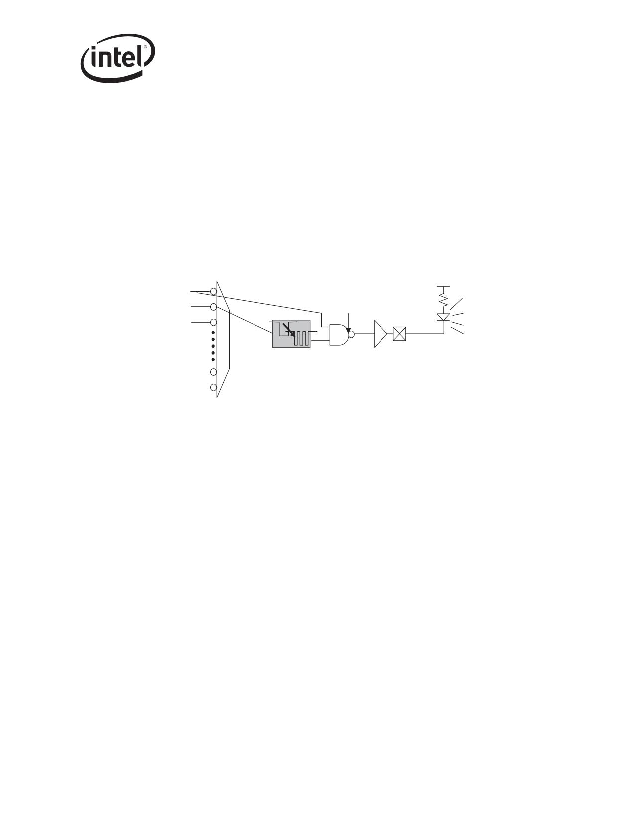
Configurable LED Outputs
Note: It is especially important to note with respect to the blink-control circuit that:
• the blink circuit, when enabled, exists as the LAST stage of the LED circuitry, after any
(optional) signal inversion
• the blink sequence occurs when the circuit input is asserted low
As a result, it is possible to select combinations of IVRT and BLINK which do not make sense or
produce unexpected results, such as examples previously noted. It is recommended that BLINK
only be selected for indicating ACTIVITY, COLLISION, PAUSED, or the combination LINK/
ACTIVITY signal. events/states, and that IVRT = 0b when blink is selected.
Note: Selecting the LEDCTL.MODE = LINK/ACTIVITY with BLINK = 1b selects a unique LED
output expression (this configuration is meaningful ONLY when IVRT inversion is disabled). In
this configuration, the LED is off (output high) if there is no LINK, on if there is LINK but no
ACTIVITY, and blinking if there is LINK with ACTIVITY.
LINK_UP
(LINK & NO ACTIVITY)
TOGGLING DURING ACTIVITY
ACTIVITY
EXTERNAL
BLINK
LED
LED
CONTROL
OUTPUT
CIRCUIT
DRIVER
Figure 10-2. Blink Control
185
Configurable LED Outputs
Note: This page is intentionally left blank.
186
PHY Functionality and Features
11
11.1
Auto-Negotiation
Auto-Negotiation between the PCI/PCI-X Family of Gigabit Ethernet Controllers and its link
partner is performed by the PHY. Under normal, expected operating conditions, the MAC
automatically establishes common speed and duplex settings via the PHY. This section details PHY
configuration features involved in the auto-negotiation process.
11.1.1
Overview
Auto-Negotiation by the PHY is initiated upon any of the following conditions:
• Power-up reset (copper and fiber)
• PHY detects loss of link (copper and fiber)
• PHY detects re-appearance of energy on the link (copper and fiber)
• MAC control of PHY power-management is enabled (CTRL.EN_PHY_PWR_MGMT = 1b
and MAC transitions to low power state (D3) where continued PHY operation required for
wakeup/manageability (copper and fiber)
• PHY hardware reset asserted using the MAC CTRL.PHY_RST bit (copper only)
• PHY soft-reset initiated via the PHY Control Register (bit 15, copper only)
• Explicit Auto-Negotiation Re-Start initiated via the PHY Control Register (bit 9, copper only)
• Explicit transition of PHY from internal IEEE power-down to normal mode via the PHY
Control Register (bit 11, copper only)
• Explicit transition of PHY from internal IEEE power-down to normal mode via the PHY
Control Register by setting CTRL.LRST = 1 and TXCW.ANE = 1 (fiber only)
Hardware defaults for the PHY configurations enable the PHY to advertise its full 1000BASE-T
and 1000BASE-X capability, and to auto-negotiate to the best possible operation1 without any
software intervention required. If the remote device does not have Auto-Negotiation capability, the
Ethernet controller PHY uses the parallel detect function to determine the speed of the remote
device for 100BASE-TX and 10BASE-T modes. Under certain circumstances, it might be
desirable to configure auto-negotiation options to restrict certain behavior. For example, operate in
half-duplex mode only.2
Note:
Any PHY auto-negotiation options configured by software are only persistent while the LAN
power (indicated by LAN_PWR_GOOD) remains available. Following a complete loss of power,
the PHY reverts to auto-negotiation using its hardware-defaults.
1.
1000 half-duplex not supported.
2.
TXCW and RXCW registers are used for fiber auto-negotiation advertising. For fiber, the MAC can be forced to 1000 full-duplex when
connected to a non-auto-negotiating fiber switch.
187
PHY Functionality and Features
11.1.2
Next Page Exchanges
If 1000BASE-T mode is advertised, then the Ethernet controller PHY automatically sends the
appropriate next pages to advertise the capability and negotiate master/slave mode of operation. If
a developer does not want to transmit additional next pages, the next page bit (PCI-Config Register
bit 15) can be set to 0b and the software need take no further action.
If next pages in addition to the ones required for 1000BASE-T are needed, then the software can
set Auto-Negotiation Expansion Register bit 15 to 1b, and send and receive additional next pages
via the Next Page Transmit Register (NPT) and Link Partner Next Page Register (LPN),
respectively. The PHY stores the previous results from the Link Partner Next Page Register (LPN)
in internal registers so that new next pages can overwrite the Link Partner Next Page Register
(LPN).
Note:
1000BASE-T next page exchanges are automatically handled without any software intervention,
regardless of whether or not additional next pages are sent.
11.1.3
Register Update
Changes to PHY Control Register bits 6, 8, 12, and 13, and PHY Specific Control Register bits 3,
4, 6:5, 9:8 and 11, do not take effect unless one of the following takes place (copper only):
• PHY soft reset (PHY Control Register bit 15)
• Restart Auto-Negotiation (PHY Control Register bit 9)
• Transition of PHY from IEEE power-down to normal operation (PHY Control Register bit 11)
• The link goes down
To enable or disable Auto-Negotiation, PHY Control Register bit 12 should be changed
simultaneously with either PHY Control Register bits 15 or 9. For example, to disable Auto-
Negotiation and force 10BASE-T half-duplex mode, the PHY Control Register should be written
with 8000h.
To disable Auto-Negotiation (fiber only), set TXCW.ANE = 0.
The Auto-Negotiation Expansion Register and the 1000BASE-T Control Register are internally
latched once every time the Auto-Negotiation enters the Ability Detect state in the arbitration state
machine. As a result, a write to the Auto-Negotiation Expansion Register or the 1000BASE-T
Control Register has no effect once the PHY begins to transmit Fast Link Pulses (FLPs). This
guarantees that sequences of FLPs transmitted are consistent with one another.
The Next Page Transmit Register is treated similarly to the Auto-Negotiation Expansion Register
and the 1000BASE-T Control Register during additional next page exchanges.
188

PHY Functionality and Features
11.1.4
Status
Once the PHY completes auto-negotiation, it updates the various statuses in the PHY Status
Register, Link Partner Ability Register (Base Page), Auto-Negotiation Expansion Register, and
1000BASE-T Status Register. For 1000BASE-T operation, the Auto-Negotiation Expansion
Register and the Link Partner Ability Register (Base Page) are updated. Speed, duplex, page
received, and Auto-Negotiation completion statuses are also available in the PHY Specific Status
Register (PSTATUS) and the PHY Interrupt Status Register (PINTS).
For fiber, the CTRL.STATUS register will reflect link status.
Assuming normal MAC configuration, the MAC status register STATUS reports bits SPEED, FD
(duplex/half indication), and LU (link up status) shortly after the PHY (or MAC, for fiber)
completes auto-negotiation.
11.2
MDI/MDI-X Crossover (copper only)
The Ethernet controller PHY automatically determines whether or not it needs to cross over
between pairs as shown in the following table so that an external crossover cable is not required. If
the PHY interoperates with a device that cannot automatically correct for crossover, the Ethernet
controller PHY makes the necessary adjustment prior to commencing Auto-Negotiation. If the
PHY operates with a device that implements MDI/MDI-X crossover, a random algorithm as
described in IEEE 802.3 clause 40.4.4 determines which device performs the crossover.
When the Ethernet controller PHY interoperates with legacy 10BASE-T devices that do not
implement Auto-Negotiation, the PHY follows the same algorithm as described above since link
pulses are present. However, when interoperating with legacy 100BASE-TX devices that do not
implement Auto-Negotiation (link pulses are not present), the Ethernet controller PHY uses signal-
detection to determine whether to crossover.
Auto MDI/MDI-X crossover is the default hardware configuration, but can be disabled via the
PHY Specific Control Register bits 6:5 (PSCON).
The pin mapping in MDI/MDI-X modes are as follows:
Pin
MDI
MDIX
1000BASE-T
100BASE-TX
10BASE-T
1000BASE-T
100BASE-TX
10BASE-T
MDI[0]+/-
BI_DA +/-
TX +/-
TX +/-
BI_DB +/-
RX +/-
RX +/-
MDI[1]+/-
BI_DB +/-
RX +/-
RX +/-
BI_DA +/-
TX +/-
TX +/-
MDI[2]+/-
BI_DC +/-
unused
unused
BI_DD +/-
unused
unused
MDI[3]+/-
BI_DD +/-
unused
unused
BI_DC +/-
unused
unused
189
PHY Functionality and Features
11.2.1
Polarity Correction (copper only)
The Ethernet controller PHY automatically corrects for polarity errors on the receive pairs in
1000BASE-T and 10BASE-T modes. In 100BASE-TX mode, the polarity does not matter.
In 1000BASE-T mode, receive polarity errors are automatically corrected based on the sequence of
the symbols. Once the descrambler is locked, the polarity is also locked on all pairs. The polarity
becomes unlocked only when the receiver loses lock.
11.2.2
10/100 Downshift (82540EP/EM Only)
Gigabit speed operation requires a 4-pair cable to operate. Some existing cables have only two
pairs. Other cables might have 4 pairs, but one might be broken, leaving three working pairs. Over
two or three pairs, two gigabit link partners might be able to successfully auto-negotiate 1000
Mbps speed, but then be unable to achieve link.
The downshift feature enables the 82540EP/EM PHY to auto-negotiate with another gigabit link
partner using a two or three pair cable and downshift to link at 100 Mbps or 10 Mbps, whichever is
the highest speed below gigabit that the link partner is capable of.
By default, downshift is turned on. Refer to Table 13-39 to disable the downshift feature.
190
PHY Functionality and Features
11.3
Cable Length Detection (copper only)
In 100/1000 Mbps operation, the Ethernet controller PHY attempts to indicate the approximate
length of the CAT 5 cable attached. The estimated cable length is reported as one of the following
ranges:
• <= 50 m
• 50 - 80 m
• 80 - 110 m
• 110 - 140 m
• >= 140 m
The estimated cable length can be obtained by reading the PHY Specific Status Register bits 9:7.
11.4
PHY Power Management (copper only)
The Ethernet controller PHY supports power-management based on either link status, MAC
power-state, or both. During link-down states, the PHY utilizes its energy-detection capabilities to
consume the least amount of power while still being capable of resuming link-up automatically. the
Ethernet controller can be configured to automatically reduce PHY power during certain MAC D3
states by re-negotiating a low-speed link (the default behavior, but this can be disabled).
11.4.1
Link Down - Energy Detect (copper only)
When the link is operational and the Ethernet controller PHY detects loss of link, it initiates an
Auto-Negotiation session. Failing to re-establish link via auto-negotiation, the PHY reverts to an
Energy Detect power-down state. Following link loss, the PHY monitors receive energy on the
wire. If the PHY detects energy on the wire, it starts to initiate Auto-Negotiation sending FLPs for
five seconds. If at the end of five seconds the Auto-Negotiation has not completed, then the PHY
stops sending FLPs and returns to monitoring receive energy. While monitoring receive energy, the
PHY sends out a single 10 Mbps NLP (Normal Link Pulse) every one second in an attempt to wake
up a connected device.
The above behavior is considered to be an advanced Energy-Detect (Energy Detect+) mode of
PHY operation. The PHY can also be configured for a regular Energy Detect mode, which behaves
similarly, except does not send out NLPs while monitoring receive energy. In this configuration,
the Ethernet controller PHY can be woken by a connected device, but does not wake up the
connected device itself.
The PHY Specific Control Register bits 9 and 8 described in Section 13.4.7.1.13 are used to
configure the specific Energy-Detect mode of behavior for the PHY.
191
PHY Functionality and Features
11.4.2
D3 State, No Link Required (copper only)
Each time the MAC transitions to a D3 or D0u power-state with no link required (wakeup disabled
and no manageability enabled), the PHY enters its IEEE power-down mode, consuming the least
amount of power possible. When powered-down, the PHY does not perform any form of Energy
Detection, and does not generate any energy (NLPs) on the wire itself.
MAC transitions back to D0 power-states, either through explicit system/software mechanisms or
by hardware reset operations, return the PHY back to a functional power-state. This will also re-
initiate an auto-negotiation attempt advertising all speeds possible (10/100/1000 Mbps)1, reverting
to an Energy Detect state if unsuccessful in establishing link-up.
11.4.3
D3 Link-Up, Speed-Management Enabled (copper only)
If the MAC is configured for PHY power management (CTRL.EN_PHY_PWR_MGMT = 1b) and
the PHY is linked at 1000 Mbps, then upon MAC transitions to D3 or D0u power-states where link
IS required (either wakeup or manageability are enabled), the PHY re-initiates an Auto-
Negotiation operation, advertising only 10/100 Mbps capability. This results in D3 operation at a
lower-speed link and a reduced power level.
If a wakeup, management operation, or other system event causes the MAC to revert to fully-
operational D0 state, the PHY initiates another Auto-Negotiation operation, advertising all 10/100/
1000 Mbps speed capability, in order to return to maximum-speed operation.
11.4.4
D3 Link-Up, Speed-Management Disabled (copper only)
If the MAC is configured for no PHY power management (CTRL.EN_PHY_PWR_MGMT = 0b),
and the MAC transitions to D3 power-states where link is required for either wakeup or
manageability, then the PHY simply remains operational at its current line speed, without initiating
a new Auto-Negotiation operation. This configuration is not recommended, since D3 power
consumption at 1000 Mbps exceeds 20 mA Vaux.
1.
Half duplex not supported.
192
PHY Functionality and Features
11.5
Initialization
Note: Section 11.5 through Section 11.14 apply only to the 82541xx and 82547GI/EI Ethernet
controllers.
At power-up or reset, the PHY core performs the initialization as shown in Figure 11-1. The
software driver has access to the PHY register 0d, bits 15 and 11 for PHY reset and PHY Power
Down control, respectively.
Power-up
or
Reset
Read H/W
Control
Interface
Initialize
MDIO
Registers
Pass control
to
MDIO Interface
Figure 11-1. PHY Initialization Sequence
11.5.1
MDIO Control Mode
In the MDIO Control mode, the PHY uses the Hardware Control Interface to set up initial (default)
values of the MDIO registers. Once initial values are set, bit control reverts to the MDIO interface.
The PHY can perform some low level initializations such as DSP configuration based upon
EEPROM settings. The details of those initializations are reserved.
193
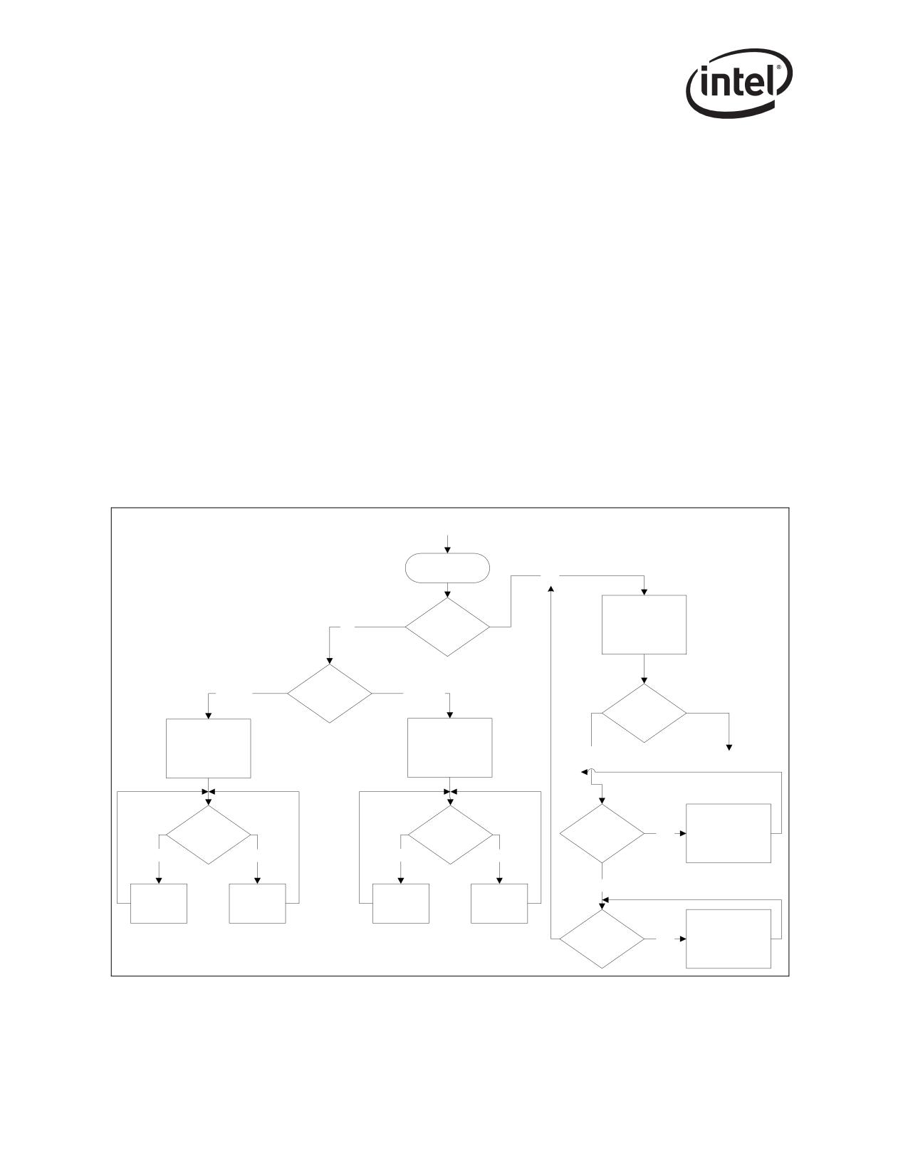
PHY Functionality and Features
11.6
Determining Link State
The PHY and its link partner determine the type of link established through one of three methods:
• Auto-Negotiation
• Parallel Detection
• Forced Operation
Auto-Negotiation is the only method allowed by the 802.3ab standard for establishing a
1000BASE-T link, although forced operation could be used for test purposes. For 10/100 links, any
of the three methods can be used. The sections that follow discuss each in greater detail.
Figure 11-2 provides an overview of link establishment. First the PHY checks if Auto-Negotiation
is enabled. By default, the PHY supports Auto-Negotiation (PHY register 0, bit 12). If not, the
PHY forces operation as directed. If Auto-Negotiation is enabled, the PHY begins transmitting
Fast Link Pulses (FLPs) and receiving FLPs from its link partner. If FLPs are received by the PHY,
Auto-Negotiation proceeds. It also can receive 100BASE-TX MLT3 and 10BASE-T Normal Link
Pulses (NLPs). If either MLT3 or NLPs are received, it aborts FLP transmission and immediately
brings up the corresponding half-duplex link.
Power-Up, Reset,
Link Failure
Start
Yes
A/N
No
Enabled
Send FLP
?
Speed
0 = 10M
0.13
1 = 100M
No
Yes
?
Detect
FLP
Send NLP
Send IDLES
Parallel
Auto
Detect
Negotiate
Detect
Detect
100M
Detect
10Mbps
10Mbps
Yes
Half-Duplex
IDLES
?
?
Link
No
Yes
No
Yes
No
Take
Take
Link
Link
Link
Link
Down
Up
Down
Up
10M
Detect
Yes
Half-Duplex
NLP
Link
Figure 11-2. Overview of Link Establishment
194

PHY Functionality and Features
11.6.1
False Link
When the PHY is first powered on, reset, or encounters a link down state, it must determine the line
speed and operating conditions to use for the network link.
The PHY first checks the MDIO registers (initialized via the Hardware Control Interface or written
by software) for operating instructions. Using these mechanisms, programmers can command the
PHY to do one of the following:
• Force twisted-pair link operation to:
- 1000T Full Duplex
- 1000T Half Duplex
- 100TX, Full Duplex
- 100TX, Half Duplex
- 10BASE-T, Full Duplex
- 10BASET, Half Duplex
• Allow Auto-Negotiation/parallel-detection.
In the first six cases (forced operation), the PHY immediately begins operating the network
interface as commanded. In the last case, the PHY begins the Auto-Negotiation/parallel-detection
process.
11.6.2
Forced Operation
Forced operation can be used to establish 10 and 100 links, and 1000 links for test purposes. In this
method, Auto-Negotiation is disabled completely and the link state of the PHY is determined by
PHY register 0d.
Note:
When speed is forced, the MDI/MDI-X crossover feature is not functional.
In forced operation, the programmer sets the link speed (10, 100, or 1000) and duplex state (full or
half). For Gigabit (1000) links, the programmer must explicitly designate one side as the Master
and the other as the Slave. Table 10-1 summarizes link establishment procedures.
Table 10-1. Determining Duplex State Via Parallel Detection
Configuration
Result
Both sides set for Auto-Negotiate.
Link is established via Auto-Negotiation.
Both sides set for forced operation.
No problem as long as duplex settings match.
One side set for Auto-Negotiation and the other for
Link is established via parallel detect.
forced, half-duplex.
Link is established; however, sides disagree, resulting
One side set for Auto-Negotiation and the other for
in transmission problems. Forced side is full-duplex,
forced full-duplex.
Auto-Negotiation side is half-duplex.
195
PHY Functionality and Features
11.6.3
Auto Negotiation
The PHY supports the IEEE 802.3u Auto-Negotiation scheme with next page capability. Next Page
exchange uses PHY register 7d to send information and PHY register 8d to receive them. Next
Page exchange can only occur if both ends of the link advertise their ability to exchange Next
Pages.
11.6.4
Parallel Detection
Parallel detection can only be used to establish 10 and 100 links. It occurs when the PHY tries to
negotiate (transmit FLPs to its link partner), but instead of sensing FLPs from the link partner, it
senses 100BASE-TX MLT3 code or 10BASE-T Normal Link Pulses (NLPs) instead. In this case,
the PHY immediately stops Auto-Negotiation (terminates transmission of FLPs) and immediately
brings up whatever link corresponds to what it has sensed (MLT3 or NLPs). If the PHY senses both
of the technologies together, a parallel detection fault is detected and the PHY continues sending
FLPs
With parallel detection, it is impossible to determine the true duplex state of the link partner, and
the IEEE standard requires the PHY to assume a half-duplex link. Parallel detection also does not
allow exchange of flow-control ability (PAUSE and ASM_DIR) or Master/Slave relationship
required by 1000BASE-T. For this reason, parallel detection cannot be used to establish Gigabit
Ethernet links.
11.7
Link Criteria
Once the link state is determined-via Auto-Negotiation, parallel detection or forced operation-
the PHY and its link partner bring up the link.
11.7.1
1000BASE-T
For 1000BASE-T links, the PHY and its link partner enter a training phase. They exchange idle
symbols and use the information gained to set their adaptive filter coefficients.
Either side indicates completion of the training phase to its link partner by changing the encoding
of the idle symbols it transmits. When both sides so indicate, the link is up. Each side continues
sending idle symbols whenever it has no data to transmit. The link is maintained as long as valid
idle, data, or carrier extension symbols are received.
11.7.2
100BASE-TX
For 100BASE-TX links, the PHY and its link partner immediately begin transmitting idle symbols.
Each side continues sending idle symbols whenever it has no data to transmit. The link is
maintained as long as valid idle symbols or data is received.
In 100Mbps mode, the PHY establishes a link whenever the scrambler becomes locked and
remains locked. Link will remain up unless the descrambler receives idles at less than a specified
rate.
196
PHY Functionality and Features
11.7.3
10BASE-T
For 10BASE-T links, the PHY and its link partner begin exchanging Normal Link Pulses (NLPs).
The PHY transmits an NLP every 16 ms, and expects to receive one every 10 to 20 ms. The link is
maintained as long as normal link pulses are received.
11.8
Link Enhancements
The PHY offers two enhanced link functions, each of which are discussed in the sections that
follow:
• SmartSpeed
• Flow Control
11.8.1
SmartSpeed
SmartSpeed is an enhancement to Auto-Negotiation that enables the PHY to react intelligently to
network conditions that prohibit establishment of a 1000BASE-T link, such as cable problems.
Such problems might enable Auto-Negotiation to complete, but then inhibit completion of the
training phase. Normally, if a 1000BASE-T link fails, the PHY returns to the Auto-Negotiation
state with the same speed settings indefinitely. With SmartSpeed enabled, after five failed attempts,
the PHY automatically downgrades the highest ability it advertises to the next lower speed: from
1000 to 100 to 10. Once a link is established, and if it is later broken, the PHY automatically
upgrades the capabilities advertised to the original setting.
11.8.1.1
Using SmartSpeed
SmartSpeed is enabled by setting PHY register 16d, bit 7 to 1b. When SmartSpeed downgrades the
PHY advertised capabilities, it sets bit 5 of PHY register 19. When link is established, its speed is
indicated in PHY register 17, bits 15:14. SmartSpeed automatically resets the highest-level Auto-
Negotiation abilities advertised, if link is established and then lost for more than two seconds.
11.8.2
Flow Control
Flow control enables congested nodes to pause traffic. MACs indicate their ability to implement
flow control during Auto-Negotiation.
The PHY transparently supports MAC-to-MAC advertisement of flow control through its Auto-
Negotiation process. Prior to Auto-Negotiation, the MAC indicates its flow control capabilities via
PHY register 4d, bit 10 (Pause) and PHY register 4d, bit 11 (ASM_DIR). After Auto-Negotiation,
the link partner’s flow control capabilities are indicated in PHY register 5d, bits 11:10.
197
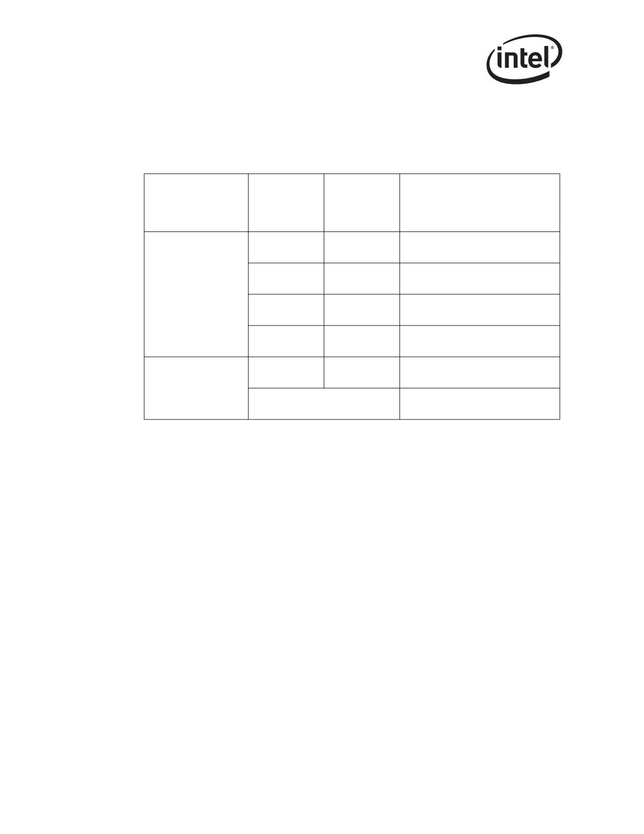
PHY Functionality and Features
Table 10-2 lists the intended operation for the various settings of ASM_DIR and Pause. This
information is provided for reference only; it is the responsibility of the MAC to implement the
correct function. The PHY merely enables the two MACs to communicate their abilities to each
other.
Table 10-2. Pause And Asymmetric Pause Settings
ASM_DIR Settings
Pause Setting -
Pause Setting -
Local
Local (PHY
Remote (PHY
(PHY Register 4d, Bit
Result
Register 4d, Bit
Register 5d, Bit
10) and Remote (PHY
9)
9)
Register 5d, Bit 10)
Symmetric - Either side can flow control
1b
1b
the other
Asymmetric - Remote can flow control
1b
0b
local only
Both ASM_DIR = 1b
Asymmetric - Local can flow control
0b
1b
remote
0b
0b
No flow control
Symmetric - Either side can flow control
1b
1b
the other
Either or both
ASM_DIR = 0b
Either or both = 0b
No flow control
11.9
Management Data Interface
The PHY supports the IEEE 802.3 MII Management Interface also known as the Management
Data Input/Output (MDIO) Interface. The MDIO interface consists of a physical connection to the
MAC, a specific protocol which runs across the connection, and a 16-bit MDIO register set.
PHY Registers 0d through 10d and 15d are required and their functions are specified by the IEEE
802.3 specification. Additional registers are included for expanded functionality.
11.10
Low Power Operation
The Ethernet controller can be get into a low-power state according to MAC control (Power
Management controls) or via PHY register 0d. In either power down mode, the Ethernet controller
is not capable of receiving or transmitting packets.
198
PHY Functionality and Features
11.10.1
Powerdown via the PHY Register
The PHY can be powered down using the control bit found in PHY register 0d, bit 11. This bit
powers down a significant portion of the port but clocks to the register section remain active. This
enables the PHY management interface to remain active during power-down. The power-down bit
is active high. When the PHY exits software power-down (PHY register 0d, bit 11 = 1b), it re-
initializes all analog functions, but retains its previous configuration settings.
11.10.2
Smart Power-Down
Smart Power-Down (SPD) is a link-disconnect capability applicable to all power management
states, and is intended for mobile applications. Smart powerdown combines a power saving
mechanism with the fact that link might disappear and resume.
SPD is enabled by PHY register 20d, bit 5 or by the SPD Enable bit in the EEPROM, and is
entered when the PHY detects link lost. Auto-Negotiation must also be enabled. While in the SPD
state, the PHY powers down circuits and clocks that are not required for detection of link activity.
The PHY is still able to detect link pulses (including parallel detect) and wake up to engage in link
negotiation. The PHY does not send link pulses (NLP) while in the SPD state. Register accesses
are still possible.
Connecting a member of the family to another system with the SPD feature can lead to link failures
if both ports are allowed to enter the SPD state.
11.11
1000 Mbps Operation
11.11.1
Introduction
This section provides an overview of 1000BASE-T functions, followed by discussion and review
of the internal functional blocks shown in Figure 11-3.
199
PHY Functionality and Features
MAC Interface
8
8
Side-stream
Trellis Viterbi
Scrambler /
Encoder/ Decoder
Descrambler
4
DSP
4
ECHO, NEXT,
4DPAM5
FEXT Cancellers
Encoder
AGC, A/D,
Pulse Shaper,
Timing Recovery
DAC, Filter
Hybrid
Line Driver
Line
Interface
Figure 11-3. 1000 Base-T PHY Functions Overview
200
PHY Functionality and Features
11.11.2
Transmit Functions
This section describes functions used when the Media Access Controller (MAC) transmits data
through the PHY and out onto the twisted-pair connection.
11.11.2.1
Scrambler
The scrambler randomizes the transmitted data. The purpose of scrambling is two fold:
1. Scrambling eliminates repeating data patterns from the 4DPAM5 waveform to reduce EMI.
2. Each channel (A, B, C, D) gets a unique signature that the receiver uses for identification.
The scrambler is driven by a Linear Feedback Shift Register (LFSR), which is randomly loaded at
power-up. The LFSR function used by the Master differs from that used by the Slave, giving each
direction its own unique signature. The LFSR, in turn, generates uncorrelated outputs. These
outputs randomize the inputs to the 4DPAM5 and Trellis encoders and randomize the sign of the
4DPAM5 outputs.
11.11.3
Transmit FIFO
The transmit FIFO re-synchronizes data transmitted by the MAC to the transmit reference used by
the PHY.
11.11.3.1
Transmit Phase-Locked Loop PLL
This function generates the 125 MHz timing reference used by the PHY to transmit 4DPAM5
symbols. When the PHY is the Master side of the link, the crystal input is the reference for the
transmit PLL. When the PHY is the Slave side of the link, the recovered receive clock is the
reference for the transmit PLL.
11.11.3.2
Trellis Encoder
The Trellis Encoder uses the two high-order bits of data and its previous output to generate a ninth
bit, which determines if the next 4DPAM5 pattern should be even or odd. This function provides
forward error correction and enhances the signal-to-noise (SNR) ratio by a factor of 6 dB.
11.11.3.3
4DPAM5 Encoder
The 4DPAM5 encoder translates 8B codes transmitted by the MAC into 4DPAM5 symbols. The
encoder operates at 125 Mhz, which is both the frequency of the MAC interface and the baud rate
used by 1000BASE-T.
Each 8B code represents one of 256 data patterns. Each 4DPAM5 symbol consists of one of five
signal levels (-2,-1,0,1,2) on each of the four twisted pair (A,B,C,D) representing 54 or 625
possible patterns per baud period. Of these, 113 patterns are reserved for control codes, leaving 512
patterns for data. These data patterns are divided into two groups of 256 even and 256 odd data
patterns. As a result, each 8B octet has two possible 4DPAM5 representations-one even and one
odd pattern.
201
PHY Functionality and Features
11.11.3.4 Spectral Shaper
This function causes the 4DPAM5 waveform to have a spectral signature that is very close to that
of the MLT3 waveform used by 100BASE-TX. This enables 1000BASE-T to take advantage of
infrastructure (cables, magnetics) designed for 100BASE-TX.
The shaper works by transmitting 75% of a 4DPAM5 code in the current baud period, and adding
the remaining 25% into the next baud period.
11.11.3.5 Low-Pass Filter
To aid with EMI, this filter attenuates signal components more than 180 Mhz. In 1000BASE-T, the
fundamental symbol rate is 125 Mhz.
11.11.3.6 Line Driver
The line driver drives the 4DPAM5 waveforms onto the four twisted-pair channels (A, B, C, D),
adding them onto the waveforms that are simultaneously being received from the link partner.
11.11.3.7 Transmit/Receive Flow
D0
D1
D2
D3
8
9
PAM-5
Trellis
4D
Scrambler
Encoded Output
Encoder
PAM-5
D4
to 4-Pair UPT Line
D5
D6
D7
Scrambler Polynomials:
1 + x13 + x33 (Master PHY Mode)
1 + x20 + x33 (Slave PHY Mode)
Figure 11-4. 1000BASE-T Transmit Flow And Line Coding Scheme
202
PHY Functionality and Features
D0
D1
D2
Polynomial
D3
8 bits
8 bits Descrambler
DSP
GMII
PAM-5
Receiver
D4
Encoded Input
from 4-Pair UTP Line
D5
D6
D7
Figure 11-5. 1000BASE-T Receive Flow
11.11.4
Receive Functions
This section describes function blocks that are used when the PHY receives data from the twisted
pair interface and passes it back to the MAC.
11.11.4.1
Hybrid
The hybrid subtracts the transmitted signal from the input signal, allowing the use of simple
100BASE-TX compatible magnetics.
11.11.4.2
Automatic Gain Control
The Automatic Gain Control (AGC) normalizes the amplitude of the received signal, adjusting for
the attenuation produced by the cable.
11.11.4.3
Timing Recovery
This function re-generates a receive clock from the incoming data stream which is used to sample
the data. On the Slave side of the link, this clock is also used to drive the transmitter.
11.11.4.4
Analog-to-Digital Converter
The Analog-to-Digital (ADC) function converts the incoming data stream from an analog
waveform to digitized samples for processing by the DSP core.
11.11.4.5
Digital Signal Processor
The Digital Signal Processor (DSP) provides per-channel adaptive filtering, which eliminates
various signal impairments including:
• Inter-symbol interference (equalization).
• Echo caused by impedance mismatch of the cable.
• Near-end crosstalk (NEXT) between adjacent channels (A, B, C, D).
203
PHY Functionality and Features
• Far-end crosstalk (FEXT)
• Propagation delay variations between channels of up to 120 ns.
• Extraneous tones that have been coupled into the receive path.
The adaptive filter coefficients are initially set during the training phase. They are continuously
adjusted (adaptive equalization) during operation through the decision-feedback loop.
11.11.4.6 Descrambler
The descrambler identifies each channel by its characteristic signature, removing the signature and
re-routing the channel internally. In this way, the receiver can correct for channel swaps and
polarity reversals. The descrambler uses the same base LFSR used by the transmitter on the other
side of the link.
The descrambler requires approximately 15 s. to lock, normally accomplished during the training
phase.
11.11.4.7 Viterbi Decoder/Decision Feedback Equalizer (DFE)
The Viterbi decoder generates clean 4DPAM5 symbols from the output of the DSP. The decoder
includes a Trellis encoder identical to the one used by the transmitter. The Viterbi decoder simulta-
neously looks at the received data over several baud periods. For each baud period, it predicts
whether the symbol received should be even or odd, and compares that to the actual symbol
received. The 4DPAM5 code is organized in such a way that a single level error on any channel
changes an even code to an odd one and vice versa. In this way, the Viterbi decoder can detect
single-level coding errors, effectively improving the Signal-To-Noise (SNR). When an error
occurs, this information is quickly fed back into the equalizer to prevent future errors.
11.11.4.8 4DPAM5 Decoder
The 4DPAM5 decoder generates 8B data from the output of the Viterbi decoder.
11.12
100 Mbps Operation
The MAC passes data to the PHY over the MII. The PHY encodes and scrambles the data, then
transmits it using MLT-3 for 100TX over copper. The PHY descrambles and decodes MLT-3 data
received from the network. When the MAC is not actively transmitting data, the PHY sends out
idle symbols on the line.
11.13
10 Mbps Operation
The PHY operates as a standard 10 Mbps transceiver. Data transmitted by the MAC as 4-bit nibbles
is serialized, Manchester-encoded, and transmitted on the MDI[0]+/- outputs. Received data is
decoded, de-serialized into 4-bit nibbles and passed to the MAC across the internal MII. The PHY
supports all the standard 10 Mbps functions.
204
PHY Functionality and Features
11.13.1
Link Test
In 10 Mbps mode, the PHY always transmits link pulses. If the Link Test Function is enabled, it
monitors the connection for link pulses. Once it detects 2 to 7 link pulses, data transmission is
enabled and remains enabled as long as the link pulses or data reception continues. If the link
pulses stop, the data transmission is disabled.
If the Link Test function is disabled, the PHY might transmit packets regardless of detected link
pulses. Setting PHY register 16d, bit 14 can disable the Link Test function.
11.13.2
10Base-T Link Failure Criteria and Override
Link failure occurs if Link Test is enabled and link pulses stop being received. If this condition
occurs, the PHY returns to the Auto-Negotiation phase if Auto-Negotiation is enabled. Setting
PHY register 16d, bit 14 disables the Link Integrity Test function, then the PHY transmits packets,
regardless of link status.
11.13.3
Jabber
If the MAC begins a transmission that exceeds the jabber timer, the PHY disables the Transmit and
loopback functions and asserts collision indication to the MAC. The PHY automatically exits
jabber mode after 250-750 ms. This function can be disabled by setting PHY register 16d, bit 10 to
1b.
11.13.4
Polarity Correction
The PHY automatically detects and corrects for the condition where the receive signal
(MDI_PLUS[0]/MDI_MINUS[0]) is inverted. Reversed polarity is detected if eight inverted link
pulses, or four inverted end-of-frame markers, are received consecutively. If link pulses or data are
not received for 96-130 ms, the polarity state is reset to a non-inverted state.
11.13.5
Dribble Bits
The PHY device handles dribble bits for all of its modes. If between one to four dribble bits are
received, the nibble is passed across the interface. The data passed across is padded with 1b’s if
necessary. If between five to seven dribble bits are received, the second nibble is not sent onto the
internal MII bus to the MAC. This ensures that dribble bits between 1-7 do not cause the MAC to
discard the frame due to a CRC error.
11.14
PHY Line Length Indication
The PHY has a mechanism to deliver coefficient data for use in measuring cable length. If this
capability is required, please contact your Intel representative for details.
205
PHY Functionality and Features
Note: This page is intentionally left blank.
206
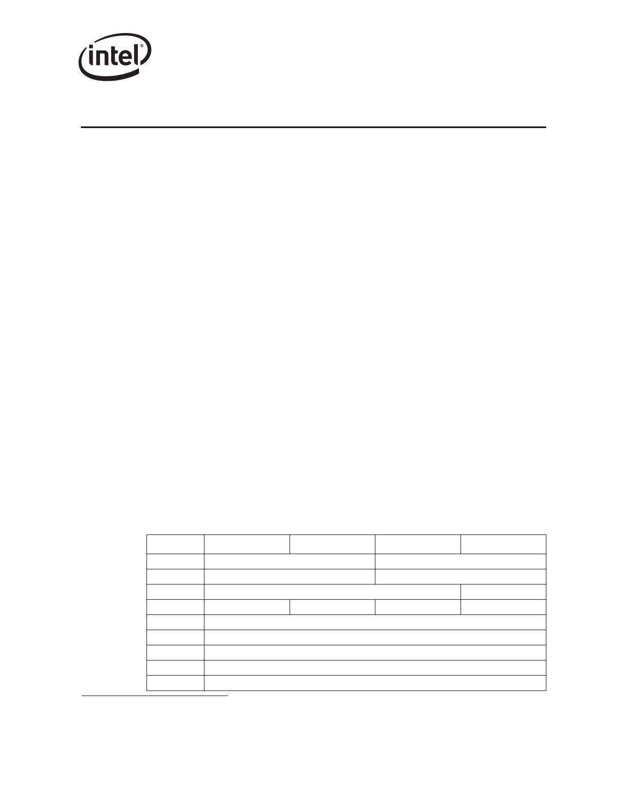
Dual Port Characteristics
12
12.1
Introduction1
The 82546GB/EB architecture includes two instances of both the MAC and PHY (see Figure 2-1).
With both MAC/PHY pairs operating, the Ethernet controller appears as a multi-function PCI
device containing two identically-functioning devices. To avoid confusion, each MAC (when
combined with either an internal PHY or an internal TBI transceiver/SerDes) is referred to as
“LANx”, where x = “A” or x = “B” to refer to each logical LAN device (LAN A or LAN B).
This section details specific features common to each MAC or PHY, resources/interfaces for which
dedicated independent hardware/software interfaces exists for each LAN, as well as resources
which are shared by both LAN devices.
The Ethernet controller normally appears to the system as a single, multi-function PCI device. It
provides the ability to selectively disable one of the internal LAN functions, thereby allowing it to
appear to the system as a single-function, single-LAN device. The mechanisms for controlling this
behavior and the resulting appearance to the system are described in Section 12.5 entitled, “LAN
Disable”.
12.2
Features of Each MAC
The Ethernet controller is designed to have the capability to appear as two independent instances of
a gigabit controller. The following section details major features that can be considered to be
distinct features available to each Ethernet controller MAC independently.
12.2.1
PCI/PCI-X interface
The Ethernet controller contains a single physical PCI/PCI-X interface. The Ethernet controller is
designed so that each of the logical LAN devices (LAN A and LAN B) appear as a distinct PCI/
PCI-X bus device implementing, along with other registers, the following PCI device header space:
Byte Offset
Byte 0
Byte 1
Byte 2
Byte 3
0h
Device ID
Vendor ID
4h
Status Register
Command Register
8h
Class Code 020000h
Revision ID 00h
Ch
BIST 00h
Header Type 00h
Latency Timer
Cache Line Size
10h
Base Address 0
14h
Base Address 1
1h8
Base Address 2
1Ch
Base Address 3
20h
Base Address 4
1.
Section 12 only applies to the 82546GB/EB.
207
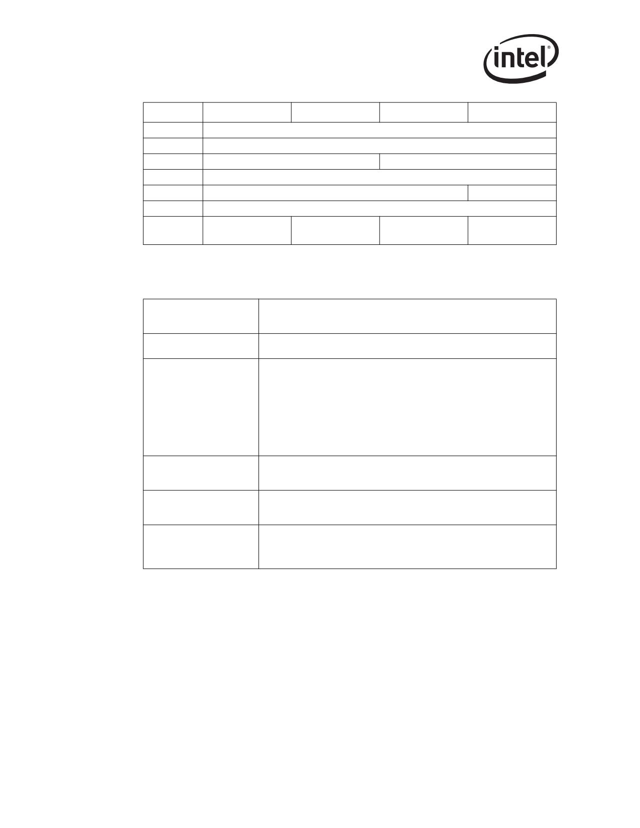
Dual Port Characteristics
Byte Offset
Byte 0
Byte 1
Byte 2
Byte 3
24h
Base Address 5
28h
Cardbus CIS Pointer (not used)
2Ch
Subsystem ID
Subsystem Vendor ID
30h
Expansion ROM Base Address
34h
Reserved
Cap_Ptr
38h
Reserved
Min_Grant
Interrupt Pin
Interrupt Line
3Ch
Max_Latency 00h
FFh
01h or 00h)
00h
Many of the fields of the PCI header space contain hardware default values that are either fixed or
can be overridden using EEPROM, but cannot be independently specified for each logical LAN
device. The following fields are considered to be common to both LAN devices:
The Vendor ID of the Ethernet controller can be specified via EEPROM, but
Vendor ID
only a single value can be specified. The value is reflected identically for both
LAN devices.
The revision number of the Ethernet controller is reflected identically for both
Revision
LAN devices.
This field indicates if a device is single function or multifunction. The value
reflected in this field is reflected identically for both LAN devices, but the actual
value reflected depends on LAN Disable configuration.
When both Ethernet controller LAN ports are enabled, both PCI headers return
Header Type
80h in this field, acknowledging being part of a multi-function device. LAN A
exists as device “function 0”, while LAN B exists as device “function 1”.
If one of the LAN ports is disabled, then only a single-function device is
indicated (this field returns a value of 00h), and the LAN exists as device
“function 0”.
The Subsystem ID of the Ethernet controller can be specified via EEPROM,
Subsystem ID
but only a single value can be specified. The value is reflected identically for
both LAN devices.
The Subsystem Vendor ID of the Ethernet controller can be specified via
Subsystem Vendor ID
EEPROM, but only a single value can be specified. The value is reflected
identically for both LAN devices.
Class Code,
Cap_Ptr,
These fields reflect fixed values that are constant values reflected for both LAN
Max Latency,
devices.
Min Grant
208

Dual Port Characteristics
The following fields are implemented unique to each LAN device:
The Device ID reflected for each LAN device can be independently specified
Device ID
via EEPROM.
Command,
Each LAN device implements its own command/status registers.
Status
Each LAN device implements these registers uniquely. The system should
Latency Timer,
program these fields identically for each LAN to ensure consistent behavior
Cache Line Size
and performance of each device.
Memory BAR,
Flash BAR,
Each LAN device implements its own Base Address registers, allowing each
IO BAR,
device to claim its own address region(s).
Expansion ROM BAR
Each LAN device independently indicates which interrupt pin (INTA# or INTB#)
is used by that Ethernet controller’s MAC to signal system interrupts. The
Interrupt Pin
value for each LAN device can be independently specified via EEPROM, but
only if both LAN devices are enabled.
12.2.2
MAC Configuration Register Space
All device control/status registers detailed in Section 13.4, Main Register Descriptions, are
implemented per-LAN device. Each LAN device can be accessed using memory or I/O cycles,
depending on the specific BAR setting(s) established for that LAN device.
Register accesses to each MAC instance are independent. In PCI bus operation, a register access to
one LAN which is retried as a delayed-read requires subsequent accesses to that LAN to retry the
read identically until complete. An outstanding delayed-read for one LAN device does not impact
the Ethernet controller’s ability to accept a register access to the other LAN. Similarly, in PCI-X
bus operation, and register access resulting in a split & split-completion by one LAN device in no
way prevents the other LAN device from accepting and servicing (or splitting) an access to its
register space.
12.2.3
SDP, LED, INT# output
Each LAN device provides an independent set of LED outputs and software-programmable I/O
pins (SDP). Four LED outputs and four SDP pins are provided per LAN device. These pins and
their function are bound to a specific LAN device (eight SDP pins cannot be associated with a
single LAN device, for example).
Each LAN device can use a dedicated pin for signalling interrupts to the system. Two pins, INTA#
and INTB#, exist on the Ethernet controller to signal interrupts by the different LAN devices. The
specific pin used by each LAN is configurable when both LAN devices are enabled.
209

Dual Port Characteristics
12.3
Shared EEPROM
The Ethernet controller uses a single EEPROM device to configure hardware default parameters
for both LAN devices, including Ethernet Individual Addresses (IA), LED behaviors, receive
packet-filters for manageability and wakeup capability, etc. Certain EEPROM words are used to
specify hardware parameters which are LAN device-independent (such as those that affect circuits
behavior). Other EEPROM words are associated with a specific LAN device. LAN A and LAN B
accesses the EEPROM to obtain their respective configuration settings.
12.3.1
EEPROM Map
The EEPROM map identifies those words configuring both LAN devices or the entire Ethernet
controller component as “LAN A/B Shared”. Those words configuring a specific LAN device
parameters are identified as either “LAN A” or “LAN B”.
The following EEPROM words warrant additional notes specifically related to dual-LAN support:
The EEPROM specifies the IA associated with the LAN A device and used as
the hardware default of the Receive Address Registers for that device. The
Ethernet Address (IA)
hardware-default IA for the LAN B device is automatically determined by the
(LAN A/B shared)
same EEPROM word, and is set to the value of {Ethernet IA LAN A with its
least significant bit inverted}.
Initialization Control 1,
These EEPROM words specify hardware-default values for parameters that
apply a single value to both LAN devices, such as link configuration
Initialization Control 2
parameters required for auto-negotiation, wakeup settings, PCI/PCI-X bus
(LAN A/B shared)
advertised capabilities, etc.
This EEPROM word configures default values associated with each LAN
device’s hardware connections, including which link mode (internal PHY,
external TBI SerDes) is used with this LAN device. Because a separate
Initialization Control 3
EEPROM word configures the defaults for each LAN, extra care must be taken
(LAN A, LAN B unique)
to ensure that the EEPROM image does not specify a resource conflict. For
example, multiple LAN devices both attempting to utilize the external TBI
transceiver interface at once.
This EEPROM word configures manageability parameters. Note that this word
controls whether an internal ASF controller is enabled/disabled for this LAN,
and whether the SMBus is enabled/disabled for this LAN. Extra care must be
Management Control
taken to ensure that the EEPROM image does not specify a resource conflict -
if an internal ASF controller is being used, it can only be enabled for a single
LAN device. The SMBus can only be enabled for a single LAN device.
12.3.2
EEPROM Arbitration
The Ethernet controller uses a single EEPROM to store hardware configuration words for both
LAN devices. The words used by each specific LAN device are noted in the EEPROM map. Each
LAN device obtains its EEPROM configuration parameters by performing its own independent
EEPROM read. Each LAN device reads the entire EEPROM image, verifying the EEPROM
signature, and applying the word(s) appropriate for the specific LAN device. The Ethernet
controller internally arbitrates between EEPROM access by the two LAN devices, to ensure that
each device is able to perform a complete, uninterrupted EEPROM read sequence.
210
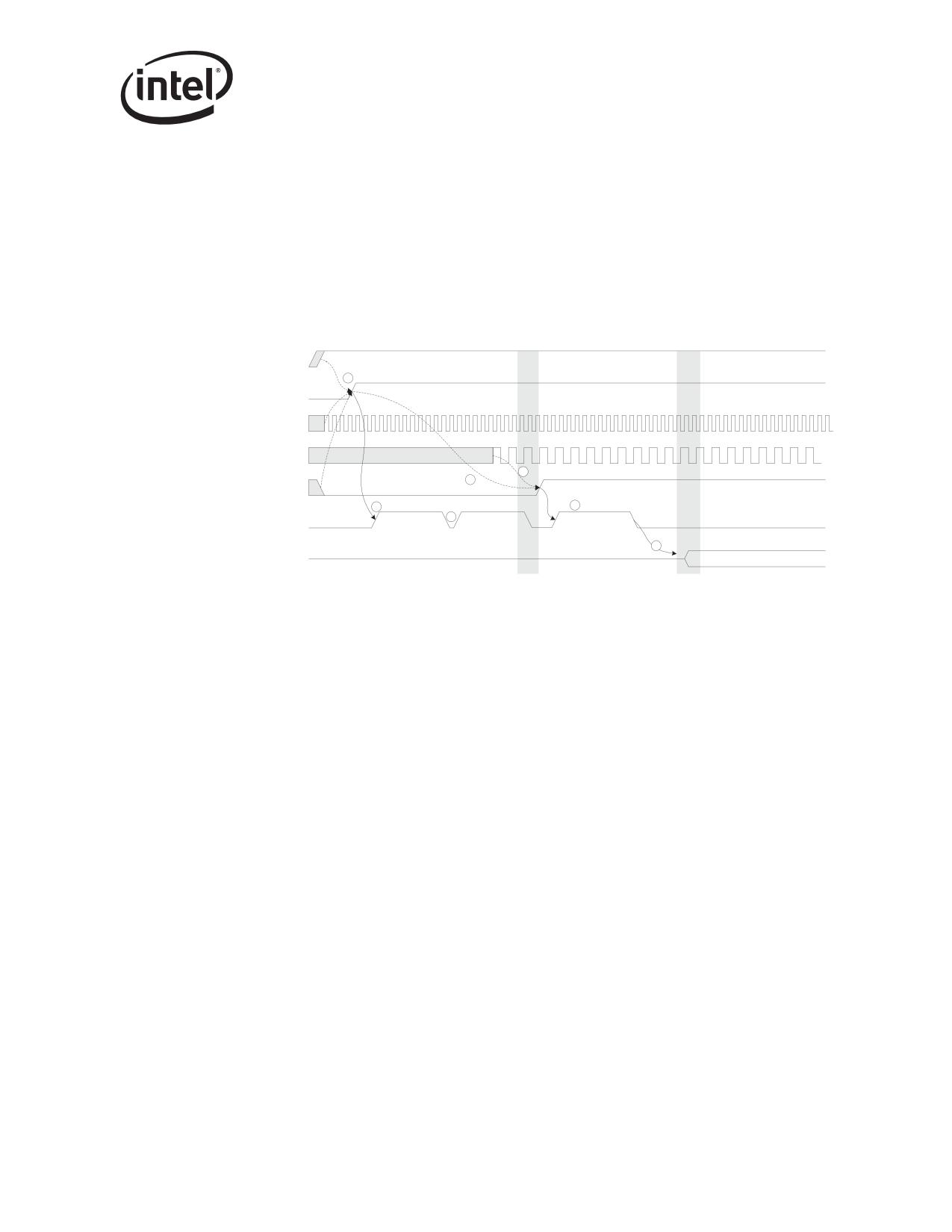
Dual Port Characteristics
The result of multiple LAN devices’ reading EEPROM is that power-on and reset-initiated
EEPROM read sequences might appear slightly differently from the sequences illustrated during
the discussion of power-state transitions (Section 6.3.2). Those illustrations indicate EEPROM
read periods without distinguishing between reads by LAN A versus LAN B devices. At initial
power-on, both LAN devices always execute an EEPROM read sequence. However, since the
enabling/disabling of a particular LAN device occurs on the deassertion of PCI reset, the post-reset
EEPROM read sequence(s) are only performed by LAN device(s) that are enabled. The following
illustration more clearly illustrates the EEPROM read sequence for a scenario where a single LAN
device is enabled:
Power
tppg
1
LAN_PWR_GOOD
ttxpg
125 MHz XTAL IN
CLK
tpgrst
6
tclkpr
5
tpgee
RST#
2
tee
tpree 3
tee
EEPROM read,
3
EEPROM read,
EEPROM read,
Reading EEPROM
LAN A device
LAN B device
LAN A device
9
teepci
PCI Pins
Running
12.4
Shared FLASH
The Ethernet controller provides an interface to an external FLASH/ROM memory device, as
described in Section 7. This FLASH/ROM device can be mapped into memory and/or I/O address
space for each LAN device through the use of PCI Base Address Registers (BARs). Bit 3 of the
EEPROM Initialization Control Word 3 associated with each LAN device selectively disables/
enables whether the FLASH can be mapped for each LAN device by controlling the BAR register
advertisement and writeability.
12.4.1
FLASH Access Contention
Unlike the shared EEPROM implementation, the Ethernet controller does NOT implement any
internal arbitration between FLASH accesses initiated through the LAN A device and those
initiated through the LAN B device. If accesses from both LAN devices are initiated during the
same approximate time window, access contention can occur. If contention occurs, the external
FLASH addresses can be corrupted or unstable throughout the access. During writes to FLASH,
contention can result in corrupt or unstable data values; contention during reads can result in
erroneous read data being returned.
211
Dual Port Characteristics
Note: Access contention to FLASH by both LAN devices is more than likely to result in indeterminate
data results (during read transactions), corrupted FLASH (during write transactions), or other
unpredictable behavior.
To avoid this contention, accesses from both LAN devices MUST be synchronized using external
software synchronization of the memory or I/O transactions responsible for the access. It might be
possible to ensure contention-avoidance simply by nature of software sequentially.
12.5
LAN Disable
For a LOM design, it might be desirable for the system to provide BIOS-setup capability for
selectively enabling or disabling LOM devices. This might allow an end-user more control over
system resource-management, avoid conflicts with add-in NIC solutions, etc. The Ethernet
controller provides support for selectively enabling or disabling one or both LAN device(s) in the
system.
12.5.1
Overview
Device presence (or non-presence) must be established early during BIOS execution in order to
ensure that BIOS resource-allocation (of interrupts, of memory or IO regions) is done according to
devices that are present only. This is frequently accomplished using a BIOS CVDR (Configuration
Values Driven on Reset) mechanism. The Ethernet controller LAN-disable mechanism is
implemented in order to be compatible with such a solution. The Ethernet controller samples two
pins (FLASH data pins, bits 1 and 0) on reset to determine the LAN-enable configuration.
When a particular LAN is disabled, all internal clocks to that LAN are disabled, the device is held
in reset, and the internal PHY for that LAN is powered-down. The device does not respond to PCI
configuration cycles. Effectively, the LAN device becomes invisible to the system from both a
configuration and power-consumption standpoint.
Note:
Since the LAN-disable mechanisms is implemented using the FLASH data pins, this mechanism
can only be used when no FLASH device is present (FLASH disabled). An Ethernet controller-
based NIC built with support for a FLASH device always enables both LAN devices.
12.5.2
Values Sampled on Reset
The Ethernet controller samples values from the pins FLSH_DATA[1] and FLSH_DATA[0] on the
rising edge of LAN_PWR_GOOD and RST#. Based on the values sampled, the LAN devices are
enabled/disabled according to the following table:
Pin sampled
LAN device controlled
Enable/Disable
Vcc/logic 1b = enabled
FLSH_DATA[0]
LAN A device
Vss/logic 0b = disabled
FLSH_DATA[1]
LAN B device
???
212
Dual Port Characteristics
12.5.3
Multi-Function Advertisement
If one of the LAN devices is disabled, the Ethernet controller no longer is a multi-function device.
It normally reports a 01h in the PCI Configuration Header field Header Type, indicating multi-
function capability. However, if a LAN id disabled, it reports a 0h in this filed to signify single-
function capability.
12.5.4
Interrupt Use
When both LAN devices are enabled, the Ethernet controller uses both the INTA# and INTB# pins
for interrupt-reporting. The EEPROM Initialization Control Word 3 (bit 4) associated with each
LAN device controls which of these two pins is used for each LAN device. The specific interrupt
pin used is reported in the PCI Configuration Header Interrupt Pin field associated with each LAN
device.
However, if either LAN device is disabled, then the INTA# be used for the remaining LAN device,
regardless of the EEPROM configuration. Under these circumstances, the Interrupt Pin field of the
PCI Header always reports a value of 1h, indicating INTA# usage.
12.5.5
Power Reporting
When both LAN devices are enabled, the PCI Power Management Register Block has the
capability of reporting a Common Power value. The Common Power value is reflected in the data
field of the PCI Power Management registers. The value reported as Common Power is specified
via EEPROM, and is reflected in the data field each time the Data_Select field has a value of 8h
(8h = Common Power Value Select).
When either LAN is disabled and the Ethernet controller appears as a single-function device, the
Common Power value, if selected, reports 0h (undefined value), as Common Power is undefined
for a single-function device.
213
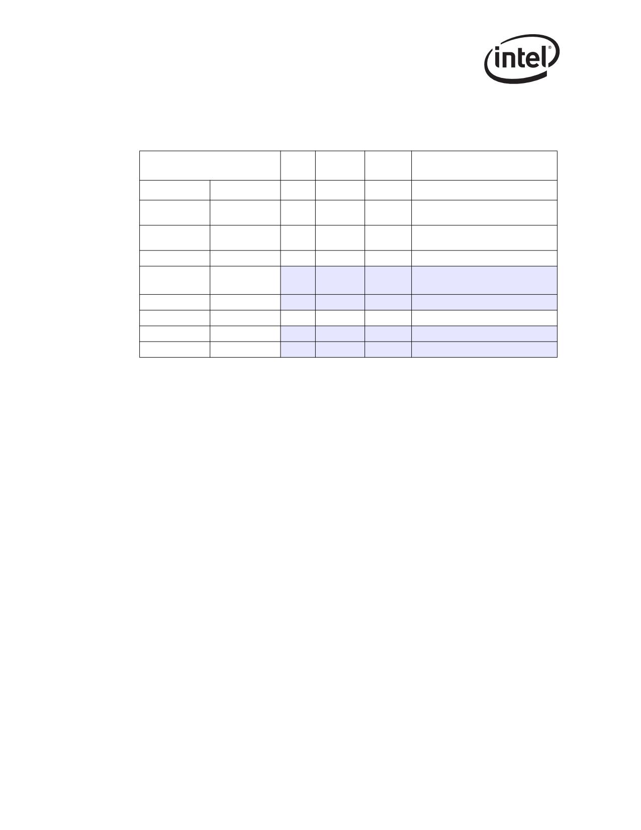
Dual Port Characteristics
12.5.6
Summary
The following table lists the various LAN enabled/disabled configurations possible:
LAN
Enabled/
PCI
CVDR values sampled-on-reset
Interrupt Line Used
device
Disabled
function
FLSH_DATA[1]
FLSH_DATA[0]
INTA# or INTB# (specified by LAN A
1
1
A
0
(enabled)
EEPROM InitCtrl3 value)
INTA# or INTB# (specified by LAN B
B
1
(enabled)
EEPROM InitCtrl3 value)
0
1
A
÷
0
INTA#
X
B
n/a
n/a
(disabled)
1
0
A
C
n/a
n/a
B
X
0
INTA#
0
0
A
X
n/a
n/a
B
X
n/a
n/a
214

Register Descriptions
13
13.1
Introduction
This section details the state inside the PCI/PCI-X Family of Gigabit Ethernet Controllers that are
visible to the programmer. In some cases, it describes hardware structures invisible to software in
order to clarify a concept.
The address space within the Ethernet controller is divided up into eight main categories:
• PCI
• General Configuration and Wakeup
• Interrupt
• MAC Receive
• MAC Transmit
• PHY Receive, Transmit and Special Function
• Statistics
• Diagnostic State (not used in normal operation)
The Ethernet controller’s address space is mapped into four regions with PCI Base Address
Registers described in Table 13-2. These regions are shown as follows.
Internal registers and memories (including PHY)
Memory
128 KB
Flash (optional)
Memory
64 - 512 KB
Expansion ROM (optional)
Memory
64 - 512 KB
Internal registers and memories, Flash (optional)
I/O
8 Bytes
Both the Flash an Expansion ROM Base Address Registers map the same Flash memory. The
internal registers and memories and Flash can be access through I/O space by doing a level of
indirection, as explained later.
Note: The PHY registers are accessed indirectly through the MDI/O interface described in Section 8.2.
13.2
Register Conventions
All registers in the Ethernet controller are defined to be 32 bits, should be accessed as 32-bit double
words, and are aligned on a 64-bit boundary. There are exceptions to this rule:
• PCI configuration registers
• I/O space registers (IOADDR and IODATA) are aligned on 32-bit boundaries
• Register pairs where two 32-bit registers make up a larger logical size
• Accesses to Flash memory (through Expansion ROM space or secondary Base Address
Register space) can be byte, word, double word or quadword accesses.
• Reserved bit positions. Some registers contain certain bits that are marked as “reserved.”
These bits should never be set to a value of 1b by software. Reads from registers containing
reserved bits can return indeterminate values in the reserved bit positions unless read values
are explicitly stated. When read, these reserved bits should be ignored by software.
215
Register Descriptions
• Reserved and/or undefined addresses. Any register not explicitly declared in this
specification should be considered to be reserved and should not be written. Writing to
reserved or undefined register addresses can cause indeterminate behavior. Reads from
reserved or undefined configuration register addresses can return indeterminate values unless
read values are explicitly stated for specific addresses.
• Initial values. Most registers define the initial hardware values prior to being programmed. In
some cases, hardware initial values are undefined and are listed as such via the text
“undefined,” “unknown,” or “X.” Some such values might need setting through EEPROM
configuration or software in order for proper operation to occur; this need is dependent on the
function of the bit. Other registers might cite a hardware default that is overridden by a higher
precedence operation. Operations that might supersede hardware defaults can include a valid
EEPORM load, completion of a hardware operation (such as hardware Auto-Negotiation), or
writing of a different register whose value is then reflected in another bit.
For registers that should be accessed as 32-bit double words, partial writes (less than a 32-bit
double word) is ignored. Partial reads return all 32 bits of data regardless of the byte enables.
Partial reads to read-on-clear registers (for example, ICR) can have unexpected results since all 32
bits are actually read regardless of the byte enables. Partial reads should not be performed.
All statistics registers are implemented as 32-bit registers. 64-bit accesses to these registers must
have the upper byte enables deasserted. 32-bit registers with addresses not on a quadword
boundary cannot be accessed through a 64-bit access.
Note:
The PHY registers are accessed indirectly through the MDI/O interface.
13.2.1
Memory and I/O Address Decoding
13.2.1.1
Memory-Mapped Access to Internal Registers and Memories
The internal registers and memories can be accessed as direct memory-mapped offsets from the
base address register (BAR0 or BAR0/BAR1, see Section 4.1). Refer to Table 13-2 for the
appropriate offset for each specific internal register.
13.2.1.2
Memory-Mapped Access to FLASH
The external Flash can be accessed using direct memory-mapped offsets from the Flash base
address register (BAR1 or BAR2/BAR3, see Section 4.1). The Flash is only accessible if enabled
through the EEPROM Initialization Control Word, and if the Flash Base Address register contains
a valid (non-zero) base memory address. For accesses, the offset from the Flash BAR corresponds
to the offset into the flash actual physical memory space.
13.2.1.3
Memory-Mapped Access to Expansion ROM
The external Flash can also be accessed as a memory-mapped expansion ROM. Accesses to offsets
starting from the Expansion ROM Base address (see Section 4.1) reference the Flash provided that
access is enabled through the EEPROM Initialization Control Word, and if the Expansion ROM
Base Address register contains a valid (non-zero) base memory address.
216

Register Descriptions
13.2.2
I/O-Mapped Internal Register, Internal Memory, and Flash1
To support pre-boot operation (prior to the allocation of physical memory base addresses), all
internal registers, memories, and Flash can be accessed using I/O operations. I/O accesses are
supported only if an I/O Base Address is allocated and mapped (BAR2 or BAR4, see Section 4.1),
the BAR contains a valid (non-zero value), and I/O address decoding is enabled in the PCI/PCIX
configuration.
When an I/O BAR is mapped, the I/O address range allocated opens a 32-byte window in the
system I/O address map. Within this window, two I/O addressable registers are implemented:
IOADDR and IODATA. The IOADDR register is used to specify a reference to an internal register,
memory, or Flash, and then the IODATA register is used as a window to the register, memory or
Flash address specified by IOADDR:
Offset
Abbreviation
Name
RW
Size
Internal Register, Internal Memory, or Flash Location
Address
00000000h
IOADDR
00000h - 1FFFFh - Internal Registers and Memories
RW
4 bytes
20000h - 7FFFFh - Undefined
80000h - FFFFFh - Flash
Data field for reads or writes to the Internal Register Internal
00000004h
IODATA
Memory, or Flash location as identified by the current value
RW
4 bytes
in IOADDR. All 32 bits of this register are read/write-able.
13.2.2.1
IOADDR
The IOADDR register must always be written as a DWORD access (for example, the C/BE#[3:0]
byte enables must all be enabled). Writes that are less than 32 bits are ignored. Reads of any size
return a DWORD of data. However, the chipset or CPU can only return a subset of that DWORD.
For Intel architecture programmers, the IN and OUT instructions must be used to cause I/O cycles
to be used on the PCI bus. Since writes must be to a 32-bit quantity, the source register of the OUT
instruction must be EAX (the only 32-bit register supported by the OUT command). For reads, the
IN instruction can have any size target register, but it is recommended that the 32-bit EAX register
be used.
Since only a particular range is addressable, the upper bits of this register are hard coded to 0b. Bits
31 through 20 are not write-able and always read back as 0b.
At hardware reset (LAN_PWR_GOOD) or PCI Reset, this register value resets to 00h. Once
written, the value is retained until the next write or reset.
13.2.2.2
IODATA
The IODATA register must always be written as a DWORD access when the IOADDR register
contains a value for the Internal Register and Memories (00000h - 1FFFCh). In this case, writes
less than 32 bits are ignored.
1.
Not applicable to the 82547GI/EI.
217

Register Descriptions
The IODATA register can be written as a byte, word, or Dword access when the IOADDR register
contains a value for the Flash (80000h - FFFFFh). In this case, the value in IOADDR must be
properly aligned to the data value. Additionally, the lower 2 bits of the IODATA PCI-X access must
correspond to the byte, word, or Dword access.Table 13-1 lists the supported configurations:
Table 13-1. IODATA Register Configurations
Ethernet Controller
PCI-X1 IODATA Access
PCI-X IODATA Access
Access Type
IOADDR Register Bits
AD[1:0] Bits in Address
AD C/BE#[3:0] Bits in
[1:0]
Phase
Data Phase
BYTE (8 bits)
00b
00b
1110b
01b
01b
1101b
10b
10b
1011b
11b
11b
0111b
WORD (16 bits)
00b
00b
1100b
10b
10b
0011b
DWORD (32 bits)
00b
00b
0000b
1.
The 82540EP/EM does not support PCI-X.
Software might need to implement special code to access the Flash memory at a byte or word at a
time. Example code that reads a Flash byte is shown here to illustrate the impact of Table 13-1:
char *IOADDR;
char *IODATA;
IOADDR = IOBASE + 0;
IODATA = IOBASE + 4;
*(IOADDR) = Flash_Byte_Address;
Read_Data = *(IODATA + (Flash_Byte_Address % 4));
Reads to IODATA of any size returns a Dword of data. However, the chipset or CPU can only
return a subset of that Dword.
For Intel architecture programmers, the IN and OUT instructions must be used to cause I/O cycles
to be used on the PCI bus. Where 32-bit quantities are required on writes, the source register of the
OUT instruction must be EAX (the only 32-bit register supported by the OUT command).
Writes and reads to IODATA when the IOADDR register value is in an undefined range (20000h -
7FFFCh) should not be performed. Results are indeterminate.
There are no special software timing requirements on accesses to IOADDR or IODATA. All
accesses are immediate except when data is not readily available or acceptable. In this case, the
Ethernet controller delays the results through normal bus methods.
218
Register Descriptions
Table 13-2. Ethernet Controller Register Summary
Category
Offset
Abbreviation
Name
R/W
Page
General
00000h
CTRL
Device Control
R/W
224
General
00008h
STATUS
Device Status
R
229
General
00010h
EECD
EEPROM/Flash Control/Data
R/W
232
EEPROM Read (not applicable to the
General
00014h
EERD
R/W
234
82544GC/EI)
Flash Access (applicable to the 82541xx and
General
0001Ch
FLA
R/W
236
82547GI/EI only)
General
00018h
CTRL_EXT
Extended Device Control
R/W
237
General
00020h
MDIC
MDI Control
R/W
242
General
00028h
FCAL
Flow Control Address Low
R/W
283
General
0002Ch
FCAH
Flow Control Address High
R/W
283
General
00030h
FCT
Flow Control Type
R/W
284
General
00038h
VET
VLAN EtherType
R/W
284
General
00170h
FCTTV
Flow Control Transmit Timer Value
R/W
285
Transmit Configuration Word (not applicable to
General
00178h
TXCW
R/W
286
the 82540EP/EM, 82541xx and 82547GI/EI)
Receive Configuration Word (not applicable to
General
00180h
RXCW
R
287
the 82540EP/EM, 82541xx and 82547GI/EI)
LED Control (not applicable to the 82544GC/
General
00E00h
LEDCTL
R/W
289
EI)
DMA
01000h
PBA
Packet Buffer Allocation
R/W
292
Interrupt
000C0h
ICR
Interrupt Cause Read
R
293
Interrupt Throttling (not applicable to the
Interrupt
000C4h
ITR
R/W
295
82544GC/EI)
Interrupt
000C8h
ICS
Interrupt Cause Set
W
296
Interrupt
000D0h
IMS
Interrupt Mask Set/Read
R/W
297
Interrupt
000D8h
IMC
Interrupt Mask Clear
W
298
Receive
00100h
RCTL
Receive Control
R/W
300
Receive
02160h
FCRTL
Flow Control Receive Threshold Low
R/W
304
Receive
02168h
FCRTH
Flow Control Receive Threshold High
R/W
305
Receive
02800h
RDBAL
Receive Descriptor Base Low
R/W
306
Receive
02804h
RDBAH
Receive Descriptor Base High
R/W
306
Receive
02808h
RDLEN
Receive Descriptor Length
R/W
307
Receive
02810h
RDH
Receive Descriptor Head
R/W
307
Receive
02818h
RDT
Receive Descriptor Tail
R/W
308
Receive
02820h
RDTR
Receive Delay Timer
R/W
308
Receive Interrupt Absolute Delay Timer (not
Receive
0282Ch
RADV
R/W
309
applicable to the 82544GC/EI)
Receive Small Packet Detect Interrupt (not
Receive
02C00h
RSRPD
R/W
310
applicable to the 82544GC/EI)
Transmit
00400h
TCTL
Transmit Control
R/W
310
Transmit
00410h
TIPG
Transmit IPG
R/W
312
Transmit
00458h
AIFS
Adaptive IFS Throttle - AIT
R/W
314
Transmit
03800h
TDBAL
Transmit Descriptor Base Low
R/W
315
Transmit
03804h
TDBAH
Transmit Descriptor Base High
R/W
316
Transmit
03808h
TDLEN
Transmit Descriptor Length
R/W
316
Transmit
03810h
TDH
Transmit Descriptor Head
R/W
317
Transmit
03818h
TDT
Transmit Descriptor Tail
R/W
318
Transmit
03820h
TIDV
Transmit Interrupt Delay Value
R/W
318
219
Register Descriptions
Category
Offset
Abbreviation
Name
R/W
Page
TX DMA Control (applicable to the 82544GC/
TX DMA
03000h
TXDMAC
R/W
319
EI only)
TX DMA
03828h
TXDCTL
Transmit Descriptor Control
R/W
319
Transmit Absolute Interrupt Delay Timer (not
TX DMA
0282Ch
TADV
R/W
321
applicable to the 82544GC/EI)
TX DMA
03830h
TSPMT
TCP Segmentation Pad and Threshold
R/W
322
RX DMA
02828h
RXDCTL
Receive Descriptor Control
R/W
324
RX DMA
05000h
RXCSUM
Receive Checksum Control
R/W
325
05200h-
Receive
MTA[127:0]
Multicast Table Array (n)
R/W
327
053FCh
05400h-
Receive
RAL(8n)
Receive Address Low (n)
R/W
329
05478h
05404h-
Receive
RAH(8n)
Receive Address High (n)
R/W
329
0547Ch
05600h-
VLAN Filter Table Array (n)
Receive
VFTA[127:0]
R/W
330
057FCh
Not applicable to the 82541ER
Wakeup
05800h
WUC
Wakeup Control
R/W
331
Wakeup
05808h
WUFC
Wakeup Filter Control
R/W
332
Wakeup
05810h
WUS
Wakeup Status
R
333
Wakeup
05838h
IPAV
IP Address Valid
R/W
335
IP4AT
05840h-
IPv4 Address Table
Wakeup
IPAT (82544GC/
R/W
336
05858h
IP Address Table (82544GC/EI)
EI)
05880h-
IPv6 Address Table (not applicable to the
Wakeup
IP6AT
R/W
337
0588Ch
82544GC/EI)
Wakeup
05900h
WUPL
Wakeup Packet Length
R/W
338
05A00h-
Wakeup
WUPM
Wakeup Packet Memory
R/W
338
05A7Ch
05F00h-
Wakeup
FFLT
Flexible Filter Length Table
R/W
338
05F18h
09000h-
Wakeup
FFMT
Flexible Filter Mask Table
R/W
339
093F8h
09800h-
Wakeup
FFVT
Flexible Filter Value Table
R/W
340
09BF8h
Statistics
04000h
CRCERRS
CRC Error Count
R
341
Statistics
04004h
ALGNERRC
Alignment Error Count
R
341
Statistics
04008h
SYMERRS
Symbol Error Count
R
342
Statistics
0400Ch
RXERRC
RX Error Count
R
342
Statistics
04010h
MPC
Missed Packets Count
R
343
Statistics
04014h
SCC
Single Collision Count
R
343
Statistics
04018h
ECOL
Excessive Collisions Count
R
344
Statistics
0401Ch
MCC
Multiple Collision Count
R
344
Statistics
04020h
LATECOL
Late Collisions Count
R
345
Statistics
04028h
COLC
Collision Count
R
345
Statistics
04030h
DC
Defer Count
R
346
Statistics
04034h
TNCRS
Transmit - No CRS
R
346
Statistics
04038h
SEC
Sequence Error Count
R
347
Statistics
0403Ch
CEXTERR
Carrier Extension Error Count
R
347
Statistics
04040h
RLEC
Receive Length Error Count
R
348
Statistics
04048h
XONRXC
XON Received Count
R
348
Statistics
0404Ch
XONTXC
XON Transmitted Count
R
349
Statistics
04050h
XOFFRXC
XOFF Received Count
R
349
220
Register Descriptions
Category
Offset
Abbreviation
Name
R/W
Page
Statistics
04054h
XOFFTXC
XOFF Transmitted Count
R
349
Statistics
04058h
FCRUC
FC Received Unsupported Count
R/W
350
Statistics
0405Ch
PRC64
Packets Received (64 Bytes) Count
R/W
350
Statistics
04060h
PRC127
Packets Received (65-127 Bytes) Count
R/W
351
Statistics
04064h
PRC255
Packets Received (128-255 Bytes) Count
R/W
351
Statistics
04068h
PRC511
Packets Received (256-511 Bytes) Count
R/W
352
Statistics
0406Ch
PRC1023
Packets Received (512-1023 Bytes) Count
R/W
352
Statistics
04070h
PRC1522
Packets Received (1024-Max Bytes)
R/W
353
Statistics
04074h
GPRC
Good Packets Received Count
R
353
Statistics
04078h
BPRC
Broadcast Packets Received Count
R
354
Statistics
0407Ch
MPRC
Multicast Packets Received Count
R
354
Statistics
04080h
GPTC
Good Packets Transmitted Count
R
355
Statistics
04088h
GORCL
Good Octets Received Count (Low)
R
355
Statistics
0408Ch
GORCH
Good Octets Received Count (Hi)
R
355
Statistics
04090h
GOTCL
Good Octets Transmitted Count (Low)
R
356
Statistics
04094h
GOTCH
Good Octets Transmitted Count (Hi)
R
356
Statistics
040A0h
RNBC
Receive No Buffers Count
R
356
Statistics
040A4h
RUC
Receive Undersize Count
R
357
Statistics
040A8h
RFC
Receive Fragment Count
R
357
Statistics
040ACh
ROC
Receive Oversize Count
R
358
Statistics
040B0h
RJC
Receive Jabber Count
R
358
Management Packets Received Count (not
Statistics
040B4h
MGTPRC
R
359
applicable to the 82544GC/EI or 82541ER)
Management Packets Dropped Count (not
Statistics
040B8h
MGTPDC
R
360
applicable to the 82544GC/EI or 82541ER)
Management Pkts Transmitted Count (not
Statistics
040BCh
MGTPTC
R
360
applicable to the 82544GC/EI or 82541ER)
Statistics
040C0h
TORL
Total Octets Received (Lo)
R
360
Statistics
040C4h
TORH
Total Octets Received (Hi)
R
360
Statistics
040C8h
TOTL
Total Octets Transmitted (Lo)
R
361
Statistics
040CCh
TOTH
Total Octets Transmitted (Hi)
R
361
Statistics
040D0h
TPR
Total Packets Received
R
362
Statistics
040D4h
TPT
Total Packets Transmitted
R
362
Statistics
040D8h
PTC64
Packets Transmitted (64 Bytes) Count
R
363
Statistics
040DCh
PTC127
Packets Transmitted (65-127 Bytes) Count
R
363
Statistics
040E0h
PTC255
Packets Transmitted (128-255 Bytes) Count
R
364
Statistics
040E4h
PTC511
Packets Transmitted (256-511 Bytes) Count
R
364
Statistics
040E8h
PTC1023
Packets Transmitted (512-1023 Bytes) Count
R
365
Packets Transmitted (1024 Bytes or Greater)
Statistics
040ECh
PTC1522
R
365
Count
Statistics
040F0h
MPTC
Multicast Packets Transmitted Count
R
366
Statistics
040F4h
BPTC
Broadcast Packets Transmitted Count
R
366
Statistics
040F8h
TSCTC
TCP Segmentation Context Transmitted Count
R
367
Statistics
040FCh
TSCTFC
TCP Segmentation Context Tx Fail Count
R
367
Diagnostic
02410h
RDFH
Receive Data FIFO Head
R/W
368
Diagnostic
02418h
RDFT
Receive Data FIFO Tail
R/W
368
Diagnostic
02420h
RDFHS
Receive Data FIFO Head Saved Register
R/W
369
Diagnostic
02428h
RDFTS
Receive Data FIFO Tail Saved Register
R/W
369
Diagnostic
02430h
RDFPC
Receive Data FIFO Packet Count
R/W
370
Diagnostic
03410h
TDFH
Transmit Data FIFO Head
R/W
370
221

Register Descriptions
Category
Offset
Abbreviation
Name
R/W
Page
Diagnostic
03418h
TDFT
Transmit Data FIFO Tail
R/W
371
Diagnostic
03420h
TDFHS
Transmit Data FIFO Head Saved Register
R/W
371
Diagnostic
03428h
TDFTS
Transmit Data FIFO Tail Saved Register
R/W
372
Diagnostic
03430h
TDFPC
Transmit Data FIFO Packet Count
R/W
372
10000h-
Diagnostic
PBM
Packet Buffer Memory (n)
R/W
373
1FFFCh
Note: The PHY registers are accessed indirectly through the MDI/O interface described in Section 8.2.
MDI
Category
Abbreviation
Name
R/W
Page
Register
PHY
00d
PCTRL
PHY Control Register
R/W
245
PHY
01d
PSTATUS
PHY Status Register
R
248
PHY
02d
PID
PHY Identifier (LSB)
R
250
PHY
03d
EPID
Extended PHY Identifier (MSB)
R
250
PHY
04d
ANA
Auto-Negotiation Advertisement Register
R/W
251
PHY
05d
LPA
Link Partner Ability Register (Base Page)
R
255
PHY
06d
ANE
Auto-Negotiation Expansion Register
R
258
PHY
07d
NPT
Next Page Transmit Register
R/W
259
PHY
08d
LPN
Link Partner Next Page Register
R
260
PHY
09d
GCON
1000BASE-T Control Register
R/W
261
PHY
10d
GSTATUS
1000BASE-T Status Register
R
262
PHY
15d
EPSTATUS
Extended PHY Status Register
R
263
PHY
16d
PSCON
PHY Specific Control Register
R/W
264
PHY
17d
PSSTAT
PHY Specific Status Register
R
267
PHY
18d
PINTE
PHY Interrupt Enable
R/W
270
PHY
19d
PINTS
PHY Interrupt Status
R
272
EPSCON1
PHY
20d
EPSCON (82544GC/
Extended PHY Specific Control 1
R/W
275
EI)
PHY
21d
PREC
PHY Receive Error Counter
R
277
PHY Global Status
PHY
23d1
PGSTAT
R
279
SPEED_TEN_LED and LINK_ACT_LED2
PHY LED Control
PHY
24d1
PLED
SPEED_100_LED and
R/W
280
SPEED_1000_LED2
Extended PHY Specific Status (not
PHY
26d
EPSCON2
applicable to the 82540EP/EM or 82544GC/
R/W
281
EI)
PHY
27d3
EPSSTAT
Extended PHY Specific Status
R/W
281
Register 30 Page Select (not applicable to
PHY
29d
R30PS
W
281
the 82544GC/EI, 82541xx, or 82547GI/EI)
Register 30 Access Window (not applicable
PHY
30d
R30AW
to the 82544GC/EI, 82541xx, or 82547GI/
R/W
282
EI)
Page Select (82541xx and 82547GI/EI
PHY
31d
PPAGE
R/W
283
only)
1.
Applicable to the 82544GC/EI, 82541xx, and 82547GI/EI only.
2.
Applicable to the 82541xx, and 82547GI/EI only.
3.
Applicable to the 82544GC/EI only.
222

Register Descriptions
13.3
PCI-X Register Access Split1
The PCI-X specification states that accesses to internal device memory spaces must complete
within a specific target initial latency, or else the device should signal that it completes the
transaction later using a split-completion operation. Due to internal access latencies, read accesses
to most device registers in the Ethernet controller exceeds target initial-access latencies, and
therefore are split.
Once a register read operation has been split, the device may, as part of normal operation, initiate a
large inbound or outbound transmit or receive data burst transaction. The split completion for the
pending register read might be forced to wait until the data burst completes. Therefore, the read
access-delay for most registers can be indeterminate (although is generally bounded by the nature
or normal burst transactions).
A small subset of the internal register space has been identified as most critical for high-perfor-
mance driver execution. The variable completion delay for access to some registers could
potentially limit the performance of such critical routines as Interrupt Service Routines (ISRs). To
help minimize potential critical routine performance, read accesses to a small subset of internal
register space will instead complete without being split. These registers are listed as follows:
Category
Offset
Abbreviation
Name
General
00000h
CTRL
Device Control Register
General
00008h
STATUS
Device Status Register
General
00010h
EECD
EEPROM/Flash Control/Data Register
General
00018h
CTRL_EXT
Extended Device Control Register
General
00020h
MDIC
MDI Control Register
General
00028h
FCAL
Flow Control Address Low
General
0002Ch
FCAH
Flow Control Address High
General
00030h
FCT
Flow Control Type
General
00038h
VET
VLAN Ether Type
General
00170h
FCTTV
Flow Control Transmit Timer Value
General
00178h
TXCW
Transmit Configuration Word
General
00180h
RXCW
Receive Configuration Word
General
01000h
PBA
Packet Buffer Allocation
Interrupt
000C0h
ICR
Interrupt Cause Read
Interrupt
000C8h
ICS
Interrupt Cause Set
1.
Not applicable to the 82540EP/EM, 82541xx, or 82547GI/EI.
223
Register Descriptions
Category
Offset
Abbreviation
Name
Interrupt
000D0h
IMS
Interrupt Mask Set/Read
Interrupt
000D8h
IMC
Interrupt Mask Clear
Transmit
00400h
TCTL
Transmit Control
The EEPROM configuration bit “Force CSR Read Split” (Initialization Control Word 2, word 0Fh)
provides the ability to configure the device to split all internal register accesses, rather than
providing non-split behavior for the registers listed.
13.4
Main Register Descriptions
This section contains detailed register descriptions for general purpose, DMA, interrupt, receive,
and transmit registers. These registers correspond to the main functions of the Ethernet controller.
13.4.1
Device Control Register
CTRL (00000h; R/W)
This register and the Extended Device Control register (CTRL_EXT) control the major operational
modes for the Ethernet controller.
While software writes to this register to control device settings, several bits (such as FD and
SPEED) can be overridden depending on other bit settings and the resultant link configuration
determined by the PHY’s Auto-Negotiation resolution.
Note: TBI Mode is used only by the 82544GC/EI Ethernet controller. Internal SerDes mode is used only
by the 82546GB/EB and 82545GM/EM Ethernet controllers.
224

Register Descriptions
Table 13-3. CTRL Register Bit Description
31
0
Device Control Bits
Initial
Field
Bit(s)
Description
Value
Full-Duplex
Enables software to override the hardware Auto-Negotiation
function. The FD sets the duplex mode only if CTRL.FRCDPLX
is set.
When cleared, the Ethernet controller operates in half-duplex;
when set, the Ethernet controller operates in full-duplex.
1b
When the Ethernet controller operates in TBI mode/internal
FD
0
SerDes mode, and the AN Hardware is enabled, this bit is
0b1
ignored. When the Ethernet controller operates in TBI mode/
internal SerDes, and the AN Hardware is disabled, or the link is
forced, this bit should be set by software.
When the Ethernet controller operates in internal PHY mode,
the FD bit is set by software based on AN and data rate
resolution.
Configurable through the EEPROM.
Reserved
2:1
0b
These bits are reserved and should be set to 00b.
Link Reset (not applicable to the 82540EP/EM, 82541xx, or
82547GI/EI)
0b = Normal; 1b = Link Reset
Applicable only in TBI mode/internal SerDes of operation. Used
to reset the link control logic and restart the Auto-Negotiation
LRST
3
1b
process, when TXCW.ANE is set and TBI mode/internal SerDes
is enabled.
When set, transmission and reception are halted regardless of
TBI mode/internal SerDes setting. A transition to 0b initiates the
Auto-Negotiation function. Configurable from the EEPROM,
allowing initiation of Auto-Negotiation function at power up.
Reserved
Reserved
4
0b
Factory use only. Should be written with 0b.
Auto-Speed Detection Enable.
When set, the Ethernet controller automatically detects the
resolved speed of the link by sampling the link in internal PHY
mode and self-configures the appropriate status and control
ASDE
5
0b
bits. Software must also set the SLU bit for this operation. This
function is ignored in TBI mode/internal Serdes. The ASD
feature provides a method of determining the link speed without
the need for software accesses to the MII management
registers.
225

Register Descriptions
Initial
Field
Bit(s)
Description
Value
Set Link Up
In TBI mode/internal SerDes, provides manual link
configuration. When set, the Link Up signal is forced high once
receiver synchronization is achieved (LOS not asserted) using
CTRL.FD to determine the duplex mode. This operation
bypasses the link configuration process. If Auto-Negotiation is
enabled (TXCW.ANE equals 1b), then Set Link Up is ignored.
In internal PHY mode, this bit must be set to 1b to permit the
Ethernet controller to recognize the I_LOS/I_LIND link signal
from the PHY.
SLU
6
0b
The "Set Link Up" is normally initialized to 0b. However, if either
the APM Enable or SMBus Enable bits are set in the EEPROM
then it is initialized to 1b, ensuring MAC/PHY communication
during preboot states (for example, the 82547EI and 82541EI).
Driver software sets this bit when the driver software initializes,
therefore LED indications (link, activity, speed) are not active
until the software driver loads even though the PHY has auto-
negotiated and established link with a partner on the Ethernet.
See Section 8.6 for more information about Auto-Negotiation
and link configuration in the various modes.
Configurable through the EEPROM.
Invert Loss-of-Signal (LOS).
0b = do not invert (active high input signal); 1b = invert signal
(active low input signal).
If using the internal PHY, this bit should be set to 0b to ensure
ILOS
7
0b
proper communication with the MAC. If using an external TBI
device, this bit can be set if the Ethernet controller provides a
link loss indication with negative polarity.
Note: This is a reserved bit for the 82541xx and 82547GI/EI.
Speed selection.
These bits determine the speed configuration and are written by
software after reading the PHY configuration through the MDI/O
interface. These signals are ignored in TBI mode/internal
Serdes or when Auto-Speed Detection (CTRL.ASDE) is
SPEED
9:8
10b
enabled. See Section 8.6 for details.
00b 10 Mb/s
01b 100 Mb/s
10b 1000 Mb/s
11b not used
Reserved
Reserved
10
0b
Should be written with 0b to ensure future compatibility.
Force Speed
When set, the Ethernet controller speed is configured by
CTRL.SPEED bits. The PHY device must resolve to the same
speed configuration or software must manually set it to the
same speed as the Ethernet controller.
FRCSPD
11
1b
When cleared, this allows the PHY device or ASD function
(CTRL.ASDE is set) to set the Ethernet controller speed.
This bit is superseded by the CTRL_EXT.SPD_BYPS bit, which
has a similar function.
Applicable only in internal PHY mode of operation and is
configurable through EEPROM.
226

Register Descriptions
Initial
Field
Bit(s)
Description
Value
Force Duplex
When set, software can override the duplex indication from the
FRCDPLX
12
0b
PHY which is in internal PHY mode. When set the CTRL.FD bit
sets duplex. When cleared, the CTRL.FD is ignored.
Reserved
Reserved
17:13
0b
Should be written with 0b to ensure future compatibility.
Read as 0b
SDP0 Data Value. Used to read (write) value of software-
controllable IO pin SDP0. If SDP0 is configured as an output
SDP0_DATA
18
0b2
(SDP0_IODIR=1b), this bit controls the value driven on the pin
(initial value EEPROM-configurable). If SDP0 is configured as
an input, reads return the current value of the pin.
SDP1 Data Value. Used to read (write) value of software-
controllable IO pin SDP1. If SDP1 is configured as an output
SDP1_DATA
19
0b2
(SDP1_IODIR=1b), this bit controls the value driven on the pin
(initial value EEPROM-configurable). If SDP1 is configured as
an input, reads return the current value of the pin.
D3Cold Wakeup Capability Advertisement Enable. When set,
D3Cold wakeup capability is advertised based on whether the
AUX_PWR pin advertises presence of auxiliary power (yes if
AUX_PWR is indicated, no otherwise). When 0b, however,
ADVD3WUC
20
0b2
D3Cold wakeup capability is not advertised even if AUX_PWR
presence is indicated. Formerly used as SDP2 pin data value,
initial value is EEPROM-configurable.
Note: Not applicable to the 82541ER.
PHY Power-Management Enable. When set, the PHY is
informed of power-state transitions and attempts to auto-
negotiate advertising lower line speeds only (10 or 100 Mb/sec)
when entering D3 or D0u power states with wakeup or
manageability enabled. It again re-negotiates, advertising full
EN_PHY_
0b2
21
speed capabilities (10/100/1000 Mbps) when transitioning back
PWR_MGMT
1b1
to full D0 operational state. If this bit is clear, the PHY automatic
speed/power management capability is disabled, and the PHY
remains operational at its current line speed through power-
state transitions. Formerly used as SDP3 pin data value, initial
value is EEPROM-configurable.
SDP0 Pin Directionality. Controls whether software-controllable
pin SDP0 is configured as an input or output (0b = input, 1b =
SDP0_IODIR
22
0b2
output). Initial value is EEPROM-configurable. This bit is not
affected by software or system reset, only by initial power-on or
direct software writes.
SDP1 Pin Directionality. Controls whether software-controllable
pin SDP1 is configured as an input or output (0b = input, 1b =
SDP1_IODIR
23
0b2
output). Initial value is EEPROM-configurable. This bit is not
affected by software or system reset, only by initial power-on or
direct software writes.
Reserved. Formerly used as SDP2and SDP3 pin input/output
Reserved
25:24
0b
direction control.
227