SYSMAC CPM1/CPM1A/CPM2A/CPM2C/SRM1(–V2). Programmable Controllers (2001) - page 6

Instruction Tables
Section
7-6
7-6
Instruction Tables
This section provides tables of the instructions supported by the CPM1/CPM1A,
CPM2A/CPM2C, and SRM1(-V2) PCs. The first few tables can be used to find
instructions by function code. The last table can be used to find instructions by
mnemonic. In both tables, the @ symbol indicates instructions with differen-
tiated forms.
7-6-1
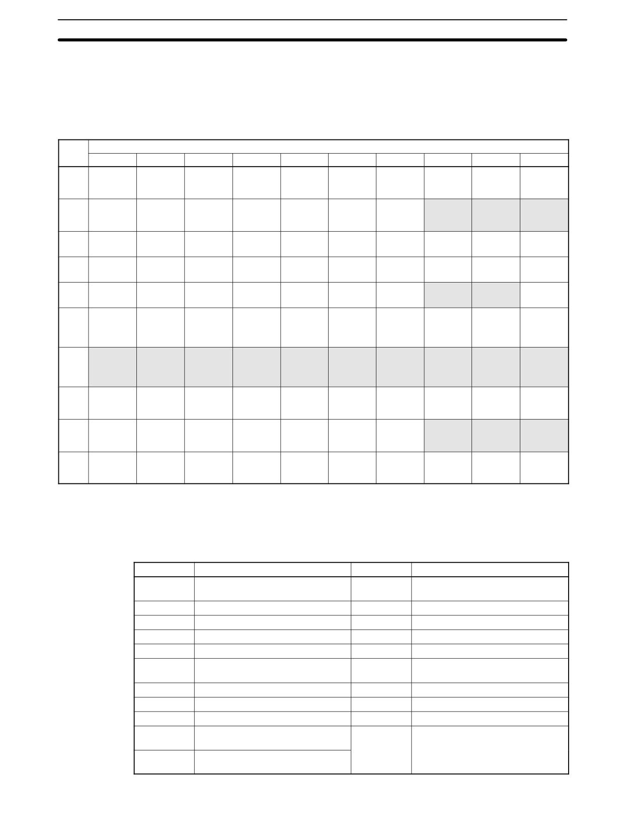
CPM1/CPM1A Function Codes
The following table lists the CPM1/CPM1A instructions that have fixed function
codes. Each instruction is listed by mnemonic and by instruction name. Use the
numbers in the leftmost column as the left digit and the number in the column
heading as the right digit of the function code.
Left
Right digit
dig it
0
1
2
3
4
5
6
7
8
9
0
NOP
END
IL
ILC
JMP
JME
(@) FAL
FALS
STEP
SNXT
NO
END
INTERLOCK
INTERLOCK
JUMP
JUMP END
FAILURE
SEVERE
STEP
STEP START
OPERATION
CLEAR
ALARM AND
FAILURE
DEFINE
RESET
ALARM
1
SFT
KEEP
CNTR
DIFU
DIFD
TIMH
(@) WSFT
(@) ASFT
---
---
SHIFT
KEEP
REVERS-
DIFFER-
DIFFER-
HIGH-
WORD
ASYNCHRO-
REGISTER
IBLE
ENTIATE UP
ENTIATE
SPEED
SHIFT
NOUS SHIFT
COUNTER
DOWN
TIMER
REGISTER
2
CMP
(@) MOV
(@) MVN
(@) BIN
(@) BCD
(@) ASL
(@) ASR
(@) ROL
(@) ROR
(@) COM
COMPARE
MOVE
MOVE NOT
BCD TO
BINARY TO
SHIFT LEFT
SHIFT
ROTATE
ROTATE
COMPLE-
BINARY
BCD
RIGHT
LEFT
RIGHT
MENT
3
(@) ADD
(@) SUB
(@) MUL
(@) DIV
(@) ANDW
(@) ORW
(@) XORW
(@) XNRW
(@) INC
(@) DEC
BCD ADD
BCD
BCD
BCD
LOGICAL
LOGICAL OR
EXCLUSIVE
EXCLUSIVE
INCREMENT
DECRE-
SUBTRACT
MULTIPLY
DIVIDE
AND
OR
NOR
MENT
4
(@) STC
(@) CLC
---
---
---
---
(@) MSG
---
---
---
SET CARRY
CLEAR
MESSAGE
CARRY
DISPLAY
5
(@) ADB
(@) SBB
(@) MLB
(@) DVB
(@) ADDL
(@) SUBL
(@) MULL
(@) DIVL
---
---
BINARY ADD
BINARY
BINARY
BINARY
DOUBLE
DOUBLE
DOUBLE
DOUBLE
SUBTRACT
MULTIPLY
DIVIDE
BCD ADD
BCD
BCD
BCD
SUBTRACT
MULTIPLY
DIVIDE
6
CMPL
(@) INI
(@) PRV
(@) CTBL
(@) SPED
(@) PULS
---
(@) BCNT
(@) BCMP
(@) STIM
DOUBLE
MODE CON-
HIGH-
COMPARI-
SPEED OUT-
SET PULSES
BIT COUNT-
BLOCK
INTERVAL
COMPARE
TROL
SPEED
SON TABLE
PUT (see
(see note)
ER
COMPARE
TIMER
COUNTER
LOAD
note)
PV READ
7
(@) XFER
(@) BSET
---
(@) XCHG
(@) SLD
(@) SRD
(@) MLPX
(@) DMPX
(@) SDEC
---
BLOCK
BLOCK SET
DATA
ONE DIGIT
ONE DIGIT
4-TO-16
16-TO-4
7-SEGMENT
TRANSFER
EXCHANGE
SHIFT LEFT
SHIFT
DECODER
ENCODER
DECODER
RIGHT
8
(@) DIST
(@) COLL
(@) MOVB
(@) MOVD
(@) SFTR
(@) TCMP
(@) ASC
---
---
(@) INT
SINGLE
DATA
MOVE BIT
MOVE DIGIT
REVERS-
TABLE
ASCII
INTERRUPT
WORD
COLLECT
IBLE SHIFT
COMPARE
CONVERT
CONTROL
DISTRIBUTE
REGISTER
9
---
(@) SBS
SBN
RET
---
---
---
(@) IORF
---
(@) MCRO
SUBROU-
SUBROU-
SUBROU-
I/O
MACRO
TINE
TINE
TINE
REFRESH
ENTRY
DEFINE
RETURN
Note Only for the CPM1A transistor output models.
366
Instruction Tables
Section
7-6
7-6-2
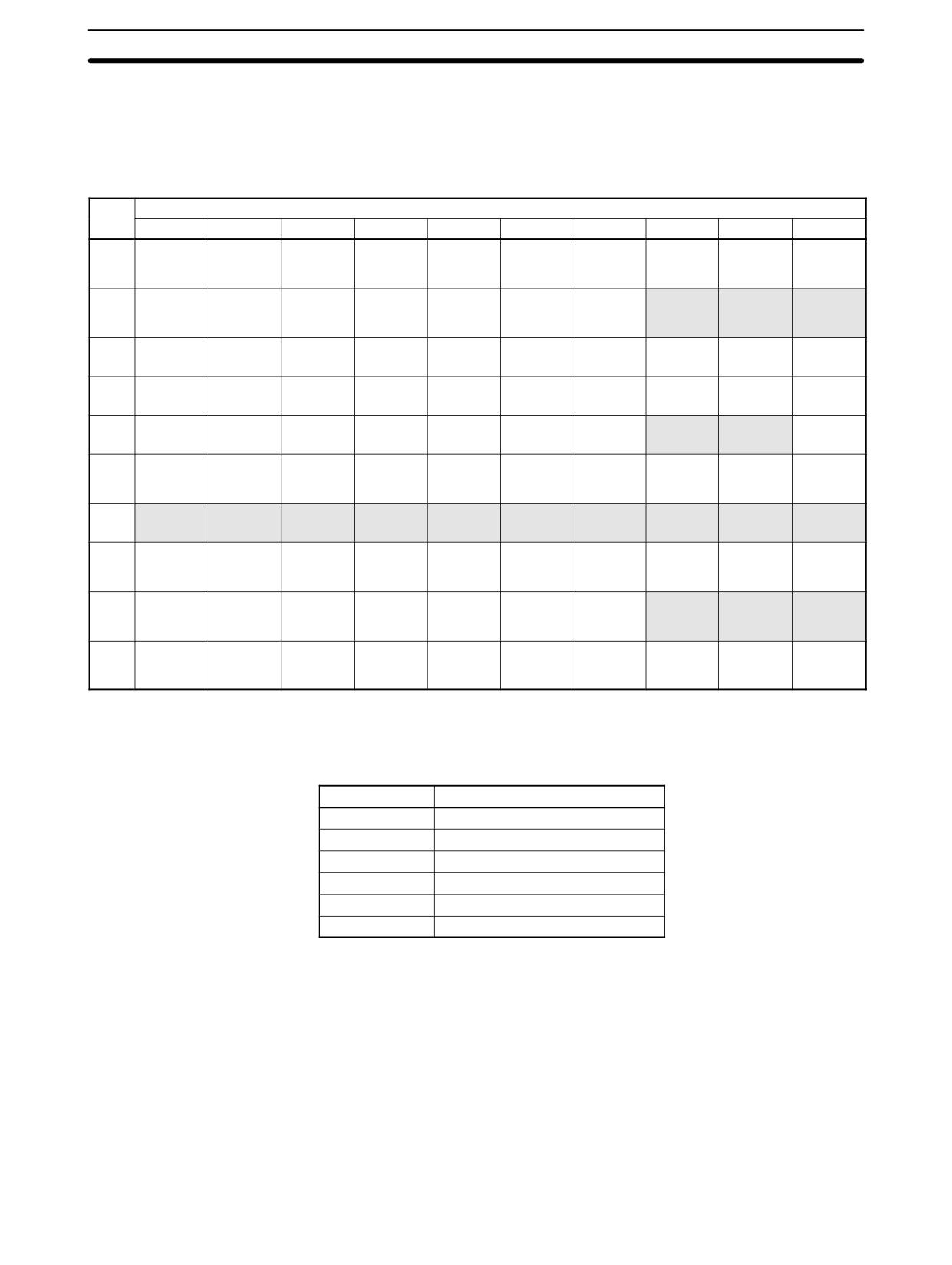
CPM2A/CPM2C Function Codes
The following table lists the CPM2A/CPM2C (including the CPM2C-S) instruc-
tions that have fixed function codes. Each instruction is listed by mnemonic and
by instruction name. Use the numbers in the leftmost column as the left digit and
the number in the column heading as the right digit of the function code.
Left
Right digit
dig it
0
1
2
3
4
5
6
7
8
9
0
NOP
END
IL
ILC
JMP
JME
(@) FAL
FALS
STEP
SNXT
NO
END
INTERLOCK
INTERLOCK
JUMP
JUMP END
FAILURE
SEVERE
STEP
STEP START
OPERATION
CLEAR
ALARM AND
FAILURE
DEFINE
RESET
ALARM
1
SFT
KEEP
CNTR
DIFU
DIFD
TIMH
(@) WSFT
(@) ASFT
---
---
SHIFT
KEEP
REVERS-
DIFFER-
DIFFER-
HIGH-
WORD
ASYNCHRO-
REGISTER
IBLE
ENTIATE UP
ENTIATE
SPEED
SHIFT
NOUS SHIFT
COUNTER
DOWN
TIMER
REGISTER
2
CMP
(@) MOV
(@) MVN
(@) BIN
(@) BCD
(@) ASL
(@) ASR
(@) ROL
(@) ROR
(@) COM
COMPARE
MOVE
MOVE NOT
BCD TO
BINARY TO
SHIFT LEFT
SHIFT
ROTATE
ROTATE
COMPLE-
BINARY
BCD
RIGHT
LEFT
RIGHT
MENT
3
(@) ADD
(@) SUB
(@) MUL
(@) DIV
(@) ANDW
(@) ORW
(@) XORW
(@) XNRW
(@) INC
(@) DEC
BCD ADD
BCD
BCD
BCD
LOGICAL
LOGICAL OR
EXCLUSIVE
EXCLUSIVE
INCREMENT
DECRE-
SUBTRACT
MULTIPLY
DIVIDE
AND
OR
NOR
MENT
4
(@) STC
(@) CLC
---
---
---
---
(@) MSG
(@) RXD
(@) TXD
---
SET CARRY
CLEAR
MESSAGE
RECEIVE
TRANSMIT
CARRY
DISPLAY
5
(@) ADB
(@) SBB
(@) MLB
(@) DVB
(@) ADDL
(@) SUBL
(@) MULL
(@) DIVL
(@) BINL
(@) BCDL
BINARY ADD
BINARY
BINARY
BINARY
DOUBLE
DOUBLE
DOUBLE
DOUBLE
DOUBLE
DOUBLE
SUBTRACT
MULTIPLY
DIVIDE
BCD ADD
BCD
BCD
BCD
BCD-TO-
BINARY-TO-
SUBTRACT
MULTIPLY
DIVIDE
DOUBLE
DOUBLE
BINARY
BCD
6
CMPL
(@) INI
(@) PRV
(@) CTBL
(@) SPED
(@) PULS
(@) SCL
(@) BCNT
(@) BCMP
(@) STIM
DOUBLE
MODE CON-
HIGH-
COMPARI-
SPEED OUT-
SET PULSES
SCALING
BIT COUNT-
BLOCK
INTERVAL
COMPARE
TROL
SPEED
SON TABLE
PUT
ER
COMPARE
TIMER
COUNTER
LOAD
PV READ
7
(@) XFER
(@) BSET
---
(@) XCHG
(@) SLD
(@) SRD
(@) MLPX
(@) DMPX
(@) SDEC
---
BLOCK
BLOCK SET
DATA
ONE DIGIT
ONE DIGIT
4-TO-16
16-TO-4
7-SEGMENT
TRANSFER
EXCHANGE
SHIFT LEFT
SHIFT
DECODER
ENCODER
DECODER
RIGHT
8
(@) DIST
(@) COLL
(@) MOVB
(@) MOVD
(@) SFTR
(@) TCMP
(@) ASC
---
---
(@) INT
SINGLE
DATA
MOVE BIT
MOVE DIGIT
REVERS-
TABLE
ASCII
INTERRUPT
WORD
COLLECT
IBLE SHIFT
COMPARE
CONVERT
CONTROL
DISTRIBUTE
REGISTER
9
---
(@) SBS
SBN
RET
---
---
---
(@) IORF
---
(@) MCRO
SUBROU-
SUBROU-
SUBROU-
I/O
MACRO
TINE
TINE
TINE
REFRESH
ENTRY
DEFINE
RETURN
Note The shaded areas are function codes to which expansion instructions are allo-
cated by default or to which the user can allocate expansion instructions. The
following expansion instructions are available in addition to the ones listed
above with default function codes.
Mnemonic
Name
Mnemonic
Name
(@)ACC
ACCELERATION CONTROL
(@)SCL3
BCD TO SIGNED BINARY
SCALING
AVG
AVERAGE VALUE
(@)SEC
HOURS TO SECONDS
(@)FCS
FCS CALCULATE
(@)SRCH
DATA SEARCH
(@)HEX
ASCII-TO-HEXADECIMAL
(@)STUP
CHANGE RS-232C SETUP
(@)HMS
SECONDS TO HOURS
(@)SUM
SUM CALCULATE
(@)MAX
FIND MAXIMUM
SYNC
SYNCHRONIZED PULSE
CONTROL
(@)MIN
FIND MINIMUM
TIML
LONG TIMER
(@)NEG
2’S COMPLEMENT
TMHH
VERY HIGH-SPEED TIMER
PID
PID CONTROL
ZCP
AREA RANGE COMPARE
(@)PWM
PULSE WITH VARIABLE DUTY
ZCPL
DOUBLE AREA RANGE
RATIO
COMPARE
(@)SCL2
SIGNED BINARY TO BCD
SCALING
367
Instruction Tables
Section
7-6
7-6-3
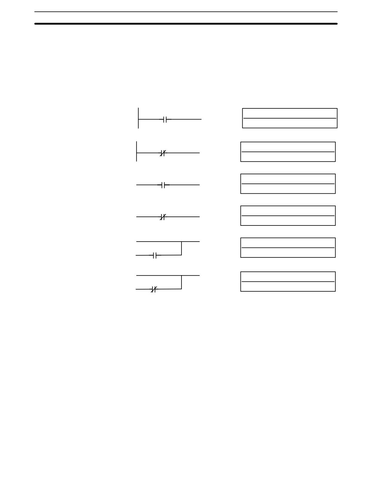
SRM1(-V2) Function Codes
The following table lists the SRM1(-V2) instructions that have fixed function
codes. Each instruction is listed by mnemonic and by instruction name. Use the
numbers in the leftmost column as the left digit and the number in the column
heading as the right digit of the function code.
Left
Right digit
dig it
0
1
2
3
4
5
6
7
8
9
0
NOP
END
IL
ILC
JMP
JME
(@) FAL
FALS
STEP
SNXT
NO
END
INTERLOCK
INTERLOCK
JUMP
JUMP END
FAILURE
SEVERE
STEP
STEP START
OPERATION
CLEAR
ALARM AND
FAILURE
DEFINE
RESET
ALARM
1
SFT
KEEP
CNTR
DIFU
DIFD
TIMH
(@) WSFT
(@) ASFT
---
---
SHIFT
KEEP
REVERS-
DIFFER-
DIFFER-
HIGH-
WORD
ASYNCHRO-
REGISTER
IBLE
ENTIATE UP
ENTIATE
SPEED
SHIFT
NOUS SHIFT
COUNTER
DOWN
TIMER
REGISTER
2
CMP
(@) MOV
(@) MVN
(@) BIN
(@) BCD
(@) ASL
(@) ASR
(@) ROL
(@) ROR
(@) COM
COMPARE
MOVE
MOVE NOT
BCD TO
BINARY TO
SHIFT LEFT
SHIFT
ROTATE
ROTATE
COMPLE-
BINARY
BCD
RIGHT
LEFT
RIGHT
MENT
3
(@) ADD
(@) SUB
(@) MUL
(@) DIV
(@) ANDW
(@) ORW
(@) XORW
(@) XNRW
(@) INC
(@) DEC
BCD ADD
BCD
BCD
BCD
LOGICAL
LOGICAL OR
EXCLUSIVE
EXCLUSIVE
INCREMENT
DECRE-
SUBTRACT
MULTIPLY
DIVIDE
AND
OR
NOR
MENT
4
(@) STC
(@) CLC
---
---
---
---
(@) MSG
(@) RXD
(@) TXD
---
SET CARRY
CLEAR
MESSAGE
RECEIVE
TRANSMIT
CARRY
DISPLAY
5
(@) ADB
(@) SBB
(@) MLB
(@) DVB
(@) ADDL
(@) SUBL
(@) MULL
(@) DIVL
---
---
BINARY ADD
BINARY
BINARY
BINARY
DOUBLE
DOUBLE
DOUBLE
DOUBLE
SUBTRACT
MULTIPLY
DIVIDE
BCD ADD
BCD
BCD
BCD
SUBTRACT
MULTIPLY
DIVIDE
6
CMPL
---
---
---
---
---
(@) SCL
(@) BCNT
(@) BCMP
(@) STIM
DOUBLE
SCALING
BIT COUNT-
BLOCK
INTERVAL
COMPARE
ER
COMPARE
TIMER
7
(@) XFER
(@) BSET
---
(@) XCHG
(@) SLD
(@) SRD
(@) MLPX
(@) DMPX
(@) SDEC
---
BLOCK
BLOCK SET
DATA
ONE DIGIT
ONE DIGIT
4-TO-16
16-TO-4
7-SEGMENT
TRANSFER
EXCHANGE
SHIFT LEFT
SHIFT
DECODER
ENCODER
DECODER
RIGHT
8
(@) DIST
(@) COLL
(@) MOVB
(@) MOVD
(@) SFTR
(@) TCMP
(@) ASC
---
---
---
SINGLE
DATA
MOVE BIT
MOVE DIGIT
REVERS-
TABLE
ASCII
WORD
COLLECT
IBLE SHIFT
COMPARE
CONVERT
DISTRIBUTE
REGISTER
9
---
(@) SBS
SBN
RET
---
---
---
---
---
(@) MCRO
SUBROU-
SUBROU-
SUBROU-
MACRO
TINE
TINE
TINE
ENTRY
DEFINE
RETURN
Note The shaded areas are function codes to which expansion instructions are allo-
cated by default or to which the user can allocate expansion instructions. The
following expansion instructions are available in addition to the ones listed
above with default function codes.
Mnemonic
Name
(@)FCS
FCS CALCULATE
(@)HEX
ASCII-TO-HEXADECIMAL
(@)NEG*
2’S COMPLEMENT
PID*
PID CONTROL
(@)STUP
CHANGE RS-232C SETUP
ZCP*
AREA RANGE COMPARE
Note *SCL(66), NEG(--), PID(--), and ZCP
(--) are supported by the
SRM1-C0j-V2 CPUs only.
368
Instruction Tables
Section
7-6
7-6-4
Alphabetic List by Mnemonic
Dashes (“--”) in the Code column indicate expansion instructions, which do not
have fixed function codes. “None” indicates instructions for which function
codes are not used.
In the CPU Units column, “SRM1” indicates all versions of the SRM1 CPU Units
and “SRM1(-V2)” indicates only version 2 of the SRM1 CPU Units.
Mnemonic
Code
Words
Name
CPU Units
Page
ACC (@)
--
4
ACCELERATION CONTROL
CPM2A/CPM2C
487
ADB (@)
50
4
BINARY ADD
All
463
ADD (@)
30
4
BCD ADD
All
453
ADDL (@)
54
4
DOUBLE BCD ADD
All
459
AND
None
1
AND
All
372
AND LD
None
1
AND LOAD
All
373
AND NOT
None
1
AND NOT
All
372
ANDW (@)
34
4
LOGICAL AND
All
476
ASC (@)
86
4
ASCII CONVERT
All
445
ASFT(@)
17
4
ASYNCHRONOUS SHIFT REGISTER
All
406
ASL (@)
25
2
ARITHMETIC SHIFT LEFT
All
401
ASR (@)
26
2
ARITHMETIC SHIFT RIGHT
All
402
AVG
--
4
AVERAGE VALUE
CPM2A/CPM2C
472
BCD (@)
24
3
BINARY TO BCD
All
436
BCDL (@)
59
3
DOUBLE BINARY-TO-DOUBLE BCD
CPM2A/CPM2C
437
BCMP (@)
68
4
BLOCK COMPARE
All
430
BCNT (@)
67
4
BIT COUNTER
All
495
BIN (@)
23
3
BCD-TO-BINARY
All
435
BINL (@)
58
3
DOUBLE BCD-TO-DOUBLE BINARY
CPM2A/CPM2C
436
BSET (@)
71
4
BLOCK SET
All
410
CLC (@)
41
1
CLEAR CARRY
All
453
CMP
20
3
COMPARE
All
428
CMPL
60
4
DOUBLE COMPARE
All
432
CNT
None
2
COUNTER
All
390
CNTR
12
3
REVERSIBLE COUNTER
All
391
COLL (@)
81
4
DATA COLLECT
All
413
COM (@)
29
2
COMPLEMENT
All
475
CTBL(@)
63
4
COMPARISON TABLE LOAD
All
392
DEC (@)
39
2
BCD DECREMENT
All
479
DIFD
14
2
DIFFERENTIATE DOWN
All
376
DIFU
13
2
DIFFERENTIATE UP
All
376
DIST (@)
80
4
SINGLE WORD DISTRIBUTE
All
411
DIV (@)
33
4
BCD DIVIDE
All
457
DIVL (@)
57
4
DOUBLE BCD DIVIDE
All
462
DMPX (@)
77
4
16-TO-4 ENCODER
All
440
DVB (@)
53
4
BINARY DIVIDE
All
466
END
01
1
END
All
377
FAL (@)
06
2
FAILURE ALARM AND RESET
All
381
FALS
07
2
SEVERE FAILURE ALARM
All
381
FCS (@)
--
4
FCS CALCULATE
CPM2A/CPM2C/SRM1(-V2)
496
HEX (@)
--
4
ASCII-TO-HEXADECIMAL
CPM2A/CPM2C/SRM1(-V2)
447
HMS
--
4
SECONDS TO HOURS
CPM2A/CPM2C
450
IL
02
1
INTERLOCK
All
377
369
Instruction Tables
Section
7-6
Mnemonic
Code
Words
Name
CPU Units
Page
ILC
03
1
INTERLOCK CLEAR
All
377
INC (@)
38
2
INCREMENT
All
479
INI (@)
61
4
MODE CONTROL
All
395
INT (@)
89
4
INTERRUPT CONTROL
All
497
IORF (@)
97
3
I/O REFRESH
All except SRM1
494
JME
05
2
JUMP END
All
379
JMP
04
2
JUMP
All
379
KEEP
11
2
KEEP
All
375
LD
None
1
LOAD
All
372
LD NOT
None
1
LOAD NOT
All
372
MAX (@)
--
4
FIND MAXIMUM
CPM2A/CPM2C
468
MCRO (@)
99
4
MACRO
All
482
MIN (@)
--
4
FIND MINIMUM
CPM2A/CPM2C
470
MLB (@)
52
4
BINARY MULTIPLY
All
466
MLPX (@)
76
4
4-TO-16 DECODER
All
438
MOV (@)
21
3
MOVE
All
407
MOVB (@)
82
4
MOVE BIT
All
415
MOVD (@)
83
4
MOVE DIGIT
All
416
MSG (@)
46
2
MESSAGE
All
493
MUL (@)
32
4
BCD MULTIPLY
All
456
MULL (@)
56
4
DOUBLE BCD MULTIPLY
All
462
MVN (@)
22
3
MOVE NOT
All
408
NEG (@)
--
4
2’S COMPLEMENT
CPM2A/CPM2C/SRM1(-V2)
451
NOP
00
1
NO OPERATION
All
377
OR
None
1
OR
All
372
OR LD
None
1
OR LOAD
All
373
OR NOT
None
1
OR NOT
All
372
ORW (@)
35
4
LOGICAL OR
All
477
OUT
None
2
OUTPUT
All
373
OUT NOT
None
2
OUTPUT NOT
All
373
PID
--
4
PID CONTROL
CPM2A/CPM2C/SRM1(-V2)
422
PRV (@)
62
4
HIGH-SPEED COUNTER PV READ
All except SRM1
397
PULS (@)
65
4
SET PULSES
CPM1A/CPM2A/CPM2C
483
(Transistor outputs only)
PWM (@)
--
4
PULSE WITH VARIABLE DUTY RATIO
CPM2A/CPM2C
490
RET
93
1
SUBROUTINE RETURN
All
482
ROL (@)
27
2
ROTATE LEFT
All
402
ROR (@)
28
2
ROTATE RIGHT
All
403
RSET
None
2
RESET
All
374
RXD (@)
47
4
RECEIVE
CPM2A/CPM2C/SRM1
501
SBB (@)
51
4
BINARY SUBTRACT
All
464
SBN
92
2
SUBROUTINE DEFINE
All
482
SBS (@)
91
2
SUBROUTINE ENTRY
All
480
SCL (@)
66
4
SCALING
CPM2A/CPM2C/SRM1(-V2)
417
SCL2 (@)
--
4
SIGNED BINARY TO BCD SCALING
CPM2A/CPM2C
418
SCL3 (@)
--
4
BCD TO SIGNED BINARY SCALING
CPM2A/CPM2C
420
SDEC (@)
78
4
7-SEGMENT DECODER
CPM2A/CPM2C
442
SEC
--
4
HOURS TO SECONDS
CPM2A/CPM2C
449
SET
None
2
SET
All
374
370
Instruction Tables
Section
7-6
Mnemonic
Code
Words
Name
CPU Units
Page
SFT
10
3
SHIFT REGISTER
All
400
SFTR (@)
84
4
REVERSIBLE SHIFT REGISTER
All
405
SLD (@)
74
3
ONE DIGIT SHIFT LEFT
All
404
SNXT
09
2
STEP START
All
381
SPED (@)
64
4
SPEED OUTPUT
CPM1A/CPM2A/CPM2C
485
(Transistor outputs only)
SRCH (@)
--
4
DATA SEARCH
CPM2A/CPM2C
467
SRD (@)
75
3
ONE DIGIT SHIFT RIGHT
All
404
STC (@)
40
1
SET CARRY
All
453
STEP
08
2
STEP DEFINE
All
381
STIM (@)
69
4
INTERVAL TIMER
All
500
STUP
--
3
CHANGE RS-232C SETUP
CPM2A/CPM2C/SRM1
505
SUB (@)
31
4
BCD SUBTRACT
All
454
SUBL (@)
55
4
DOUBLE BCD SUBTRACT
All
460
SUM (@)
--
4
SUM
CPM2A/CPM2C
474
SYNC (@)
--
4
SYNCHRONIZED PULSE CONTROL
CPM2A/CPM2C
492
TCMP (@)
85
4
TABLE COMPARE
All
429
TIM
None
2
TIMER
All
385
TIMH
15
3
HIGH-SPEED TIMER
All
386
TIML
--
4
LONG TIMER
CPM2A/CPM2C
388
TMHH
--
4
VERY HIGH-SPEED TIMER
CPM2A/CPM2C
387
TXD (@)
48
4
TRANSMIT
CPM2A/CPM2C/SRM1
503
WSFT (@)
16
3
WORD SHIFT
All
401
XCHG (@)
73
3
DATA EXCHANGE
All
411
XFER (@)
70
4
BLOCK TRANSFER
All
409
XNRW (@)
37
4
EXCLUSIVE NOR
All
478
XORW (@)
36
4
EXCLUSIVE OR
All
477
ZCP
--
4
AREA RANGE COMPARE
CPM2A/CPM2C/SRM1(-V2)
433
ZCPL
--
4
DOUBLE AREA RANGE COMPARE
CPM2A/CPM2C
434
371
Ladder Diagram Instructions
Section
7-7
7-7
Ladder Diagram Instructions
Ladder diagram instructions include ladder instructions and logic block instruc-
tions and correspond to the conditions on the ladder diagram. Logic block
instructions are used to relate more complex parts.
7-7-1
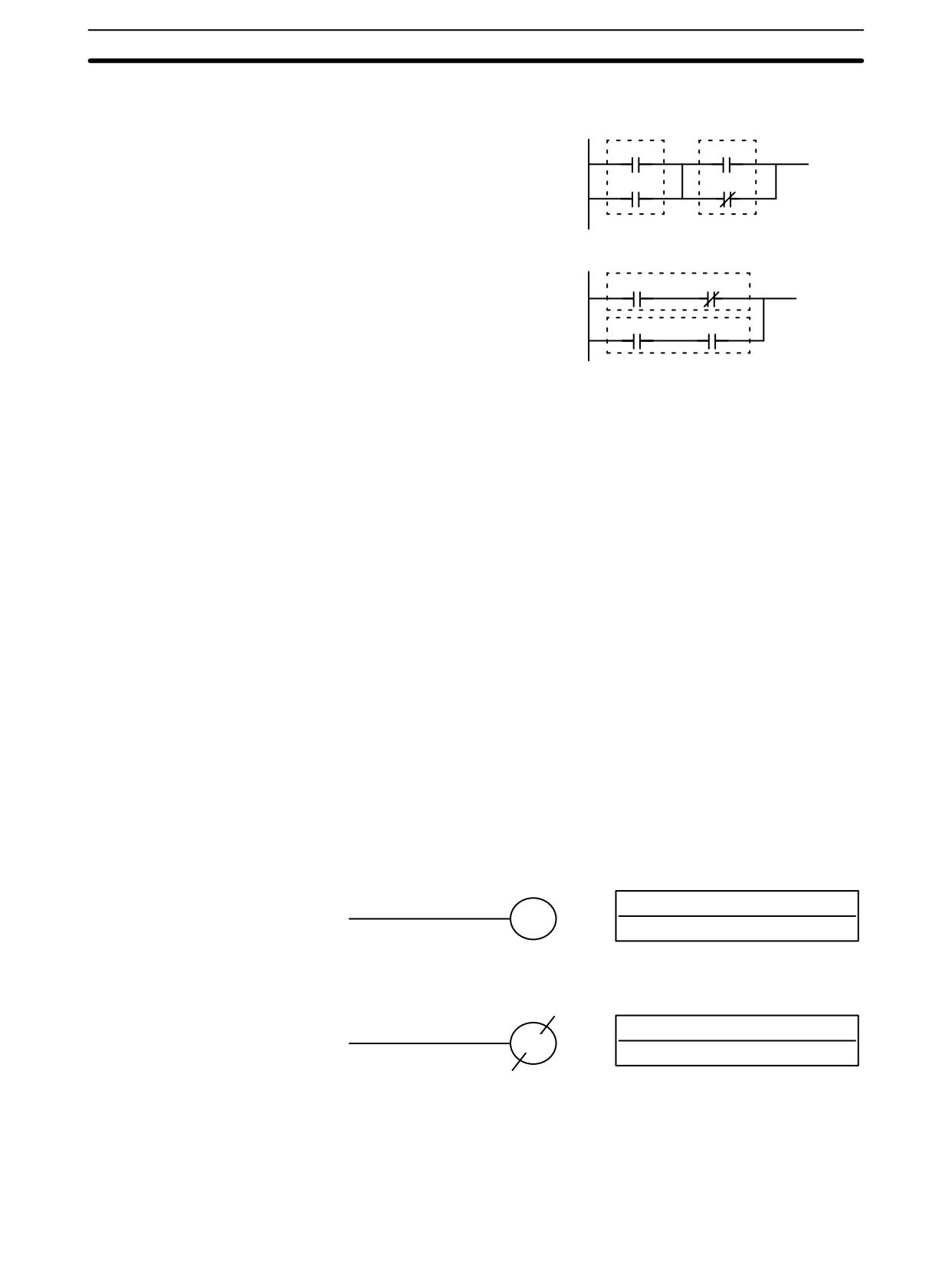
LOAD, LOAD NOT, AND, AND NOT, OR, and OR NOT
Ladder Symbols
Operand Data Areas
B
B: Bit
LOAD - LD
IR, SR, AR, HR, TC, LR, TR
B
B: Bit
LOAD NOT - LD NOT
IR, SR, AR, HR, TC, LR
B
B: Bit
AND - AND
IR, SR, AR, HR, TC, LR
B
B: Bit
AND NOT - AND NOT
IR, SR, AR, HR, TC, LR
B: Bit
OR - OR
B
IR, SR, AR, HR, TC, LR
B: Bit
OR NOT - OR NOT
B
IR, SR, AR, HR, TC, LR
There is no limit to the number of any of these instructions, or restrictions in the
Limitations
order in which they must be used, as long as the memory capacity of the PC is
not exceeded.
These six basic instructions correspond to the conditions on a ladder diagram.
Description
As described in Section 6 Ladder-diagram Programming, the status of the bits
assigned to each instruction determines the execution conditions for all other
instructions. Each of these instructions and each bit address can be used as
many times as required. Each can be used in as many of these instructions as
required.
The status of the bit operand (B) assigned to LD or LD NOT determines the first
execution condition. AND takes the logical AND between the execution condi-
tion and the status of its bit operand; AND NOT, the logical AND between the
execution condition and the inverse of the status of its bit operand. OR takes the
logical OR between the execution condition and the status of its bit operand; OR
NOT, the logical OR between the execution condition and the inverse of the sta-
tus of its bit operand.
Flags
There are no flags affected by these instructions.
372
Bit Control Instructions
Section
7-8
7-7-2
AND LOAD and OR LOAD
AND LOAD - AND LD
00000
00002
Ladder Symbol
00001
00003
OR LOAD - OR LD
00000
00001
Ladder Symbol
00002
00003
When instructions are combined into blocks that cannot be logically combined
Description
using only OR and AND operations, AND LD and OR LD are used. Whereas
AND and OR operations logically combine a bit status and an execution condi-
tion, AND LD and OR LD logically combine two execution conditions, the current
one and the last unused one.
In order to draw ladder diagrams, it is not necessary to use AND LD and OR LD
instructions, nor are they necessary when inputting ladder diagrams directly, as
is possible from the SSS. They are required, however, to convert the program to
and input it in mnemonic form.
In order to reduce the number of programming instructions required, a basic un-
derstanding of logic block instructions is required. For an introduction to logic
blocks, refer to 6-3-6 Logic Block Instructions.
Flags
There are no flags affected by these instructions.
7-8
Bit Control Instructions
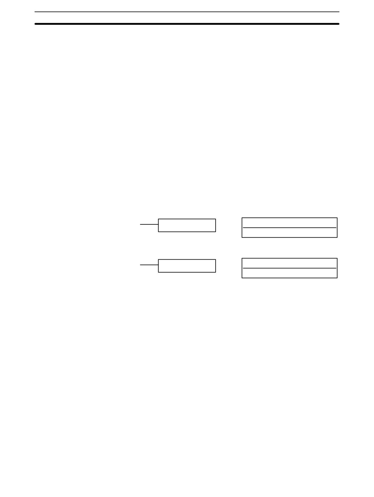
There are seven instructions that can be used generally to control individual bit
status. These are OUT, OUT NOT, DIFU(13), DIFD(14), SET, RSET, and
KEEP(11). These instructions are used to turn bits ON and OFF in different
ways.
7-8-1
OUTPUT and OUTPUT NOT - OUT and OUT NOT
OUTPUT - OUT
Ladder Symbol
Operand Data Areas
B: Bit
B
IR, SR, AR, HR, LR, TR
OUTPUT NOT - OUT NOT
Ladder Symbol
Operand Data Areas
B: Bit
B
IR, SR, AR, HR, LR
Any output bit can generally be used in only one instruction that controls its sta-
Limitations
tus.
Description
OUT and OUT NOT are used to control the status of the designated bit according
to the execution condition.
373
Bit Control Instructions
Section
7-8
OUT turns ON the designated bit for an ON execution condition, and turns OFF
the designated bit for an OFF execution condition. With a TR bit, OUT appears at
a branching point rather than at the end of an instruction line. Refer to 6-3-8
Branching Instruction Lines for details.
OUT NOT turns ON the designated bit for a OFF execution condition, and turns
OFF the designated bit for an ON execution condition.
OUT and OUT NOT can be used to control execution by turning ON and OFF bits
that are assigned to conditions on the ladder diagram, thus determining execu-
tion conditions for other instructions. This is particularly helpful and allows a
complex set of conditions to be used to control the status of a single work bit, and
then that work bit can be used to control other instructions.
The length of time that a bit is ON or OFF can be controlled by combining the
OUT or OUT NOT with TIM. Refer to Examples under 7-15-1 TIMER - TIM for
details.
Flags
There are no flags affected by these instructions.
7-8-2
SET and RESET - SET and RSET
Ladder Symbols
Operand Data Areas
B: Bit
SET B
IR, SR, AR, HR, LR
B: Bit
RSET B
IR, SR, AR, HR, LR
SET turns the operand bit ON when the execution condition is ON, and does not
Description
affect the status of the operand bit when the execution condition is OFF. RSET
turns the operand bit OFF when the execution condition is ON, and does not af-
fect the status of the operand bit when the execution condition is OFF.
The operation of SET differs from that of OUT because the OUT instruction turns
the operand bit OFF when its execution condition is OFF. Likewise, RSET differs
from OUT NOT because OUT NOT turns the operand bit ON when its execution
condition is OFF.
Note On the Programming Console, input SET by pressing the FUN and SET Keys
and input RSET by pressing the FUN and RESET Keys.
Precautions
The status of operand bits for SET and RSET programmed between IL(02) and
ILC(03) or JMP(04) and JME(05) will not change when the interlock or jump
condition is met (i.e., when IL(02) or JMP(04) is executed with an OFF execution
condition).
Flags
There are no flags affected by these instructions.
Examples
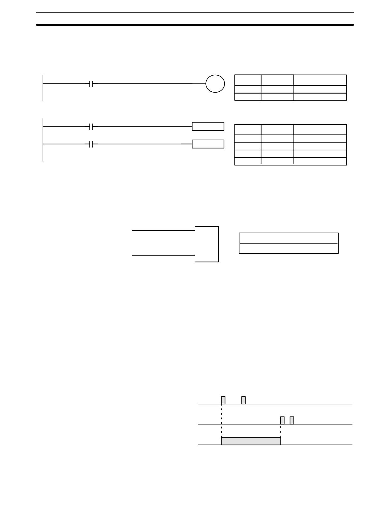
The following examples demonstrate the difference between OUT and SET/
RSET. In the first example (Diagram A), IR 20000 will be turned ON or OFF
whenever IR 00000 goes ON or OFF.
374
Bit Control Instructions
Section
7-8
In the second example (Diagram B), IR 10000 will be turned ON when IR 00001
goes ON and will remain ON (even if IR 00001 goes OFF) until IR 00002 goes
ON.
00000
Address
Instruction
Operands
20000
00000
LD
00000
00001
OUT
20000
Diagram A
00001
SET 20000
Address
Instruction
Operands
00002
00000
LD
00001
RSET 20000
00001
SET
20000
00002
LD
00002
Diagram B
00003
RSET
20000
7-8-3
KEEP - KEEP(11)
Ladder Symbol
Operand Data Areas
S
KEEP(11)
B: Bit
B
IR, SR, AR, HR, LR
R
Any output bit can generally be used in only one instruction that controls its sta-
Limitations
tus.
KEEP(11) is used to maintain the status of the designated bit based on two
Description
execution conditions. These execution conditions are labeled S and R. S is the
set input; R, the reset input. KEEP(11) operates like a latching relay that is set by
S and reset by R.
When S turns ON, the designated bit will go ON and stay ON until reset, regard-
less of whether S stays ON or goes OFF. When R turns ON, the designated bit
will go OFF and stay OFF until reset, regardless of whether R stays ON or goes
OFF. The relationship between execution conditions and KEEP(11) bit status is
shown below.
S execution condition
R execution condition
Status of B
Flags
There are no flags affected by this instruction.
375
Bit Control Instructions
Section
7-8
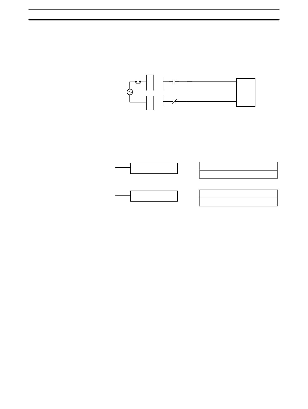
Exercise caution when using a KEEP reset line that is controlled by an external
Precautions
normally closed device. Never use an input bit in an inverse condition on the re-
set (R) for KEEP(11) when the input device uses an AC power supply. The delay
in shutting down the PC’s DC power supply (relative to the AC power supply to
the input device) can cause the designated bit of KEEP(11) to be reset. This situ-
ation is shown below.
Input Unit
A
S
KEEP(11)
NEVER
B
A
R
Bits used in KEEP are not reset in interlocks. Refer to the 7-11 INTERLOCK -
and INTERLOCK CLEAR IL(02) and ILC(03) for details.
7-8-4
DIFFERENTIATE UP and DOWN - DIFU(13) and DIFD(14)
Ladder Symbols
Operand Data Areas
B: Bit
DIFU(13) B
IR, SR, AR, HR, LR
B: Bit
DIFD(14) B
IR, SR, AR, HR, LR
Any output bit can generally be used in only one instruction that controls its sta-
Limitations
tus.
Description
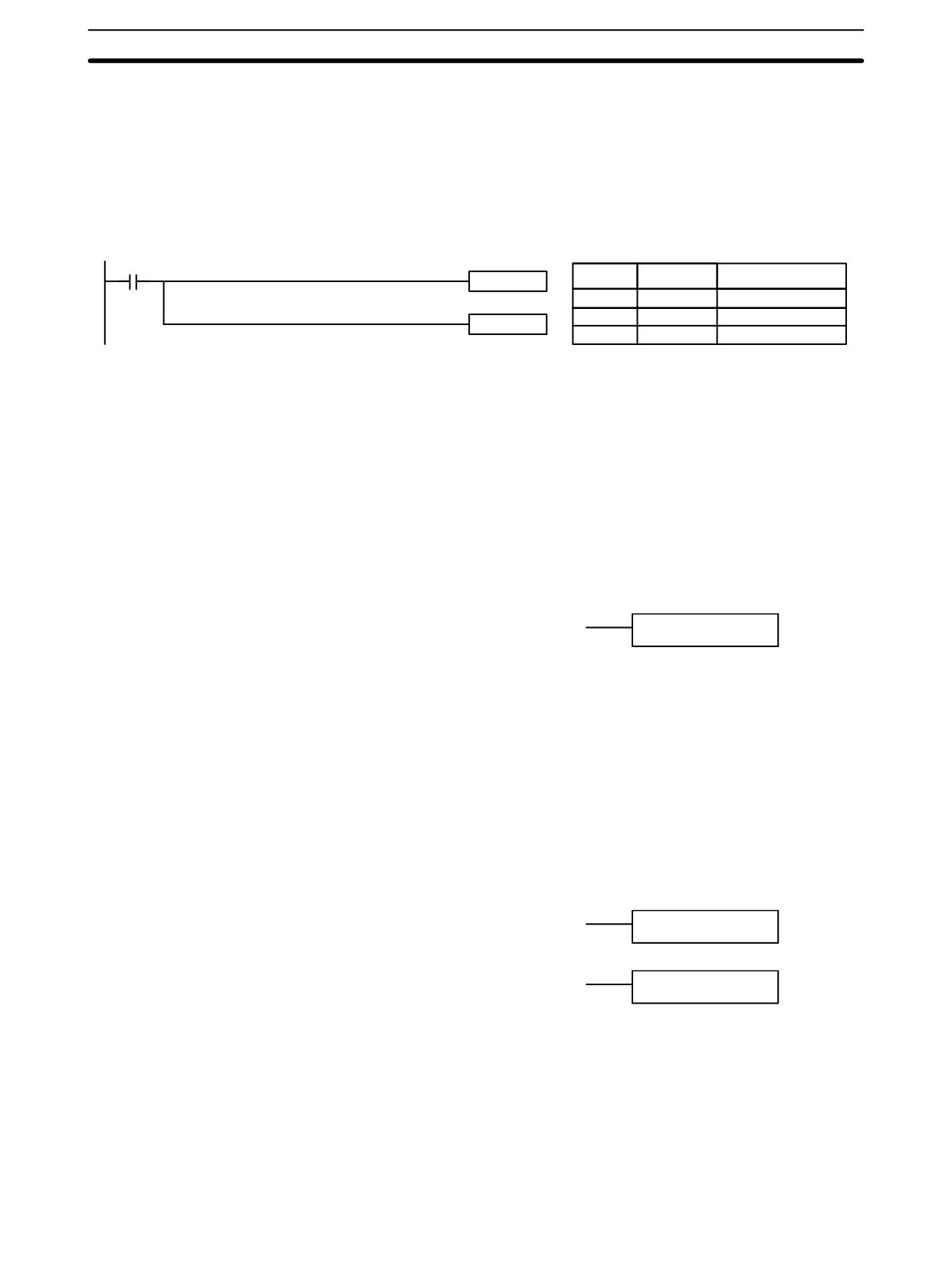
DIFU(13) and DIFD(14) are used to turn the designated bit ON for one cycle
only.
Whenever executed, DIFU(13) compares its current execution with the previous
execution condition. If the previous execution condition was OFF and the cur-
rent one is ON, DIFU(13) will turn ON the designated bit. If the previous execu-
tion condition was ON and the current execution condition is either ON or OFF,
DIFU(13) will either turn the designated bit OFF or leave it OFF (i.e., if the desig-
nated bit is already OFF). The designated bit will thus never be ON for longer
than one cycle, assuming it is executed each cycle (see Precautions, below).
Whenever executed, DIFD(14) compares its current execution with the previous
execution condition. If the previous execution condition was ON and the current
one is OFF, DIFD(14) will turn ON the designated bit. If the previous execution
condition was OFF and the current execution condition is either ON or OFF,
DIFD(14) will either turn the designated bit OFF or leave it OFF. The designated
bit will thus never be ON for longer than one cycle, assuming it is executed each
cycle (see Precautions, below).
These instructions are used when differentiated instructions (i.e., those prefixed
with an @) are not available and single-cycle execution of a particular instruction
is desired. They can also be used with non-differentiated forms of instructions
that have differentiated forms when their use will simplify programming. Exam-
ples of these are shown below.
Flags
There are no flags affected by these instructions.
376
INTERLOCK and INTERLOCK CLEAR - IL(02) and ILC(03)
Section
7-11
DIFU(13) and DIFD(14) operation can be uncertain when the instructions are
Precautions
programmed between IL and ILC, between JMP and JME, or in subroutines. Re-
fer to 7-11 INTERLOCK and INTERLOCK CLEAR - IL(02) and ILC(03), 7-12
JUMP and JUMP END - JMP(04) and JME(05), 7-26 Subroutine Instructions,
and 7-29-1 INTERRUPT CONTROL - INT(89).
Example
In this example, IR 20014 will be turned ON for one cycle when IR 00000 goes
from OFF to ON. IR 20015 will be turned ON for one cycle when IR 00000 goes
from ON to OFF.
00000
Address
Instruction
Operands
DIFU(13) 20014
00000
LD
00000
00001
DIFU(13)
20014
DIFD(14) 20015
00002
DIFD(14)
20015
7-9
NO OPERATION - NOP(00)
Description
NOP(00) is not generally required in programming and there is no ladder symbol
for it. When NOP(00) is found in a program, nothing is executed and the program
execution moves to the next instruction. When memory is cleared prior to pro-
gramming, NOP(00) is written at all addresses. NOP(00) can be input through
the 00 function code.
Flags
There are no flags affected by NOP(00).
7-10
END - END(01)
Ladder Symbol
END(01)
END(01) is required as the last instruction in any program. If there are subrou-
Description
tines, END(01) is placed after the last subroutine. No instruction written after
END(01) will be executed. END(01) can be placed anywhere in the program to
execute all instructions up to that point, as is sometimes done to debug a pro-
gram, but it must be removed to execute the remainder of the program.
If there is no END(01) in the program, no instructions will be executed and the
error message “NO END INST” will appear.
Flags
END(01) turns OFF the ER, CY, GR, EQ, and LE flags.
7-11
INTERLOCK and INTERLOCK CLEAR - IL(02) and ILC(03)
Ladder Symbol
IL(02)
Ladder Symbol
ILC(03)
IL(02) is always used in conjunction with ILC(03) to create interlocks. Interlocks
Description
are used to enable branching in the same way as can be achieved with TR bits,
but treatment of instructions between IL(02) and ILC(03) differs from that with
TR bits when the execution condition for IL(02) is OFF. If the execution condition
of IL(02) is ON, the program will be executed as written, with an ON execution
condition used to start each instruction line from the point where IL(02) is located
through the next ILC(03). Refer to 6-3-8 Branching Instruction Lines for basic
descriptions of both methods.
377
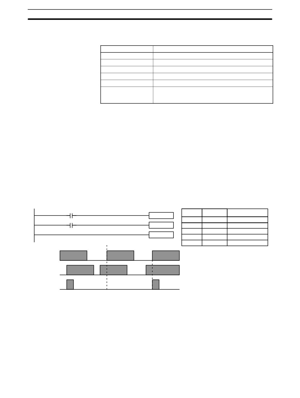
INTERLOCK and INTERLOCK CLEAR - IL(02) and ILC(03)
Section
7-11
If the execution condition for IL(02) is OFF, the interlocked section between
IL(02) and ILC(03) will be treated as shown in the following table:
Instruction
Treatment
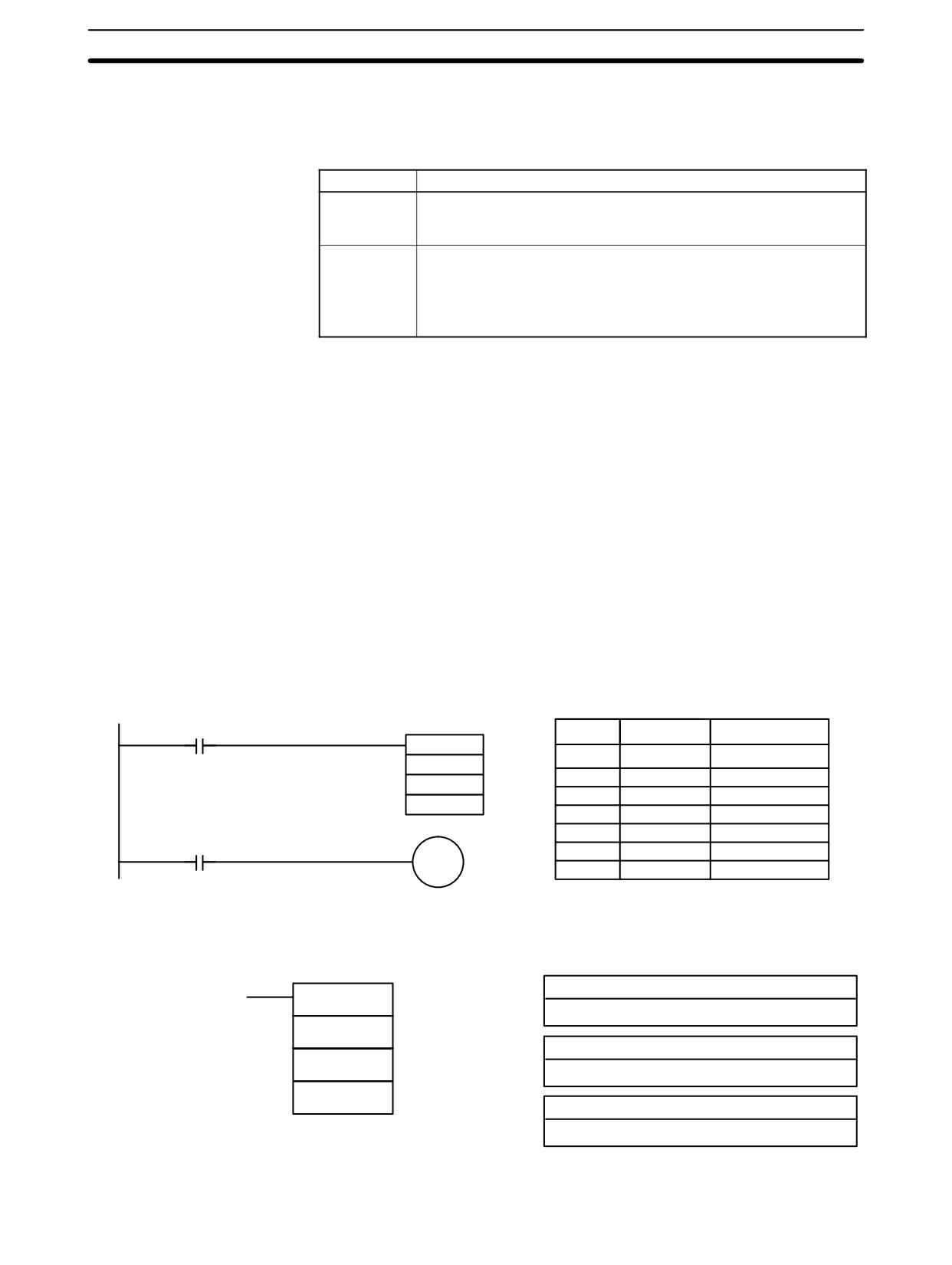
OUT and OUT NOT
Designated bit turned OFF.
TIM and TIMH(15)
Reset.
CNT, CNTR(12)
PV maintained.
KEEP(11)
Bit status maintained.
DIFU(13) and DIFD(14)
Not executed (see below).
All other instructions
The instructions are not executed, and all IR, AR, LR,
HR, and SR bits and words written to as operands in the
instructions are turned OFF.
IL(02) and ILC(03) do not necessarily have to be used in pairs. IL(02) can be
used several times in a row, with each IL(02) creating an interlocked section
through the next ILC(03). ILC(03) cannot be used unless there is at least one
IL(02) between it and any previous ILC(03).
DIFU(13) and DIFD(14) in
Changes in the execution condition for a DIFU(13) or DIFD(14) are not recorded
Interlocks
if the DIFU(13) or DIFD(14) is in an interlocked section and the execution condi-
tion for the IL(02) is OFF. When DIFU(13) or DIFD(14) is execution in an inter-
locked section immediately after the execution condition for the IL(02) has gone
ON, the execution condition for the DIFU(13) or DIFD(14) will be compared to
the execution condition that existed before the interlock became effective (i.e.,
before the interlock condition for IL(02) went OFF). The ladder diagram and bit
status changes for this are shown below. The interlock is in effect while 00000 is
OFF. Notice that 20000 is not turned ON at the point labeled A even though
00001 has turned OFF and then back ON.
00000
Address
Instruction
Operands
IL(02)
00001
00000
LD
00000
DIFU(13) 20000
00001
IL(02)
00002
LD
00001
ILC(03)
00003
DIFU(13)
20000
A
00004
ILC(03)
ON
00000
OFF
ON
00001
OFF
ON
20000
OFF
Precautions
There must be an ILC(03) following any one or more IL(02).
Although as many IL(02) instructions as are necessary can be used with one
ILC(03), ILC(03) instructions cannot be used consecutively without at least one
IL(02) in between, i.e., nesting is not possible. Whenever a ILC(03) is executed,
all interlocks between the active ILC(03) and the preceding ILC(03) are cleared.
When more than one IL(02) is used with a single ILC(03), an error message will
appear when the program check is performed, but execution will proceed nor-
mally.
Flags
There are no flags affected by these instructions.
378
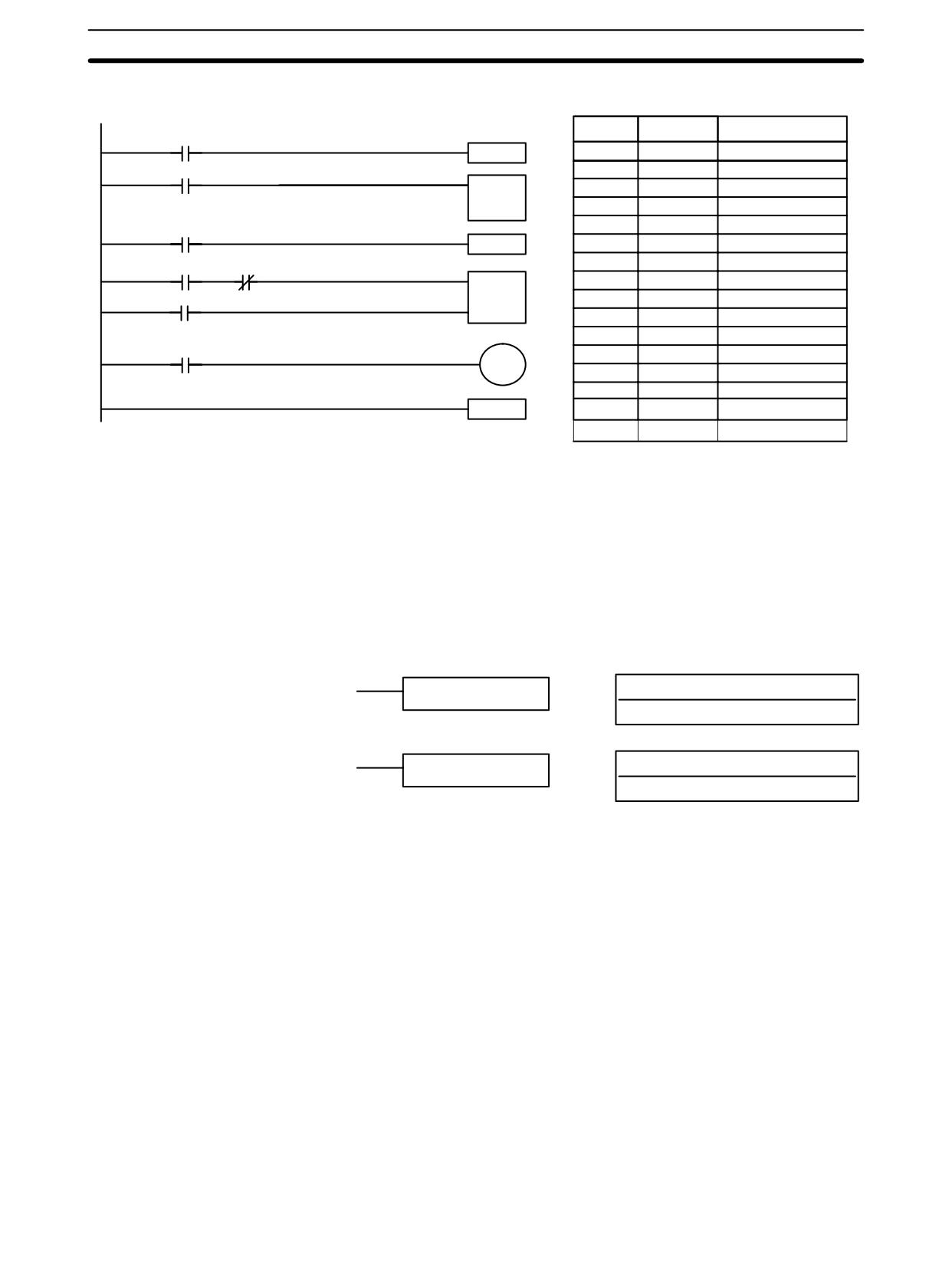
JUMP and JUMP END - JMP(04) and JME(05)
Section
7-12
Example
The following diagram shows IL(02) being used twice with one ILC(03).
Address
Instruction
Operands
00000
IL(02)
00000
LD
00000
00001
00001
IL(02)
TIM 000
00002
LD
00001
#0015
1.5 s
00003
TIM
000
#
0015
00002
IL(02)
00004
LD
00002
00005
IL(02)
00003
00004
CP
00006
LD
00003
CNT
00100
001
00007
AND NOT
00004
R
IR 010
00008
LD
00100
00009
LD
00100
00005
00010
CNT
001
01002
010
00011
LD
00005
ILC(03)
00012
OUT
01002
00013
ILC(03)
When the execution condition for the first IL(02) is OFF, TIM 000 will be reset to
1.5 s, CNT 001 will not be changed, and 01002 will be turned OFF. When the
execution condition for the first IL(02) is ON and the execution condition for the
second IL(02) is OFF, TIM 000 will be executed according to the status of 00001,
CNT 001 will not be changed, and 01002 will be turned OFF. When the execution
conditions for both the IL(02) are ON, the program will execute as written.
7-12
JUMP and JUMP END - JMP(04) and JME(05)
Ladder Symbols
Definer Values
N: Jump number
JMP(04) N
#
N: Jump number
JME(05) N
#
Jump numbers 01 through 49 may be used only once in JMP(04) and once in
Limitations
JME(05), i.e., each can be used to define one jump only. Jump number 00 can be
used as many times as desired.
Description
JMP(04) is always used in conjunction with JME(05) to create jumps, i.e., to skip
from one point in a ladder diagram to another point. JMP(04) defines the point
from which the jump will be made; JME(05) defines the destination of the jump.
When the execution condition for JMP(04) in ON, no jump is made and the pro-
gram is executed consecutively as written. When the execution condition for
JMP(04) is OFF, a jump is made to the JME(05) with the same jump number and
the instruction following JME(05) is executed next.
If the jump number for JMP(04) is between 01 and 49, jumps, when made, will go
immediately to JME(05) with the same jump number without executing any
instructions in between. The status of timers, counters, bits used in OUT, bits
used in OUT NOT, and all other status bits controlled by the instructions between
JMP(04) and JMP(05) will not be changed. Each of these jump numbers can be
used to define only one jump. Because all of instructions between JMP(04) and
JME(05) are skipped, jump numbers 01 through 49 can be used to reduce cycle
time.
379
JUMP and JUMP END - JMP(04) and JME(05)
Section
7-12
Jump Number 00
If the jump number for JMP(04) is 00, the CPU Unit will look for the next JME(05)
with a jump number of 00. To do so, it must search through the program, causing
a longer cycle time (when the execution condition is OFF) than for other jumps.
The status of timers, counters, bits used in OUT, bits used in OUT NOT, and all
other status controlled by the instructions between JMP(04) 00 and JME(05) 00
will not be changed. jump number 00 can be used as many times as desired. A
jump from JMP(04) 00 will always go to the next JME(05) 00 in the program. It is
thus possible to use JMP(04) 00 consecutively and match them all with the same
JME(05) 00. It makes no sense, however, to use JME(05) 00 consecutively, be-
cause all jumps made to them will end at the first JME(05) 00.
DIFU(13) and DIFD(14) in
Although DIFU(13) and DIFD(14) are designed to turn ON the designated bit for
Jumps
one cycle, they will not necessarily do so when written between JMP(04) and
JME(05). Once either DIFU(13) or DIFD(14) has turned ON a bit, it will remain
ON until the next time DIFU(13) or DIFD(14) is executed again. In normal pro-
gramming, this means the next cycle. In a jump, this means the next time the
jump from JMP(04) to JME(05) is not made, i.e., if a bit is turned ON by DIFU(13)
or DIFD(14) and then a jump is made in the next cycle so that DIFU(13) or
DIFD(14) are skipped, the designated bit will remain ON until the next time the
execution condition for the JMP(04) controlling the jump is ON.
When TIMH(15) or TMHH(--) is programmed between JMP(04) and JME(05),
TIMH(15) and TMHH(--) in
Jumps
timing will be performed by interrupt if jump numbers 01 through 49 are used but
timing won’t be performed if jump number 00 is used.
Precautions
When JMP(04) and JME(05) are not used in pairs, an error message will appear
when the program check is performed. This message also appears if JMP(04)
00 and JME(05) 00 are not used in pairs, but the program will execute properly
as written.
Flags
There are no flags affected by these instructions.
Examples
Examples of jump programs are provided in 6-3-9 Jumps.
380
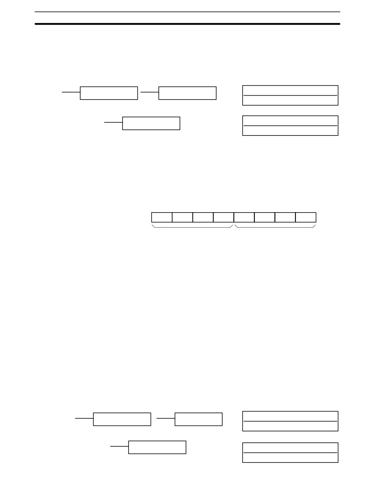
Step Instructions
Section
7-14
7-13
User Error Instructions:
FAILURE ALARM AND RESET - FAL(06) and
SEVERE FAILURE ALARM - FALS(07)
Ladder Symbols
Definer Data Areas
N: FAL number
FAL(06) N
@FAL(06) N
# (00 to 99)
N: FAL number
FALS(07) N
# (01 to 99)
FAL(06) and FALS(07) are provided so that the programmer can output error
Description
numbers for use in operation, maintenance, and debugging. When executed
with an ON execution condition, either of these instructions will output a FAL
number to bits 00 to 07 of SR 253. The FAL number that is output can be be-
tween 01 and 99 and is input as the definer for FAL(06) or FALS(07). FAL(06)
with a definer of 00 is used to reset this area (see below).
FAL Area
25307
25300
X101
X100
FAL(06) produces a non-fatal error and FALS(07) produces a fatal error. When
FAL(06) is executed with an ON execution condition, the ALARM/ERROR indi-
cator on the front of the CPU Unit will flash, but PC operation will continue. When
FALS(07) is executed with an ON execution condition, the ALARM/ERROR indi-
cator will light and PC operation will stop.
The system also generates error codes to the FAL area.
Resetting Errors
FAL error codes will be retained in memory, although only one of these is avail-
able in the FAL area. To access the other FAL codes, reset the FAL area by
executing FAL(06) 00. Each time FAL(06) 00 is executed, another FAL error will
be moved to the FAL area, clearing the one that is already there.
FAL(06) 00 is also used to clear message programmed with the instruction,
MSG(46).
If the FAL area cannot be cleared, as is generally the case when FALS(07) is
executed, first remove the cause of the error and then clear the FAL area through
the Programming Console or SSS.
7-14
Step Instructions:
STEP DEFINE and STEP START-STEP(08)/SNXT(09)
Ladder Symbols
Definer Data Areas
B: Control bit
STEP(08) B
STEP(08)
IR, AR, HR, LR
SNXT(09) B
B: Control bit
IR, AR, HR, LR
381
Step Instructions
Section
7-14
Limitations
All control bits must be in the same word and must be consecutive.
Description
The step instructions STEP(08) and SNXT(09) are used together to set up
breakpoints between sections in a large program so that the sections can be
executed as units and reset upon completion. A section of program will usually
be defined to correspond to an actual process in the application. (Refer to the
application examples later in this section.) A step is like a normal programming
code, except that certain instructions (i.e., END(01), IL(02)/ILC(03),
JMP(04)/JME(05), and SBN(92)) may not be included.
STEP(08) uses a control bit in the IR or HR areas to define the beginning of a
section of the program called a step. STEP(08) does not require an execution
condition, i.e., its execution is controlled through the control bit. To start execu-
tion of the step, SNXT(09) is used with the same control bit as used for
STEP(08). If SNXT(09) is executed with an ON execution condition, the step
with the same control bit is executed. If the execution condition is OFF, the step is
not executed. The SNXT(09) instruction must be written into the program so that
it is executed before the program reaches the step it starts. It can be used at dif-
ferent locations before the step to control the step according to two different
execution conditions (see example 2, below). Any step in the program that has
not been started with SNXT(09) will not be executed.
Once SNXT(09) is used in the program, step execution will continue until
STEP(08) is executed without a control bit. STEP(08) without a control bit must
be preceded by SNXT(09) with a dummy control bit. The dummy control bit may
be any unused IR or HR bit. It cannot be a control bit used in a STEP(08).
382
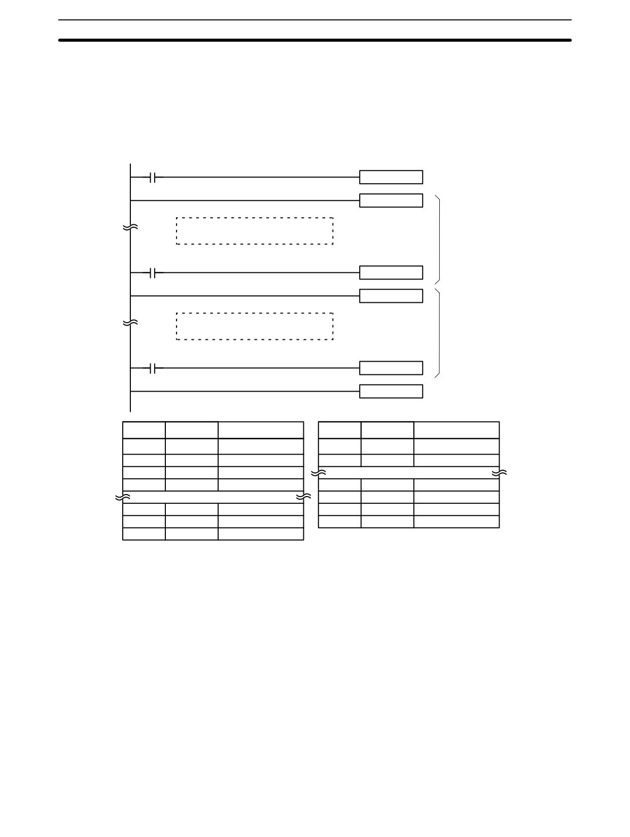
Step Instructions
Section
7-14
Execution of a step is completed either by execution of the next SNXT(09) or by
turning OFF the control bit for the step (see example 3 below). When the step is
completed, all of the IR and HR bits in the step are turned OFF and all timers in
the step are reset to their SVs. Counters, shift registers, and bits used in
KEEP(11) maintain status. Two simple steps are shown below.
00000
SNXT(09) LR 1005
Starts step execution
STEP(08) LR 1005
Step controlled by LR 1005
1st step
00001
SNXT(09) 20200
STEP(08) 20200
Step controlled by IR 20200
2nd step
00002
SNXT(09) 23000
STEP(08)
Ends step execution
Address
Instruction
Operands
Address
Instruction
Operands
00000
LD
00000
00102
STEP(08)
20200
00001
SNXT(09)
LR
1005
00002
STEP(08)
LR
1005
Step controlled by IR 20200.
Step controlled by LR 1005.
00200
LD
00002
00201
SNXT(09)
23000
00100
LD
00001
00202
STEP(08)
---
00101
SNXT(09)
20200
Steps can be programmed in consecutively. Each step must start with STEP(08)
and generally ends with SNXT(09) (see example 3, below, for an exception).
When steps are programmed in series, three types of execution are possible:
sequential, branching, or parallel. The execution conditions for, and the position-
ing of, SNXT(09) determine how the steps are executed. The three examples
given below demonstrate these three types of step execution.
Precautions
Interlocks, jumps, SBN(92), and END(01) cannot be used within step programs.
Bits used as control bits must not be used anywhere else in the program unless
they are being used to control the operation of the step (see example 3, below).
All control bits must be in the same word and must be consecutive.
If IR or LR bits are used for control bits, their status will be lost during any power
interruption. If it is necessary to maintain status to resume execution at the same
step, HR bits must be used.
383
Timer and Counter Instructions
Section
7-15
Flags
25407: Step Start Flag; turns ON for one cycle when STEP(08) is executed and
can be used to reset counters in steps as shown below if necessary.
00000
SNXT(09) 20000
Start
20000
STEP(08) 20000
00100
CP
CNT 001
25407
25407
R
#0003
1 cycle
Address
Instruction
Operands
Address
Instruction
Operands
00000
LD
00000
00004
LD
25407
00001
SNXT(09)
20000
00005
CNT
01
00002
STEP(08)
20000
#
0003
00003
LD
00100
7-15
Timer and Counter Instructions
TIM and TIMH(15) are decrementing ON-delay timer instructions which require
a TC number and a set value (SV). STIM(69) is used to control the interval tim-
ers, which are used to activate interrupt routines.
CNT is a decrementing counter instruction and CNTR(12) is a reversible counter
instruction. Both require a TC number and a SV. Both are also connected to mul-
tiple instruction lines which serve as an input signal(s) and a reset. CTBL(63),
INT(89), and PRV(62) are used to manage the high-speed counter. INT(89) is
also used to stop pulse output.
Any one TC number cannot be defined twice, i.e., once it has been used as the
definer in any of the timer or counter instructions, it cannot be used again. Once
defined, TC numbers can be used as many times as required as operands in
instructions other than timer and counter instructions.
TC numbers run from 000 through 255 in the CPM2A/CPM2C PCs and from 000
through 127 in the CPM1/CPM1A/SRM1(-V2) PCs. No prefix is required when
using a TC number as a definer in a timer or counter instruction. Once defined as
a timer, a TC number can be prefixed with TIM for use as an operand in certain
instructions. The TIM prefix is used regardless of the timer instruction that was
used to define the timer. Once defined as a counter, a TC number can be pre-
fixed with CNT for use as an operand in certain instructions. The CNT is also
used regardless of the counter instruction that was used to define the counter.
TC numbers can be designated as operands that require either bit or word data.
When designated as an operand that requires bit data, the TC number accesses
a bit that functions as a ‘Completion Flag’ that indicates when the time/count has
expired, i.e., the bit, which is normally OFF, will turn ON when the designated SV
has expired. When designated as an operand that requires word data, the TC
number accesses a memory location that holds the present value (PV) of the
timer or counter. The PV of a timer or counter can thus be used as an operand in
CMP(20), or any other instruction for which the TC area is allowed. This is done
by designating the TC number used to define that timer or counter to access the
memory location that holds the PV.
384
Timer and Counter Instructions
Section
7-15
Note that “TIM 000” is used to designate the TIMER instruction defined with TC
number 000, to designate the Completion Flag for this timer, and to designate
the PV of this timer. The meaning of the term in context should be clear, i.e., the
first is always an instruction, the second is always a bit operand, and the third is
always a word operand. The same is true of all other TC numbers prefixed with
TIM or CNT.
An SV can be input as a constant or as a word address in a data area. If an IR
area word assigned to an Input Unit is designated as the word address, the Input
Unit can be wired so that the SV can be set externally through thumbwheel
switches or similar devices. Timers and counters wired in this way can only be
set externally during RUN or MONITOR mode. All SVs, including those set ex-
ternally, must be in BCD.
7-15-1 TIMER - TIM
Definer Values
N: TC number
Ladder Symbol
#
TIM
N
SV
Operand Data Areas
SV: Set value (word, BCD)
IR, SR, AR, DM, HR, LR, #
SV is between 000.0 and 999.9. The decimal point is not entered.
Limitations
Each TC number can be used as the definer in only one TIMER or COUNTER
instruction. TC numbers run from 000 through 255 in the CPM2A/CPM2C PCs
and from 000 through 127 in the CPM1/CPM1A/SRM1(-V2) PCs.
TC 000 through TC 003 (TC 000 through TC 015 in the CPM2A/CPM2C) should
not be used in TIM if they are required for TIMH(15). Refer to 7-15-2 HIGH-
SPEED TIMER - TIMH(15) for details.
In the CPM2A/CPM2C PCs, TC 004 through TC 007 should not be used in TIM if
they are required for TMHH(--). Refer to 7-15-3 VERY HIGH-SPEED TIMER -
TMHH(--) for details.
Description
A timer is activated when its execution condition goes ON and is reset (to SV)
when the execution condition goes OFF. Once activated, TIM measures in units
of 0.1 second from the SV.
If the execution condition remains ON long enough for TIM to time down to zero,
the Completion Flag for the TC number used will turn ON and will remain ON
until TIM is reset (i.e., until its execution condition is goes OFF).
The following figure illustrates the relationship between the execution condition
for TIM and the Completion Flag assigned to it.
ON
Execution condition
OFF
ON
Completion Flag
OFF
SV
SV
Timers in interlocked program sections are reset when the execution condition
Precautions
for IL(02) is OFF. Power interruptions also reset timers. If a timer that is not reset
under these conditions is desired, SR area clock pulse bits can be counted to
produce timers using CNT. Refer to 7-15-5 COUNTER - CNT for details.
385
Timer and Counter Instructions
Section
7-15
The Completion Flag may be turned ON one cycle late when reading its status
from the user program.
Always reset the timer after changing between TIM and TIMH(015) in online
editing. The timer will not work properly if it is not reset.
If the timer’s set value is set to 0000, the Completion Flag will turn ON as soon as
the timer’s execution condition turns ON. If the timer’s set value is set to 0001,
the Completion Flag will turn ON somewhere between 0 and 0.1 s after the tim-
er’s execution condition turns ON (i.e., the timer accuracy will actually determine
the time), and may turn ON as soon as the timer’s execution condition turns ON.
Always consider the accuracy of the timer (0 to -0.1 s) in application programs.
Flags
ER:
Indirectly addressed DM word is non-existent. (Content of *DM word is
not BCD, or the DM area boundary has been exceeded.)
7-15-2 HIGH-SPEED TIMER - TIMH(15)
Definer Values
N: TC number
Ladder Symbol
#
TIMH(15) N
SV
Operand Data Areas
SV: Set value (word, BCD)
IR, SR, AR, DM, HR, LR, #
Limitations
SV is between 00.00 and 99.99. (Although 00.00 and 00.01 may be set, 00.00
will disable the timer, i.e., turn ON the Completion Flag immediately, and 00.01 is
not reliably scanned.) The decimal point is not entered.
Each TC number can be used as the definer in only one TIMER or COUNTER
instruction. TC numbers run from 000 through 255 in the CPM2A/CPM2C PCs
and from 000 through 127 in the CPM1/CPM1A/SRM1(-V2) PCs.
Description
TIMH(15) operates in the same way as TIM except that TIMH measures in units
of 0.01 second. Refer to 7-15-1 TIMER - TIM for operational details.
Precautions
Timers in interlocked program sections are reset when the execution condition
for IL(02) is OFF. Power interruptions also reset timers. If a timer that is not reset
under these conditions is desired, SR area clock pulse bits can be counted to
produce timers using CNT. Refer to 7-15-5 COUNTER - CNT for details.
Timers in jumped program sections will not be reset when the execution condi-
tion for JMP(04) is OFF. The timer will stop timing if jump number 00 is used, but
will continue timing if other jump numbers are used.
Always reset the timer when changing between TIM and TIMH(15) in online edit-
ing. Also, when changing a TIMH(15) instruction with interrupt refreshing, do so
only in PROGRAM mode.
Use timer numbers 000 to 003 for TIMH(15). High-speed timers with timer num-
bers TC 004 through TC 127 (TC 016 through TC 255 in the CPM2A/CPM2C)
may not be accurate when the cycle time exceeds 10 ms.
PC
Interrupt refreshing every
Refreshed when TIMH(015)
10 ms
is executed
CPM2A/CPM2C
TC 000 through TC 003
TC 004 through TC 255
CPM1, CPM1A, and
TC 000 through TC 003
TC 004 through TC 127
SRM1(-V2)
386
Timer and Counter Instructions
Section
7-15
In the CPM2A/CPM2C PCs, TC 004 through TC 007 should not be used in
TIMH(15) if they are required for TMHH(--). Refer to 7-15-3 VERY HIGH-
SPEED TIMER - TMHH(--) for details.
If the timer’s set value is set to 0000, the Completion Flag will turn ON as soon as
the timer’s execution condition turns ON. If TIM000 to TIM003 are used, howev-
er, there may be a delay before the flag turns ON.
If the timer’s set value is set to 0001, the Completion Flag will turn ON some-
where between 0 and 0.01 s after the timer’s execution condition turns ON (i.e.,
the timer accuracy will actually determine the time), and may turn ON as soon as
the timer’s execution condition turns ON.
Always consider the accuracy of the timer (0 to -0.01 s) in application programs.
Flags
ER:
Indirectly addressed DM word is non-existent. (Content of *DM word is
not BCD, or the DM area boundary has been exceeded.)
Example
The following example shows a timer set with a constant. CIO 01600 will be
turned ON after CIO 00000 goes ON and stays ON for at least 1.5 seconds.
When 00000 goes OFF, the timer will be reset and CIO 01600 will be turned OFF.
00000
Address
Instruction
Operands
TIMH(15)
000
1.5 s
00000
LD
00000
#0150
00001
TIMH(15)
000
TIM 000
#
0150
01600
00002
LD
TIM
000
00003
OUT
01600
7-15-3 VERY HIGH-SPEED TIMER: TMHH(--)
Ladder Symbol
Operand Data Areas
N: #
TMHH(--)
TIM000 to TIM255
N
SV: Set value
SV
IR, SR, AR, DM, HR, LR, #
000
000
Set to 000.
This instruction is supported by the CPM2A/CPM2C only.
Limitations
Each TC number can be used as the definer in only one TIMER or COUNTER
instruction. TC numbers run from TIM000 through TIM255. (You must enter
“TIM” along with the actual timer number when using TIML(--). The instruction
will not work if only the number is entered.)
SV is BCD between 0000 and 9999 (0 to 9.999 s).
Set the third operand to 000. (This operand is ignored.)
Description
TMHH(--) is a decrementing ON-delay timer that times in 1-ms units. The timer
set value can be 0 to 9.999 s and the timer has a accuracy of 1 ms.
A very high-speed timer is activated when its execution condition goes ON and is
reset (to the SV) when the execution condition goes OFF. Once activated,
TMHH(--) times down from the SV in units of 1 ms.
The timer will time out when the PV reaches #0000 (0 ms). Once the timer has
timed out, the PV and Completion Flag status will be maintained. The timer can
be restarted by temporarily turning its execution condition from ON to OFF or
387
Timer and Counter Instructions
Section
7-15
changing its PV to a value other than #0000 with an instruction such as
MOV(21).
The operation of very high-speed timers in jumped program sections depends
upon the TC number used to define the timer, as shown in the following table.
TC number
Operation
000 to 003,
The timer will stop when the execution condition for JMP(04) is OFF.
008 to 255
This can greatly reduce the accuracy of timers in jumped program
sections.
004 to 007
If jump number 00 is used, the timer will stop timing when the
execution condition for JMP(04) is OFF. This can greatly reduce the
accuracy of timers in jumped program sections.
If any other jump number is used, the timer will continue timing
normally when the execution condition for JMP(04) is OFF.
Precautions
Very high-speed timers with timer numbers other than TC 004 through TC 007
may not be accurate when the cycle time exceeds 1 ms. (The cycle time will not
affect very high-speed timers defined with TC 004 through TC 007.)
Very high-speed timers in interlocked program sections are reset (to the SV)
when the execution condition for IL(02) is OFF.
If the timer’s set value is set to 0000, the Completion Flag will turn ON as soon as
the timer’s execution condition turns ON. If TIM004 to TIM007 are used, howev-
er, there may be a delay before the flag turns ON.
If the timer’s set value is set to 0001, the Completion Flag will turn ON some-
where between 0 and 1 ms after the timer’s execution condition turns ON (i.e.,
the timer accuracy will actually determine the time), and may turn ON as soon as
the timer’s execution condition turns ON.
Always consider the accuracy of the timer (0 to -1 ms) in application programs.
Flags
ER:
N is not a valid TC number.
Example
In the following example, CIO 20000 will be turned ON after CIO 00000 goes ON
and stays ON for at least 1.5 seconds. When 00000 goes OFF, the timer will be
reset and CIO 20000 will be turned OFF.
00000
Address
Instruction
Operands
TMHH(--)
00000
LD
00000
TIM004
00001
TMHH(--)
#1500
1.5 s
TIM
004
000
#
1500
000
TIM004
00002
LD
TIM
004
20000
00003
OUT
20000
7-15-4 LONG TIMER: TIML(--)
Ladder Symbol
Operand Data Areas
N: Timer number (see Limitations)
TIML(--)
TIM000 to TIM255
N
SV: Set value
SV
IR, SR, AR, DM, HR, LR, #
C
C: Control data
000 or 001
This instruction is supported by the CPM2A/CPM2C only.
388
Timer and Counter Instructions
Section
7-15
Each timer number can be used as the definer in only one TIMER or COUNTER
Limitations
instruction. Timer numbers run from TIM000 through TIM255. (You must enter
“TIM” along with the actual timer number when using TIML(--). The instruction
will not work if only the number is entered.)
SV is BCD between 0000 and 9999 (0 to 9,999 s when C=000 and 0 to 99,990 s
when C=001).
C must be 000 (1-s timing units) or 001 (10-s timing units).
TIML(--) is a decrementing ON-delay timer that can time in 1-s units or 10-s
Description
units. The timer set value can be 0 to 9,999 s (accuracy 0 to 1 s) when 1-s units
are used (C=000) or 0.10 to 99,990 s (accuracy 0 to 10 s) when 10-s units are
used (C=001).
A long timer is activated when its execution condition goes ON and is reset (to
the SV) when the execution condition goes OFF. Once activated, TIML(--)
times down from the SV in units of 1 s or 10 s (depending upon the value of C).
TIML(--) accuracy is 0 to 1 s with 1-s units or 0 to 10 s with 10-s units.
The timer will time out when the PV reaches #0000 (0 s). Once the timer has
timed out, the PV and Completion Flag status will be maintained. The timer can
be restarted by temporarily turning its execution condition from ON to OFF or
changing its PV to a value other than #0000 with an instruction such as
MOV(21).
Long timers in jumped program sections will not be reset when the execution
condition for JMP(04) is OFF, but the timer will stop timing and the PV will be
maintained. Timing will resume when the execution condition for JMP(04) goes
ON again. This can greatly reduce the accuracy of long timers in jumped pro-
gram sections.
Precautions
TIML(--) may not be accurate when the cycle time exceeds 1 s (C=000) or 10 s
(C=001).
Long timers in interlocked program sections are reset (to the SV) when the
execution condition for IL(02) is OFF.
The timing units in C can be changed while the long timer is timing. Changing the
timing units during operation reduces the timer’s accuracy by up to 10 s.
You must enter “TIM” along with the actual timer number when using TIML(--).
The instruction will not work if only the number is entered.
If the timer’s set value is set to 0000, the Completion Flag will turn ON as soon as
the timer’s execution condition turns ON. If the timer’s set value is set to 0001,
the Completion Flag will turn ON somewhere between 0 and 1 s or between 0
and 10 s after the timer’s execution condition turns ON (i.e., the timer accuracy
will actually determine the time), and may turn ON as soon as the timer’s execu-
tion condition turns ON.
Always consider the accuracy of the timer (0 to -1 s or 0 to -10 s) in application
programs.
Flags
ER:
N is not a valid timer number.
C is not 000 or 001.
389
Timer and Counter Instructions
Section
7-15
Example
In the following example, CIO 20000 will be turned ON after CIO 00000 goes ON
and stays ON for at least 1,500 seconds. When 00000 goes OFF, the timer will
be reset and CIO 20000 will be turned OFF.
00000
Address
Instruction
Operands
TIML(--)
00000
LD
00000
TIM002
00001
TIML(--)
#0150
1500 s
TIM
002
001
#
0150
001
TIM002
00002
LD
TIM
002
20000
00003
OUT
20000
7-15-5 COUNTER - CNT
Definer Values
N: TC number
Ladder Symbol
#
CP
CNT N
R
SV
Operand Data Areas
SV: Set value (word, BCD)
IR, SR, AR, DM, HR, LR, #
Each TC number can be used as the definer in only one TIMER or COUNTER
Limitations
instruction. TC numbers run from 000 through 255 in the CPM2A/CPM2C PCs
and from 000 through 127 in the CPM1/CPM1A/SRM1(-V2) PCs.
Description
CNT is used to count down from SV when the execution condition on the count
pulse, CP, goes from OFF to ON, i.e., the present value (PV) will be decrem-
ented by one whenever CNT is executed with an ON execution condition for CP
and the execution condition was OFF for the last execution. If the execution
condition has not changed or has changed from ON to OFF, the PV of CNT will
not be changed. The Completion Flag for a counter is turned ON when the PV
reaches zero and will remain ON until the counter is reset.
CNT is reset with a reset input, R. When R goes from OFF to ON, the PV is reset
to SV. The PV will not be decremented while R is ON. Counting down from SV will
begin again when R goes OFF. The PV for CNT will not be reset in interlocked
program sections or by power interruptions.
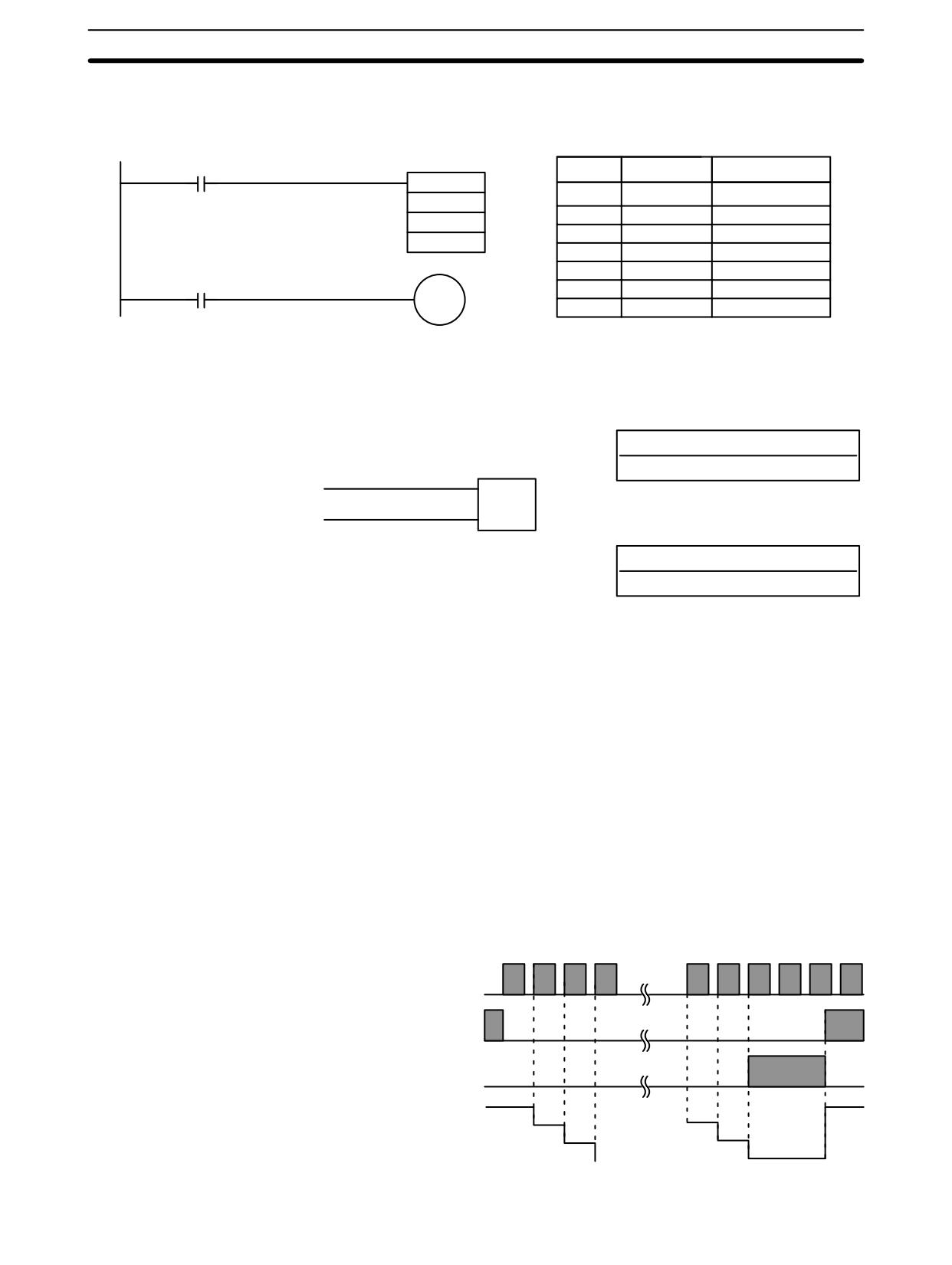
Changes in execution conditions, the Completion Flag, and the PV are illus-
trated below. PV line height is meant only to indicate changes in the PV.
Execution condition
ON
on count pulse (CP)
OFF
Execution condition
ON
on reset (R)
OFF
ON
Completion Flag
OFF
SV
SV
PV
0002
SV - 1
0001
SV - 2
0000
390
Timer and Counter Instructions
Section 7-15
Program execution will continue even if a non-BCD SV is used, but the SV will
Precautions
not be correct.
Flags
ER:
Indirectly addressed DM word is non-existent. (Content of *DM word is
not BCD, or the DM area boundary has been exceeded.)
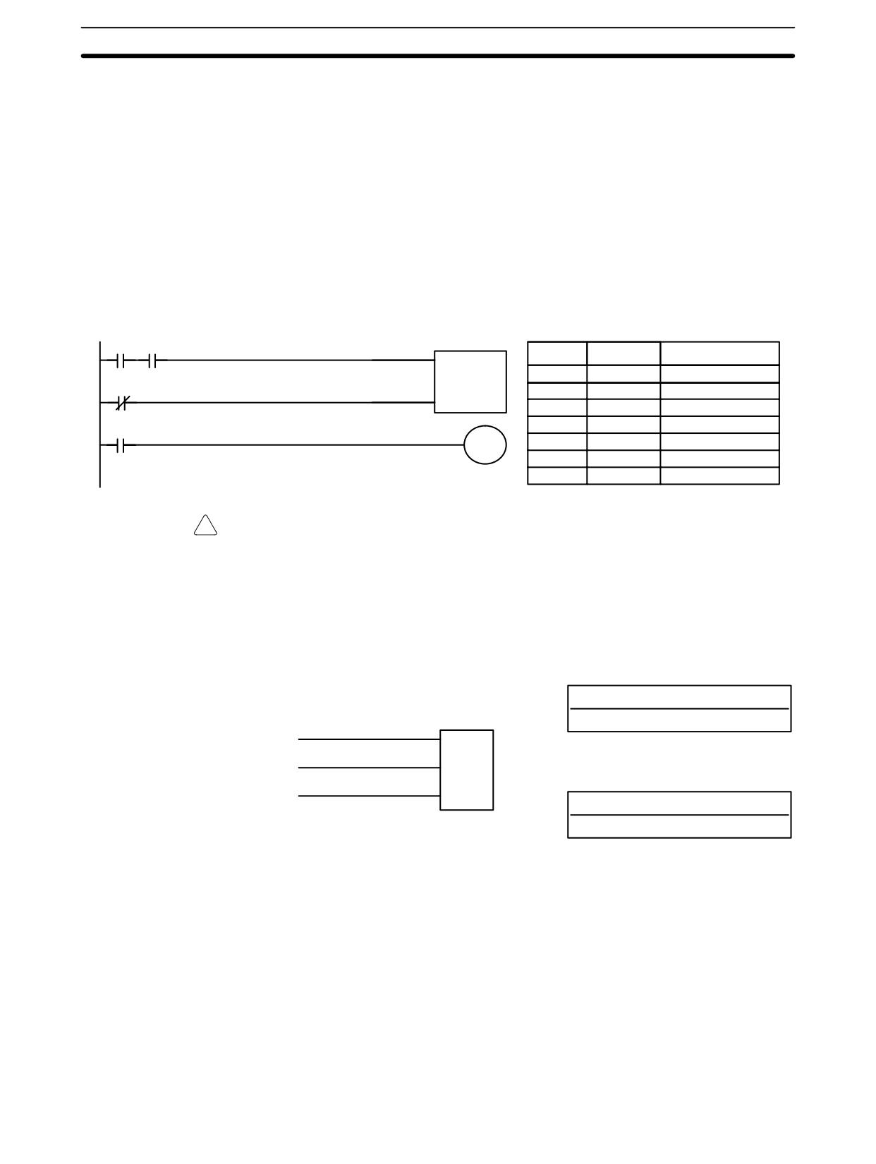
Example
In the following example, CNT is used to create extended timers by counting SR
area clock pulse bits.
CNT 001 counts the number of times the 1-second clock pulse bit (SR 25502)
goes from OFF to ON. Here again, IR 00000 is used to control the times when
CNT is operating.
Because in this example the SV for CNT 001 is 700, the Completion Flag for
CNT 002 turns ON when 1 second x 700 times, or 11 minutes and 40 seconds
have expired. This would result in IR 20002 being turned ON.
00000
25502
CP
Address
Instruction
Operands
CNT
00000
LD
00000
001
00001
00001
AND
25502
R
#0700
00002
LD NOT
00001
00003
CNT
001
CNT 001
20002
#
0700
00004
LD
CNT
001
00005
OUT
20002
!
Caution The shorter clock pulses will not necessarily produce accurate timers because
their short ON times might not be read accurately during longer cycles. In partic-
ular, the 0.02-second and 0.1-second clock pulses should not be used to create
timers with CNT instructions.
7-15-6 REVERSIBLE COUNTER - CNTR(12)
Definer Values
N: TC number
Ladder Symbol
#
II
CNTR(12)
DI
N
Operand Data Areas
SV
R
SV: Set value (word, BCD)
IR, SR, AR, DM, HR, LR, #
Each TC number can be used as the definer in only one TIMER or COUNTER
Limitations
instruction. TC numbers run from 000 through 255 in the CPM2A/CPM2C PCs
and from 000 through 127 in the CPM1/CPM1A/SRM1(-V2) PCs.
Description
The CNTR(12) is a reversible, up/down circular counter, i.e., it is used to count
between zero and SV according to changes in two execution conditions, those in
the increment input (II) and those in the decrement input (DI).
The present value (PV) will be incremented by one whenever CNTR(12) is
executed with an ON execution condition for II and the last execution condition
for II was OFF. The present value (PV) will be decremented by one whenever
CNTR(12) is executed with an ON execution condition for DI and the last execu-
tion condition for DI was OFF. If OFF to ON changes have occurred in both II and
DI since the last execution, the PV will not be changed.
391
Timer and Counter Instructions
Section
7-15
If the execution conditions have not changed or have changed from ON to OFF
for both II and DI, the PV of CNT will not be changed.
When decremented from 0000, the present value is set to SV and the Comple-
tion Flag is turned ON until the PV is decremented again. When incremented
past the SV, the PV is set to 0000 and the Completion Flag is turned ON until the
PV is incremented again.
CNTR(12) is reset with a reset input, R. When R goes from OFF to ON, the PV is
reset to zero. The PV will not be incremented or decremented while R is ON.
Counting will begin again when R goes OFF. The PV for CNTR(12) will not be
reset in interlocked program sections or by the effects of power interruptions.
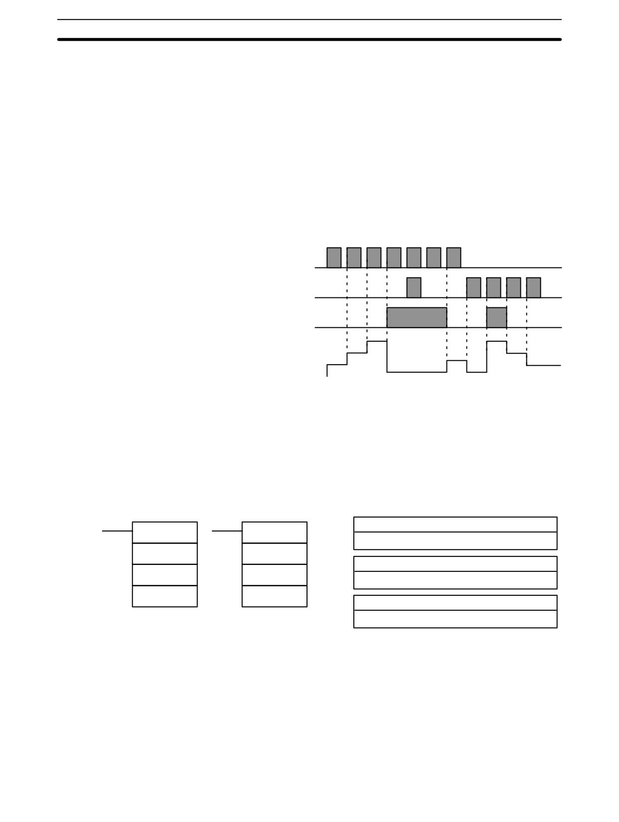
Changes in II and DI execution conditions, the Completion Flag, and the PV are
illustrated below starting from part way through CNTR(12) operation (i.e., when
reset, counting begins from zero). PV line height is meant to indicate changes in
the PV only.
Execution condition
ON
on increment (II)
OFF
Execution condition
ON
on decrement (DI)
OFF
ON
Completion Flag
OFF
SV
SV
PV
SV - 1
SV - 1
0001
SV - 2
SV - 2
0000
0000
Program execution will continue even if a non-BCD SV is used, but the SV will
Precautions
not be correct.
Flags
ER:
Indirectly addressed DM word is non-existent. (Content of *DM word is
not BCD, or the DM area boundary has been exceeded.)
7-15-7
REGISTER COMPARISON TABLE - CTBL(63)
Ladder Symbols
Operand Data Areas
P: Port specifier
CTBL(63)
@CTBL(63)
000
P
P
C: Control data
C
C
000 to 003
TB
TB
TB: First comparison table word
IR, SR, AR, DM, HR, LR
This instruction is not supported by SRM1(-V2) PCs.
Limitations
The first and last comparison table words must be in the same data area. (The
length of the comparison table varies according to the settings.)
P must be 000 and C must be between 000 and 003.
Description
When the execution condition is OFF, CTBL(63) is not executed. When the
execution condition is ON, CTBL(63) registers a comparison table for use with
the high-speed counter PV. Depending on the value of C, comparison with the
high-speed counter PV can begin immediately or it can be started separately
with INI(61).
392
Timer and Counter Instructions
Section
7-15
The port specifier (P) specifies the high-speed counter that will be used in the
comparison. Always set P to 000.
The function of CTBL(63) is determined by the control data, C, as shown in the
following table. These functions are described after the table.
C
CTBL(63) function
000
Registers a target value comparison table and starts comparison.
001
Registers a range comparison table and starts comparison.
002
Registers a target value comparison table. Start comparison with INI(61).
003
Registers a range comparison table. Start comparison with INI(61).
When the PV agrees with a target value or falls within a specified range, the spe-
cified subroutine is called and executed. Refer to 2-3-5 High-speed Counter In-
terrupts for more details on table comparison.
If the high-speed counter is enabled in the PC Setup (DM 6642), it will begin
counting from zero when the CPM2A/CPM2C begins operation. The PV will not
be compared to the comparison table until the table is registered and compari-
son is initiated with INI(61) or CTBL(63). Comparison can be stopped and
started, or the PV can be reset with INI(61).
Common Characteristics
The operation of a target value comparison is different from a range comparison,
of Target Value and
but the two functions share some common characteristics.
Range Comparisons
1, 2, 3...
1. Subroutine numbers 000 to 049 can be used and the same subroutine num-
ber can be used more than once in the table.
2. An undefined subroutine number or FFFF can be set for the subroutine
number if interrupt processing is not required.
3. Comparison can be stopped with INI(61). A registered table is valid until PC
operation stops or a new comparison table is registered.
4. CTBL(62) cannot be executed if the high-speed counter is disabled in the
PC Setup (DM 6642). (An error will occur if CTBL(63) is executed when the
high-speed counter is disabled.)
Target Value Comparison
A target value comparison table contains up to sixteen target values. A subrou-
tine number is also registered for each target value. The corresponding subrou-
tine is called and executed when the PV matches a target value. (When interrupt
processing is not required, an undefined subroutine number may be entered.)
• In the CPM1/CPM1A, target value comparisons are performed one item at a
time in order of the comparison table. When the PV reaches the first target val-
ue in the table, the interrupt subroutine is executed and comparison continues
to the next value in the table. When processing has been completed for the last
target value in the table, comparison returns to the first value in the table and
the process is repeated.
• In the CPM2A/CPM2C, the PV is compared to all of the target values in the
table each time CTBL(63) is executed. When the PV matches a target value
the corresponding subroutine is called and executed.
The following diagram shows the structure of a target value comparison table.
Target values must be unique; an error will occur if a target value appears in the
table more than once.
TB
Number of target values (0001 to 0016, BCD)
TB+1
Target value #1, lower 4 digits (BCD)
TB+2
Target value #1, upper 4 digits (BCD)
One target
value setting
TB+3
Subroutine number for #1 (See note.)
393
Timer and Counter Instructions
Section
7-15
Note
The subroutine number can be F000 to F049 to activate the subroutine when
decrementing and can be 0000 to 0049 to activate the subroutine when incre-
menting. An error will occur if the high-speed counter is set to increment mode
but a decrementing subroutine number (F000 to F049) is specified.
Range Comparison
A range comparison table contains 8 ranges which are defined by an 8-digit low-
er limit and an 8-digit upper limit, as well as their corresponding subroutine num-
bers. The comparison is performed once each cycle at the end of program exe-
cution and can be performed during program execution with INI(61).
When the PV falls within a given range the corresponding subroutine is called
and executed. (When interrupt processing is not required, an undefined subrou-
tine number may be entered.) Ranges can overlap, so the PV can fall within
more than one range; in the PV is within two or more ranges, the subroutine for
the first of the ranges will be executed.
The following diagram shows the structure of a range comparison table. Always
set 8 ranges. If fewer than 8 ranges are needed, set the remaining subroutine
numbers to FFFF.
TB
Lower limit #1, lower 4 digits (BCD)
TB+1
Lower limit #1, upper 4 digits (BCD)
TB+2
Upper limit #1, lower 4 digits (BCD)
First range setting
TB+3
Upper limit #1, upper 4 digits (BCD)
TB+4
Subroutine number (See note 2.)
TB+35
Lower limit #8, lower 4 digits (BCD)
TB+36
Lower limit #8, upper 4 digits (BCD)
TB+37
Upper limit #8, lower 4 digits (BCD)
Eighth range setting
TB+38
Upper limit #8, upper 4 digits (BCD)
TB+39
Subroutine number (See note 2.)
Note
1. Each range’s lower limit must be less than its upper limit. An error will occur if
the lower limit is greater than the upper limit.
2. The subroutine number can be 0000 to 0049 and the subroutine will be exe-
cuted as long as the counter’s PV is within the specified range. A value of
FFFF indicates that no subroutine is to be executed.
3. Since the comparison is usually performed just once each cycle, be sure to
take the cycle time into account when the upper and lower limits represent
time values.
4. A subroutine number can be used more than once in the table.
Flags
ER:
The comparison table exceeds the data area boundary, or there is an
error in the comparison table settings.
Indirectly addressed DM word is non-existent. (Content of *DM word is
not BCD, or the DM area boundary has been exceeded.)
P is not 000 or C is not between 000 and 003.
There is a CTBL(63) instruction using a different comparison format in
the subroutine called by another CTBL(63) instruction.
A CTBL(63) instruction using a different comparison format is executed
during comparison.
CTBL(63) is executed in an interrupt subroutine while a pulse I/O or
high-speed counter instruction (INI(61), PRV(62), CTBL(63),
SPED(64), PULS(65), ACC(--), PWM(--), or SYNC(--)) is being
executed in the main program.
394
Timer and Counter Instructions
Section
7-15
Target Value Comparison Errors:
The number of target values (in TB) is not between 0001 and 0016.
A target value is not between F838 8608 and 0838 8607 (differential
phase mode, pulse + direction input mode, and up/down input mode).
A target value is not between 0000 0001 and 1677 7215 or a subroutine
number is not between 0000 and 0049 (increment mode).
If 0000 0000 is set in increment mode, 25503 (ER) will turn ON and the
instruction will not be executed.
Range Comparison Errors:
A range’s upper limit value is less than its lower limit value.
A target value is not between F838 8608 and 0838 8607 (differential
phase mode, pulse + direction input mode, and up/down input mode).
A target value is not between 0000 0000 and 1677 7215 or a subroutine
number is not between 0000 and 0049 (increment mode).
7-15-8
MODE CONTROL - INI(61)
Ladder Symbols
Operand Data Areas
P: Port specifier
INI(61)
@INI(61)
000, 010, 100, 101, 102, 103
P
P
C: Control data
C
C
000 to 005
P1
P1
P1: First PV word
IR, SR, AR, DM, HR, LR (or 000)
This instruction is not supported by SRM1(-V2) PCs.
Limitations
In the CPM1/CPM1A PCs, P must be 000 and C must be 000 to 003.
In CPM2A/CPM2C PCs, P must be 000, 010, 100, 101, 102, or 103 and C must
be 000 to 005.
P1 must be 000 unless C is 002 or 004.
P1 and P1+1 must be in the same data area.
If a DM address is used for P1, it must be read/write DM.
Description
When the execution condition is OFF, INI(61) is not executed. When the execu-
tion condition is ON, INI(61) is used to control high-speed counter operation and
stop pulse output.
The port specifier (P) specifies the high-speed counter or pulse output that will
be controlled.
P
Function
000
Specifies high-speed counter input (inputs 00000, 00001, and 00002),
single-phase pulse output 0 with no acceleration/deceleration (output
01000 or 01001), single-phase pulse output 0 with trapezoidal accelera-
tion/deceleration (output 01000).
010*
Specifies single-phase pulse output 1 with no acceleration/deceleration
(output 01001).
100*
Specifies interrupt input 0 in counter mode (input 00003).
101*
Specifies interrupt input 1 in counter mode (input 00004).
102*
Specifies interrupt input 2 in counter mode (input 00005).
103*
Specifies interrupt input 3 in counter mode (input 00006).
Note *These settings can be used in CPM2A/CPM2C PCs only.
395

Timer and Counter Instructions
Section
7-15
The function of INI(61) is determined by the control data, C.
C
P1
INI(61) function
000
000
Starts CTBL(63) table comparison.
001
000
Stops CTBL(63) table comparison.
002
New PV
Changes PV of the high-speed counter or an interrupt input in
counter mode.
003
000
Stops pulse output.
004*
New PV
Changes PV of the pulse output.
005*
000
Stops synchronized pulse control output.
Note
*These settings can be used in CPM2A/CPM2C PCs only.
Start or Stop Comparison
If C is 000 or 001, INI(61) starts or stops comparison of the high-speed counter’s
(C=000 or C=001)
PV to the comparison table registered with CTBL(63). An error will occur if this
function is executed without first registering a comparison table with CTBL(63).
In general, @INI(61) should be used when C=000 because the instruction
needs to be executed only one time to start table comparison.
Change PV
If C is 002, INI(61) changes the PV of the specified high-speed counter or inter-
(C=002)
rupt input (counter mode).
High-speed Counter PV (P=000)
INI(61) changes the PV of the specified high-speed counter to the 8-digit BCD
value in P1 and P1+1.
The new PV can be F838 8608 to 0838 8607 in differential phase mode, pulse +
direction input mode, or up/down input mode. (The hexadecimal “F” in the first
digit acts as a minus sign.)
The new PV can be 0000 0000 to 1677 7215 in increment mode.
Interrupt Input PV (P=100 to 103)
INI(61) changes the PV of the specified interrupt input (counter mode) to the
4-digit hexadecimal value (0000 to FFFF) in P1.
Stop Pulse Output
If C is 003, INI(61) stops the pulse output.
(C=003)
Change PV
INI(61) changes the PV of the pulse output to the 8-digit BCD value in P1 and
(C=004)
P1+1. The PV cannot be changed while the pulse output is in progress.
The new PV can be -16,777,215 to 16,777,215. Bit 15 of P1+1 acts as a sign bit;
the number is negative if bit 15 is ON, positive if it is OFF.
If C is 003, INI(61) stops the synchronized pulse control output.
Stop Synchronized Pulse
Control Output (C=003)
Flags
ER:
The port specifier and control data are incompatible.
(For example: P=010 and C=000)
There is an error in the operand settings or the specified PV is not within
the acceptable range.
The address specified for P1 or P1+1 exceeds the data area boundary.
Indirectly addressed DM word is non-existent. (Content of *DM word is
not BCD, or the DM area boundary has been exceeded.)
The specified function is incompatible with actual PC operation. For ex-
ample, do not set C=005 if synchronized pulse control is not being used.
INI(61) is executed to change the PV of a pulse output (C=004) while the
pulse output is operating.
INI(61) is executed in an interrupt subroutine while a pulse I/O or high-
speed counter instruction (INI(61), PRV(62), CTBL(63), SPED(64),
PULS(65), ACC(--), PWM(--), or SYNC(--)) is being executed in the
main program.
396
Timer and Counter Instructions
Section
7-15
INI(61) is executed in an interrupt subroutine while a pulse I/O or high-
speed counter instruction is being executed in the main program.
7-15-9
HIGH-SPEED COUNTER PV READ - PRV(62)
Ladder Symbols
Operand Data Areas
P: Port specifier
PRV(62)
@PRV(62)
000, 010, 100, 101, 102, 103
P
P
C: Control data
C
C
000, 001, 002, or 003
D
D
D: First destination word
IR, SR, AR, DM, HR, LR
This instruction is not supported by SRM1(-V2) PCs.
Limitations
In the CPM1/CPM1A PCs, P must be 000 and C must be 000 to 002.
In CPM2A/CPM2C PCs, P must be 000, 010, 100, 101, 102, or 103 and C must
be 000 to 003.
D and D+1 must be in the same data area.
If a DM address is used for D, it must be read/write DM.
Description
When the execution condition is OFF, PRV(62) is not executed. When the
execution condition is ON, PRV(62) controls the high-speed counter PV, pulse
output PV, interrupt input (counter mode) PV, or input frequency for synchro-
nized control as specified by P and C.
The port specifier (P) specifies the high-speed counter or pulse output that will
be controlled.
P
Function
000
Specifies high-speed counter input (inputs 00000, 00001, and 00002), in-
put frequency for synchronized pulse control (inputs 00000, 00001, and
00002), single-phase pulse output 0 with no acceleration/deceleration (out-
puts 01000 and 01001), single-phase pulse output 0 with trapezoidal ac-
celeration/deceleration (output 01000), or synchronized pulse control out-
put 0 (output 01000/01001).
010*
Specifies single-phase pulse output 1 with no acceleration/deceleration
(output 01001) or synchronized pulse control output 1 (output 01001).
100*
Specifies interrupt input 0 in counter mode (input 00003).
101*
Specifies interrupt input 1 in counter mode (input 00004).
102*
Specifies interrupt input 2 in counter mode (input 00005).
103*
Specifies interrupt input 3 in counter mode (input 00006).
Note
*These settings can be used in CPM2A/CPM2C PCs only.
The control data, C, determines which type of data will be accessed.
C
Function
Destination word(s)
000
Reads the PV of the high-speed counter or interrupt
D and D+1
input (counter mode) or the input frequency of the
synchronized pulse control.
001
Reads the status of the high-speed counter or pulse
D
output.
002
Reads the results of range comparison.
D
003*
Reads the PV of the pulse output.
D and D+1
Note
*This setting can be used in CPM2A/CPM2C PCs only.
397
Timer and Counter Instructions
Section
7-15
If C is 000, PRV(62) reads the PV of the specified high-speed counter or interrupt
Read PV (C=000)
input (counter mode).
High-speed Counter PV or Input Frequency (P=000)
When the output is used for a high-speed counter, PRV(62) reads the PV of the
specified high-speed counter and writes the 8-digit BCD value in D and D+1.
(The leftmost 4 digits are written to D+1.)
The PV can be F838 8608 to 0838 8607 in differential phase mode, pulse + di-
rection input mode, or up/down input mode. (The hexadecimal “F” in the first digit
acts as a minus sign.)
The PV can be 0000 0000 to 1677 7215 in increment mode.
When the output is used for synchronized pulse control, PRV(62) reads the input
frequency and writes the 8-digit BCD value in D and D+1. The input frequency
can be 0000 0000 to 0002 0000.
Interrupt Input PV (P=100 to 103)
PRV(62) reads the PV of the specified interrupt input (counter mode) and writes
the 4-digit hexadecimal value (0000 to FFFF) in D.
Read Status (C=001)
If C is 001, PRV(62) reads the operating status of the specified high-speed
counter or pulse output and writes the data to D.
High-speed Counter or Pulse Output 0 Status (P=000)
The following table shows the function of the bits in D when P=000. Bits not listed
in the table are not used and will always be 0.
Usage
Bit
Function
High-speed
00
High-speed counter comparison status.
counter
(0: Stopped; 1: Comparing)
01
High-speed counter underflow/overflow.
(0: Normal; 1: Underflow/Overflow occurred.)
Pulse output
05
Total number of pulses specified for pulse output 0.
(0: Not specified; 1: Specified.)
06
Pulse output 0 completed. (0: Not completed; 1: Completed)
07
Pulse output 0 status (0: Stopped; 1: Outputting)
08
Pulse output 0 PV underflow/overflow.
(0: Normal; 1: Underflow/Overflow occurred.)
09
Pulse output 0 acceleration
0: Constant; 1: Accelerating or decelerating
Pulse Output 1 Status (P=010)
The following table shows the function of the bits in D when P=010. Bits not listed
in the table are not used and will always be 0.
Bit
Function
05
Total number of pulses specified for pulse output 1.
(0: Not specified; 1: Specified.)
06
Pulse output 1 completed. (0: Not completed; 1: Completed)
07
Pulse output 1 status (0: Stopped; 1: Outputting)
08
Pulse output 1 PV underflow/overflow.
(0: Normal; 1: Underflow/Overflow occurred.)
09
Pulse output 1 acceleration (0: Constant; 1: Accelerating or decelerating)
Read Range Comparison
If C is 002, PRV(62) reads the results of the comparison of the PV to the 8 ranges
Results (C=002)
defined by CTBL(63) and writes this data to D. Bits 00 through 07 of D contain
the Comparison Result Flags for ranges 1 to 8. (0: Not in range; 1: In range)
Read Pulse Output PV
If C is 003, PRV(62) reads the pulse output PV and writes the 8-digit BCD value
(C=003)
in D and D+1. (The leftmost 4 digits are written to D+1.)
The PV can be -16,777,215 to 16,777,215. Bit 15 of D+1 acts as a sign bit; the
number is negative if bit 15 is ON, positive if it is OFF.
398
Timer and Counter Instructions
Section
7-15
Flags
ER:
The port specifier and control data are incompatible.
(For example: P=010 and C=000)
The address specified for D or D+1 exceeds the data area boundary.
There is an error in the operand settings.
Indirectly addressed DM word is non-existent. (Content of *DM word is
not BCD, or the DM area boundary has been exceeded.)
PRV(62) is executed in an interrupt subroutine while a pulse I/O or high-
speed counter instruction (INI(61), PRV(62), CTBL(63), SPED(64),
PULS(65), ACC(--), PWM(--), or SYNC(--)) is being executed in the
main program.
399
Shift Instructions
Section
7-16
7-16 Shift Instructions
7-16-1
SHIFT REGISTER - SFT(10)
Ladder Symbol
Operand Data Areas
I
St: Starting word
SFT(10)
P
IR, SR, AR, HR, LR
St
R
E: End word
E
IR, SR, AR, HR, LR
E must be greater than or equal to St, and St and E must be in the same data
Limitations
area.
If a bit address in one of the words used in a shift register is also used in an
instruction that controls individual bit status (e.g., OUT, KEEP(11)), an error
(“COIL/OUT DUPL”) will be generated when program syntax is checked on the
Programming Console or another Programming Device. The program, howev-
er, will be executed as written. See Example 2: Controlling Bits in Shift Registers
for a programming example that does this.
SFT(10) is controlled by three execution conditions, I, P, and R. If SFT(10) is
Description
executed and 1) execution condition P is ON and was OFF the last execution,
and 2) R is OFF, then execution condition I is shifted into the rightmost bit of a
shift register defined between St and E, i.e., if I is ON, a 1 is shifted into the regis-
ter; if I is OFF, a 0 is shifted in. When I is shifted into the register, all bits previously
in the register are shifted to the left and the leftmost bit of the register is lost.
E
St+1, St+2, ...
St
Lost data
Execution condition I
The execution condition on P functions like a differentiated instruction, i.e., I will
be shifted into the register only when P is ON and was OFF the last time SFT(10)
was executed. If execution condition P has not changed or has gone from ON to
OFF, the shift register will remain unaffected.
St designates the rightmost word of the shift register; E designates the leftmost.
The shift register includes both of these words and all words between them. The
same word may be designated for St and E to create a 16-bit (i.e., 1-word) shift
register.
When execution condition R goes ON, all bits in the shift register will be turned
OFF (i.e., set to 0) and the shift register will not operate until R goes OFF again.
Flags
ER:
St and E are not in the same area or St is greater than E.
400
Shift Instructions
Section
7-16
Example
The following example uses the 1-second clock pulse bit (25502) so that the
execution condition produced by 00000 is shifted into HR 00 every second. Out-
put 20000 is turned ON whenever a “1” is shifted into HR 0007.
00000
I
Address
Instruction
Operands
SFT(10)
25502
00000
LD
00000
P
HR 00
00001
LD
25502
00001
00002
LD
00001
R
HR 00
00003
SFT(10)
HR
00
HR
00
00004
LD
HR
0007
0007
00005
OUT
20000
20000
7-16-2
WORD SHIFT - WSFT(16)
Ladder Symbols
Operand Data Areas
St: Starting word
WSFT(16)
@WSFT(16)
IR, SR, AR, DM, HR, LR
St
St
E: End word
E
E
IR, SR, AR, DM, HR, LR
Limitations
St and E must be in the same data area, and E must be greater than or equal to
St.
DM 6144 to DM 6655 cannot be used for St or E.
Description
When the execution condition is OFF, WSFT(16) is not executed. When the
execution condition is ON, WSFT(16) shifts data between St and E in word units.
Zeros are written into St and the content of E is lost.
E
St + 1
St
F
0
C
2
3
4
5
2
1
0
2
9
Lost
0000
E
St + 1
St
3
4
5
2
1
0
2
9
0
0
0
0
Flags
ER:
The St and E words are in different areas, or St is greater than E.
Indirectly addressed DM word is non-existent. (Content of *DM word is
not BCD, or the DM area boundary has been exceeded.)
7-16-3
ARITHMETIC SHIFT LEFT - ASL(25)
Ladder Symbols
Operand Data Areas
Wd: Shift word
ASL(25)
@ASL(25)
IR, SR, AR, DM, HR, LR
Wd
Wd
Limitations
DM 6144 to DM 6655 cannot be used for Wd.
401
Shift Instructions
Section
7-16
Description
When the execution condition is OFF, ASL(25) is not executed. When the execu-
tion condition is ON, ASL(25) shifts a 0 into bit 00 of Wd, shifts the bits of Wd one
bit to the left, and shifts the status of bit 15 into CY.
Bit
Bit
CY
15
00
1
0
0
1
1
1
0
0
0
1
0
1
0
0
1
1
0
Precautions
A 0 will be shifted into bit 00 every cycle if the undifferentiated form of ASL(25) is
used. Use the differentiated form (@ASL(25)) or combine ASL(25) with
DIFU(13) or DIFD(14) to shift just one time.
Flags
ER:
Indirectly addressed DM word is non-existent. (Content of *DM word is
not BCD, or the DM area boundary has been exceeded.)
CY:
Receives the status of bit 15.
EQ:
ON when the content of Wd is zero; otherwise OFF.
7-16-4
ARITHMETIC SHIFT RIGHT - ASR(26)
Ladder Symbols
Operand Data Areas
Wd: Shift word
ASR(26)
@ASR(26)
IR, SR, AR, DM, HR, LR
Wd
Wd
Limitations
DM 6144 to DM 6655 cannot be used for Wd.
Description
When the execution condition is OFF, ASR(25) is not executed. When the
execution condition is ON, ASR(25) shifts a 0 into bit 15 of Wd, shifts the bits of
Wd one bit to the right, and shifts the status of bit 00 into CY.
Bit
Bit
15
00
CY
1
1
0
0
1
0
1
1
0
0
1
1
0
0
1
0
0
A 0 will be shifted into bit 15 every cycle if the undifferentiated form of ASR(26) is
Precautions
used. Use the differentiated form (@ASR(26)) or combine ASR(26) with
DIFU(13) or DIFD(14) to shift just one time.
Flags
ER:
Indirectly addressed DM word is non-existent. (Content of *DM word is
not BCD, or the DM area boundary has been exceeded.)
CY:
Receives the data of bit 00.
EQ:
ON when the content of Wd is zero; otherwise OFF.
7-16-5
ROTATE LEFT - ROL(27)
Ladder Symbols
Operand Data Areas
Wd: Rotate word
ROL(27)
@ROL(27)
IR, SR, AR, DM, HR, LR
Wd
Wd
Limitations
DM 6144 to DM 6655 cannot be used for Wd.
402
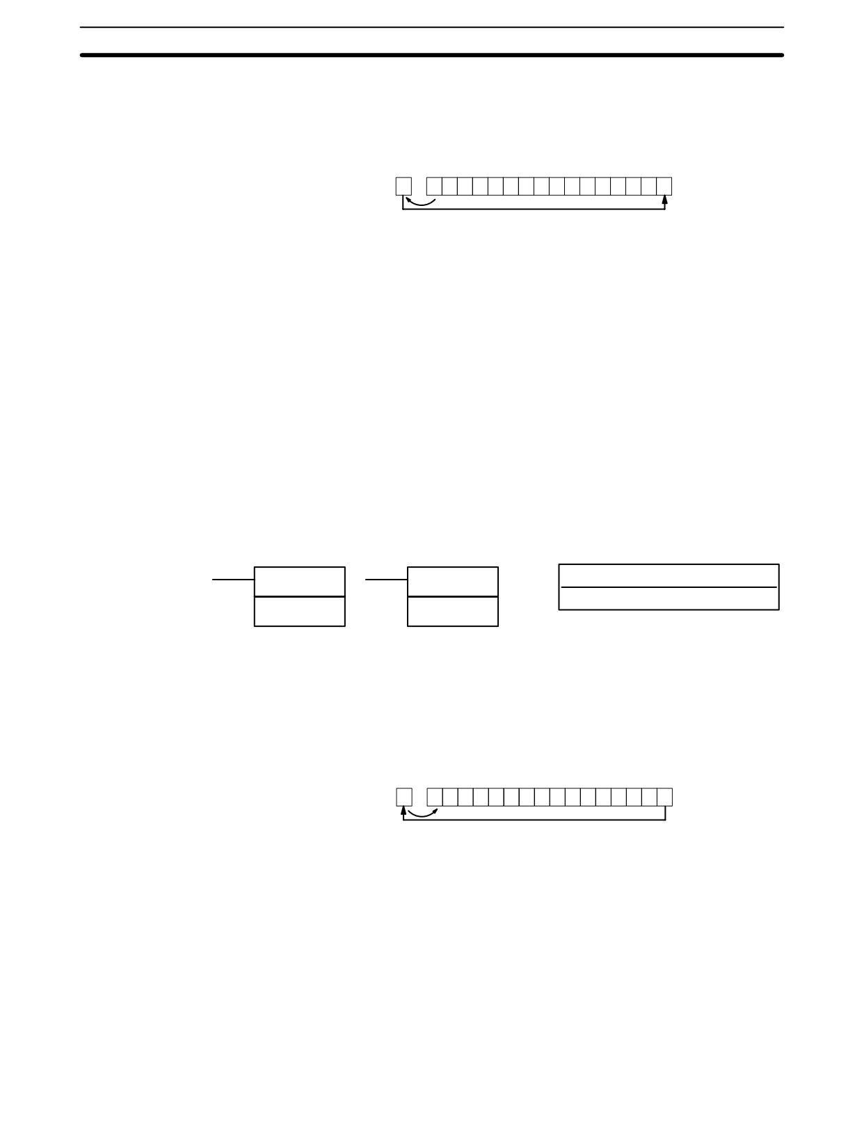
Shift Instructions
Section
7-16
When the execution condition is OFF, ROL(27) is not executed. When the
Description
execution condition is ON, ROL(27) shifts all Wd bits one bit to the left, shifting
CY into bit 00 of Wd and shifting bit 15 of Wd into CY.
Bit
Bit
CY
15
00
0
1
0
1
1
0
0
1
1
1
0
0
0
1
1
0
1
Use STC(41) to set the status of CY or CLC(41) to clear the status of CY before
Precautions
doing a rotate operation to ensure that CY contains the proper status before
executing ROL(27).
CY will be shifted into bit 00 every cycle if the undifferentiated form of ROL(27) is
used. Use the differentiated form (@ROL(27)) or combine ROL(27) with
DIFU(13) or DIFD(14) to shift just one time.
Flags
ER:
Indirectly addressed DM word is non-existent. (Content of *DM word is
not BCD, or the DM area boundary has been exceeded.)
CY:
Receives the data of bit 15.
EQ:
ON when the content of Wd is zero; otherwise OFF.
7-16-6
ROTATE RIGHT - ROR(28)
Ladder Symbols
Operand Data Areas
Wd: Rotate word
ROR(28)
@ROR(28)
IR, SR, AR, DM, HR, LR
Wd
Wd
Limitations
DM 6144 to DM 6655 cannot be used for Wd.
When the execution condition is OFF, ROR(28) is not executed. When the
Description
execution condition is ON, ROR(28) shifts all Wd bits one bit to the right, shifting
CY into bit 15 of Wd and shifting bit 00 of Wd into CY.
Bit
Bit
CY
15
00
0
0
1
0
1
0
1
0
0
0
1
1
1
0
0
0
1
Use STC(41) to set the status of CY or CLC(41) to clear the status of CY before
Precautions
doing a rotate operation to ensure that CY contains the proper status before
execution ROR(28).
CY will be shifted into bit 15 every cycle if the undifferentiated form of ROR(28) is
used. Use the differentiated form (@ROR(28)) or combine ROR(28) with
DIFU(13) or DIFD(14) to shift just one time.
Flags
ER:
Indirectly addressed DM word is non-existent. (Content of *DM word is
not BCD, or the DM area boundary has been exceeded.)
CY:
Receives the data of bit 00.
EQ:
ON when the content of Wd is zero; otherwise OFF.
403
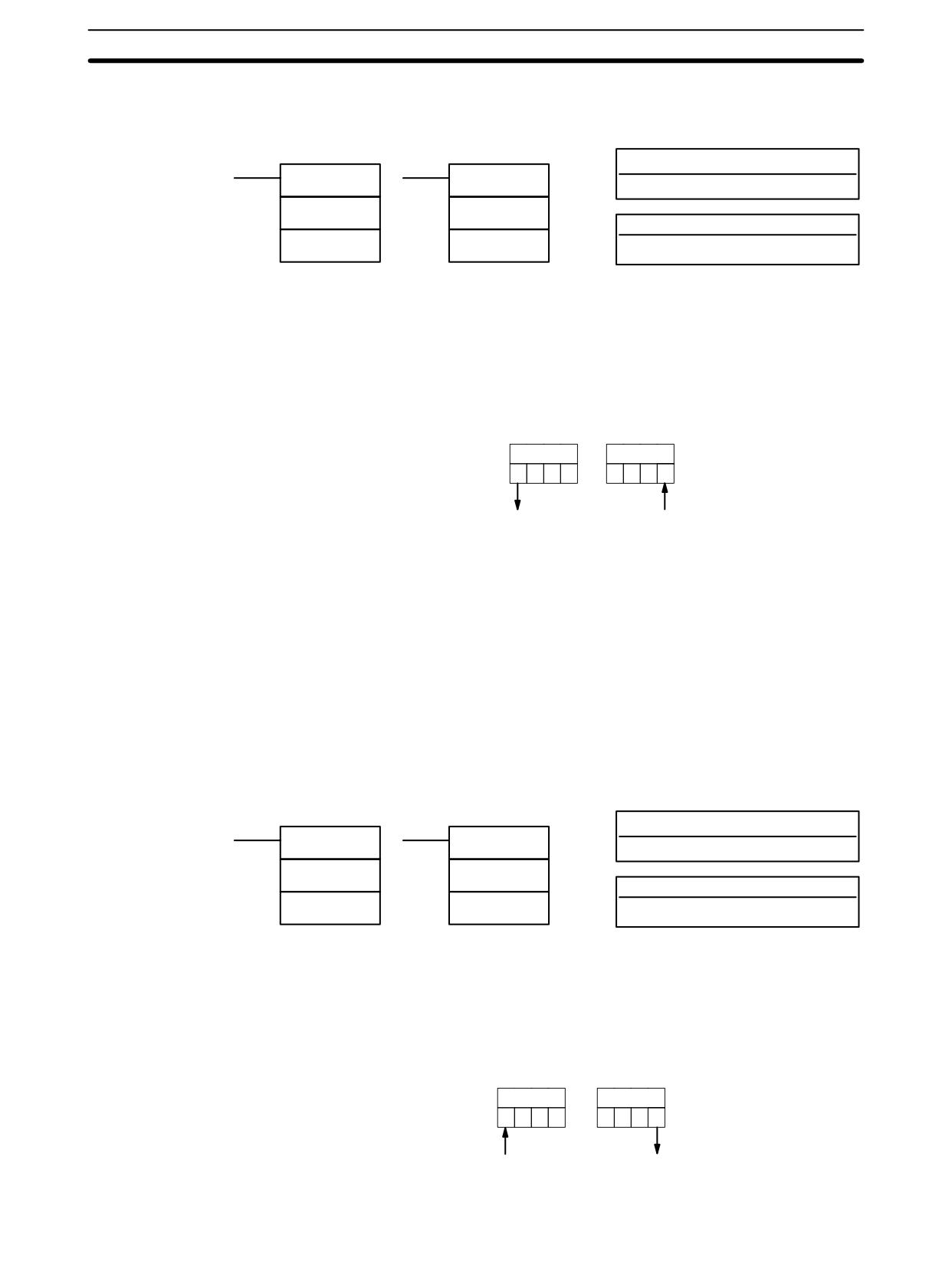
Shift Instructions
Section
7-16
7-16-7
ONE DIGIT SHIFT LEFT - SLD(74)
Ladder Symbols
Operand Data Areas
St: Starting word
SLD(74)
@SLD(74)
IR, SR, AR, DM, HR, LR
St
St
E: End word
E
E
IR, SR, AR, DM, HR, LR
Limitations
St and E must be in the same data area, and E must be greater than or equal to
St.
DM 6144 to DM 6655 cannot be used for St or E.
When the execution condition is OFF, SLD(74) is not executed. When the execu-
Description
tion condition is ON, SLD(74) shifts data between St and E (inclusive) by one
digit (four bits) to the left. 0 is written into the rightmost digit of the St, and the
content of the leftmost digit of E is lost.
E
St
8
F
C
5
D
7
9
1
Lost data
0
Precautions
If a power failure occurs during a shift operation across more than 50 words, the
shift operation might not be completed.
A 0 will be shifted into the least significant digit of St every cycle if the undifferen-
tiated form of SLD(74) is used. Use the differentiated form (@SLD(74)) or com-
bine SLD(74) with DIFU(13) or DIFD(14) to shift just one time.
Flags
ER:
The St and E words are in different areas, or St is greater than E.
Indirectly addressed DM word is non-existent. (Content of *DM word is
not BCD, or the DM area boundary has been exceeded.)
7-16-8
ONE DIGIT SHIFT RIGHT - SRD(75)
Ladder Symbols
Operand Data Areas
E: End word
SRD(75)
@SRD(75)
IR, SR, AR, DM, HR, LR
E
E
St: Starting word
St
St
IR, SR, AR, DM, HR, LR
Limitations
St and E must be in the same data area, and E must be less than or equal to St.
DM 6144 to DM 6655 cannot be used for St or E.
Description
When the execution condition is OFF, SRD(75) is not executed. When the
execution condition is ON, SRD(75) shifts data between St and E (inclusive) by
one digit (four bits) to the right. 0 is written into the leftmost digit of St and the
rightmost digit of E is lost.
St
E
3
4
5
2
F
8
C
1
0
Lost data
404
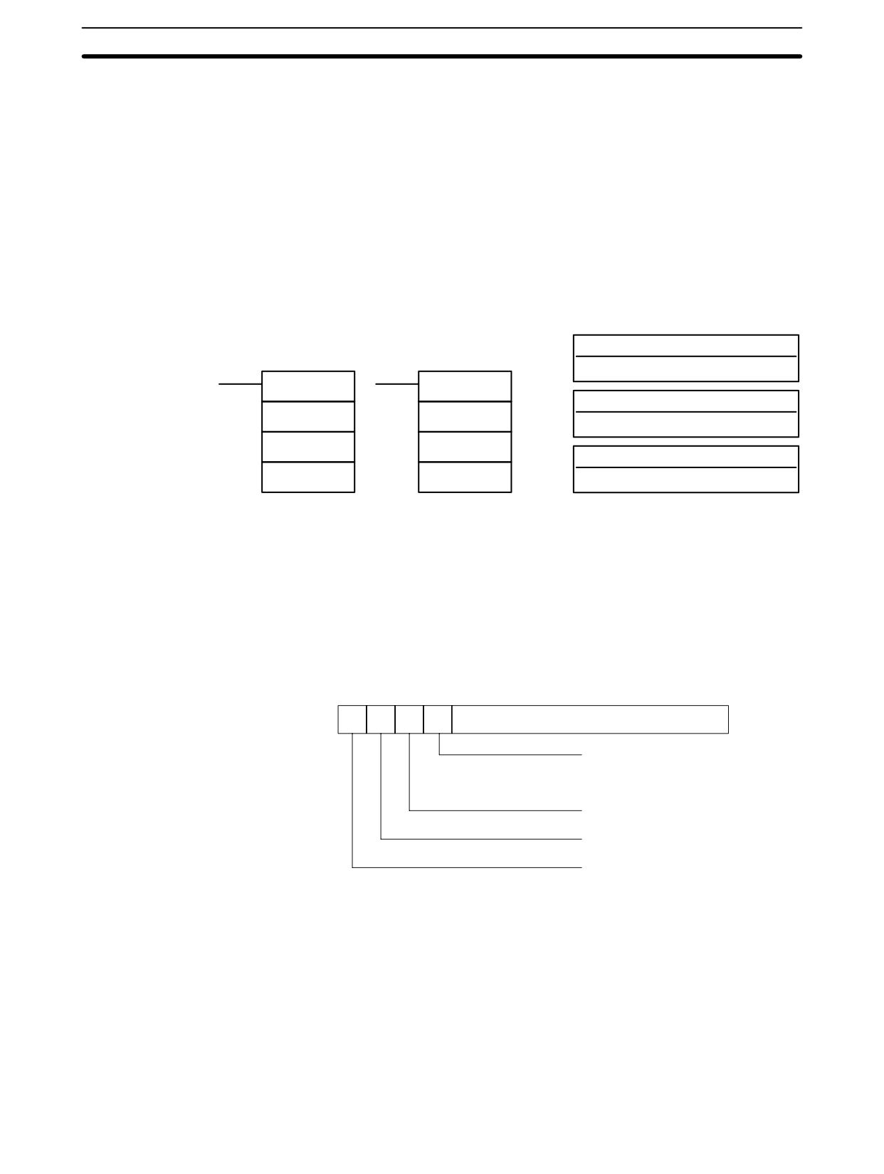
Shift Instructions
Section
7-16
If a power failure occurs during a shift operation across more than 50 words, the
Precautions
shift operation might not be completed.
A 0 will be shifted into the most significant digit of St every cycle if the undifferen-
tiated form of SRD(75) is used. Use the differentiated form (@SRD(75)) or com-
bine SRD(75) with DIFU(13) or DIFD(14) to shift just one time.
Flags
ER:
The St and E words are in different areas, or St is less than E.
Indirectly addressed DM word is non-existent. (Content of *DM word is
not BCD, or the DM area boundary has been exceeded.)
7-16-9
REVERSIBLE SHIFT REGISTER - SFTR(84)
Operand Data Areas
Ladder Symbols
C: Control word
IR, SR, AR, DM, HR, LR
SFTR(84)
@SFTR(84)
St: Starting word
C
C
IR, SR, AR, DM, HR, LR
St
St
E: End word
E
E
IR, SR, AR, DM, HR, LR
St and E must be in the same data area and St must be less than or equal
Limitations
to E.
DM 6144 to DM 6655 cannot be used for C, St, or E.
Description
SFTR(84) is used to create a single- or multiple-word shift register that can shift
data to either the right or the left. To create a single-word register, designate the
same word for St and E. The control word provides the shift direction, the status
to be put into the register, the shift pulse, and the reset input. The control word is
allocated as follows:
15
14
13
12
Not used.
Shift direction
1 (ON): Left (LSB to MSB)
0 (OFF): Right (MSB to LSB)
Status to input into register
Shift pulse bit
Reset
The data in the shift register will be shifted one bit in the direction indicated by bit
12, shifting one bit out to CY and the status of bit 13 into the other end whenever
SFTR(84) is executed with an ON execution condition as long as the reset bit is
OFF and as long as bit 14 is ON. If SFTR(84) is executed with an OFF execution
condition or if SFTR(84) is executed with bit 14 OFF, the shift register will remain
unchanged. If SFTR(84) is executed with an ON execution condition and the re-
set bit (bit 15) is OFF, the entire shift register and CY will be set to zero.
Flags
ER:
St and E are not in the same data area or ST is greater than E.
Indirectly addressed DM word is non-existent. (Content of *DM word is
not BCD, or the DM area boundary has been exceeded.)
405
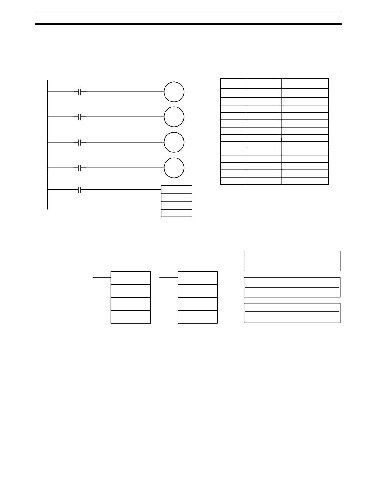
Shift Instructions
Section
7-16
CY:
Receives the status of bit 00 of St or bit 15 of E, depending on the shift
direction.
Example
In the following example, IR 00000, IR 00001, IR 00002, and IR 00003 are used
to control the bits of C used in @SFTR(84). The shift register is in DM 0010, and
it is controlled through IR 00004.
Address
Instruction
Operands
00000
20012
Direction
00000
LD
00000
00001
OUT
20012
00002
LD
00001
00001
20013
Status to input
00003
OUT
20013
00004
LD
00002
00005
OUT
20014
00002
00006
LD
00003
20014
Shift pulse
00007
OUT
20015
00008
LD
00004
00009
@SFTR(84)
00003
20015
Reset
200
DM
0010
00004
DM
0011
@SFTR(84)
200
DM 0010
DM 0011
7-16-10 ASYNCHRONOUS SHIFT REGISTER - ASFT(17)
Operand Data Areas
C: Control word
Ladder Symbols
IR, SR, AR, DM, HR, LR, #
ASFT(17)
@ASFT(17)
St: Starting word
C
C
IR, SR, AR, DM, HR, LR
St
St
E: End word
E
E
IR, SR, AR, DM, HR, LR
Note ASFT(17) is an expansion instruction for the SRM1(-V2). The function code 17 is
the factory setting and can be changed for the SRM1(-V2) if desired.
Limitations
St and E must be in the same data area, and E must be greater than or equal to
St.
DM 6144 to DM 6655 cannot be used for St or E.
Description
When the execution condition is OFF, ASFT(17) does nothing and the program
moves to the next instruction. When the execution condition is ON, ASFT(17) is
used to create and control a reversible asynchronous word shift register be-
tween St and E. This register only shifts words when the next word in the register
is zero, e.g., if no words in the register contain zero, nothing is shifted. Also, only
one word is shifted for each word in the register that contains zero. When the
contents of a word are shifted to the next word, the original word’s contents are
set to zero. In essence, when the register is shifted, each zero word in the regis-
ter trades places with the next word. (See Example below.)
The shift direction (i.e. whether the “next word” is the next higher or the next low-
er word) is designated in C. C is also used to reset the register. All of any portion
of the register can be reset by designating the desired portion with St and E.
406
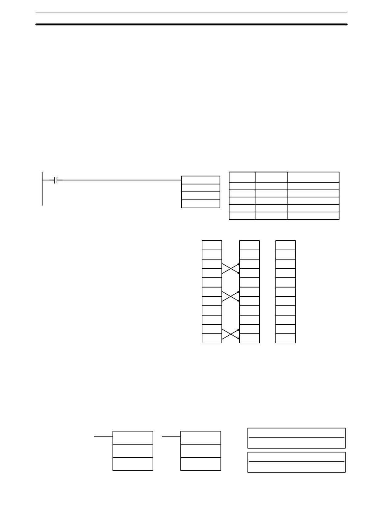
Data Movement Instructions
Section
7-17
Control Word
Bits 00 through 12 of C are not used. Bit 13 is the shift direction: turn bit 13 ON to
shift down (toward lower addressed words) and OFF to shift up (toward higher
addressed words). Bit 14 is the Shift Enable Bit: turn bit 14 ON to enable shift
register operation according to bit 13 and OFF to disable the register. Bit 15 is the
Reset bit: the register will be reset (set to zero) between St and E when
ASFT(17) is executed with bit 15 ON. Turn bit 15 OFF for normal operation.
Note
If the non-differentiated form of ASFT(17) is used, data will be shifted every cycle
while the execution condition is ON. Use the differentiated form to prevent this.
Flags
ER:
The St and E words are in different areas, or St is greater than E.
Indirectly addressed DM word is non-existent. (Content of *DM word is
not BCD, or the DM area boundary has been exceeded.)
Example
The following example shows instruction ASFT(17) used to shift words in an
11-word shift register created between DM 0100 and DM 0110 with C=#6000.
Non-zero data is shifted towards St (DM 0110).
00000
Address
Instruction
Operands
ASFT(17)
00000
LD
00000
#6000
00001
ASFT(17)
DM 0100
#
6000
DM 0110
DM
0100
DM
0110
Before
After one
After seven
execution
execution
executions
DM 0100
1234
1234
1234
DM 0101
0000
0000
2345
DM 0102
0000
2345
3456
DM 0103
2345
0000
4567
DM 0104
3456
3456
5678
DM 0105
0000
4567
6789
DM 0106
4567
0000
789A
DM 0107
5678
5678
0000
DM 0108
6789
6789
0000
DM 0109
0000
789A
0000
DM 0110
789A
0000
0000
Note
The zeroes are shifted “upward” if C=4000, and the entire shift register is set to
zero if C=8000.
7-17 Data Movement Instructions
7-17-1
MOVE - MOV(21)
Ladder Symbols
Operand Data Areas
S: Source word
MOV(21)
@MOV(21)
IR, SR, AR, DM, HR, TC, LR, #
S
S
D: Destination word
D
D
IR, SR, AR, DM, HR, LR
407
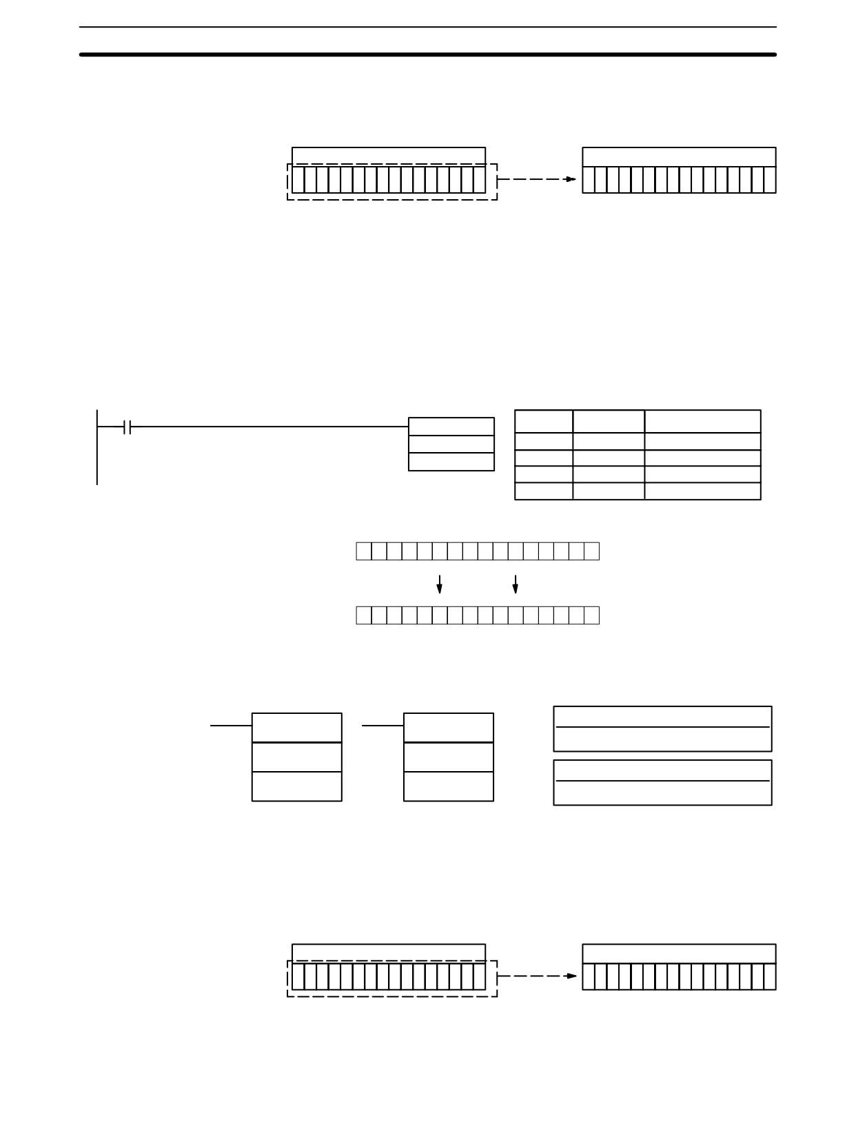
Data Movement Instructions
Section
7-17
Limitations
DM 6144 to DM 6655 cannot be used for D.
Description
When the execution condition is OFF, MOV(21) is not executed. When the
execution condition is ON, MOV(21) copies the content of S to D.
Source word
Destination word
Bit status
not changed.
TC numbers cannot be designated as D to change the PV of the timer or counter.
Precautions
You can, however, easily change the PV of a timer or a counter by using
BSET(71).
Flags
ER:
Indirectly addressed DM word is non-existent. (Content of *DM word is
not BCD, or the DM area boundary has been exceeded.)
EQ:
ON when all zeros are transferred to D.
Example
The following example shows @MOV(21) being used to copy the content of
IR 001 to HR 05 when IR 00000 goes from OFF to ON.
00000
Address
Instruction
Operands
@MOV(21)
001
00000
LD
00000
HR 05
00001
@MOV(21)
001
HR
05
IR 000
0
1
1
1
0
0
1
1
1
0
0
0
0
1
0
1
HR 05
0
1
1
1
0
0
1
1
1
0
0
0
0
1
0
1
7-17-2
MOVE NOT - MVN(22)
Ladder Symbols
Operand Data Areas
S: Source word
MVN(22)
@MVN(22)
IR, SR, AR, DM, HR, TC, LR, #
S
S
D: Destination word
D
D
IR, SR, AR, DM, HR, LR
Limitations
DM 6144 to DM 6655 cannot be used for D.
Description
When the execution condition is OFF, MVN(22) is not executed. When the
execution condition is ON, MVN(22) transfers the inverted content of S (speci-
fied word or four-digit hexadecimal constant) to D, i.e., for each ON bit in S, the
corresponding bit in D is turned OFF, and for each OFF bit in S, the correspond-
ing bit in D is turned ON.
Source word
Destination word
Bit status
inverted.
TC numbers cannot be designated as D to change the PV of the timer or counter.
Precautions
However, these can be easily changed using BSET(71).
408
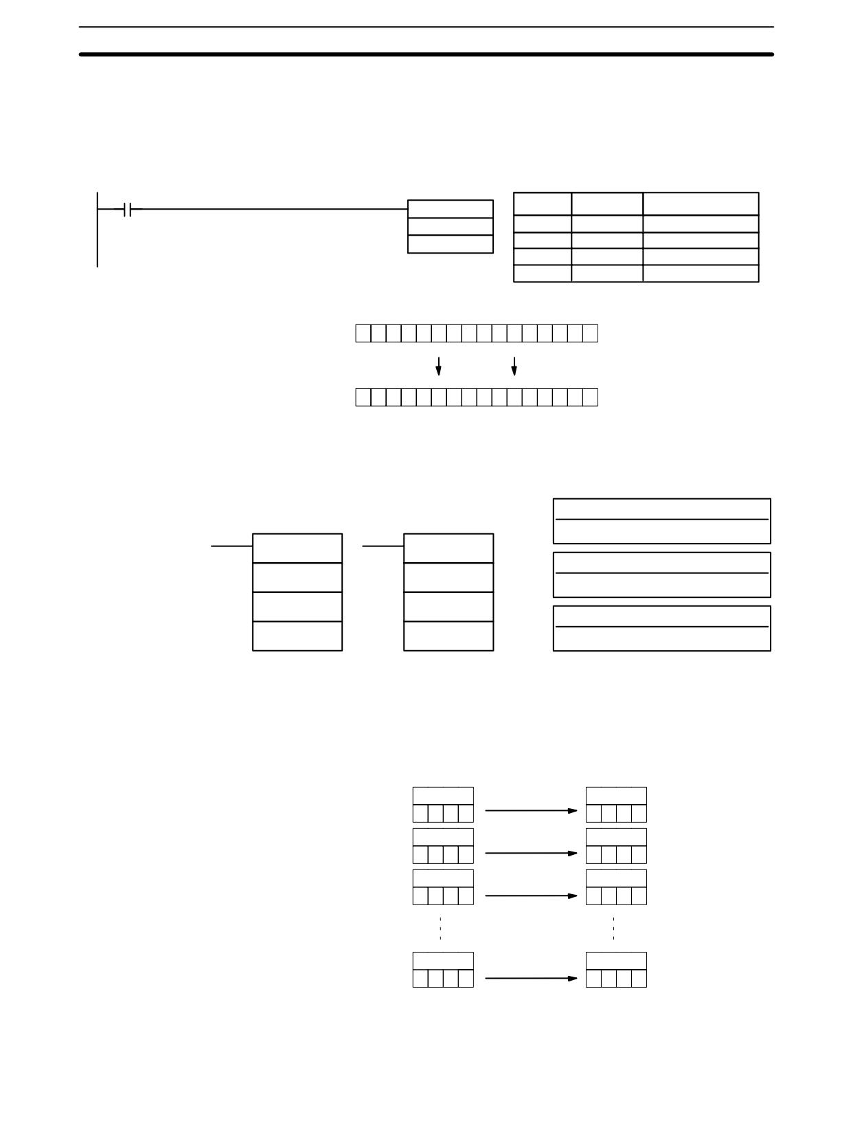
Data Movement Instructions
Section
7-17
Flags
ER:
Indirectly addressed DM word is non-existent. (Content of *DM word is
not BCD, or the DM area boundary has been exceeded.)
EQ:
ON when all zeros are transferred to D.
Example
The following example shows @MVN(22) being used to copy the complement of
#F8C5 to DM 0010 when IR 00001 goes from OFF to ON.
00001
Address
Instruction
Operands
@MVN(22)
#F8C5
00000
LD
00001
DM 0010
00001
@MOV(21)
#
F8C5
DM
0010
#F8C5
1
1
1
1
1
0
0
0
1
1
0
0
0
1
0
1
DM 0010
0
0
0
0
0
1
1
1
0
0
1
1
1
0
1
0
7-17-3
BLOCK TRANSFER - XFER(70)
Operand Data Areas
Ladder Symbols
N: Number of words (BCD)
IR, SR, AR, DM, HR, TC, LR, #
XFER(70)
@XFER(70)
S: Starting source word
N
N
IR, SR, AR, DM, HR, TC, LR
S
S
D: Starting destination word
D
D
IR, SR, AR, DM, HR, TC, LR
Limitations
S and S+N must be in the same data area, as must D and D+N.
DM 6144 to DM 6655 cannot be used for D.
Description
When the execution condition is OFF, XFER(70) is not executed. When the
execution condition is ON, XFER(70) copies the contents of S, S+1, ..., S+N to
D, D+1, ..., D+N.
S
D
3
4
5
2
3
4
5
2
S+1
D+1
3
4
5
1
3
4
5
1
S+2
D+2
3
4
2
2
3
4
2
2
S+N
D+N
6
4
5
2
6
4
5
2
Flags
ER:
N is not BCD
S and S+N or D and D+N are not in the same data area.
409
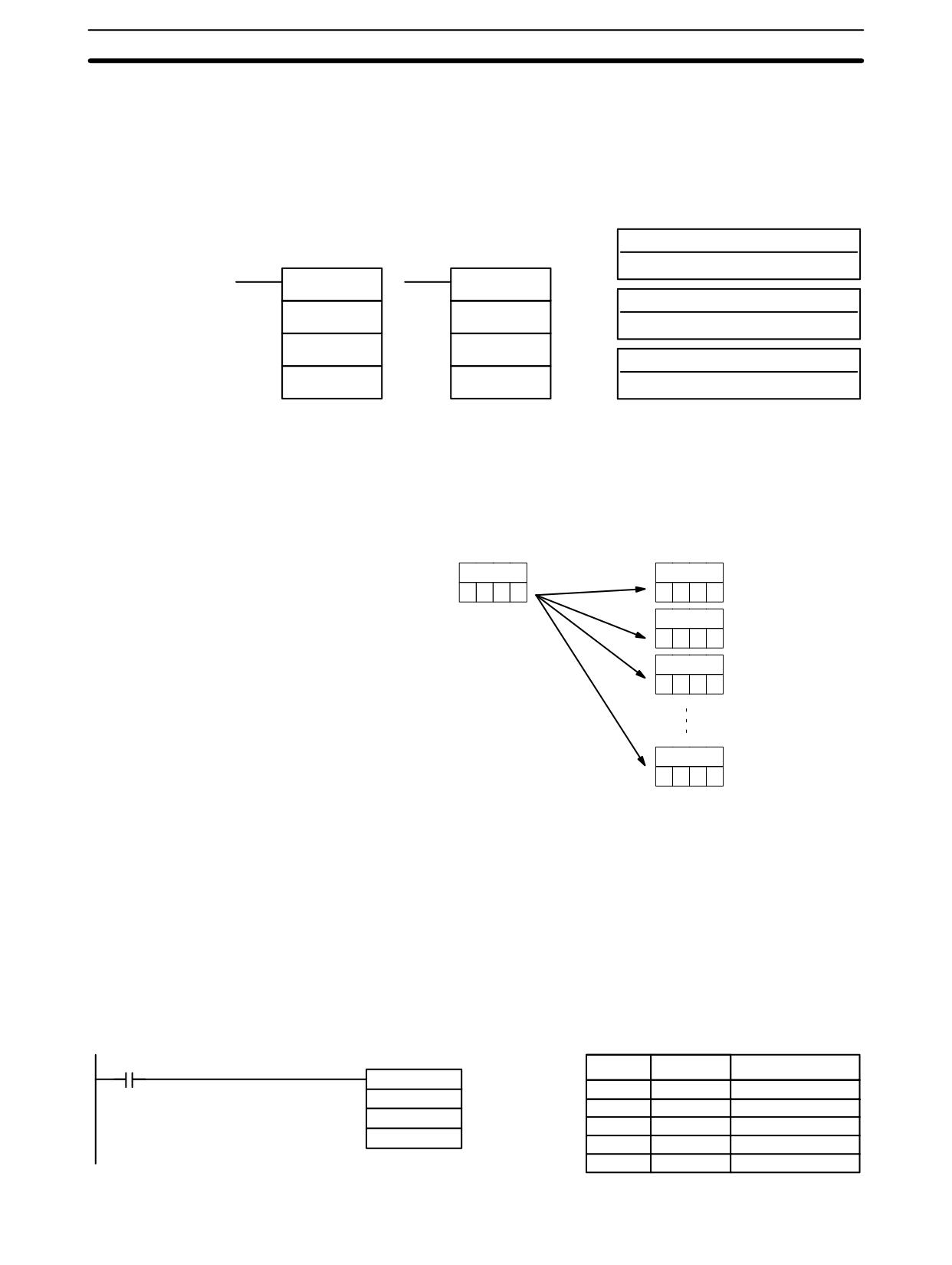
Data Movement Instructions
Section
7-17
Indirectly addressed DM word is non-existent. (Content of *DM word is
not BCD, or the DM area boundary has been exceeded.)
7-17-4
BLOCK SET - BSET(71)
Operand Data Areas
Ladder Symbols
S: Source data
IR, SR, AR, DM, HR, TC, LR, #
BSET(71)
@BSET(71)
St: Starting word
S
S
IR, SR AR, DM, HR, TC, LR
St
St
E: End Word
E
E
IR, SR, AR, DM, HR, TC, LR
Limitations
St must be less than or equal to E, and St and E must be in the same data area.
DM 6144 to DM 6655 cannot be used for St or E.
Description
When the execution condition is OFF, BSET(71) is not executed. When the
execution condition is ON, BSET(71) copies the content of S to all words from St
through E.
S
St
3
4
5
2
3
4
5
2
St+1
3
4
5
2
St+2
3
4
5
2
E
3
4
5
2
BSET(71) can be used to change timer/counter PV. (This cannot be done with
MOV(21) or MVN(22).) BSET(71) can also be used to clear sections of a data
area, i.e., the DM area, to prepare for executing other instructions. It can also be
used to clear words by transferring all zeros.
Flags
ER:
St and E are not in the same data area or St is greater than E.
Indirectly addressed DM word is non-existent. (Content of *DM word is
not BCD, or the DM area boundary has been exceeded.)
The following example shows how to use BSET(71) to copy a constant (#0000)
Example
to a block of the DM area (DM 0000 to DM 0500) when IR 00000 is ON.
00000
Address
Instruction
Operands
@BSET(71)
00000
LD
00000
#0000
00001
@BSET(71)
DM 0000
#
0000
DM 0500
DM
0000
DM
0500
410
Data Movement Instructions
Section
7-17
7-17-5
DATA EXCHANGE - XCHG(73)
Ladder Symbols
Operand Data Areas
E1: Exchange word 1
XCHG(73)
@XCHG(73)
IR, SR, AR, DM, HR, TC, LR
E1
E1
E2: Exchange word 2
E2
E2
IR, SR, AR, DM, HR, TC, LR
Limitations
DM 6144 to DM 6655 cannot be used for E1 or E2.
Description
When the execution condition is OFF, XCHG(73) is not executed. When the
execution condition is ON, XCHG(73) exchanges the content of E1 and E2.
E1
E2
If you want to exchange content of blocks whose size is greater than 1 word, use
work words as an intermediate buffer to hold one of the blocks using XFER(70)
three times.
Flags
ER:
Indirectly addressed DM word is non-existent. (Content of *DM word is
not BCD, or the DM area boundary has been exceeded.)
7-17-6
SINGLE WORD DISTRIBUTE - DIST(80)
Operand Data Areas
Ladder Symbols
S: Source data
IR, SR, AR, DM, HR, TC, LR, #
DIST(80)
@DIST(80)
DBs: Destination base word
S
S
IR, SR, AR, DM, HR, TC, LR
DBs
DBs
C: Control word (BCD)
C
C
IR, SR, AR, DM, HR, TC, LR, #
Limitations
C must be BCD.
DM 6144 to DM 6655 cannot be used for DBs or C.
Description
DIST(80) can be used for single-word distribution or for a stack operation de-
pending on the content of the control word, C.
When bits 12 to 15 of C=0 to 8, DIST(80) can be used for a single word distribute
Single-word Distribution
operation. The entire contents of C specifies an offset, Of (0000 to 2047 in BCD).
When the execution condition is OFF, DIST(80) is not executed. When the
execution condition is ON, DIST(80) copies the content of S to DBs+Of, i.e., Of is
added to DBs to determine the destination word.
Note DBs and DBs+Of must be in the same data area and cannot be between
DM 6144 and DM 6655.
Example
The following example shows how to use DIST(80) to copy #00FF to HR 10 + Of.
411
Data Movement Instructions
Section
7-17
The content of LR 10 is #3005, so #00FF is copied to HR 15 (HR 10 + 5) when
IR 00000 is ON.
00000
Address
Instruction
Operands
@DIST(80)
00000
LD
00000
#00FF
00001
@DIST(80)
HR 10
#
00FF
LR 10
HR
10
LR
10
LR 10
#00FF
HR 10
3
0
0
5
0
0
F
F
0
0
0
0
HR 15
0
0
F
F
Stack Operation
When bits 12 to 15 of C=9, DIST(80) can be used for a stack operation. The other
3 digits of C specify the number of words in the stack (000 to 999 in BCD). The
content of DBs is the stack pointer.
When the execution condition is OFF, DIST(80) is not executed. When the
execution condition is ON, DIST(80) copies the content of S to DBs+1+the con-
tent of DBs. In other words, 1 and the content of DBs are added to DBs to deter-
mine the destination word. The content of DBs is then incremented by 1.
Note
1. DIST(80) will be executed every cycle unless the differentiated form
(@DIST(80)) is used or DIST(80) is used with DIFU(13) or DIFD(14).
2. Be sure to initialize the stack pointer before using DIST(80) as a stack op-
eration.
Example
The following example shows how to use DIST(80) to create a stack between
DM 0001 and DM 0005. DM 0000 acts as the stack pointer.
00000
Address
Instruction
Operands
@DIST(80)
00000
LD
00000
200
00001
@DIST(80)
DM 0000
200
216
DM
0000
216
IR 200
FFFF
IR 216
9005
DM 0000
0000
DM 0000
0001
DM 0000
0002
First execution
Second
DM 0001
0000
DM 0001
FFFF
execution
DM 0001
FFFF
DM 0002
0000
DM 0002
0000
DM 0002
FFFF
DM 0003
0000
Stack pointer
DM 0003
0000
DM 0003
0000
Stack pointer
DM 0004
0000
incremented
DM 0004
0000
DM 0004
0000
incremented
DM 0005
0000
DM 0005
0000
DM 0005
0000
Flags
ER:
The offset or stack length in the control word is not BCD.
Indirectly addressed DM word is non-existent. (Content of *DM word is
not BCD, or the DM area boundary has been exceeded.)
412
Data Movement Instructions
Section
7-17
During stack operation, the value of the stack pointer+1 exceeds the
length of the stack.
EQ:
ON when the content of S is zero; otherwise OFF.
7-17-7
DATA COLLECT - COLL(81)
Operand Data Areas
Ladder Symbols
SBs: Source base word
IR, SR, AR, DM, HR, TC, LR
COLL(81)
@COLL(81)
C: Control word (BCD)
SBs
SBs
IR, SR, AR, DM, HR, TC, LR, #
C
C
D: Destination word
D
D
IR, SR, AR, DM, HR, TC, LR
C must be BCD.
Limitations
DM 6144 to DM 6655 cannot be used for D.
Description
COLL(81) can be used for data collection, an FIFO stack operation, or an LIFO
stack operation depending on the content of the control word, C.
Data Collection
When bits 12 to 15 of C=0 to 7, COLL(81) is used for data collection. The entire
contents of C specifies an offset, Of (0000 to 2047 in BCD).
When the execution condition is OFF, COLL(81) is not executed. When the
execution condition is ON, COLL(81) copies the content of SBs + Of to D, i.e., Of
is added to SBs to determine the source word.
Note SBs and SBs+Of must be in the same data area.
Example
The following example shows how to use COLL(81) to copy the content of
DM 0000+Of to LR 00. The content of 200 is #0005, so the content of DM 0005
(DM 0000 + 5) is copied to LR 00 when IR 00001 is ON.
00001
Address
Instruction
Operands
@COLL(81)
00000
LD
00001
DM 0000
00001
@DIST(80)
200
DM
0000
LR 00
200
LR
00
200
DM 0000
LR 00
0
0
0
5
0
0
0
0
0
0
F
F
DM 0005
0
0
F
F
FIFO Stack Operation
When bits 12 to 15 of C=9, COLL(81) can be used for an FIFO stack operation.
The other 3 digits of C specify the number of words in the stack (000 to 999, in
BCD). The content of SBs is the stack pointer.
When the execution condition is ON, COLL(81) shifts the contents of each word
within the stack down by one address, finally shifting the data from SBs+1 (the
first value written to the stack) to the destination word (D). The content of the
stack pointer (SBs) is then decremented by one.
413
Data Movement Instructions
Section
7-17
Note
COLL(81) will be executed every cycle unless the differentiated form
(@COLL(81)) is used or COLL(81) is used with DIFU(13) or DIFD(14).
Example
The following example shows how to use COLL(81) to create a stack between
DM 0001 and DM 0005. DM 0000 acts as the stack pointer.
When IR 00000 goes from OFF to ON, COLL(81) shifts the contents of DM 0002
to DM 0005 down by one address, and shifts the data from DM 0001 to IR 001.
The content of the stack pointer (DM 0000) is then decremented by one.
00000
Address
Instruction
Operands
@COLL(81)
00000
LD
00000
DM 0000
00001
@COLL(81)
216
DM
0000
001
216
001
IR 216
9005
Stack pointer
DM 0000
0005
decremented
DM 0000
0004
IR 001
AAAA
DM 0001
AAAA
DM 0001
BBBB
DM 0002
BBBB
DM 0002
CCCC
DM 0003
CCCC
DM 0003
DDDD
DM 0004
DDDD
DM 0004
EEEE
DM 0005
EEEE
DM 0005
EEEE
LIFO Stack Operation
When bits 12 to 15 of C=8, COLL(81) can be used for an LIFO stack operation.
The other 3 digits of C specify the number of words in the stack (000 to 999). The
content of SBs is the stack pointer.
When the execution condition is ON, COLL(81) copies the data from the word
indicated by the stack pointer (SBs+the content of SBs) to the destination word
(D). The content of the stack pointer (SBs) is then decremented by one.
The stack pointer is the only word changed in the stack.
Note
COLL(81) will be executed every cycle unless the differentiated form
(@DIST(80)) is used or DIST(80) is used with DIFU(13) or DIFD(14).
Example
The following example shows how to use COLL(81) to create a stack between
DM 0001 and DM 0005. DM 0000 acts as the stack pointer.
When IR 00000 goes from OFF to ON, COLL(81) copies the content of DM 0005
(DM 0000 + 5) to IR 001. The content of the stack pointer (DM 0000) is then de-
cremented by one.
00000
Address
Instruction
Operands
@COLL(81)
00000
LD
00000
DM 0000
00001
@COLL(81)
216
DM
0000
001
216
001
IR 216
8005
Stack pointer
DM 0000
0005
decremented
DM 0000
0004
IR 001
EEEE
DM 0001
AAAA
DM 0001
AAAA
DM 0002
BBBB
DM 0002
BBBB
DM 0003
CCCC
DM 0003
CCCC
DM 0004
DDDD
DM 0004
DDDD
DM 0005
EEEE
DM 0005
EEEE
414
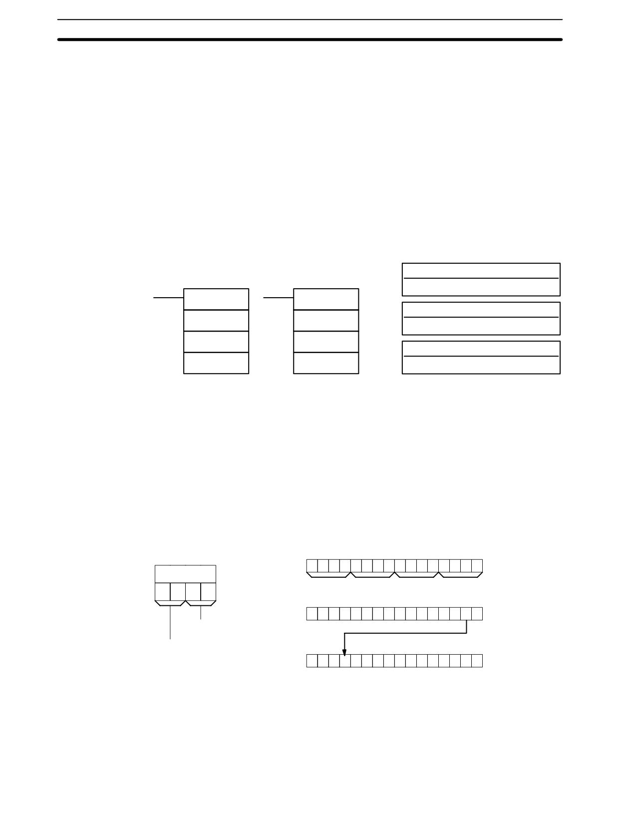
Data Movement Instructions
Section
7-17
Flags
ER:
The offset or stack length in the control word is not BCD.
Indirectly addressed DM word is non-existent. (Content of *DM word is
not BCD, or the DM area boundary has been exceeded.)
During stack operation, the value of the stack pointer exceeds the
length of the stack; an attempt was made to write to a word beyond the
end of the stack.
EQ:
ON when the content of S is zero; otherwise OFF.
7-17-8
MOVE BIT - MOVB(82)
Operand Data Areas
Ladder Symbols
S: Source word
IR, SR, AR, DM, HR, LR, #
MOVB(82)
@MOVB(82)
Bi: Bit designator (BCD)
S
S
IR, SR, AR, DM, HR, TC, LR, #
Bi
Bi
D: Destination word
D
D
IR, SR, AR, DM, HR, LR
Limitations
The rightmost two digits and the leftmost two digits of Bi must each be between
00 and 15.
DM 6144 to DM 6655 cannot be used for Bi or D.
When the execution condition is OFF, MOVB(82) is not executed. When the
Description
execution condition is ON, MOVB(82) copies the specified bit of S to the speci-
fied bit in D. The bits in S and D are specified by Bi. The rightmost two digits of Bi
designate the source bit; the leftmost two bits designate the destination bit.
Bit
Bit
15
00
Bi
0
0
0
1
0
0
1
0
0
0
0
0
0
0
0
1
Bi
1
2
0
1
Bit
1
2
0
1
Bit
MSB
LSB
15
00
S
0
1
0
1
0
1
0
0
0
1
1
1
0
0
0
1
Source bit (00 to 15)
Bit
Bit
Destination bit (00 to 15)
15
00
D
0
1
0
0
0
1
0
0
0
1
1
1
0
0
0
1
Flags
ER:
Bi is not BCD, or it is specifying a non-existent bit (i.e., bit specification
must be between 00 and 15).
Indirectly addressed DM word is non-existent. (Content of *DM word is
not BCD, or the DM area boundary has been exceeded.)
415
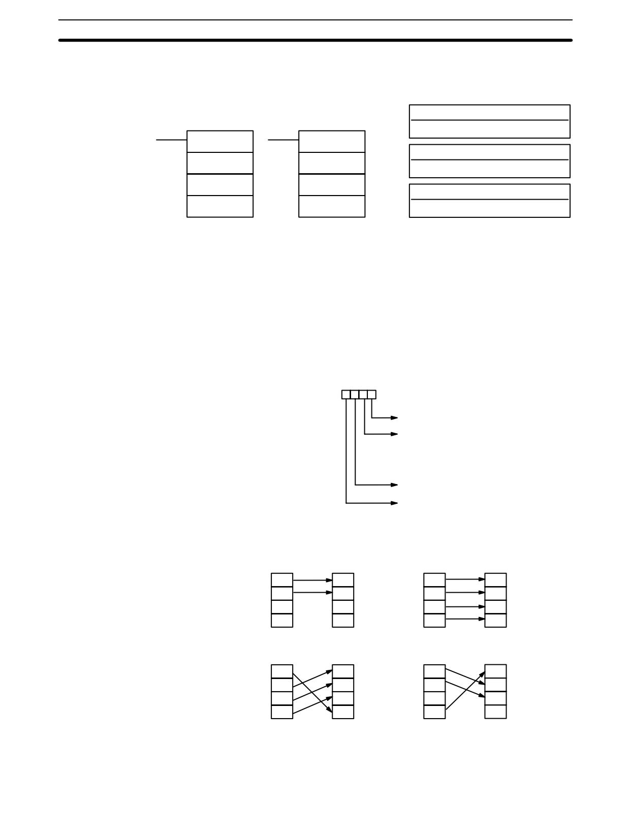
Data Movement Instructions
Section
7-17
7-17-9
MOVE DIGIT - MOVD(83)
Operand Data Areas
Ladder Symbols
S: Source word
IR, SR, AR, DM, HR, TC, LR, #
MOVD(83)
@MOVD(83)
Di: Digit designator (BCD)
S
S
IR, SR, AR, DM, HR, TC, LR, #
Di
Di
D: Destination word
D
D
IR, SR, AR, DM, HR, TC, LR
Limitations
The rightmost three digits of Di must each be between 0 and 3.
DM 6144 to DM 6655 cannot be used for Di or D.
Description
When the execution condition is OFF, MOVD(83) is not executed. When the
execution condition is ON, MOVD(83) copies the content of the specified digit(s)
in S to the specified digit(s) in D. Up to four digits can be transferred at one time.
The first digit to be copied, the number of digits to be copied, and the first digit to
receive the copy are designated in Di as shown below. Digits from S will be co-
pied to consecutive digits in D starting from the designated first digit and contin-
ued for the designated number of digits. If the last digit is reached in either S or D,
further digits are used starting back at digit 0.
Digit number:
3210
First digit in S (0 to 3)
Number of digits (0 to 3)
0: 1 digit
1: 2 digits
2: 3 digits
3: 4 digits
First digit in D (0 to 3)
Not used. (Set to 0.)
Digit Designator
The following show examples of the data movements for various values of Di.
Di: 0010
Di: 0030
S
D
S
D
0
0
0
0
1
1
1
1
2
2
2
2
3
3
3
3
Di: 0031
Di: 0023
S
D
S
D
0
0
0
0
1
1
1
1
2
2
2
2
3
3
3
3
Flags
ER:
At least one of the rightmost three digits of Di is not between 0 and 3.
Indirectly addressed DM word is non-existent. (Content of *DM word is
not BCD, or the DM area boundary has been exceeded.)
416
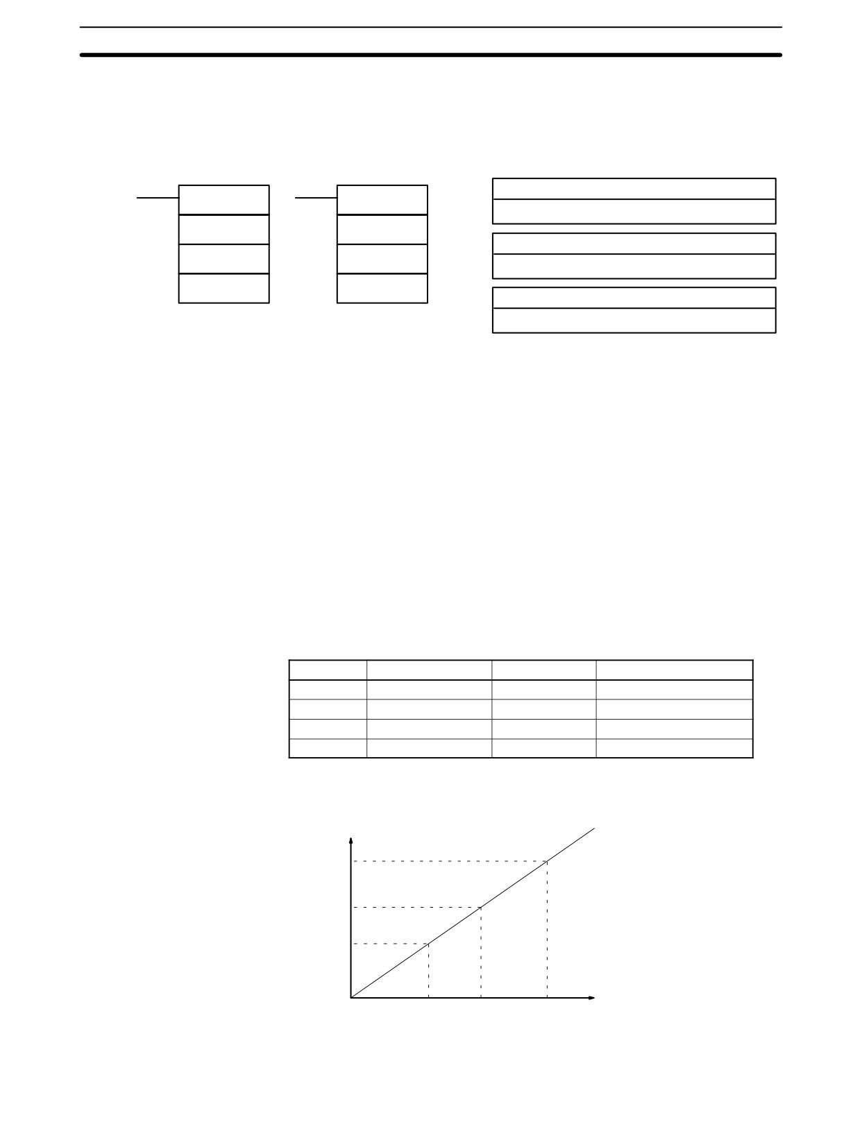
Data Control Instructions
Section
7-18
7-18 Data Control Instructions
7-18-1
SCALING - SCL(66)
Ladder Symbols
Operand Data Areas
S: Source word
SCL(66)
@SCL(66)
IR, SR, AR, DM, HR, TC, LR, #
S
S
P1: First parameter word
P1
P1
IR, SR, AR, DM, HR, TC, LR
R
R
R: Result word
IR, SR, AR, DM, HR, LR
Limitations
This instruction is available in the CPM2A/CPM2C/SRM1(-V2) only.
S must be BCD.
P1 through P1+3 must be in the same data area.
DM 6144 to DM 6655 cannot be used for P1 through P1+3 or R.
Description
SCL(66) is used to linearly convert a 4-digit hexadecimal value to a 4-digit BCD
value. Unlike BCD(24), which converts a 4-digit hexadecimal value to its 4-digit
BCD equivalent (Shex → SBCD), SCL(66) can convert the hexadecimal value ac-
cording to a specified linear relationship. The conversion line is defined by two
points specified in the parameter words P1 to P1+3.
When the execution condition is OFF, SCL(66) is not executed. When the execu-
tion condition is ON, SCL(66) converts the 4-digit hexadecimal value in S to the
4-digit BCD value on the line defined by points (P1, P1+1) and (P1+2, P1+3) and
places the results in R. The results is rounded off to the nearest integer. If the
results is less than 0000, then 0000 is written to R, and if the result is greater than
9999, then 9999 is written to R.
The following table shows the functions and ranges of the parameter words:
Parameter
Function
Range
Comments
P1
BCD point #1 (AY)
0000 to 9999
---
P1+1
Hex. point #1 (AX)
0000 to FFFF
Do not set P1+1=P1+3.
P1+2
BCD point #2 (BY)
0000 to 9999
---
P1+3
Hex. point #2 (BX)
0000 to FFFF
Do not set P1+3=P1+1.
The following diagram shows the source word, S, converted to D according to
the line defined by points (AY, AX) and (BY, BX).
Value after conversion
(BCD)
BY
R
AY
Value before conversion
(Hexadecimal)
AX
S
BX
The results can be calculated by first converting all values to BCD and then using
the following formula.
417
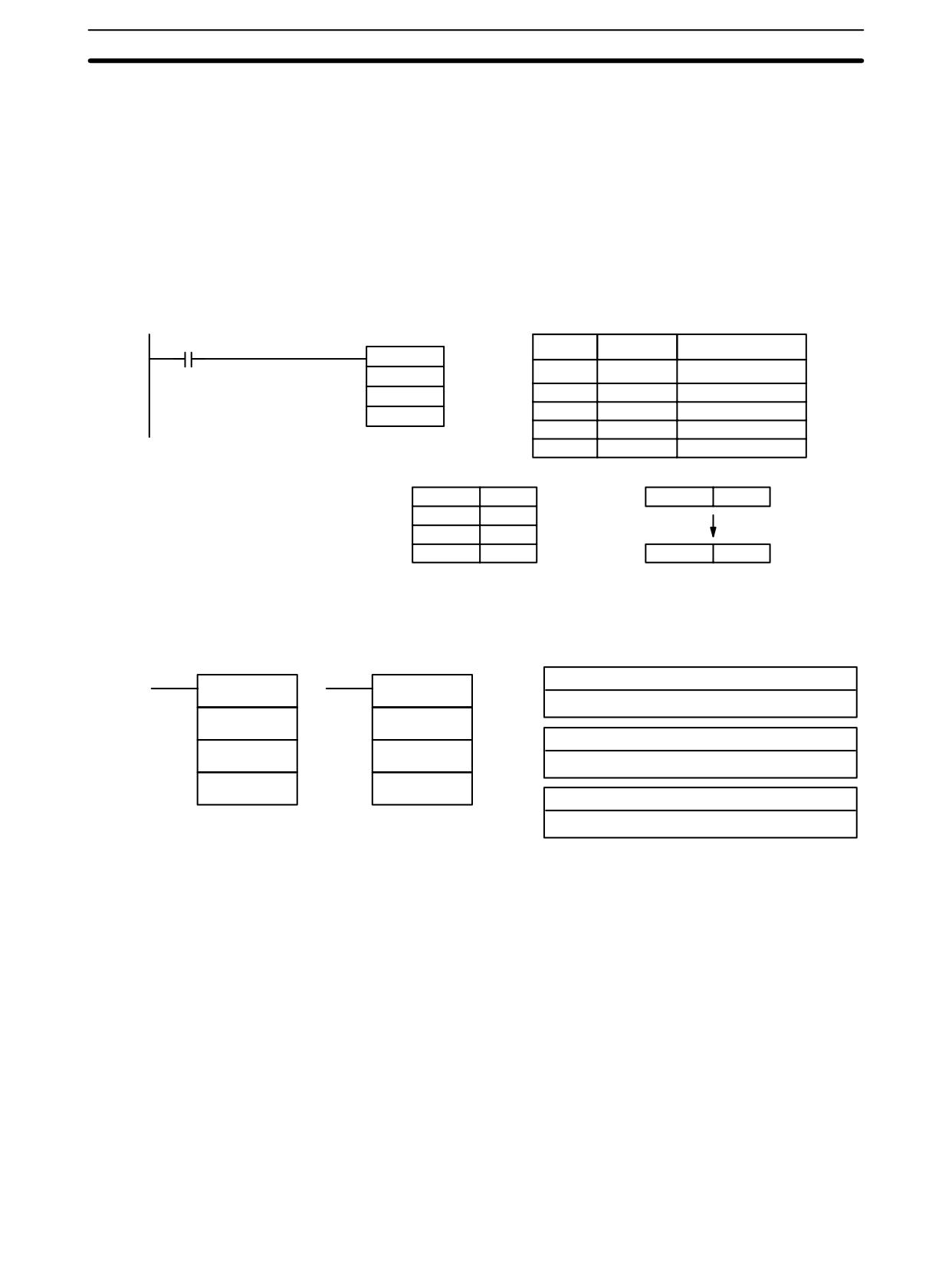
Data Control Instructions
Section
7-18
Results = BY - [(BY - AY)/(BX - AX) × (BX - S)]
Flags
ER:
The value in P1+1 equals that in P1+3.
Indirectly addressed DM word is non-existent. (Content of *DM word is
not BCD, or the DM area boundary has been exceeded.)
P1 and P1+3 are not in the same data area, or other setting error.
EQ:
ON when the result, R, is 0000.
Example
When 00000 is turned ON in the following example, the BCD source data in
DM 0100 (#0100) is converted to hexadecimal according to the parameters in
DM 0150 to DM 0153. The result (#0512) is then written to DM 0200.
00000
Address
Instruction
Operands
@SCL(66)
DM 0100
00000
LD
00000
DM 0150
00001
@SCL(66)
DM
0100
DM 0200
DM
0150
DM
0200
DM 0150
0010
DM 0100
0100
DM 0151
0005
DM 0152
0050
DM 0153
0019
DM 0200
0512
7-18-2
SIGNED BINARY TO BCD SCALING - SCL2(--)
Ladder Symbols
Operand Data Areas
S: Source word
SCL2(--)
@SCL2(--)
IR, SR, AR, DM, HR, LR
S
S
P1: First parameter word
P1
P1
IR, SR, AR, DM, HR, LR
R
R
R: Result word
IR, SR, AR, DM, HR, LR
Limitations
This instruction is available in the CPM2A/CPM2C only.
S must be BCD.
P1 through P1+2 must be in the same data area.
DM 6144 to DM 6655 cannot be used for R.
Description
SCL2(--) is used to linearly convert a 4-digit signed hexadecimal value to a
4-digit BCD value. Unlike BCD(24), which converts a 4-digit hexadecimal value
to its 4-digit BCD equivalent (Shex → SBCD), SCL2(--) can convert the signed
hexadecimal value according to a specified linear relationship. The conversion
line is defined by the x-intercept and the slope of the line specified in the parame-
ter words P1 to P1+2.
When the execution condition is OFF, SCL2(--) is not executed. When the
execution condition is ON, SCL2(--) converts the 4-digit signed hexadecimal
value in S to the 4-digit BCD value on the line defined by the x-intercept (P1, 0)
and the slope (P1+2 ÷ P1+1) and places the results in R. The result is rounded off
to the nearest integer.
418
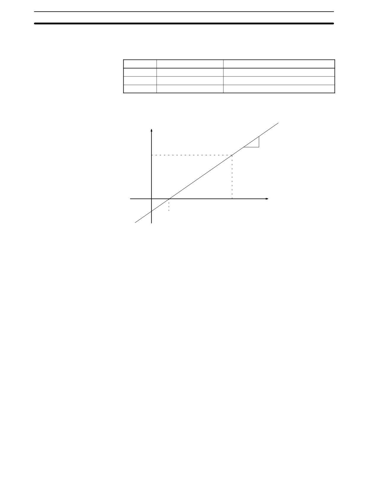
Data Control Instructions
Section
7-18
If the result is negative, then CY is set to 1. If the result is less than -9999, then
-9999 is written to R. If the result is greater than 9999, then 9999 is written to R.
The following table shows the functions and ranges of the parameter words:
Parameter
Function
Range
P1
x-intercept (signed hex.)
8000 to 7FFF (-32,768 to 32,767)
P1+1
∆X (signed hex.)
8000 to 7FFF (-32,768 to 32,767)
P1+2
∆Y (BCD)
0000 to 9999
The following diagram shows the source word, S, converted to R according to
the line defined by the point (P1, 0) and slope ∆Y/∆X.
Value after conversion
(BCD)
∆Y
∆X
R
Value before conversion
(Signed hexadecimal)
S
X-intercept
The result can be calculated by first converting all signed hexadecimal values to
BCD and then using the following formula.
R+DY
(S-P1)
DX
Flags
ER:
Indirectly addressed DM word is non-existent. (Content of *DM word is
not BCD, or the DM area boundary has been exceeded.)
P1 and P1+2 are not in the same data area, or other setting error.
CY:
ON when the result, R, is negative.
EQ:
ON when the result, R, is 0000.
Example
When 05000 is turned ON in the following example, the signed binary source
data in 200 (#FFE2) is converted to BCD according to the parameters in
419
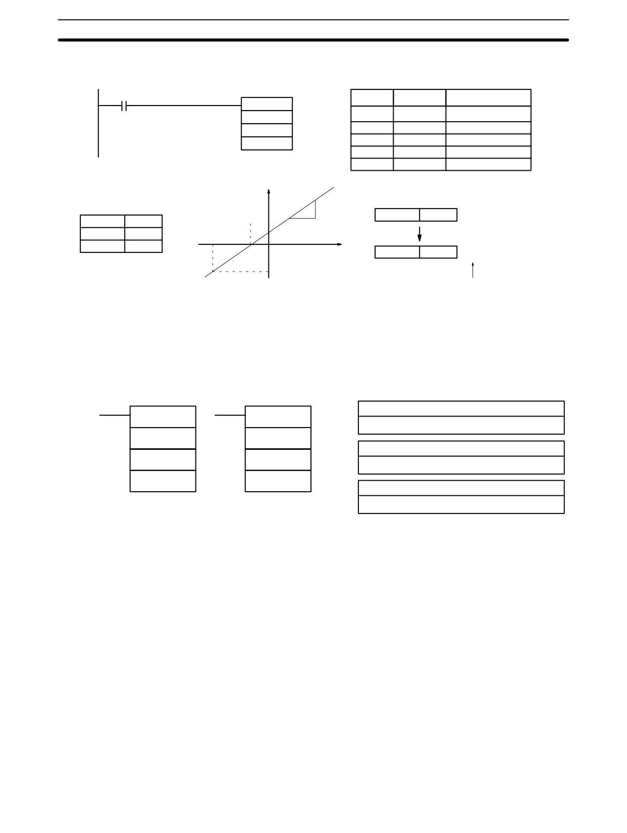
Data Control Instructions
Section
7-18
DM 0000 to DM 0002. The result (#0018) is then written to LR 00 and CY is
turned ON because the result is negative.
05000
Address
Instruction
Operands
@SCL2(--)
200
00000
LD
05000
DM 0000
00001
@SCL2(--)
200
LR 00
DM
0000
LR
00
2
FFFD
IR 200
FFE2
DM 0000
FFFD
3
DM 0001
0003
FFE2
DM 0002
0002
LR 00
0018
CY=1
–0018
CY flag is turned ON because
R+0002
(FFE2-FFFD)
the conversion result is negative.
0003
+2
(-1B) + -18
3
7-18-3
BCD TO SIGNED BINARY SCALING - SCL3(--)
Ladder Symbols
Operand Data Areas
S: Source word
SCL3(--)
@SCL3(--)
IR, SR, AR, DM, HR, LR
S
S
P1: First parameter word
P1
P1
IR, SR, AR, DM, HR, LR
R
R
R: Result word
IR, SR, AR, DM, HR, LR
Limitations
This instruction is available in the CPM2A/CPM2C only.
P1+1 must be BCD.
P1 through P1+4 must be in the same data area.
DM 6144 to DM 6655 cannot be used for R.
Description
SCL3(--) is used to linearly convert a 4-digit 4-digit BCD value to 4-digit signed
hexadecimal. SCL3(--) converts the BCD value according to a specified linear
relationship. The conversion line is defined by the y-intercept and the slope of
the line specified in the parameter words P1 to P1+2.
When the execution condition is OFF, SCL3(--) is not executed. When the
execution condition is ON, SCL3(--) converts the 4-digit BCD value in S to the
4-digit signed hexadecimal value on the line defined by the y-intercept (0, P1)
and the slope (P1+2 ÷ P1+1) and places the result in R. The result is rounded off
to the nearest integer.
The content of S can be 0000 to 9999, but S will be treated as a negative value if
CY=1, so the effective range of S is actually -9999 to 9999. Be sure to set the
desired sign in CY using STC(40) or CLC(41).
Parameter words P1+3 and P1+4 define upper and lower limits for the result. If
the result is greater than the upper limit in P1+3, then the upper limit is written to
420
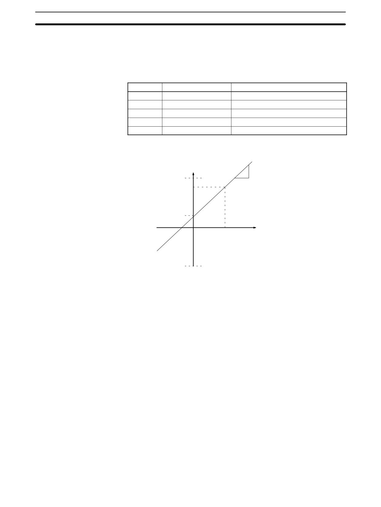
Data Control Instructions
Section
7-18
R. If the result is less than the lower limit in P1+4, then the lower limit is written to
R.
Note The upper and lower limits for a 12-bit Analog Input Unit would be 07FF and
F800.
The following table shows the functions and ranges of the parameter words:
Parameter
Function
Range
P1
x-intercept (signed hex.)
8000 to 7FFF (-32,768 to 32,767)
P1+1
∆X (BCD)
0001 to 9999
P1+2
∆Y (signed hex.)
8000 to 7FFF (-32,768 to 32,767)
P1+3
Upper limit (signed hex.)
8000 to 7FFF (-32,768 to 32,767)
P1+4
Lower limit (signed hex.)
8000 to 7FFF (-32,768 to 32,767)
The following diagram shows the source word, S, converted to R according to
the line defined by the point (0, P1) and slope ∆Y/∆X.
Value after conversion
(Signed hexadecimal)
∆Y
Upper limit
∆X
R
Y-intercept
Value before conversion
(BCD)
S
Lower limit
The result can be calculated by first converting all BCD values to signed binary
and then using the following formula.
R+
ǒDY
S
Ǔ ) P1
DX
Flags
ER:
Indirectly addressed DM word is non-existent. (Content of *DM word is
not BCD, or the DM area boundary has been exceeded.)
The content of S is not BCD.
CY:
CY is not changed by SCL3(--). (CY shows the sign of S before execu-
tion.)
EQ:
ON when the result, R, is 0000.
421
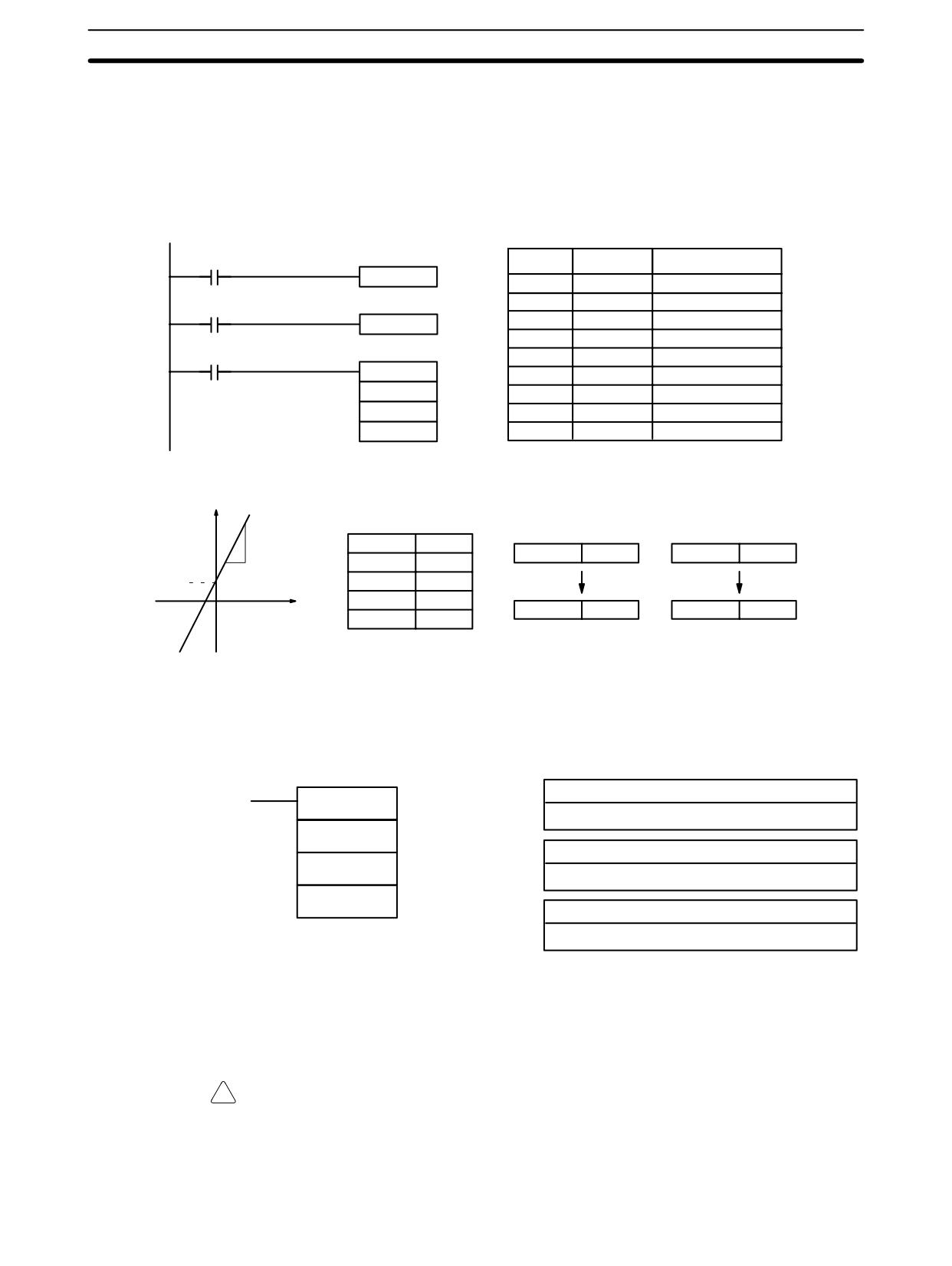
Data Control Instructions
Section 7-18
Example
The status of 00101 determines the sign of the BCD source word in the following
example. If 00101 is ON, then the source word is negative. When 00100 is
turned ON, the BCD source data in LR 02 is converted to signed binary accord-
ing to the parameters in DM 0000 to DM 0004. The result is then written to
DM 0100. (In the second conversion, the signed binary equivalent of -1035 is
less than the lower limit specified in DM 0004, so the lower limit is written to
DM 0100.)
25313
(Always ON)
Address
Instruction
Operands
CLC(41)
00000
LD
25313
00001
CLC(41)
00101
00002
LD
00101
STC(40)
00101
STC(40)
00100
00004
LD
00100
@SCL3(--)
00005
SCL3(--)
LR 02
LR
02
DM 0000
DM
0000
DM 0100
DM
0100
Signed hex.
CY=0
CY=1
6
DM 0000
0005
LR 02
0100
LR 02
1035
DM 0001
0003
3
0005
DM 0002
0006
BCD
DM 0003
07FF
DM 0100
00CD
DM 0100
F800
DM 0004
F800
7-18-4
PID CONTROL - PID(--)
Ladder Symbol
Operand Data Areas
IW: Input data word
PID(--)
IR, SR, AR, DM, HR, LR
IW
P1: First parameter word
P1
IR, SR, DM, HR, LR
OW
OW: Output data word
IR, SR, AR, DM, HR, LR
Limitations
This instruction is available in the CPM2A/CPM2C and SRM1(-V2) only.
DM 6144 to DM 6655 cannot be used for P1 or OW.
P1 to P1+32 must be in the same data area.
!
Caution A total of 33 continuous words starting with P1 must be provided for PID(--) to
operate correctly. Also, PID(--) may not operate dependably in any of the fol-
lowing situations: In interrupt programs, in subroutines, between IL(02) and
ILC(03), between JMP(04) and JME(05), and in step programming
(STEP(08)/SNXT(09)). Do not program PID(--) in these situations.
422
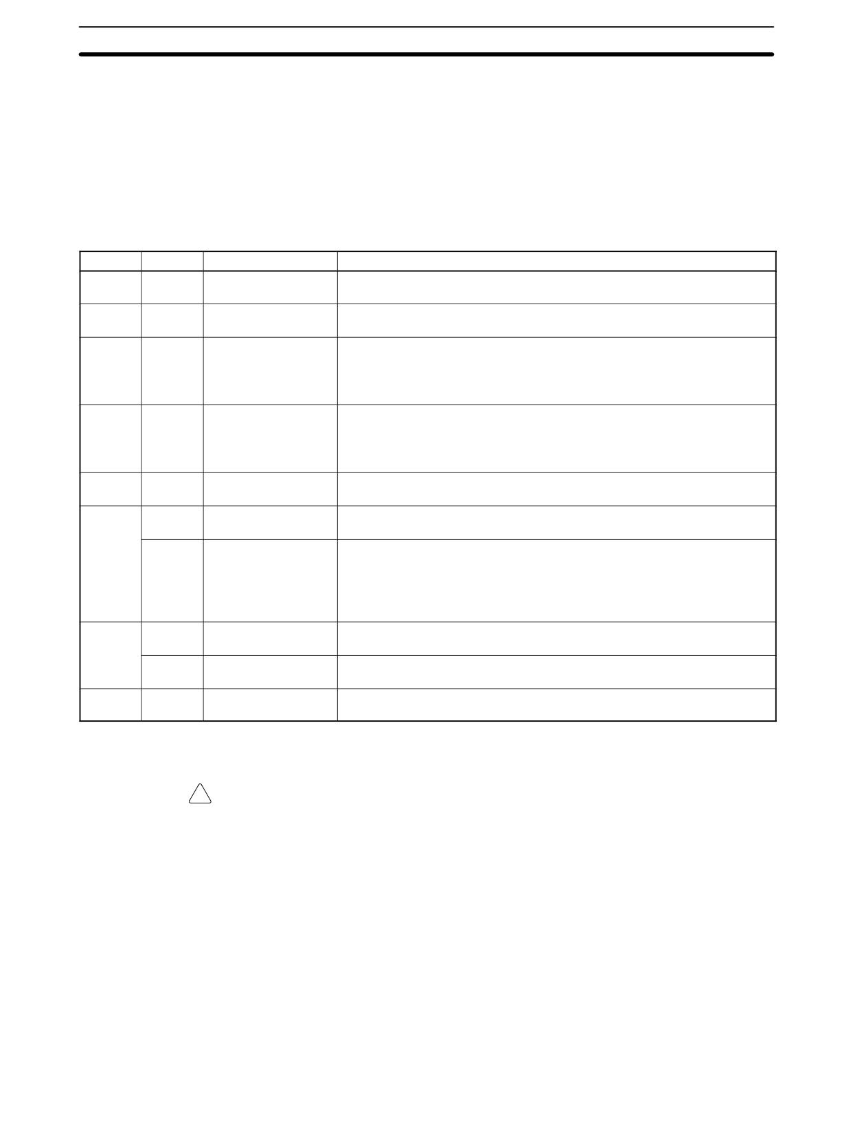
Data Control Instructions
Section 7-18
Description
PID(--) performs PID control based on the parameters specified in P1 through
P1+6.
When the execution condition OFF, PID(--) is not executed. When the execu-
tion condition is ON, PID(--) carries out PID control according to the designated
parameters. It takes the specified input range of binary data from the contents of
IW and carries out the PID action according to the parameters that are set. The
result is then stored as the manipulated variable in OW.
The following table shows the function of the parameter words.
Word
Bits
Parameter name
Function/Setting range
P1
00 to 15
Set value (SV).
This is the target value for PID control. It can be set to any binary number
with the number of bits set by the input range parameter.
P1+1
00 to 15
Proportional band
This parameter specifies the proportional band width/input range ratio from
width.
0.1% to 999.9%. It must be BCD from 0001 to 9999.
P1+2
00 to 15
Integral time (Tik)/
Sets the strength of integral action. Increasing this value strengthens the
sampling period (τ)
integral action. It must be BCD from 0001 to 8191, or 9999. A setting of
9999 disables integral control.
Set the integral time divided by the sampling time.
P1+3
00 to 15
Derivative time
Sets the strength of derivative action. Increasing this value strengthens the
(Tdk)/sampling peri-
derivative action. It must be BCD from 0001 to 8191, or 0000.
od (τ)
(A setting of 0000 disables derivative control.)
Set the derivative time divided by the sampling time.
P1+4
00 to 15
Sampling period (τ)
Sets the interval between samplings of the input data. It must be BCD from
0001 to 1023. The period will be from 0.1 to 102.3 s
P1+5
00 to 03
Operation specifier
Sets reverse or normal operation. Set to 0 to specify reverse operation or
1 to specify normal operation.
04 to 15
Input filter coefficient
Determines the strength of the input filter. The lower the coefficient, the
(α)
weaker the filter.
This setting must be BCD from 100 to 199, or 000. A setting of 000 sets
the default value (0.65) and a setting of 100 to 199 sets the coefficient
from 0.00 to 0.99.
P1+6
00 to 03
Output range
Determines the number of bits of output data. This setting must be be-
tween 0 and 8, which sets the output range between 8 and 16 bits.
08 to 15
Input range
Determines the number of bits of input data. This setting must be between
00 and 08, which sets the input range between 8 and 16 bits.
P1+7 to
00 to 15
Work area
Do not use.
P1+32
(Used by the system.)
!
Caution Changes made to the parameters will not be effective until the execution condi-
tion for PID(--) goes from OFF to ON.
Note Do not use PID(--) in the following situations; it may not be executed properly.
In interrupt programs
In subroutine programs
In interlocked program sections (between IL and ILC)
In jump program sections (between JMP and JME)
In step ladder program section (created with STEP)
When the execution condition is ON, PID(--) performs the PID calculation on
the input data when the sampling period has elapsed. The sampling period is the
time that must pass before input data is read for processing.
423
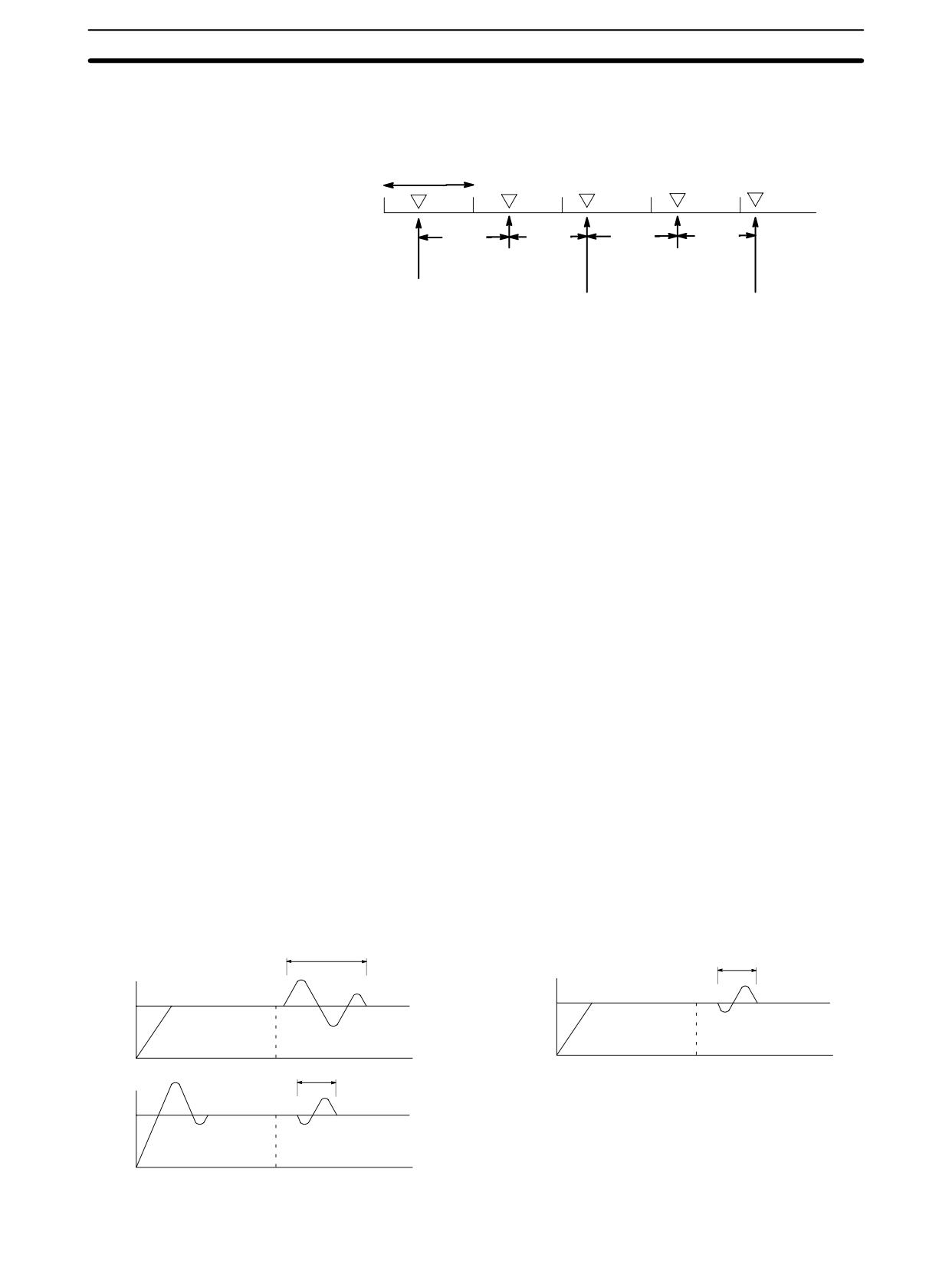
Data Control Instructions
Section
7-18
The following diagram shows the relationship between the sampling period and
PID processing. PID processing is performed only when the sampling period
(100 ms in this case) has elapsed.
1 cycle
70 ms
60 ms
70 ms
70 ms
No processing
PID processing
(70 ms)
(70+30=100 ms,
PID processing
no carryover)
with initial values
PID processing
No processing
(0 ms)
(130 ms, 30 ms carryover)
(60 ms)
PID CONTROL Action
Execution Condition OFF
All data that has been set is retained. When the execution condition is OFF, the
manipulated variable can be written to the output word (OW) to achieve manual
control.
Rising Edge of the Execution Condition
The work area is initialized based on the PID parameters that have been set and
the PID control action is begin. Sudden and radical changes in the manipulated
variable output are not made when starting action to avoid adverse affect on the
controlled system (bumpless operation).
When PID parameters are changed, they first become valid when the execution
condition changes from OFF to ON.
Execution Condition ON
The PID action is executed at the intervals based on the sampling period, ac-
cording to the PID parameters that have been set.
Sampling Period and PID Execution Timing
The sampling period is the time interval to retrieve the measurement data for
carrying out a PID action. PID(--), however, is executed according to CPU
cycle, so there may be cases where the sampling period is exceeded. In such
cases, the time interval until the next sampling is reduced.
PID Control Method
PID control actions are executed by means of PID control with feed-forward con-
trol (two degrees of freedom).
When overshooting is prevented with simple PID control, stabilization of distur-
bances is slowed (1). If stabilization of disturbances is speeded up, on the other
hand, overshooting occurs and response toward the target value is slowed (2).
With feed-forward PID control, there is no overshooting, and response toward
the target value and stabilization of disturbances can both be speeded up (3).
Simple PID Control
Feed-forward PID control
(1)
As the target response is slowed,
Target response
Disturbance response
the disturbance response worsens.
(2)
As the disturbance response is speeded
Overshoot
up, the target response worsens.
424
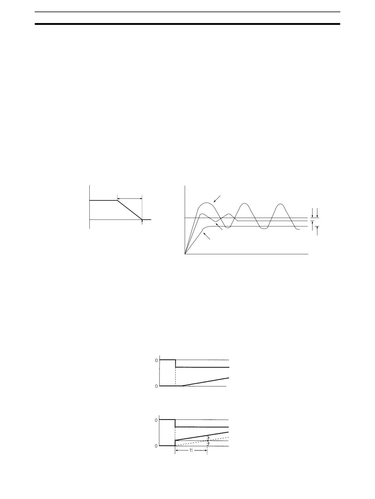
Data Control Instructions
Section
7-18
Control Actions
Proportional Action (P)
Proportional action is an operation in which a proportional band is established
with respect to the set value (SV), and within that band the manipulated variable
(MV) is made proportional to the deviation. An example for reverse operation is
shown in the following illustration
If the proportional action is used and the present value (PV) becomes smaller
than the proportional band, the manipulated variable (MV) is 100% (i.e., the
maximum value). Within the proportional band, the MV is made proportional to
the deviation (the difference between from SV and PV) and gradually decreased
until the SV and PV match (i.e., until the deviation is 0), at which time the MV will
be 0% (i.e., the minimum value). The MV will also be 0% when the PV is larger
than the SV.
The proportional band is expressed as a percentage of the total input range. The
smaller the proportional band, the larger the proportional constant and the stron-
ger the corrective action will be. With proportional action an offset (residual devi-
ation) generally occurs, but the offset can be reduced by making the proportional
band smaller. If it is made too small, however, hunting will occur.
Proportional Action (Reverse Action)
Adjusting the Proportional Band
Proportional
Proportional band too narrow (hunting occurring)
band
100%
Manipulated
Offset
variable
SV
0%
SV
Proportional band just right
Proportional band too wide (large offset)
Integral Action (I)
Combining integral action with proportional action reduces the offset according
to the time that has passed. The strength of the integral action is indicated by the
integral time, which is the time required for the manipulated variable of the inte-
gral action to reach the same level as the manipulated variable of the proportion-
al action with respect to the step deviation, as shown in the following illustration.
The shorter the integral time, the stronger the correction by the integral action
will be. If the integral time is too short, the correction will be too strong and will
cause hunting to occur.
Integral Action
Step response
Deviation
Manipulated
variable
Pi Action and Integral Time
Step response
Deviation
PI action
I action
P action
Manipulated
variable
Ti: Integral time
425
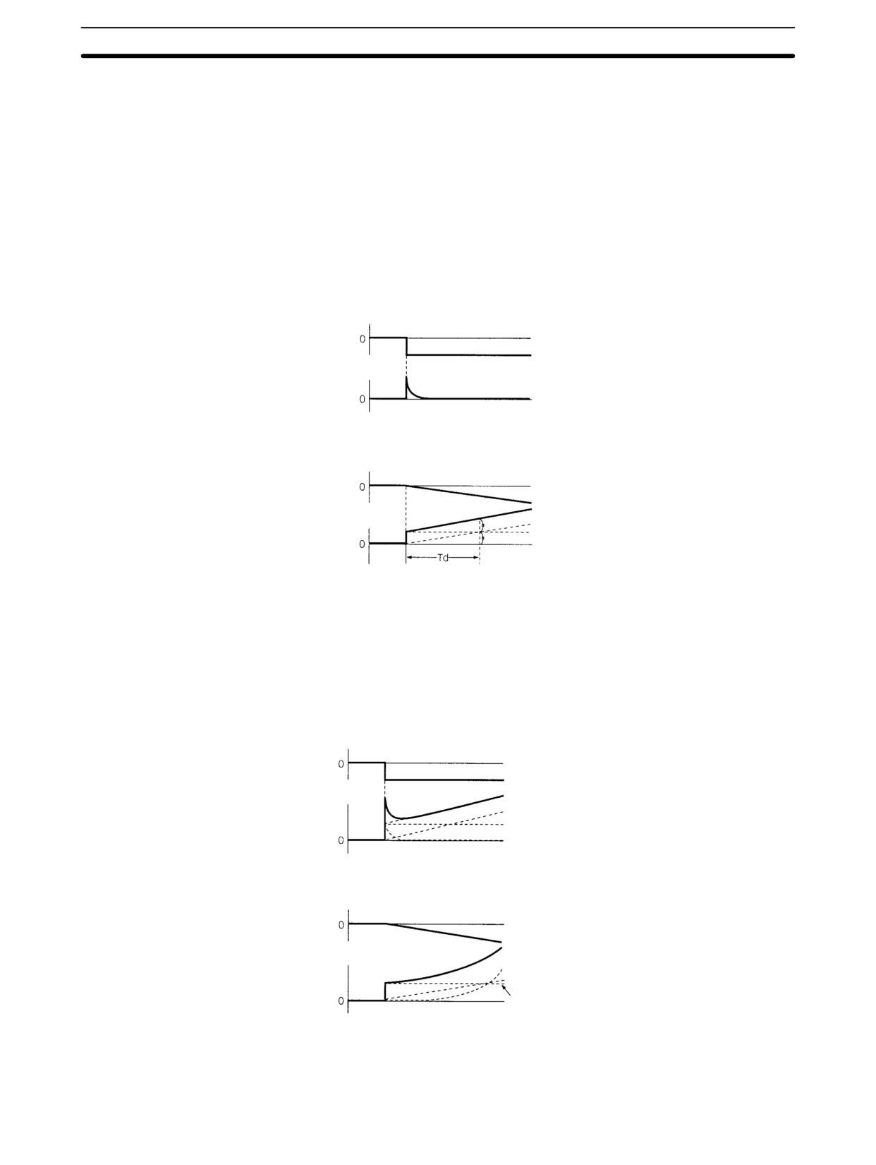
Data Control Instructions
Section
7-18
Derivative Action (D)
Proportional action and integral action both make corrections with respect to the
control results, so there is inevitably a response delay. Derivative action com-
pensates for that drawback. In response to a sudden disturbance it delivers a
large manipulated variable and rapidly restores the original status. A correction
is executed with the manipulated variable made proportional to the incline (de-
rivative coefficient) caused by the deviation.
The strength of the derivative action is indicated by the derivative time, which is
the time required for the manipulated variable of the derivative action to reach
the same level as the manipulated variable of the proportional action with re-
spect to the step deviation, as shown in the following illustration. The longer the
derivative time, the stronger the correction by the derivative action will be.
Derivative Action
Step response
Deviation
Manipulated
variable
PD Action and Derivative Time
Ramp response
Deviation
PD action
P action
D action
Manipulated
variable
Td: Derivative time
PID Action
PID action combines proportional action (P), integral action (I), and derivative
action (D). It produces superior control results even for control objects with dead
time. It employs proportional action to provide smooth control without hunting,
integral action to automatically correct any offset, and derivative action to speed
up the response to disturbances.
Step Response of PID Control Action Output
Step response
Deviation
PID action
I action
P action
Manipulated
D action
variable
Ramp Response of PID Control Action Output
Ramp response
Deviation
PID action
I action
P action
Manipulated
D action
variable
Direction of Action
When using PID action, select either of the following two control directions. In
either direction, the MV increases as the difference between the SV and the PV
increases.
426
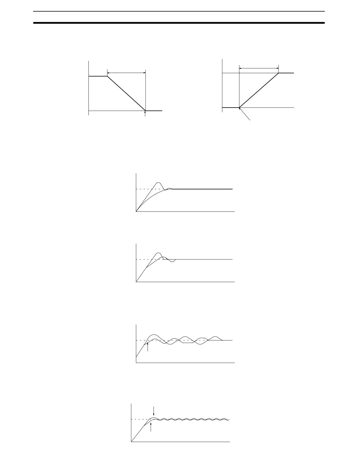
Data Control Instructions
Section
7-18
• Forward action: MV is increased when the PV is larger than the SV.
• Reverse action: MV is increased when the PV is smaller than the SV.
Reverse Action
Forward Action
Proportional
Proportional
band
band
100%
100%
Manipulated
Manipulated
variable
variable
0%
0%
Low
High
Low
High
temperature
SV
temperature
temperature
temperature
SV
Adjusting PID Parameters
The general relationship between PID parameters and control status is shown
below.
• When it is not a problem if a certain amount of time is required for stabilization
(settlement time), but it is important not to cause overshooting, then enlarge
the proportional band.
Control by measured PID
SV
When P is enlarged
• When overshooting is not a problem but it is desirable to quickly stabilize con-
trol, then narrow the proportional band. If the proportional band is narrowed too
much, however, then hunting may occur.
When P is narrowed
SV
Control by measured PID
• When there is broad hunting, or when operation is tied up by overshooting and
undershooting, it is probably because integral action is too strong. The hunting
will be reduced if the integral time is increased or the proportional band is en-
larged.
Control by measured PID
(when loose hunting occurs)
SV
Enlarge I or P.
• If the period is short and hunting occurs, it may be that the control system re-
sponse is quick and the derivative action is too strong. In that case, set the de-
rivative action lower.
Control by measured PID
(when hunting occurs in a short period)
SV
Lower D.
427
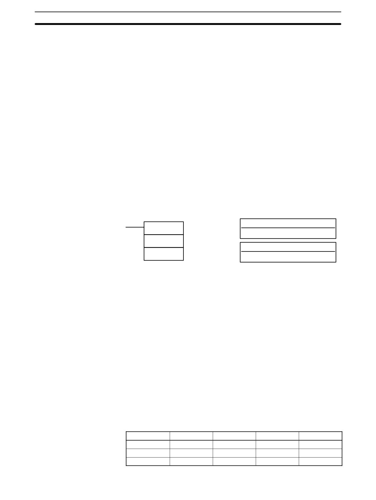
Comparison Instructions
Section
7-19
Flags
ER:
There is an error in the parameter settings.
The cycle time is more than twice as long as the sampling period, so
PID(--) cannot be executed accurately. PID(--) will be executed in this
case.
P1 and P1+32 are not in the same area or a parameter setting is not
within the specified range.
Indirectly addressed DM word is non-existent. (Content of *DM word is
not BCD, or the DM area boundary has been exceeded.)
CY:
ON when PID processing is being performed. (OFF when the sampling
period has not elapsed.)
7-19 Comparison Instructions
7-19-1
COMPARE - CMP(20)
Ladder Symbols
Operand Data Areas
Cp1: First compare word
CMP(20)
IR, SR, AR, DM, HR, TC, LR, #
Cp1
Cp2: Second compare word
Cp2
IR, SR, AR, DM, HR, TC, LR, #
Limitations
When comparing a value to the PV of a timer or counter, the value must be in
BCD.
Description
When the execution condition is OFF, CMP(20) is not executed. When the
execution condition is ON, CMP(20) compares Cp1 and Cp2 and outputs the
result to the GR, EQ, and LE flags in the SR area.
Precautions
Placing other instructions between CMP(20) and the operation which accesses
the EQ, LE, and GR flags may change the status of these flags. Be sure to ac-
cess them before the desired status is changed.
Flags
ER:
Indirectly addressed DM word is non-existent. (Content of *DM word is
not BCD, or the DM area boundary has been exceeded.)
EQ:
ON if Cp1 equals Cp2.
LE:
ON if Cp1 is less than Cp2.
GR:
ON if Cp1 is greater than Cp2.
Flag
Address
C1 < C2
C1 = C2
C1 > C2
GR
25505
OFF
OFF
ON
EQ
25506
OFF
ON
OFF
LE
25507
ON
OFF
OFF
428
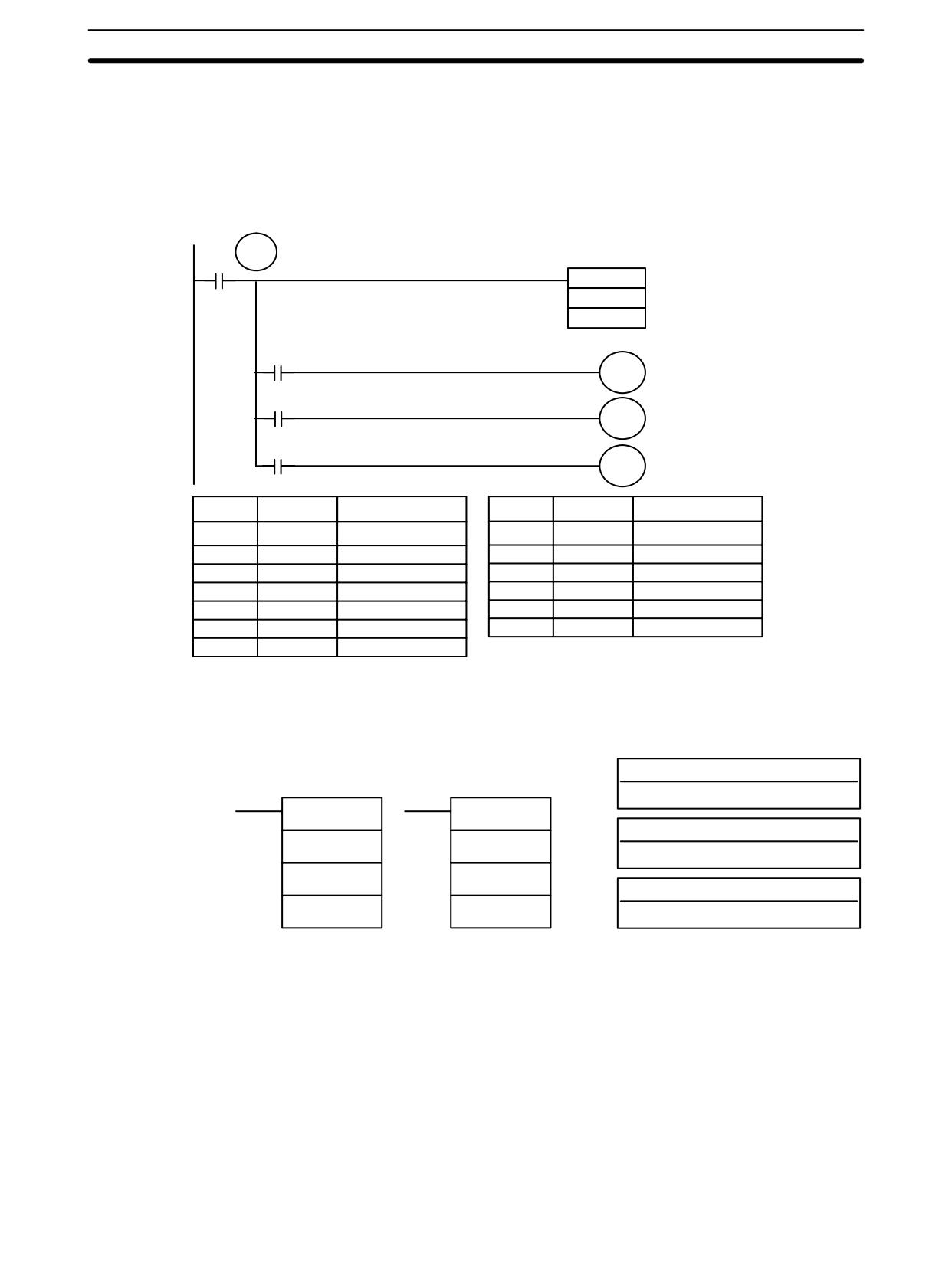
Comparison Instructions
Section
7-19
Example:
The following example shows how to save the comparison result immediately. If
Saving CMP(20) Results
the content of HR 09 is greater than that of DM 0000, 20000 is turned ON; if the
two contents are equal, 20001 is turned ON; if content of HR 09 is less than that
of DM 0000, 20002 is turned ON. In some applications, only one of the three
OUTs would be necessary, making the use of TR 0 unnecessary. With this type
of programming, 20000, 20001, and 20002 are changed only when CMP(20) is
executed.
TR
0
00000
CMP(20)
HR 09
DM 0000
25505
20000
Greater Than
25506
20001
Equal
25507
20002
Less Than
Address
Instruction
Operands
Address
Instruction
Operands
00000
LD
00000
00005
LD
TR
0
00001
OUT
TR
0
00006
AND
25506
00002
CMP(20)
00007
OUT
20001
HR
09
00008
LD
TR
0
DM
0000
00009
AND
25507
00003
AND
25505
00010
OUT
20002
00004
OUT
20000
7-19-2
TABLE COMPARE - TCMP(85)
Operand Data Areas
Ladder Symbols
CD: Compare data
IR, SR, DM, HR, TC, LR, #
TCMP(85)
@TCMP(85)
TB: First comparison table word
CD
CD
IR, SR, DM, HR, TC, LR
TB
TB
R: Result word
R
R
IR, SR, DM, HR, TC, LR
Limitations
DM 6144 to DM 6655 cannot be used for R.
Description
When the execution condition is OFF, TCMP(85) is not executed. When the
execution condition is ON, TCMP(85) compares CD to the content of TB, TB+1,
TB+2, ..., and TB+15. If CD is equal to the content of any of these words, the
corresponding bit in R is set, e.g., if the CD equals the content of TB, bit 00 is
turned ON, if it equals that of TB+1, bit 01 is turned ON, etc. The rest of the bits in
R will be turned OFF.
Flags
ER:
The comparison table (i.e., TB through TB+15) exceeds the data area.
Indirectly addressed DM word is non-existent. (Content of *DM word is
not BCD, or the DM area boundary has been exceeded.)
429
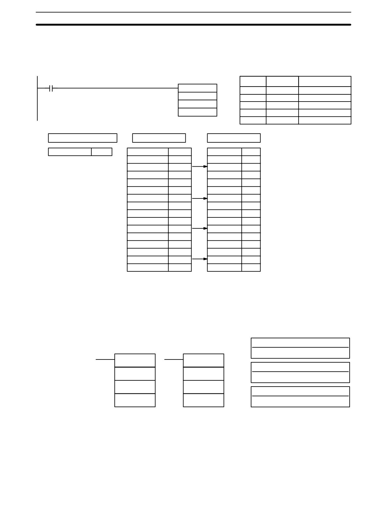
Comparison Instructions
Section
7-19
The following example shows the comparisons made and the results provided
Example
for TCMP(85). Here, the comparison is made during each cycle when IR 00000
is ON.
00000
Address
Instruction
Operands
TCMP(85)
00000
LD
00000
HR 00
00001
TCMP(85)
DM 0000
HR
00
216
DM
0000
216
CD: HR 00
Upper limits
R: 216
HR
00
0210
DM 0000
0100
IR 21000
0
Compare the data in IR 001
DM 0001
0200
IR 21001
0
with the given ranges.
DM 0002
0210
IR 21002
1
DM 0003
0400
IR 21003
0
DM 0004
0500
IR 21004
0
DM 0005
0600
IR 21005
0
DM 0006
0210
IR 21006
1
DM 0007
0800
IR 21007
0
DM 0008
0900
IR 21008
0
DM 0009
1000
IR 21009
0
DM 0010
0210
IR 21010
1
DM 0011
1200
IR 21011
0
DM 0012
1300
IR 21012
0
DM 0013
1400
IR 21013
0
DM 0014
0210
IR 21014
1
DM 0015
1600
IR 21015
0
7-19-3
BLOCK COMPARE - BCMP(68)
Operand Data Areas
Ladder Symbols
CD: Compare data
IR, SR, AR, DM, HR, TC, LR, #
BCMP(68)
@BCMP(68)
CB: First comparison block word
CD
CD
IR, SR, DM, HR, TC, LR
CB
CB
R: Result word
R
R
IR, SR, AR, DM, HR, TC, LR
Note BCMP(68) is an expansion instruction for the SRM1(-V2). The function code 68
is the factory setting and can be changed for the SRM1(-V2) if desired.
Limitations
Each lower limit word in the comparison block must be less than or equal to the
upper limit.
DM 6144 to DM 6655 cannot be used for R.
430
Comparison Instructions
Section
7-19
Description
When the execution condition is OFF, BCMP(68) is not executed. When the
execution condition is ON, BCMP(68) compares CD to the ranges defined by a
block consisting of CB, CB+1, CB+2, ..., CB+31. Each range is defined by two
words, the first one providing the lower limit and the second word providing the
upper limit. If CD is found to be within any of these ranges (inclusive of the upper
and lower limits), the corresponding bit in R is set. The comparisons that are
made and the corresponding bit in R that is set for each true comparison are
shown below. The rest of the bits in R will be turned OFF.
CB ≤ CD ≤ CB+1
Bit 00
CB+2 ≤ CD ≤ CB+3
Bit 01
CB+4 ≤ CD ≤ CB+5
Bit 02
CB+6 ≤ CD ≤ CB+7
Bit 03
CB+8 ≤ CD ≤ CB+9
Bit 04
CB+10 ≤ CD ≤ CB+11
Bit 05
CB+12 ≤ CD ≤ CB+13
Bit 06
CB+14 ≤ CD ≤ CB+15
Bit 07
CB+16 ≤ CD ≤ CB+17
Bit 08
CB+18 ≤ CD ≤ CB+19
Bit 09
CB+20 ≤ CD ≤ CB+21
Bit 10
CB+22 ≤ CD ≤ CB+23
Bit 11
CB+24 ≤ CD ≤ CB+25
Bit 12
CB+26 ≤ CD ≤ CB+27
Bit 13
CB+28 ≤ CD ≤ CB+29
Bit 14
CB+30 ≤ CD ≤ CB+31
Bit 15
Flags
ER:
The comparison block (i.e., CB through CB+31) exceeds the data area.
Indirectly addressed DM word is non-existent. (Content of *DM word is
not BCD, or the DM area boundary has been exceeded.)
431
Comparison Instructions
Section
7-19
Example
The following example shows the comparisons made and the results provided
for BCMP(68). Here, the comparison is made during each cycle when IR 00000
is ON.
00000
Address
Instruction
Operands
BCMP(68)
HR 00
00000
LD
00000
DM 0010
00001
BCMP(68)
HR
00
LR 05
DM
0010
LR
05
HR 00
Lower limits
Upper limits
R:LR 05
HR 00
0210
DM 0010
0000
DM 0011
0100
LR 0500
0
Compare data in IR 001
DM 0012
0101
DM 0013
0200
LR 0501
0
(which contains 0210) with
DM 0014
0201
DM 0015
0300
LR 0502
1
the given ranges.
DM 0016
0301
DM 0017
0400
LR 0503
0
DM 0018
0401
DM 0019
0500
LR 0504
0
DM 0020
0501
DM 0021
0600
LR 0505
0
DM 0022
0601
DM 0023
0700
LR 0506
0
DM 0024
0701
DM 0025
0800
LR 0507
0
DM 0026
0801
DM 0027
0900
LR 0508
0
DM 0028
0901
DM 0029
1000
LR 0509
0
DM 0030
1001
DM 0031
1100
LR 0510
0
DM 0032
1101
DM 0033
1200
LR 0511
0
DM 0034
1201
DM 0035
1300
LR 0512
0
DM 0036
1301
DM 0037
1400
LR 0513
0
DM 0038
1401
DM 0039
1500
LR 0514
0
DM 0040
1501
DM 0041
1600
LR 0515
0
7-19-4
DOUBLE COMPARE - CMPL(60)
Ladder Symbols
Operand Data Areas
Cp1: First word of first compare word pair
CMPL(60)
IR, SR, AR, DM, HR, TC, LR
Cp1
Cp2: First word of second compare word pair
Cp2
IR, SR, AR, DM, HR, TC, LR
--
Note CMPL(60) is an expansion instruction for the SRM1(-V2). The function code 60
is the factory setting and can be changed for the SRM1(-V2) if desired.
Limitations
Cp1 and Cp1+1 must be in the same data area.
Cp2 and Cp2+1 must be in the same data area.
Set the third operand to 000.
Description
When the execution condition is OFF, CMPL(60) is not executed. When the
execution condition is ON, CMPL(60) joins the 4-digit hexadecimal content of
Cp1+1 with that of Cp1, and that of Cp2+1 with that of Cp2 to create two 8-digit
hexadecimal numbers, Cp+1,Cp1 and Cp2+1,Cp2. The two 8-digit numbers are
then compared and the result is output to the GR, EQ, and LE flags in the SR
area.
Precautions
Placing other instructions between CMPL(60) and the operation which ac-
cesses the EQ, LE, and GR flags may change the status of these flags. Be sure
to access them before the desired status is changed.
432
Comparison Instructions
Section
7-19
Flags
ER:
Indirectly addressed DM word is non-existent. (Content of *DM word is
not BCD, or the DM area boundary has been exceeded.)
GR:
ON if Cp1+1,Cp1 is greater than Cp2+1,Cp2.
EQ:
ON if Cp1+1,Cp1 equals Cp2+1,Cp2.
LE:
ON if Cp1+1,Cp1 is less than Cp2+1,Cp2.
Example:
The following example shows how to save the comparison result immediately. If
Saving CMPL(60) Results
the content of HR 10, HR 09 is greater than that of DM 0001, DM 0000, then
20000 is turned ON; if the two contents are equal, 20001 is turned ON; if content
of HR 10, HR 09 is less than that of DM 0001, DM 0000, then 20002 is turned ON.
In some applications, only one of the three OUTs would be necessary, making
the use of TR 0 unnecessary. With this type of programming, 20000, 20001, and
20002 are changed only when CMPL(60) is executed.
TR
Address
Instruction
Operands
0
00000
00000
LD
00000
CMPL(60)
00001
OUT
TR
0
HR 09
00002
CMPL(60)
DM 0000
HR
09
---
DM
0000
25505
00003
AND
25505
20000
Greater Than
00004
OUT
20000
00005
LD
TR
0
25506
00006
AND
25506
20001
Equal
00007
OUT
20001
00008
LD
TR
0
00009
AND
25507
25507
00010
OUT
20002
20002
Less Than
7-19-5
AREA RANGE COMPARE - ZCP(--)
Operand Data Areas
Ladder Symbol
CD: Compare data
IR, SR, AR, DM, HR, TC, LR, #
ZCP(--)
LL: Lower limit of range
CD
IR, SR, AR, DM, HR, TC, LR, #
LL
UL: Upper limit of range
UL
IR, SR, AR, DM, HR, TC, LR, #
Limitations
This instruction is available in the CPM2A/CPM2C/SRM1(-V2) only.
LL must be less than or equal to UL.
Description
When the execution condition is OFF, ZCP(--) is not executed. When the
execution condition is ON, ZCP(--) compares CD to the range defined by lower
limit LL and upper limit UL and outputs the result to the GR, EQ, and LE flags in
the SR area. The resulting flag status is shown in the following table.
Comparison result
Flag status
GR (SR 25505)
EQ (SR 25506)
LE (SR 25507)
CD < LL
0
0
1
LL ≤ CD ≤ UL
0
1
0
UL < CD
1
0
0
433
Comparison Instructions
Section
7-19
Precautions
Placing other instructions between ZCP(--) and the operation which accesses
the EQ, LE, and GR flags may change the status of these flags. Be sure to ac-
cess them before the desired status is changed.
Flags
ER:
Indirectly addressed DM word is non-existent. (Content of *DM word is
not BCD, or the DM area boundary has been exceeded.)
LL is greater than UL.
EQ:
ON if LL ≤ CD ≤ UL
LE:
ON if CD < LL.
GR:
ON if CD > UL.
Example
In the following example, the content of IR 200 (#6FA4) is compared to the range
#0010 to #AB1F. Since #0010 ≤ #6FA4 ≤ #AB1F, the EQ flag and IR 10101 are
turned ON.
TR
0
00000
ZCP(--)
200
#0010
#AB1F
25505
Greater Than
01000
(above range)
25506
01001
Equal
(within range)
25507
01002
Less Than
(below range)
Address
Instruction
Operands
Address
Instruction
Operands
00000
LD
00000
00004
OUT
01000
00001
OUT
TR
0
00005
LD
TR
0
00002
ZCP(--)
00006
AND
25506
200
00007
OUT
01001
#
0010
00008
LD
TR
0
#
AB1F
00009
AND
25507
00003
AND
25505
00010
OUT
01002
20000: OFF
LL: #0010
CD: 200
UL: #AB1F
20001: ON
<
<
0
0
1
0
6
F
A
4
A
B
1
F
20002: OFF
7-19-6
DOUBLE AREA RANGE COMPARE - ZCPL(--)
Operand Data Areas
Ladder Symbol
CD: Compare data
IR, SR, AR, DM, HR, LR
ZCPL(--)
LL: Lower limit of range
CD
IR, SR, AR, DM, HR, LR
LL
UL: Upper limit of range
UL
IR, SR, AR, DM, HR, LR
434
Conversion Instructions
Section
7-20
Limitations
This instruction is available in the CPM2A/CPM2C only.
The 8-digit value in LL+1,LL must be less than or equal to UL+1,UL.
Description
When the execution condition is OFF, ZCPL(--) is not executed. When the
execution condition is ON, ZCPL(--) compares the 8-digit value in CD, CD+1 to
the range defined by lower limit LL+1,LL and upper limit UL+1,UL and outputs
the result to the GR, EQ, and LE flags in the SR area. The resulting flag status is
shown in the following table.
Comparison result
Flag status
GR
EQ
LE
(SR 25505)
(SR 25506)
(SR 25507)
CD , CD+1< LL+1,LL
0
0
1
LL+1,LL ≤ CD, CD+1 ≤ UL+1,UL
0
1
0
UL+1,UL < CD, CD+1
1
0
0
Precautions
Placing other instructions between ZCPL(--) and the operation which accesses
the EQ, LE, and GR flags may change the status of these flags. Be sure to ac-
cess them before the desired status is changed.
Flags
ER:
Indirectly addressed DM word is non-existent. (Content of *DM word is
not BCD, or the DM area boundary has been exceeded.)
LL+1,LL is greater than UL+1,UL.
EQ:
ON if LL+1,LL ≤ CD, CD+1 ≤ UL+1,UL
LE:
ON if CD, CD+1 < LL+1,LL.
GR:
ON if CD, CD+1 > UL+1,UL.
7-20 Conversion Instructions
7-20-1
BCD-TO-BINARY - BIN(23)
Ladder Symbols
Operand Data Areas
S: Source word (BCD)
BIN(23)
@BIN(23)
IR, SR, AR, DM, HR, TC, LR
S
S
R: Result word
R
R
IR, SR, AR, DM, HR, LR
Limitations
DM 6144 to DM 6655 cannot be used for R.
Description
When the execution condition is OFF, BIN(23) is not executed. When the execu-
tion condition is ON, BIN(23) converts the BCD content of S into the numerically
equivalent binary bits, and outputs the binary value to R. Only the content of R is
changed; the content of S is left unchanged.
BCD
S
Binary
R
BIN(23) can be used to convert BCD to binary so that displays on the Program-
ming Console or any other programming device will appear in hexadecimal rath-
er than decimal. It can also be used to convert to binary to perform binary arith-
metic operations rather than BCD arithmetic operations, e.g., when BCD and
binary values must be added.
435