SYSMAC CPM1/CPM1A/CPM2A/CPM2C/SRM1(–V2). Programmable Controllers (2001) - page 4
CPM2A/CPM2C Communications Functions
Section
4-3
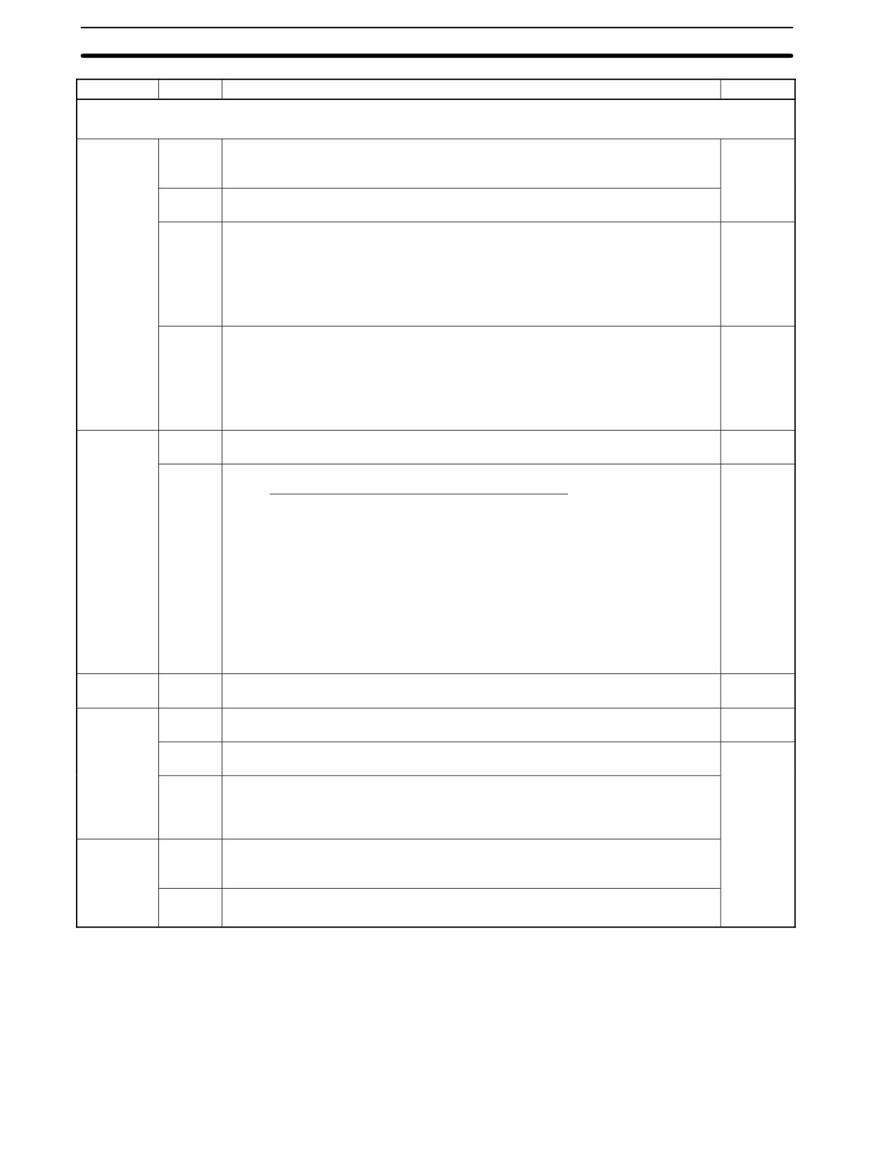
When using an NT Link with a CPM2A/CPM2C PC, the following settings must
PC Setup
be made to the PC Setup (DM 6645) using a Programming Device.
Word
Bit
Function
Setting
DM 6645
00 to 03
Port settings
Any
0: Standard (1 start bit, 7-bit data, 2 stop bits, even parity, 9,600 bps; Host Link
unit number: 0)
1: Settings in DM 6646
(Other settings will cause a non-fatal error, the default setting (00) will be used, and
AR 1302 will turn ON.)
04 to 07
CTS control settings
Any
0: Disable
1: Set
08 to 11
Link area for 1:1 PC Link
Any
0: LR 00 to LR 15
(Other settings: Disabled)
12 to 15
Communications mode
4
0: Host Link; 1: No-protocol; 2: 1:1 PC Link Slave; 3: 1:1 PC Link Master;
4: 1:1 NT Link
(Other settings will cause a non-fatal error, the Host Link setting will be used, and
AR 1302 will turn ON.)
For information on the 1:1 NT Link settings of an OMRON Programmable Termi-
nal, refer to that PT’s Operation Manual.
Connecting the Cables
This section describes RS-232C connections.
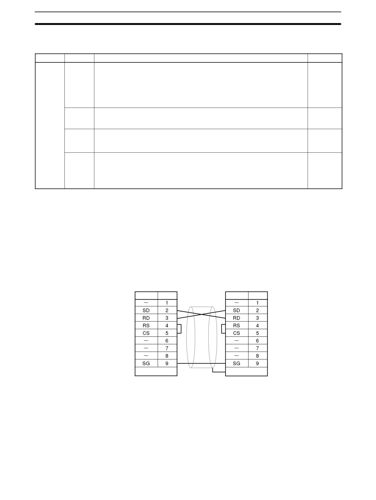
The RS-232C port on the Programmable Terminal and the RS-232C port on the
CPM2A/CPM2C or CPM1-CIF01 RS-232C Adapter are connected as shown in
the following diagram when there is no CTS control on the RS-232C port. With
the CPM2C, the CPM2C-CN111 and CS1W-CN118 connecting cables are
used.
OMRON PT
RS-232C port
Signal Pin No.
Signal Pin No.
Recommended cables:
XW2Z-200T:
2m
XW2Z-500T:
5m
Hood
Hood
4-3-4
One-to-one PC Link Communications
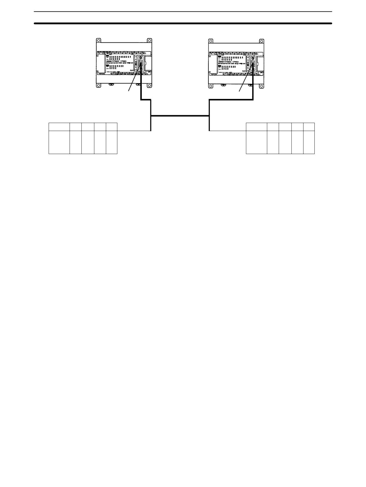
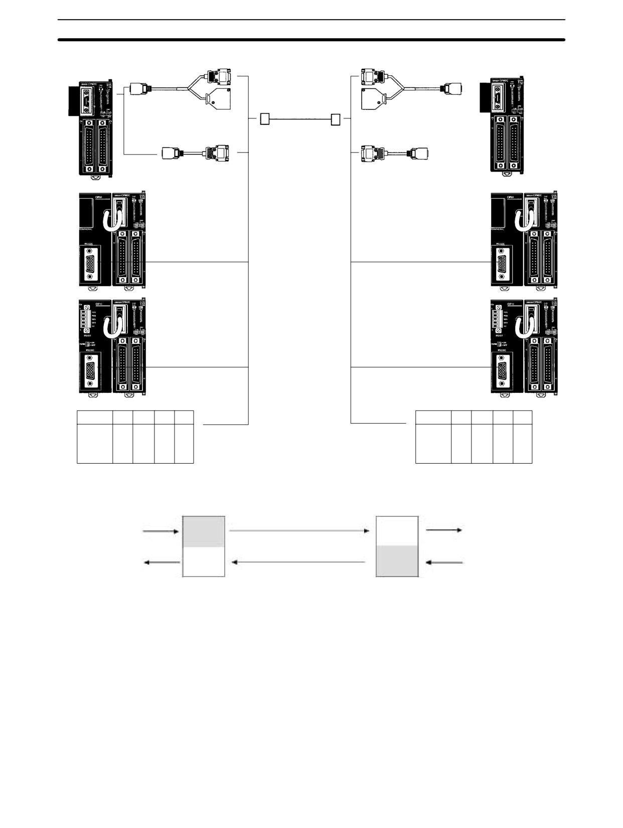
A 1:1 PC Link of up to 256 bits (LR0000 to LR1515) can be created with the data
area of another CPM2A/CPM2C, CQM1, CPM1, CPM1A, SRM1(-V2), or a
C200HX/HG/HE PC, where one serves as the Master, the other as a Slave.
There is no need for a communications program on the PC.
The 1:1 PC Link can be used with an RS-232C port.
One-to-one PC Link
259
CPM2A/CPM2C Communications Functions
Section
4-3
CPM2A CPU Unit
CPM2A CPU Unit
RS-232C port
RS-232C port
OMRON PC (CQM1, CPM1, CPM1A, CPM2C,
OMRON PC (CQM1, CPM1, CPM1A, CPM2C,
SRM1(-V2), C200HS, or C200HX/HG/HE)
SRM1(-V2), C200HS, or C200HX/HG/HE)
260
CPM2A/CPM2C Communications Functions
Section
4-3
1:1 Link Master
RS-232C port (D-sub 9-pin)
RS-232C port (D-sub 9-pin)
1:1 Link Slave
CPM2C CPU Unit
CPM2C CPU Unit
CPM2C-CN111
(0.1 m)
CPM2C-CN111 (0.1 m)
Connecting Cable
XW2Z-200T (2 m)
XW2Z-500T (5 m)
CS1W-CN118
CS1W-CN118 (0.1 m)
(0.1 m)
CPM2C-CIF01
CPM2C-CIF01
CPM2C-CIF11
CPM2C-CIF11
OMRON PC (CQM1, CPM1, CPM1A, CPM2A,
OMRON PC (CQM1, CPM1, CPM1A, CPM2A,
SRM1(-V2), C200HS, or C200HX/HG/HE)
SRM1(-V2), C200HS, or C200HX/HG/HE)
Master
Slave
Link bits
Link bits
LR00
LR00
Write
Read
Write
Read
area
area
LR07
LR07
LR08
LR08
Read
Write
Read
area
area
Write
LR15
LR15
Note Even though the peripheral port on the CPM2C-CIF01 can output RS-232C, this port cannot be used for
one-to-one link communications.
261
CPM2A/CPM2C Communications Functions
Section
4-3
PC Links with Other PCs
The link relay area on CPM2A/CPM2C PCs is only 16 words, LR00 to LR15.
When performing a 1:1 PC Link with a CPM2A/CPM2C PC and a CQM1,
C200HS, or C200HX/HE/HG use the corresponding 16 words, LR00 to LR15 on
the CQM1, C200HS, or C200HX/HE/HG PC. A 1:1 PC Link with a CPM2A/
CPM2C PC cannot be formed using LR16 to LR 63.
Application Procedure
Use the settings in the PC Setup (DM6645 to DM 6649) for
Setting communications.
RS-232C communications.
(Turn OFF the Communications switch on the CPM2A’s CPU
Unit or pin 1 of the DIP Switch on the CPM2C’s CPU Unit.)
Connecting the cables
Connect a 1:1 PC Link with another PC.
Communications Switch
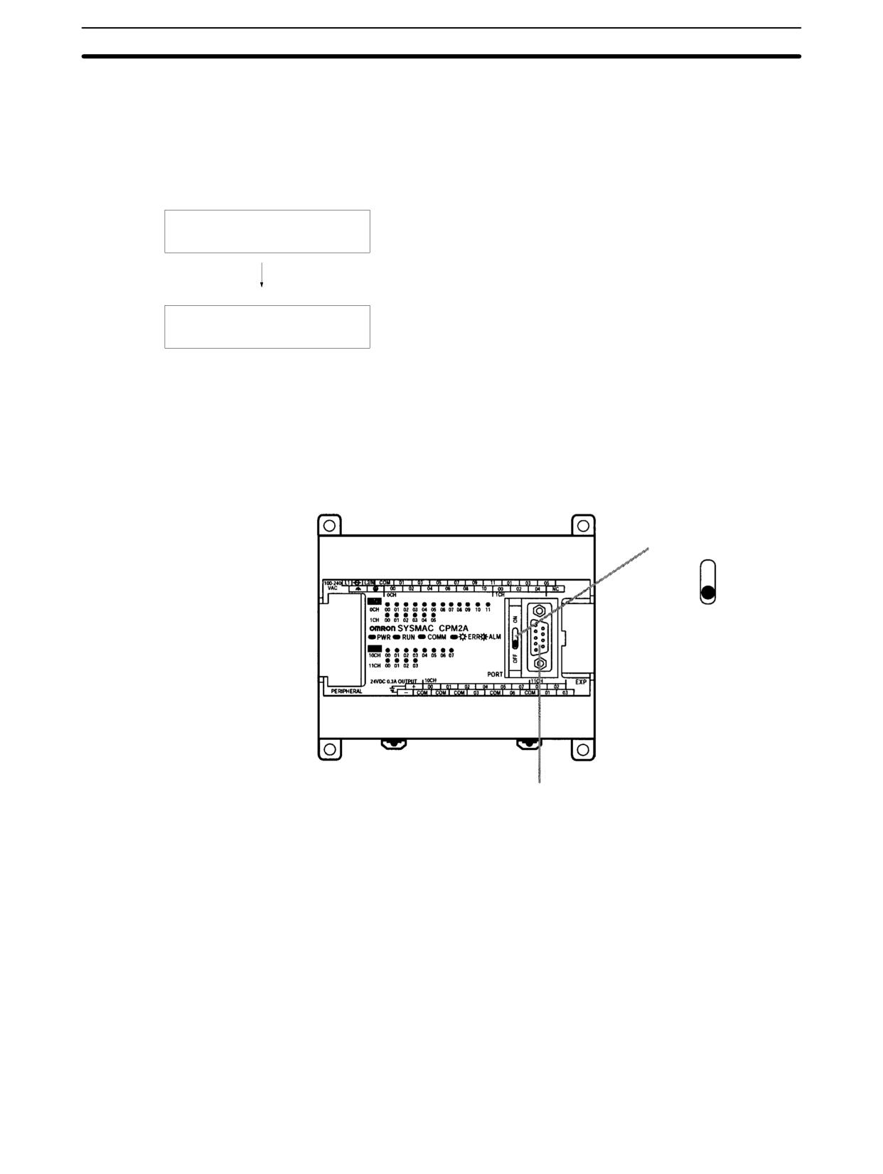
The CPM2A’s communications are controlled by the communications switch on
Setting
the front of the CPU Unit and the CPM2C’s communications are controlled by
the DIP switch on the front of the CPU Unit.
CPM2A Communications Switch Setting
Turn OFF the Communications switch when using 1:1 PC Link communications.
One-to-one PC Link communications will not be possible if the communications
switch is ON.
Communications switch
ON
OFF
RS-232C port
262
CPM2A/CPM2C Communications Functions
Section
4-3
CPM2C DIP Switch Settings
Turn OFF pin 1 of the DIP switch when using 1:1 PC Link communications so
that communications through the RS-232C port are governed by the settings in
the PC Setup (DM 6645 to DM 6649).
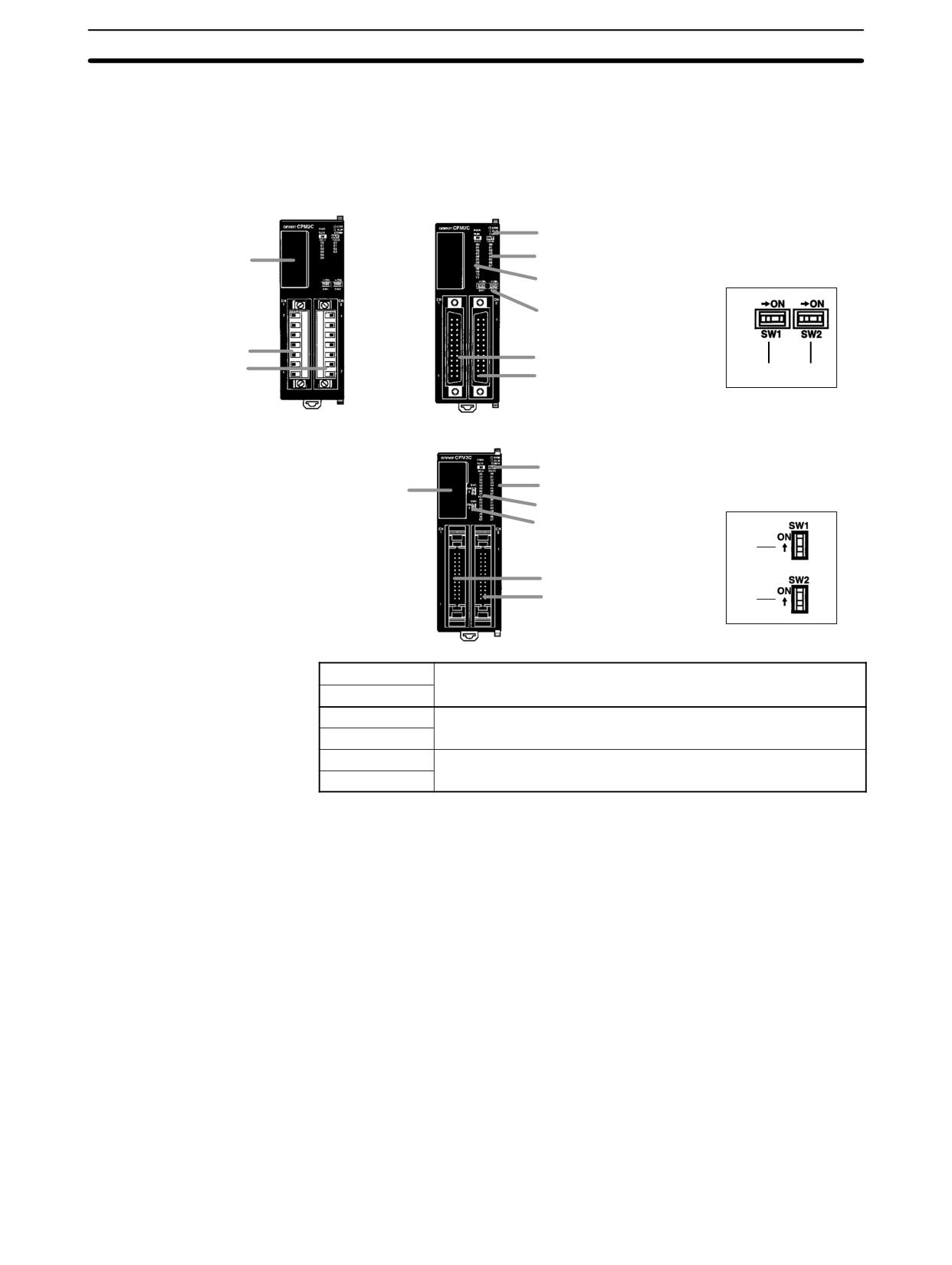
Front View
CPU Unit with Relay Out-
CPU Unit with Transistor Outputs
puts via Terminal Block
via Fujitsu-compatible Connector
4. Status indicators
6. Output indicators
7. Communications port
DIP switch for Units
5. Input indicators
with 10/20 I/O points
8. Communications switch
9. Customize switch
2. Input terminals
2. Input connector
3. Output terminals
3. Output connector
(8)
(9)
CPU Unit with Transistor Outputs
via MIL Connector
4. Status indicators
6. Output indicators
DIP switch for Units
7. Communications port
with 32 I/O points
5. Input indicators
8. Communications switch
9. Customize switch
(8)
2. Input connector
3. Output connector
(9)
Pin settings
RS-232C port communications
Pin 1
OFF
Governed by the PC Setup
(DM 6645 to DM 6649)
OFF
ON
Governed by standard settings
ON
263
SRM1(-V2) Communications Functions
Section
4-4
When creating a 1:1 PC Link with a CPM2A/CPM2C PC, use a Programming
PC Setup
Device to make the following settings to the PC Setup (DM 6645) in the Master
and Slave.
Word
Bit
Function
Master
Slave
Setting
Setting
DM 6645
00 to 03
Port settings
Any
Any
00: Standard (1 start bit, 7-bit data, 2 stop bits, even parity, 9,600 bps)
01: Settings in DM 6646
(Other settings will cause a non-fatal error, the default setting (00) will be
used, and AR 1302 will turn ON.)
04 to07
CTS control settings
0
0
0: Disable
1: Set
08 to 11
Link area for 1:1 PC Link
0
0
0: LR 00 to LR 15
(Other settings: Disabled)
12 to 15
Communications mode
3
2
0: Host Link; 1: No-protocol; 2: 1:1 PC Link Slave;
3: 1:1 PC Link Master; 4: 1:1 NT Link
(Other settings will cause a non-fatal error, the Host Link setting will be
used, and AR 1302 will turn ON.)
For information on the 1:1 PC Link settings of another OMRON PC, refer to that
PC’s Operation Manual.
Connecting the Cables
This section describes the RS-232C connection.
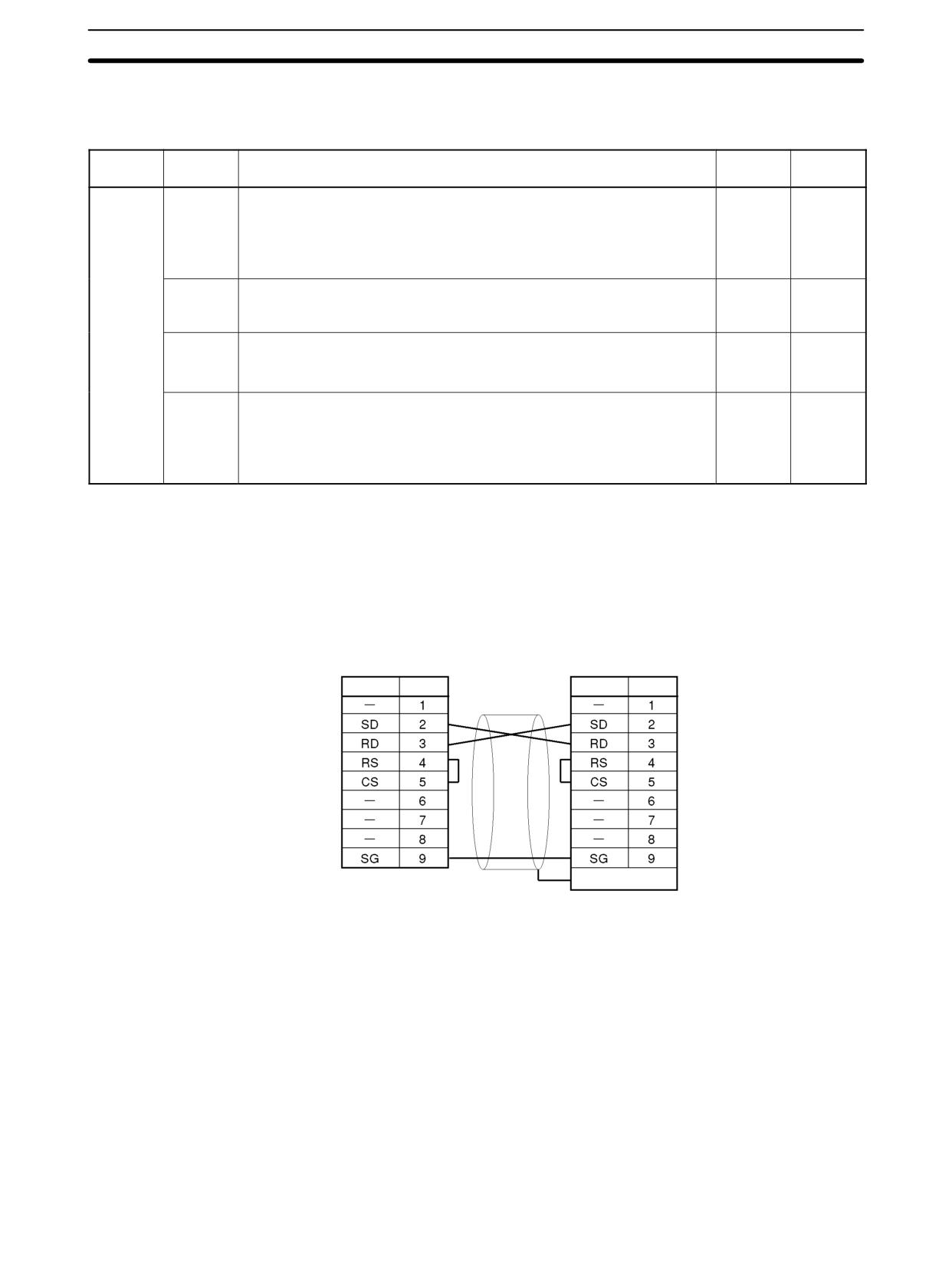
The RS-232C cable used for 1:1 PC Links is a cross connection cable. When
there is no CTS control on the RS-232C port, the connection is made as shown
in the following diagram. With the CPM2C, the CPM2C-CN111 and CS1W-
CN118 connecting cables are used.
RS-232C port
RS-232C port
Signal Pin No.
Signal Pin No.
Recommended cables
XW2Z-200T:
2m
XW2Z-500T:
5m
Hood
4-4
SRM1(-V2) Communications Functions
4-4-1
Host Link Communications
Host Link communications were developed by OMRON for the purpose of con-
necting PCs and one or more host computers by RS-232C cable, and controlling
PC communications from a host computer. Normally the host computer issues a
command to a PC, and the PC automatically sends back a response. Thus the
communications are carried out without the PCs being actively involved. The
PCs also have the ability to initiate data transmissions when direct involvement
is necessary.
In general, there are two means for implementing Host Link communications.
One is based on C-mode commands, and the other on FINS (CV-mode) com-
264
SRM1(-V2) Communications Functions
Section
4-4
mands. The SRM1(-V2) supports C-mode commands only. For details on Host
Link communications, refer to 4-5 Host Link Commands.
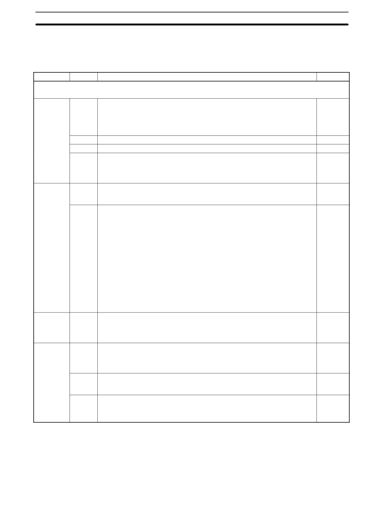
PC Setup Settings
The SRM1(-V2)’s peripheral port and RS-232C port settings must be set proper-
ly in order to use the Host Link communications, as shown in the following table.
Word
Bit
Function
Setting
Peripheral Port Settings
The following settings are effective after transfer to the PC.
DM 6650
00 to 03
Port settings
To match
0: Standard (1 start bit, 7-bit data, 2 stop bits, even parity, 9,600 bps)
host pa-
1: Settings in DM 6651
rameters
(Other settings will cause a non-fatal error, the default setting (0) will be used, and
AR 1302 will turn ON.)
04 to 07
Not used.
0
08 to 11
Not used.
0
12 to 15
Communications mode
0: Host
0: Host Link; 1: No-protocol
Link
(Other settings will cause a non-fatal error, the default setting (0) will be used, and
AR 1302 will turn ON.)
DM 6651
00 to 07
Baud rate
To match
00: 1.2K, 01: 2.4K, 02: 4.8K, 03: 9.6K, 04: 19.2K
host pa-
rameters
08 to 15
Frame format
To match
Start
Length
Stop
Parity
host pa-
00:
1 bit
7 bits
1 bit
Even
rameters
01:
1 bit
7 bits
1 bit
Odd
02:
1 bit
7 bits
1 bit
None
03:
1 bit
7 bits
2 bit
Even
04:
1 bit
7 bits
2 bit
Odd
05:
1 bit
7 bits
2 bit
None
06:
1 bit
8 bits
1 bit
Even
07:
1 bit
8 bits
1 bit
Odd
08:
1 bit
8 bits
1 bit
None
09:
1 bit
8 bits
2 bit
Even
10:
1 bit
8 bits
2 bit
Odd
11:
1 bit
8 bits
2 bit
None
(Other settings will cause a non-fatal error, the default setting (00) will be used, and
AR 1302 will turn ON.)
DM 6652
00 to 15
Transmission delay (Host Link)
To match
0000 to 9999 (BCD): Set in units of 10 ms.
host pa-
rameters
(Other settings will cause a non-fatal error, the default setting (0000) will be used,
and AR 1302 will turn ON.)
DM 6653
00 to 07
Node number (Host Link)
00 to 31
00 to 31 (BCD)
(Other settings will cause a non-fatal error, the default setting (0000) will be used,
and AR 1302 will turn ON.)
08 to 11
Start code enable (RS-232C, effective when bits 12 to 15 of DM 6650 are set to 1.)
Any
0: Disable
1: Set
12 to 15
End code enable (RS-232C, effective when bits 12 to 15 of DM 6650 are set to 1.)
Any
0: Disable (number of bytes received)
1: Set (specified end code)
2: CR, LF
265
SRM1(-V2) Communications Functions
Section
4-4
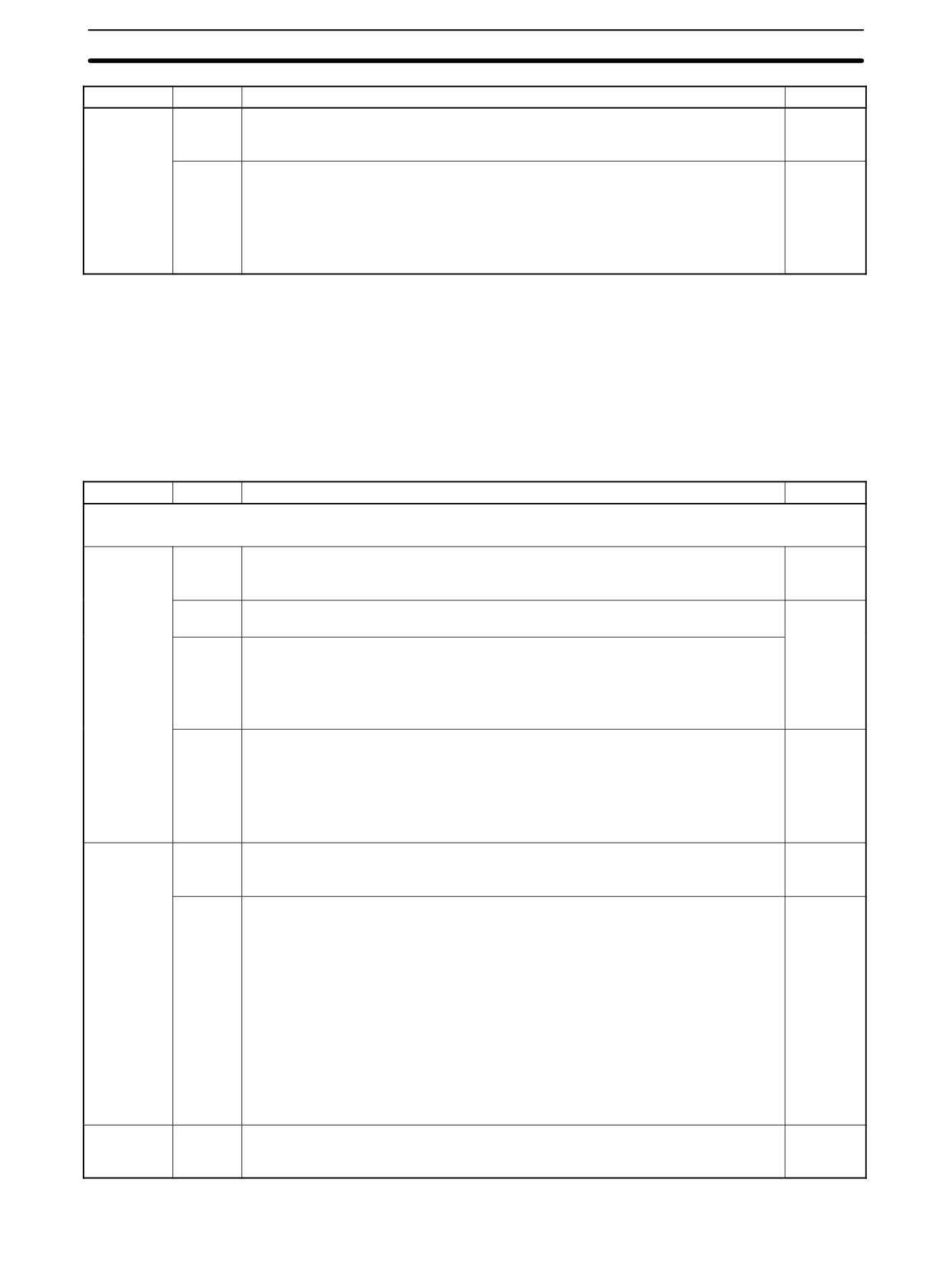
Word
Bit
Function
Setting
DM 6654
00 to 07
Start code (effective when bits 08 to 11 of DM6650 are set to 1.)
Any
00: 256 bytes
01 to FF: 1 to 255 bytes
08 to 15
End code (no-protocol)
Any
When bits 12 to 15 of DM6653 are set to 0:
00: 256 bytes
01 to FF: 1 to 255 bytes
When bits 12 to 15 of DM6653 are set to 1:
Setting: 00 to FF (Hex)
Note If an out-of-range value is set, the following communications conditions will re-
sult. In that case, reset the value so that it is within the permissible range.
Communications mode:
Host Link
Communications format: Standard settings
(1 start bit, 7-bit data; 2 stop bits, even parity,
9,600 bps)
Transmission delay:
No
Node number:
00
Word
Bit
Function
Setting
RS-232C Port Settings
The following settings are effective after transfer to the PC.
DM 6645
00 to 03
Port settings
To match
0: Standard (1 start bit, 7-bit data, 2 stop bits, even parity, 9,600 bps)
host pa-
1: Settings in DM 6646
rameters
04 to 07
CTS control settings
0
0: Disable; 1: Set
08 to 11
When using a 1:1 PC Link: Sets the link words for 1:1 PC Link.
0: LR 00 to LR 15
Not 0: Disable
When using a 1:N NT Link: Sets the maximum PT node number.
1 to 7
12 to 15
Communications mode
0
0: Host Link; 1: No-protocol; 2: 1:1 PC Link Slave; 3: 1:1 PC Link Master; 4: 1:1 NT
Link; 5: 1:N NT Link
(Any other setting specifies Host Link mode, causes a non-fatal error, and turns ON
AR 1302.)
The 1:N NT Link is supported by SRM1-C02-V2 only.
DM 6646
00 to 07
Baud rate
To match
00: 1.2K, 01: 2.4K, 02: 4.8K, 03: 9.6K, 04: 19.2K
host pa-
rameters
08 to 15
Frame format
To match
Start
Length
Stop
Parity
host pa-
00:
1 bit
7 bits
1 bit
Even
rameters
01:
1 bit
7 bits
1 bit
Odd
02:
1 bit
7 bits
1 bit
None
03:
1 bit
7 bits
2 bit
Even
04:
1 bit
7 bits
2 bit
Odd
05:
1 bit
7 bits
2 bit
None
06:
1 bit
8 bits
1 bit
Even
07:
1 bit
8 bits
1 bit
Odd
08:
1 bit
8 bits
1 bit
None
09:
1 bit
8 bits
2 bit
Even
10:
1 bit
8 bits
2 bit
Odd
11:
1 bit
8 bits
2 bit
None
DM 6647
00 to 15
Transmission delay (Host Link)
To match
0000 to 9999 (BCD): Set in units of 10 ms, e.g., setting of 0001 equals 10 ms
host pa-
rameters
266
SRM1(-V2) Communications Functions
Section
4-4
Word
Bit
Function
Setting
DM 6648
00 to 07
Node number (Host Link, effective when bits 12 to 15 of DM 6645 are set to 0.)
00 to 31
00 to 31 (BCD)
08 to 11
Start code enable (RS-232C, effective when bits 12 to 15 of DM 6645 are set to 1.)
Any
0: Disable; 1: Set
12 to 15
End code enable (RS-232C, effective when bits 12 to 15 of DM 6645 are set to 1.)
Any
0: Disable (number of bytes received)
1: Set (specified end code)
2: CR, LF
DM 6649
00 to 07
Start code (RS-232C)
Any
00: 256 bytes
01 to FF: 1 to 255 bytes
08 to 15
End code enable (RS-232C)
Any
00 to FF (BIN)
Note If an out-of-range value is set, the following communications conditions will re-
sult. In that case, reset the value so that it is within the permissible range.
Communications mode:
Host Link
Communications format:
Standard settings
(1 start bit, 7-bit data; 2 stop bits, even parity,
9,600 bps)
Transmission delay:
No
Node number:
00
Example Program
This example shows a BASIC program that reads the status of the SRM1(-V2)’s
inputs in IR 000. For more details, refer to 4-5 Host Link Commands.
An FCS (frame check sequence) check isn’t performed on the received re-
sponse data in this program. Be sure that the host computer’s RS-232C port is
configured correctly before executing the program.
1000 ’
1010 ’SRM1 Sample Program for BASIC
1020 ’
1050 ’
1060 ’
Set value RS-232C SPEED:9600BPS,PARITY:EVEN,DATA:7,STOP:2
1070 OPEN ”COM:E73” AS #1
1080 *REPEAT
1090 ’
Transmission data input
1100 INPUT ”send data:”,SEND$
1110 ’
FCS Calculation
1120 FCS=0
1130 FOR IFCS=1 TO LEN(SEND$)
1140 FCS=FCS XOR ASC(MID$(SEND$;IFCS,1)
1150 NEXT
1160 FCS$=RIGHT$(”0”+HEX$(FCS),2)
1170 ’
Communications execute
1180 ZZZ$=SEND$+FCS$+”*”+CHR$(13)
1190 PRINT #1,ZZZ$;
1200 ’
Response check
1210 RECCNT=0:TMP$=””
1220 *DRECLOOP
1230 IF LOC(1)<>0 THEN *DREC1
1240 RECCNT=RECCNT+1
1250 IF RECCNT=5000 THEN *DRECERR ELSE *DRECLOOP
1260 *DREC1
1270 TMP$=TMP$+INPUT$(LOC(1),#1)
1280 IF RIGHT$(TMP$,1)=CHR$(13) THEN *DRECEND ELSE RECCNT=0:GOTO *DRECLOOP
1290 *DRECERR
267
SRM1(-V2) Communications Functions
Section
4-4
1300 TMP$=”No response!!”+CHR$(13)
1310 *DRECEND
1320 RECV$=TMP$
1330 PRINT ”receive data:”;RECV$
1340 ’
Go to transmission data input
1350 GOTO *REPEAT
1360 ’
Processing complete
1370 CLOSE #1
1380 END
4-4-2
No-protocol Communications
This section explains no-protocol (RS-232C) communications. No-protocol
communications allow data to be exchanged with standard RS-232C devices
such as printers and bar code readers. Data can be printed out by a printer or
read by a bar code reader. Handshaking is not supported for no-protocol com-
munications.
Communications Procedure
Transmissions
1, 2, 3...
1. Check to see that AR 0805 (the RS-232C Port Transmit Ready Flag) has
turned ON.
2. Use the TXD(48) instruction to transmit the data.
(@)TXD(48)
S: Leading word no. of data to be transmitted
S
C: Control data
C
N: Number of bytes to be transmitted (4 digits BCD), 0000 to 0256
N
From the time this instruction is executed until the data transmission is complete,
AR 0805 ( or AR0813 for the peripheral port) will remain OFF. (It will turn ON
again upon completion of the data transmission.)
Start and end codes are not included when the number of bytes to be transmitted
is specified. The largest transmission that can be sent with or without start and
end codes in 256 bytes, N will be between 254 and 256 depending on the desig-
nations for start and end codes. If the number of bytes to be sent is set to 0000,
only the start and end codes will be sent.
256 bytes max.
Start code
Data
End code
To reset the RS-232C port (i.e., to restore the initial status), turn on SR 25209. To
reset the peripheral port, turn on SR 25208. These bits will turn OFF automati-
cally after the reset.
Receptions
1, 2, 3...
1. Confirm that AR 0806 (RS-232C Reception Complete Flag) or AR 0814 (Pe-
ripheral Reception Complete Flag) is ON.
268
SRM1(-V2) Communications Functions
Section
4-4
2. Use the RXD(47) instruction to receive the data.
(@)RXD(47)
D: Leading word no. for storing reception data
D
C: Control data
C
Bits 00 to 03
N
0: Leftmost bytes first
1: Rightmost bytes first
Bits 12 to 15
0: RS-232C port
1: Peripheral port
N: Number of bytes stored (4 digits BCD), 0000 to 0256
3. The results of reading the data received will be stored in the AR area. Check
to see that the operation was successfully completed. The contents of these
bits will be reset each time RXD(47) is executed.
RS-232C
Peripheral
Error
port
port
AR 0800 to
AR 0808 to
RS-232C port error code (1 digit BCD) 0: Normal
AR 0803
AR 0811
completion 1: Parity error 2: Framing error 3: Over-
run error
AR 0804
AR0812
Communications error
AR 0807
AR0815
Reception Overrun Flag (After reception was com-
pleted, the subsequent data was received before the
data was read by means of the RXD(47) instruction.)
AR 09
AR10
Number of bytes received
To reset the RS-232C port (i.e., to restore the initial status), turn ON SR 25209.
To reset the peripheral port, turn ON SR 25208. These bits will turn OFF auto-
matically after the reset.
The start code and end code are not included in AR 09 or AR 10 (number of bytes
received).
The data will be as follows: “31323132313231323132CR LF”
Peripheral Port Settings
When the peripheral port is used to conduct no-protocol communications, the
following settings must be made from the Programming Device to DM 6650 to
DM 6653 in the SRM1(-V2).
Word
Bit
Function
Setting
Peripheral Port Settings
The following settings are effective after transfer to the PC.
DM 6650
00 to 03
Port settings
As re-
0: Standard (1 start bit, 7-bit data, 2 stop bits, even parity, 9,600 bps)
quired
1: Settings in DM 6651
(Other settings will cause a non-fatal error, the default setting (0) will be used, and
AR 1302 will turn ON.)
04 to 07
Not used.
0
08 to 11
Not used.
0
12 to 15
Communications mode
1: No-pro-
0: Host Link; 1: No-protocol
tocol
(Other settings will cause a non-fatal error, the default setting (0) will be used, and
AR 1302 will turn ON.)
269
SRM1(-V2) Communications Functions
Section
4-4
Word
Bit
Function
Setting
DM 6651
00 to 07
Baud rate
As re-
00: 1.2K, 01: 2.4K, 02: 4.8K, 03: 9.6K, 04: 19.2K
quired
08 to 15
Frame format
As re-
Start
Length
Stop
Parity
quired
00:
1 bit
7 bits
1 bit
Even
01:
1 bit
7 bits
1 bit
Odd
02:
1 bit
7 bits
1 bit
None
03:
1 bit
7 bits
2 bit
Even
04:
1 bit
7 bits
2 bit
Odd
05:
1 bit
7 bits
2 bit
None
06:
1 bit
8 bits
1 bit
Even
07:
1 bit
8 bits
1 bit
Odd
08:
1 bit
8 bits
1 bit
None
09:
1 bit
8 bits
2 bit
Even
10:
1 bit
8 bits
2 bit
Odd
11:
1 bit
8 bits
2 bit
None
(Other settings will cause a non-fatal error, the default setting (00) will be used, and
AR 1302 will turn ON.)
DM 6652
00 to 15
Transmission delay (Host Link)
To match
0000 to 9999 (BCD): Set in units of 10 ms.
host pa-
rameters
(Other settings will cause a non-fatal error, the default setting (0000) will be used,
and AR 1302 will turn ON.)
DM 6653
00 to 07
Node number (Host Link)
00 to 31
00 to 31 (BCD)
(Other settings will cause a non-fatal error, the default setting (0000) will be used,
and AR 1302 will turn ON.)
08 to 11
Start code enable (RS-232C, effective when bits 12 to 15 of DM 6650 are set to 1.)
As re-
0: Disable
quired
1: Set
12 to 15
End code enable (RS-232C, effective when bits 12 to 15 of DM 6650 are set to 1.)
As re-
0: Disable (number of bytes received)
quired
1: Set (specified end code)
2: CR, LF
DM 6654
00 to 07
Start code (effective when bits 08 to 11 of DM6650 are set to 1.)
As re-
00: 256 bytes
quired
01 to FF: 1 to 255 bytes
08 to 15
End code (no-protocol)
As re-
quired
When bits 12 to 15 of DM6653 are set to 0:
00: 256 bytes
01 to FF: 1 to 255 bytes
When bits 12 to 15 of DM6653 are set to 1:
Setting: 00 to FF (Hex)
Note If an out-of-range value is set, the following communications conditions will re-
sult. In that case, reset the value so that it is within the permissible range.
Communications mode:
Host Link
Communications format: Standard settings
(1 start bit, 7-bit data; 2 stop bits, even parity,
9,600 bps)
Transmission delay:
No
Node number:
00
RS-232C Port Settings
When the RS-232C port is used to conduct no-protocol communications, the fol-
lowing settings must be made from the Programming Device to DM 6645 to
DM 6649 in the SRM1(-V2).
270
SRM1(-V2) Communications Functions
Section
4-4
Word
Bit
Function
Setting
RS-232C Port Settings
The following settings are effective after transfer to the PC.
DM 6645
00 to 03
Port settings
As re-
0: Standard (1 start bit, 7-bit data, 2 stop bits, even parity, 9,600 bps)
quired
1: Settings in DM 6646
04 to 07
CTS control settings
0: Disable; 1: Set
08 to 11
When using a 1:1 PC link: Sets the link words for 1:1 PC Link.
0
0: LR 00 to LR 15
Not 0: Disable
When using a 1:N NT Link: Sets the maximum PT node number.
1 to 7
The 1:N NT Link is supported by SRM1-C02-V2 only.
12 to 15
Communications mode
1
0: Host Link; 1: No-protocol; 2: 1:1 PC Link Slave; 3: 1:1 PC Link Master; 4: 1:1 NT
Link; 5: 1:N NT Link
(Any other setting specifies Host Link mode, causes a non-fatal error, and turns ON
AR 1302.)
The 1:N NT Link is supported by SRM1-C02-V2 only.
DM 6646
00 to 07
Baud rate
As re-
00: 1.2K, 01: 2.4K, 02: 4.8K, 03: 9.6K, 04: 19.2K
quired
08 to 15
Frame format
As re-
Start
Length
Stop
Parity
quired
00:
1 bit
7 bits
1 bit
Even
01:
1 bit
7 bits
1 bit
Odd
02:
1 bit
7 bits
1 bit
None
03:
1 bit
7 bits
2 bit
Even
04:
1 bit
7 bits
2 bit
Odd
05:
1 bit
7 bits
2 bit
None
06:
1 bit
8 bits
1 bit
Even
07:
1 bit
8 bits
1 bit
Odd
08:
1 bit
8 bits
1 bit
None
09:
1 bit
8 bits
2 bit
Even
10:
1 bit
8 bits
2 bit
Odd
11:
1 bit
8 bits
2 bit
None
DM 6647
00 to 15
Transmission delay (Host Link)
As re-
0000 to 9999 (BCD): Set in units of 10 ms, e.g., setting of 0001 equals 10 ms
quired
DM 6648
00 to 07
Node number (Host Link, effective when bits 12 to 15 of DM 6645 are set to 0.)
As re-
00 to 31 (BCD)
quired
08 to 11
Start code enable (RS-232C, effective when bits 12 to 15 of DM 6645 are set to 1.)
As re-
0: Disable; 1: Set
quired
12 to 15
End code enable (RS-232C, effective when bits 12 to 15 of DM 6645 are set to 1.)
0: Disable (number of bytes received)
1: Set (specified end code)
2: CR, LF
DM 6649
00 to 07
Start code (RS-232C)
00: 256 bytes
01 to FF: 1 to 255 bytes
08 to 15
End code enable (RS-232C)
00 to FF (BIN)
Note If an out-of-range value is set, the following communications conditions will re-
sult. In that case, reset the value so that it is within the permissible range.
Communications mode:
Host Link
Communications format:
Standard settings
(1 start bit, 7-bit data; 2 stop bits, even parity,
9,600 bps)
Transmission delay:
No
271
SRM1(-V2) Communications Functions
Section
4-4
Node number:
00
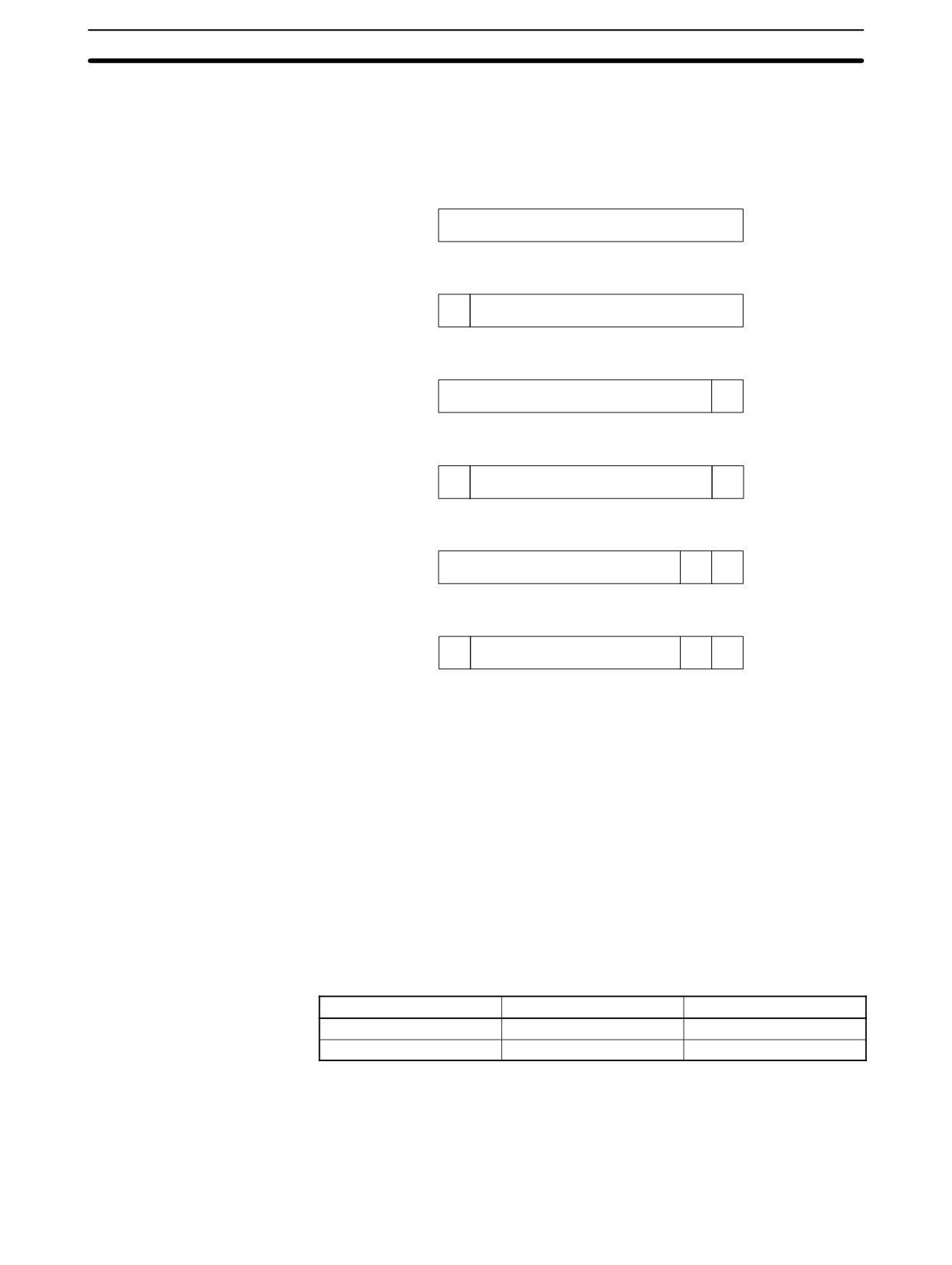
Transmission Data
When no-protocol communications are used, TXD(48) is used to send data and
Configuration
RXD(47) to receive data. The maximum amount of data that can be either sent or
received is 259 bytes, including the start/end code.
• No Start or End Code:
Data (256 bytes max.)
• Only a Start Code:
ST
Data (256 bytes max.)
• Only an End Code:
Data (256 bytes max.)
ED
• Both an Start and End Code:
ST
Data (256 bytes max.)
ED
• End Code of CR, LF:
Data (256 bytes max.)
CR
LF
• Start Code 00-FF/End Code CR,LF:
ST
Data (256 bytes max.)
CR
LF
Note
1. The start and end codes are set in DM 6648 to DM 6649 and DM 6653 to
DM 6654 of the PC Setup.
2. When there are several start and end codes, the first part of each will be ef-
fective.
3. When the end code duplicates the transmission data and the transmission is
stopped part way through, use CR or LF as the end code.
4. The start and end codes are not stored.
When sending data from the SRM1(-V2), check that the Transmission Enable
Flag is ON for executing the TXD(48) instruction. The Transmission Enable Flag
will turn OFF while the data is being transmitted and will turn ON again when
transmission is complete.
Transmission Flags
After the SRM1(-V2) has received data, the Receive Enable Flag turns ON.
When the RXD instruction is executed, the data received will be written to the
specified words and the Reception Complete Flag will turn OFF.
Flag
Peripheral port
RS-232C port
Transmission Enable Flag
AR 0813
AR 0805
Reception Complete Flag
AR 0814
AR 0806
Note
The timing from data reception starting to completion for the SRM1(-V2) is as
indicated below.
Reception Start:
Without start code:
Normal reception status
With start code:
After start code is received.
272
SRM1(-V2) Communications Functions
Section
4-4
Reception Complete:
When either the end code, the specified no. of bytes, or 256 bytes are received.
Program Example
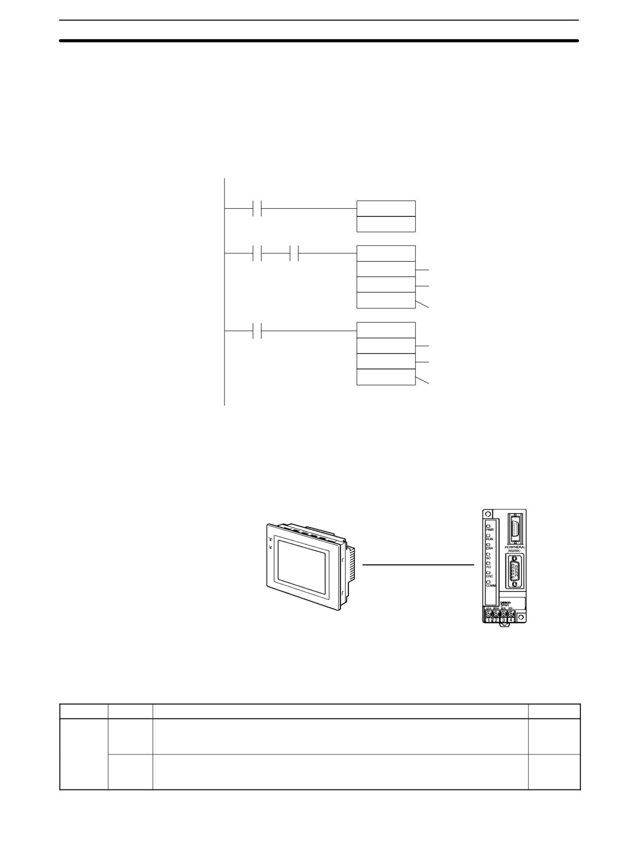
The following program example is for no-protocol communication conducted
through a RS-232C port using TXD(48) and RXD(47) instructions.
If AR 0805 (Transmission Enable Flag) is ON when 00100 is ON, then data from
DM0100 to DM0104 is transmitted from higher to lower values. When AR 0806
(Reception Enable Flag) turns ON, 256 bytes of received data are read and writ-
ten to DM 0200 from higher to lower values.
00100
DIFU(13)
No-protocol communications start
00101
00100
AR0805
@TXD
DM0100
First word holding send data.
#0000
Using the RS-232C port data is
stored from higher to lower values
#0010
10 bytes transmitted
AR0806
@RXD
DM0200
First word to store receive data.
#0000
Using the RS-232C port data is
stored from higher to lower values
256
256 bytes transmitted
4-4-3
One-to-one NT Link Communications
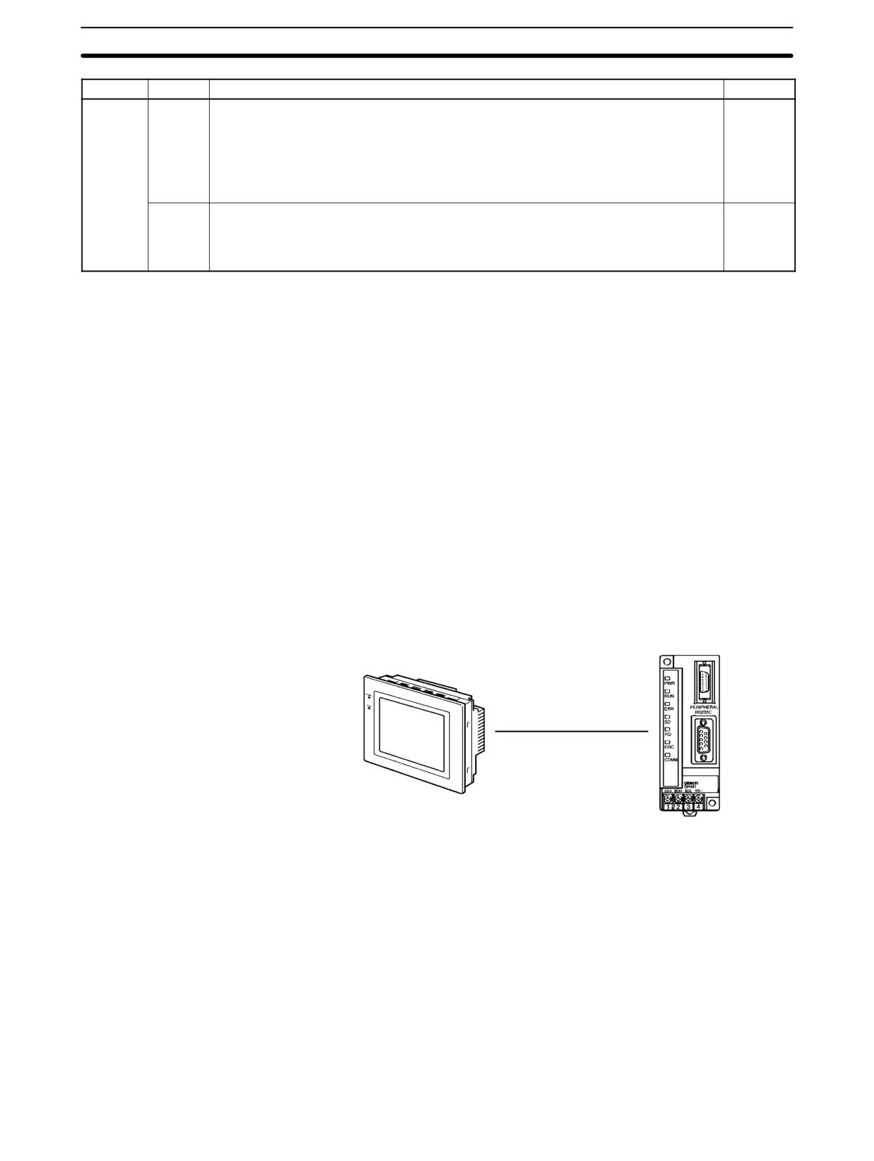
Using the 1:1 NT Link, the SRM1(-V2) PC can be connected to the Program-
mable Terminal (NT Link Interface.) The RS-232C port can be used for the 1:1
NT Link.
SRM1
OMRON Programmable Terminal
The 1:1 NT Link is possible only with the SRM1-C02-V1/-V2 PCs, which have an
RS-232C port.
PC Setup Settings
The settings relating to 1:1 NT Link PC communications must be set as shown in
the following table.
Word
Bit
Function
Setting
DM 6645
00 to 03
Port settings1
00 or 01
00: Standard (1 start bit, 7-bit data, 2 stop bits, even parity, 9,600 bps)
01: Settings in DM 6646
04 to 07
CTS control settings
0 or 1
0: Disable
1: Set
273
SRM1(-V2) Communications Functions
Section
4-4
Word
Bit
Function
Setting
08 to 11
When using a 1:1 PC Link: Sets the link words for 1:1 PC Link.
Any
0: LR 00 to LR 15
Not 0: Disable
When using a 1:N NT Link: Sets the maximum PT node number.
1 to 7
The 1:N NT Link is supported by SRM1-C02-V2 only.
12 to 15
Communications mode1
4
0: Host Link; 1: No-protocol; 2: 1:1 PC Link Slave; 3: 1:1 PC Link Master; 4: 1:1 NT
Link; 5: 1:N NT Link
The 1:N NT Link is supported by SRM1-C02-V2 only.
Note
1. If an improper setting is used, a non-fatal error will occur, AR 1302 will be
turned ON, and the default setting (0 or 00) will be used.
2. For information on the NT Link settings for another OMRON PC, refer to that
PC’s Operation Manual.
3. If an out-of-range value is set, the following communications conditions will
result. In that case, reset the value so that it is within the permissible range.
Communications mode:
Host Link
Communications format:
Standard settings
(1 start bit, 7-bit data; 2 stop bits, even parity,
9,600 bps)
Transmission delay:
No
Node number:
00
4-4-4
One-to-N NT Link Communications
The 1:N NT Link allows an SRM1(-V2) PC to be connected to as many as 8 OM-
RON Programmable Terminals (PTs) and direct access provides high-speed
communications. The 1:N NT Link can be used with the RS-232C port.
SRM1
OMRON Programmable Terminal
The 1:N NT Link is possible only with the SRM1-C02-V2 PCs, which have an
RS-232C port.
274
SRM1(-V2) Communications Functions
Section
4-4
Cable Connections
Refer to the SRM1 Master Control Units Operation Manual for information on
cable connections in a 1:N NT Link.
PC Setup Settings
When the RS-232C port is used for a 1:N NT Link, make the following PC Setup
settings from a Programming Device.
Word
Bit
Function
Setting
DM 6645
00 to 03
Port settings1
00 or 01
00: Standard (1 start bit, 7-bit data, 2 stop bits, even parity, 9,600 bps)
01: Settings in DM 6646
04 to 07
CTS control settings
0 or 1
0: Disable
1: Set
08 to 11
When using a 1:1 PC link: Sets the link words for 1:1 PC Link.
1 to 7
0: LR 00 to LR 15
Not 0: Disable
When using a 1:N NT Link: Sets the maximum PT node number.
1 to 7
The 1:N NT Link is supported by SRM1-C02-V2 only.
12 to 15
Communications mode1
5
0: Host Link; 1: No-protocol; 2: 1:1 PC Link Slave; 3: 1:1 PC Link Master; 4: 1:1 NT
Link; 5: 1:N NT Link
The 1:N NT Link is supported by SRM1-C02-V2 only.
Note
1. If an improper setting is used, a non-fatal error will occur, AR 1302 will be
turned ON, and the default setting (0 or 00) will be used.
2. For information on 1:N NT Link settings for OMRON PTs, refer to the PT’s
Operation Manual.
3. If an out-of-range value is set, the following communications conditions will
result. In that case, reset the value so that it is within the permissible range.
Communications mode:
Host Link
Communications format: Standard settings
(1 start bit, 7-bit data; 2 stop bits, even parity,
9,600 bps)
Transmission delay:
No
Node number:
00
4-4-5
One-to-one PC Link Communications
In a 1:1 PC Link, an SRM1 is linked to another SRM1, CPM1, CPM1A, CPM2A,
CPM2C, CQM1, C200HS, or C200HX/HG/HE PC through a standard RS-232C
cable. One of the PCs will serve as the master and the other as the slave. The 1:1
PC Link can connect up to 256 bits (LR 0000 to LR 1515) in the two PCs.
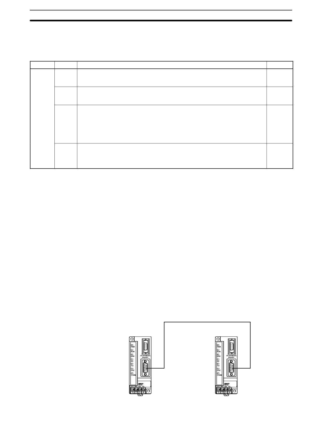
One-to-one SRM1(-V2)
The following diagram shows a 1:1 PC Link between two SRM1(-V2)s.
PC Links
SRM1
SRM1
RS-232C Port
RS-232C Port
275
SRM1(-V2) Communications Functions
Section
4-4
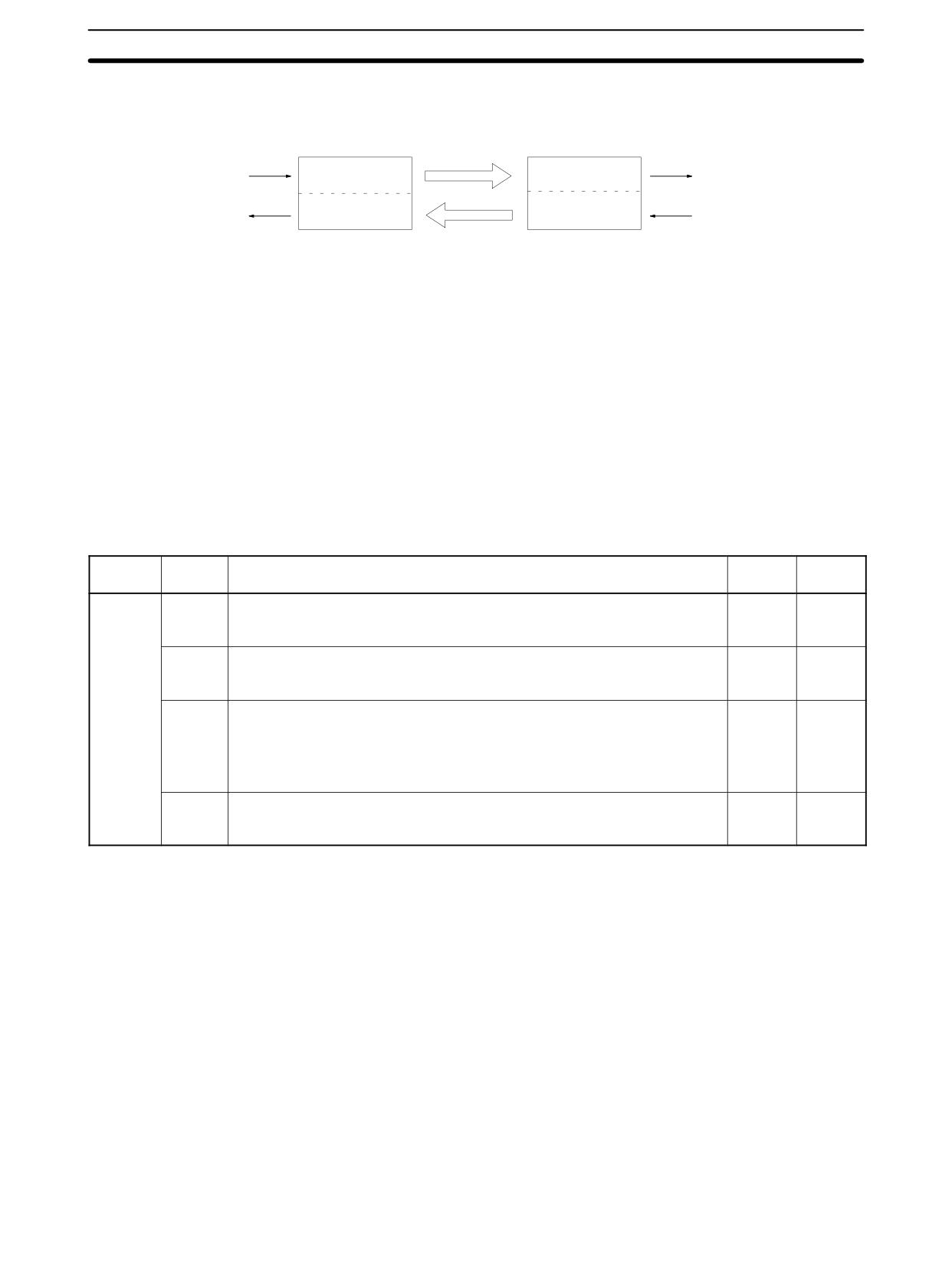
The words used for the 1:1 PC Link are as shown below.
Master
Slave
LR00
LR00
Write data
Area for writing
Area for reading
Read data
LR07
LR07
LR08
LR08
Read data
Area for reading
Area for writing
Write data
LR15
LR15
Limitations of 1:1 PC Links
A 1:1 PC Link is possible only with the SRM1-C02-V1/V2 PCs, which are
with a SRM1(-V2)
equipped with an RS-232C port.
Only the 16 LR words from LR 00 to LR 15 can be linked in the SRM1, so use only
those 16 words in the CQM1 or C200HS when making a 1:1 PC Link with one of
those PCs. A 1:1 PC Link cannot be made to an SRM1 PC using LR 16 through
LR 63 in the CQM1 or C200HS.
Cable Connections
Refer to the SRM1 Master Control Units Operation Manual for information on
cable connections in a 1:1 PC Link.
PC Setup Settings
When an SRM1(-V2) is used in a 1:1 PC Link, make the following PC Setup set-
tings from a Programming Device.
Word
Bit
Function
Setting
Setting
(Master)
(Slave)
DM 6645
00 to 03
Port settings1
00 or 01
00 or 01
00: Standard (1 start bit, 7-bit data, 2 stop bits, even parity, 9,600 bps)
01: Settings in DM 6651
04 to 07
CTS Control settings
0
0
0: Disable
1: Set
08 to 11
When using a 1:1 PC Link: Sets the link words for 1:1 PC Link.
0
0
0: LR 00 to LR 15
Not 0: Disable
When using a 1:N NT Link: Sets the maximum PT node number.
1 to 7
12 to 15
Communications mode1
3
2
0: Host Link; 1: No-protocol; 2: 1:1 PC Link Slave; 3: 1:1 PC Link Master; 4:
1:1 NT Link; 5: 1:N NT Link
Note
1. If an improper setting is used, a non-fatal error will occur, AR 1302 will be
turned ON, and the default setting (0 or 00) will be used.
2. For information on the 1:1 PC Link settings for another OMRON PC, refer to
that PC’s Operation Manual.
3. If an out-of-range value is set, the following communications conditions will
result. In that case, reset the value so that it is within the permissible range.
Communications mode:
Host Link
Communications format: Standard settings
(1 start bit, 7-bit data; 2 stop bits, even parity,
9,600 bps)
Transmission delay:
No
Node number:
00
276
Host Link Commands
Section
4-5
Example Program
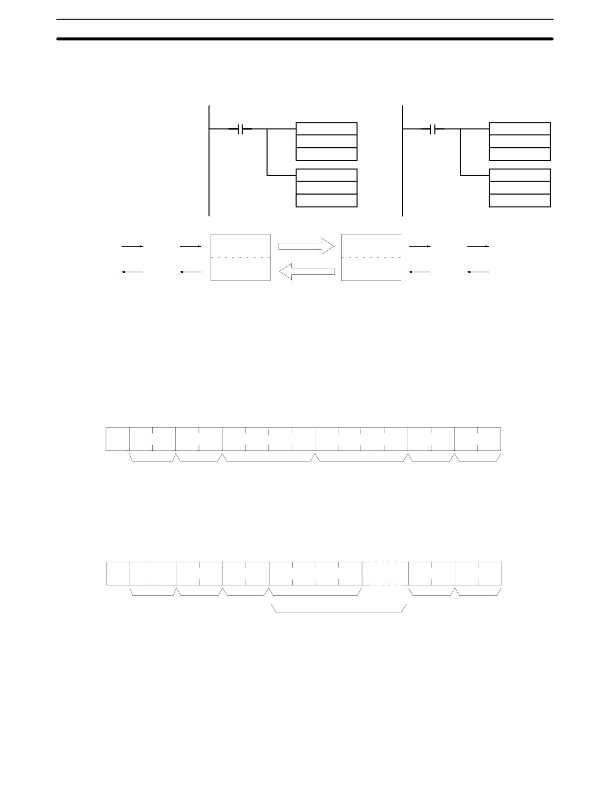
This example shows ladder programs that copy the status of IR 000 in each
SRM1 to IR 200 in the other SRM1.
Program in the Master
Program in the Slave
25313 (Always ON)
25313 (Always ON)
MOV(21)
MOV(21)
000
000
LR00
LR08
MOV(21)
MOV(21)
LR08
LR00
200
200
LR00
LR00
IR 000
Write
Writing area
Reading area
Read
IR 200
LR07
LR07
LR08
LR08
IR 200
Read
Reading area
Writing area
Write
IR 000
LR15
LR15
4-5
Host Link Commands
This section explains the commands that can be issued from the host computer
to the PC.
4-5-1
IR/SR AREA READ - RR
Reads the contents of the specified number of IR and SR words, starting from
the specified word.
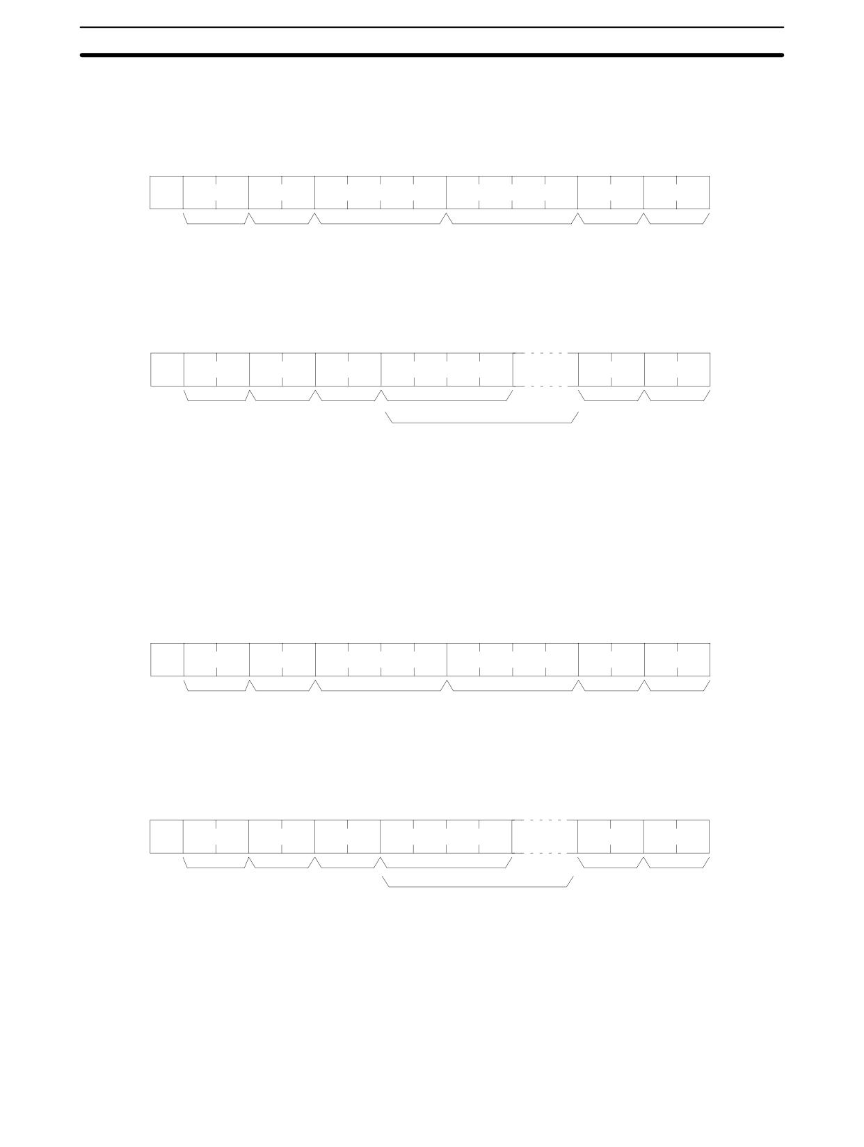
Command Format
@
x 101 x 100
R
R
x 103 x 102
x 101 x 100
x 103 x 102 x 101 x 100
:
↵
Node no.
Header
Beginning word*
No. of words
FCS
Terminator
code
(0000 to 0256)
Note *Beginning word: 0000 to 0049 and 0200 to 0255 in CPM2A/CPM2C PCs, 0000
to 0019 and 0200 to 0255 in CPM1/CPM1A/SRM1(-V2) PCs.
(A response of “0000” will be returned for non-existent IR and SR words.)
Response Format
An end code of 00 indicates normal completion.
@
x 101 x 100
R
R
x 161 x 160
x 163 x 162 x 161 x 160
:
↵
Node no.
Header
End code
Read data (1 word)
FCS
Terminator
code
Read data (for number of words read)
Note
1. Words 0050 to 0199 cannot be specified in CPM2A/CPM2C PCs and words
0020 to 0199 cannot be specified in CPM1/CPM1A/SRM1(-V2) PCs. If an
attempt to read any of these words is made, a response of 0000 will be re-
turned.
2. The response will be divided when reading more than 30 words of data.
Parameters
Read Data (Response)
The contents of the number of words specified by the command are returned in
hexadecimal as a response. The words are returned in order, starting with the
specified beginning word.
277
Host Link Commands
Section
4-5
4-5-2
LR AREA READ - RL
Reads the contents of the specified number of LR words, starting from the speci-
fied word.
Command Format
@
x 101 x 100
R
L
x 103 x 102
x 101 x 100
x 103 x 102 x 101 x 100
:
↵
Node no.
Header
Beginning word1
No. of words2
FCS
Terminator
code
Note
1. Beginning word: 0000 to 0015
2. No. of words: 0001 to 0016
Response Format
An end code of 00 indicates normal completion.
@
x 10
1 x 100
R
L
x 161 x 160
x 163 x 162 x 161 x 160
:
↵
Node no.
Header
End code
Read data (1 word)
FCS
Terminator
code
Read data (for number of words read)
Parameters
Read Data (Response)
The contents of the number of words specified by the command are returned in
hexadecimal as a response. The words are returned in order, starting with the
specified beginning word.
4-5-3
HR AREA READ - RH
Reads the contents of the specified number of HR words, starting from the speci-
fied word.
Command Format
@
x 101 x 100
R
H
x 103 x 102
x 101 x 100
x 103 x 102 x 101 x 100
:
↵
Node no.
Header
Beginning word1
No. of words2
FCS
Terminator
code
Note
1. Beginning word: 0000 to 0019
2. No. of words: 0001 to 0020
Response Format
An end code of 00 indicates normal completion.
@
x 10
1 x 100
R
H
x 161 x 160
x 163 x 162 x 161 x 160
:
↵
Node no.
Header
End code
Read data (1 word)
FCS
Terminator
code
Read data (for number of words read)
Parameters
Read Data (Response)
The contents of the number of words specified by the command are returned in
hexadecimal as a response. The words are returned in order, starting with the
specified beginning word.
4-5-4
PV READ - RC
Reads the contents of the specified number of timer/counter PVs (present val-
ues), starting from the specified timer/counter.
278
Host Link Commands
Section
4-5
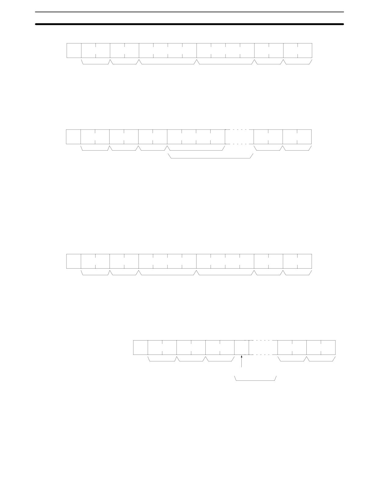
Command Format
@
x 101 x 100
R
C
x 103 x 102
x 101 x 100
x 103 x 102 x 101 x 100
:
↵
Node no.
Header
Beginning timer/counter1
No. of timers/counters
2
FCS
Terminator
code
Note
1. Beginning T/C: 0000 to 0255 in CPM2A/CPM2C PCs, 0000 to 0127 in
CPM1/CPM1A/SRM1(-V2) PCs
2. No. of T/Cs:
0001 to 0256 in CPM2A/CPM2C PCs, 0001 to 0128 in
CPM1/CPM1A/SRM1(-V2) PCs
Response Format
An end code of 00 indicates normal completion.
@
x 10
1 x 100
R
C
x 161 x 160
x 103 x 102 x 101 x 100
:
↵
Node no.
Header
End code
Read data (1 word)
FCS
Terminator
code
Read data (for number of words read)
The response will be divided when reading more than 30 words of data.
Parameters
Read Data (Response)
The number of present values specified by the command is returned in hexade-
cimal as a response. The PVs are returned in order, starting with the specified
beginning timer/counter.
4-5-5
TC STATUS READ - RG
Reads the status of the Completion Flags of the specified number of timers/
counters, starting from the specified timer/counter.
Command Format
@
x 101 x 100
R
G
x 103 x 102
x 101 x 100
x 103 x 102 x 101 x 100
:
↵
Node no.
Header
Beginning timer/counter1 No. of timers/counters2
FCS
Terminator
code
Note
1. Beginning T/C: 0000 to 0255 in CPM2A/CPM2C PCs, 0000 to 0127 in
CPM1/CPM1A/SRM1(-V2) PCs
2. No. of T/Cs:
0001 to 0256 in CPM2A/CPM2C PCs, 0001 to 0128 in
CPM1/CPM1A/SRM1(-V2) PCs
Response Format
An end code of 00 indicates normal completion.
ON/
@
x 10
1 x 100
R
G
x 161 x 160
:
↵
OFF
Node no.
Header
End code
FCS
Terminator
code
Read data
(1 timer/counter)
Read data
(for number of TC read)
The response will be divided when reading the status of more than 123 timer/
counters.
Parameters
Read Data (Response)
The status of the number of Completion Flags specified by the command is re-
turned as a response. “1” indicates that the Completion Flag is ON.
4-5-6
DM AREA READ - RD
Reads the contents of the specified number of DM words, starting from the spe-
cified word.
279
Host Link Commands
Section
4-5
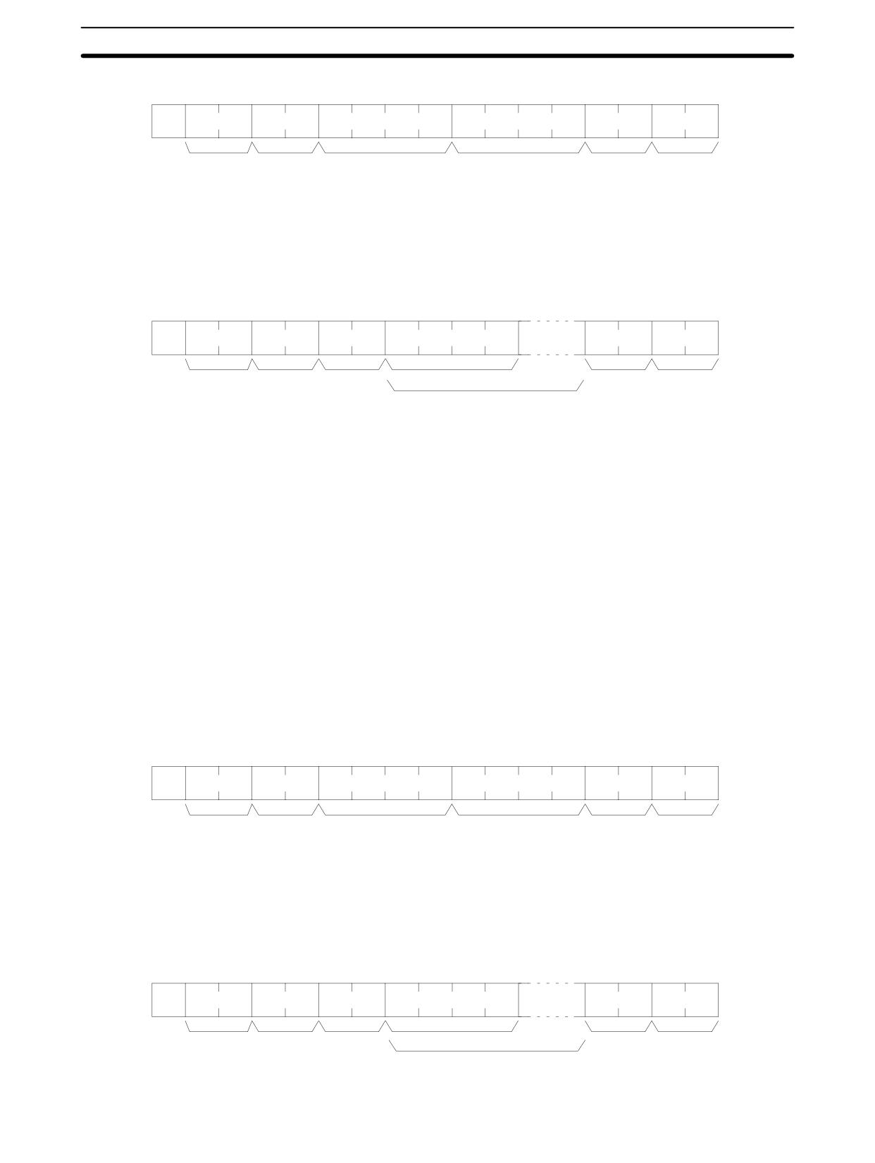
Command Format
@
x 101 x 100
R
D
x 103 x 102
x 101 x 100
x 103 x 102 x 101 x 100
:
↵
Node no.
Header
Beginning word*
No. of words
FCS
Terminator
code
(0001 to 6656)
Note Beginning word:
DM 0000 to DM 1023 and DM 6144 to DM 6655 in CPM1/CPM1A PCs
DM 0000 to DM 2047 and DM 6144 to DM 6655 in CPM2A/CPM2C/SRM1(-V2)
PCs. (A response of “0000” will be returned for non-existent DM words.)
Response Format
An end code of 00 indicates normal completion.
@
x 10
1 x 100
R
D
x 161 x 160
x 163 x 162 x 161 x 160
:
↵
Node no.
Header
End code
Read data (1 word)
FCS
Terminator
code
Read data (for number of words read)
Note
1. Words DM 1024 to DM 6143 in CPM1/CPM1A PCs and words DM 2048 to
DM 6143 in CPM2A/CPM2C/SRM1(-V2) PCs cannot be specified. If an at-
tempt to read any of these words is made, a response of 0000 will be re-
turned.
2. The response will be divided when reading more than 30 words of data.
Parameters
Read Data (Response)
The contents of the number of words specified by the command are returned in
hexadecimal as a response. The words are returned in order, starting with the
specified beginning word.
Note Be careful about the configuration of the DM area, as it varies depending on the
CPU Unit model.
4-5-7
AR AREA READ - RJ
Reads the contents of the specified number of AR words, starting from the speci-
fied word.
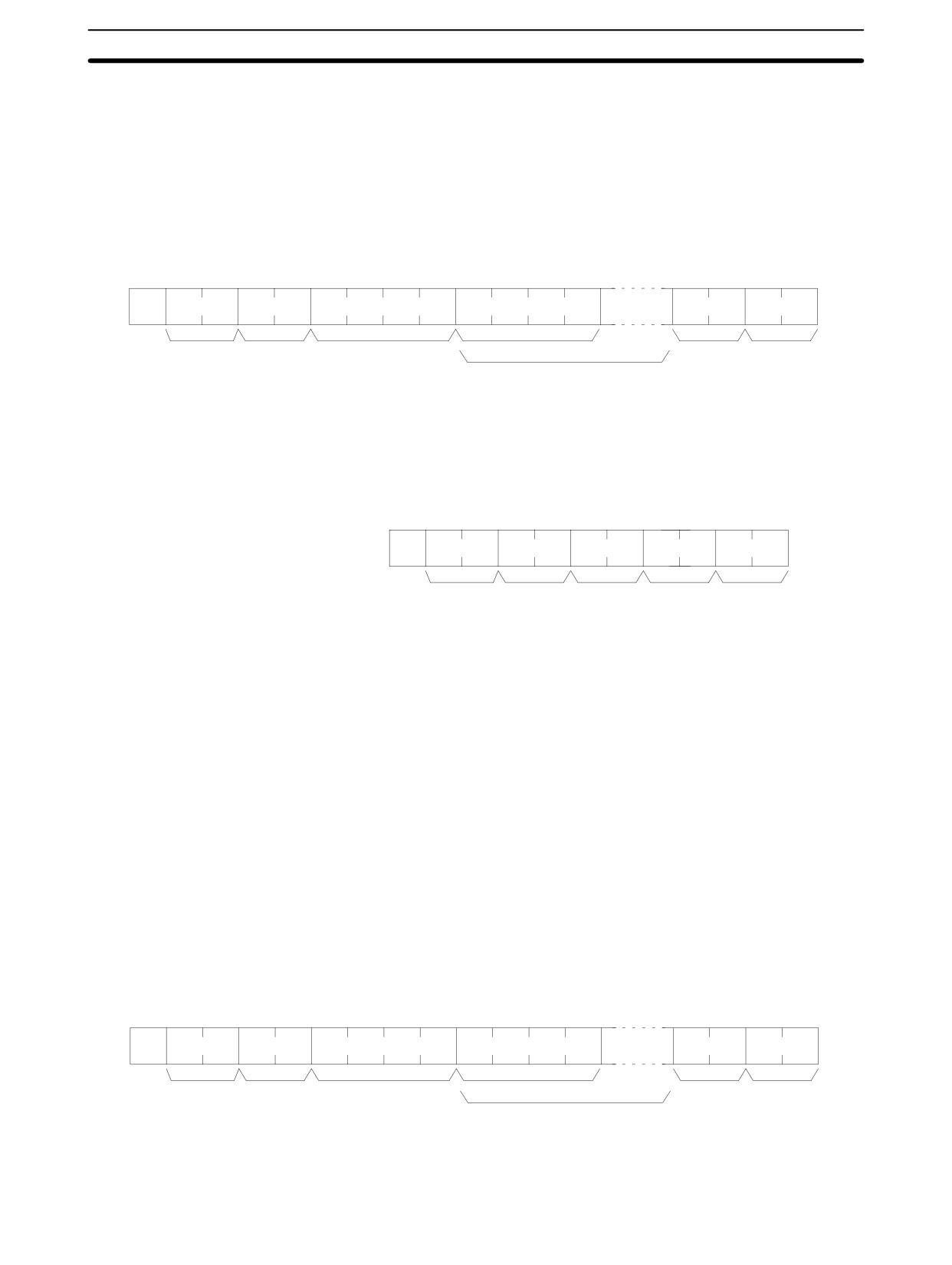
Command Format
@
x 101 x 100
R
J
x 103 x 102
x 101 x 100
x 103 x 102 x 101 x 100
:
↵
Node no.
Header
Beginning word
1
No. of words2
FCS
Terminator
code
Note
1. Beginning word: 0000 to 0023 in CPM2A/CPM2C PCs, 0000 to 0015 in
CPM1/CPM1A/SRM1(-V2) PCs
2. No. of words: 0001 to 0024 in CPM2A/CPM2C PCs, 0001 to 0016 in
CPM1/CPM1A/SRM1(-V2) PCs
Response Format
An end code of 00 indicates normal completion.
@
x 101 x 100
R
J
x 161 x 160
x 163 x 162 x 161 x 160
:
↵
Node no.
Header
End code
Read data (1 word )
FCS
Terminator
code
Read data
(for number of words read)
280
Host Link Commands
Section
4-5
Parameters
Read Data (Response)
The contents of the number of words specified by the command are returned in
hexadecimal as a response. The words are returned in order, starting with the
specified beginning word.
4-5-8
IR/SR AREA WRITE - WR
Writes data to the IR and SR areas, starting from the specified word. Writing is
done word by word.
Command Format
@
x 101 x 100
W
R
x 103 x 102
x 101 x 100
x 163 x 162 x 161 x 160
:
↵
Node no.
Header
Beginning word*
Write data (1 word)
FCS
Terminator
code
Write data
(for number of words to write)
Note
1. Beginning word: 0000 to 0049 and 0200 to 0252 in CPM2A/CPM2C PCs,
0000 to 0019 and 0200 to 0252 in CPM1/CPM1A/SRM1(-V2) PCs.
2. Divide the command when writing more than 30 words of data.
Response Format
An end code of 00 indicates normal completion.
@
x 10
1 x 100
W
R
x 161 x 160
:
↵
Node no.
Header
End code
FCS
Terminator
code
Note
Words 0050 to 0199 cannot be specified in CPM2A/CPM2C PCs and words
0020 to 0199 cannot be specified in CPM1/CPM1A/SRM1(-V2) PCs. If an at-
tempt is made to write to any of these words, the writing operation will not be
executed and normal completion occurs.
Parameters
Write Data (Command)
Specify in order the contents of the number of words to be written to the IR or SR
area in hexadecimal, starting with the specified beginning word.
Note
If data is specified for writing which exceeds the allowable range, an error will be
generated and the writing operation will not be executed. If, for example, 252 is
specified as the beginning word for writing,and two words of data are specified,
then 253 will become the last word for writing data, and the command will not be
executed because SR 253 is beyond the writable range.
4-5-9
LR AREA WRITE - WL
Writes data to the LR area, starting from the specified word. Writing is done word
by word.
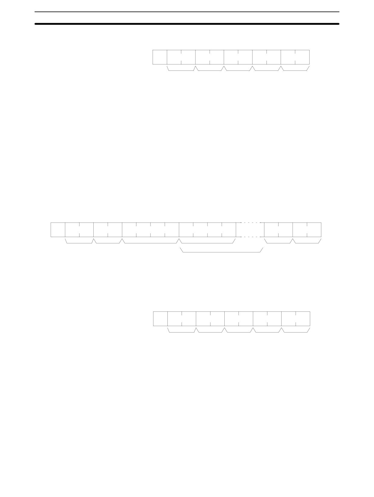
Command Format
@
x 101 x 100
W
L
x 103 x 102
x 101 x 100
x 163 x 162 x 161 x 160
:
↵
Node no.
Header
Beginning word*
Write data (1 word)
FCS
Terminator
code
Write data
(for number of words to write )
Note Beginning word: 0000 to 0015
281
Host Link Commands
Section
4-5
Response Format
An end code of 00 indicates normal completion.
@
x 10
1 x 100
W
L
x 161 x 160
:
↵
Node no.
Header
End code
FCS
Terminator
code
Parameters
Write Data (Command)
Specify in order the contents of the number of words to be written to the LR area
in hexadecimal, starting with the specified beginning word.
Note If data is specified for writing which exceeds the allowable range, an error will be
generated and the writing operation will not be executed. If, for example, 12 is
specified as the beginning word for writing and five words of data are specified,
then 16 will become the last word for writing data, and the command will not be
executed because LR 16 is beyond area boundary.
4-5-10 HR AREA WRITE - WH
Writes data to the HR area, starting from the specified word. Writing is done word
by word.
Command Format
@
x 101 x 100
W
H
x 103 x 102
x 101 x 100
x 163 x 162 x 161 x 160
:
↵
Node no.
Header
Beginning word*
Write data (1 word)
FCS
Terminator
code
Write data
(for no. of words to write)
Note
Beginning word:0000 to 0019
Response Format
An end code of 00 indicates normal completion.
@
x 10
1 x 100
W
H
x 161 x 160
:
↵
Node no.
Header
End code
FCS
Terminator
code
Parameters
Write Data (Command)
Specify in order the contents of the number of words to be written to the HR area
in hexadecimal, starting with the specified beginning word.
Note
If data is specified for writing which exceeds the allowable range, an error will be
generated and the writing operation will not be executed. If, for example, 18 is
specified as the beginning word for writing, and three words of data are speci-
fied, then 20 will become the last word for writing data, and the command will not
be executed because HR 20 is beyond area boundary.
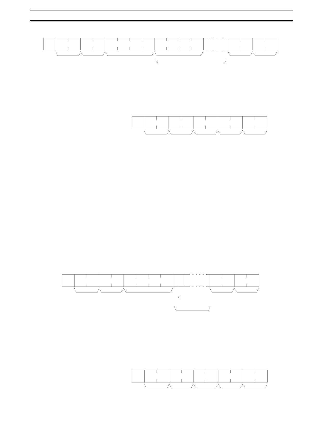
4-5-11 PV WRITE - WC
Writes the PVs (present values) of timers/counters starting from the specified
timer/counter.
282
Host Link Commands
Section
4-5
Command Format
@
x 101 x 100
W
C
x 103 x 102
x 101 x 100
x 103 x 102 x 101 x 100
:
↵
Node no.
Header
Beginning timer/counter* Write data (1 timer/counter)
FCS
Terminator
code
Write data
(for no. of PV to write)
Note
1. Beginning T/C: 0000 to 0255 in CPM2A/CPM2C PCs, 0000 to 0127 in
CPM1/ CPM1A/SRM1(-V2) PCs
2. Divide the command when writing more than 29 words of data.
Response Format
An end code of 00 indicates normal completion.
@
x 10
1 x 100
W
C
x 161 x 160
:
↵
Node no.
Header
End code
FCS
Terminator
code
Parameters
Write Data (Command)
Specify in decimal numbers (BCD) the present values for the number of timers/
counters that are to be written, starting from the beginning timer/counter.
Note
1. When this command is used to write data to the PV area, the Completion
Flags for the timers/counters that are written will be turned OFF.
2. If data is specified for writing which exceeds the allowable range, an error
will be generated and the writing operation will not be executed. If, for exam-
ple, 126 is specified as the beginning word for writing in a CPM1 PC, and
three words of data are specified, then 128 will become the last word for writ-
ing data, and the command will not be executed because TC 128 is beyond
area boundary.
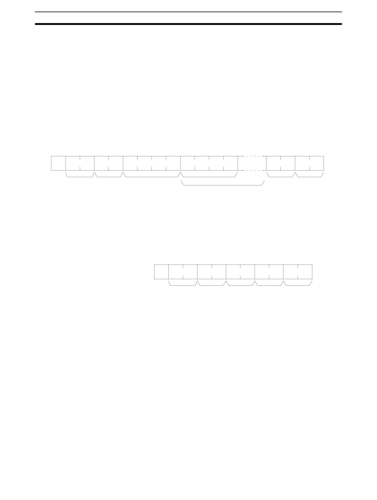
4-5-12 TC STATUS WRITE - WG
Writes the status of the Completion Flags for timers and counters in the TC area,
starting from the specified timer/counter (number). Writing is done number by
number.
Command Format
ON/
@
x 101 x 100
W
G
x 103 x 102
x 101 x 100
:
↵
OFF
Node no.
Header
Beginning timer/counter*
FCS
Terminator
code
Write data
(1 timer/counter)
Write data
(for number of TC to write)
Note
1. Beginning T/C: 0000 to 0255 in CPM2A/CPM2C PCs, 0000 to 0127 in
CPM1/ CPM1A/SRM1(-V2) PCs
2. Divide the command when writing the status of more than 118 timer/count-
ers.
Response Format
An end code of 00 indicates normal completion.
@
x 10
1 x 100
W
G
x 161 x 160
:
↵
Node no.
Header
End code
FCS
Terminator
code
283
Host Link Commands
Section
4-5
Parameters
Write Data (Command)
Specify the status of the Completion Flags, for the number of timers/counters to
be written, in order (from the beginning word) as ON (i.e., “1”) or OFF (i.e., “0”).
When a Completion Flag is ON, it indicates that the time or count is up.
Note If data is specified for writing which exceeds the allowable range, an error will be
generated and the writing operation will not be executed. If, for example, 126 is
specified as the beginning word for writing in a CPM1 PC, and three words of
data are specified, then 128 will become the last word for writing data, and the
command will not be executed because TC 128 is beyond area boundary.
4-5-13 DM AREA WRITE - WD
Writes data to the DM area, starting from the specified word. Writing is done
word by word.
Command Format
@
x 101 x 100
W
D
x 103 x 102
x 101 x 100
x 163 x 162 x 161 x 160
:
↵
Node no.
Header
Beginning word*
Write data (1 word)
FCS
Terminator
code
Write data
(for number of words to write)
Note
1. Beginning word:
DM 0000 to DM 1023 and DM 6144 to DM 6655 in CPM1/CPM1A PCs
DM 0000 to DM 2047 and DM 6144 to DM 6655 in CPM2A/CPM2C/
SRM1(-V2) PCs
2. Divide the command when writing more than 29 words of data.
Response Format
An end code of 00 indicates normal completion.
@
x 10
1 x 100
W
D
x 161 x 160
:
↵
Node no.
Header
End code
FCS
Terminator
code
Note
Words DM 1024 to DM 6143 in CPM1/CPM1A PCs and words DM 2048 to
DM 6143 in CPM2A/CPM2C/SRM1(-V2) PCs cannot be specified. If an attempt
is made to write to any of these words, the writing operation will not be executed
for these words and the command will end normally.
Parameters
Write Data (Command)
Specify in order the contents of the number of words to be written to the DM area
in hexadecimal, starting with the specified beginning word.
Note
1. If data is specified for writing which exceeds the allowable range, an error
will be generated and the writing operation will not be executed. If, for exam-
ple, 1022 is specified as the beginning word for writing in a CPM1 PC, and
three words of data are specified, then 1024 will become the last word for
writing data, and the command will not be executed because DM 1024 is
beyond the writable range.
2. Be careful about the configuration of the DM area, as it varies depending on
the CPU Unit model.
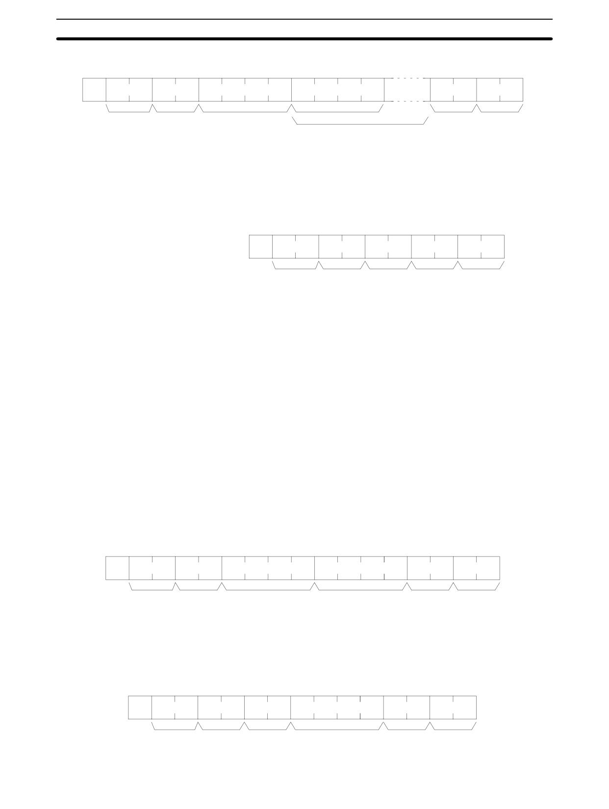
4-5-14 AR AREA WRITE - WJ
Writes data to the AR area, starting from the specified word. Writing is done word
by word.
284
Host Link Commands
Section
4-5
Command Format
@
x 101 x 100
W
J
x 103 x 102
x 101 x 100
x 163 x 162 x 161 x 160
:
↵
Node no.
Header
Beginning word*
Write data (1 word)
FCS
Terminator
code
Write data
(for the number of words to write)
Note
Beginning word: 0000 to 0023 in CPM2A/CPM2C PCs, 0000 to 0015 in
CPM1/CPM1A and SRM1(-V2) PCs
Response Format
An end code of 00 indicates normal completion.
@
x 10
1 x 100
W
J
x 161 x 160
::
↵
Node no.
Header
End code
FCS
Terminator
code
Parameters
Write Data (Command)
Specify in order the contents of the number of words to be written to the AR area
in hexadecimal, starting with the specified beginning word.
Note
If data is specified for writing which exceeds the allowable range, an error will be
generated and the writing operation will not be executed. If, for example, 12 is
specified as the beginning word for writing in a CPM1 PC, and five words of data
are specified, then 16 will become the last word for writing data, and the com-
mand will not be executed because AR 16 is beyond the writable range.
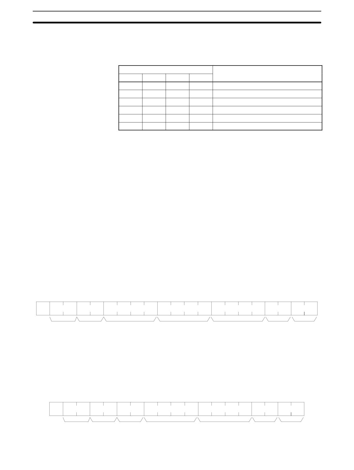
4-5-15 SV READ 1 - R#
Searches for the first instance of a timer or counter instruction (TIM, TIMH(15),
TIML(--), TMHH(--), CNT, or CNTR(12)) with the specified TC number in the
user’s program and reads the PV, which is assumed to be set as a constant. The
SV that is read is a 4-digit decimal number (BCD). The program is searched from
the beginning, which may take as much as 10 seconds to produce a response.
Command Format
@
x 101 x 100
R
#
OP1 OP2
OP3 OP4
x 103 x 102 x 101 x 100
:
↵
Node no.
Header
Name
TC number*
FCS
Terminator
code
Note TC number: 0000 to 0255 in CPM2A/CPM2C PCs and 0000 to 0127 in
CPM1/CPM1A/SRM1(-V2) PCs
Response Format
@
x 10
1 x 100
R
#
x 161 x 160
x 103 x 102 x 101 x 100
:
↵
Node no.
Header
End code
SV
FCS
Terminator
code
285
Host Link Commands
Section
4-5
Parameters
Name, TC Number (Command)
Specify the instruction for reading the SV in “Name.” Make this setting in 4 char-
acters. In “TC number,” specify the timer/counter number used for the instruc-
tion.
Name
Instruction name
OP1
OP2
OP3
OP4
T
I
M
(Space)
TIMER
T
I
M
H
HIGH-SPEED TIMER
T
I
M
L
LONG TIMER
T
M
H
H
VERY HIGH-SPEED TIMER
C
N
T
(Space)
COUNTER
C
N
T
R
REVERSIBLE COUNTER
SV (Response)
The constant SV is returned.
Note
1. The instruction specified under “Name” must be in four characters.
2. If the same instruction is used more than once in a program, only the first one
will be read.
3. Use this command only when it is definite that a constant SV has been set.
4. The response end code will indicate an error (16) if the SV wasn’t entered as
a constant.
4-5-16 SV READ 2 - R$
Reads the constant SV or the word address where the SV is stored. The SV that
is read is a 4-digit decimal number (BCD) written as the second operand for the
TIM, TIMH(15), TIML(--), TMHH(--), CNT, or CNTR(12) instruction at the spe-
cified program address in the user’s program. This can only be done with a pro-
gram of less than 10K.
Command Format
@
x 101
x 10
0
R
$
x 103 x 102 x 101
x 100
OP1 OP2
OP3
OP4
x 103 x 102 x 101
x 100
:
↵
Node no.
Header
Program
Name
TC number*
FCS
Terminator
code
address
Note TC number: 0000 to 0255 in CPM2A/CPM2C PCs and 0000 to 0127 in
CPM1/CPM1A/SRM1(-V2) PCs
Response Format
An end code of 00 indicates normal completion.
@
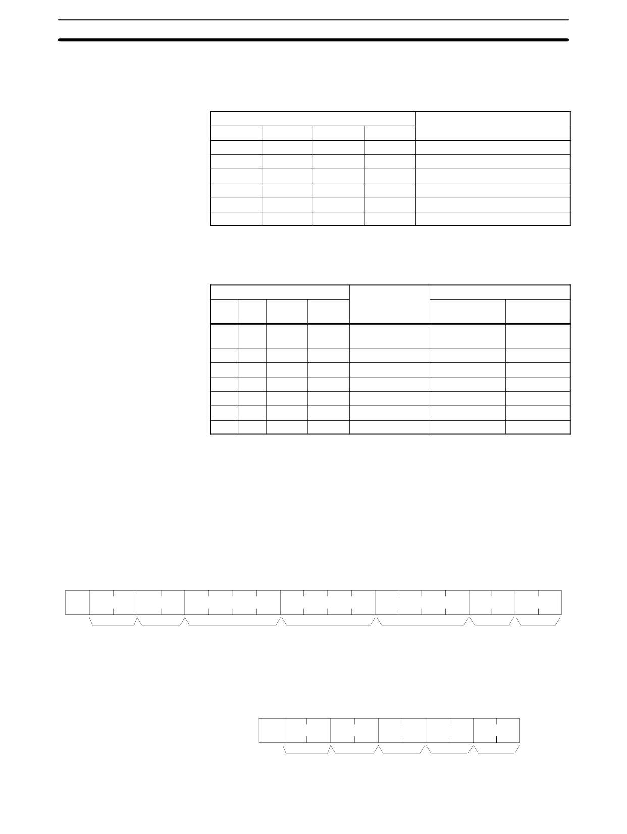
x 101
x 100
R
$
x 161
x 160
OP1 OP2
OP3
OP4
x 103 x 102 x 101
x 100
:
↵
Node no.
Header
End code
Operand
SV
FCS
Terminator
code
286
Host Link Commands
Section
4-5
Parameters
Name, TC Number (Command)
Specify the name of the instruction for reading the SV in “Name.” Make this set-
ting in 4 characters. In “TC number,” specify the timer/counter number used by
the instruction.
Name
Instruction name
OP1
OP2
OP3
OP4
T
I
M
(Space)
TIMER
T
I
M
H
HIGH-SPEED TIMER
T
I
M
L
LONG TIMER
T
M
H
H
VERY HIGH-SPEED TIMER
C
N
T
(Space)
COUNTER
C
N
T
R
REVERSIBLE COUNTER
Operand, SV (Response)
The name that indicates the SV classification is returned to “Operand,” and ei-
ther the word address where the SV is stored or the constant SV is returned to
“SV.”
Operand
Classification
Constant or word address
OP1
OP2
OP3
OP4
CPM2A/
CPM1 PCs
CPM2C PCs
C
I
O
(Space)
IR or SR
0000 to 0049
0000 to 0019
0200 to 0255
0200 to 0255
L
R
(Space)
(Space)
LR
0000 to 0015
0000 to 0015
H
R
(Space)
(Space)
HR
0000 to 0019
0000 to 0019
A
R
(Space)
(Space)
AR
0000 to 0023
0000 to 0015
D
M
(Space)
(Space)
DM
0000 to 6655
0000 to 6655
D
M
:
(Space)
DM (indirect)
0000 to 6655
0000 to 6655
C
O
N
(Space)
Constant
0000 to 9999
0000 to 9999
Note The instruction name specified under “Name” must be in four characters. Fill any
gaps with spaces to make a total of four characters.
4-5-17 SV CHANGE 1 - W#
Searches for the first instance of the specified TIM, TIMH(15), TIML(--),
TMHH(--), CNT, or CNTR(12) instruction in the user’s program and changes
the SV to new constant SV specified in the second word of the instruction. The
program is searched from the beginning, and it may therefore take approximate-
ly 10 seconds to produce a response.
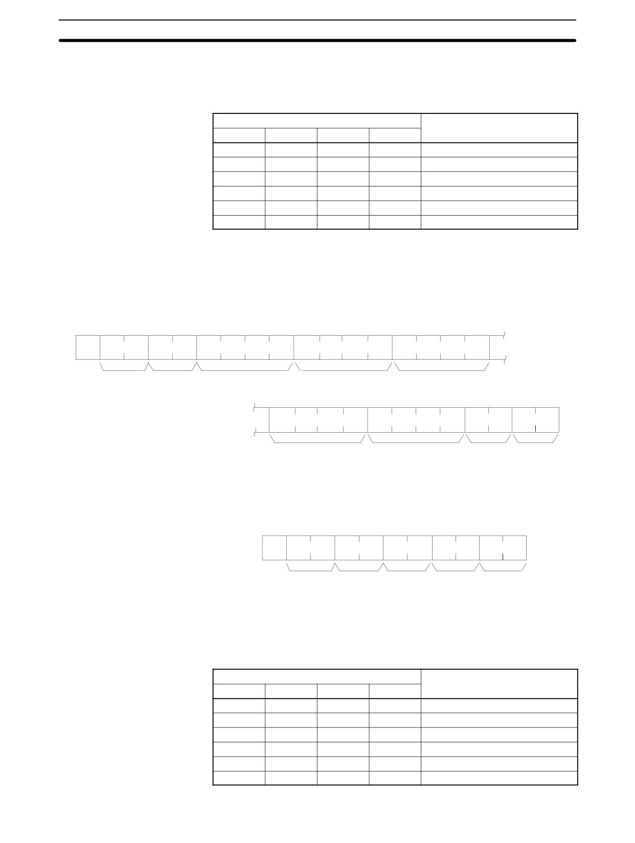
Command Format
0
@
x 101
x 10
W
#
OP1 OP2
OP3
OP4
x 103 x 102
x 101
x 100
x 103 x 102
x 101
x 100
:
↵
Node no.
Header
Name
TC number*
SV (0000 to 9999)
FCS
Terminator
code
Note TC number: 0000 to 0255 in CPM2A/CPM2C PCs and 0000 to 0127 in
CPM1/CPM1A/SRM1(-V2) PCs
Response Format
An end code of 00 indicates normal completion.
@
x 101
x 100
W
#
x 161
x 160
:
↵
Node no.
Header
End code
FCS
Terminator
code
287
Host Link Commands
Section
4-5
Parameters
Name, TC Number (Command)
In “Name,” specify the name of the instruction, in four characters, for changing
the SV. In “TC number,” specify the timer/counter number used for the instruc-
tion.
Instruction name
Classification
OP1
OP2
OP3
OP4
T
I
M
(Space)
TIMER
T
I
M
H
HIGH-SPEED TIMER
T
I
M
L
LONG TIMER
T
M
H
H
VERY HIGH-SPEED TIMER
C
N
T
(Space)
COUNTER
C
N
T
R
REVERSIBLE COUNTER
4-5-18 SV CHANGE 2 - W$
Changes the contents of the second word of the TIM, TIMH(15), TIML(--),
TMHH(--), CNT, or CNTR(12) at the specified program address in the user’s
program. This can only be done with a program of less than 10K.
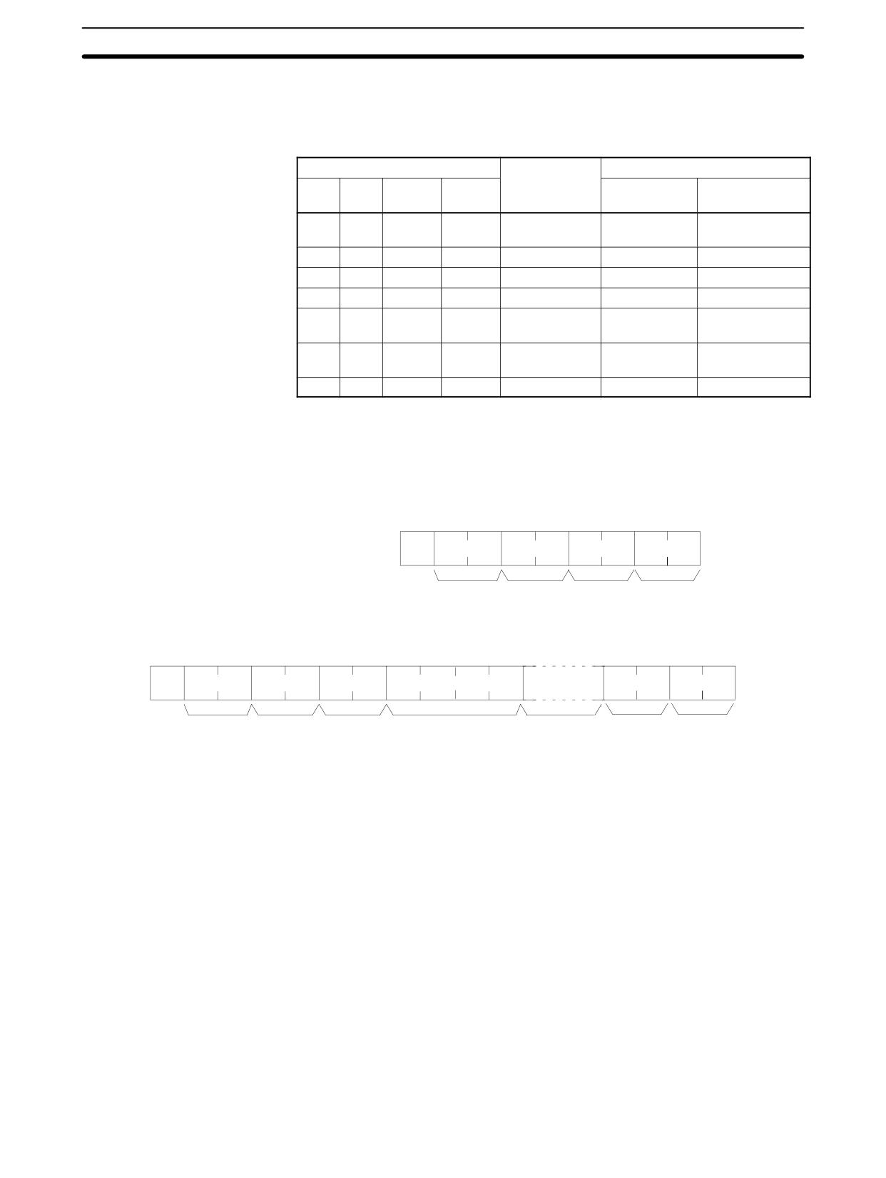
Command Format
@
x 101
x 100
W
$
x 103 x 102 x 101
x 10
0
OP1 OP2
OP3
OP4
x 103 x 102 x 101
x 100
Node no.
Header
Program
Name
TC number
code
address
OP1 OP2
OP3
OP4
x 103 x 102 x 101
x 100
:
↵
Operand
SV
FCS
Terminator
Note TC number: 0000 to 0255 in CPM2A/CPM2C PCs and 0000 to 0127 in
CPM1/CPM1A/SRM1(-V2) PCs
Response Format
An end code of 00 indicates normal completion.
@
x 101
x 100
W
$
x 161
x 160
:
↵
Node no.
Header
End code
FCS
Terminator
code
Parameters
Name, TC Number (Command)
In “Name,” specify the name of the instruction, in four characters, for changing
the SV. In “TC number,” specify the timer/counter number used for the instruc-
tion.
Instruction name
Classification
OP1
OP2
OP3
OP4
T
I
M
(Space)
TIMER
T
I
M
H
HIGH-SPEED TIMER
T
I
M
L
LONG TIMER
T
M
H
H
VERY HIGH-SPEED TIMER
C
N
T
(Space)
COUNTER
C
N
T
R
REVERSIBLE COUNTER
288
Host Link Commands
Section
4-5
Operand, SV (Response)
In “Operand,” specify the name that indicates the SV classification. Specify the
name in four characters. In “SV,” specify either the word address where the SV is
stored or the constant SV.
Operand
Classification
Constant or word address
OP1
OP2
OP3
OP4
CPM2A/
CPM1/CPM1A/
CPM2C PCs
SRM1(-V2) PCs
C
I
O
(Space)
IR or SR
0000 to 0049
0000 to 0019
0200 to 0252
0200 to 0252
L
R
(Space)
(Space)
LR
0000 to 0015
0000 to 0015
H
R
(Space)
(Space)
HR
0000 to 0019
0000 to 0019
A
R
(Space)
(Space)
AR
0000 to 0023
0000 to 0015
D
M
(Space)
(Space)
DM
0000 to 2047
0000 to 1023*
6144 to 6655
6144 to 6655
D
M
:
(Space)
DM (indirect)
0000 to 2047
0000 to 1023*
6144 to 6655
6144 to 6655
C
O
N
(Space)
Constant
0000 to 9999
0000 to 9999
Note *For SRM1(-V2) PCs, the DM range is from 0000 to 2047.
4-5-19 STATUS READ - MS
Reads the PC operating conditions.
Command Format
0
@
x 101
x 10
M
S
:
↵
Node no.
Header
FCS
Terminator
code
Response Format
An end code of 00 indicates normal completion.
@
x 101
x 100
M
S
x 161 x 160
x 163
x 162
x 161
x 160
16 characters
:
↵
Node no.
Header
End code
Status data
Message
FCS
Terminator
code
289
Host Link Commands
Section
4-5
Parameters
Status Data, Message (Response)
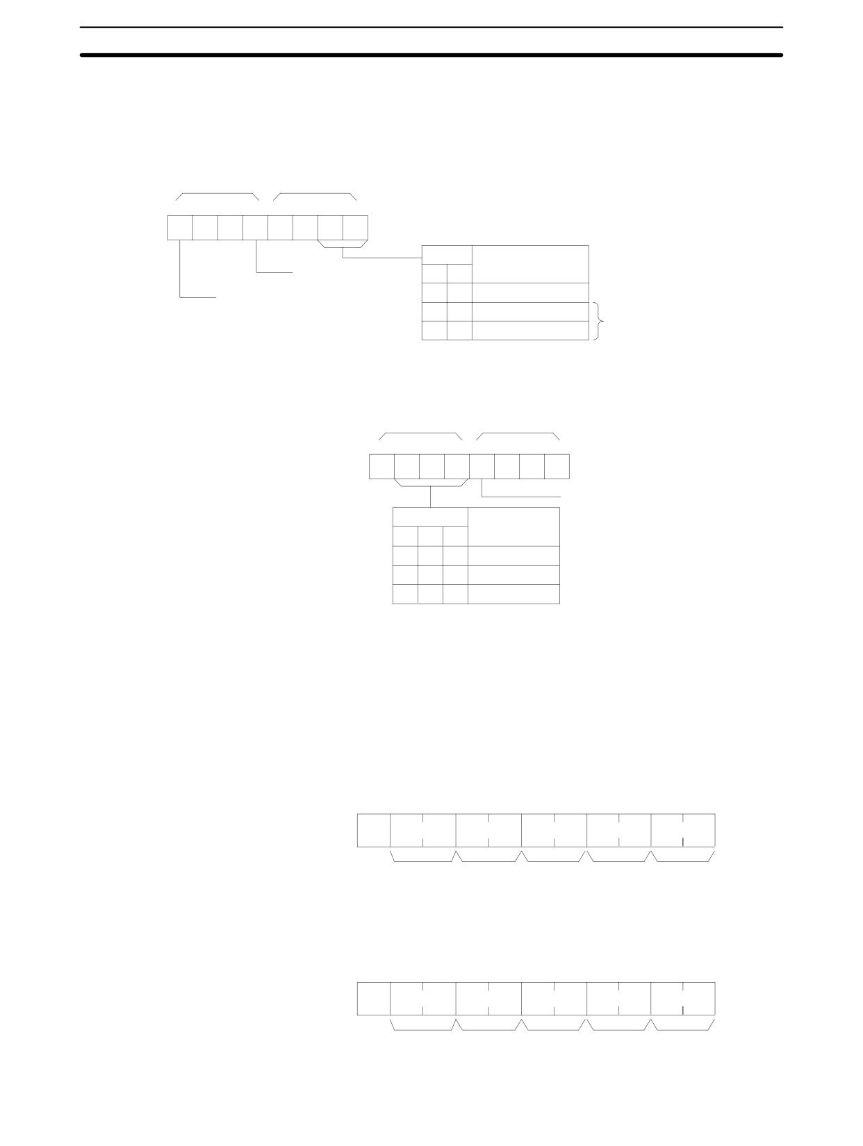
“Status data” consists of four digits (two bytes) hexadecimal. The leftmost byte
indicates CPU Unit operation mode, and the rightmost byte indicates the size of
the program area.
x 163
x 162
Bit
15
14
13
12
11
10
9
8
0
0
0
0
Bit
Operation mode
1: Fatal error generated
9
8
0
0
PROGRAM mode
1: FALS generated
1
0
RUN mode
This area is different
1
1
MONITOR mode
from that of STATUS
WRITE.
x 161
x 160
Bit
7
6
5
4
3
2
1
0
1
0
0
0
Program area write-protection
0: Write-protected
Bit
Program area
1: Not write-protected
6
5
4
0
0
0
None
0
0
1
4 Kbytes
0
1
0
8 Kbytes
The “Message” parameter is a 16-character message that exists when MSG(47)
has been executed. When there is no message, this parameter is omitted.
4-5-20 STATUS WRITE - SC
Changes the PC operating mode.
Command Format
@
x 101
x 10
0
S
C
x 161 x 160
:
↵
Node no.
Header
Mode data
FCS
Terminator
code
Response Format
An end code of 00 indicates normal completion.
@
x 101
x 10
0
S
C
x 161 x 160
:
↵
Node no.
Header
End code
FCS
Terminator
code
290
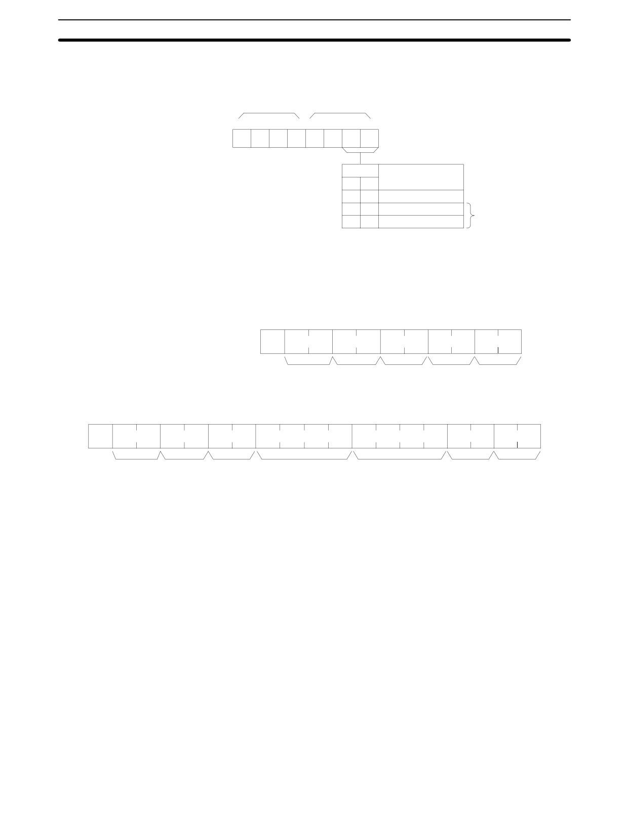
Host Link Commands
Section
4-5
Parameters
Mode Data (Command)
“Mode data” consists of two digits (one byte) hexadecimal. With the leftmost two
bits, specify the PC operating mode. Set all of the remaining bits to “0.”
x 161
x 160
Bit
7
6
5
4
3
2
1
0
0
0
0
0
0
0
Bit
Operation mode
1
0
0
0
PROGRAM mode
1
0
MONITOR mode
This area is different
1
1
RUN mode
from that of STATUS
READ.
4-5-21 ERROR READ - MF
Reads and clears errors in the PC. Also checks whether previous errors have
been cleared.
Command Format
@
x 101
x 10
0
M
F
x 101 x 100
:
↵
Node no.
Header
Error clear
FCS
Terminator
code
Response Format
An end code of 00 indicates normal completion.
@
x 101
x 10
0
M
F
x 161 x 160
x 163 x 162 x 161 x 160
x 163 x 162 x 161 x 160
:
↵
Node no.
Header
End code
Error information
Error information
FCS
Terminator
code
(1st word)
(2nd word)
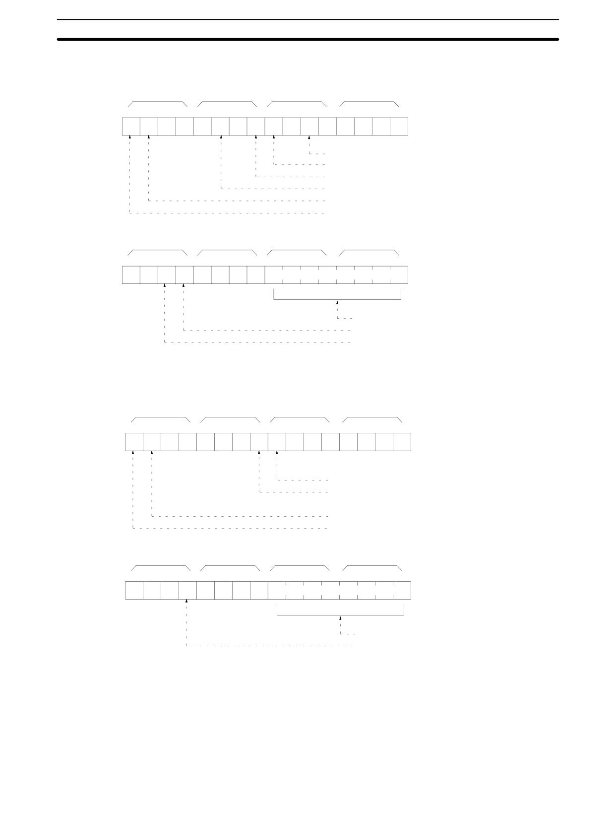
Parameters
Error Clear (Command)
Specify 01 to clear errors and 00 to not clear errors (BCD). Fatal errors can be
cleared only when the PC is in PROGRAM mode.
Error Information (Response)
The error information comes in two words.
291
Host Link Commands
Section
4-5
CPM1/CPM1A/CPM2A/CPM2C PCs
1st word
x 163
x 162
x 161
x 160
Bit
15
14
13
12
11
10
9
8
7
6
5
4
3
2
1
0
0
0
0
0
0
0
0
0
0
0
ON: Battery alarm (F7)
ON: System error (FAL)
ON: Memory error (Error code F1)
ON: I/O bus error (Error code C0)
ON: No end instruction error (FALS)
ON: System error (FAL)
2nd word
x 163
x 162
x 161
x 160
Bit
15
14
13
12
11
10
9
8
7
6
5
4
3
2
1
0
0
0
0
0
0
0
FAL, FALS No. (00 to FF)
ON: Cycle time overrun (Error code F8)
ON: I/O Unit overflow (Error code E1)
SRM1(-V2) PCs
1st word
x 163
x 162
x 161
x 160
Bit
15
14
13
12
11
10
9
8
7
6
5
4
3
2
1
0
0
0
0
0
0
0
0
0
0
0
0
0
ON: System error (FAL)
ON: Memory error (Error code F1)
ON: No end instruction error (FALS)
ON: System error (FAL)
2nd word
x 163
x 162
x 161
x 160
Bit
15
14
13
12
11
10
9
8
7
6
5
4
3
2
1
0
0
0
0
0
0
0
0
FAL, FALS No. (00 to 99)
ON: Cycle time overrun (Error code F8)
4-5-22 FORCED SET - KS
Force sets a bit in the IR, SR, LR, HR, AR, or TC area. Just one bit can be force
set at a time.
Once a bit has been forced set or reset, that status will be retained until a
FORCED SET/RESET CANCEL (KC) command or the next FORCED SET/RE-
SET command is transmitted.
292
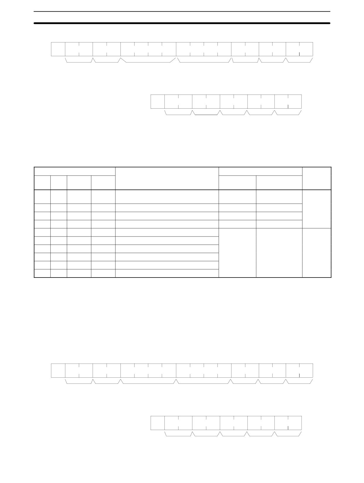
Host Link Commands
Section
4-5
Command Format
@
x 101
x 10
0
K
S
OP1 OP2 OP3 OP4
x 103 x 102 x 101 x 100
x 101 x 100
:
↵
Node no.
Header
Name
Word
Bit
FCS
Terminator
code
address
Response Format
An end code of 00 indicates normal completion.
@
x 101
x 10
0
K
S
x 161 x 160
:
↵
Node no.
Header
End code
FCS
Terminator
code
Parameters
Name, Word address, Bit (Command)
In “Name,” specify the area (i.e., IR, SR, LR, HR, AR, or TC) that is to be forced
set. Specify the name in four characters. In “Word address,” specify the address
of the word, and in “Bit” the number of the bit that is to be forced set.
Name
Classification
Word address setting range
Bit
OP1
OP2
OP3
OP4
CPM2A/
CPM1/ CPM1A/
CPM2C PCs
SRM1(-V2) PCs
C
I
O
(Space)
IR or SR
0000 to 0049
0000 to 0019
00 to 15
0200 to 0252
0200 to 0252
(decimal)
L
R
(Space)
(Space)
LR
0000 to 0015
0000 to 0015
H
R
(Space)
(Space)
HR
0000 to 0019
0000 to 0019
A
R
(Space)
(Space)
AR
0000 to 0023
0000 to 0015
T
I
M
(Space)
Completion Flag (timer)
0000 to 0255
0000 to 0127
Always
00
T
I
M
H
Completion Flag (high-speed timer)
T
I
M
L
Completion Flag (long timer)
T
M
H
H
Completion Flag (very high-speed timer)
C
N
T
(Space)
Completion Flag (counter)
C
N
T
R
Completion Flag (reversible counter)
Note The area specified under “Name” must be in four characters. Add spaces after
the data area name if it is shorter than four characters.
4-5-23 FORCED RESET - KR
Force resets a bit in the IR, SR, LR, HR, AR, or TC area. Just one bit can be force
reset at a time.
Once a bit has been forced set or reset, that status will be retained until a
FORCED SET/RESET CANCEL (KC) command or the next FORCED SET/RE-
SET command is transmitted.
Command Format
@
x 101
x 10
0
K
R
OP1 OP2 OP3 OP4
x 103 x 102 x 101 x 100
x 101 x 100
:
↵
Node no.
Header
Name
Word
Bit
FCS
Terminator
code
address
Response Format
An end code of 00 indicates normal completion.
@
x 101
x 10
0
K
R
x 161 x 160
:
↵
Node no.
Header
End code
FCS
Terminator
code
293
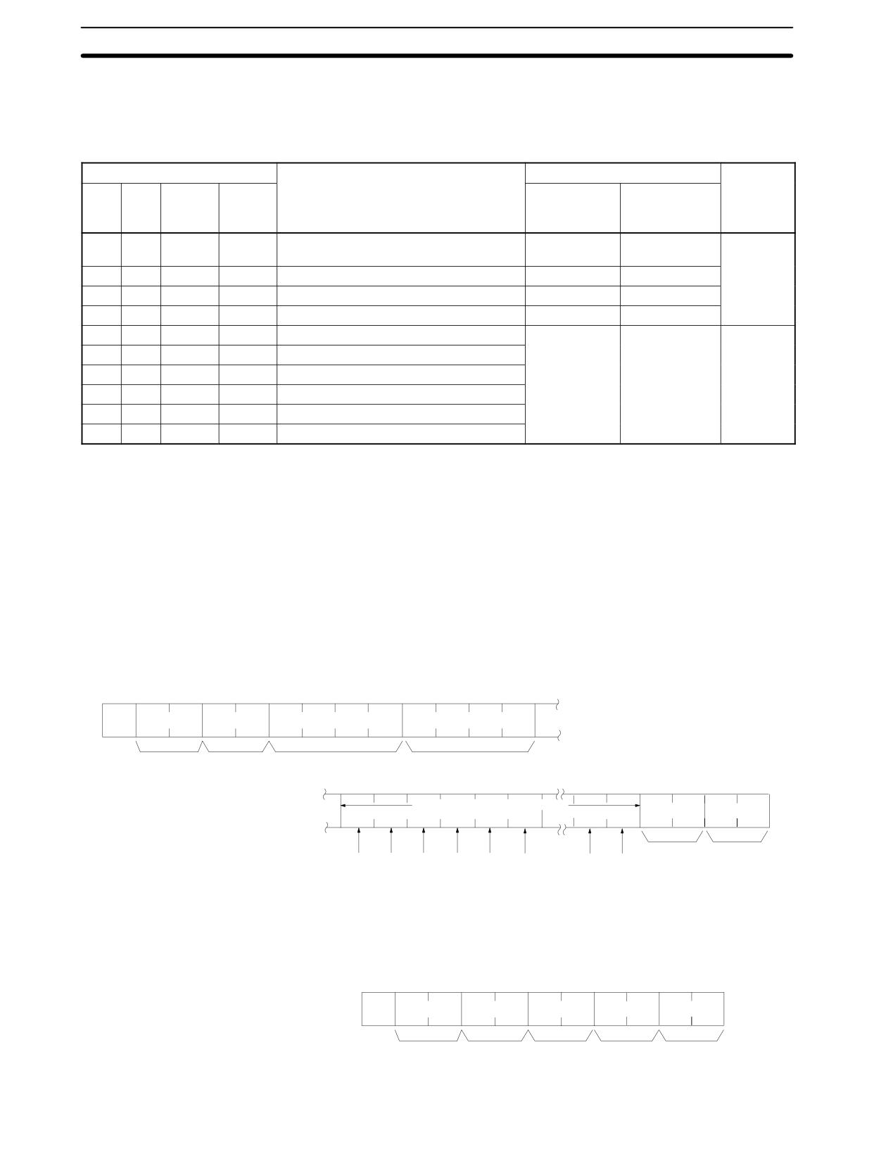
Host Link Commands
Section
4-5
Parameters
Name, Word address, Bit (Command)
In “Name,” specify the area (i.e., IR, SR, LR, HR, AR, or TC) that is to be forced
reset. Specify the name in four characters. In “Word address,” specify the ad-
dress of the word, and in “Bit” the number of the bit that is to be forced reset.
Name
Classification
Word address setting range
Bit
OP1
OP2
OP3
OP4
CPM2A/
CPM1/CPM1A
CPM2C PCs
/SRM1(-V2)
PCs
C
I
O
(Space)
IR or SR
0000 to 0049
0000 to 0019
00 to 15
0200 to 0252
0200 to 0252
(decimal)
L
R
(Space)
(Space)
LR
0000 to 0015
0000 to 0015
H
R
(Space)
(Space)
HR
0000 to 0019
0000 to 0019
A
R
(Space)
(Space)
AR
0000 to 0023
0000 to 0015
T
I
M
(Space)
Completion Flag (timer)
0000 to 0255
0000 to 0127
Always 00
T
I
M
H
Completion Flag (high-speed timer)
T
I
M
L
Completion Flag (long timer)
T
M
H
H
Completion Flag (very high-speed timer)
C
N
T
(Space)
Completion Flag (counter)
C
N
T
R
Completion Flag (reversible counter)
Note The area specified under “Name” must be in four characters. Add spaces after
the data area name if it is shorter than four characters.
4-5-24 MULTIPLE FORCED SET/RESET - FK
Force sets, force resets, or cancels the status of the bits in one word in the IR,
SR, LR, HR, AR, or TC area.
Command Format
@
x 101
x 10
0
F
K
OP1 OP2 OP3 OP4
x 103 x 102 x 101 x 100
Node no.
Header
Name
Word
code
address
Forced set/reset/cancel data
:
↵
x 160 x 160
x 160 x 160 x 160
x 160
x 160
x 160
FCS
Terminator
Bit
15
14
13
12
11
10
1
0
Response Format
An end code of 00 indicates normal completion.
@
x 101
x 10
0
F
K
x 161 x 160
:
↵
Node no.
Header
End code
FCS
Terminator
code
294