SYSMAC CPM1/CPM1A/CPM2A/CPM2C/SRM1(–V2). Programmable Controllers (2001) - page 3
Analog I/O Units
Section
3-1
For analog outputs it is possible to use both voltage outputs and current outputs
at the same time, but the total current output must not exceed 21 mA.
Note
1. Use 2-core shielded twisted-pair cables.
2. Wire away from power lines (AC power supply wires, power lines, etc.)
3. When an input is not being used, short V IN and I IN to the COM terminal.
4. Use crimp terminals. (Tighten terminals to a torque of 0.5 N⋅m.)
5. When using current inputs, short V IN to I IN.
6. When there is noise in the power supply line, install a noise filter on the input
section and the Power Supply Unit.
Ladder Program
Specifying the Range Code
Specify the I/O signal range by writing the range code to the Analog I/O Unit’s
output word from the ladder program in the first cycle of program execution. The
Analog I/O Unit will start to convert analog I/O values once the range code has
been specified. (Refer to page 166.)
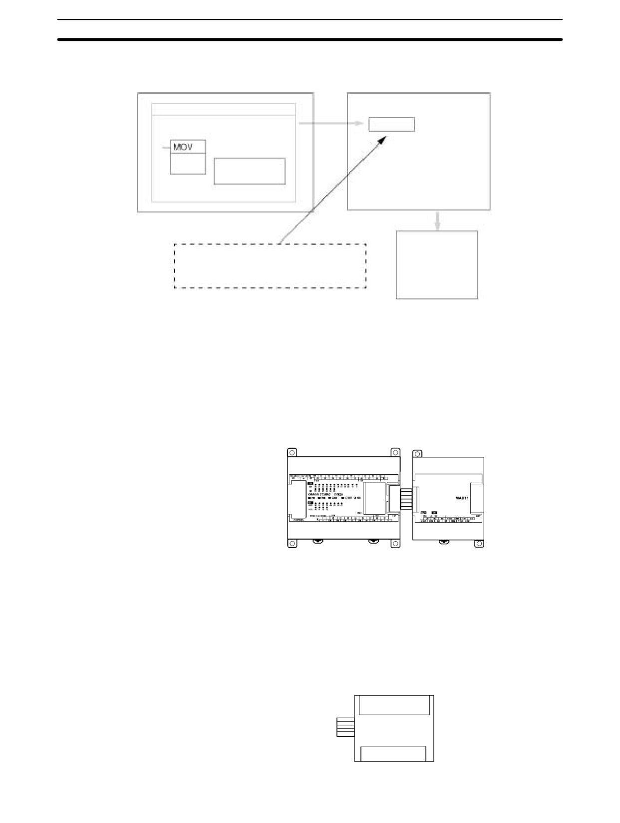
Write the range code to the Analog I/O Unit’s output word in the first cycle of op-
eration; the Analog I/O Unit’s output word is “n+1” when “n” is the last word allo-
cated to the CPU Unit, or previous Expansion Unit or Expansion I/O Unit in the
configuration.
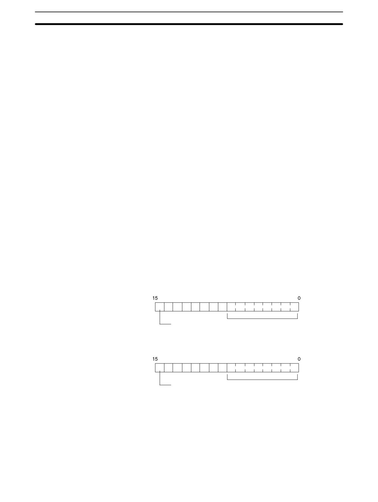
Reading Converted Analog Input Values
A ladder program can be used to read the memory area where the converted
values are stored. Values are output to the next two words (m + 1, m + 2) follow-
ing the last input word (m) allocated to the CPU Unit, or previous Expansion Unit
or Expansion I/O Unit.
(m + 1)
0
0
0
0
0
0
0
Analog input 1
Analog input 1 conversion value (Hex: 00 to FF)
Open-circuit
Detection Flag
0: Normal
1: Open-circuit
(m + 2)
0
0
0
0
0
0
0
Analog input 2
Analog input 2 conversion value (Hex: 00 to FF)
Open-circuit
Detection Flag
0: Normal
1: Open-circuit
Note The Open-circuit Detection Flag is turned ON when the input signal range is set
to 1 to 5 V or 4 to 20 mA and the input signal falls below 1 V or 4 mA. (Open cir-
cuits are not detected when the input signal range is set to 0 to 10 V.)
169
Analog I/O Units
Section
3-1
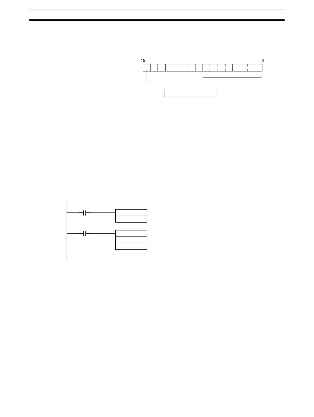
Writing Analog Output Set Values
A ladder program can be used to write data to the output word where the set val-
ue is stored. The output word will be “n+1” when “n” is the last output word allo-
cated to the CPU Unit, or previous Expansion Unit or Expansion I/O Unit.
(n + 1)
0
0
0
0
0
0
0
Sign bit
(Used when the output sig-
Set value (Hex: 00 to FF)
nal range is -10 to 10 V.)
1, 2, 3...
1. The set value range is 0000 to 00FF when the output signal range is 0 to
10 V/4 to 20 mA.
2. The set value range is divided into two parts: 80FF to 8000 (-10 to 0 V) and
0000 to 00FF (0 to 10 V) when the output signal range is -10 to 10 V.
Startup Operation
After power is turned ON, it will require two cycle times plus approx. 100 ms be-
fore the first data is converted. The following instructions can be placed at the
beginning of the program to delay reading converted data from analog inputs
until conversion is actually possible.
Note Analog input data will be 0000 until initial processing has been completed. Ana-
log output data will be 0 V or 0 mA until the range code has been written. After the
range code has been written, the analog output data will be 0 V or 4 mA if the
range is 0 to 10 V, -10 to 10 V, or 4 to 20 mA.
SR 25315
(Always ON Flag)
TIM 000
TIM 000 will start as soon as power turns ON.
#0003
After 0.2 to 0.3 s (200 to 300 ms), the Comple-
T005
tion Flag for TIM 000 will turn ON, and the con-
verted data from analog input will be read from
MOV (21)
IR 001 and stored in DM 0000.
001
DM0000
Handling Unit Errors
If an error occurs in an Analog I/O Unit, the Error Flags in AR 0200 to AR 0204 will
be turned ON. The addresses of the Error Flags are in the order that the Expan-
sion Units and Expansion I/O Units are connected in the PC, with AR 0200 used
for the Expansion Unit or Expansion I/O Unit closest to the CPU Unit. Use these
flags in the program when it is necessary to detect errors.
When an error occurs in the Analog I/O Unit, analog input data will be 0000 and
0 V or 4 mA will be output as the analog output.
170
Analog I/O Units
Section
3-1
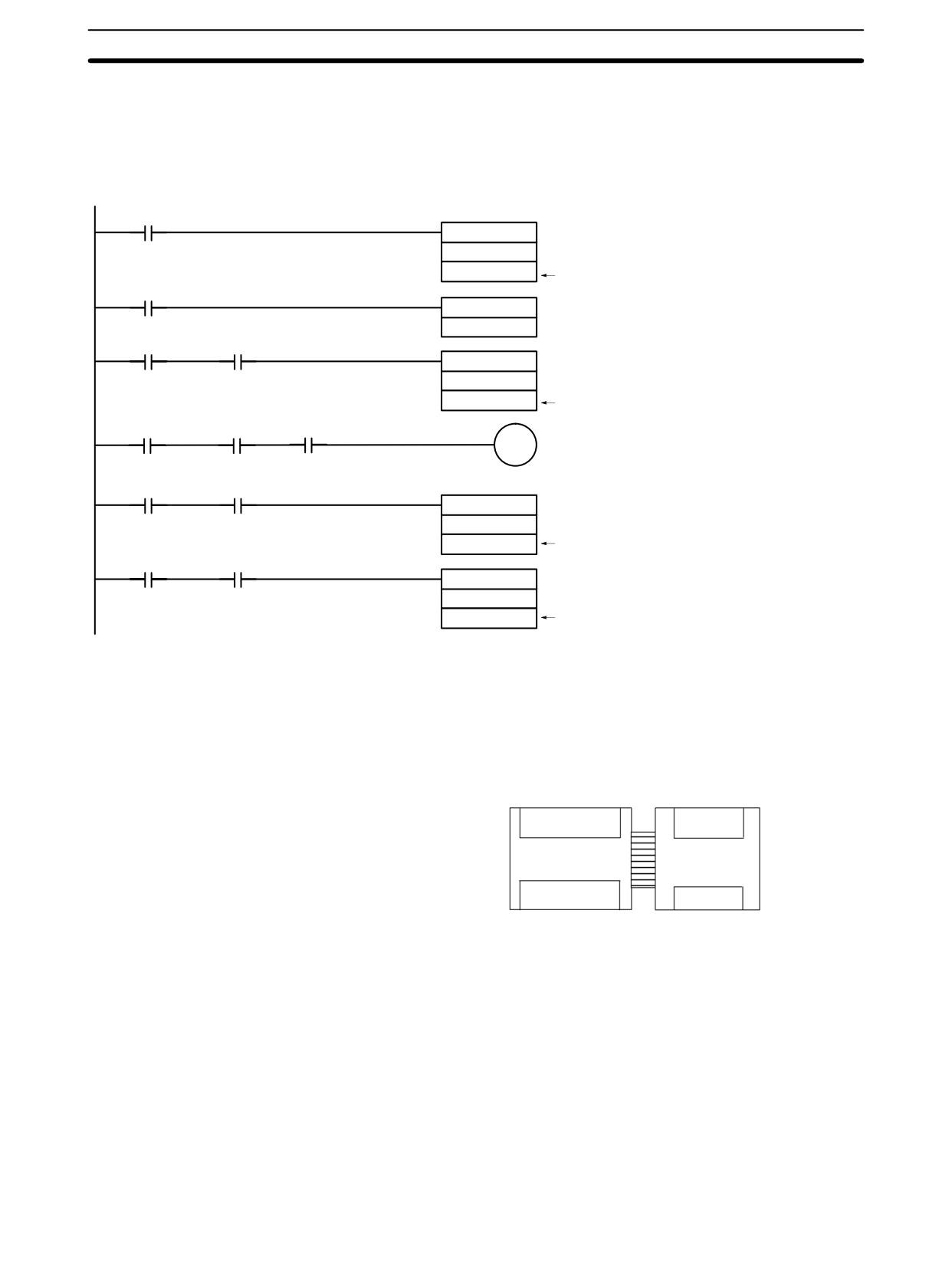
Programming Example
This programming example uses these ranges:
Analog input 0: 0 to 10 V
Analog input 1: 1 to 5 V or 4 to 20 mA
Analog output:
0 to 10 V or 4 to 20 mA
25135
(First Cycle ON Flag)
MOV (21)
#FF04
011
25313
Writes the range code (FF04) to the Unit.
(Always ON Flag)
TIM 000
#0003
Execution
TIM000
condition
MOV (21)
001
DM0000
Reads analog input 0’s converted value.
Execution
TIM000
condition
00215
01000
Open-circuit alarm
Execution
TIM000
condition
MOV (21)
002
DM0001
Reads analog input 1’s converted value.
Execution
TIM000
condition
MOV (21)
DM0010
011
The content of DM 0010 is written to the output
word as the analog output set value.
Example
Analog Input Program Example
Analog I/O Unit Connection
In this example, an Analog I/O Unit is connected to a CPU Unit with 30 I/O points.
I/O words are allocated to the Analog I/O Unit beginning with the next word ad-
dress following the last words allocated to the CPU Unit.
IR 000
IR 002
Input words
IR 001
IR 003
CPU Unit with
Analog I/O
30 I/O points
Unit
IR 010
Output words
IR 012
IR 011
171
Analog I/O Units
Section
3-1
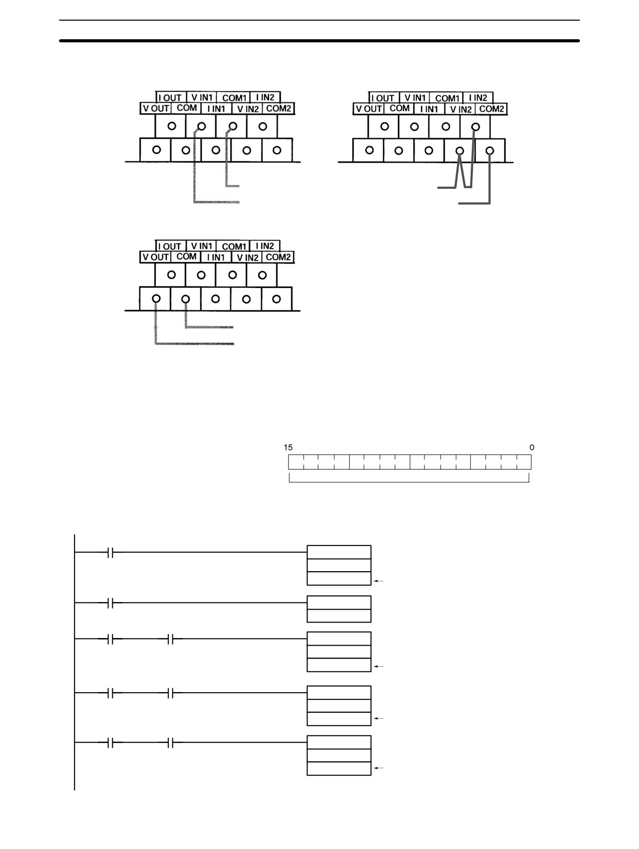
Analog I/O Wiring
Using analog input 1 as a voltage input
Using analog input 2 as a current input
Common (-)
Current input 2 (+)
Voltage input 1 (+)
Common (-)
Using analog output as a voltage output
Common (-)
Voltage output (+)
Analog I/O Settings
Input 1 signal range:
0 to 10 V
Input 2 signal range:
4 to 20 mA
Output signal range:
0 to 10 V
Range Code Setting:
FF04
IR 012
Range code: FF04
Program
25135
(First Cycle ON Flag)
MOV (21)
#FF04
012
25313
Writes the range code (FF04) to the Unit.
(Always ON Flag)
TIM 000
#0003
Execution
TIM000
condition
MOV (21)
002
DM0000
Reads analog input 1’s converted value.
Execution
TIM000
condition
MOV (21)
003
DM0001
Reads analog input 2’s converted value.
Execution
TIM000
condition
MOV (21)
DM0010
012
The content of DM0010 is written to the output
word as the analog output set value.
172
Analog I/O Units
Section
3-1
3-1-2
CPM1A-MAD11 and CPM2C-MAD11 Analog I/O Units
The following information applies to both the CPM1A-MAD11 and CPM2C-
MAD11 Analog I/O Units unless otherwise specified.
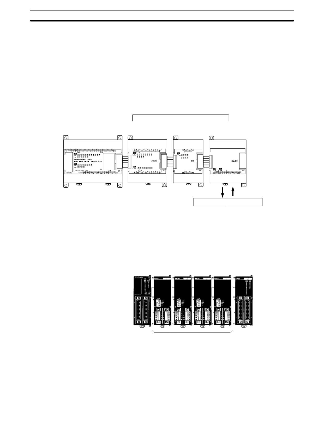
A maximum of 3 Expansion Units or Expansion I/O Units, including up to 3
CPM1A-MAD11 Analog I/O Units, can be connected to a CPM2A or CPM1A.
One Analog I/O Unit allows 2 analog inputs and 1 analog output. With the maxi-
mum of 3 Analog I/O Units connected, 6 analog inputs and 3 analog outputs are
possible.
Possible to connect to a maximum of
3 Units including Expansion I/O Units
CPM1A/CPM2A
CPM1A-20EDR1
CPM1A-8ED
CPM1A-MAD11
CPU Unit
Expansion I/O Unit
Expansion I/O Unit
Analog I/O Unit
1 analog output
2 analog inputs
A maximum of 5 Expansion Units or Expansion I/O Units, including up to 4
CPM2C-MAD11 Analog I/O Units, can be connected to a CPM2C (A maximum
of 3 Units can be connected to the CPM2C-S). One Analog I/O Unit allows 2 ana-
log inputs and 1 analog output. With the maximum of 4 Analog I/O Units con-
nected, 8 analog inputs and 4 analog outputs are possible.
CPM2C
CPU Unit
CPM2C-MAD11 Analog I/O Units
Expansion I/O Unit
Two analog inputs and one
analog output for each Unit
• The analog input range can be set to 0 to 5 VDC, 1 to 5 VDC, 0 to 10 VDC, -10
to 10 VDC, 0 to 20 mA, or 4 to 20 mA. The inputs have a resolution of 1/6000.
• An open-circuit detection function can be used with the 1 to 5 VDC and 4 to
20 mA settings.
• The analog output range can be set to 1 to 5 VDC, 0 to 10 VDC, -10 to 10 VDC,
0 to 20 mA, or 4 to 20 mA. The outputs have a resolution of 1/6000.
173
Analog I/O Units
Section
3-1
Item
Voltage I/O
Current I/O
Analog
Number of inputs
2 inputs (2 words allocated)
Input
Input signal range
0 to 5 VDC, 1 to 5 VDC,
0 to 20 mA or 4 to 20 mA
Section
0 to 10 VDC, or -10 to 10 VDC
Max. rated input
±15 V
±30 mA
External input impedance
1 MΩ min.
250 Ω
Resolution
1/6000 (full scale)
Overall accuracy
25°C
0.3% full scale
0.4% full scale
0 to 55°C
0.6% full scale
0.8% full scale
A/D conversion data
16-bit binary (4-digit hexadecimal)
Full scale for -10 to 10 V: F448 to 0BB8 Hex
Full scale for other ranges: 0000 to 1770 Hex
Averaging function
Supported (Settable for individual inputs via DIP switch)
Open-circuit detection function
Supported
Analog
Number of outputs
1 output (1 word allocated)
Output
Output signal range
1 to 5 VDC, 0 to 10 VDC, or
0 to 20 mA or 4 to 20 mA
Section
–10 to 10 VDC,
Allowable external output load
1 kΩ min.
600 Ω max.
resistance
External output impedance
0.5 Ω max.
---
Resolution
1/6000 (full scale)
Overall accuracy
25°C
0.4% full scale
0 to 55°C
0.8% full scale
Set data (D/A conversion)
16-bit binary (4-digit hexadecimal)
Full scale for -10 to 10 V: F448 to 0BB8 Hex
Full scale for other ranges: 0000 to 1770 Hex
Conversion time
2 ms/point (6 ms/all points)
Isolation method
Photocoupler isolation between analog I/O terminals and internal circuits.
No isolation between analog I/O signals.
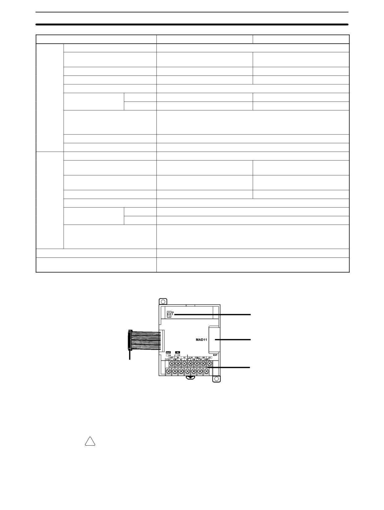
CPM1A-MAD11 Part Names
DIP switch
Expansion connector
Expansion I/O connecting cable
Analog I/O terminals
Analog I/O Terminals
Connected to analog I/O devices.
Expansion I/O
Connected to the CPU Unit or previous Expansion Unit. The cable is provided
Connecting Cable
with the Unit and cannot be removed.
!
Caution Do not touch the cables during operation. Static electricity may cause operating
errors.
Expansion Connector
Connected to the next Expansion Unit or Expansion I/O Unit.
174
Analog I/O Units
Section
3-1
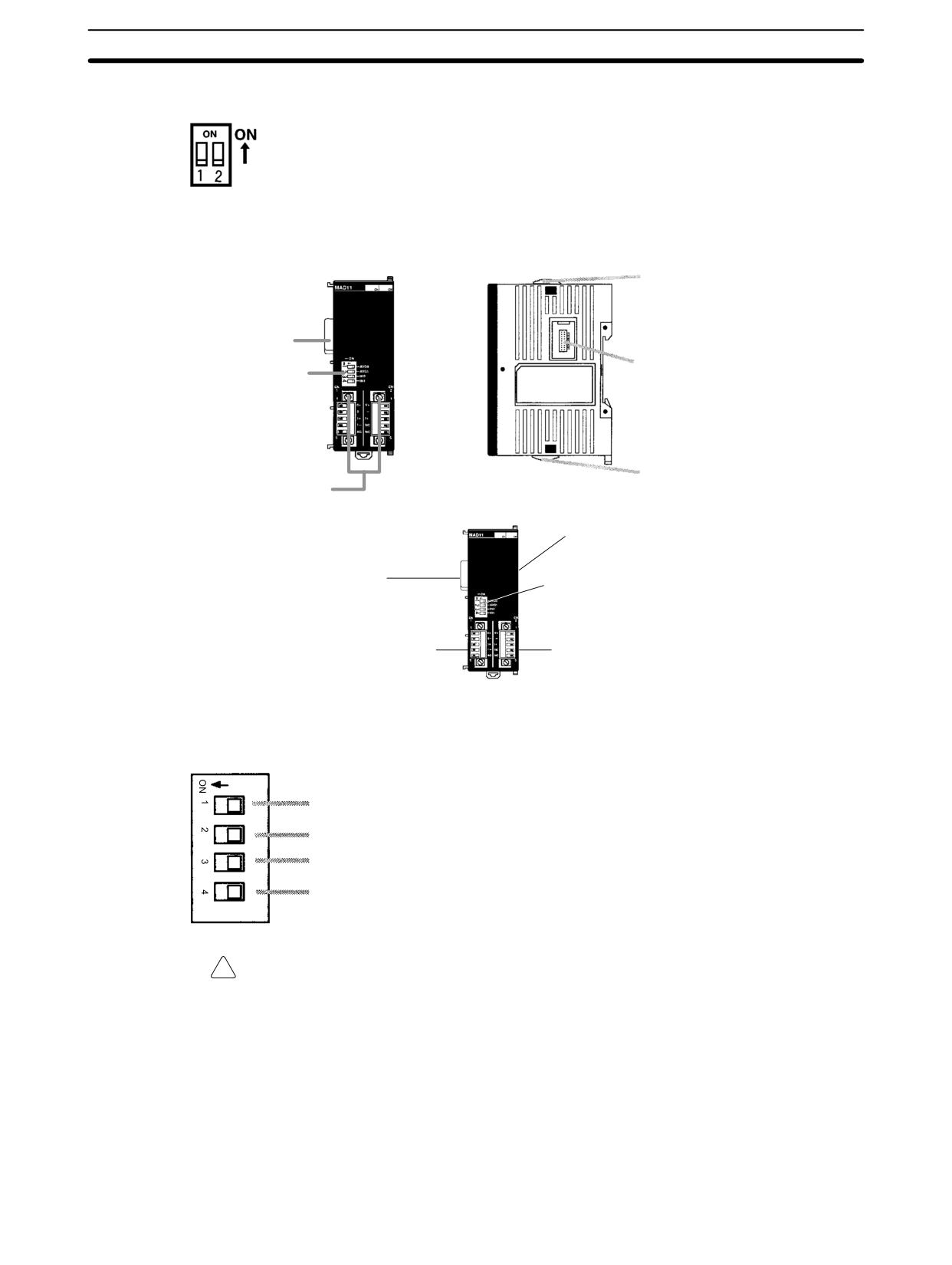
DIP Switch
Used to enable or disable averaging.
Pin1: Average processing for analog input 0
(OFF: Average processing not performed; ON: Average processing performed)
Pin2: Average processing for analog input 1
(OFF: Average processing not performed; ON: Average processing performed)
CPM2C-MAD11 Part Names
Front
Side
Lock level
Expansion I/O
input connector
Expansion I/O
DIP switch
output connector
Lock level
Analog I/O terminals
Expansion I/O output connector
Expansion I/O input connector
DIP switch
Analog input terminals
Analog output terminals
Analog I/O Terminals
Connected to analog I/O devices.
DIP Switch
Used to specify current or voltage inputs and to enable or disable averaging.
Average processing for analog input 0
(OFF: Average processing not performed; ON: Average processing performed)
Average processing for analog input 1
(OFF: Average processing not performed; ON: Average processing performed)
Input type for analog input 0
(OFF: Voltage input; ON: Current input)
Input type for analog input 1
(OFF: Voltage input; ON: Current input)
!
Caution Do not touch the DIP switch during operation. Static electricity may cause oper-
ating errors.
Expansion I/O Input
Connected to the expansion I/O output connector on the CPU Unit or previous
Connector
Expansion (I/O) Unit.
Expansion I/O Output
Connected to the expansion I/O input connector on the next Expansion (I/O)
Connector
Unit.
Note
1. A maximum of 5 Expansion (I/O) Units can be connected to the CPU Unit
and the total number of allocated words must be 10 maximum for inputs and
10 maximum for outputs.
175
Analog I/O Units
Section
3-1
2. Use the connector cover provided with the CPU Unit to protect the output
connector when it is not used.
!
Caution Do not touch the cables during operation. Static electricity may cause operating
errors.
Lock Levers
Used to secure the Expansion Unit.
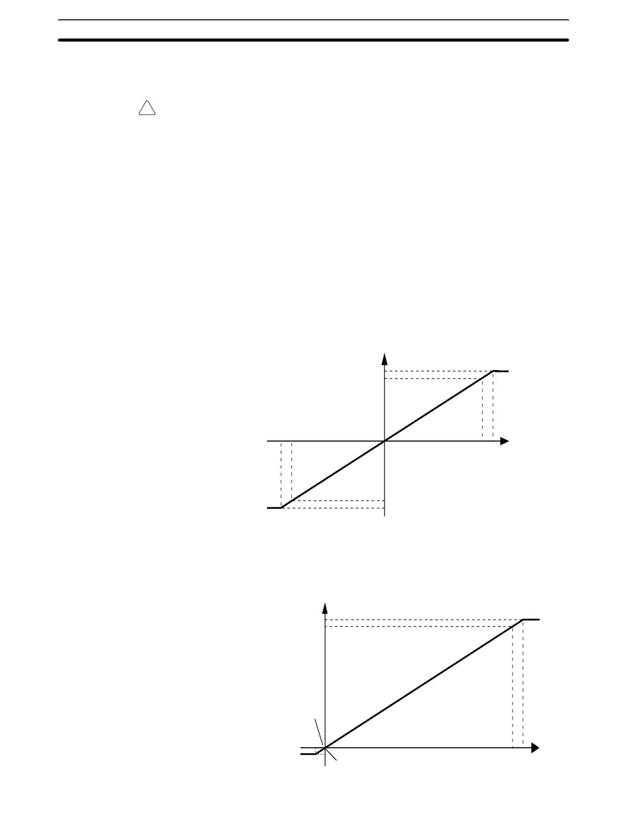
Analog I/O Signal Ranges
Analog I/O signal ranges are digitally converted as described in this section.
Analog Input Signal
The Analog I/O Unit converts analog input data to digital values. The digital val-
Ranges
ues depend on the input signal ranges, as shown in the following diagrams.
When the input exceeds the specified range, the AD converted data will be fixed
at either the lower limit or upper limit.
-10 to 10 V
The -10- to 10-V range corresponds to the hexadecimal values F448 to 0BB8
(-3000 to 3000). The entire data range is F31C to 0CE4 (-3300 to 3300). A neg-
ative voltage is expressed as a two’s complement.
Converted Data
Hexadecimal (Decimal)
0CE4 (3300)
0BB8 (3000)
-11 V -10 V
0000 (0)
0 V
10 V 11 V
F448 (-3000)
F31C (-3300)
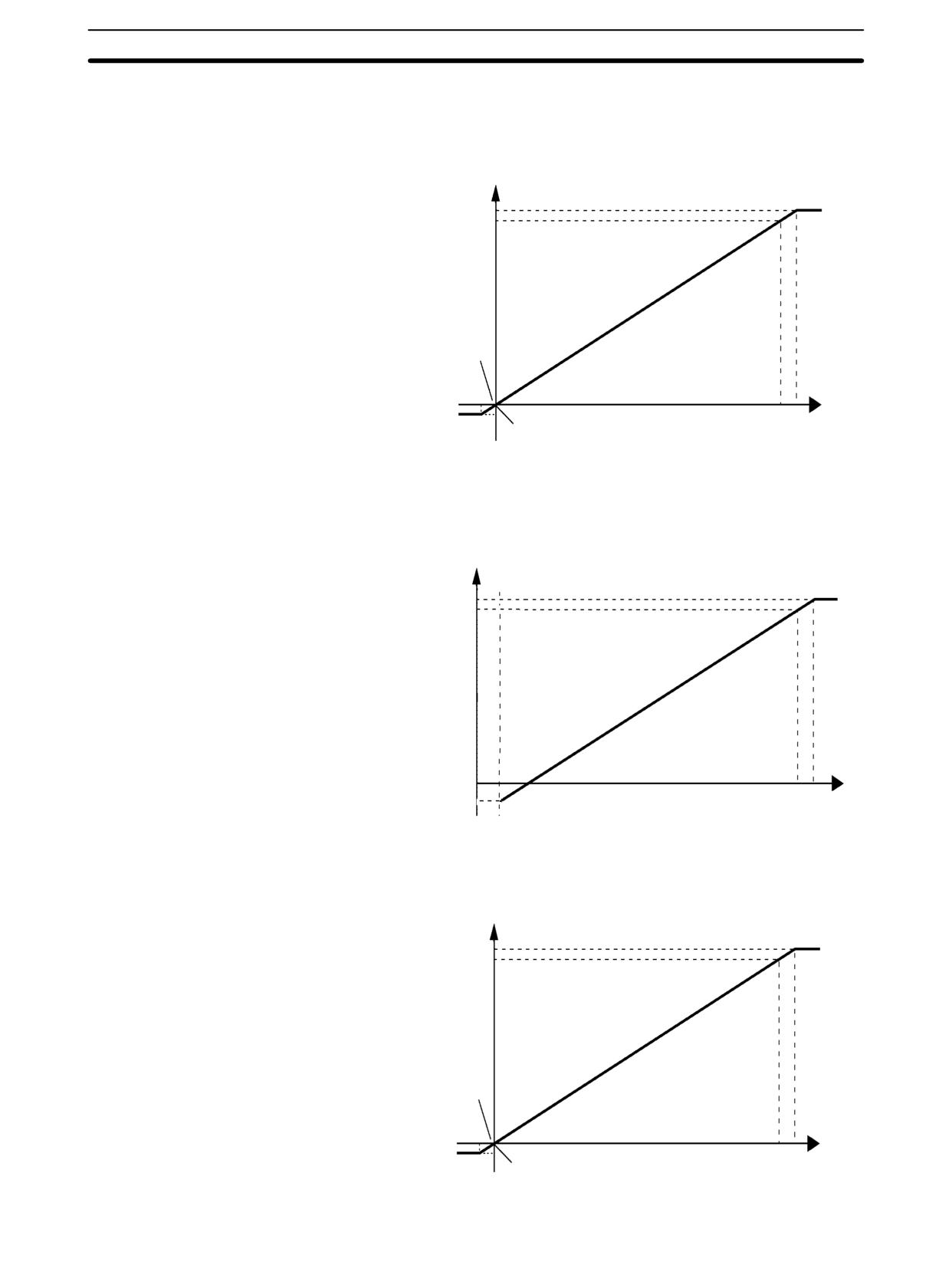
0 to 10 V
The 0- to 10-V range corresponds to the hexadecimal values 0000 to 1770 (0 to
6000). The entire data range is FED4 to 189C (-300 to 6300). A negative voltage
is expressed as a two’s complement.
Converted Data
Hexadecimal (Decimal)
189C (6300)
1770 (6000)
0000 (0)
-0.5 V
10 V 10.5 V
FED4 (-300)
0 V
176
Analog I/O Units
Section
3-1
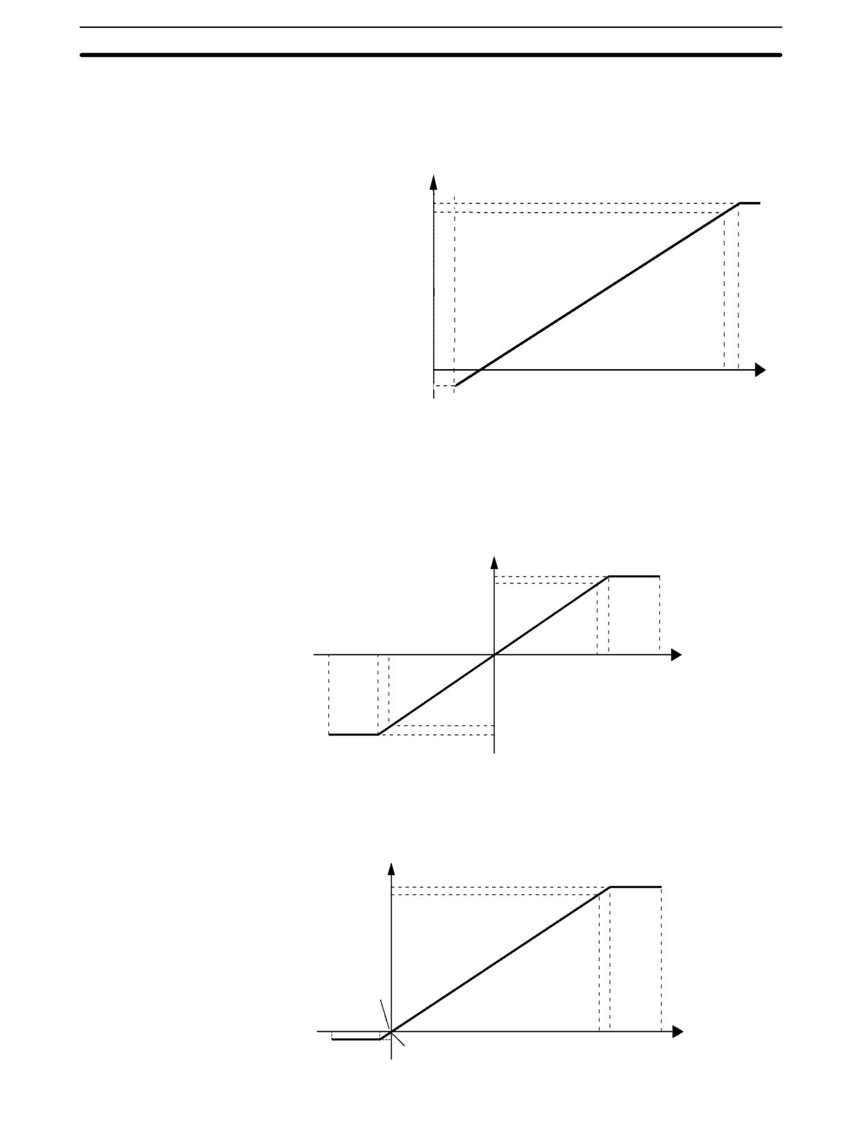
0 to 5 V
The 0- to 5-V range corresponds to the hexadecimal values 0000 to 1770 (0 to
6000). The entire data range is FED4 to 189C (-300 to 6300). A negative voltage
is expressed as a two’s complement.
Converted Data
Hexadecimal (Decimal)
189C (6300)
1770 (6000)
0000 (0)
-0.25 V
5 V 5.25 V
FED4 (-300)
0 V
1 to 5 V
The 1- to 5-V range corresponds to the hexadecimal values 0000 to 1770 (0 to
6000). The entire data range is FED4 to 189C (-300 to 6300). Inputs between
0.8 and 1 V are expressed as two’s complements. If the input falls below 0.8 V,
open-circuit detection will activate and converted data will be 8000.
Converted Data
Hexadecimal (Decimal)
189C (6300)
1770 (6000)
0.8 V
0000 (0)
FED4 (-300)
1 V
5 V
5.2 V
0 to 20 mA
The 0- to 20-mA range corresponds to the hexadecimal values 0000 to 1770 (0
to 6000). The entire data range is FED4 to 189C (-300 to 6300). A negative volt-
age is expressed as a two’s complement.
Converted Data
Hexadecimal (Decimal)
189C (6300)
1770 (6000)
0000 (0)
-1 mA
20 mA 21 mA
FED4 (-300)
0 mA
177
Analog I/O Units
Section
3-1
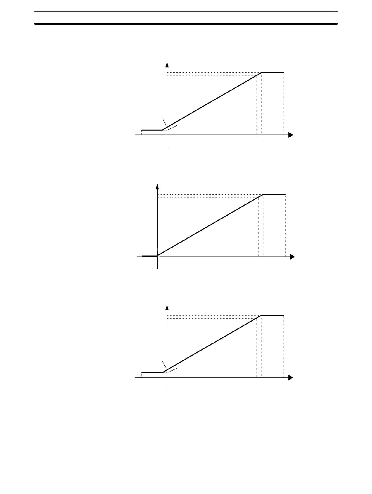
4 to 20 mA
The 4- to 20-mA range corresponds to the hexadecimal values 0000 to 1770 (0
to 6000). The entire data range is FED4 to 189C (-300 to 6300). Inputs between
3.2 and 4 mA are expressed as two’s complements. If the input falls below
3.2 mA, open-circuit detection will activate and converted data will be 8000.
Converted Data
Hexadecimal (Decimal)
189C (6300)
1770 (6000)
3.2 mA
0000 (0)
4 mA
20 mA 20.8 mA
FED4 (-300)
0 mA
Analog Output Signal
The Analog I/O Unit converts the digital output data to analog values. The analog
Ranges
values depend on the output signal ranges, as shown in the following diagrams.
-10 to 10 V
The hexadecimal values F448 to 0BB8 (-3000 to 3000) correspond to an analog
voltage range of -10 to 10 V. The entire output range is -11 to 11 V. Specify a
negative voltage as a two’s complement.
11 V
10 V
F31C
F448
(-3300) (-3000)
Conversion
8000
0000 (0)
Data
0BB8 0CE4
Hexadecimal
0 V
7FFF
(3000) (3300)
(Decimal)
-10 V
-11 V
0 to 10 V
The hexadecimal values 0000 to 1770 (0 to 6000) correspond to an analog volt-
age range of 0 to 10 V. The entire output range is -0.5 to 10.5 V. Specify a nega-
tive voltage as a two’s complement.
10.5 V
10 V
0 V
(-300)
Conversion
Data
8000 FED4
Hexadecimal
1770
189C
0000 (0)
7FFF
(Decimal)
-0.5 V
(6000)
(6300)
178
Analog I/O Units
Section
3-1
1 to 5 V
The hexadecimal values 0000 to 1770 (0 to 6000) correspond to an analog volt-
age range of 1 to 5 V. The entire output range is 0.8 to 5.2 V.
5.2 V
5 V
1 V
0.8 V
Conversion
0 V
Data
Hexadecimal
FED4
1770
189C
8000
0000 (0)
(Decimal)
7FFF
(-300)
(6000)
(6300)
0 to 20 mA
The hexadecimal values 0000 to 1770 (0 to 6000) correspond to an analog cur-
rent range of 0 to 20 mA. The entire output range is 0 to 21 mA.
21 mA
20 mA
0000
(0)
Conversion
Data
8000
0 mA
1770
189C
Hexadecimal
7FFF
(6000)
(6300)
(Decimal)
4 to 20 mA
The hexadecimal values 0000 to 1770 (0 to 6000) correspond to an analog cur-
rent range of 4 to 20 mA. The entire output range is 3.2 to 20.8 mA.
20.8 mA
20 mA
4 mA
3.2 mA
Conversion
0 mA
Data
Hexadecimal
FED4
1770
189C
8000
0000 (0)
7FFF
(Decimal)
(-300)
(6000)
(6300)
Averaging Function for
The averaging function can be enabled for inputs using the DIP switch. The
Analog Inputs
averaging function stores the average (a moving average) of the last eight input
values as the converted value. Use this function to smooth inputs that vary at a
short interval.
Open-circuit Detection
The open-circuit detection function is activated when the input range is set to 1 to
Function for Analog
5 V and the voltage drops below 0.8 V, or when the input range is set to 4 to
Inputs
20 mA and the current drops below 3.2 mA. When the open-circuit detection
function is activated, the converted data will be set to 8000.
179
Analog I/O Units
Section
3-1
The open-circuit detection function is enabled or cleared when data is con-
verted. If the input returns to the convertible range, the open-circuit detection is
cleared automatically and the output returns to the normal range.
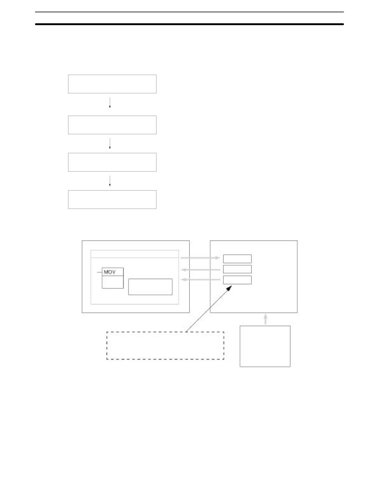
Using Analog I/O
Connect the Unit.
Connect the Analog I/O Unit.
Analog inputs:
0 to 5 VDC, 1 to 5 VDC, 0 to 10 VDC,
-10 to 10 VDC, 0 to 20 mA, or 4 to 20 mA
Set the I/O ranges.
Analog output:
1 to 5 VDC, 0 to 10 VDC, -10 to 10 VDC,
0 to 20 mA, or 4 to 20 mA
Set inputs as voltage or analog and set the averaging function.
Wire the analog I/O.
Connect analog I/O devices.
Write the range code.
Program operation in the
ladder program.
Analog inputs: Read converted data.
Analog output: Write set values.
Analog Inputs
CPU Unit
Analog I/O Unit
Ladder program
Word (n + 1)
Range code
Word (m + 1)
Analog input 0
(21)
MOVE instruction
converted value
Word (m + 2)
Analog input 1
Writes the range code.
converted value
Reads the converted
values.
Analog devices
Temperature sensor
Where “m” is the last input word and “n” is the
Pressure sensor
Speed sensor
last output word allocated to the CPU Unit, or
Flow sensor
previous Expansion Unit or Expansion I/O Unit.
Voltage/current meter
Other
180
Analog I/O Units
Section
3-1
Analog Outputs
CPU Unit
Analog I/O Unit
Ladder program
(See note.)
Word (n + 1)
Range code
Analog output set value
(21) MOVE instruction
Writes the range code.
Writes the set value.
Analog devices
Adjustment equipment
Where “n” is the last output word allocated to
Servo Controller
the CPU Unit, or previous Expansion Unit or
Variable speed device
Expansion I/O Unit.
Recorder
Other
Note Word (n + 1) can be used for either the range code or the analog output set value.
This section describes how to connect an Analog I/O Unit to the CPU Unit.
Connecting the
CPM1A-MAD11 Analog
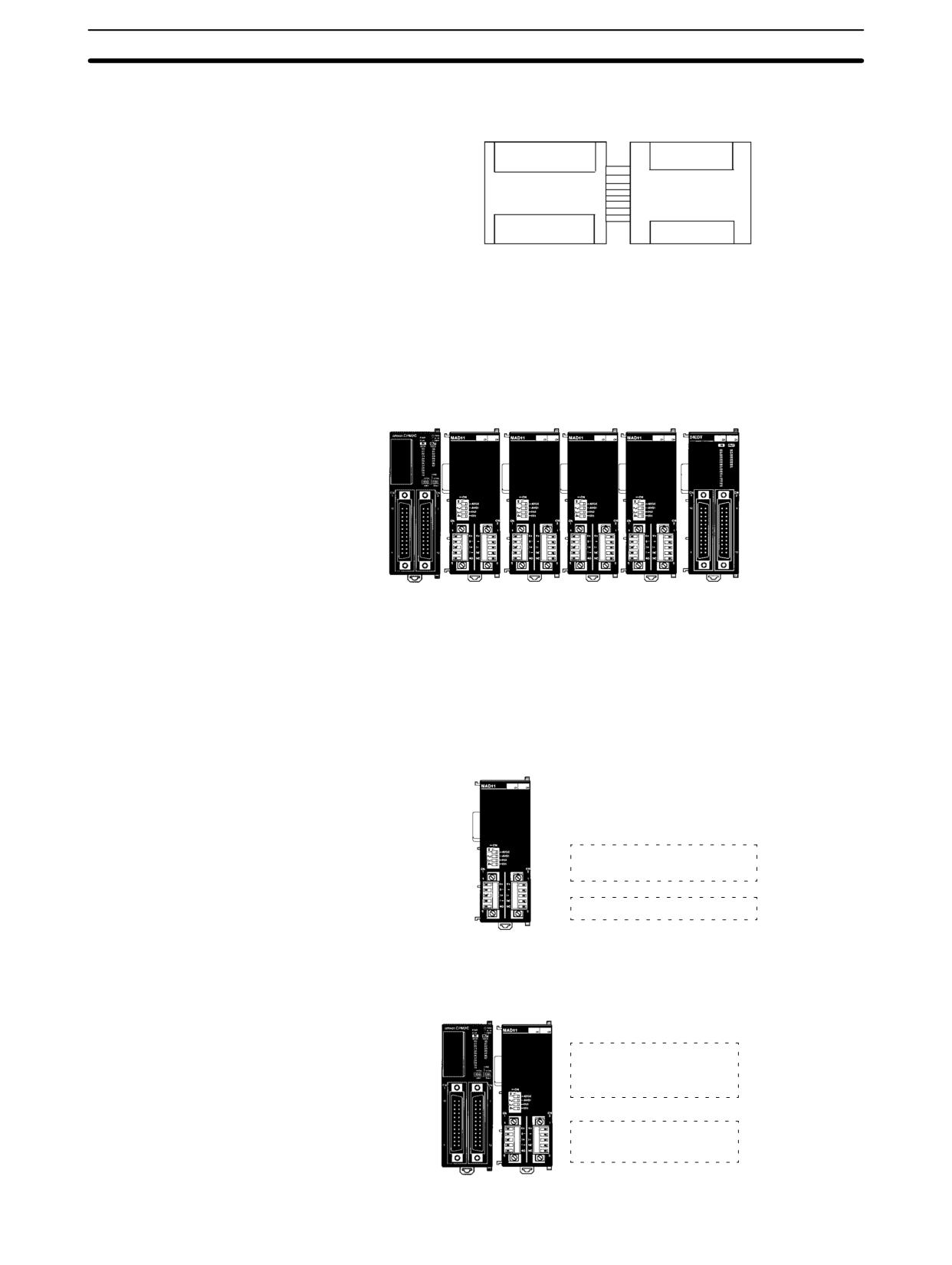
A maximum of 3 Expansion Units or Expansion I/O Units, including up to 3 Ana-
I/O Unit
log I/O Units, can be connected to one CPM2A or CPM1A PC. When the Analog
I/O Unit is used in combination with other Expansion Units or Expansion I/O
Units, there are no restrictions on the connection order.
CPM1A/CPM2A
CPM1A-MAD11
CPU Unit
Analog I/O Unit
I/O Allocation
I/O is allocated for the Analog I/O Unit in the same way as other Expansion Units
or Expansion I/O Units starting from the next word following the last allocated
word on the CPU Unit or previous Expansion Unit or Expansion I/O Unit. When
“m” is the last allocated input word and “n” the last allocated output word on the
CPU Unit, or previous Expansion Unit or Expansion I/O Unit, the allocation will
be as follows:
CPM1A-MAD11
Analog I/O Unit
Analog input 0: Word m+1
Analog input 1: Word m+2
32 inputs
16 outputs
Analog output: Word n+1
181
Analog I/O Units
Section
3-1
For example, in the following diagram an Analog I/O Unit is connected to a CPU
Unit with 30 I/O points.
IR 000
IR 002
Inputs
IR 001
IR 003
30-point
CPM1A-MAD11
CPU Unit
Analog I/O Unit
IR 010
Outputs
IR 011
IR 012
This section describes how to connect an Analog I/O Unit to the CPU Unit.
Connecting the
CPM2C-MAD11 Analog
A maximum of 5 Expansion Units or Expansion I/O Units (a maximum of 3 Units
I/O Unit
for the CPM2C-S), including up to 4 Analog I/O Units, can be connected to one
CPM2C PC. When the Analog I/O Unit is used in combination with other Expan-
sion Units or Expansion I/O Units, there are no restrictions on the connection
order.
CPU Unit
CPM2C-MAD11 Analog I/O Units
Expansion I/O Unit
I/O Allocation
I/O is allocated for the Analog I/O Unit in the same way as other Expansion Units
or Expansion I/O Units starting from the next word following the last allocated
word on the CPU Unit or previous Expansion Unit or Expansion I/O Unit. When
“m” is the last allocated input word and “n” the last allocated output word on the
CPU Unit, or previous Expansion Unit or Expansion I/O Unit, the allocation will
be as follows:
CPM2C-MAD11 Analog I/O Unit
Analog input 0:
Word m+1
Analog input 1:
Word m+2
Analog output:
Word n+1
For example, in the following diagram an Analog I/O Unit is connected to a CPU
Unit with 20 I/O points.
CPU Unit CPM2C-MAD11 Analog I/O Unit
CPU Unit inputs:
IR 000
Analog input 0:
IR 001
Analog input 1:
IR 002
CPU Unit outputs: IR 010
Analog output:
IR 011
182
Analog I/O Units
Section
3-1
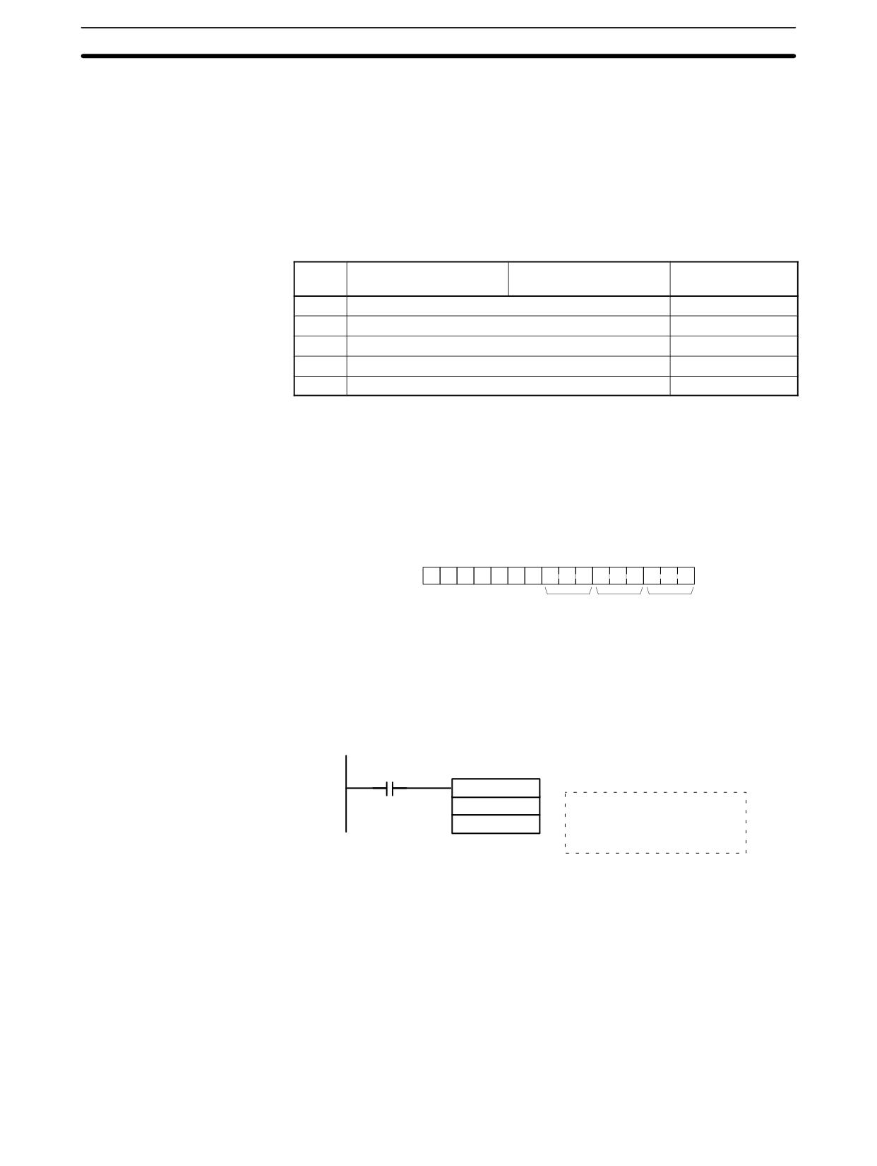
I/O signal ranges are set by writing a range code to the output word of the Analog
Setting I/O Signal Range
I/O Unit. The range code must be set for the Analog I/O Unit to convert data.
The range code settings provide the combinations of signal ranges for the ana-
log inputs and analog output, as shown in the following table.
Voltage/current selections for the CPM1A-MAD11 are made by connecting the
appropriate terminals. Refer to page 184 for details.
Voltage/current selections for the CPM2C-MAD11 are made using pins 3 and 4
on the DIP switch. refer to page 175 for details.
Range
Analog input 1
Analog input 2
Analog output
code
signal range
signal range
signal range
000
-10 to 10 V
-10 to 10 V
001
0 to 10 V
0 to 10 V
010
1 to 5 V or 4 to 20 mA
1 to 5 V
011
1 to 5 V or 0 to 20 mA
0 to 20 mA
100
---
4 to 20 mA
Note
Be sure to write the correct terminals or set the DIP switch to specify either volt-
age or current inputs.
Write the range codes to the Analog I/O Unit’s output word (n + 1) in the first cycle
of program execution.
15
8
7
6
5
4
3
2
1
0
n+1
1
0
0
0
0
0
0
Analog Analog Analog
output
input 0
input 1
Example
The following instructions set analog input 0 to 4 to 20 mA, analog input 1 to 0 to
10 V, and the analog output to -10 to 10 V.
SR 25315
(First Cycle Flag)
MOV (21)
#800A
Analog input 0:
4 to 20 mA
011
Analog input 1:
0 to 10 V
Analog output:
-10 to 10 V
The Analog I/O Unit will not start converting analog I/O values until the range
code has been written. Until conversion starts, inputs will be 0000, and 0 V or
0 mA will be output.
After the range code has been set, 0 V or 0 mA will be output for the 0 to 10-V,
-10 to 10-V, or 0 to 20-mA ranges, and 1 V or 4 mA will be output for the 1 to 5-V
and 4 to 20-mA ranges until a convertible value has been written to the output
word.
Once the range code has been set, it is not possible to change the setting while
power is being supplied to the CPU Unit. To change the I/O range, turn the CPU
Unit OFF then ON again.
183
Analog I/O Units
Section
3-1
Wiring Analog I/O Devices
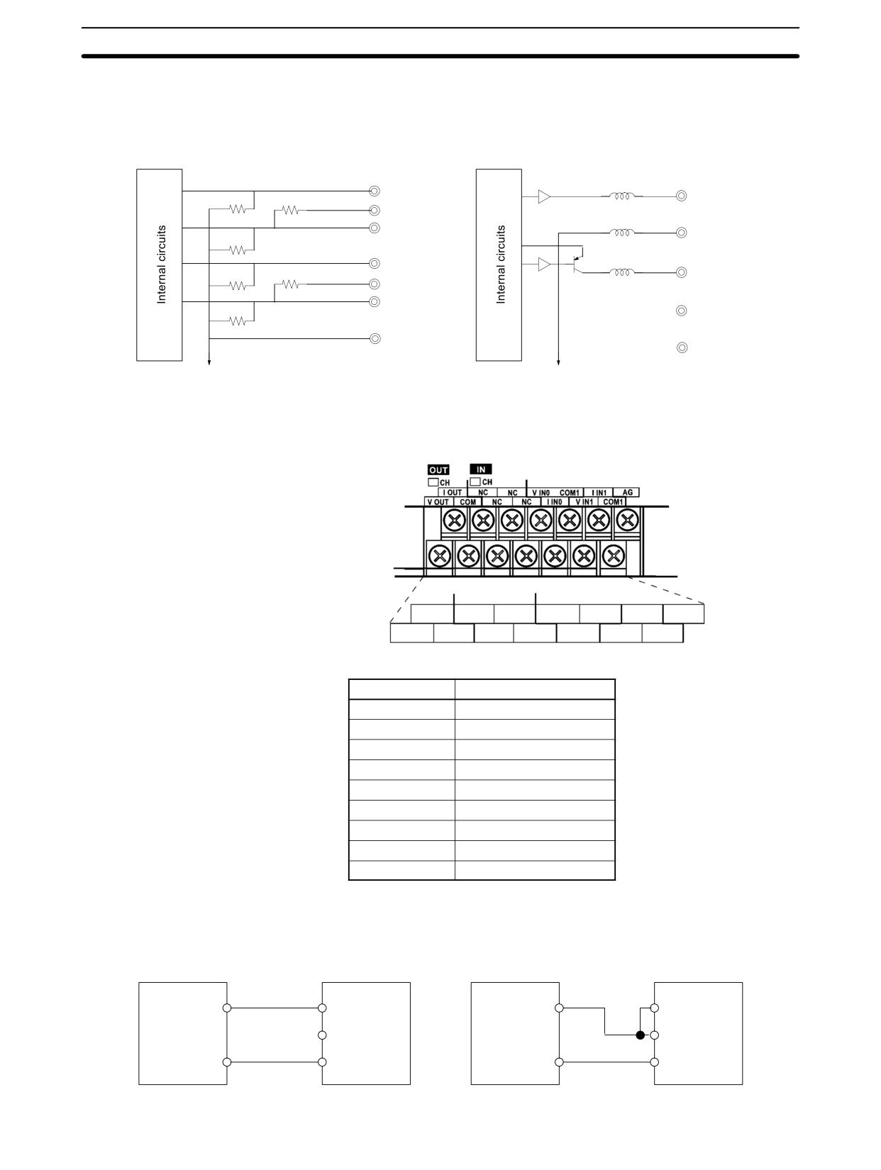
CPM1A-MAD11 Internal Circuits
Analog Inputs
Analog Outputs
Input 0
Output
510 kΩ
V IN -
V OUT
I IN 0
250 Ω
COM 0 (-)
COM (-)
510 kΩ
Input 1
V IN 1
510 kΩ
I OUT
I IN 1
250 Ω
COM 1 (-)
510 kΩ
NC
AG
NC
Analog ground
Analog ground
CPM1A-MAD11 Terminal Arrangements
I OUT NC
NC
V IN0
COM0 I IN1
AG
V OUT COM NC
NC
I IN0
V IN0
COM1
Label
Signal
V OUT
Voltage output
I OUT
Current output
COM
Output common
V IN0
Voltage input 0
I IN0
Current input 0
COM0
Input common 0
V IN1
Voltage input 1
I IN1
Current input 1
COM1
Input common 1
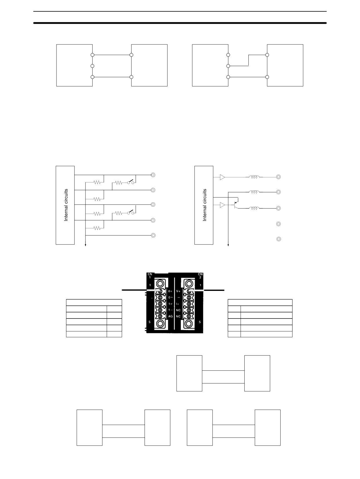
Note For current inputs, short V IN0 to I IN0 and V IN1 to I IN1
Wiring for Analog Inputs
+
V IN
+
V IN
Analog device
Analog
Analog
Analog device
I IN
with voltage
I IN
I/O
I/O
with current
output
Unit
Unit
–
output
–
COM
COM
184
Analog I/O Units
Section
3-1
Wiring for Analog Outputs
V OUT
+
V OUT
+
Analog
Analog device
Analog
Analog device
I/O
I OUT
with voltage
I/O
I OUT
with current
Unit
input
Unit
input
COM
–
COM
–
Note
1. Use shielded twisted-pair cables, but do not connect the shield.
2. When an input is not being used, short the + and - terminals.
3. Separate wiring from power lines (AC power supply lines, high-voltage
lines, etc.)
4. When there is noise in the power supply line, install a noise filter on the input
section and the Power Supply Unit.
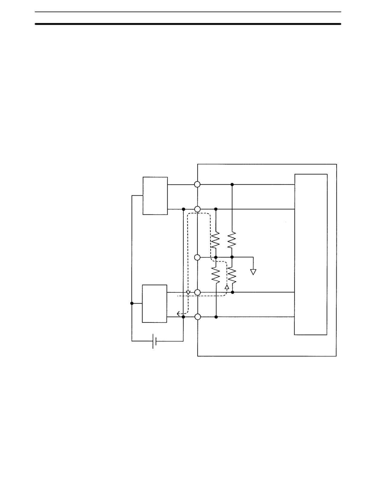
CPM2C-MAD11 Internal Circuits
Analog Inputs
Analog Outputs
510 kΩ
0+
V+
Input 0
250 Ω
0-
- Output
510 kΩ
1+
510 kΩ
I+
Input 1
250 Ω
1+
510 kΩ
NC
AG
NC
Analog ground
Analog ground
CPM2C-MAD11 Terminal Arrangements
Analog Input Terminals
Analog Output Terminals
IN
OUT
Analog input 0 +
0 +
V+
Analog voltage output
Analog input 0 -
0 -
-
Output common
Analog input 1 +
1 +
I+
Analog current output
Analog input 1 -
1 -
NC
Not used
Analog ground
AG
NC
Not used
Analog Input Wiring
Analog
+
+
Analog
output
I/O Unit
device
-
-
Analog Output Wiring
Analog
V+
+
I+
+ Analog
Analog
input device
Analog
input device
I/O Unit
with voltage
I/O Unit
with current
–
-
input
–
-
input
185
Analog I/O Units
Section
3-1
Note
1. Use shielded twisted-pair cables, but do not connect the shield.
2. When an input is not being used, short the + and - terminals.
3. Separate wiring from power lines (AC power supply lines, high-voltage
lines, etc.)
4. When there is noise in the power supply line, install a noise filter on the input
section and the Power Supply Unit.
Reference Information
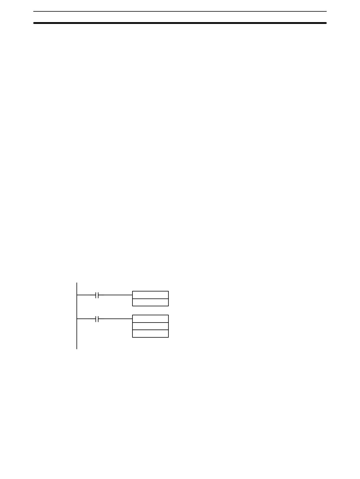
Consider the following information on open input circuits when using voltage in-
puts.
If the same power supply is used as shown in the following diagram and an open
circuit occurs at point A or B, an unwanted current flow will occur as shown by the
dotted lines in the diagram, creating a voltage at the other input of about 1/3 to
1/2. If the 1 to 5-V range is being used, the open-circuit detection function will not
operate. Also, if there is an open circuit at C, the open-circuit detection function
will not operate because the negative sides are the same.
A
Analog
input
device 1
B
C
Analog
input
device 2
24 VDC
For example, if analog input device 2 is outputting 5 V and the same power sup-
ply is being used as shown above, about 1/3, or 1.6 V, will be applied at the input
for input device 1.
To eliminate the above problem, either use separate power supplies, or install an
isolator at each input. This problem will not occur for current inputs even if the
same power supply is used.
Note When power is supplied (when setting the range code), or when there is a power
interruption, pulse-form analog output of up to 1 ms may be generated.
If this causes problems with operation, take countermeasure such as those sug-
gested below.
• Turn ON the power supply for the CPU Unit first, and then turn ON the power
supply for the load after confirming correct operation.
186
Analog I/O Units
Section
3-1
• Turn OFF the power supply for the load before turning OFF the power supply
for the CPU Unit.
Ladder Program
Specifying the Range Code
Specify the I/O signal range by writing the range code to the Analog I/O Unit’s
output word from the ladder program in the first cycle of program execution. The
Analog I/O Unit will start to convert analog I/O values once the range code has
been specified and convertible values are provided. (Refer to page NO TAG.)
Write the range code to the Analog I/O Unit’s output word in the first cycle of op-
eration; the Analog I/O Unit’s output word is “n+1” when “n” is the last word allo-
cated to the CPU Unit, or previous Expansion Unit or Expansion I/O Unit in the
configuration.
Reading Converted Analog Input Values
The ladder program can be used to read the memory area where the converted
values are stored. Values are output to the next two words (m + 1, m + 2) follow-
ing the last input word (m) allocated to the CPU Unit or previous Expansion Unit
or Expansion I/O Unit.
Writing Analog Output Set Values
The ladder program can be used to write data to the output word where the set
value is stored. The output word will be “n+1” when “n” is the last output word
allocated to the CPU Unit, or previous Expansion Unit or Expansion I/O Unit.
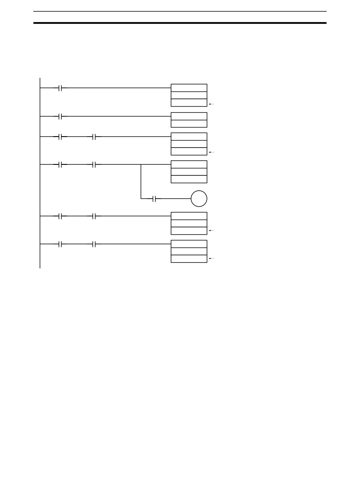
Startup Operation
After power is turned ON, it will require two cycle times plus approx. 50 ms before
the first data is converted. The following instructions can be placed at the begin-
ning of the program to delay reading converted data from analog inputs until con-
version is actually possible.
Note Analog input data will be 0000 until initial processing has been completed. Ana-
log output data will be 0 V or 0 mA until the range code has been written. After the
range code has been written, the analog output data will be 0 V or 0 mA if the
range is 0 to 10 V, -10 to 10 V, or 0 to 20 mA, or it will be 1 V or 4 mA if the range is
1 to 5 V or 4 to 20 mA.
SR 25315
(Always ON Flag)
TIM 005
TIM 005 will start as soon as power turns ON.
#0002
After 0.1 to 0.2 s (100 to 200 ms), the Comple-
T005
tion Flag for TIM 005 will turn ON, and the con-
verted data from analog input will be read from
MOV (21)
IR 001 and stored in DM 0000.
001
DM0000
Handling Unit Errors
If an error occurs in an Analog I/O Unit, the Error Flags in AR 0200 to AR 0204 for
the CPM2C and AR 0200 to AR 0202 for the CPM1A/CPM2A will be turned ON.
The addresses of the Error Flags are in the order that the Expansion Units and
Expansion I/O Units are connected in the PC, with AR 0200 used for the Expan-
sion Unit or Expansion I/O Unit closest to the CPU Unit. Use these flags in the
program when it is necessary to detect errors.
When an error occurs in the Analog I/O Unit, analog input data will be 0000 and
0 V or 0 mA will be output as the analog output.
If a CPU error or an I/O bus error (fatal errors) occurs at the CPU Unit and the
analog output is set to 1 to 5 V or 4 to 20 mA, 0 V or 0 mA will be output. For any
other fatal errors at the CPU Unit, 1 V or 4 mA will be output.
187
Analog I/O Units
Section
3-1
Programming Example
This programming example uses these ranges:
Analog input 0: 0 to 10 V
Analog input 1: 4 to 20 mA
Analog output:
0 to 10 V
25135
(First Cycle ON Flag)
MOV (21)
8051
011
25313
Writes the range code (8051) to the Unit.
(Always ON Flag)
TIM 005
#0002
Execution
TIM005
condition
MOV (21)
001
DM0000
Execution
Reads analog input 0’s converted value.
TIM005
condition
CMP (20)
002
#8000
25506(=)
01000
Open-circuit alarm
Execution
TIM005
condition
MOV (21)
002
DM0001
Reads analog input 1’s converted value.
Execution
TIM005
condition
MOV (21)
DM0010
011
The content of DM 0010 is written to the output
word as the analog output set value.
188
Temperature Sensor Units
Section
3-2
3-2
Temperature Sensor Units
3-2-1
CPM1A/CPM2A Temperature Sensor Units
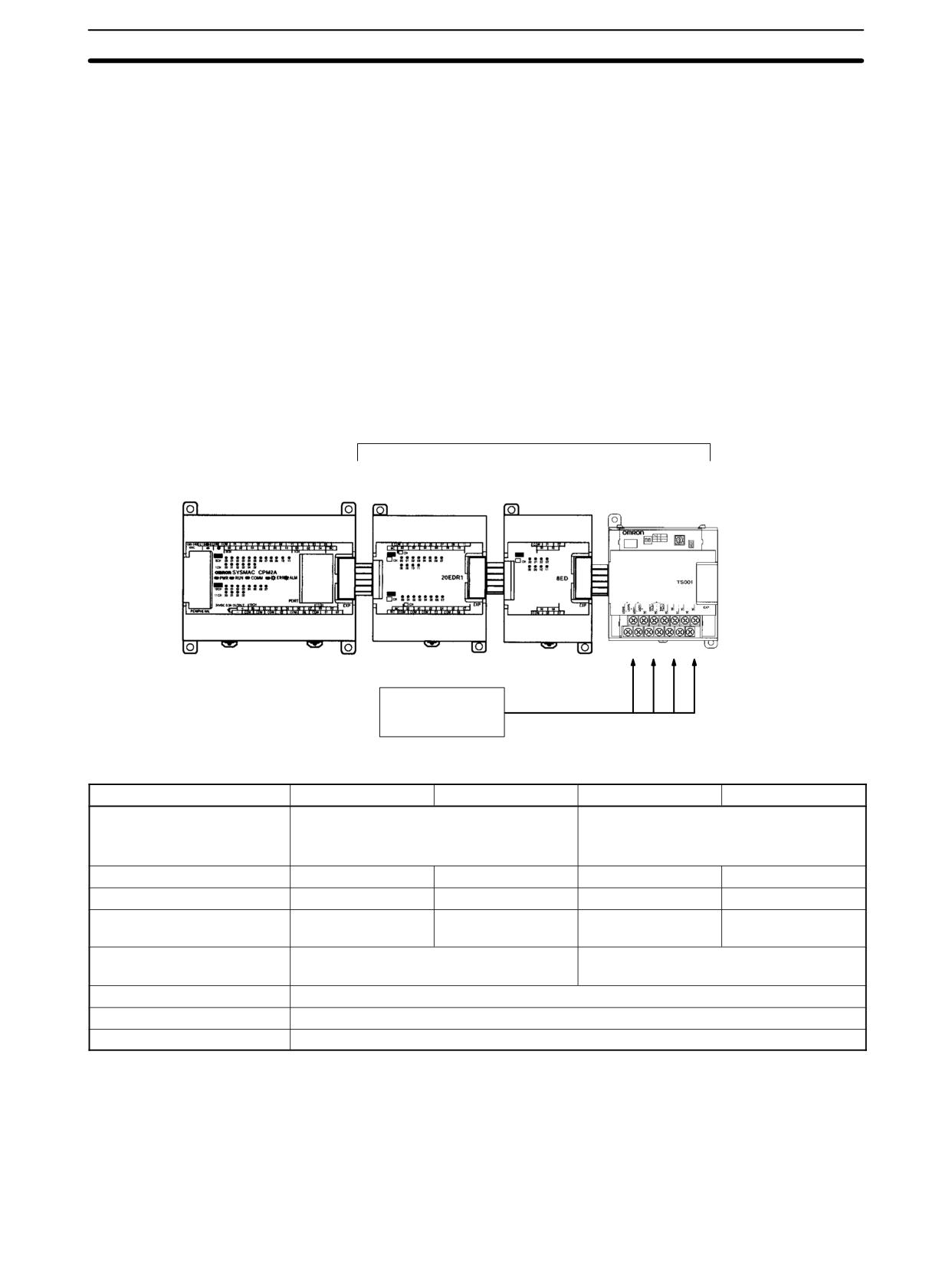
With the CPM1A or CPM2A, up to three Expansion Units or Expansion I/O Units
can be connected to the CPU Unit. One, two, or three of these Units can be
CPM1A-TS001 or CPM1A-TS101 Temperature Sensor Units. If a CPM1A-
TS002 or CPM1A-TS102 Temperature Sensor Unit is connected to the CPU
Unit, then only one other Expansion Unit or Expansion I/O Unit can be con-
nected. The other Unit can be a CPM1A-TS001/TS101 Temperature Sensor
Unit.
The CPM1A-TS001/TS101 Temperature Sensor Units each provide 2 input
points and the CPM1A-TS002/TS102 Temperature Sensor Units each provide 4
input points, meaning up to 6 temperature input points can be used on one
CPM1A or CPM2A PC. The inputs can be from thermocouples or platinum resis-
tance thermometers.
Up to 3 Units, including Expansion I/O Units and other Expansion
Units. (Only 2 Units if CPM1A-TS002/TS102 is used.)
CPM1A-20EDR1
CPM1A-8ED
CPM1A-TSjjj
CPM1A or CPM2A CPU Unit
Expansion I/O Unit Expansion I/O Unit Temperature Sensor Unit
Thermocouples or
platinum resistance
thermometers
Temperature inputs
Specifications
Item
CPM1A-TS001
CPM1A-TS002
CPM1A-TS101
CPM1A-TS102
Temperature sensors
Thermocouples
Platinum resistance thermometer
Switchable between K and J, but same
Switchable between Pt100 and JPt100, but
type must be used for all inputs.
same type must be used for all inputs.
Number of inputs
2
4
2
4
Allocated input words
2
4
2
4
Max. number of Units
3
1
3
1
(See note 1.)
Accuracy
(The larger of ±0.5% of converted value or
(The larger of ±0.5% of converted value or
±2_C) ±1 digit max. (See note 2.)
±1_C) ±1 digit max.
Conversion time
250 ms for 2 or 4 input points
Converted temperature data
16-bit binary data (4-digit hexadecimal)
Isolation
Photocouplers between all temperature input signals
Note
1. If only the CPM1A-TS001 and CPM1A-TS101 are connected, then up to 3
Units including Expansion I/O Units and other Expansion Units can be con-
nected. If the CPM1A-TS002 or CPM1A-TS102 is connected, then only one
other Expansion I/O Unit or Expansion Unit can be connected. The CPM1A-
TS001 or CPM1A-TS101 may be the other Unit, but another CPM1A-TS002
or CPM1A-TS102 cannot be connected.
189
Temperature Sensor Units
Section
3-2
2. Accuracy for a K-type sensor at -100°C or less is ±4_C ±1 digit max.
3-2-2
CPM2C Temperature Sensor Units
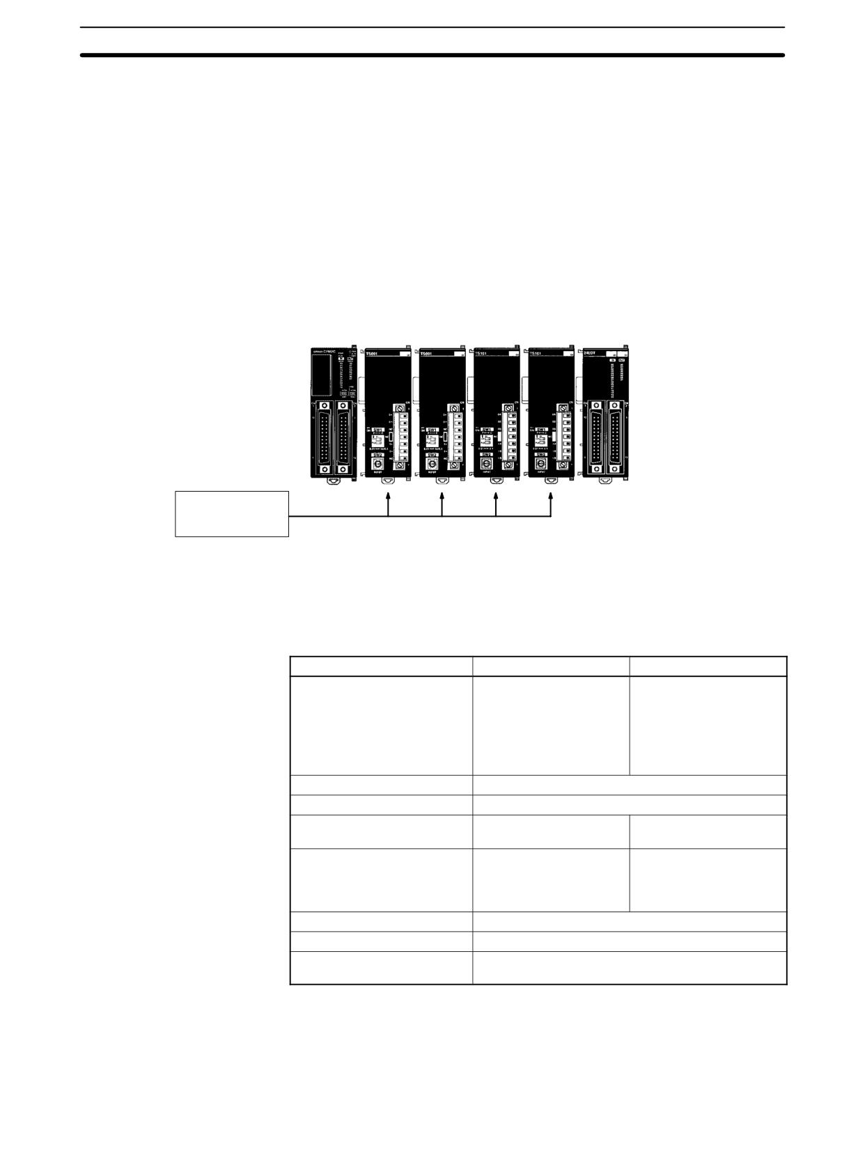
With the CPM2C (including the CPM2C-S), up to four CPM2C-TS001/TS101
Temperature Sensor Units can be connected (up to three Units for the
CPM2C-S). Each Temperature Sensor Unit provides 2 input points meaning that
a total of 8 input points can be used. The inputs can be from thermocouples or
platinum resistance thermometers.
CPM2C-TS001/101
CPM2C CPU Unit
Temperature Sensor Units
Expansion I/O Unit
Thermocouples or
platinum resistance
thermometers
Temperature inputs
8 points max.
Specifications
Item
CPM2C-TS001
CPM2C-TS101
Temperature sensors
Thermocouples
Platinum resistance
thermometer
Switchable between K
and J, but same type
Switchable between
must be used for all
Pt100 and JPt100, but
inputs.
same type must be used
for all inputs.
Number of inputs
2
Allocated input words
2
Max. number of Units
4
4
(See note 1.)
Accuracy
(The larger of ±0.5% of
(The larger of ±0.5% of
converted value or
converted value or
±2_C) ±1 digit max. (See
±1_C) ±1 digit max.
note.)
Conversion time
250 ms for 2 input points
Converted temperature data
16-bit binary data (4-digit hexadecimal)
Isolation
Photocouplers between all temperature input
signals
Note
1. Accuracy for a K-type sensor at -100°C or less is ±4_C ±1 digit max.
2. The error deviation for temperatures in °F is double that for °C.
190
Temperature Sensor Units
Section
3-2
3-2-3
Using Temperature Sensor Units
Connect the Unit.
Connect the Temperature Sensor Unit.
Refer to 3-2-4 Connecting Temperature Sensor Units.
Set the temperature unit, 2-decimal-place Mode if
required, and set the temperature input range.
Set the temperature ranges.
Refer to 3-2-5 Setting Temperature Ranges.
Connect the temperature sensors.
Connect temperature sensors.
Refer to 3-2-6 Connecting Temperature Sensors.
Read temperature data stored in the input word.
Program operation in the
Refer to 3-2-7 Ladder Programming.
ladder program.
3-2-4
Connecting Temperature Sensor Units
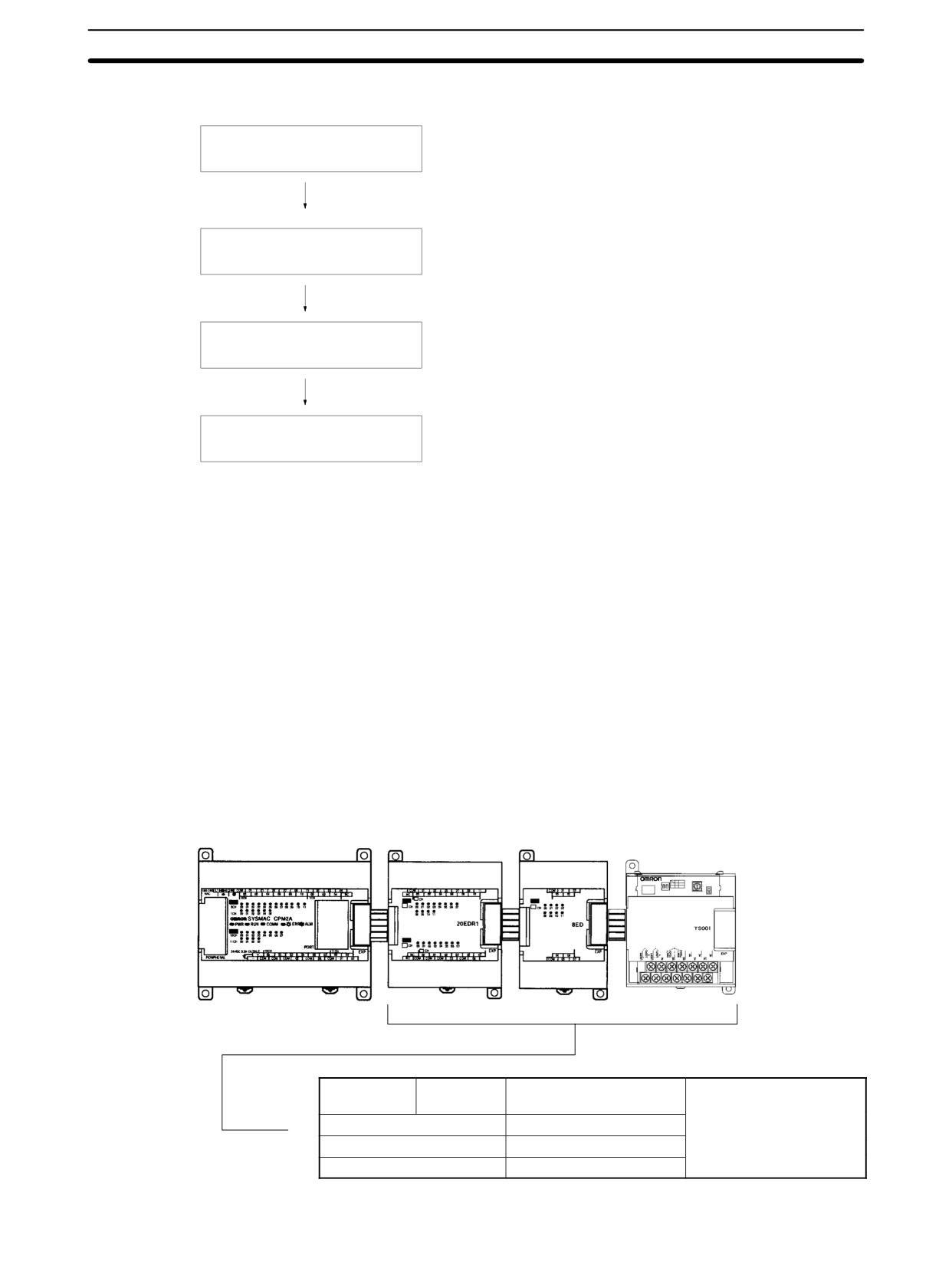
This section shows example configurations containing Temperature Sensor
Units.
CPM1A/CPM2A Temperature Sensor Unit Allocations
Words are allocated to Temperature Sensor Units just like other Expansion I/O
Units and Expansion Units: In the order in which the Units are connected. A Tem-
perature Sensor Unit will thus be allocated the next input words after the Unit to
which it is connected (CPU Unit or other Unit).
Note Only one 4-input Temperature Sensor Unit (CPM1A-TS002 or CPM1A-TS102,
4 words allocated) can be mounted to the CPU Unit. There are, however, no
restrictions on the mounting order.
Temperature Sensor Units with 2 Inputs: CPM1A-TS001 and CPM1A-TS101 (2 Words Allocated)
CPM1A or CPM2A CPU Unit
CPM1A-20EDR1
CPM1A-8ED
CPM1A-TS001/TS101
(with 20, 30, 40, or 60 I/O points) Expansion I/O Unit Expansion I/O Unit Temperature Sensor Unit
Temperature
2 inputs
CPM1A-TS001
Up to 3 Units can be
Sensor Units
CPM1A-TS101
connected. There are no
restrictions on the order in
Expansion I/O Units
With 8 or 20 I/O points
which Units are
Analog I/O Units
CPM1A-MAD01
connected.
CompoBus/S I/O Link Unit
CPM1A-SRT21
191
Temperature Sensor Units
Section
3-2
Word Allocations
The CPM1A-TS001 and CPM1A-TS101 are allocated two words each (one for
each input point). No output words are allocated.
40-point CPU Unit
20-point Expansion
8-point Expansion
CPM1A-TS001/101
I/O Unit
Input Unit
Temperature Sensor Unit
Input word
IR 000
IR 004
IR 002
IR 003
addresses
IR 001
IR 005
Output word
IR 010
IR 012
None
None
addresses
IR 011
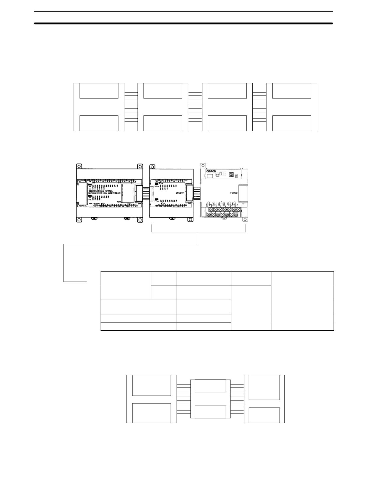
Temperature Sensor Units with 4 Inputs (4 Words Allocated): CPM1A-TS002 and CPM1A-TS102
CPM1A or CPM2A CPU Unit
CPM1A-20EDR1 CPM1A-TS002/TS102
(with 20, 30, 40, or 60 I/O points) Expansion I/O Unit Temperature Sensor Unit
Temperature
4 inputs
CPM1A-TS002 or
1 Unit only
Up to 2 Units can be
Sensor Units
CPM1A-TS102
connected. There are
no restrictions on the
2 inputs
CPM1A-TS001 or
1 Unit only
order in which Units
CPM1A-TS101
are connected
Expansion I/O Units
With 8 or 20 I/O
points
Analog I/O Units
CPM1A-MAD01
CompoBus/S I/O Link Unit
CPM1A-SRT21
Word Allocations
The CPM1A-TS002 and CPM1A-TS102 are allocated four words each (one for
each input point). No output words are allocated.
CPM1A-TS002/102
60-point CPU Unit
20-point Expansion
Temperature Sensor Unit
I/O Unit
IR 000
IR 004
IR 001
IR 003
IR 005
Input word addresses
IR 002
IR 006
IR 007
IR 010
Output word addresses
IR 011
IR 013
None
IR 012
CPM2C Temperature Sensor Unit Allocations
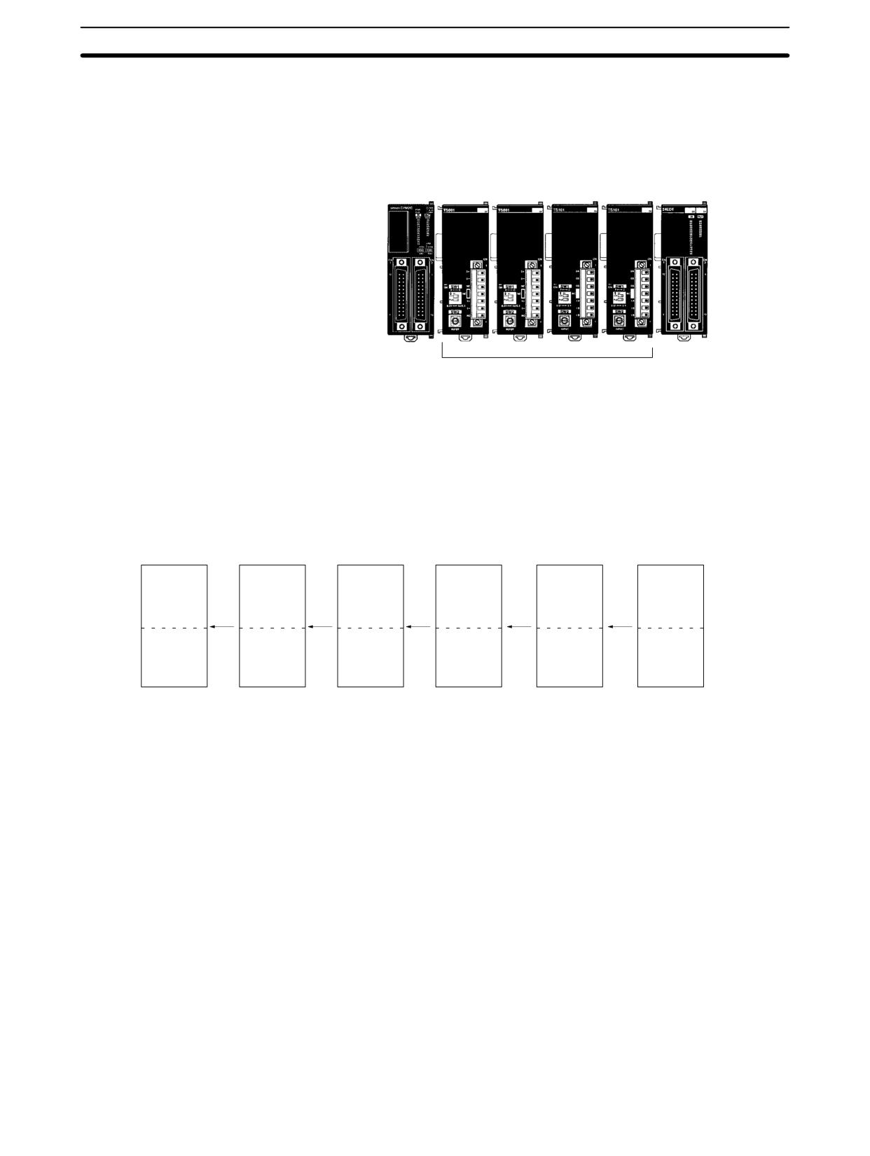
Up to four CPM2C-TS001/101 Temperature Sensor Units can be connected. Up
to a total of five Expansion I/O Units and Expansion Units can be connected (in-
192
Temperature Sensor Units
Section
3-2
cluding the Temperature Sensor Units.) Up to three Units can be connected to
the CPM2C-S. No matter how many Units are connected, however, no more
than 0 input words and 10 output words can be allocated in one PC. There are no
restrictions on the order in which Units can be connected.
Example
CPM2C-TS001/101
CPM2C CPU Unit
Temperature Sensor Units
Expansion I/O Unit
Four Temperature
Sensor Units max.
Word Allocation
Words are allocated to Temperature Sensor Units just like other Expansion I/O
Units and Expansion Units: In the order in which the Units are connected. A
CPM2C-TS001 or CPM2C-TS101 Temperature Sensor Unit will thus be allo-
cated the next two input words after the Unit to which it is connected (CPU Unit or
other Unit). No output words are allocated.
CPM2C-TS001
CPM2C-TS001
CPM2C-TS101
CPM2C-TS101
Temperature
Temperature
CPM2C-24EDTC
20-point CPU Unit
Temperature
Temperature
Expansion I/O Unit
Sensor Unit
Sensor Unit
Sensor Unit
Sensor Unit
Inputs
Inputs
Inputs
Inputs
Inputs
Inputs
IR 001
IR 003
IR 005
IR 007
IR 000
IR 009
IR 002
IR 004
IR 006
IR 008
Outputs
Outputs
Outputs
Outputs
Outputs
Outputs
IR 010
None
None
None
None
IR 011
3-2-5
Setting Temperature Ranges
The temperature unit, the number of decimal places used, and the temperature
input range are set on the DIP switch and rotary switch on the Temperature Sen-
sor Unit.
Note
1. Always turn OFF the power supply before setting the temperature range.
2. Never touch the DIP switch or rotary switch during Temperature Sensor Unit
operation. Static electricity may cause operating errors.
193
Temperature Sensor Units
Section
3-2
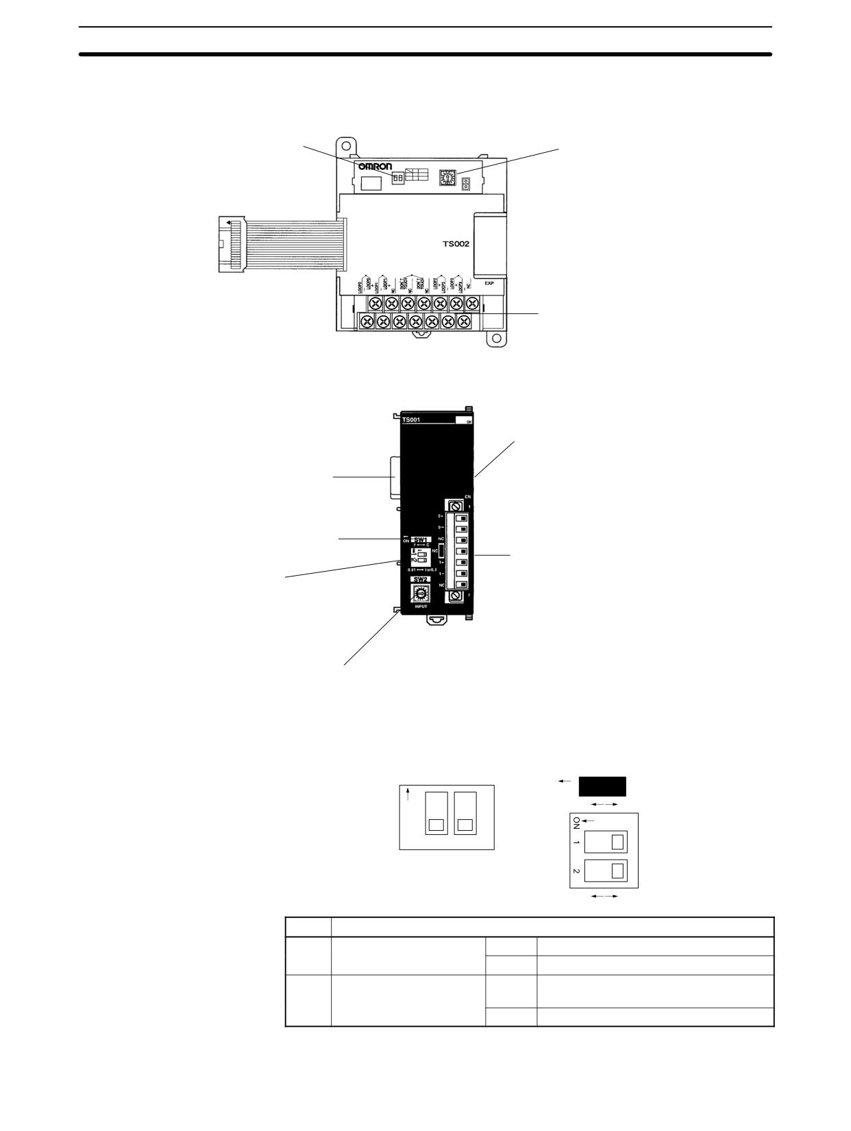
CPM1A/CPM2A Temperature Sensor Units
CPM1A-TS001/002/101/102
DIP Switch
Used to set the temperature
unit and the number of decimal
Rotary Switch
places used.
Used to set the temperature
input range.
Temperature input terminals
CPM2C Temperature Sensor Units
CPM2C-TS001/101
Expansion I/O connector (output)
Expansion I/O connector (input)
Cold junction compensator
(TS001 only)
Temperature input terminals
DIP Switch
Used to set the temperature
unit and the number of decimal
places used.
Rotary Switch
Used to set the temperature
input range.
DIP Switch Settings
The DIP switch is used to set the temperature unit (°C or °F) and the number of
decimal places used.
CPM1A-TSjjj
CPM2C-TSjjj
SW1
ON
ON
F
C
1
2
0.01
1 or 0.1
SW1
Setting
1
Temperature unit
OFF
°C
ON
°F
2
Number of decimal
OFF
Normal (0 or 1 digit after the decimal
places used
point, depending on the input range)
ON
2-decimal-place Mode (e.g., 0.01)
Note For details on 2-decimal-place Mode, refer to 3-2-8 Two-decimal-place Mode.
194
Temperature Sensor Units
Section
3-2
Note
1. Turn OFF the power supply before changing the temperature range setting.
2. Do not touch the DIP switch or rotary switches while power is turned ON.
Static electricity may cause malfunctions.
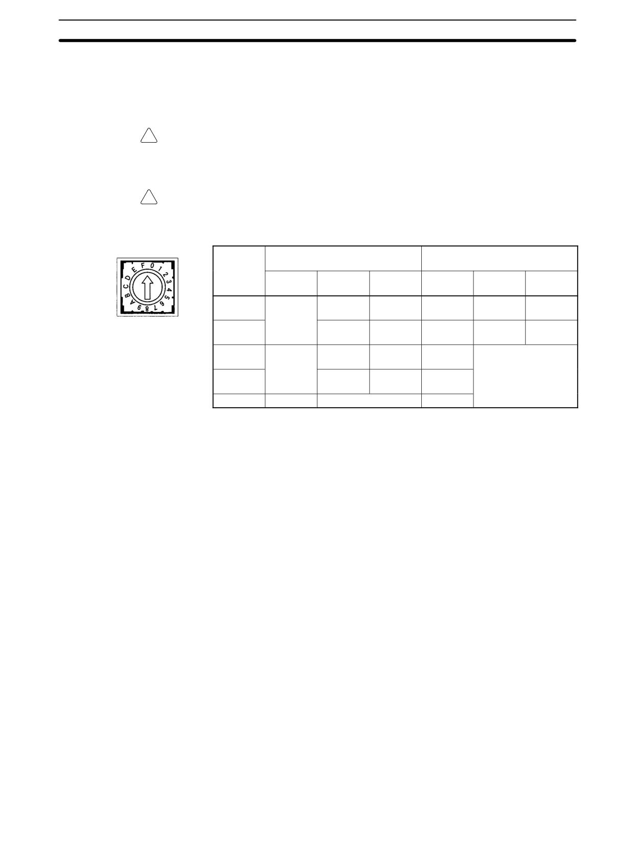
Rotary Switch Setting
The rotary switch is used to set the temperature range.
!
Caution Set the temperature range according to the type of temperature sensor con-
nected to the Unit. Temperature data will not be converted correctly if the tem-
perature range does not match the sensor.
! Caution Do not set the temperature range to any values other than those for which tem-
perature ranges are given in the following table. An incorrect setting may cause
operating errors.
Setting
CPM1A-TS001/002
CPM1A-TS101/102
CPM2C-TS001
CPM2C-TS101
Input
Range
Range
Input
Range
Range
type
(°C)
(°F)
type
(°C)
(°F)
0
K
-200 to
-300 to
Pt100
-200.0 to
-300.0 to
1,300
2,300
650.0
1,200.0
1
0.0 to
0.0 to
JPt100
-200.0 to
-300.0 to
500.0
900.0
650.0
1,200.0
2
J
-100 to
-100 to
---
Setting not possible
850
1,500
3
0.0 to
0.0 to
---
400.0
750.0
4 to F
---
Setting not possible
---
195
Temperature Sensor Units
Section
3-2
3-2-6
Connecting Temperature Sensors
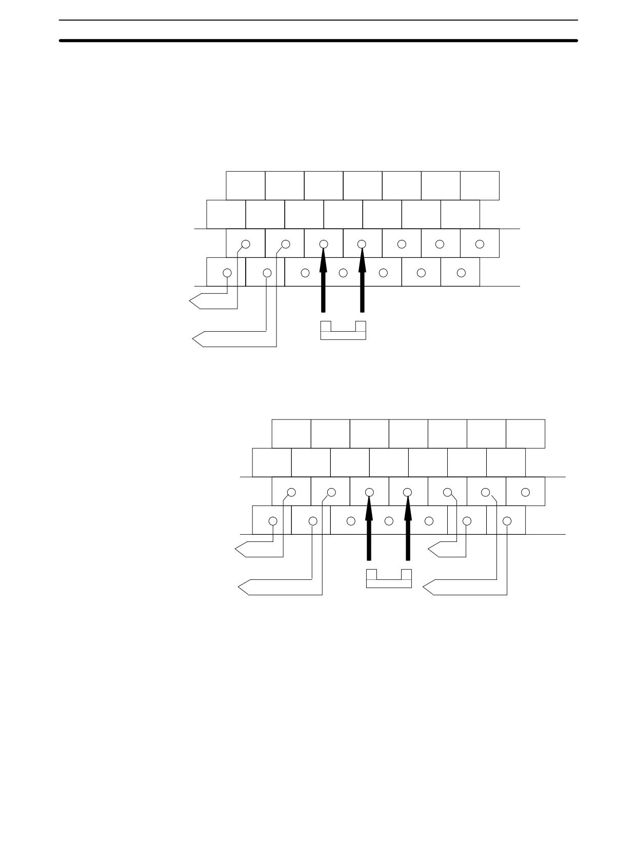
CPM1A/CPM2A Temperature Sensor Units
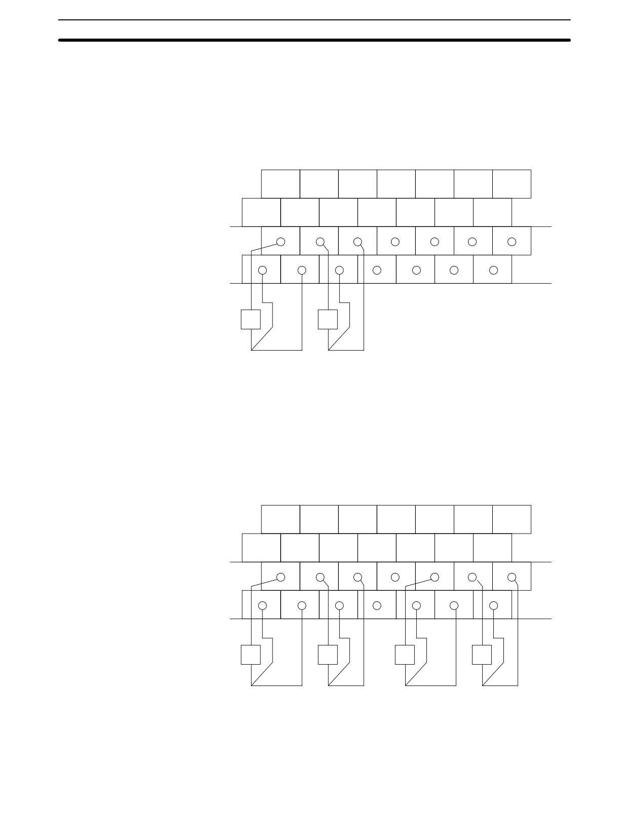
Thermocouples
CPM1A-TS001
Either K or J thermocouples can be connected, but both of the thermocouples
must be of the same type and the same input range must be used for each.
Input 0
Input 1
NC
NC
NC
+
+
Input 0
Input 1
NC
NC
NC
NC
NC
-
-
Temperature input 0
Temperature input 1
Cold junction compensator
CPM1A-TS002
Either K or J thermocouples can be connected, but all four of the thermocouples
must be of the same type and the same input range must be used for each.
Input 0
Input 1
Input 2
Input 3
NC
+
+
+
+
Input 0
Input 1
NC
NC
NC
Input 2
Input 3
–
-
-
-
Temperature
Temperature
input 0
input 2
Cold junction
Temperature
Temperature
compensator
input 1
input 3
Note When using a Temperature Sensor Unit with a thermocouple input, observe the
following precautions:
• Do not remove the cold junction compensator attached at the time of deliv-
ery. If the cold junction compensator is removed, the Unit will not be able to
measure temperatures correctly.
• Each of the input circuits is calibrated with the cold junction compensator
attached to the Unit. If the Unit is used with the cold junction compensator
from other Units, the Unit will not be able to measure temperatures cor-
rectly.
• Do not touch the cold junction compensator. Doing so may result in incor-
rect temperature measurement.
196
Temperature Sensor Units
Section
3-2
Platinum Resistance
Thermometers
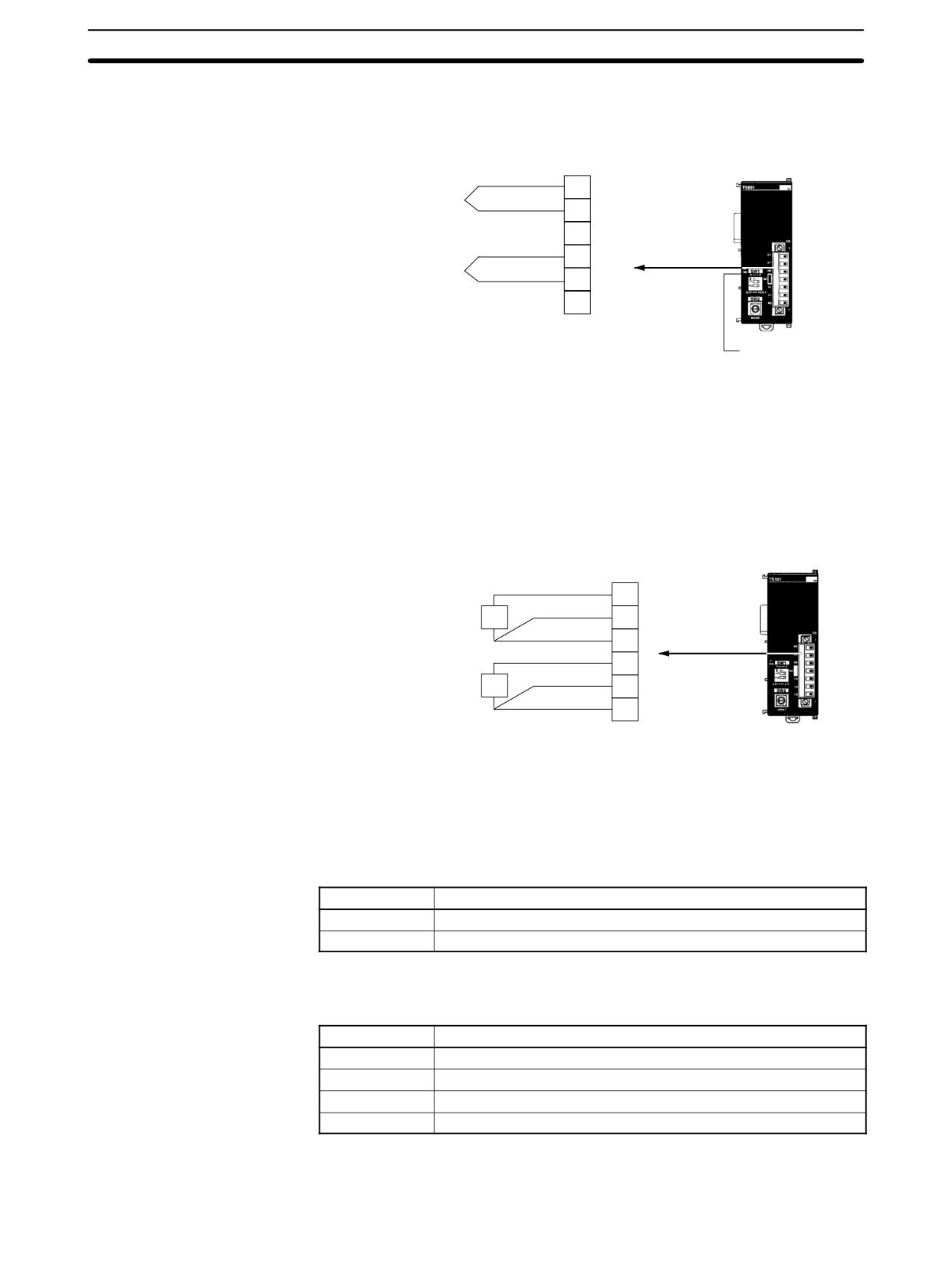
CPM1A-TS101
Either Pt100 or JPt100 platinum resistance thermometers can be connected,
but both of the thermometers must be of the same type and the same input range
must be used for each.
Input 0
Input 1
Input 1
NC
NC
NC
NC
A
A
B
Input 0
Input 0
Input 1
NC
NC
NC
NC
B
B
B
Pt
Pt
Temperature input 0
Temperature input 1
CPM1A-TS102
Either Pt100 or JPt100 platinum resistance thermometers can be connected,
but all four of the thermometers must be of the same type and the same input
range must be used for each.
Input 0
Input 1
Input 1
NC
Input 2
Input 3
Input 3
A
A
B
A
A
B
Input 0
Input 0
Input 1
NC
Input 2
Input 2
Input 3
B
B
B
B
B
B
Pt
Pt
Pt
Pt
Temperature
Temperature
Temperature
Temperature
input 0
input 1
input 2
input 3
Note Do not connect anything to terminals not used for inputs.
197
Temperature Sensor Units
Section
3-2
CPM2C Temperature Sensor Units
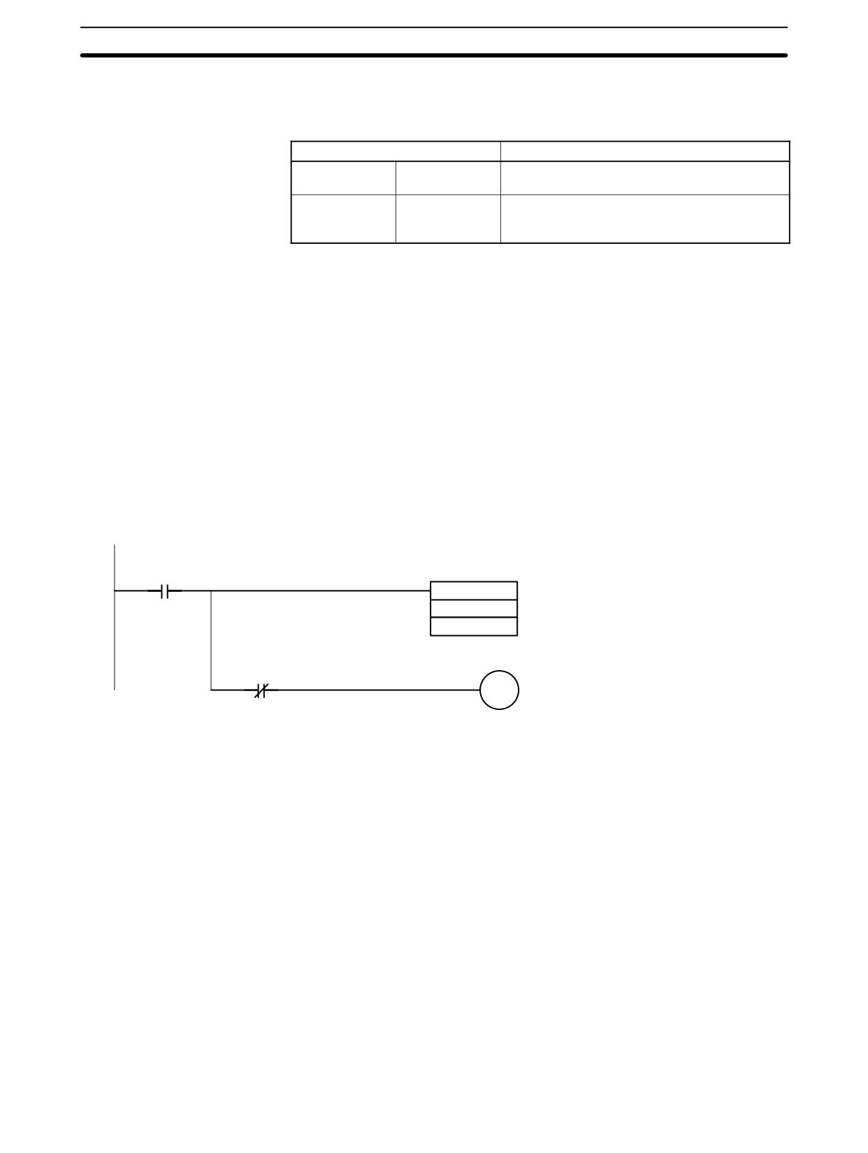
CPM2C-TS001 (Thermocouples)
Either K or J thermocouples can be connected, but both of the thermocouples
must be of the same type and the same input range must be used for each.
0+
Temperature input 0
0-
NC
1+
1-
Temperature input 1
NC
Cold junction
compensator
Note When using a Temperature Sensor Unit with a thermocouple input, observe the
following precautions:
• Do not touch the cold junction compensator. Doing so may result in incor-
rect temperature measurement.
CPM2C-TS101 (Platinum Resistance Thermometers)
Either Pt100 or JPt100 platinum resistance thermometers can be connected,
but both of the thermometers must be of the same type and the same input range
must be used for each.
0A
Pt
0B
Temperature input 0
0B
1A
Pt
1B
Temperature input 1
NC
3-2-7
Ladder Programming
Converted Temperature
The temperature data will be stored in the input words allocated to the Tempera-
Data
ture Sensor Unit in 4-digit hexadecimal.
CPM1A-TS001/TS101 and CPM2C-TS001/TS101
“m” is the last word allocated to the CPU Unit, Expansion I/O Unit, or Expansion
Unit connected immediately before the Temperature Sensor Unit.
Word
Contents
m + 1
Converted temperature data from input 0
m + 2
Converted temperature data from input 1
CPM1A-TS002/TS102
“m” is the last word allocated to the CPU Unit, Expansion I/O Unit, or Expansion
Unit connected immediately before the Temperature Sensor Unit.
Word
Contents
m + 1
Converted temperature data from input 0
m + 2
Converted temperature data from input 1
m + 3
Converted temperature data from input 2
m + 4
Converted temperature data from input 3
All Temperature Sensor Units
Negative values are stored as 2’s complements. Data for range codes that in-
198
Temperature Sensor Units
Section
3-2
clude one digit after the decimal point are stored without the decimal point, i.e.,
10 times the actual value is stored. Some examples are provided in the following
table.
Input
Data conversion examples
Unit: 1°
K or J
850° → 0352 Hex
-200° → FF38 Hex
Unit: 0.1°
K, J, Pt100 or
×10
500.0° → 5000 → 1388 Hex
JPt100
-20.0° → -200 → FF38 Hex
-200.0° → -2000 → F830 Hex
If the input temperature exceeds the range that can be converted, the converted
temperature data will be held at the maximum or minimum value in the range. If
the input temperature exceeds the range by more than a specified amount, the
open-circuit detection function will detect an open-circuit and the converted tem-
perature data will be set to 7FFF. The open-circuit detection function will also
operate if the cold junction compensator is faulty. The open-circuit detection
function will be automatically cleared and normal input temperature conversion
will begin automatically when the input temperature returns to the convertible
range.
After power is turned ON, it will require approximately 1 s before the first data is
Startup Operation
converted. The following instructions can be placed at the beginning of the pro-
gram and then IR 02000 can be used to delay reading converted data until con-
version is actually begun.
25313
(Always ON Flag)
CMP (20)
User flag indicating that temperature data
001
conversion has begun.
#7FFE
25506 (=)
02000
User-defined flag indicating that initializa-
tion has been completed
Note Input data will be 7FFE until actual conversion starts.
If an error occurs in an Expansion Unit, the Error Flags in AR 0200 to AR 0204
Handling Unit Errors
will be turned ON ( AR 0200 to AR 0202 for the CPM1A/CPM2A). Refer to page
568 for details. The addresses of the Error Flags are in order that the Expansion
Units are connected in the PC, with AR 0200 used for the Expansion Unit closest
to the CPU Unit. Use these flags in the program when it is necessary to detect
errors.
When an error occurs in a Temperature Sensor Unit, converted temperature
data will be 7FFF.
Note The status of AR 0200 to AR 0204 will not change for the open-circuit detection
function.
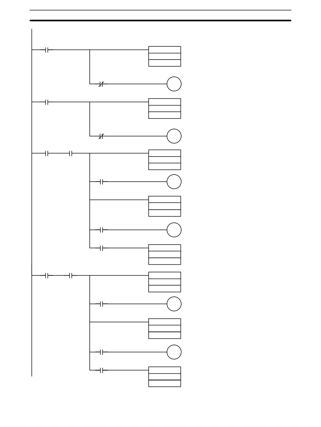
The following programming example shows how to convert the input data from 2
Programming Example 1
temperature sensor inputs to BCD and store the result in DM 0000 and
DM 0001. The following system configuration is used.
199

Temperature Sensor Units
Section
3-2
20-point CPU Unit
Temperature Sensor Unit
Inputs
Inputs
IR 000
IR 001
IR 002
Temperature unit setting:
OFF (°C)
Two-decimal-place Mode:
OFF (normal)
Input range setting:
1 (K2, 0.0 to 500.0°C)
Temperature input 0 storage word:
IR 001
Outputs
Outputs
Temperature input 1 storage word:
IR 002
IR 010
None
200
Temperature Sensor Units
Section
3-2
25313
(Always ON Flag)
CMP (20)
Detects completion of input 0 initialization.
001
#7FFE
25506(=)
ON when input 0 has been initialized
02000
25313
(Always ON Flag)
CMP (20)
Detects completion of input 1 initialization.
002
#7FFE
25506
02001
ON when input 1 has been initialized
02000
Execution condition
CMP (20)
Detects an open-circuit alarm or Unit error by check-
ing converted temperature data for the error code
001
7FFF.
#7FFF
25506(=)
01000
ON when an open-circuit alarm or Unit error has been
detected for input 0.
CMP (20)
Checks to see if the temperature data in IR 001 has
001
exceeded 500.0°C (1388 Hex without decimal point).
#1388
25505(>)
01001
ON for an input 0 temperature error
25507(<)
BCD (24)
Converts the contents of IR 001 (temperature data
for input 0) to BCD and stores the result in
001
DM 0000.
DM0000
02001
Execution condition
CMP (20)
Detects an open-circuit alarm or Unit error by check-
ing converted temperature data for the error code
002
7FFF.
#7FFF
25506(=)
ON when an open-circuit alarm or Unit error has been
01002
detected for input 1.
CMP (20)
Checks to see if the temperature data in IR 002 has
002
exceeded 500.0°C (1388 Hex without decimal point).
#1388
25505(>)
01003
ON for an input 1 temperature error
25507(<)
BCD (24)
Converts the contents of IR 002 (temperature data
for input 1) to BCD and stores the result in
002
DM 0001.
DM0001
201
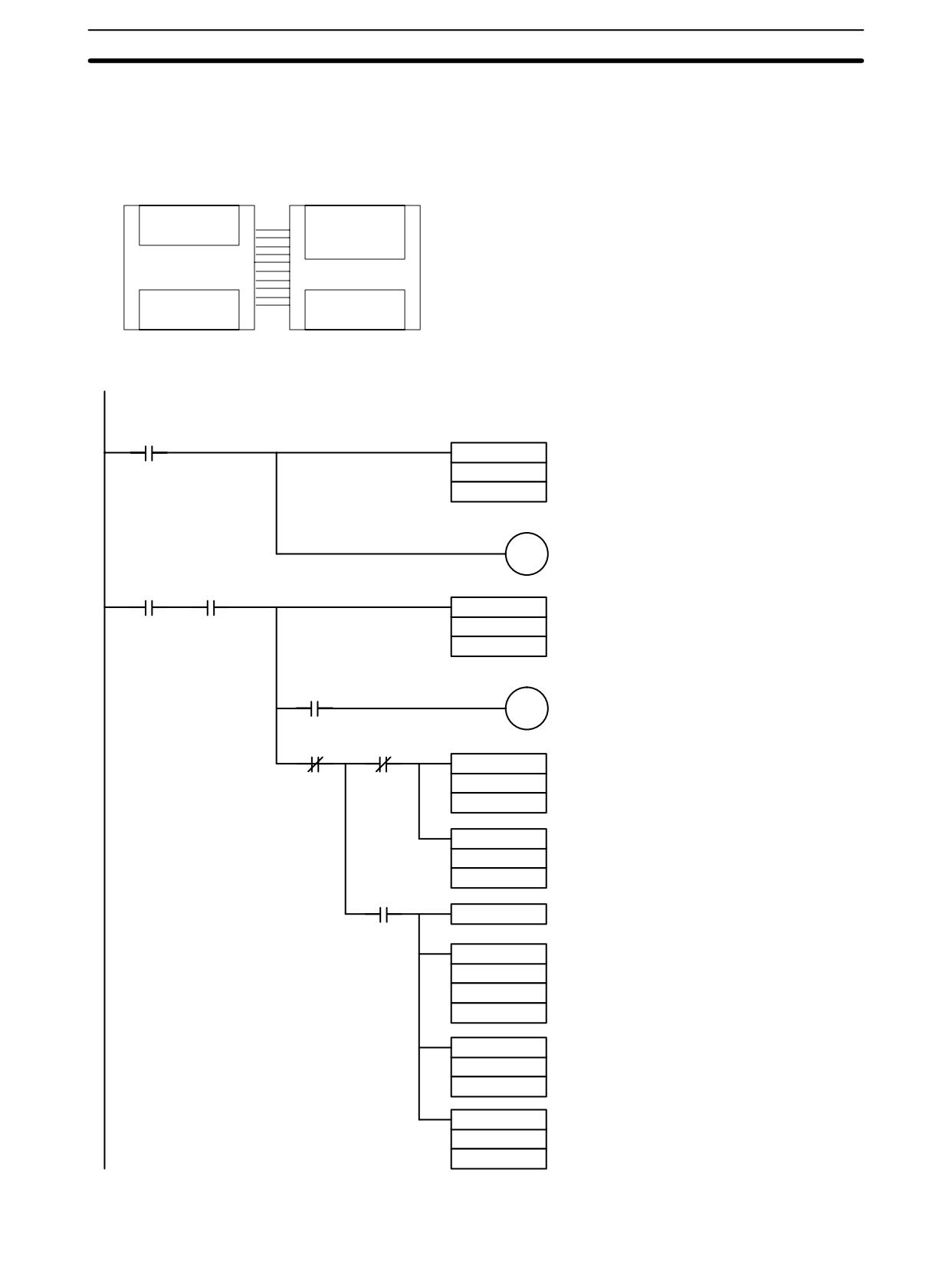
Temperature Sensor Units
Section
3-2
The following programming example shows how to convert the data for temper-
Programming Example 2
ature input 0 to BCD and store the result in DM 0000 and DM 0001. “0001” is
stored in DM 0001 when the input data is a negative value. The following system
configuration is used.
20-point CPU Unit
Temperature Sensor Unit
Inputs
Inputs
IR 000
IR 001
IR 002
Temperature unit setting:
OFF (°C)
Two-decimal-place Mode:
OFF (normal)
Input range setting:
1 (Pt100, -200.0 to 650.0°C)
Temperature input 0 storage word:
IR 001
Outputs
Outputs
IR 010
None
Programming with BCD(24) Instruction
25313
(Always ON Flag)
CMP (20)
Detects completion of input 0 initialization.
001
#7FFE
ON when input 0 has been initialized
02000
02000
Execution condition
CMP (20)
Detects an open-circuit alarm or Unit error by check-
ing converted temperature data for the error code
002
7FFF.
#7FFF
25506(=)
ON when an open-circuit alarm or Unit error has been
01000
detected for input 0.
25506(=)
00115
BDC (24)
When the input temperature data is non-negative,
001
converts the contents of IR 001 (temperature data
for input 0) to BCD and stores the result in
DM0000
DM 0000.
MOV (21)
Stores #0000 in DM 0001.
#0000
DM0001
00115
CLC (41)
SBB (51)
When the input temperature data is negative, con-
#0000
verts the contents of IR 001 to the absolute value of
001
the actual temperature and stores the result in
DM 0010.
DM0010
Converts the contents of DM 0010 (absolute value
BCD (24)
of negative temperature data for input 0) to BCD
DM0010
and stores the result in DM 0000.
DM0010
MOV (21)
Stores #0001 in DM 0001 to indicate a negative
number.
#0001
DM0001
202
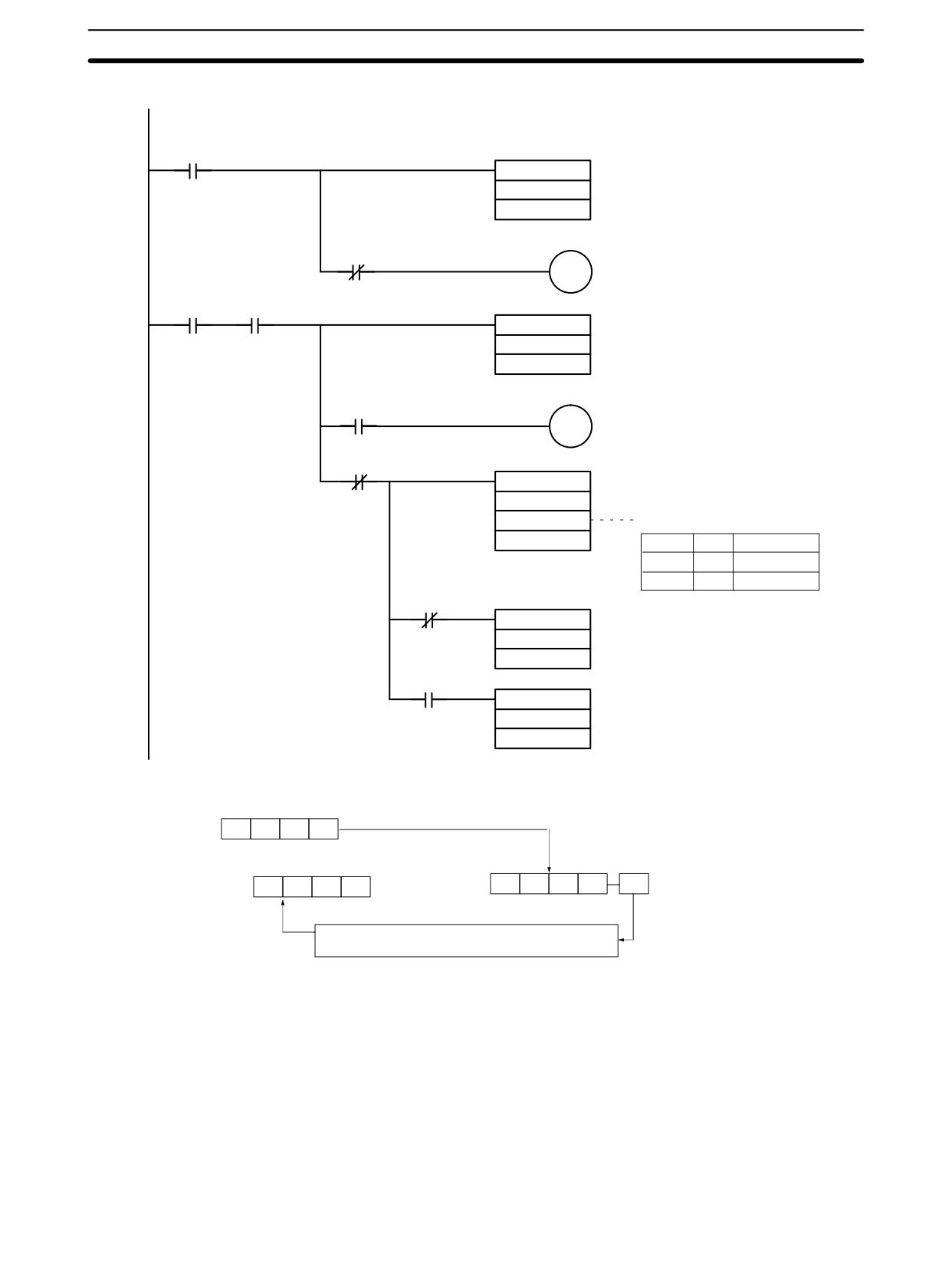
Temperature Sensor Units
Section
3-2
Programming with SCL2(--) Instruction (CPM2A/CPM2C Only)
25313
(Always ON Flag)
CMP (20)
Detects completion of initialization.
001
#7FFE
25506(=)
02000
ON when initialization complete.
02000
Execution condition
CMP (20)
Detects an open-circuit alarm.
001
#7FFF
25506(=)
01000
ON when an open-circuit alarm has been detected.
25506(=)
SCL2 (-)
001
DM0010
Parameter settings for data conversion:
DM0000
DM0010
#0000
Offset
DM0011
#0001
∆X (Hex)
DM0012
#0001
∆Y (BCD)
25504(CY)
When the converted value is non-negative,
MOV (21)
stores #0000 in DM 0001.
#0000
DM0001
25504(CY)
When the converted value is negative, stores
MOV (21)
#0001 in DM 0001.
#0001
DM0001
Operation
Binary to BCD conversion
IR 001
163
162
161
160
DM 0000
CY (when using SCL2 instruction)
DM 0001
0
0
0
1/0
103
102
101
100
1/0
1: Negative, 0: Non-negative
0: If data non-negative, “0000” stored in DM 0001
1: If data negative, “0001” stored in DM 0001
203
Temperature Sensor Units
Section
3-2
3-2-8
Two-decimal-place Mode
If pin 2 on the DIP switch is turned ON, values are stored to two decimal places.
In this case, temperature data is stored as 6-digit signed hexadecimal (binary)
data with 4 digits in the integer portion and 2 digits after the decimal point. The
actual data stored in memory is 100 times the actual value, i.e., the decimal point
is not indicated. Methods for handling this data are described in this section.
Note When set to store values to two decimal places, temperature data as far as two
digits after the decimal point is converted to 6-digit binary data, but the actual
resolution is not 0.01°C (°F). For this reason, there may be skipping and inaccu-
racies in the first digit after the decimal point (0.1). Treat any resolution above
that specified for the normal data format as reference data.
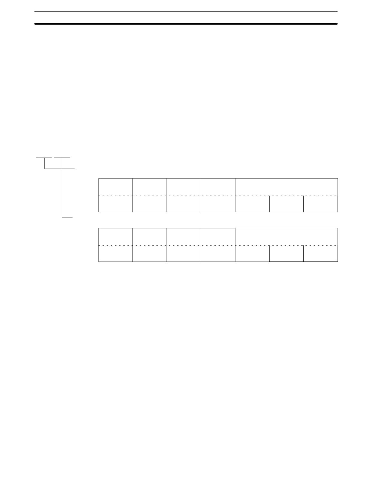
Data Structure
The structure of the data stored in memory is shown below. The value will be 100
times the actual temperature.
jjjjjj
Leftmost 3 Digits and Flags
15
14
13
12
Leftmost/
Temperature
Open-circuit
Not used.
Temperature data
Rightmost Flag
Unit Flag
Flag
0: Leftmost
0: °C
0: Normal
Always 0
x165
x164
x163
1: Rightmost
1: °F
1: Error
Rightmost 3 Digits and Flags
15
14
13
12
Leftmost/
Temperature
Open-circuit
Not used.
Temperature data
Rightmost Flag
Unit Flag
Flag
0: Leftmost
0: °C
0: Normal
Always 0
1: Rightmost
1: °F
1: Error
x162
x161
x160
Leftmost/Rightmost Flag: Indicates whether the leftmost or rightmost 3 digits are provided.
Temperature Unit Flag:
Indicates whether the temperature is in °C or °F.
Open-circuit Flag:
Turns ON (1) when an open-circuit is detected. The temperature
data will be 7FF FFF if this flag is ON.
204
Temperature Sensor Units
Section
3-2
Data Conversion
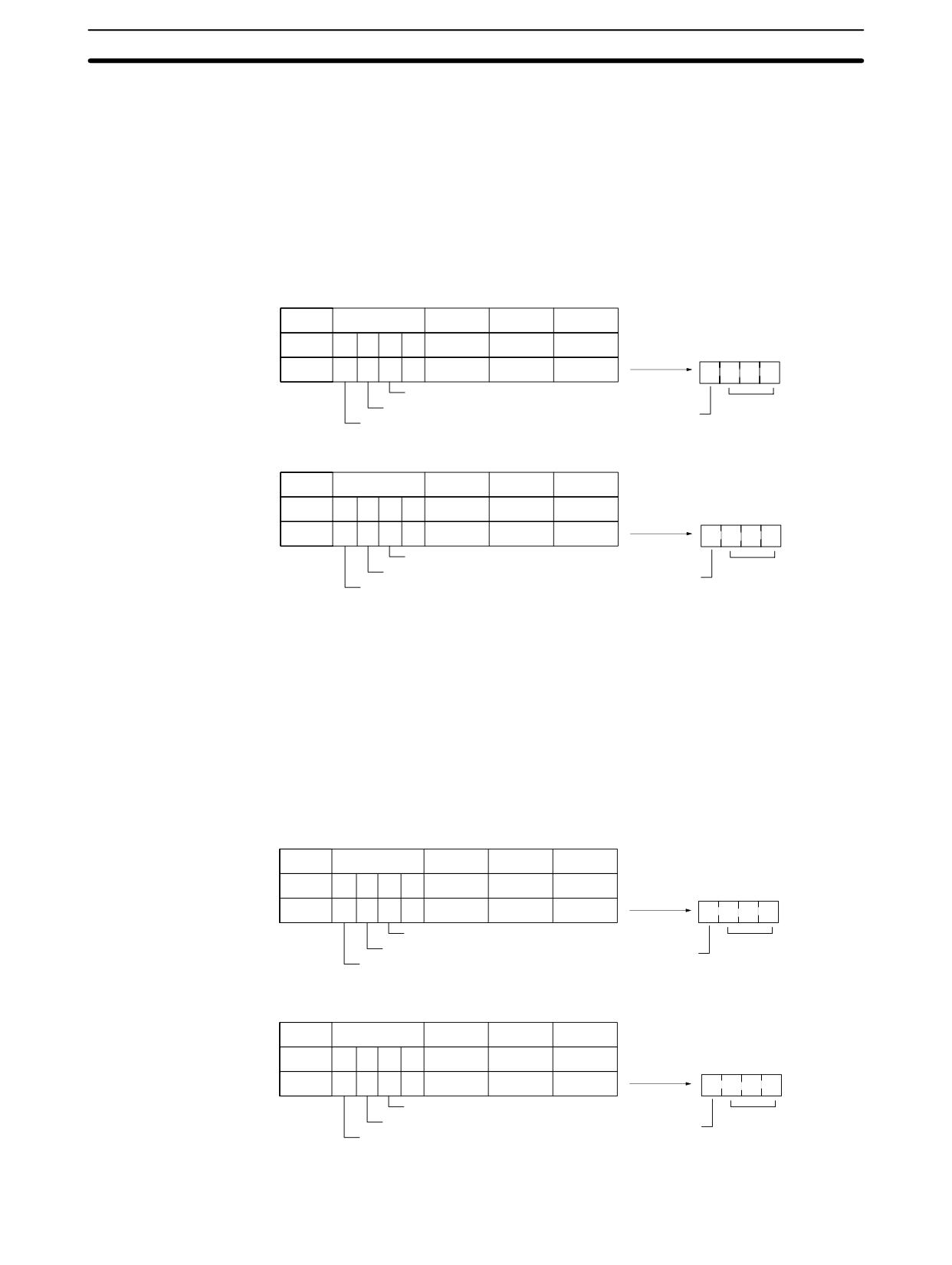
Some examples of the data stored for various temperature inputs are provided
Examples
below.
Example 1
Temperature:
1,130.25°C
×100:
113025
Temperature Data: 01B981 (hexadecimal for 113025)
Leftmost 3 Digits and Flags
Flags
x165
x164
x163
Bits
15
14
13
12
08 to 11
04 to 07
00 to 03
Data
0
0
0
0
0
1
B
0
0
1
B
Normal
Temperature
°C
Flags
data
Leftmost
Rightmost 3 Digits and Flags
Flags
x162
x161
x160
Bits
15
14
13
12
08 to 11
04 to 07
00 to 03
Data
1
0
0
0
9
8
1
8
9
8
1
Normal
Temperature
°C
Flags
data
Rightmost
Example 2
Temperature:
-100.12°C
×100:
-10012
Temperature Data: FFD8E4 (hexadecimal for -10012)
Leftmost 3 Digits and Flags
Flags
x165
x164
x163
Bits
15
14
13
12
08 to 11
04 to 07
00 to 03
Data
0
0
0
0
F
F
D
0
F
F
D
Normal
°C
Flags
Temperature
Leftmost
data
Rightmost 3 Digits and Flags
Flags
x162
x161
x160
Bits
15
14
13
12
08 to 11
04 to 07
00 to 03
Data
1
0
0
0
8
E
4
8
8
E
4
Normal
°C
Flags
Temperature
Rightmost
data
205
Temperature Sensor Units
Section
3-2
Example 3
Temperature:
-200.12°F
×100:
-20012
Temperature Data: FFB1D4 (hexadecimal for -20012)
Leftmost 3 Digits and Flags
Flags
x165
x164
x163
Bits
15
14
13
12
08 to 11
04 to 07
00 to 03
Data
0
0
0
0
F
F
B
4
F
F
B
Normal
°F
Temperature
Flags
Leftmost
data
Rightmost 3 Digits and Flags
Flags
x162
x161
x160
Bits
15
14
13
12
08 to 11
04 to 07
00 to 03
Data
1
0
0
0
1
D
4
C
1
D
4
Normal
°F
Flags
Temperature
Rightmost
data
Example 4
Temperature:
Open circuit (°F)
Temperature Data: 7FFFFFFF
Leftmost 3 Digits and Flags
Flags
x165
x164
x163
Bits
15
14
13
12
08 to 11
04 to 07
00 to 03
Data
0
1
1
0
7
F
F
6
7
F
F
Error
Temperature
°F
Flags
data
Leftmost
Rightmost 3 Digits and Flags
Flags
x162
x161
x160
Bits
15
14
13
12
08 to 11
04 to 07
00 to 03
E
F
F
F
Data
1
1
1
0
F
F
F
Error
Temperature
°F
Flags
data
Rightmost
Note
1. Leftmost digits are stored in the lower memory addresses. Treat the data in
the lower memory address as the leftmost digits when programming.
2. Be sure that the data is read at least once every 125 ms to allow for the CPU
Unit’s cycle time and communications time. Correct data may not be ob-
tained if the read cycle is greater than 125 ms.
206
Temperature Sensor Units
Section
3-2
Programming Example
The following programming example shows how to use 2-decimal-place Mode
for the following PC configuration.
20-point CPU Unit
20-point Expansion
Temperature Sensor Unit
I/O Unit
Temperature unit setting:
Inputs
Inputs
Inputs
OFF (°C)
IR 000
IR 001
IR 002
IR 003
Two-decimal-place Mode:
ON (2 digits after decimal point stored)
Outputs
Outputs
Outputs
IR 010
IR 011
None
In this example, 100 times the temperature data for temperature input 0 is stored
in binary form in DM 0100 to DM 0102.
Leftmost data
IR 200
Temperature input 0
IR 002
Rightmost data
Bit
15
14
13
12
11
10
9
8
7
6
5
4
3
2
1
0
DM 0100
x163
x162
x161
x160
DM 0101
x167
x166
x165
x164
DM 0102
Always 0
Always 0
Always 0
0
0
Temperature Unit Flag (0: °C, 1: °F)
Open-circuit Flag (0: Normal, 1: Error)
The following program would be used.
207
Temperature Sensor Units
Section
3-2
25315
(First Scan Flag)
MOV (21)
(1)
Sets DM 0103 and DM 0102 to
#0000
#0100 and #0000, respectively.
DM0102
MOV (21)
#0100
25313
DM0103
(Always ON Flag)
CMP (20)
002
Detects completion of input 0 initialization.
#7FFE
25506(=)
02000
ON when input 0 has been initialized.
02000
00213 (open-circuit detected)
01000
Open-circuit alarm output
00215 (leftmost digits)
SET 02001
Ready for data conversion.
02001
00215 (leftmost digits)
MOV (21)
(2)
Leftmost digits moved to IR 200
002
200
00215 (rightmost digits)
(3)
MOVD (83)
002
Leftmost and rightmost digits
#0020
rearranged and moved to
IR 202 and IR 201.
201
MOVD (83)
(4)
200
#0300
201
MOVD (83)
(5)
200
#0011
202
RSET 02001
RSET 02002
Data rearrangement completed.
(continued next page.)
208
Temperature Sensor Units
Section
3-2
02002
00207 (non-negative data)
BCDL (59)
(6)
201
If the temperature data is non-negative, the
binary data in IR 202 and IR 201 is converted
DM0100
to BCD and placed in DM 0101 and DM 0100.
00207 (negative data)
CLC (41)
(7)
If the temperature data is negative, the 2’s
SBB (51)
complement data in IR 202 and IR 201 is
DM0102
converted to binary data representing the
201
absolute value of the temperature input
and placed in HR 01 and HR 00.
HR00
SBB (51)
DM0103
202
HR01
BCDL (59)
(8)
The binary data in HR 01 and HR 00 is con-
HR00
verted to BCD and placed in DM 0101 and
DM0100
DM 0100.
MOVD (83)
(9)
“1” is written to the bit in DM 0101
#0008
indicating negative data.
#0300
DM0101
RSET 02002
Note The BCDL(59) instruction is only available with the CPM2A and CPM2C.
The data movements corresponding to the numbers in the above ladder pro-
gramming example are illustrated in the following diagram.
IR 002: Leftmost 3 digits of temperature data
IR 002: Rightmost 3 digits of temperature data
0
165
164
163
1
162
161
160
(2)
(3)
IR 200
0
165
164
163
(4)
(5)
IR 202
0
0
165
164
IR 201
164
163
161
160
(6)
If the temperature data is non-negative, the
binary data in IR 202 and IR 201 is converted
to BCD and placed in DM 0101 and DM 0100.
DM0101
0/8
106
105
104
DM0100
103
102
101
100
(9)
(8)
If temperature data is negative, “8” is written here
If the temperature data is negative, the binary
(i.e., “1” is written to the bit indicating negative data).
data in HR 01 and HR 00 is converted to BCD
and placed in DM 0101 and DM 0100.
(1)
#0100
(1)
#0000
DM0103
0
1
0
0
DM0102
0
0
0
0
–
IR 202
2’s complement data
IR 201
2’s complement data
HR 01
0
0
165
164
HR 00
163
162
161
160
(7)
The 2’s complement data in IR 202 and IR 201 is subtracted, as binary data,
from the data in DM 0103 and DM 0102 and placed in HR 01 and HR 00.
209
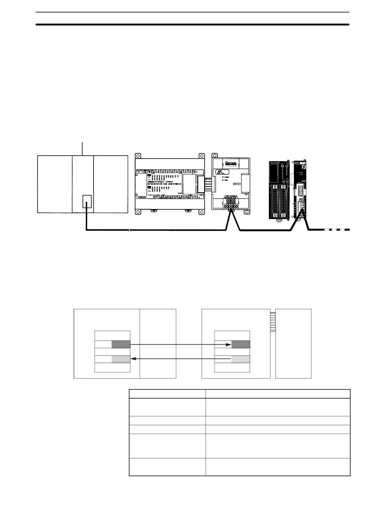
CompoBus/S I/O Link Units
Section
3-3
3-3
CompoBus/S I/O Link Units
The CPM1A, CPM2A, or CPM2C (including the CPM2C-S) PCs can function as
Slaves to a CompoBus/S Master Unit (or SRM1 CompoBus/S Master Control
Unit) when a CompoBus/S I/O Link Unit is connected. The CompoBus/S I/O Link
Unit establishes an I/O link of 8 inputs and 8 outputs between the Master Unit
and the PC.
Note For the CPM1A, a CPM1A CPU Unit with 30 or 40 I/O points must be used to
connected the CompoBus/S I/O Link Unit. It cannot be connected to a CPM1A
CPU Unit with 10 or 20 I/O points.
CompoBus/S Master Unit
(or SRM1 CompoBus/S
CPM1A-SRT21
Master Control Unit)
CompoBus/S
CPM1A/CPM2A CPU Unit
I/O Link Unit
CPM2C
CPM2C-SRT21
or CPM2C-S
CompoBus/S
CPU Unit
I/O Link Unit
Special flat cable or VCTF cable
From the standpoint of the CPU Unit, the 8 input bits and 8 output bits allocated
to the CompoBus/S I/O Link Unit are identical to input and output bits allocated to
Expansion I/O Units even though the CompoBus/S I/O Link Unit does not control
actual inputs and outputs. The input and output bits allocated to the Compo-
Bus/S I/O Link Unit are one side of an I/O link between the slave CPU Unit and
the CPU Unit to which the Master Unit is connected.
Master PC (CS1 Series)
CPM1A, CPM2A, or CPM2C
CPU Unit
CompoBus/S
CPU Unit with 30 I/O points
CompoBus/S
Master Unit
I/O Link Unit
I/O memory
I/O memory
Unit No. 0
Node
8 bits
8 bits
number:
Output
Input
0
2000
IR 002
8 bits
8 bits
Input
Output
2004
IR 012
Specifications
Item
Specification
Model number
CPM1A or CPM2A:
CPM1A-SRT21
CPM2C or CPM2C-S :
CPM2C-SRT21
Master/slave
CompoBus/S Slave
Number of I/O points
8 input points, 8 output points
Number of words allocated
1 input word, 1 output word
in CPU Unit I/O memory
(Allocated in the same way as Expansion I/O Units
and other Expansion Units)
Node number setting
Set using the DIP switch
(Set before turning on the CPU Unit’s power supply.)
210
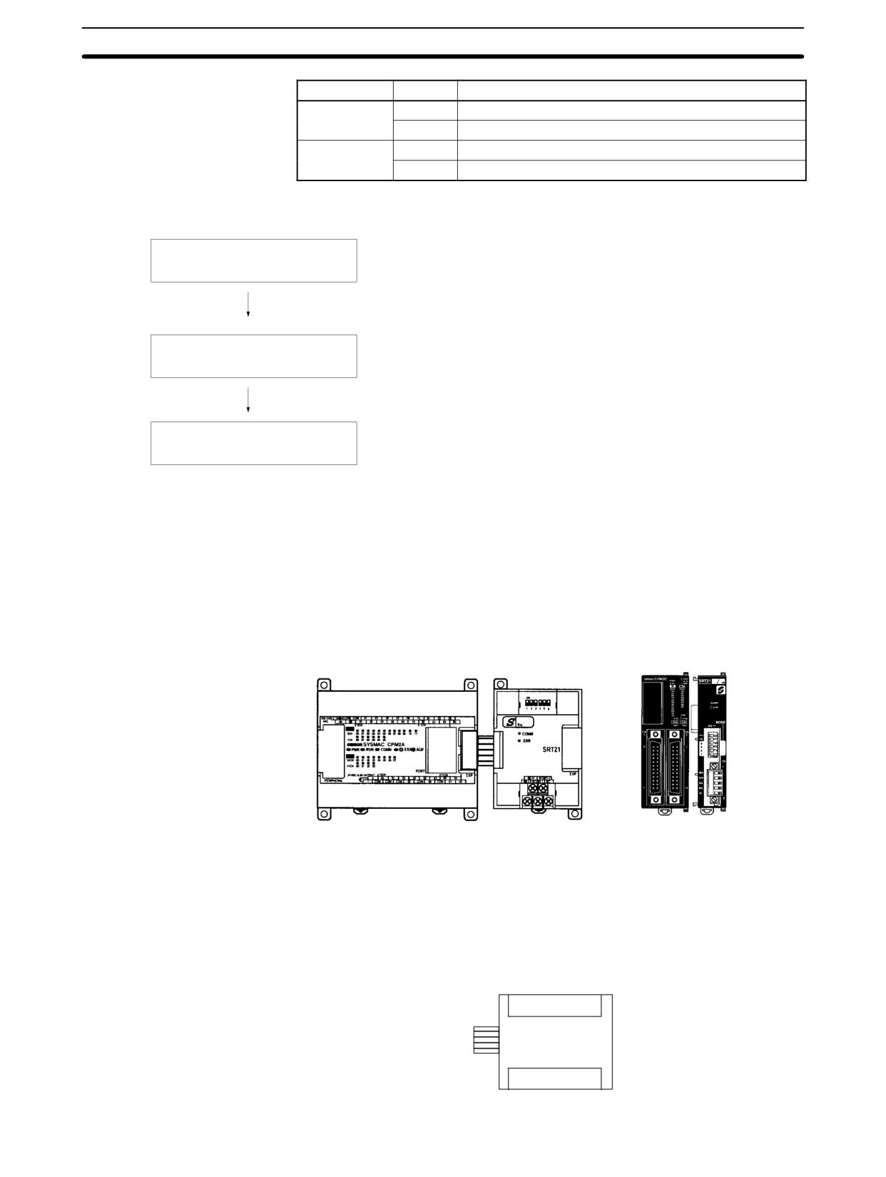
CompoBus/S I/O Link Units
Section
3-3
LED Indicators
Indicator
Status
Meaning
COMM
ON
Communications in progress.
(yellow
)
OFF
Communications stopped or error has occurred.
ERR
ON
A communications error has occurred.
(red)
OFF
Indicates normal communications or stand-by.
Usage Procedure
Connect the Unit.
Connect the CompoBus/S I/O Link Unit.
The node number should be a unique number between 0 and 15.
Determine the node address of
the CompoBus/S I/O Link Unit and
Use the DIP switch to set the CompoBus/S I/O Link Unit’s node
set the DIP switch.
number, communications mode, and the status of output data
when a communications error occurs.
Wire the CompoBus/S transmission
Connect the CompoBus/S I/O Link Unit to a CompoBus/S
path.
transmission path.
Connecting the
Connect the CompoBus/S I/O Link Unit to the CPU Unit. The number of Compo-
CompoBus/S I/O Link
Bus/S I/O Link Units that can be connected depends on the PC. Three Units can
Unit
be connected to the CPM1A/CPM2A, five Units can be connected to the
CPM2C, and three Units can be connected to the CPM2C-S. When Expansion
I/O Units or other Expansion Units are also connected, they can be connected in
any order from the CPU Unit.
CPM1A-SRT21
CPM2C or
CompoBus/S
CPM2C-S CompoBus/S I/O
CPM1A/CPM2A CPU Unit
I/O Link Unit
CPU Unit
Link Unit
I/O Allocation
I/O words are allocated to the CompoBus/S I/O Link Unit in the same way as
Expansion I/O Units or other Expansion Units, the next available input and out-
put words are allocated. When “m” is the last allocated input word and “n” is the
last allocated output word, the CompoBus/S I/O Link Unit is allocated “m+1” as
its input word and “n+1” as its output word.
CompoBus/S I/O Link Unit
Word m+1
bits 00 to 07
8 inputs
8 outputs
Word n+1
bits 00 to 07
211
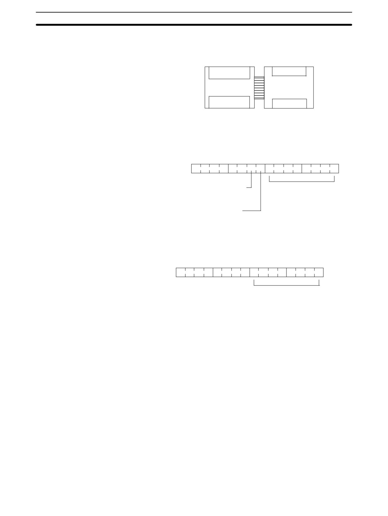
CompoBus/S I/O Link Units
Section
3-3
In the following example, a CompoBus/S I/O Link Unit is connected to a CPU
Unit with 30 I/O points.
IR 000
IR 002
Input words
IR 001
CPU Unit with
CompoBus/S
30 I/O points
I/O LInk Unit
IR 010
Output words
IR 011
IR 012
The input word (m+1) contains the 8 bits of data from the Master Unit and two
CompoBus/S communications flags.
15
09 08 07
00
Word m+1
0
0
0
0
0
0
Data from the Master Unit
CompoBus/S Communications Error Flag
0: Normal; 1: Error
CompoBus/S Communication Status Flag
0: Stopped; 1: Communicating
Write the data to be transmitted to the Master Unit in the output word (n+1).
15
07
00
Word n+1
0
0
0
0
0
0
0
0
Data to be transferred to the Master Unit
The 8 bits of I/O data are not always transmitted simultaneously. In other words,
8 bits of data transmitted from the Master CPU Unit at the same time will not al-
ways reach the Slave CPU Unit simultaneously, and 8 bits of data transmitted
from the Slave CPU Unit at the same time will not always reach the Master CPU
Unit simultaneously.
When the 8 bits of input data must be read together, modify the ladder program in
the CPU Unit receiving the data. For example, read the input data twice in suc-
cession and accept the data only when the two values match.
Unused bits in the CompoBus/S I/O Link Unit’s output word can be used as work
bits, but unused bits in the output slaves cannot be used as work bits.
Unused bits in input word cannot be used as work bits.
Determining the Node Number and Making DIP Switch Settings
Node Number
The CompoBus/S I/O Link Unit is a Slave Unit with 8 input bits and 8 output bits.
The node number setting is made using the DIP switch; the inputs and outputs
share the same node number.
The range of possible node number settings is determined by the type of PC the
Master Unit is mounted to and the settings on the Master Unit. For details refer to
the CompoBus/S Operation Manual.
212
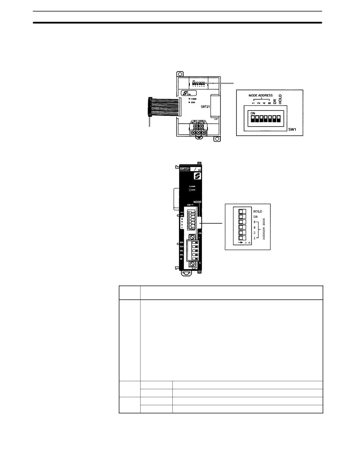
CompoBus/S I/O Link Units
Section
3-3
DIP Switch Settings
Use the DIP switch to set the CompoBus/S I/O Link Unit’s node number, commu-
nications mode, and the status of output data when a communications error oc-
curs.
CPM1A-SRT21
DIP switch
CPM2C-SRT21
Pin
Contents
labels
1, 2, 4,
Node Address Setting
and 8
Pins
Pins
Address
8421
Address
8421
0
0000
8
1000
1
0001
9
1001
2
0010
10
1010
3
0011
11
1011
4
0100
12
1100
5
0101
13
1101
6
0110
14
1110
7
0111
15
1111
1 = ON, 0 = OFF
DR
ON
Long-distance communications mode (See note 2.)
OFF
High-speed communications mode
HOLD
ON
Retain inputs after a communications error.
OFF
Clear inputs after a communications error.
Note
1. Always turn OFF the power supply before changing the DIP switch settings.
2. Never touch the DIP switch when the Unit is operating. Static electricity may
cause operating errors.
213
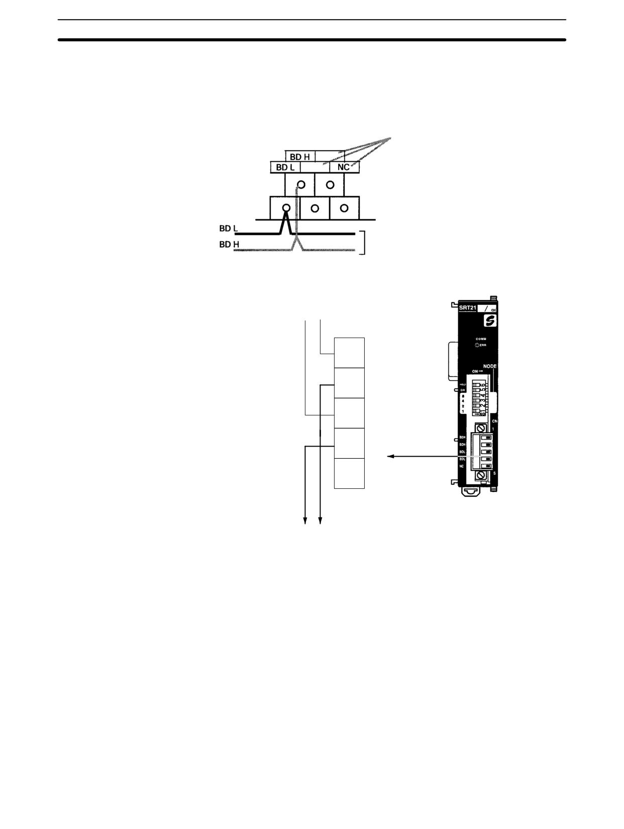
CompoBus/S I/O Link Units
Section
3-3
3. The long-distance communications mode can be used only when one of the
following
Master Units is connected: C200HW-SRM21-V1,
CQM1-SRM21-V1, or SRM1-C0j-V2.
Wiring the CompoBus/S
Wire the CompoBus/S communications path as shown in the following dia-
Communications Path
grams.
CPM1A-SRT21
These terminals are not used. They can
however be used as communications
NC (BS+)
power supply relay terminals.
NC (BS-)
(BS +)
(BS -)
Connect the CompoBus/S Communications Cable.
CPM2C-SRT21
From the CompoBus/S
communications path
BD L
BD H
BD H
BD H
BD L
BD L
NC
To the CompoBus/S
communications path
214
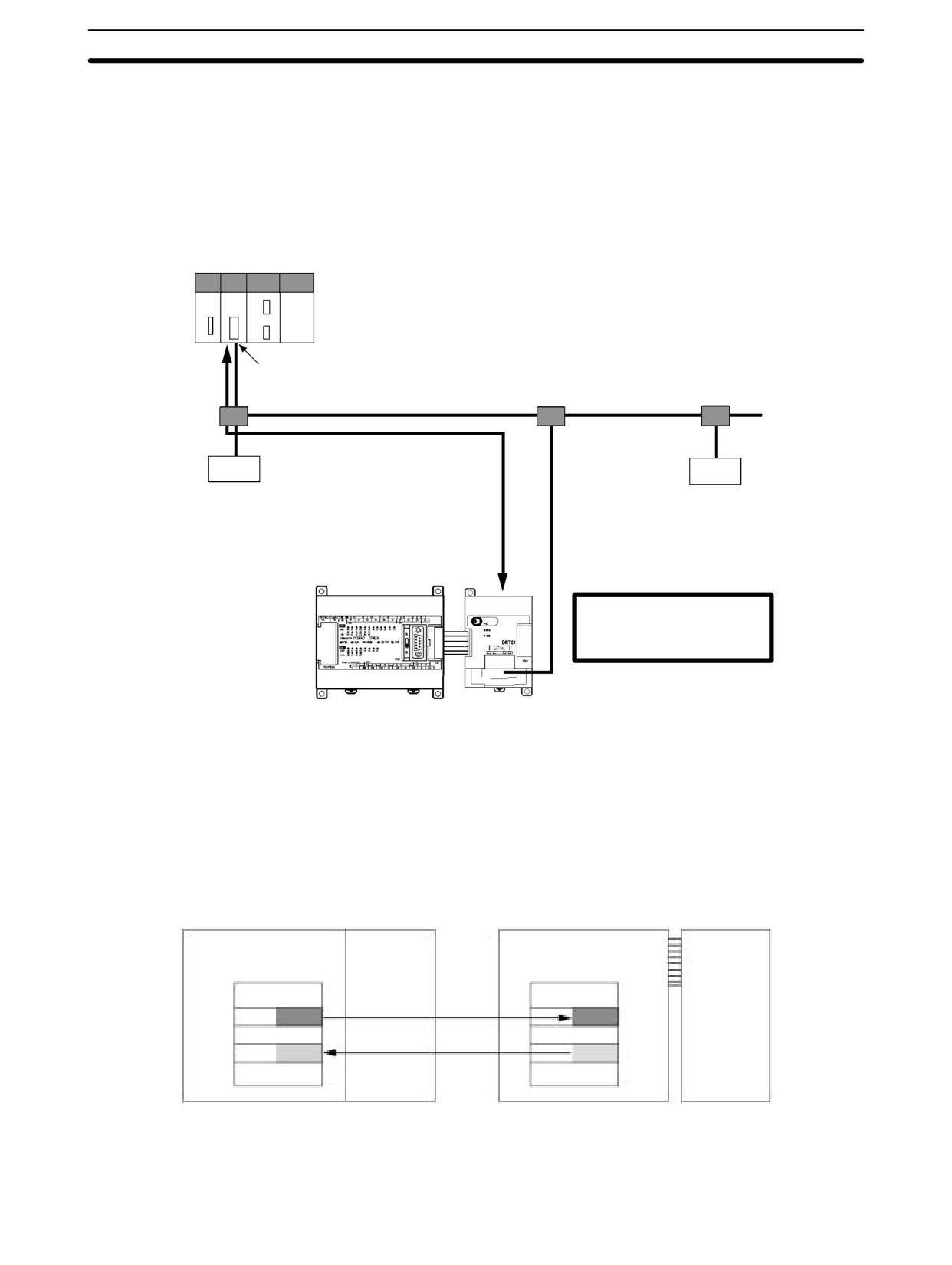
DeviceNet I/O Link Unit
Section
3-4
3-4
DeviceNet I/O Link Unit
The CPM1A or CPM2A PCs can function as slaves to a DeviceNet master when
a DeviceNet I/O Link Unit is connected. The DeviceNet I/O Link Unit establishes
an I/O link of 32 inputs and 32 outputs between the master and the PC.
A maximum of 3 DeviceNet I/O Link Units, can be connected to a CPM2A or
CPM1A to create I/O Links for up to 192 points (96 inputs and 96 outputs).
PC supporting DeviceNet master,
e.g., CS1, C200HX/HG/HE (-Z),
CVM1, CV-series, etc.
DeviceNet Master Unit
or DeviceNet Unit
DeviceNet transmission path
DeviceNet slave
DeviceNet slave
Each Unit enables remote I/O
communications for 32 input
and 32 output points as a De-
viceNet slave.
CPM1A or CPM2A
CPM1A-DRT21
CPU Unit
DeviceNet I/O Link Unit
From the standpoint of the CPU Unit, the 32 input bits and 32 output bits allo-
cated to the DeviceNet I/O Link Unit are identical to input and output bits allo-
cated to Expansion I/O Units even though the DeviceNet I/O Link Unit does not
control external inputs and outputs. The input and output bits allocated to the
DeviceNet I/O Link Unit are one side of an I/O link between the slave CPU Unit
and the CPU Unit to which the Master Unit is connected.
Master PC (CS1 Series with fixed allocations)
CPM1A or CPM2A
CPU Unit
DeviceNet
CPU Unit with 30 I/O points
DeviceNet
Master Unit
I/O Link Unit
I/O memory
I/O memory
Unit No. 0
Node
32 bits
32 bits
Inputs
Outputs
number:
IR 002
CIO 50
0
IR 003
CIO 51
32 bits
32 bits
Inputs
Output
CIO 350
IR 012
CIO 351
IR 013
Note Refer to the DeviceNet Slaves Operation Manual (W347) for details on Device-
Net networks.
215
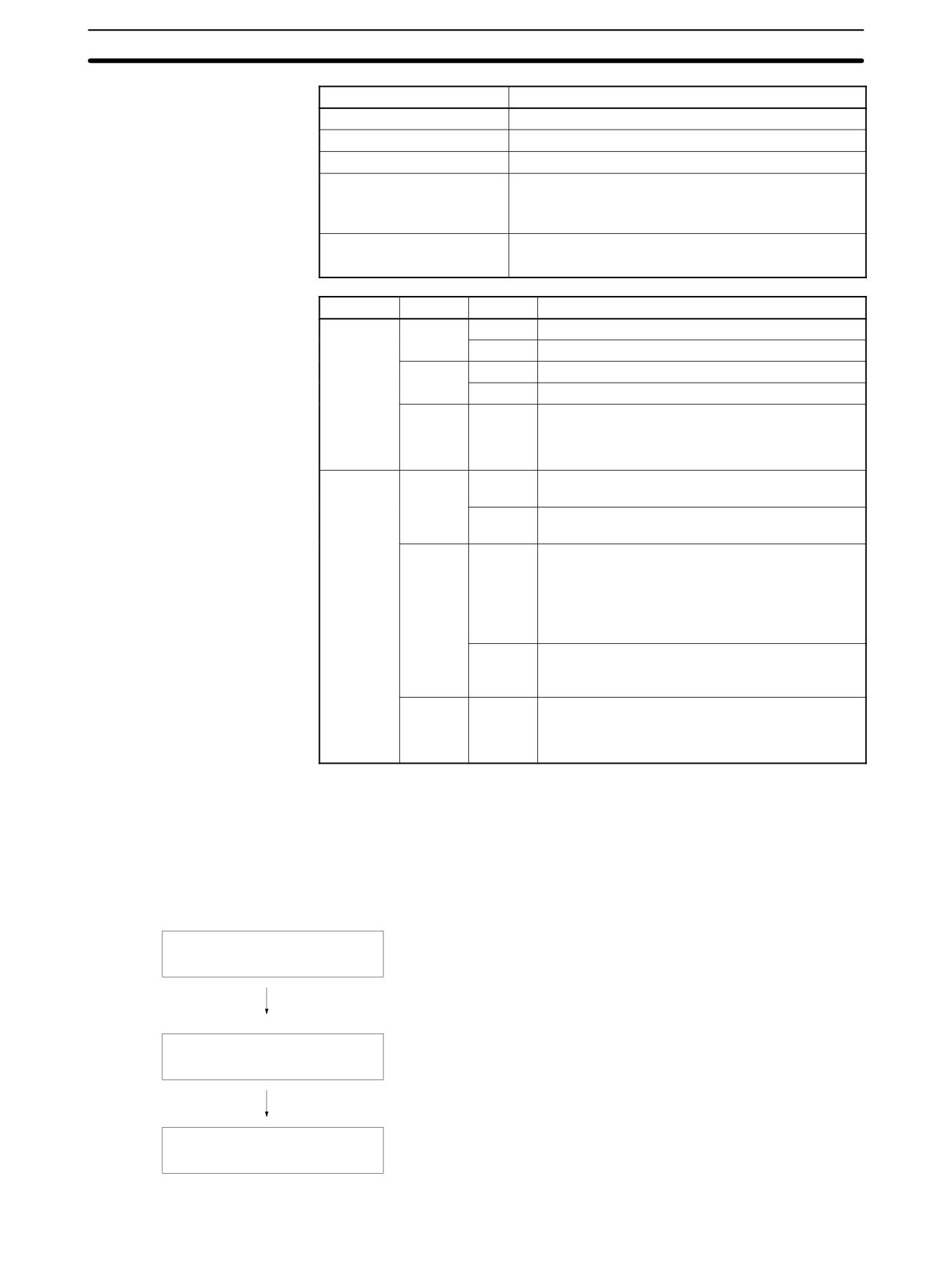
DeviceNet I/O Link Unit
Section
3-4
Specifications
Item
Specification
Model number
CPM1A-DRT21
Master/slave
DeviceNet Slave
Number of I/O points
32 input points, 32 output points
Number of words allocated
2 input words, 2 output words
in CPU Unit I/O memory
(Allocated in the same way as Expansion I/O Units
and other Expansion Units)
Node number setting
Set using the rotary switches
(Set before turning ON the CPU Unit’s power supply.)
LED Indicators
Indicator
Color
Status
Meaning
MS
Green
Lit
Normal status
Flashing
Switch settings being read
Red
Lit
Fatal hardware error (watchdog timer)
Flashing
Nonfatal error: Incorrect switch settings.
---
OFF
Power not supplied.
Waiting for initialization to start.
Reset in progress.
NS
Green
Lit
Network normal and communications
established.
Flashing
Network normal and communications not
established.
Red
Lit
Fatal communications error: Unit has detected
network status preventing normal
communications.
Node number duplications
Bus OFF detected.
Flashing
Nonfatal communications error: Communications
timeout or communications error for one or more
slaves.
---
OFF
Waiting for node number check by master.
Switch setting error.
Power not supplied.
If an error occurs in the DeviceNet I/O Link Unit, the Error Flags in AR 0200 to
Handling Unit Errors
AR 0202 will be turned ON. The addresses of the Error Flags are in the order that
the Expansion Units are connected in the PC, with AR 0200 used for the Expan-
sion Unit closest to the CPU Unit. Use these flags in the program when it is nec-
essary to detect errors.
Usage Procedure
Connect the Unit.
Connect the DeviceNet I/O Link Unit.
The node number should be a unique number between 0 and 63.
Determine the node number of the
DeviceNet I/O Link Unit and set
Use the DIP switch to set the DeviceNet I/O Link Unit’s baud rate
the rotary switches.
and the status of output data when a communications error occurs.
Wire the DeviceNet transmission
Connect the DeviceNet I/O Link Unit to a DeviceNet trans-
path.
mission path.
216
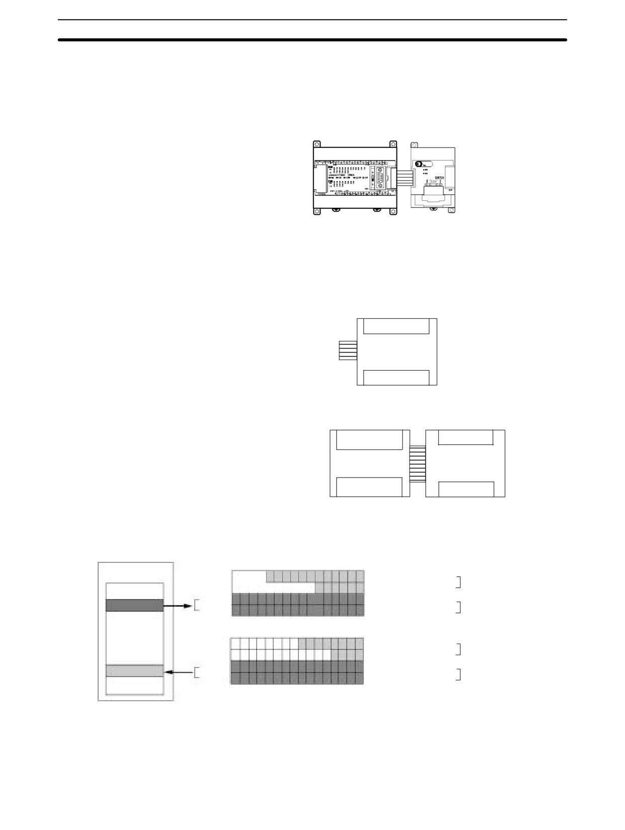
DeviceNet I/O Link Unit
Section
3-4
Connecting the
Connect the DeviceNet I/O Link Unit to the CPU Unit. Up to three Units can be
DeviceNet I/O Link Unit
connected to the CPM1A/CPM2A. When Expansion I/O Units or other Expan-
sion Units are also connected, they can be connected in any order from the CPU
Unit.
CPM1A-DRT21
DeviceNet
CPM1A/CPM2A CPU Unit
I/O Link Unit
I/O Allocation
I/O words are allocated to the DeviceNet I/O Link Unit in the same way as Expan-
sion I/O Units or other Expansion Units, the next available input and output
words are allocated. When “m” is the last allocated input word and “n” is the last
allocated output word, the DeviceNet I/O Link Unit is allocated “m+1” as its input
word and “n+1” as its output word.
DeviceNet I/O Link Unit
Word m+1 bits 00 to 15
Word m+2 bits 00 to 15
32 inputs
32 outputs
Word n+1 bits 00 to 15
Word n+2 bits 00 to 15
In the following example, a DeviceNet I/O Link Unit is connected to a CPU Unit
with 30 I/O points.
IR 000
IR 002
Input words
IR 003
IR 001
CPU Unit with
DeviceNet I/O
30 I/O points
LInk Unit
IR 010
IR 012
Output words
IR 011
IR 013
All of the words allocated to the DeviceNet I/O Link Unit are used to read and
write data between the CPU Unit of the DeviceNet I/O Link Unit and the CPU Unit
of the DeviceNet master, as shown in the following illustration.
DeviceNet master
15 14
13 12 11 10
9
8
7
6
5
4
3
2
1
0
Input bits
IR 000
I/O memory
IR 001
IR 00000 to IR 00011: 12 bits
CPU Unit
Do not use.
(m)
IR 00100 to IR 00105: 6 bits
IR 002
(m+1)
IR 00200 to IR 00215: 16 bits
DeviceNet I/O Link
32 bits
IR 003
IR 00300 to IR 00315: 16 bits
Unit
(m+2)
15 14
13 12 11 10
9
8
7
6
5
4
3
2
1
0
Output bits
IR 010
IR 011
IR 01000 to IR 01007: 8 bits
CPU Unit
(n)
IR 01100 to IR 01103: 4 bits
IR 012
(n+1)
IR 01200 to IR 01215: 16 bits
DeviceNet I/O Link
32 bits
IR 013
IR 01300 to IR 01315: 16 bits
Unit
(n+2)
The 32 bits each of I/O data are not always transmitted simultaneously. In other
words, 32 bits of data transmitted from the Master CPU Unit at the same time will
not always reach the Slave CPU Unit simultaneously, and 32 bits of data trans-
mitted from the Slave CPU Unit at the same time will not always reach the Master
CPU Unit simultaneously.
217
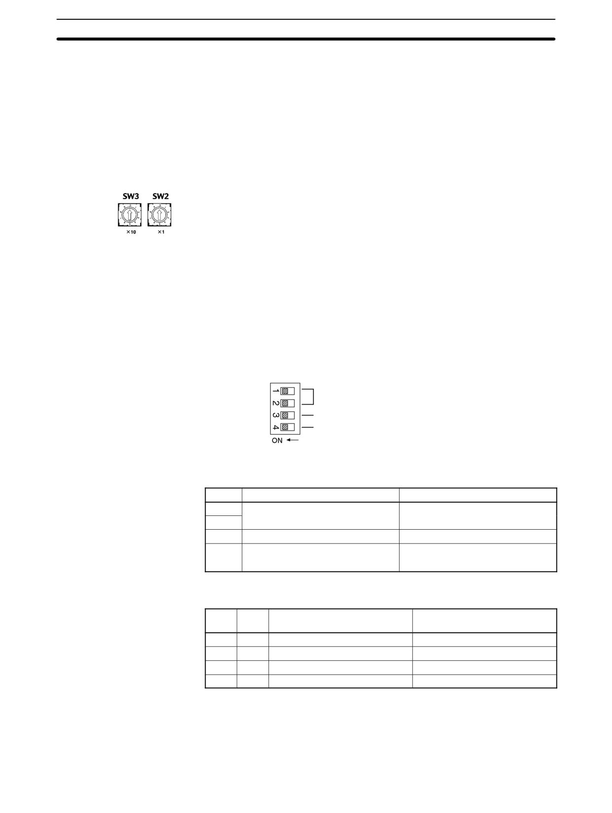
DeviceNet I/O Link Unit
Section
3-4
When the 32 bits of input data must be read together, modify the ladder program
in the CPU Unit receiving the data. For example, read the input data twice in suc-
cession and accept the data only when the two values match.
Unused bits in the DeviceNet I/O Link Unit’s output words can be used as work
bits if they are not used for output from the slave.
Unused bits in input word cannot be used as work bits.
Determining the Node Number and Making DIP Switch Settings
Node Address Switches
Use these switches to set the node address of the Unit.
Setting method: Two-digit decimal
Setting range:
0 to 63 (Do not set 64 to 99.)
Note
1. Set the rotary switches before turning ON the power supply. The switch set-
tings are read only at startup.
2. Any node address from 0 through 63 can be set as long as it hasn’t been set
on another slave node.
3. If the node address is the same as one set on another node, a node address
duplication error will occur and it won’t be possible to start up network com-
munications. Refer to the DeviceNet Slaves Operation Manual (W347) for
details.
DIP Switch
The DIP switch on the front of the DeviceNet I/O Link Unit is used to set the baud
rate and whether to hold or clear the remote outputs when a communications
error occurs in the slave.
Baud rate
Not used.
Hold/clear input for communications error (when used as a slave)
The settings of the DIP switch pins are shown in the following table. All pins are
set to OFF at the factory.
Pin
Function
Setting
1
Baud rate
See the next table.
2
3
Not used
OFF
4
Hold/clear remote outputs for
OFF:
Clear remote outputs
communications error
ON:
Hold remote outputs
Baud Rate
Pins 1 and 2 are used to set the baud rate as shown in the following table.
Pin 1
Pin 2
Baud rate
Max. transmission path length
(reference)
OFF
OFF
125 kbps
500 m
ON
OFF
250 kbps
250 m
OFF
ON
500 kbps
100 m
ON
ON
Not allowed.
---
Note
1. Always turn OFF the PC before changing the DIP switch settings.
2. Set the same baud rate on all of the nodes (Master and Slaves) in the Net-
work. Any slaves with baud rates different from the master’s rate won’t be
able to participate in communications and may cause a communications er-
ror between nodes that have been set properly.
218
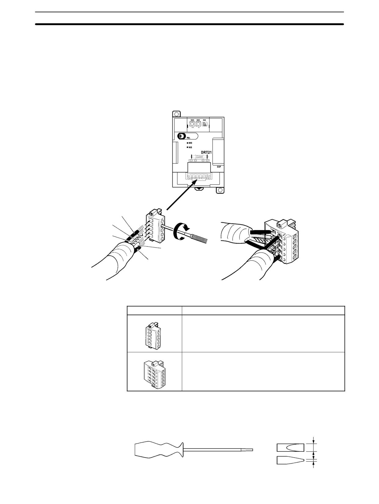
DeviceNet I/O Link Unit
Section
3-4
Hold/Clear Remote Outputs
When the DeviceNet Unit is used as a slave, pin 4 is used to set whether to hold
or clear remote outputs when a communications error occurs.
Note When using AR 02 (Expansion Unit Error Flags) in the program, turn ON pin 4 on
the DIP switch. If communications are set to be cleared, the timing for clearing
outputs and setting the Error Flags may not agree.
Wire the DeviceNet communications path as shown in the following diagram.
Wiring the DeviceNet
Communications Path
CPM1A-DRT21
DeviceNet I/O Link Unit
Connector provided with Unit
(XW4B-05C1-H1-D)
Multidrop Connector
Black (+V)
(XW4B-05C4-TF-D)
Blue (CAN high)
Shield
White (CAN low)
Red (-V)
DeviceNet Connectors
Use the following connectors.
Model
Form and specifications
XW4B-05C1-H1-D
OMRON connector with screws (included with DeviceNet I/O
Link Unit).
XW4B-05C4-TF-D
OMRON connector for multidrop connections (See note.)
Note Use the XW4B-05C4-TF-D when wiring multidrop connections using
Thick Cables.
Use the following screwdriver for the above connector.
XW4Z-00C
3.5 mm
0.6 mm
219
DeviceNet I/O Link Unit
Section
3-4
I/O Response Time
Refer to the DeviceNet Slaves Operation Manual (W347) for details on the re-
sponse time. The data read/write time for one cycle for the CPM1A-DRT21 is
approximately 0.5 ms. Add a maximum of 1 ms to the I/O response time.
220
SECTION 4
Communications Functions
This section describes how to use the communications functions provided in the CPM1, CPM1A, CPM2A, CPM2C (includ-
ing the CPM2C-S), and SRM1(-V2) PCs.
4-1
Introduction
222
4-1-1
Overview
222
4-1-2
Wiring Ports
222
4-2
CPM1/CPM1A Communications Functions
223
4-2-1
Host Link Communications
223
4-2-2
One-to-one NT Link Communications
224
4-2-3
One-to-one PC Link Communications
225
4-3
CPM2A/CPM2C Communications Functions
227
4-3-1
Host Link Communications
227
4-3-2
No-protocol Communications
247
4-3-3
One-to-one NT Link Communications
256
4-3-4
One-to-one PC Link Communications
259
4-4
SRM1(-V2) Communications Functions
264
4-4-1
Host Link Communications
264
4-4-2
No-protocol Communications
268
4-4-3
One-to-one NT Link Communications
273
4-4-4
One-to-N NT Link Communications
274
4-4-5
One-to-one PC Link Communications
275
4-5
Host Link Commands
277
4-5-1
IR/SR AREA READ - RR
277
4-5-2
LR AREA READ - RL
278
4-5-3
HR AREA READ - RH
278
4-5-4
PV READ - RC
278
4-5-5
TC STATUS READ - RG
279
4-5-6
DM AREA READ - RD
279
4-5-7
AR AREA READ - RJ
280
4-5-8
IR/SR AREA WRITE - WR
281
4-5-9
LR AREA WRITE - WL
281
4-5-10
HR AREA WRITE - WH
282
4-5-11
PV WRITE - WC
282
4-5-12
TC STATUS WRITE - WG
283
4-5-13
DM AREA WRITE - WD
284
4-5-14
AR AREA WRITE - WJ
284
4-5-15
SV READ 1 - R#
285
4-5-16
SV READ 2 - R$
286
4-5-17
SV CHANGE 1 - W#
287
4-5-18
SV CHANGE 2 - W$
288
4-5-19
STATUS READ - MS
289
4-5-20
STATUS WRITE - SC
290
4-5-21
ERROR READ - MF
291
4-5-22
FORCED SET - KS
292
4-5-23
FORCED RESET - KR
293
4-5-24
MULTIPLE FORCED SET/RESET - FK
294
4-5-25
FORCED SET/RESET CANCEL - KC
295
4-5-26
PC MODEL READ - MM
296
4-5-27
TEST - TS
296
4-5-28
PROGRAM READ - RP
297
4-5-29
PROGRAM WRITE - WP
297
4-5-30
COMPOUND COMMAND - QQ
298
4-5-31
ABORT - XZ
300
4-5-32
INITIALIZE - ::
300
4-5-33
TXD RESPONSE - EX
300
4-5-34
Undefined Command - IC
301
221
Introduction
Section
4-1
4-1
Introduction
4-1-1
Overview
CPM1/CPM1A
The CPM1/CPM1A can execute a variety of communications through its periph-
Communications
eral port via an RS-232C Adapter or an RS-422 Adapter.
Host Link Communications
The CPM1/CPM1A PCs are compatible with the Host Link System, which allows
up to 32 PCs to be controlled from a host computer. An RS-232C Adapter is used
for 1:1 communications and an RS-422 Adapter and B500-AL004 Link Adapter
are used for 1:N communications.
A CPM1/CPM1A equipped with an RS-232C Adapter can also communicate
with a OMRON Programmable Terminal using host link commands.
Refer to 4-2-1 CPM1/CPM1A Host Link Communications in this manual and
1-2-2 Host Link Communications in the CPM1 Operation Manual or 1-2-2 Host
Link Communications in the CPM1A Operation Manual for more details.
One-to-one PC Link
A data link can be created with a data area in another CPM1, CPM1A, CPM2A,
CPM2C, CQM1, C200HX/HG/HE, or C200HS PC. An RS-232C Adapter is used
to make the 1:1 connection.
Refer to 4-2-3 CPM1/CPM1A 1:1 PC Link Communications in this manual and
1-2-3 One-to-one PC Communications Links in the CPM1 Operation Manual or
1-2-3 One-to-one PC Communications Links in the CPM1A Operation Manual
for more details.
One-to-one NT Link
Using the 1:1 NT Link, the CPM1/CPM1A PC can connected to the OMRON
Programmable Terminal (NT Link Interface) through an RS-232C Adapter.
Refer to 4-2-2 CPM1/CPM1A 1:1 NT Link Communications in this manual and
1-2-4 One-to-one NT Link Communications in the CPM1 Operation Manual or
NT Link Communications in the CPM1A Operation Manual for more details.
CPM2A/CPM2C
The following types of communications can be executed through the ports of the
Communications
CPM2A/CPM2C.
• Host Link communications with a host computer
• RS-232C communications with a computer or other device
• One-to-one PC Link communications with another PC
• One-to-one NT Link communications with OMRON Programmable Terminals
This section explains the required PC Setup and methods for using these types
of communications.
SRM1(-V2) Communications
The following types of communications can be executed through the ports of the
SRM1(-V2).
• Host Link communications with a host computer
• RS-232C communications with a computer or other device
• One-to-one PC Link communications with another PC
• One-to-one NT Link communications with OMRON Programmable Terminals
Note
One-to-one NT Link communications are not possible with the SRM1-C01,
which is equipped with only a peripheral port. The SRM1-C01 may be connected
to a PT through an RS-232C Adapter in Host Link mode.
4-1-2
Wiring Ports
Refer to the CPM1 Operation Manual, CPM1A Operation Manual, CPM2A Op-
eration Manual, CPM2C Operation Manual, or SRM1 Master Control Units Op-
eration Manual for information on wiring the communications ports.
222

CPM1/CPM1A Communications Functions
Section
4-2
4-2
CPM1/CPM1A Communications Functions
4-2-1
Host Link Communications
Host Link communications were developed by OMRON for the purpose of con-
necting PCs and one or more host computers by RS-232C cable, and controlling
PC communications from the host computer. Normally the host computer issues
a command to a PC, and the PC automatically sends back a response. Thus the
communications are carried out without the PCs being actively involved. The
PCs also have the ability to initiate data transmissions when direct involvement
is necessary.
In general, there are two means for implementing Host Link communications.
One is based on C-mode commands, and the other on FINS (CV-mode) com-
mands. The CPM1/CPM1A supports C-mode commands only. For details on
Host Link communications, refer to 4-5 Host Link Commands.
PC Setup Settings
The CPM1/CPM1A’s peripheral port settings must be set properly in order to use
the Host Link communications, as shown in the following table.
Word
Bit
Function
Setting
DM 6650
00 to 07
Port settings1
00
00: Standard (1 start bit, 7-bit data, 2 stop bits, even parity, 9,600 bps)
01: Settings in DM 6651
08 to 11
Link area for 1:1 PC Link via peripheral port
0
0: LR 00 to LR 15
(Any val-
ue is OK)
12 to 15
Communications mode1
0
0: Host Link; 2: 1:1 PC Link Slave; 3: 1:1 PC Link Master; 4: 1:1 NT Link
DM 6651
00 to 07
Baud rate1
00
00: 1.2K, 01: 2.4K, 02: 4.8K, 03: 9.6K, 04: 19.2K
(Any val-
ue is OK)
08 to 15
Frame format1
00
Start
Length
Stop
Parity
(Any val-
00:
1 bit
7 bits
1 bit
Even
ue is OK)
01:
1 bit
7 bits
1 bit
Odd
02:
1 bit
7 bits
1 bit
None
03:
1 bit
7 bits
2 bit
Even
04:
1 bit
7 bits
2 bit
Odd
05:
1 bit
7 bits
2 bit
None
06:
1 bit
8 bits
1 bit
Even
07:
1 bit
8 bits
1 bit
Odd
08:
1 bit
8 bits
1 bit
None
09:
1 bit
8 bits
2 bit
Even
10:
1 bit
8 bits
2 bit
Odd
11:
1 bit
8 bits
2 bit
None
DM 6652
00 to 15
Transmission delay (Host Link)1
0000
0000 to 9999: In ms.
DM 6653
00 to 07
Node number (Host Link)1
00 to 31
00 to 31 (BCD)
08 to 15
Not used.
00
(Any val-
ue is OK)
Note
1. If an improper setting is used, a non-fatal error will occur, AR 1302 will be
turned ON, and the default setting (0, 00, or 0000) will be used.
2. For information on the Host Link settings for another OMRON PC, refer to
that PC’s Operation Manual.
223
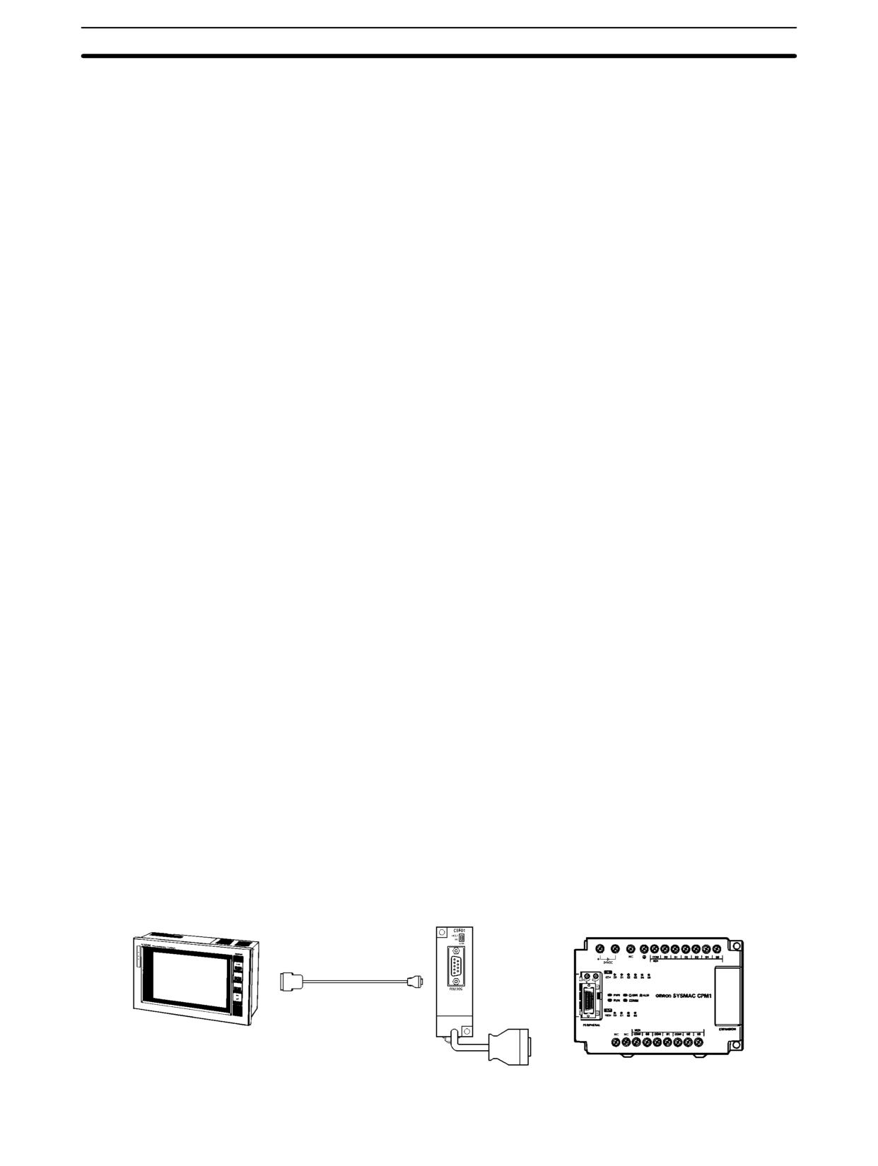
CPM1/CPM1A Communications Functions
Section
4-2
3. If an out-of-range value is set, the following communications conditions will
result. In that case, reset the value so that it is within the permissible range.
Communications mode:
Host Link
Communications format: Standard settings
(1 start bit, 7-bit data; 2 stop bits, even parity,
9,600 bps)
Transmission delay:
No
Node number:
00
Example Program
This example shows a BASIC program that reads the status of the CPM1’s in-
puts in IR 000. For more details, refer to 4-5 Host Link Commands.
An FCS (frame check sequence) check isn’t performed on the received re-
sponse data in this program. Be sure that the host computer’s RS-232C port is
configured correctly before executing the program.
1010 ’CPM1 SAMPLE PROGRAM
1020 ’SET THE COMMAND DATA
1030 S$=”@00RR00000001”
1040 FCS=0
1050 FOR I=1 TO LEN(S$)
1060 FCS=FCS XOR ASC(MID$(S$,I,1))
1070 NEXT I
1080 FCS$=(FCS):IF LEN(FCS$)=1 THEN FCS$=”0”+FCS$
1090 CLOSE 1
1100 CLS
1110 PRINT ”SENDING COMMAND”
1120 OPEN ”COM:E73” AS #1
1130 PRINT #1,S$ + FCS + CHR$(13);
1140 CLS
1150 PRINT ”RECEIVING RESPONSE DATA”
1160 LINE INPUT #1,A$
1170 PRINT A$
1180 END
4-2-2
One-to-one NT Link Communications
Using the 1:1 NT Link, the CPM1/CPM1A PC can connected to the Program-
mable Terminal (NT Link Interface) through an RS-232C Adapter.
CPM1 PCs
OMRON Programmable Terminal
RS-232C Adapter
CPM1 CPU Unit
CPM1 CPU
RS-232C Cable
224
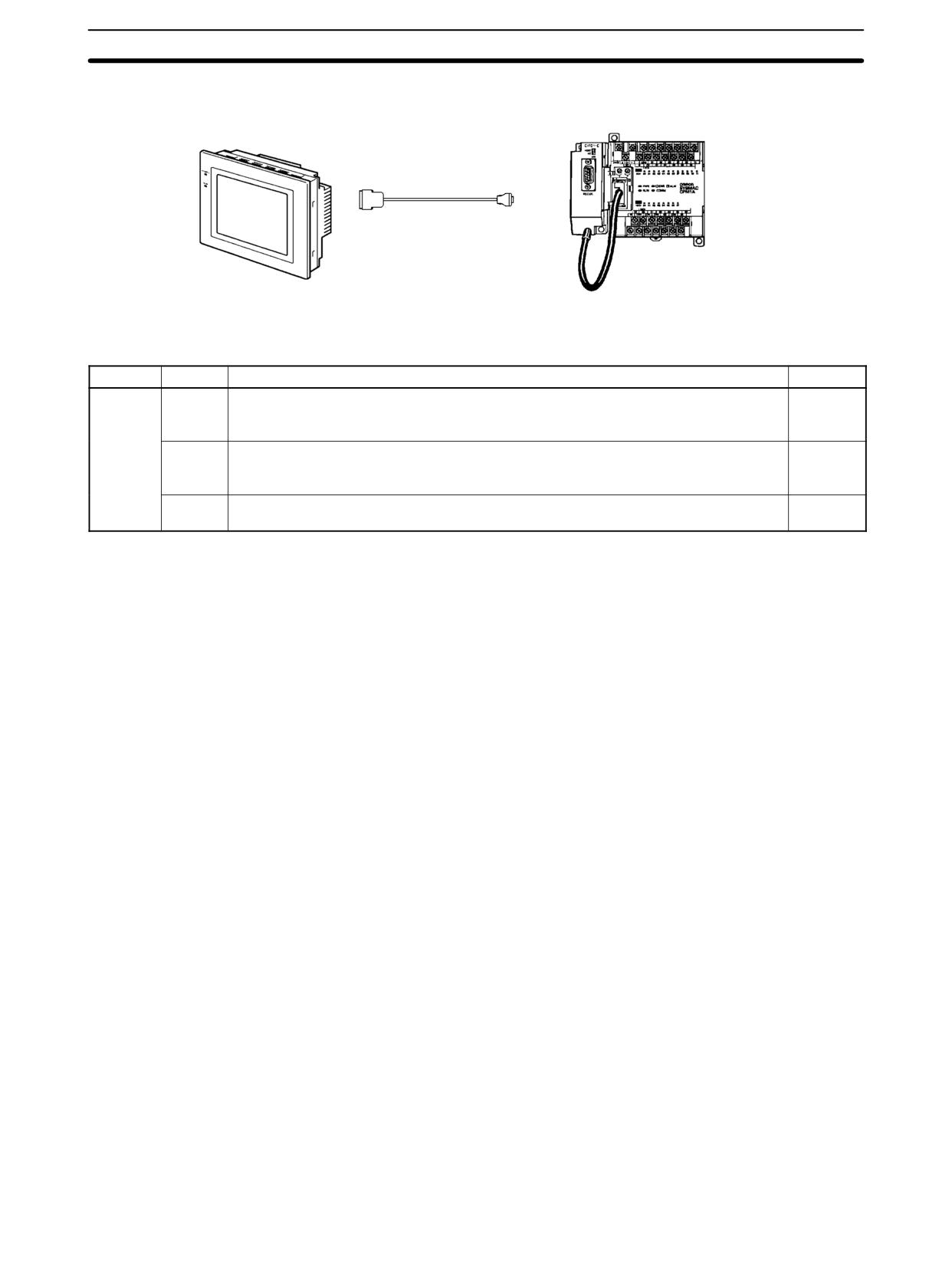
CPM1/CPM1A Communications Functions
Section
4-2
CPM1A PCs
RS-232C
OMRON Programmable Terminal
Adapter
CPM1A CPU Unit
RS-232C Cable
PC Setup Settings
The settings relating to 1:1 NT Link PC communications must be set as shown in
the following table.
Word
Bit
Function
Setting
DM 6650
00 to 07
Port settings1
00
00: Standard (1 start bit, 7-bit data, 2 stop bits, even parity, 9,600 bps)
(Any val-
01: Settings in DM 6651
ue is OK)
08 to 11
Link area for 1:1 PC Link via peripheral port
0
0: LR 00 to LR 15
(Any val-
ue is OK)
12 to 15
Communications mode1
4
0: Host Link; 2: 1:1 PC Link Slave; 3: 1:1 PC Link Master; 4: 1:1 NT Link
Note
1. If an improper setting is used, a non-fatal error will occur, AR 1302 will be
turned ON, and the default setting (0 or 00) will be used.
2. For information on the NT Link settings for another OMRON PC, refer to that
PC’s Operation Manual.
3. If an out-of-range value is set, the following communications conditions will
result. In that case, reset the value so that it is within the permissible range.
Communications mode:
Host Link
Communications format:
Standard settings
(1 start bit, 7-bit data; 2 stop bits, even parity,
9,600 bps)
Transmission delay:
No
Node number:
00
4-2-3
One-to-one PC Link Communications
In a 1:1 PC Link, a CPM1/CPM1A is linked to another CPM1/CPM1A, CPM2A/
CPM2C, CQM1, C200HX/HG/HE, or C200HS PC through an RS-232C Adapter
and standard RS-232C cable. One of the PCs will serve as the Master and the
other as the Slave. The 1:1 PC Link can connect up to 256 bits (LR 0000 to LR
1515) in the two PCs.
225
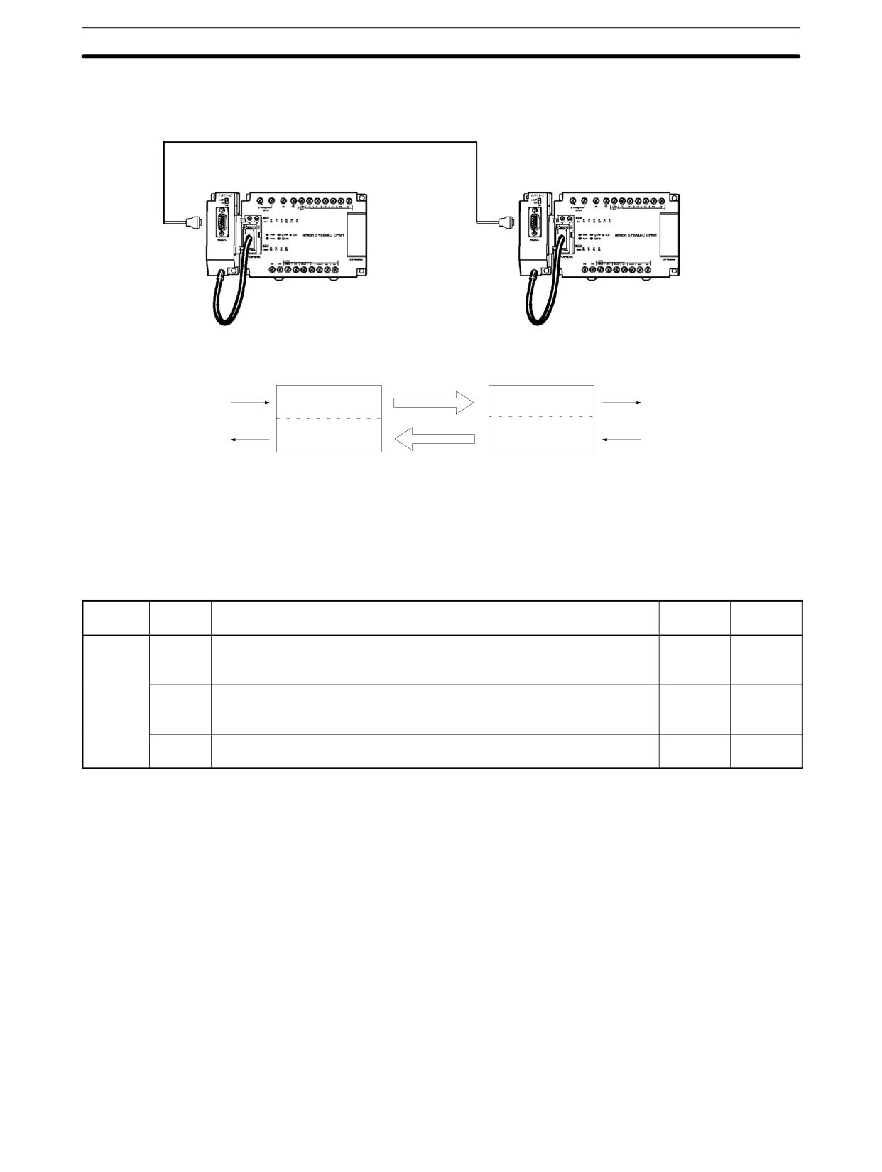
CPM1/CPM1A Communications Functions
Section
4-2
CPM1/CPM1A One-to-one
The following diagram shows a 1:1 PC Link between two CPM1s PCs. Refer to
PC Links
the CPM1A Operation Manual for the corresponding information on the CPM1A.
RS-232C Cable
RS-232C Adapter
RS-232C Adapter
CPM1 CPU Unit
CPM1 CPU Unit
The words used for the 1:1 PC Link are as shown below.
Master
Slave
LR00
LR00
Write data
Area for writing
Area for reading
Read data
LR07
LR07
LR08
LR08
Read data
Area for reading
Area for writing
Write data
LR15
LR15
Limitations of 1:1 PC Links
Only the 16 LR words from LR 00 to LR 15 can be linked in the CPM1/CPM1A, so
with a CPM1/CPM1A
use only those 16 words in the CQM1 or C200HS when making a 1:1 PC Link
with one of those PCs. A 1:1 PC Link cannot be made to a CPM1/CPM1A PC
using LR 16 through LR 63 in the CQM1, C200HX/HG/HE, or C200HS.
PC Setup Settings
The settings relating to 1:1 PC Link communications must be set as shown in the
following table.
Word
Bit
Function
Setting
Setting
(Master)
(Slave)
DM 6650
00 to 07
Port settings1
00
00
00: Standard (1 start bit, 7-bit data, 2 stop bits, even parity, 9,600 bps)
(Any val-
(Any val-
01: Settings in DM 6651
ue is OK)
ue is OK)
08 to 11
Link area for 1:1 PC Link via peripheral port
0
0
0: LR 00 to LR 15
(Any val-
ue is OK)
12 to 15
Communications mode1
3
2
0: Host Link; 2: 1:1 PC Link Slave; 3: 1:1 PC Link Master; 4: 1:1 NT Link
Note
1. If an improper setting is used, a non-fatal error will occur, AR 1302 will be
turned ON, and the default setting (0 or 00) will be used.
2. For information on the 1:1 PC Link settings for another OMRON PC, refer to
that PC’s Operation Manual.
3. For information on CPM1/CPM1A 1:1 PC Link connections and wiring dia-
grams refer to 3-4-7 Host Link Connections in the CPM1 Operation Manual
or CPM1A Operation Manual. For the SRM1(-V2) refer to 3-4-4 RS-232C
Port Wiring in the SRM1 Master Control Unit Operation Manual.
4. If an out-of-range value is set, the following communications conditions will
result. In that case, reset the value so that it is within the permissible range.
Communications mode:
Host Link
Communications format:
Standard settings
(1 start bit, 7-bit data; 2 stop bits, even parity,
9,600 bps)
Transmission delay:
No
Node number:
00
226
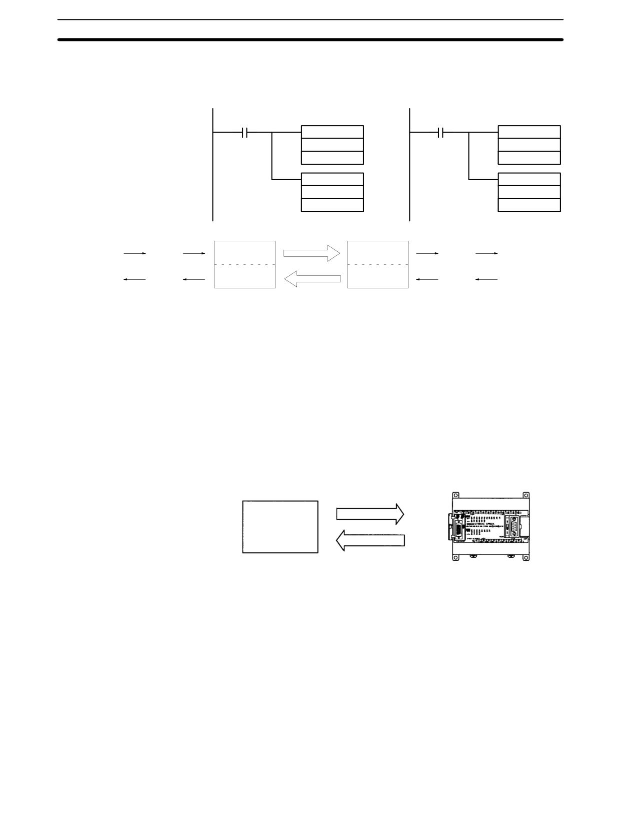
CPM2A/CPM2C Communications Functions
Section
4-3
Example Program
This example shows ladder programs that copy the status of IR 000 in each
CPM1/CPM1A to SR 200 in the other CPM1/CPM1A.
Program in the Master
Program in the Slave
25313 (Always ON)
25313 (Always ON)
MOV(21)
MOV(21)
000
000
LR00
LR08
MOV(21)
MOV(21)
LR08
LR00
200
200
LR00
LR00
IR 000
Write
Writing area
Reading area
Read
SR 200
LR07
LR07
LR08
LR08
SR 200
Read
Reading area
Writing area
Write
IR 000
LR15
LR15
4-3
CPM2A/CPM2C Communications Functions
This section describes how to use CPM2A/CPM2C (including the CPM2C-S)
communications functions. Read this section if you are using Host Link, no-pro-
tocol, 1:1 NT Link, or 1:1 PC Link communications.
4-3-1
Host Link Communications
Host Link communications are a conversational-type communications protocol,
in which the PC sends responses to commands issued from a host computer
and can be used to read or write data in the PC’s data areas and control some PC
operations. There is no need for a communications program in the PC. Host Link
communications can be used through the peripheral port or the CPM2A/
CPM2C’s RS-232C port.
CPM2A
Commands
Host computer
Responses
227
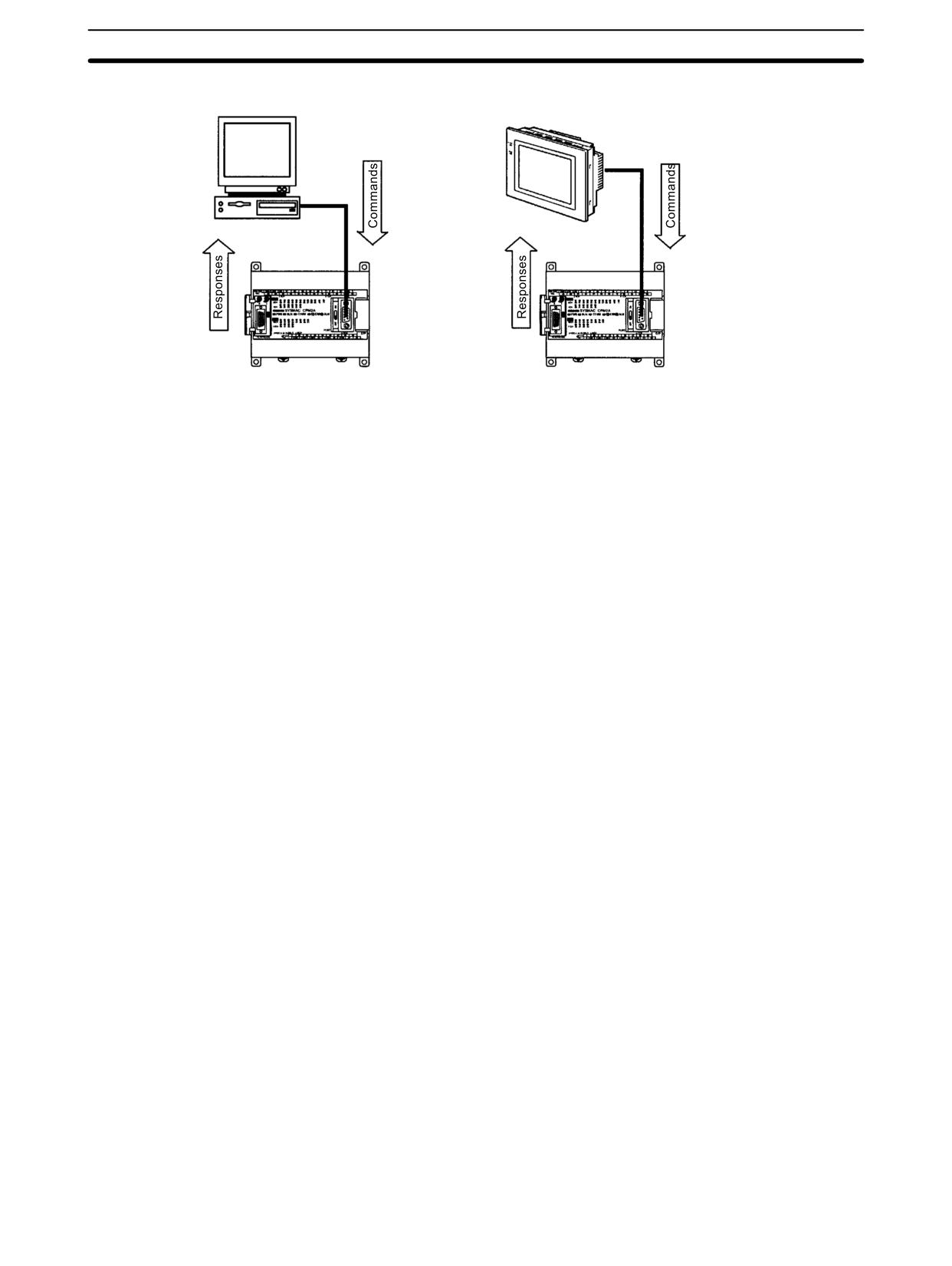
CPM2A/CPM2C Communications Functions
Section
4-3
CPM2A One-to-one Communications
OMRON Programmable
Terminal
CPM2A RS-232C port connection
CPM2A RS-232C port connection
(See note.)
(See note.)
Note When connecting to the peripheral port, an RS-232C Adapter or computer
connection cable (CQM1-CIF01 or CQM1-CIF02) is necessary.
228
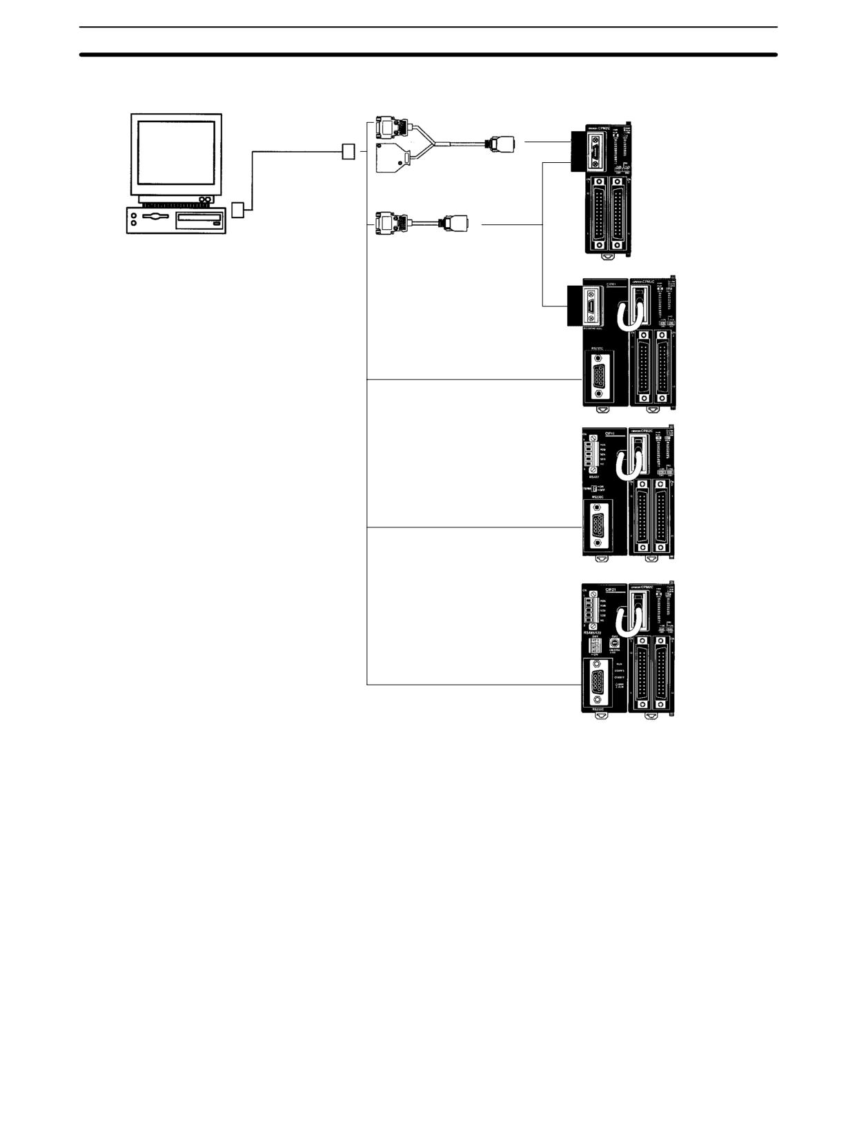
CPM2A/CPM2C Communications Functions
Section
4-3
CPM2C One-to-one Communications
Connecting Cable
RS-232C port (D-sub 9-pin)
CPM2C CPU Unit
XW2Z-200S-V (2 m)
XW2Z-500S-V (5 m)
CPM2C-CN111 (0.15 m)
IBM PC/AT
CS1W-CN118 (0.1 m)
CPM2C
or compatible
CPU Unit
CPM2C-CIF01
CPM2C
CPU Unit
CPM2C-CIF11
CPM2C
CPU Unit
CPM2C-CIF21
Note The CSW1-CN226/626 can be connected directly to the CPU Unit. They cannot
be connected to the CPM2C-CIF01.
229
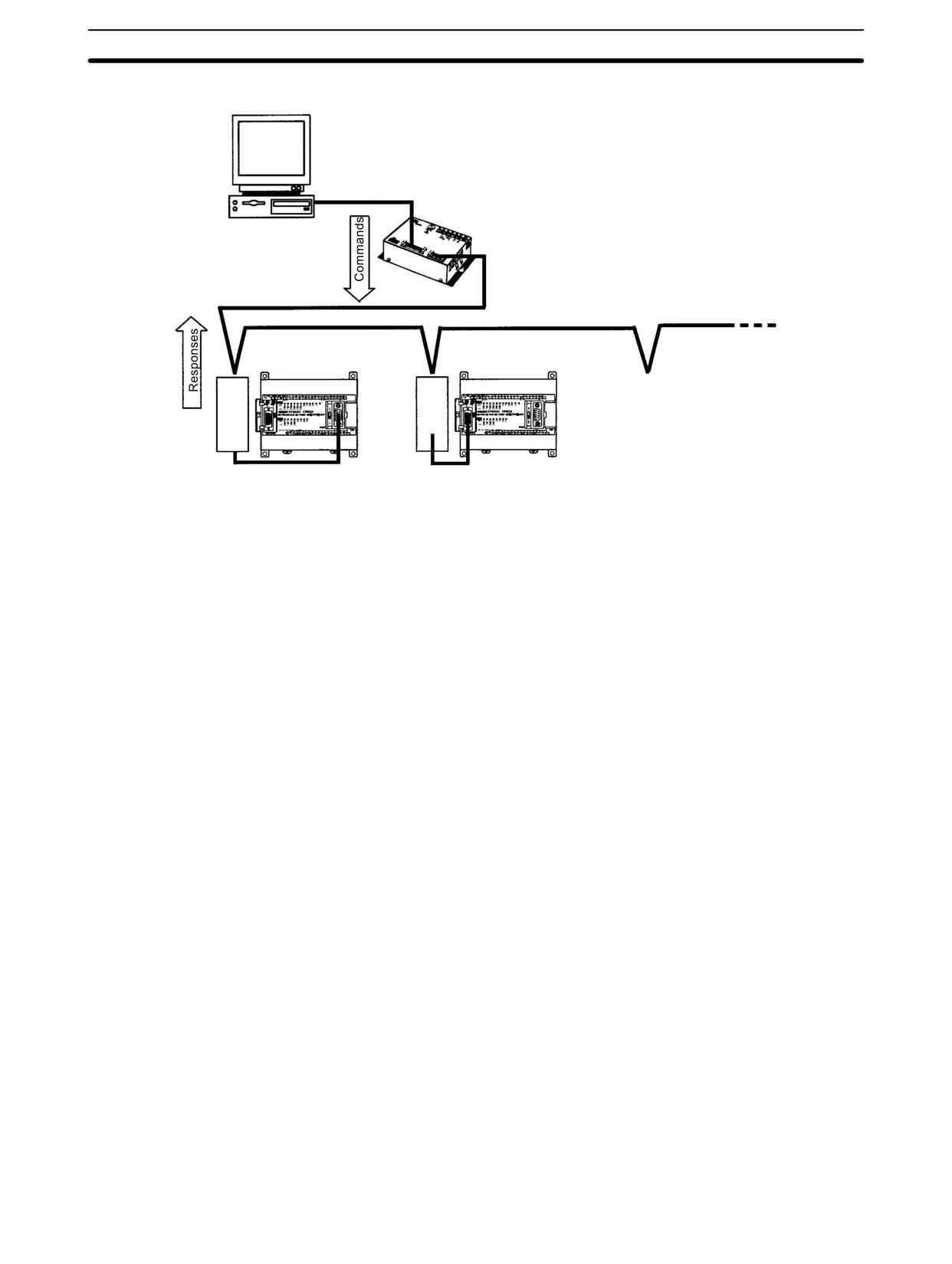
CPM2A/CPM2C Communications Functions
Section
4-3
CPM2A 1:N Communications
IBM PC/AT
B500-AL004
or compatible
Link Adapter
CPM2A RS-232C
CPM2A peripheral
port connection
port connection
NT-AL001 RS-232C/RS-422
CPM1-CIF01 RS-422 Adapter
Conversion Adapter
230
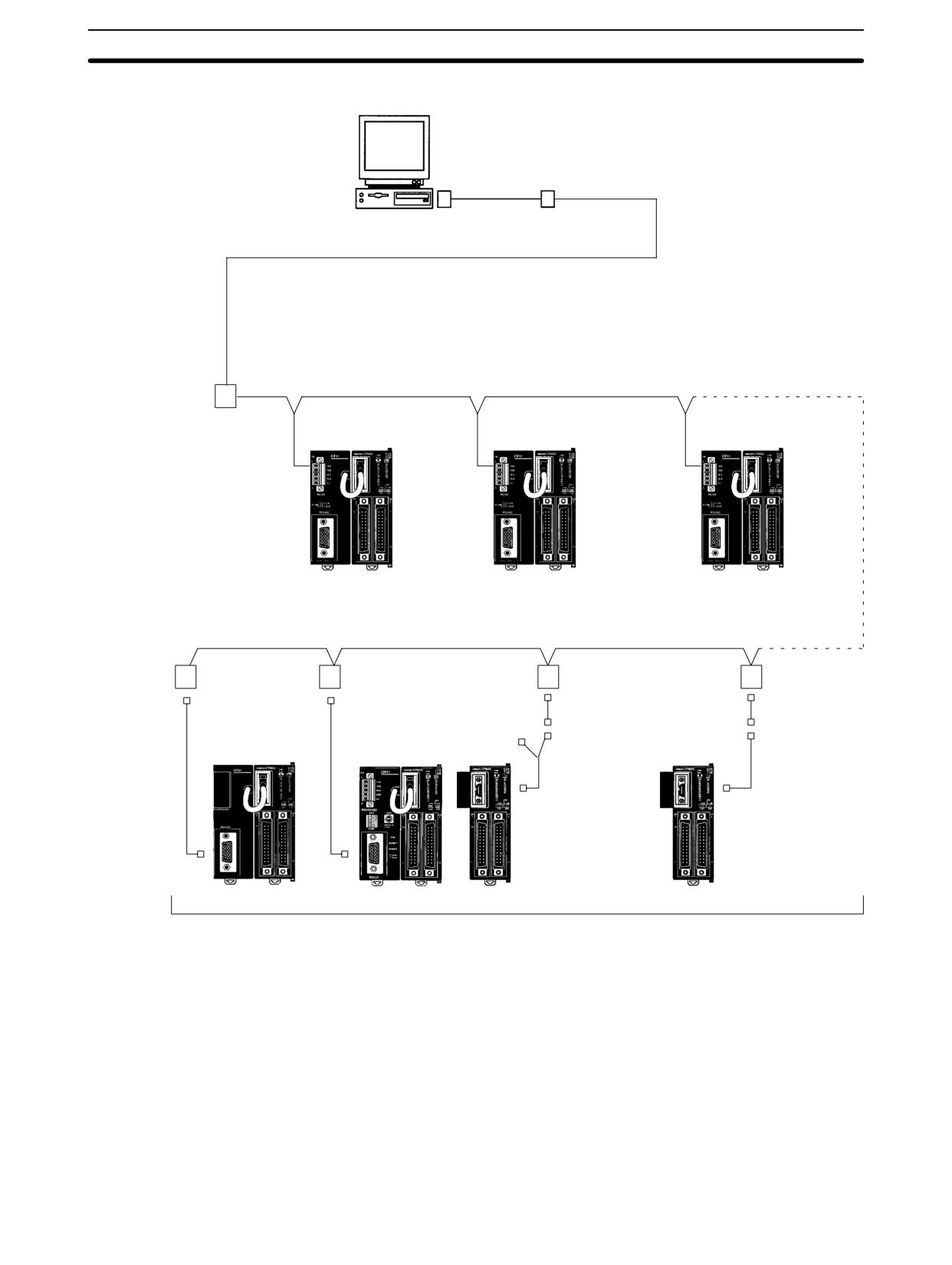
CPM2A/CPM2C Communications Functions
Section
4-3
CPM2C 1:N Communications
IBM PC/AT or
Connecting Cable
compatible
computer
XW2Z-200S-V (2 m)
XW2Z-500S-V (5 m)
B500-AL004 or NT-AL001 (requires +5 V)
(See notes 1 and 2.)
RS-422 (Total length: 500 m max.)
When using the port
as a peripheral port
CPM2C
CPM2C
CPM2C
CPU Unit
CPU Unit
CPU Unit
CPM2-CIF11
CPM2-CIF11
CPM2-CIF11
NT-AL001
NT-AL001
When using
NT-AL001
NT-AL001
(See note 1.)
(See note 1.)
the port as
(See note 1.)
(See note 1.)
XW2Z-070T-1 (0.7 m)
an RS-232C
XW2Z-200T-1 (2 m)
RS-232C port
XW2Z-070T-1 (0.7 m)
XW2Z-070T-1 (0.7 m)
port
XW2Z-200T-1 (2 m)
XW2Z-200T-1 (2 m)
CPM2C
CPM2C
CPM2C
RS-232C port
CPM2C
RS-232C port
CPU Unit
CPU Unit
CPU Unit
CPU Unit
XW2Z-070T-1 (0.7 m)
CPM2C-CN111
CSW1-CN118 Con-
XW2Z-200T-1 (2 m)
Connecting Cable
necting Cable (0.1 m)
(0.15 m)
CPM2C-CIF01
CPM2C-CIF21
Up to 32 PCs
231
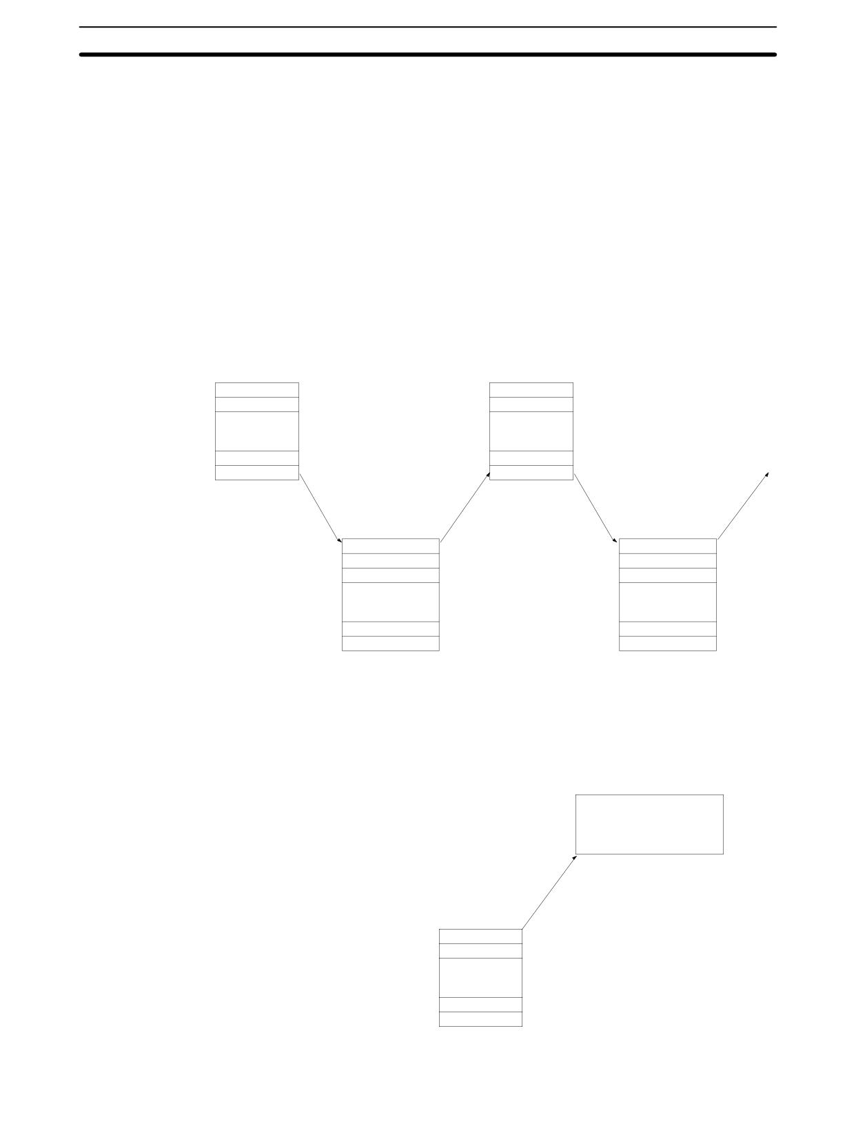
CPM2A/CPM2C Communications Functions
Section
4-3
Frame Transmission and Reception
In Host Link communications, the host computer ordinarily has the transmission
right first and initiates the communications. The CPM2A/CPM2C then automati-
cally sends a response.
Commands and responses are exchanged in the order shown in the illustration
below. The block of data transferred in a single transmission is called a “frame.”
A single frame is configured of a maximum of 131 characters of data. The right to
send a frame is called the “transmission right.” The Unit that has the transmis-
sion right is the one that can send a frame at any given time. The transmission
right is traded back and forth between the host computer and the CPM2A/
CPM2C each time a frame is transmitted. The transmission right is passed from
the transmitting Unit to the receiving Unit when either a terminator (the code that
marks the end of a command or response) or a delimiter (the code that sets
frames apart) is received.
Frame (command)
Frame (command)
Unit no.
Unit no.
Header code
Header code
Host
computer
Text
Text
FCS
FCS
Terminator
Terminator
Next frame transmission
enabled (i.e., transmission
right transferred)
Unit no.
Unit no.
Header code
Header code
End code
End code
CPM2A/CPM2C
Text
Text
FCS
FCS
Terminator
Terminator
Frame (response)
Frame (response)
Data transmissions from the PC to the host computer can be initiated by the CPU
Slave-initiated
Communications
Unit using TXD(48).
Host
There is no response
computer
from the host computer
Unit no.
Header code
CPM2A/CPM2C
Text
FCS
Terminator
Frame (response)
232
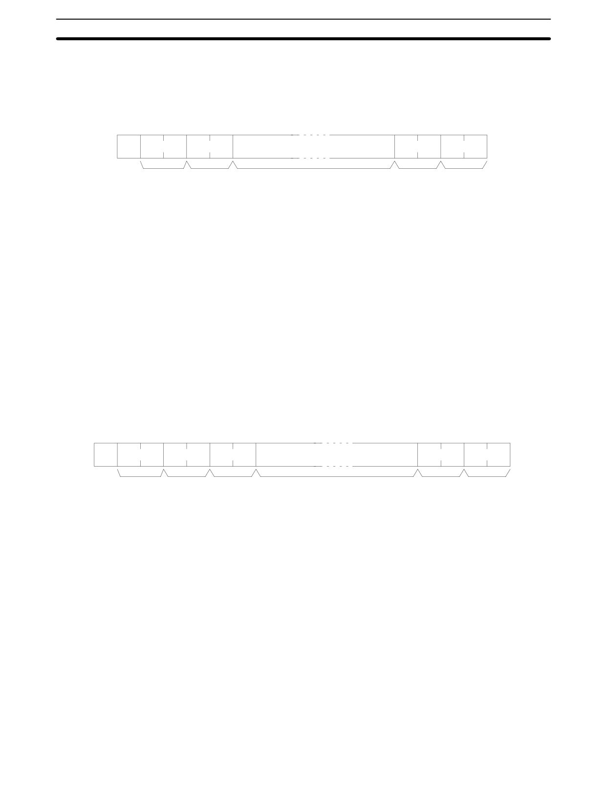
CPM2A/CPM2C Communications Functions
Section
4-3
Command and Response Formats
This section explains the formats for the commands and responses that are ex-
changed in Host Link communications.
Command Format
When transmitting a command from the host computer, prepare the command
data in the format shown below.
@
x 101
x 100
*
↵
Node No.
Header
Text
FCS
Terminator
code
@
An “@” symbol must be placed at the beginning.
Node No.
Identifies the CPM2A/CPM2C PC communicating with the host computer.
Specify the CPM2A/CPM2C’s node number in the PC Setup (DM 6648,
DM 6653).
Header Code
Set the 2-character command code.
Text
Set the command parameters.
FCS
Set a 2-character Frame Check Sequence code. See page 235.
Terminator
Set two characters, “*” and the carriage return (CHR$(13)) to indicate the end of
the command.
Response Format
The response from the CPM2A/CPM2C is returned in the format shown below.
Prepare a program so that the response data can be interpreted and processed.
@
x 101 x 100
x 161 x 160
*
↵
Node No.
Header
End code
Text
FCS
Terminator
code
@, Node No., Header Code
Contents identical to those of the command are returned.
End Code
The completion status of the command (e.g., whether or not an error has oc-
curred) is returned.
Text
Text is returned only when there is data such as read data.
FCS
The set 2-character Frame Check Sequence is returned.
Terminator
Set two characters, “*” and the carriage return (CHR$(13)) to indicate the end of
the response.
Long Transmissions
The largest block of data that can be transmitted as a single frame is 131 charac-
ters. A command or response of 132 characters or more must therefore be di-
vided into more than one frame before transmission. When a transmission is
split, the ends of the first and intermediate frames are marked by a delimiter
instead of a terminator.
233
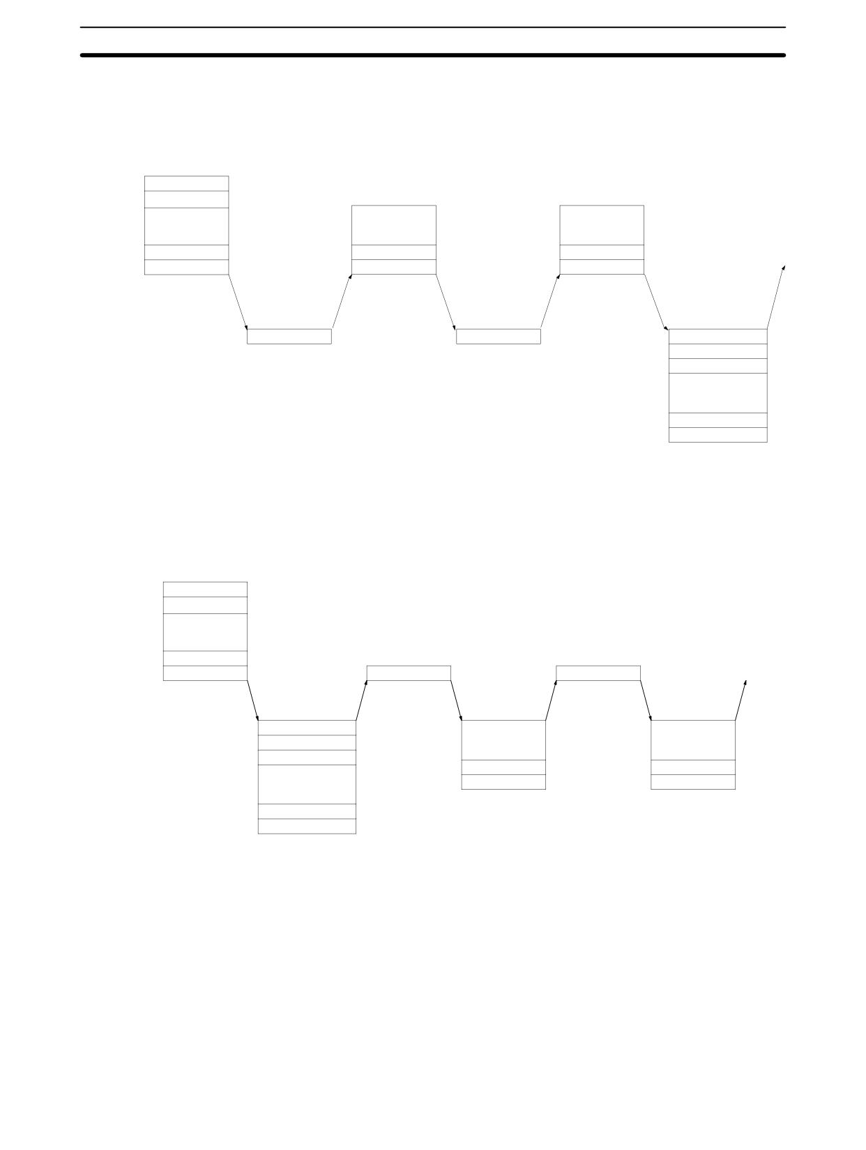
CPM2A/CPM2C Communications Functions
Section
4-3
Dividing Commands
As each frame is transmitted by the host computer, the computer waits for the
delimiter to be transmitted from the CPM2A/CPM2C. After the delimiter has
been transmitted, the next frame will then be sent. This procedure is repeated
until the entire command has been transmitted.
Frame 1 (command)
Frame 2 (command)
Frame 3 (command)
Unit no.
Header code
Host
computer
Text
Text
Text
FCS
FCS
FCS
Delimiter
Delimiter
Terminator
Delimiter
Delimiter
Unit no.
CPM2A/CPM2C
Header code
End code
Text
FCS
Terminator
Frame (response)
Dividing Responses
As each frame is received by the host computer, a delimiter is transmitted to the
CPM2A/CPM2C. After the delimiter has been transmitted, the CPM2A/CPM2C
will transmit the next frame. This procedure is repeated until the entire response
has been transmitted.
Frame (command)
Unit no.
Header code
Host
computer
Text
FCS
Terminator
Delimiter
Delimiter
Unit no.
Header code
Text
Text
End code
FCS
FCS
CPM2A/CPM2C
Text
Delimiter
Terminator
Frame2 (response)
Frame3 (response)
FCS
Delimiter
Frame1 (response)
234
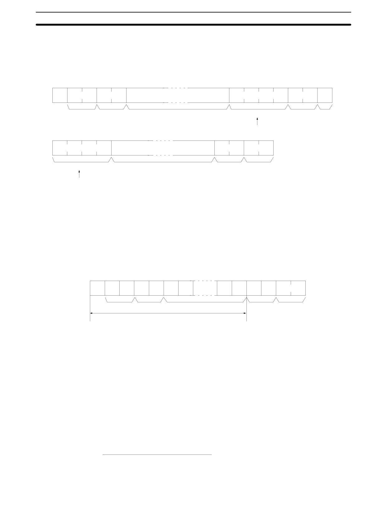
CPM2A/CPM2C Communications Functions
Section
4-3
Precautions for Long
When dividing commands such as WR, WL, WC, or WD that execute write op-
Transmissions
erations, be careful not to divide into separate frames data that is to be written
into a single word. As shown in the illustration below, be sure to divide frames so
that they coincide with the divisions between words.
Frame 1
(131 characters maximum)
@
0
0
W
D
Data
↵
x101 x100
Node
Header
One word of data
FCS
Delimiter
No.
code
Data from the same word is not divided.
Frame 2 (128 characters maximum)
Data
*
↵
One word of data
FCS
Terminator
Data from the same word is not divided.
FCS (Frame Check Sequence)
When a frame is transmitted, an FCS is placed just before the delimiter or termi-
nator in order to check whether any data error has been generated. The FCS is
8-bit data converted into two ASCII characters. The 8-bit data is the result of an
EXCLUSIVE OR performed on the data from the beginning of the frame until the
end of the text in that frame (i.e., just before the FCS). Calculating the FCS each
time a frame is received and checking the result against the FCS that is included
in the frame makes it possible to check for data errors in the frame.
@
1
0
R
R
0
0
0
1
4
2
*
↵
Node No. Header code
Text
FCS
Terminator
FCS calculation range
ASCII code
Leftmost
Rightmost
@
→
40
→
0100
0000
XOR
1
→
31
→
0011
0001
XOR
0
→
30
→
0011
0000
XOR
R
→
52
→
0101
0010
XOR
0
→
30
→
0011
0000
XOR
0
→
30
→
0011
0000
XOR
to
0
→
30
→
0011
0000
XOR
1
→
31
→
0011
0001
Calculation results
0100
0010
↓
↓
Converted to hexadecimal.
4
2
Handled as ASCII characters.
235
CPM2A/CPM2C Communications Functions
Section
4-3
Example Program for
This example shows a BASIC subroutine program for executing an FCS check
FCS
on a frame received by the host computer.
Normal reception data includes the FCS, delimiter or terminator, and so on.
When an error occurs in transmission, however the FCS or some other data may
not be included. Be sure to program the system to cover this possibility.
----------------------------------------------------------------------------
400 *FCSCHECK
410 L = LEN ( RESPONSE$ ) ’ .
Data transmitted and received
420 Q = 0 : FCSCK$ = ” ”
430 A$ = RIGHT$ ( RESPONSE$ , 1)
440 PRINT RESPONSE$ , A$ , L
450 IF A$ = ”*” THEN LENGS = LEN ( RESPONSE$ ) - 3
ELSE LENGS = LEN ( RESPONSE$ ) - 2
460 FCSP$ = MID$ ( RESPONSE$ , LENGS + 1 , 2 ) ’ .
FCS data received
470 FOR I = 1 TO LENGS ’ .
Number of characters in FCS
480
Q = ASC ( MID$ ( RESPONSE$ , I , 1 ) ) XOR Q
490 NEXT I
500 FCSD$ = HEX$ ( Q )
510 IF LEN ( FCS0$ ) = 1 THEN FCSD$ = ” 0 ” + FCSD$ ’ .
FCS result
520 IF FCSD$ < > FCSP$ THEN FCSCK$ = ” ERR ”
530 PRINT ” FCSD$ = ” ; FCSD$ , ” FCSP$ = ” ; FCSP$ , ” FCSCK$ = ” ; FCSCK$
540 RETURN
----------------------------------------------------------------------------
236

CPM2A/CPM2C Communications Functions
Section
4-3
Commands
Header
CPM2A/CPM2C Operating Mode
Name
Page
cod
e
RUN
MONITOR
PROGRAM
RR
Valid
Valid
Valid
IR/WR/SR AREA READ
277
RL
Valid
Valid
Valid
LR AREA READ
278
RH
Valid
Valid
Valid
HR AREA READ
278
RC
Valid
Valid
Valid
TC PV READ
278
RG
Valid
Valid
Valid
TC STATUS READ
279
RD
Valid
Valid
Valid
DM AREA READ
279
RJ
Valid
Valid
Valid
AR AREA READ
280
WR
Not Valid
Valid
Valid
IR/WR/SR AREA WRITE
281
WL
Not Valid
Valid
Valid
LR AREA WRITE
281
WH
Not Valid
Valid
Valid
HR AREA WRITE
282
WC
Not Valid
Valid
Valid
TC PV WRITE
282
WG
Not Valid
Valid
Valid
TC STATUS WRITE
283
WD
Not Valid
Valid
Valid
DM AREA WRITE
284
WJ
Not Valid
Valid
Valid
AR AREA WRITE
284
R#
Valid
Valid
Valid
SV READ 1
285
R$
Valid
Valid
Valid
SV READ 2
286
W#
Not Valid
Valid
Valid
SV CHANGE 1
287
W$
Not Valid
Valid
Valid
SV CHANGE 2
288
MS
Valid
Valid
Valid
STATUS READ
289
SC
Valid
Valid
Valid
STATUS WRITE
290
MF
Valid
Valid
Valid
ERROR READ
291
KS
Not Valid
Valid
Valid
FORCED SET
292
KR
Not Valid
Valid
Valid
FORCED RESET
293
FK
Not Valid
Valid
Valid
MULTIPLE FORCED SET/RESET
294
KC
Valid
Valid
Valid
FORCED SET/RESET CANCEL
295
MM
Valid
Valid
Valid
PC MODEL READ
296
TS
Valid
Valid
Valid
TEST
296
RP
Valid
Valid
Valid
PROGRAM READ
297
WP
Not Valid
Not Valid
Valid
PROGRAM WRITE
297
QQ
Valid
Valid
Valid
COMPOUND COMMAND
298
XZ
Valid
Valid
Valid
ABORT (command only)
300
**
Valid
Valid
Valid
INITIALIZE (command only)
300
EX
Valid
Valid
Not Valid
TXD RESPONSE (response only)
300
IC
---
---
---
Undefined command (response only)
301
Note ---: Not affected by the mode.
237
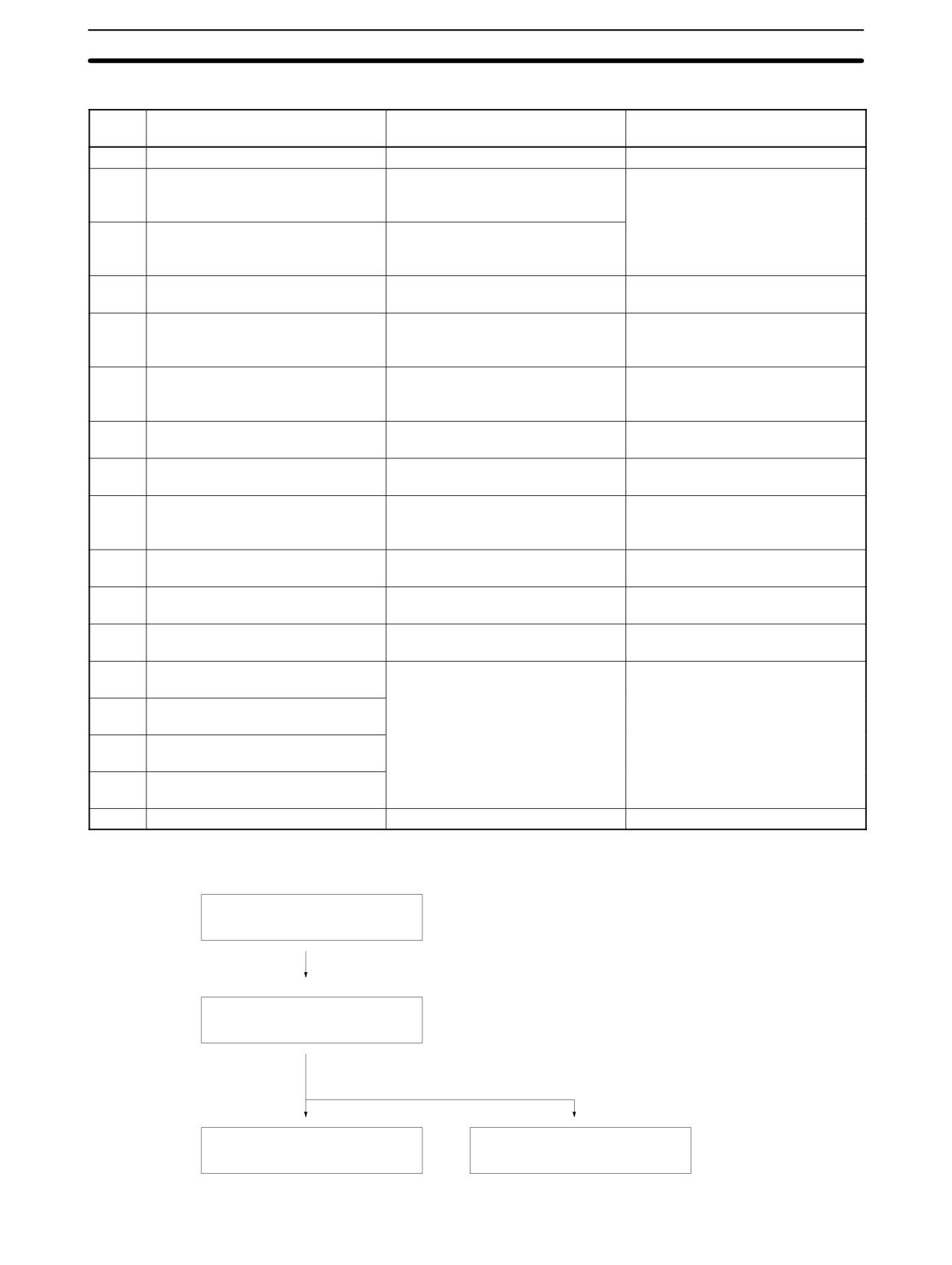
CPM2A/CPM2C Communications Functions
Section
4-3
Response Codes
End
Contents
Probable cause
Corrective measures
code
00
Normal completion
---
---
01
Not executable in RUN mode
The command that was sent can-
Check the relation between the
not be executed when the PC is in
command and the PC mode.
RUN mode.
02
Not executable in MONITOR mode
The command that was sent can-
not be executed when the PC is in
MONITOR mode.
04
Address over
The user program area’s highest
Check the program.
address was exceeded.
0B
Not executable in PROGRAM
The command that was sent can-
This code is not presently being
mode
not be executed when the PC is in
used.
PROGRAM mode.
13
FCS error
The FCS is wrong. Either the FCS
Check the FCS calculation method.
calculation is mistaken or there is
If there was influence from noise,
adverse influence from noise.
transfer the command again.
14
Format error
The command format is wrong.
Check the format and transfer the
command again.
15
Entry number data error
The read/write area specification is
Correct the areas and transfer the
wrong.
command again.
16
Command not supported
The specified command does not
Check the address and instruction.
exist in the specified address.
(Reading the SV, etc.)
18
Frame length error
The maximum frame length was
Divide the command into multiple
exceeded.
frames.
19
Not executable
Items to read not registered for
Execute QQ to register items to
composite command (QQ).
read before attempting batch read.
23
User memory write-protected
The memory is write-protected in
Change the setting in the PC Setup
the PC Setup.
(DM 6602).
A3
Aborted due to FCS error in trans-
The error was generated while a
Check for corrupted frames, correct
mit data
command extending over more
if necessary, and try the transfer
than one frame was being
again.
A4
Aborted due to format error in
executed.
transmit data
A5
Aborted due to entry number data
Note: The data up to that point has
error in transmit data
already been written to the ap-
propriate area of the CPU Unit
A8
Aborted due to frame length error
in transmit data
Other
---
Influence from noise was received.
Transfer the command again.
Application Procedure
Setting the CPU Unit’s
Set the CPM2A CPU Unit’s communications switch
communications switch
or the CPM2C CPU Unit’s DIP switch.
Connecting the cables
Make the 1:1 or 1:N connection.
Ladder program
Commands issued from the host
(Communications initiated by
computer.
CPM2A/CPM2C)
238
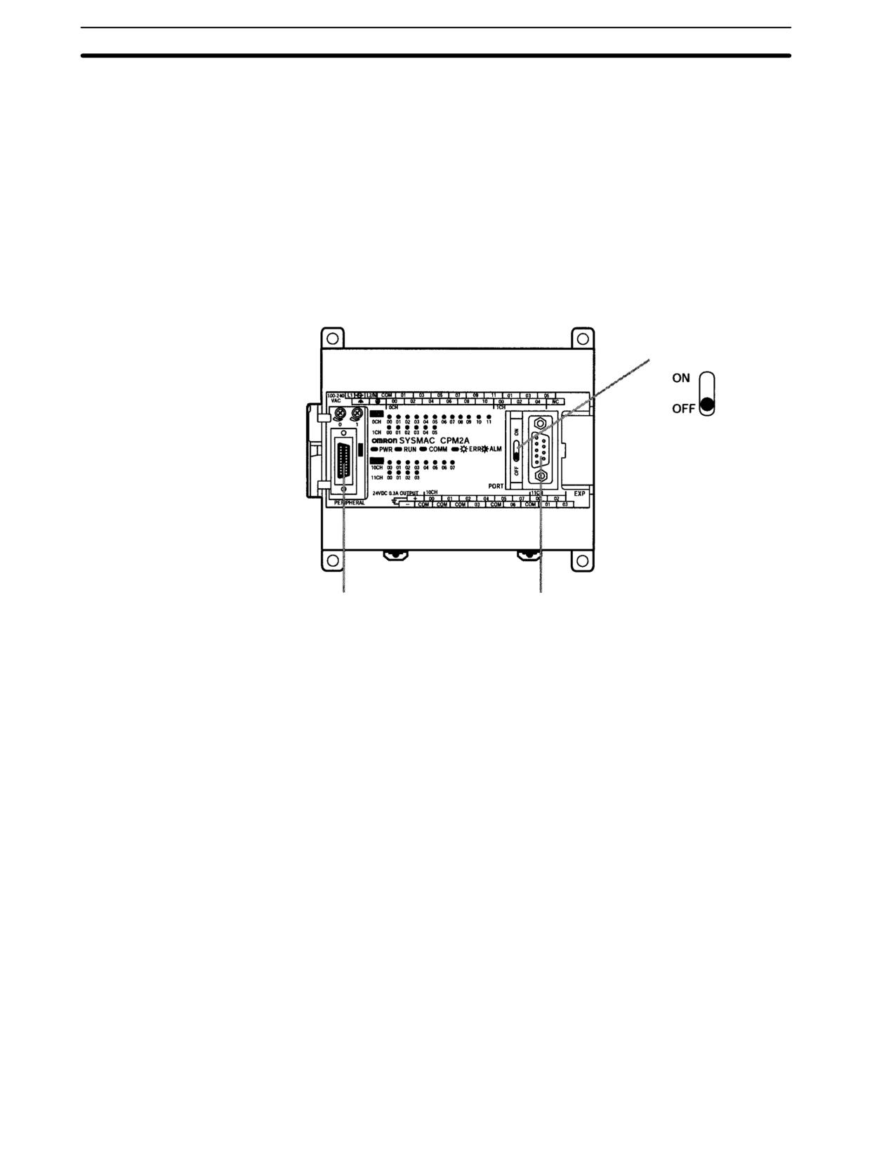
CPM2A/CPM2C Communications Functions
Section
4-3
Communications Switch
The CPM2A’s communications are controlled by the communications switch on
Setting
the front of the CPU Unit and the CPM2C’s communications are controlled by
the DIP switch on the front of the CPU Unit.
CPM2A Communications Switch Setting
When the communications switch is set to OFF, communications through the pe-
ripheral port and RS-232C port are governed by the settings in the PC Setup.
When the communications switch is set to ON, communications through the pe-
ripheral port and RS-232C port are governed by the standard Host Link settings
(1 start bit, 7 data bits, 2 stop bits, even parity, and 9,600 bps baud rate).
Note When a Programming Console is connected to the peripheral port, communica-
tions with the Programming Console are unaffected by either the communica-
tions switch or PC Setup.
Communications switch
Peripheral port
RS-232C port
An RS-232C Adapter is needed to perform Host Link communications from a
peripheral port.
239
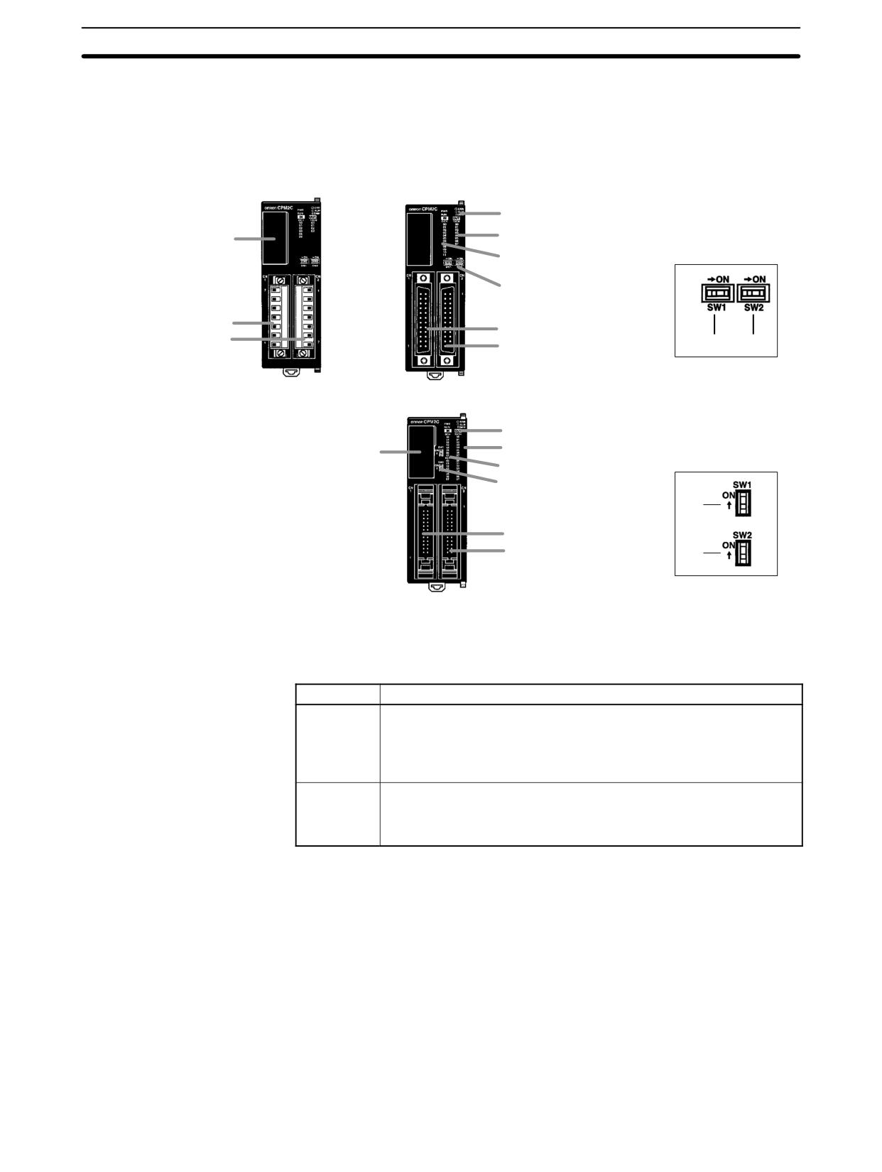
CPM2A/CPM2C Communications Functions
Section
4-3
CPM2C DIP Switch Settings
When SW2 is set to OFF, communications through the peripheral port are set to
Programming Console protocol, regardless of the setting of pin 1 or the settings
in the PC Setup.
Front View
CPU Unit with Relay Out-
CPU Unit with Transistor Outputs
puts via Terminal Block
via Fujitsu-compatible Connector
4. Status indicators
6. Output indicators
7. Communications port
DIP switch for Units
5. Input indicators
with 10/20 I/O points
8. Communications switch
9. Customize switch
2. Input terminals
2. Input connector
3. Output terminals
3. Output connector
(8)
(9)
CPU Unit with Transistor Outputs
via MIL Connector
4. Status indicators
6. Output indicators
DIP switch for Units
7. Communications port
with 32 I/O points
5. Input indicators
8. Communications switch
9. Customize switch
(8)
2. Input connector
3. Output connector
(9)
When SW 2 is set to ON, the status of SW 1 determines whether communica-
tions through the peripheral port and RS-232C port are governed by the settings
in the PC Setup or the standard settings (1 start bit, 7 data bits, 2 stop bits, even
parity, and 9,600 bps baud rate).
SW1
Communications settings
OFF
The communications settings for the peripheral port and RS-232C
port will be determined by the settings in the PC Setup (DM 6645 to
DM 6649, DM 6650 to DM 6654). If a Programming Console is
connected to the peripheral port, however, operation for that port will
be in the Programming Console mode.
ON
The communications settings for the peripheral port and RS-232C
port will be the standard settings. If a Programming Console is
connected to the peripheral port, however, operation for that port will
be in the Programming Console mode.
An RS-232C Adapter is needed to perform Host Link communications from a
peripheral port.
Note When performing host link communications via the peripheral port of a CPU Unit
with a manufacturing number of 3180O or earlier (i.e., manufactured on or
before April 31, 2000), set SW2 to ON. See above for details of the settings of
SW2. When using a CPU Unit with a manufacturing number of 3180O or earlier
(i.e., manufactured on or before April 31, 2000), do not change the setting of
SW2 with a Programming Console, the CPM2C-CIF01/11, or the
CQM1-CIF01/02 connected. If the setting of SW2 is changed in this state, com-
munications will be interrupted, and a communications error will be generated or
the Programming Console will enter a “no-response” state (i.e., pressing the
keys of the Programming Console will have no effect and the display will stay the
same).
240
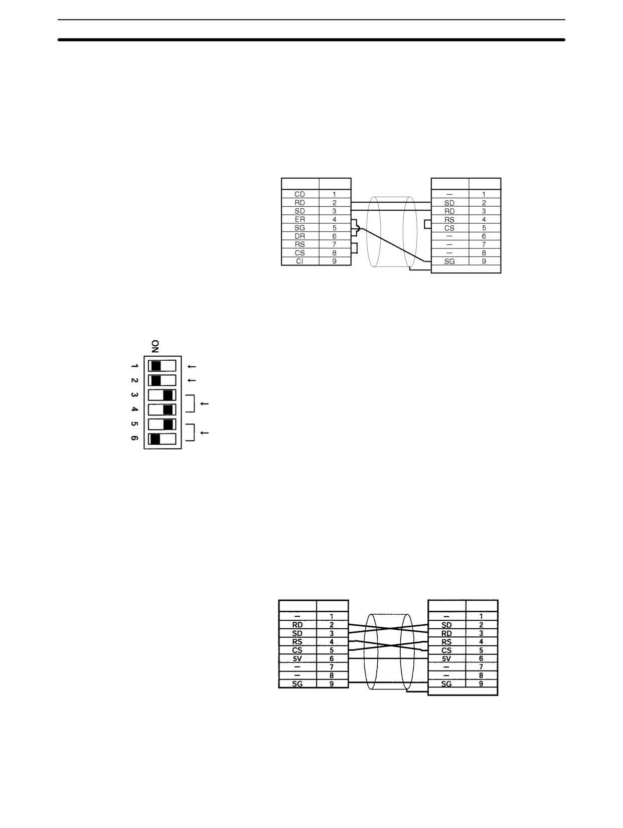
CPM2A/CPM2C Communications Functions
Section
4-3
Connecting the Cables
This section describes RS-232C connections.
One-to-one Connections
The RS-232C port on the Host Link computer and the RS-232C port on the
CPM2A/CPM2C or CPM1-CIF01 RS-232C Adapter are connected as shown in
the following diagram when there is no CTS control on the RS-232C port. With
the CPM2C, the CPM2C-CN111 and CS1W-CN118 connecting cables can be
used in place of the RS-232C Adapter.
IBM PC/AT or compatible
RS-232C port
Signal Pin No.
Signal
Pin No.
Hood
One-to-N Connections
Set the DIP switch on the NT-AL001 RS-232C/RS-422 Conversion Adapter.
Normally ON
ON when the Unit is at the end of the transmission path. OFF in all other cases.
Used as a 4-conductor method. (Both switches set to OFF)
According to RS-232C CTS control (5: OFF, 6: ON)
The RS-232C port with the NT-AL001 RS-232C/RS-422 Conversion Adapter
and the RS-232C port of the CPM2A/CPM2C or CPM1-CIF01 RS-232C Adapter
are connected as shown in the following diagram when there is no CTS control
on the RS-232C port. A power supply of 5 VDC is supplied to the
RS-232C/RS-422 Conversion Adapter. With the CPM2C, the CPM2C-CN111
and CS1W-CN118 connecting cables can be used in place of the RS-232C
Adapter.
NT-AL001 RS-232C/RS-422
Conversion Adapter
RS-232C port
Signal Pin No.
Signal Pin No.
Hood
Note Do not connect external devices other than the NT-AL001 Conversion Adapter
to the 5 VDC power supply of pin number 6 on the CPM2A/CPM2C’s RS-232C
port. Doing so may result in damage to the CPM2A/CPM2C or to the external
device.
241

CPM2A/CPM2C Communications Functions
Section
4-3
PC Setup
The PC Setup settings that are required depend on whether a peripheral port or
an RS-232C port is used.
Settings for RS-232C Port
Note If SW1 on the front panel of the CPU Unit is ON, the RS-232C port will operate
with the default settings regardless of the settings in DM 6645 to DM 6649.
Word
Bit
Function
Setting
DM 6645
00 to 03
Port settings
Match host
0: Standard (1 start bit, 7-bit data, 2 stop bits, even parity, 9,600 bps; Host
parameters
Link unit number: 0)
1: Settings in DM 6646
(Other settings will cause a non-fatal error, the default setting will be used,
and AR 1302 will turn ON.)
04 to 07
CTS control settings
0 or 1
0: Disable; 1: Set
08 to 11
Link words for 1:1 PC Link
Any
0: LR 00 to LR 15; Other: Not effective
12 to 15
Communications mode
0
0: Host Link (default setting); 1: RS-232C (no-protocol); 2: 1:1 PC Link Slave;
3: 1:1 PC Link Master; 4: 1:1 NT Link
(Other settings will cause a non-fatal error, the Host Link setting will be used,
and AR 1302 will turn ON.)
DM 6646
00 to 07
Baud rate:
Match host
parameters
00: 1,200 bps 01: 2,400 bps 02: 4,800 bps 03: 9,600 bps 04: 19,200 bps
08 to 15
Frame format
Start Length Stop Parity
00:
1
7
1
Even
01:
1
7
1
Odd
02:
1
7
1
None
03:
1
7
2
Even
04:
1
7
2
Odd
05:
1
7
2
None
06:
1
8
1
Even
07:
1
8
1
Odd
08:
1
8
1
None
09:
1
8
2
Even
10:
1
8
2
Odd
11:
1
8
2
None
(Other settings will cause a non-fatal error, the default settings (03) will be
used, and AR 1302 will turn ON.)
DM 6647
00 to 15
Transmission delay (Host Link)
0000 to 9999
0000 to 9999 (BCD): Set in units of 10 ms, e.g., setting of 0001 equals 10 ms
(Other settings will cause a non-fatal error, the default setting (0000) will be
used, and AR 1302 will turn ON.)
DM 6648
00 to 07
00 to 31 (BCD): Node number (Host Link)
00 to 31
(Other settings will cause a non-fatal error, the default setting (00) will be
used, and AR 1302 will turn ON.)
08 to 11
Start code enable (RS-232C)
Any
0: Disable; 1: Use start code in DM 6649.
12 to 15
End code enable (RS-232C)
Any
0: Disable (number of bytes received)
1: Use end code in DM 6649.
2: CR, LF
(Other settings will cause a non-fatal error, the disable setting will be used,
and AR 1302 will turn ON.)
242

CPM2A/CPM2C Communications Functions
Section
4-3
Word
Bit
Function
Setting
DM 6649
00 to 07
Start code (01 to FF)
Any
(No-protocol, effective when bits 8 to 11 of DM 6648 are set to 1.)
00 to 15
No. of bytes of data received
Any
(No-protocol, effective when bits 12 to 15 of DM 6648 are set to 0.)
00: 256 bytes
01 to FF: 1 to 255 bytes
End code (00 to FF)
(No-protocol, effective when bits 12 to 15 of DM 6648 are set to 1.)
Settings for Peripheral Port
Word
Bit
Function
Setting
DM 6650
00 to 03
Port settings
Match host
0: Standard (1 start bit, 7-bit data, 2 stop bits, even parity, 9,600 bps; Host
parameters
Link unit number: 0)
1: Settings in DM 6651
(Other settings will cause a non-fatal error, the default setting (0) will be
used, and AR 1302 will turn ON.)
04 to 11
Not used
0
12 to 15
Communications mode
0
0: Host Link or peripheral bus; 1: No-protocol
(Other settings will cause a non-fatal error, the Host Link setting (0) will be
used, and AR 1302 will turn ON.)
DM 6651
00 to 07
Baud rate
Match host
parameters
00: 1,200 bps, 01: 2,400 bps, 02: 4,800 bps, 03: 9,600 bps, 04: 19,200 bps
08 to 15
Frame format
Start Length Stop Parity
00:
1
7
1
Even
01:
1
7
1
Odd
02:
1
7
1
None
03:
1
7
2
Even
04:
1
7
2
Odd
05:
1
7
2
None
06:
1
8
1
Even
07:
1
8
1
Odd
08:
1
8
1
None
09:
1
8
2
Even
10:
1
8
2
Odd
11:
1
8
2
None
(Other settings will cause a non-fatal error, the default settings (03) will be
used, and AR 1302 will turn ON.)
DM 6652
00 to 15
Transmission delay (Host Link)
0000 to 9999
0000 to 9999 (BCD): Set in units of 10 ms.
(Other settings will cause a non-fatal error, the default setting (0000) will be
used, and AR 1302 will turn ON.)
Note
1. If SW1 on the front panel of the CPU Unit is ON, the peripheral port will oper-
ate with the default settings regardless of the settings in DM 6645 to
DM 6649.
2. When connecting a computer running Support Software via the peripheral
bus, turn OFF SW1 on the front panel of the CPU Unit and set DM 6650 to
0001 (Host Link). The CPU Unit will automatically switch to peripheral bus
communications for the serial communications port.
243

CPM2A/CPM2C Communications Functions
Section
4-3
Word
Bit
Function
Setting
DM 6653
00 to 07
Node number (Host Link)
00 to 31
00 to 31 (BCD)
(Other settings will cause a non-fatal error, the default setting (03) will be
used, and AR 1302 will turn ON.)
08 to 11
Start code enable (Peripheral port)
Any
0: Disable
1: Use start code in DM 6654.
12 to 15
End code enable (Peripheral port)
Any
0: Disable (number of bytes received)
1: Use end code in DM 6654.
2: CR, LF
(Other settings will cause a non-fatal error, the disable setting (0) will be
used, and AR 1302 will turn ON.)
DM 6654
00 to 07
Start code
Any
(Peripheral port, effective when bits 08 to 11 of DM 6653 are set to 1.)
01 to FF (Hex)
08 to 15
No. of bytes of data received
Any
(Peripheral port, effective when bits 12 to 15 of DM 6653 are set to 0.)
00: 256 bytes
01 to FF: 1 to 255 bytes
End code (00 to FF)
(Peripheral port, effective when bits 12 to 15 of DM 6653 are set to 1.)
244
CPM2A/CPM2C Communications Functions
Section
4-3
Issuing Commands from
This example shows a BASIC program that reads the status of the CPM2A/
a Host Computer
CPM2C’s inputs in IR 000. For more details see 4-5 Host Link Commands.
An FCS (frame check sequence) check isn’t performed on the received re-
sponse data in this program.
Be sure that the host computer’s RS-232C port is configured correctly before
executing the program.
1000 ’ ----------------------------------------------------------------------
1010 ’ CPM2A/CPM2C Sample Program for BASIC
1020 ’
1050 ’ ----------------------------------------------------------------------
1060 ’ ---Set value RS-232C SPEED:9600BPS,PARITY:EVEN,DATA:7,STOP:2---
1070 OPEN ”COM:E73” AS
#1
1080 *REPEAT
1090
---Transmission data input-----------------------------------------------
1100 INPUT
” send data
: ”,send$
1110 ’ ---FCS Calculation-----------------------------------------------
1120 FCS=0
1130 FOR IFCS = 1 TO LEN ( send$ )
1140
FCS = FCS XOR ASC( MID$ ( SEND$ , IFCS , 1 ) )
1150 NEXT
1160 FCS$ = RIGHT$ ( ”0” + HEX$ ( FCS ) , 2 )
1170 ’ ---Communications execute-----------------------------------------------
1180 ZZZ$ = SEND$ + SCS$ + ”*” + CHR$(13)
1190 PRINT
#1 , ZZZ$ ;
1200 ’ ---Response check-----------------------------------------------
1210 RECCNT = 0 : TMP$ - ””
1220 *DRECLOOP
1230 IF LOC ( 1 ) < > 0 THEN *DREC1
1240 RECCNT = RECCNT + 1
1250 IF RECCNT = 5000 THEN *DRECERR ELSE *DRECLOOP
1260 *DREC1
1270 TMP$ = TMP$ + INPUT$ ( LOC (1 ) , #1 )
1280 IF RIGHT$ ( TMP$ , 1 ) = CHR$ (13) THEN *DRECEND ELSE RECCNT = 0 : GOTO *
DRECLOOP
1290 *DRECERR
1300 TMP$ = ” No response !! ” + CHR$ ( 13 )
1310 *DRECEND
1320 PRINT ” receive data : ” ; RECV$
1340 ’ ---Go to transmission data input----------------------------------------
1350 GOTO *REPEAT
1360 ’ ---Processing complete-----------------------------------------------
1370 CLOSE
#1
1380 END
245
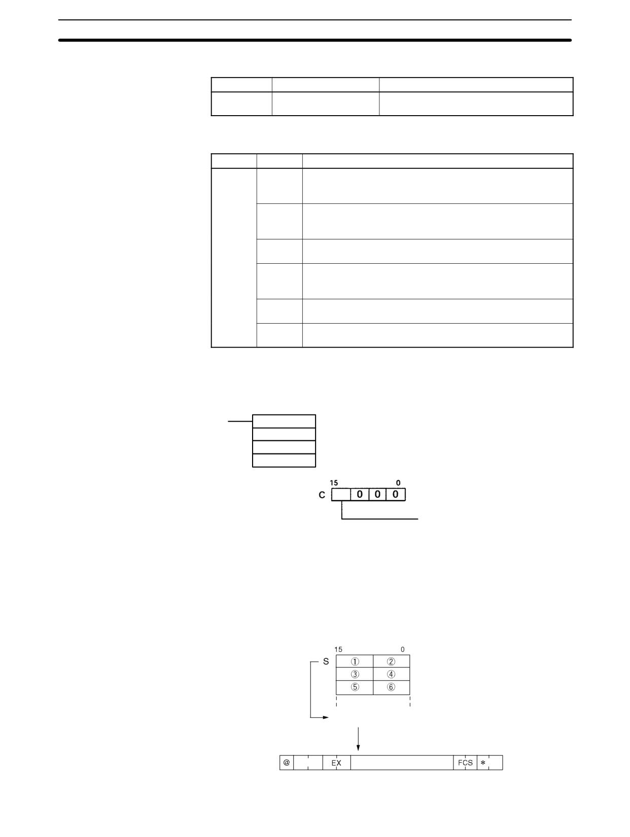
CPM2A/CPM2C Communications Functions
Section
4-3
The unsolicited Host Link communications are executed using TXD(48).
Ladder Program
(Mnemonics)
Mnemonic
Control
Contents
(@)TXD(48)
Communications port
Reads data from I/O memory and transmits
output
it in the specified frame format.
Host Link communications are controlled with the following AR area flags.
Word
Bit(s)
Contents
AR 08
00 to 03
RS-232C Port Error Code
0: Normal completion
1: Parity error
2: Frame error
3: Overrun error
04
RS-232C Communications Error Flag
ON: RS-232C port communications error occurred
OFF: Normal
05
RS-232C Transmit Ready Flag
ON: The PC is ready to transmit data.
08 to 11
Peripheral Port Error Code
0: Normal completion
1: Parity error
2: Frame error
3: Overrun error
12
Peripheral Port Communications Error Flag
ON: Peripheral port communications error occurred.
13
Peripheral Port Transmit Ready Flag
ON: The PC is ready to transmit data.
Unsolicited Communications
A data transmission to the host computer is initiated by the PC.
(@)TXD(48)
S
S: Leading address of data to be transmitted
C
C: Control data
N N: Number of bytes to be transmitted (BCD: 0001 to 0061)
Communications port
0: RS-232 port; 1: Peripheral port
When Host Link communications are being used, TXD(48) converts the N-bytes
of data starting at S to ASCII, adds the Host Link header, FCS, and terminator,
and transmits this data as a Host Link frame.
The transmitted Host Link frame will be as shown in the following diagram.
Converted to ASCII.
N bytes
Node No.
Data (ASCII)
↵
246
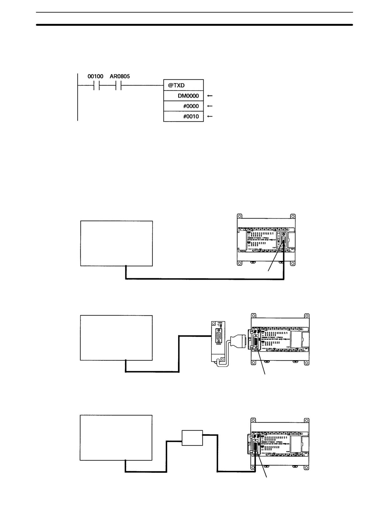
CPM2A/CPM2C Communications Functions
Section
4-3
In the following program example TXD(48) is used to transmit data from an
RS-232C port to a host computer. If AR 0805 (the RS-232C Transmit Ready
Flag) is ON when IR 00100 turns ON, the ten bytes of data (DM 0100 to
DM 0104) will be transmitted to the host computer, leftmost bytes first.
(48)
Leading address of data to be transmitted
RS-232C port specification
10 bytes
4-3-2
No-protocol Communications
Overview
When no-protocol communications are used, data can be exchanged with serial
devices such as bar code readers and serial printers using TXD(48) and
RXD(47). No-protocol communications can be used with either an RS-232C
port or peripheral port.
CPM2A Connections
CPM2A CPU Unit
RS-232C devices
Bar code reader
Serial printer
Other
RS-232C port
CPM2A CPU Unit
CPM1-CIF01 RS-232C Adapter
(CTS control cannot be used.)
RS-232C devices
Bar code reader
Serial printer
Other
Peripheral port
CPM2A CPU Unit
CQM1-CIF01/02 RS-232C Adapter
RS-232C devices
(CTS control cannot be used.)
Bar code reader
Serial printer
Other
Peripheral port
247
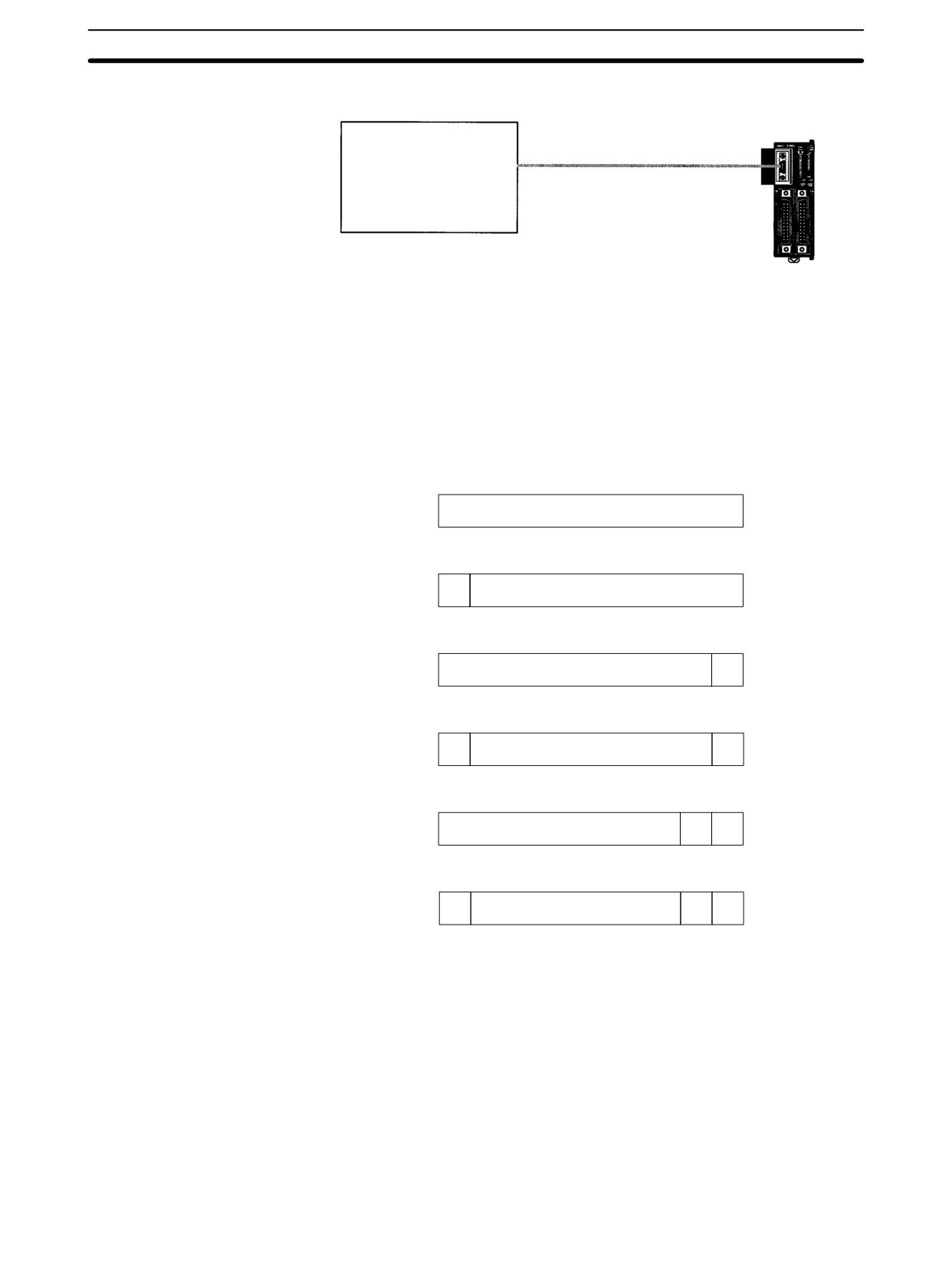
CPM2A/CPM2C Communications Functions
Section
4-3
CPM2C Connections
CPM2C CPU Unit
RS-232C devices
Bar code reader
Serial printer
Other
Note A CPM1-CIF01 RS-232C Adapter can also be used for no-protocol communica-
tions through the peripheral port, or for a CPM2C, a CPM2C-CIF01 Peripheral/
RS-232C Adapter Unit can be used to connect to external devices. Refer to the
CPM2C Operation Manual for details.
Transmission Data Configuration
When no-protocol communications are used, TXD(48) is used to send data and
RXD(47) to receive data. The maximum amount of data that can be either sent or
received is 259 bytes, including the start and end codes.
No Start or End Code:
Data (Specified No. of bytes)
Only a Start Code:
ST
Data (Specified No. of bytes)
Only an End Code:
Data (256 bytes max.)
ED
Both a Start and End Code:
ST
Data (256 bytes max.)
ED
End Code of CR, LF:
Data (256 bytes max.)
CR
LF
Start Code 00-FF/End Code CR,LF:
ST
Data (256 bytes max.)
CR
LF
Note
1. The start and end codes are set in DM 6648 to DM 6649 (RS-232C) or
DM 6653 to DM 6654 (peripheral port) in the PC Setup.
2. When there are several start or end codes in the transmission, the first of
each will be effective.
3. When the end code is accidentally duplicated in the transmission data and
the transmission is stopped part way through, use CR and LF as the end
code.
4. The start and end codes themselves are not transmitted and received.
Transmission Flags
When sending data from the CPM2A/CPM2C, check that the Transmission En-
able Flag is ON for executing TXD(48). The Transmission Enable Flag will turn
248
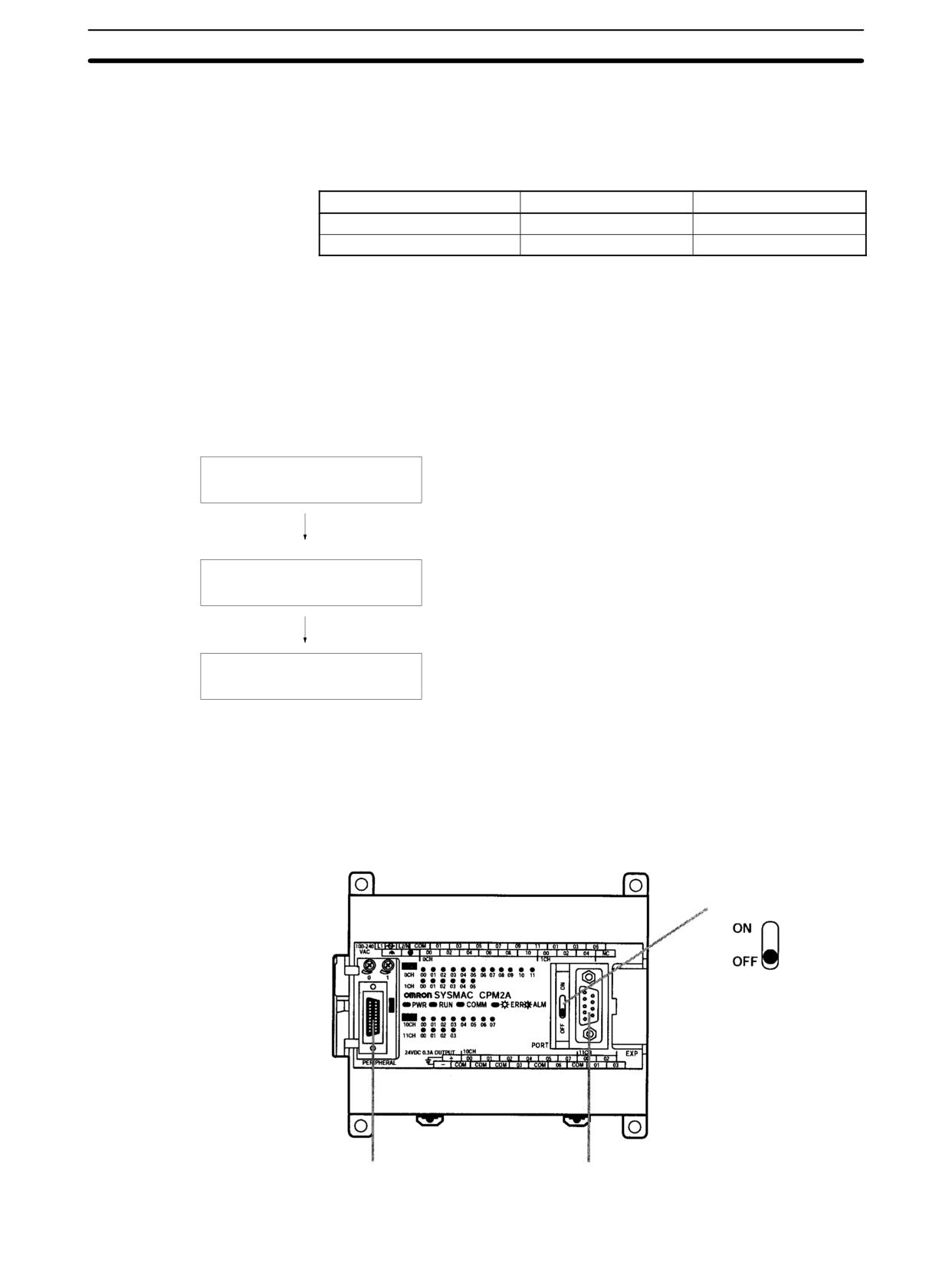
CPM2A/CPM2C Communications Functions
Section
4-3
OFF while the data is being transmitted and will turn ON again when transmis-
sion is complete.
After the CPM2A/CPM2C has received data, the Receive Enable Flag turns ON.
When RXD(47) is executed, the data received will be written to the specified
words and the Reception Complete Flag will turn OFF.
Flag
Peripheral port
RS-232C port
Transmit Ready Flag
AR 0813
AR 0805
Reception Completed Flag
AR 0814
AR 0806
Note The CPM2A/CPM2C starts and completes data reception at the following
points:
Reception Start:
Start code disabled:
Continually available for reception
Start code enabled:
After start code is received
Reception Complete:
When either the end code, the specified no. of bytes, or 256 bytes are received.
Application Procedure
Setting the Communications switch
Set the CPM2A CPU Unit’s communications switch or
the CPM2C CPU Unit’s DIP switch.
Connecting the cables
Make the RS-232C connection with the serial device.
Ladder program
Communications Switch
The CPM2A’s communications are controlled by the communications switch on
Setting
the front of the CPU Unit and the CPM2C’s communications are controlled by
the DIP switch on the front of the CPU Unit.
CPM2A Communications Switch Setting
Turn OFF the Communications switch when using no-protocol communications.
No-protocol communications will not be possible if the communications switch is
ON.
Communications switch
Peripheral port
RS-232C port
249
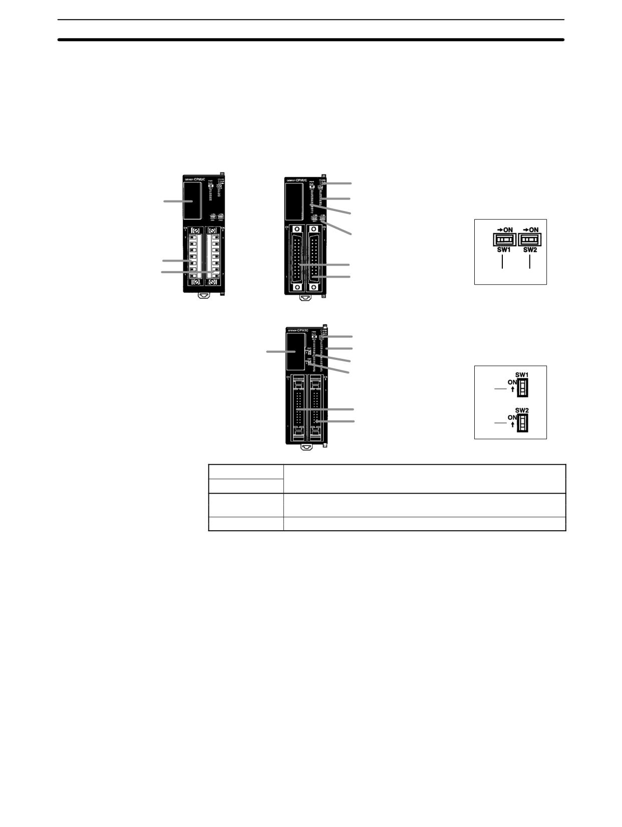
CPM2A/CPM2C Communications Functions
Section
4-3
Note An RS-232C adapter is required for no-protocol communications on the periph-
eral port.
CPM2C DIP Switch Settings
Turn OFF pin 1 of the DIP switch when using no-protocol communications so
that communications through the RS-232C port are governed by the settings in
the PC Setup (DM 6645 to DM 6649).
Front View
CPU Unit with Relay Out-
CPU Unit with Transistor Outputs
puts via Terminal Block
via Fujitsu-compatible Connector
4. Status indicators
6. Output indicators
7. Communications port
DIP switch for Units
5. Input indicators
with 10/20 I/O points
8. Communications switch
9. Customize switch
2. Input terminals
2. Input connector
3. Output terminals
3. Output connector
(8)
(9)
CPU Unit with Transistor Outputs
via MIL Connector
4. Status indicators
7. Communications port
6. Output indicators
DIP switch for Units
with 32 I/O points
5. Input indicators
8. Communications switch
9. Customize switch
(8)
2. Input connector
3. Output connector
(9)
Pin settings
RS-232C port communications
Pin 1
OFF
Governed by the PC Setup
(DM 6645 to DM 6649)
ON
Governed by standard settings
Note An RS-232C Adapter is needed to perform no-protocol communications through
the peripheral port.
Connecting the Cables
This section describes RS-232C connections.
The RS-232C port on the serial device and the RS-232C port of the CPM2A/
CPM2C or CPM1-CIF01 RS-232C Adapter are connected as shown in the fol-
250
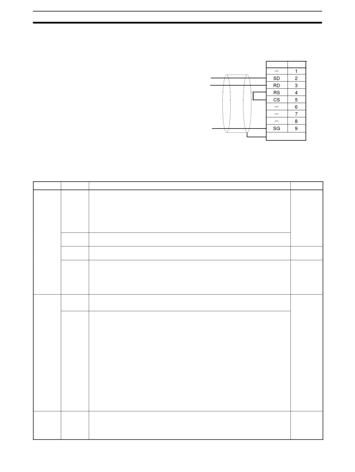
CPM2A/CPM2C Communications Functions
Section
4-3
lowing diagram. With the CPM2C, the CPM2C-CN111 and CS1W-CN118 con-
necting cables can be used in place of the RS-232C Adapter.
RS-232C port
Signal Pin No.
Serial device RD (receive data)
Serial device SD (send data)
Serial device SG (signal ground)
Hood
PC Setup
The PC Setup settings that are required depend on whether a peripheral port or
an RS-232C port is used.
Settings for RS-232C Port
Word
Bit
Function
Setting
DM 6645
00 to 03
Port settings
As required
0: Standard (1 start bit, 7-bit data, 2 stop bits, even parity, 9,600 bps; Host Link
unit number: 0)
1: Settings in DM 6646
(Other settings will cause a non-fatal error, the default setting will be used, and AR
1302 will turn ON.)
04 to07
CTS control settings
0: Disable; 1: Set
08 to 11
Link words for 1:1 PC Link
Any
0: LR 00 to LR 15; Other: Not effective
12 to 15
Communications mode
1
0: Host Link; 1: No-protocol; 2: 1:1 PC Link Slave; 3: 1:1 PC Link Master; 4: 1:1 NT
Link
(Other settings will cause a non-fatal error, the Host Link setting will be used, and
AR 1302 will turn ON.)
DM 6646
00 to 07
Baud rate
As required
00: 1,200 bps; 01: 2,400 bps; 02: 4,800 bps; 3: 9,600 bps; 04: 19,200 bps
08 to 15
Frame format
Start Length Stop Parity
00:
1
7
1
Even
01:
1
7
1
Odd
02:
1
7
1
None
03:
1
7
2
Even
04:
1
7
2
Odd
05:
1
7
2
None
06:
1
8
1
Even
07:
1
8
1
Odd
08:
1
8
1
None
09:
1
8
2
Even
10:
1
8
2
Odd
11:
1
8
2
None
(Other settings will cause a non-fatal error, the default settings (03) will be used,
and AR 1302 will turn ON.)
DM 6647
00 to 15
Transmission delay (Host Link)
0000 to
0000 to 9999 (BCD): Set in units of 10 ms, e.g., setting of 0001 equals 10 ms
9999
(Other settings will cause a non-fatal error, the default setting (0000) will be used,
and AR 1302 will turn ON.)
251

CPM2A/CPM2C Communications Functions
Section
4-3
Word
Bit
Function
Setting
DM 6648
00 to 07
00 to 31 (BCD): Node number (Host Link)
As required
(Other settings will cause a non-fatal error, the default setting (00) will be used, and
AR 1302 will turn ON.)
08 to 11
Start code enable (RS-232C)
0 or 1
0: Disable; 1: Use start code in DM 6649.
12 to 15
End code enable (RS-232C)
0 to 2
0: Disable (number of bytes received)
1: Use end code in DM 6649.
2: CR, LF
(Other settings will cause a non-fatal error, the default setting (0) will be used, and
AR 1302 will turn ON.)
DM 6649
00 to 07
Start code (00 to FF)
00 to FF
(No-protocol, effective when bits 8 to 11 of DM 6648 are set to 1.)
08 to 15
No. of bytes of data received
00 to FF
(No-protocol, effective when bits 12 to 15 of DM 6648 are set to 0.)
00: 256 bytes
01 to FF: 1 to 255 bytes
End code (00 to FF)
00 to FF
(No-protocol, effective when bits 12 to 15 of DM 6648 are set to 1.)
Note If SW1 on the front panel of the CPU Unit is ON, the RS-232C port will operate
with the default settings regardless of the settings in DM 6645 to DM 6649.
Settings for Peripheral Port
Word
Bit
Function
Setting
DM 6650
00 to 03
Port settings
As required
0: Standard (1 start bit, 7-bit data, 2 stop bits, even parity, 9,600 bps; Host Link
unit number: 0)
1: Settings in DM 6651
(Other settings will cause a non-fatal error, the default setting (0) will be used, and
AR 1302 will turn ON.)
04 to 11
Not used
0
12 to 15
Communications mode
1
0: Host Link or peripheral bus; 1: No-protocol
(Other settings will cause a non-fatal error, the Host Link setting will be used, and
AR 1302 will turn ON.)
DM 6651
00 to 07
Baud rate
As required
00: 1,200 bps; 01: 2,400 bps; 02: 4,800 bps; 03: 9,600 bps; 04: 19,200 bps
08 to 15
Frame format
Start Length Stop Parity
00:
1
7
1
Even
01:
1
7
1
Odd
02:
1
7
1
None
03:
1
7
2
Even
04:
1
7
2
Odd
05:
1
7
2
None
06:
1
8
1
Even
07:
1
8
1
Odd
08:
1
8
1
None
09:
1
8
2
Even
10:
1
8
2
Odd
11:
1
8
2
None
(Other settings will cause a non-fatal error, the default settings (03) will be used,
and AR 1302 will turn ON.)
DM 6652
00 to 15
Transmission delay (Host Link)
0000 to
0000 to 9999 (BCD): Set in units of 10 ms.
9999
(Other settings will cause a non-fatal error, the default setting (0000) will be used,
and AR 1302 will turn ON.)
252
CPM2A/CPM2C Communications Functions
Section
4-3
Word
Bit
Function
Setting
DM 6653
00 to 07
00 to 31 (BCD): Node number (Host Link)
As required
(Other settings will cause a non-fatal error, the default setting (00) will be used, and
AR 1302 will turn ON.)
08 to 11
Start code enable (Peripheral port)
0 or 1
0: Disable
1: Use start code in DM 6654.
12 to 15
End code enable (Peripheral port)
0 to 2
0: Disable (number of bytes received)
1: Use end code in DM 6654.
2: CR. LF
(Other settings will cause a non-fatal error, the default setting (0) will be used, and
AR 1302 will turn ON.)
DM 6654
00 to 07
Start code (00 to FF)
00 to FF
(Peripheral port, effective when bits 8 to 11 of DM 6653 are set to 1.)
08 to 15
No. of bytes of data received
00 to FF
(Peripheral port, effective when bits 12 to 15 of DM 6653 are set to 0.)
00: 256 bytes
01 to FF: 1 to 255 bytes
End code (00 to FF)
00 to FF
(Peripheral port, effective when bits 12 to 15 of DM 6653 are set to 1)
Note
1. If SW1 on the front panel of the CPU Unit is ON, the peripheral port will oper-
ate with the default settings regardless of the settings in DM 6645 to
DM 6649.
2. When connecting a computer running Support Software via the peripheral
bus, turn OFF SW1 on the front panel of the CPU Unit and set DM 6650 to
0001 (Host Link). The CPU Unit will automatically switch to peripheral bus
communications for the serial communications port.
Program
The following instructions are used in no-protocol communications.
Mnemonic
Control
Contents
(@)TXD(48)
Communications
Reads data from I/O memory and transmits it in
port output
the specified frame format (the start and end
codes can be enabled/disabled).
(@)RXD(47)
Communications
Receives data in the specified frame format (the
port input
start and end codes can be enabled/disabled)
and stores only the data in I/O memory.
253
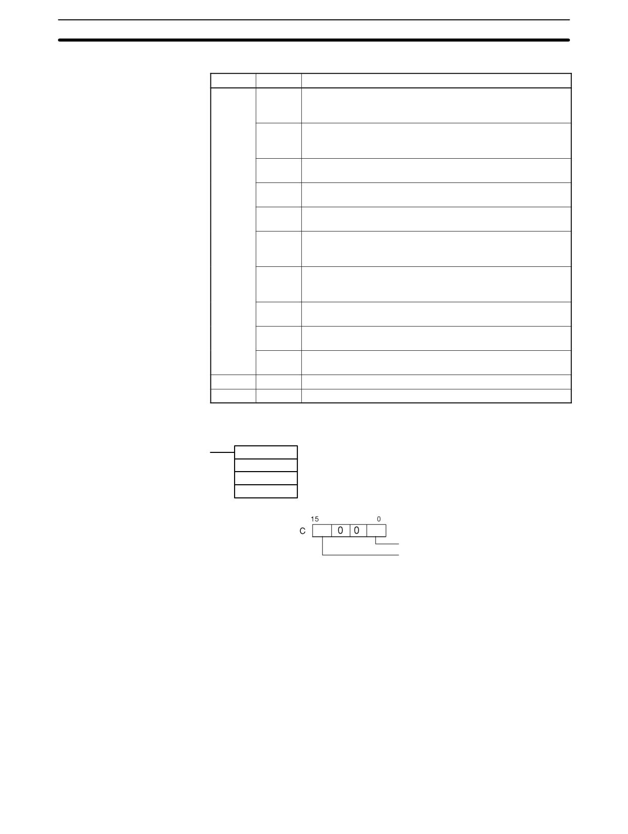
CPM2A/CPM2C Communications Functions
Section
4-3
No-protocol communications are controlled with the following AR area flags.
Word
Bit(s)
Contents
AR 08
00 to 03
RS-232C Port Error Code
0: Normal completion;
1: Parity error;
2: Frame error;
3: Overrun error
04
RS-232C Communications Error Flag
ON: RS-232C port communications error occurred.
OFF: Normal
05
RS-232C Transmit Ready Flag
ON: The PC is ready to transmit data.
06
RS-232C Reception Completed Flag
ON: The PC has completed reading data.
07
RS-232C Reception Overflow Flag
ON: A reception overflow has occurred.
08 to 11
Peripheral Port Error Code
0: Normal completion;
1: Parity error;
2: Frame error;
3: Overrun error
12
Peripheral Port Communications Error Flag
ON: A peripheral port communications error occurred.
OFF: Normal
13
Peripheral Port Transmit Ready Flag
ON: The PC is ready to transmit data.
14
Peripheral Port Reception Completed Flag
ON: The PC has completed reading data.
15
Peripheral Port Reception Overflow Flag
ON: A reception overflow has occurred.
AR 09
00 to 15
RS-232C Port Reception Counter (4 digits BCD)
AR 10
00 to 15
Peripheral Port Reception Counter (4 digits BCD)
No-protocol Data Transmission
TXD(48) is used to transmit data to RS-232C devices.
(@)TXD(48)
S
S: Leading address of data to be transmitted
C
C: Control data
N N: Number of bytes to be transmitted (BCD: 0001 to 0256)
Storage order
0: Leftmost bytes first 1: Rightmost bytes first
Communications port
0: RS-232C port 1: Peripheral port
When no-protocol communications are being used, TXD(48) transmits N bytes
of data beginning at S.
254
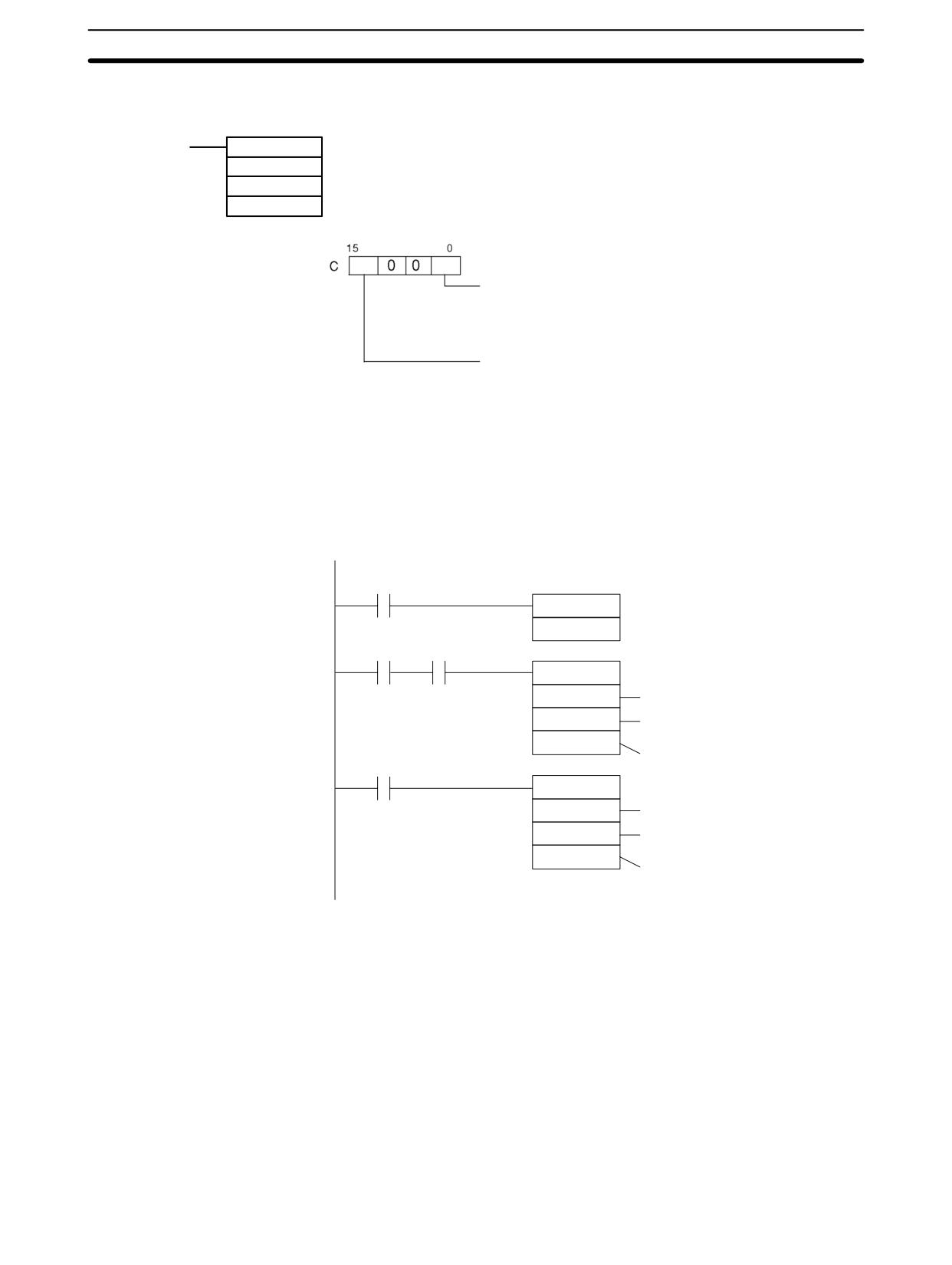
CPM2A/CPM2C Communications Functions
Section
4-3
No-protocol Data Reception
RXD(47) is used to receive data from RS-232C devices.
(@)RXD(47)
S
D: Leading address for storing reception data
C
C: Control data
N
N: Number of bytes to receive (BCD: 0001 to 0256)
Storage order
0: Leftmost bytes first 1: Rightmost bytes first
Communications port
0: RS-232C port 1: Peripheral port
The following program example is for no-protocol communications conducted
through a RS-232C port using TXD(48) and RXD(47) instructions.
If AR 0805 (the RS-232C Transmit Ready Flag) is ON when 00100 turns ON,
then data from DM 0100 to DM 0104 is transmitted from leftmost bytes to right-
most bytes. When AR 0806 (the Reception Completed Flag) turns ON, 256 by-
tes of received data are read and written to DM 0200 from leftmost bytes to right-
most bytes.
00100
DIFU(13)
No-protocol communications start
00101
00101
AR 0805
@TXD(48)
DM 0100
First word holding send data.
#0000
Use the RS-232C port; transmit
data from leftmost bytes to right-
#0010
most bytes.
AR 0806
Transmit 10 bytes.
RXD(47)
DM 0200
First word to store received data.
Use the RS-232C port; store trans-
#0000
mitted data from leftmost bytes to
rightmost bytes.
#0256
Receive 256 bytes.
255
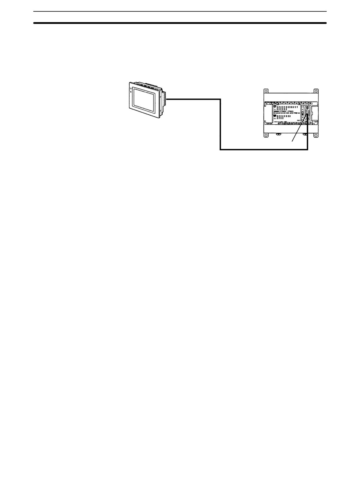
CPM2A/CPM2C Communications Functions
Section
4-3
4-3-3
One-to-one NT Link Communications
The NT Link allows a CPM2A/CPM2C PC to be connected directly to an OM-
RON Programmable Terminal. There is no need for a communications program
on the PC. The NT Link can be used with an RS-232C port.
CPM2A Connection
CPM2A CPU Unit
RS-232C cable
OMRON Programmable
Terminal
RS-232C port
256
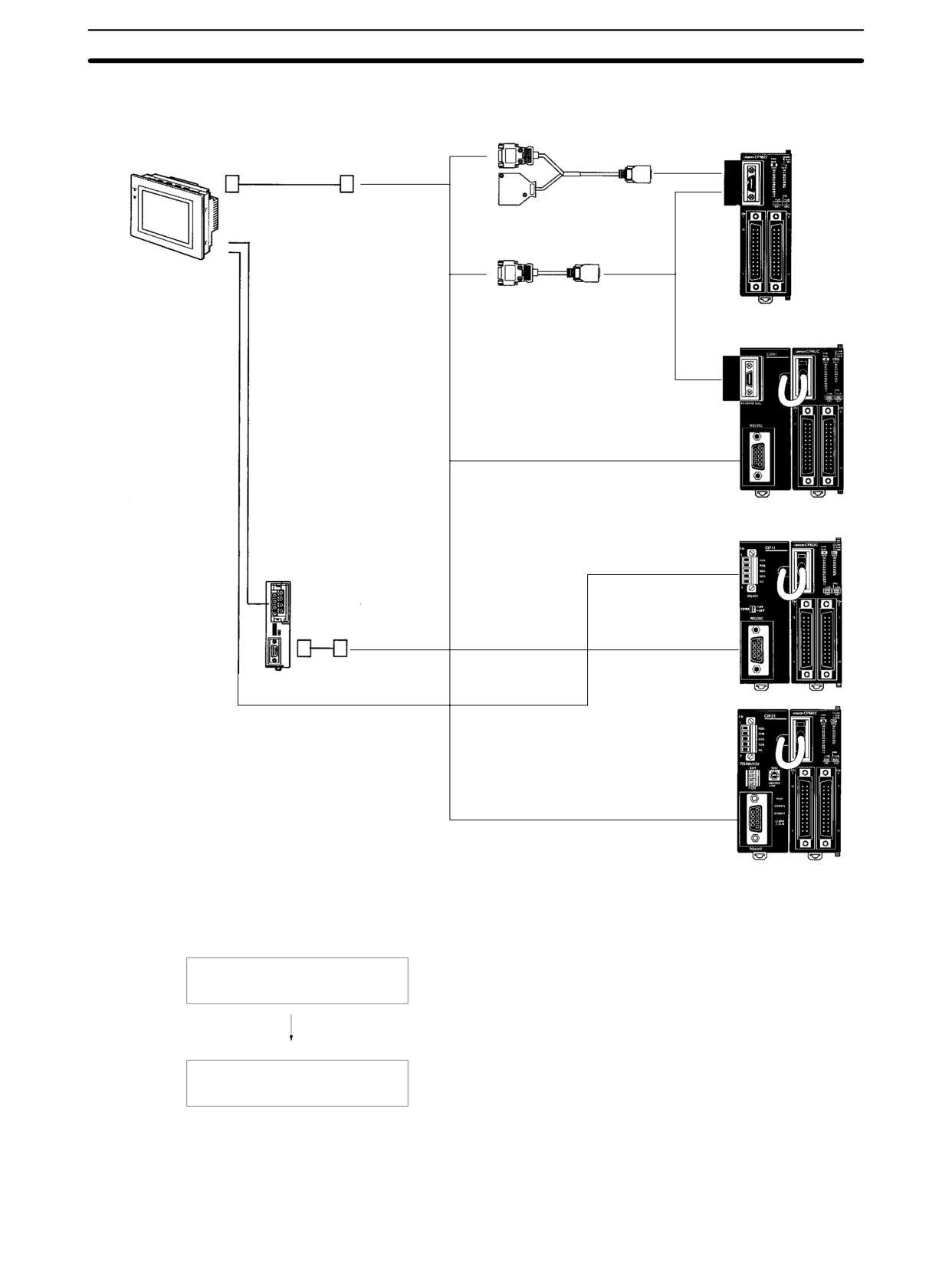
CPM2A/CPM2C Communications Functions
Section
4-3
CPM2C/CPM2C-S 1:1 NT Link Connection
RS-232C port
Connecting Cable
(D-sub 9-pin)
CPM2C CPU Unit
XW2Z-200T (2 m)
RS-232C
port
XW2Z-500T (5 m)
RS-232C connection
CPM2C-CN111 (0.15 m)
OMRON
Programmable
Terminal
CS1W-CN118 (0.1 m)
RS-232C ← peripheral port
RS-422 connection
RS-232C port
CPM2C-CIF01
RS-422 ← peripheral port
NT-AL001
RS-232C Adapter
RS-232C port
CPM2C-CIF11
XW2Z-070T-1 (0.7 m)
XW2Z-200T-1 (2 m)
RS-232C port
CPM2C-CIF21
Note The Programmable Terminal cannot be connected using a peripheral port con-
nection when communicating via a 1:1 NT Link.
Application Procedure
Use the settings in the PC Setup (DM6645 to DM 6649) for
Setting communications.
RS-232C communications.
(Turn OFF the Communications switch on the CPM2A’s CPU
Unit or pin 1 of the DIP Switch on the CPM2C’s CPU Unit.)
Connecting the cables
Connect to a Programmable Terminal.
Communications Switch
The CPM2A’s communications are controlled by the communications switch on
Setting
the front of the CPU Unit and the CPM2C’s communications are controlled by
the DIP switch on the front of the CPU Unit.
257
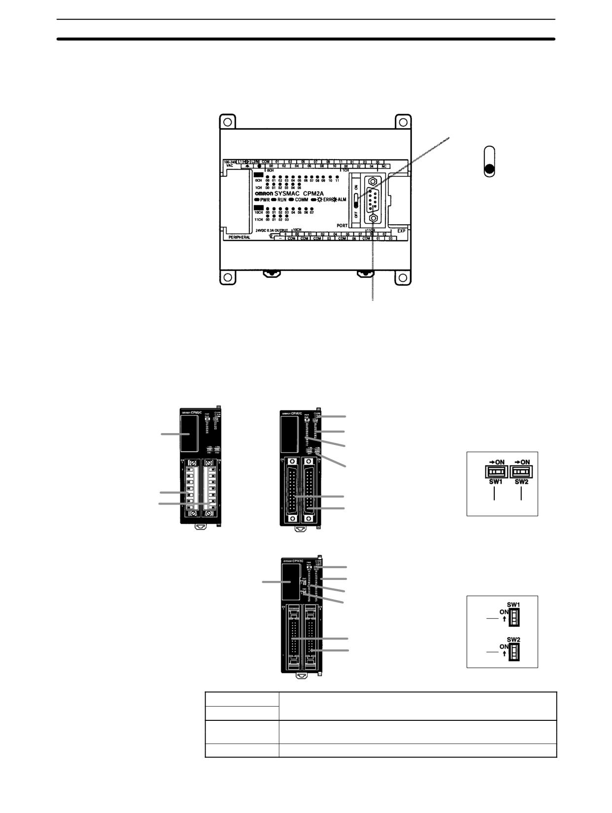
CPM2A/CPM2C Communications Functions
Section
4-3
CPM2A Communications Switch Setting
Turn OFF the communications switch when using 1:1 NT Link communications.
One-to-one NT Link communications will not be possible if the communications
switch is ON.
Communications switch
ON
OFF
RS-232C port
CPM2C DIP Switch Settings
Turn OFF pin 1 of the DIP switch when using 1:1 NT Link communications so that
communications through the RS-232C port are governed by the settings in the
PC Setup (DM 6645 to DM 6649).
Front View
CPU Unit with Relay Out-
CPU Unit with Transistor Outputs
puts via Terminal Block
via Fujitsu-compatible Connector
4. Status indicators
6. Output indicators
7. Communications port
DIP switch for Units
5. Input indicators
with 10/20 I/O points
8. Communications switch
9. Customize switch
2. Input terminals
2. Input connector
3. Output terminals
3. Output connector
(8)
(9)
CPU Unit with Transistor Outputs
via MIL Connector
4. Status indicators
6. Output indicators
DIP switch for Units
7. Communications port
with 32 I/O points
5. Input indicators
8. Communications switch
9. Customize switch
(8)
2. Input connector
3. Output connector
(9)
Pin settings
RS-232C port communications
Pin 1
OFF
Governed by the PC Setup
(DM 6645 to DM 6649)
ON
Governed by standard settings
258