FANUC I/O Unit-MODEL A. CONNECTION AND MAINTENANCE MANUAL (B-61813E/04) - page 7
B-61813E/04
CONNECTION
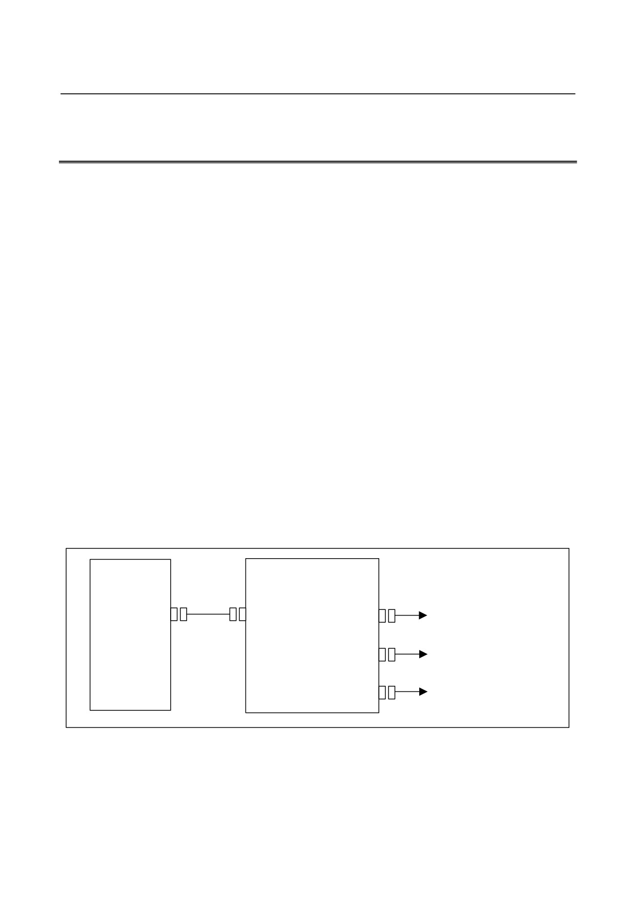
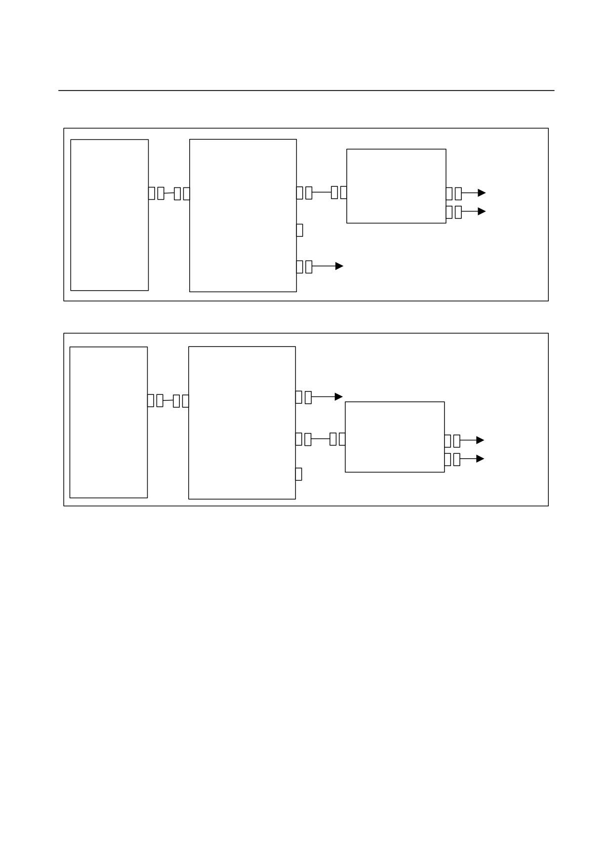
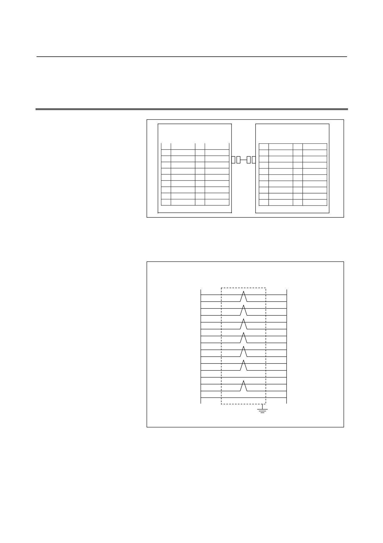
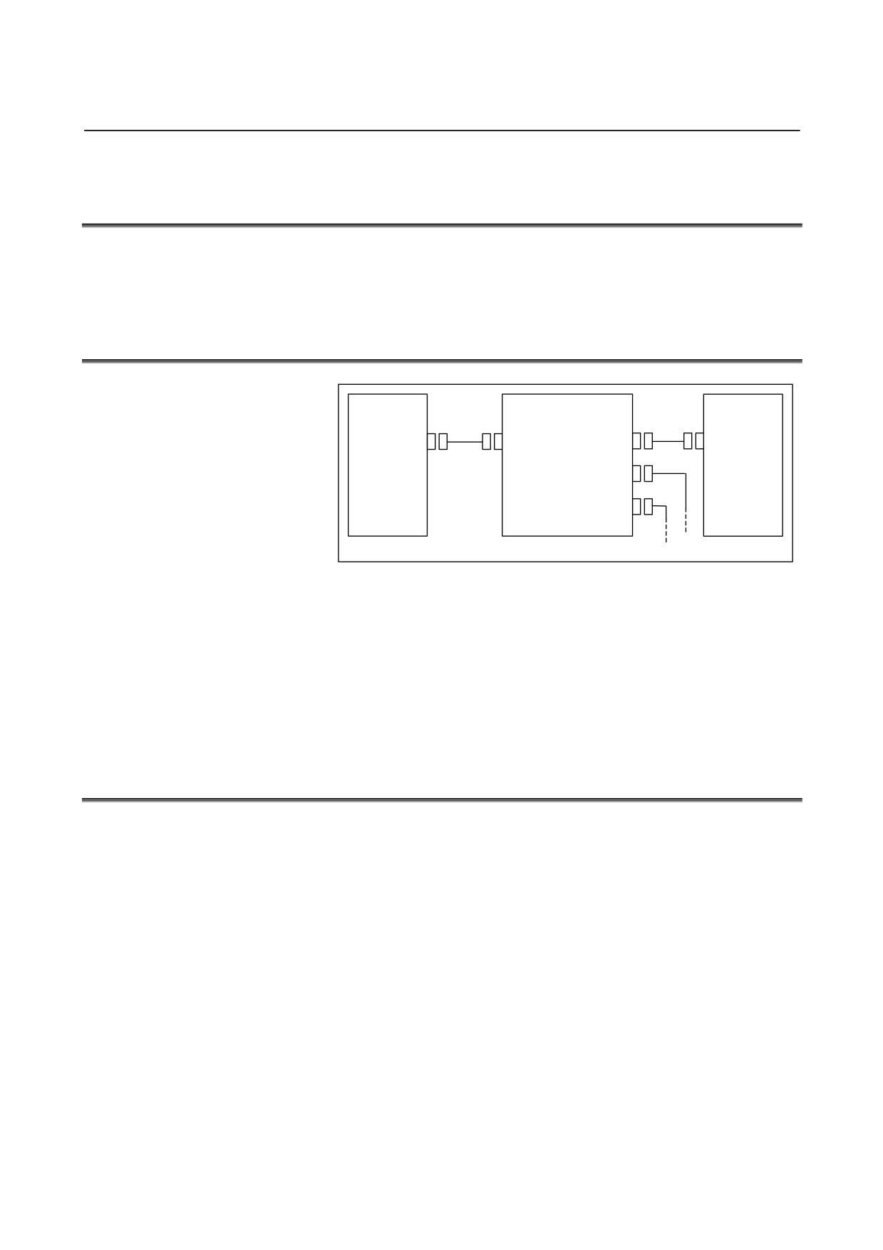
11.I/O Link DUMMY UNIT
11.7 CONNECTION DIAGRAMS
11.7.1 When not Connecting FANUC I/O Link Dummy Units in Series
CNC
CNC
Cell controller
Cell controller
JD1A
JD1A
FANUC I/O Link
dummy unit
Operator's panel
Operator's panel
connection unit
connection unit
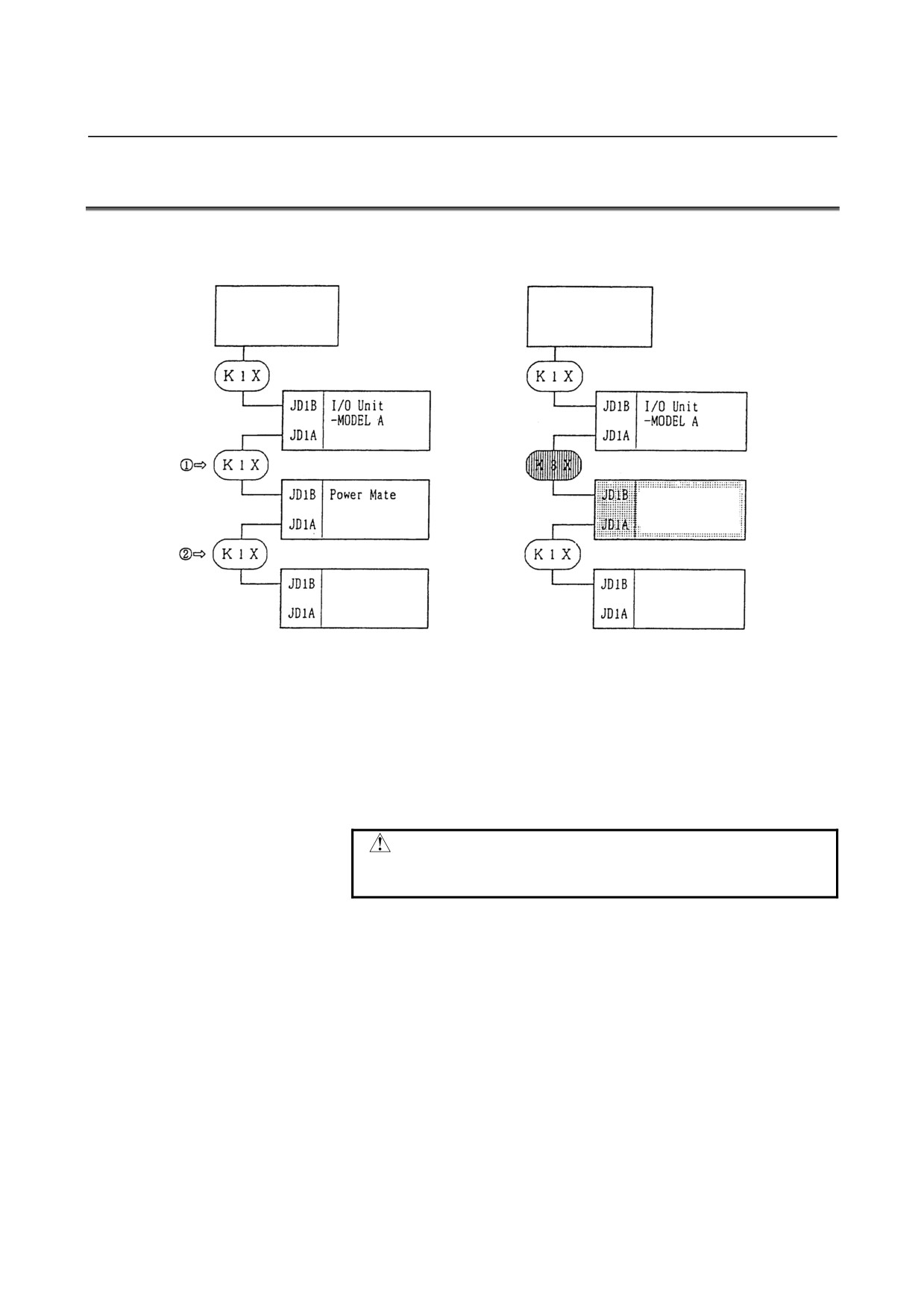
Fig. 11.7.1 Example of Using the FANUC I/O Link Dummy Unit
(in Place of the Power Mate)
(1) Replacing a cable
The FANUC I/O Link dummy unit is supplied with power from
the preceding or following group via a K3X cable. So, the K1X
cable at either JD1A or JD1B of the dummy unit must be replaced
with the K3X cable (c or d in Fig. 11.7.1).
CAUTION
Do not attach a K3X cable to JD1A and JD1B
simultaneously.
(2) Cable length
K1X cable: 10 m (maximum) (for cabling within the same cabinet,
up to 15 m)
K3X cable: 2 m (maximum)
- 183 -
11.I/O Link DUMMY UNIT
CONNECTION
B-61813E/04
11.7.2 Connecting FANUC I/O Link Dummy Units in Series
FANUC
FANUC
FANUC
FANUC
Unit with
Unit with
I/O Link
I/O Link
I/O Link
I/O Link
FANUC I/O
FANUC I/O
dummy
dummy
dummy
dummy
Link
Link
unit
unit
unit
unit
Up to two units
Up to ten
Up to two units
Up to two meters
meters
Up to two meters
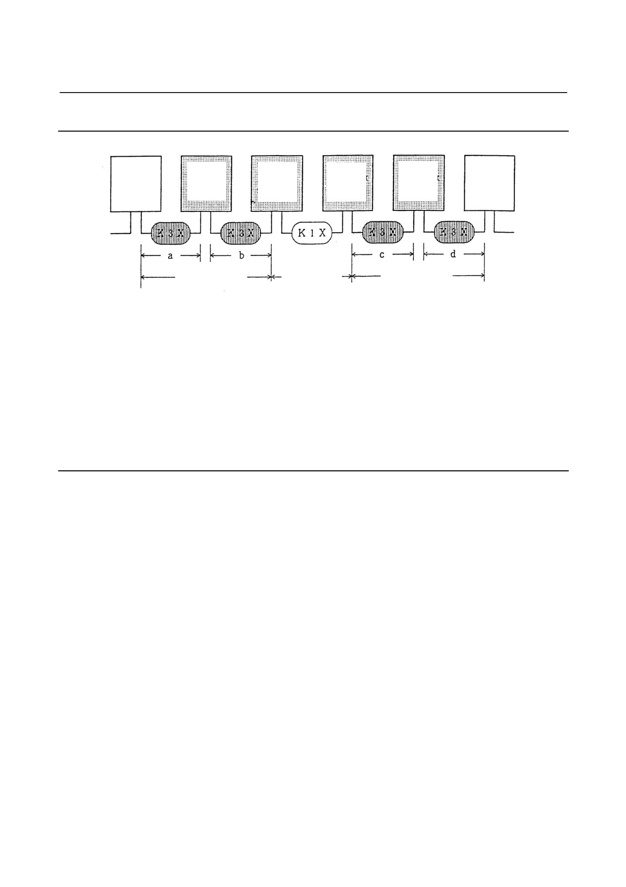
Fig. 11.7.2
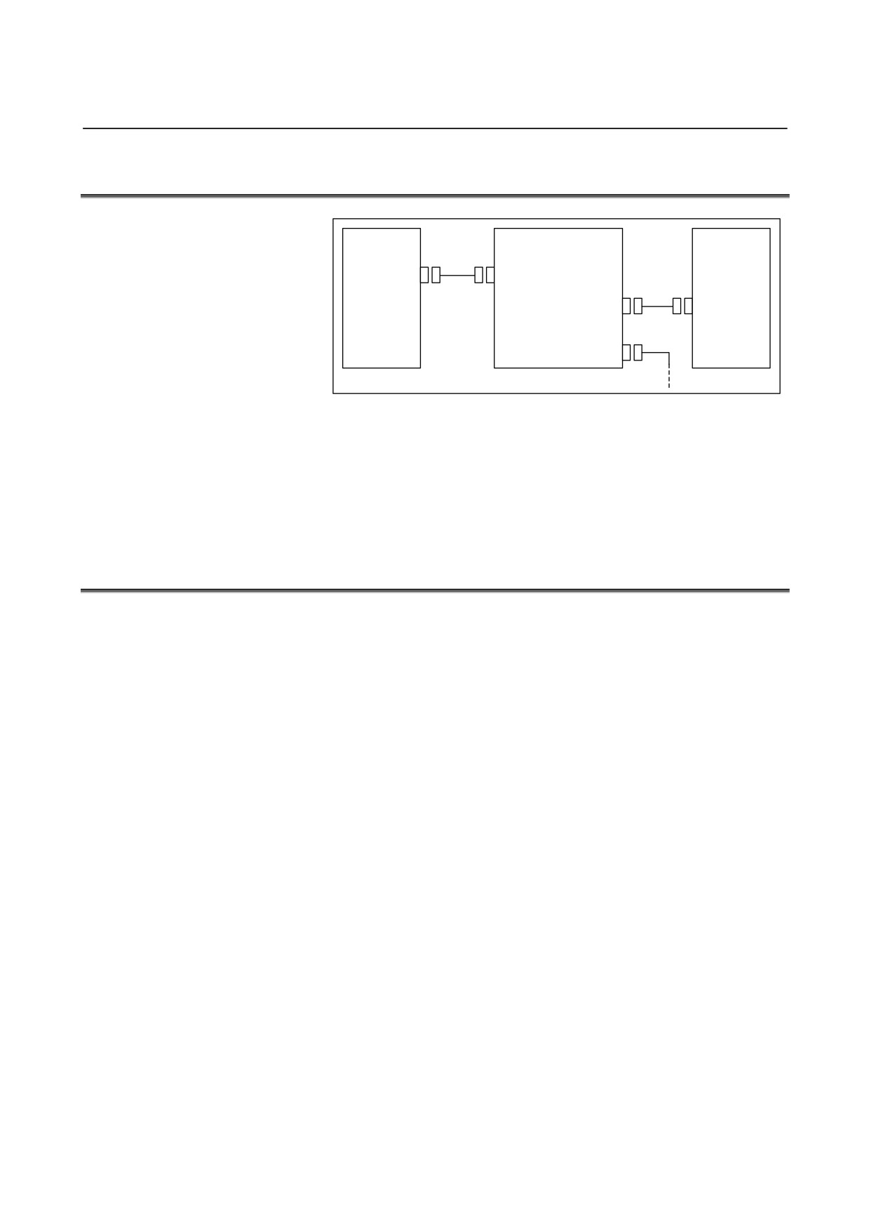
(1) Number of FANUC I/O Link dummy units that can be used in
succession
Up to two FANUC I/O Link dummy units can be connected via a
K3X cable to a unit that supplies power to them. (See Fig. 11.7.2.)
(2) Cable length
K1X cable: 10 m (maximum) (for cabling within the same cabinet,
up to 15 m)
K3X cable: 2 m (maximum) in total (a + b ≤ 2 m and c + d ≤ 2 m)
11.7.3 Grounding
Ground the case of the FANUC I/O Link dummy unit.
- 184 -
B-61813E/04
CONNECTION
11.I/O Link DUMMY UNIT
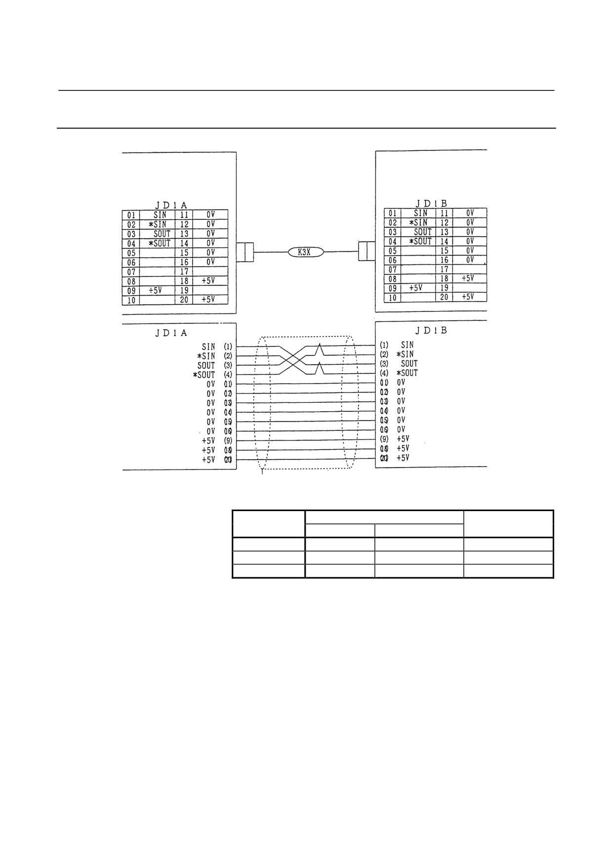
11.7.4 K3X Cable
CNC, cell controller,
FANUC I/O Link dummy
AIF01A, etc., or FANUC I/O
unit, AIF01A, or the like
Link dummy unit
Connector (see the diagram
below.)
•
Cable connector
Manufacturer
Pin
Housing
Soldering type
Crimping type
Honda Tsushin
PCR-E20FS
PCR-E20FA
PCR-V20LA
Hirose Electric
FI-40-20S
FI-30-20S
FI-20-CV2
Fujitsu
-
FCN-247J020-G/E
FCN-240C020-Y/S
•
Use twisted-pair wires for the SIN, *SIN, SOUT, and *SOUT
signals.
•
Recommended wires : A66L-0001-0284#10P (twisted-pair wires
with common shielding)
•
Maximum cable length : 2 m (when recommended wires are used)
•
Do not connect a wire to an idle pin.
•
Connect the cable shielding to the grounding plate of the cabinet
via a metal cable clamp at JD1A. (See the applicable CNC or cell
controller connection manual.)
- 185 -
12.TWO-CHANNEL I/O Link CONNECTOR ADAPTER CONNECTION
B-61813E/04
12
TWO-CHANNEL I/O Link CONNECTOR
ADAPTER
- 186 -
B-61813E/04
CONNECTION
12.TWO-CHANNEL I/O Link CONNECTOR ADAPTER
12.1 OVERVIEW
The FANUC Series 16i/18i/21i-MODEL B CNC has two FANUC I/O
Link interface channels. These channels make it possible to increase the
number of I/O points from 1024/1024 to 2048/2048.
This chapter explains how to connect a 2-channel I/O Link connector
adapter required in using the I/O Link 2-channel function.
NOTE
Using this function on the 16i/18i/21i-MODEL B
mentioned above requires specifying the
PMC-SB6/-SB7.
This function cannot be used with the PMC on the
loader control board.
12.2 CONNECTION FOR USE OF TWO FANUC I/O Link
CHANNELS
Two channels' worth of I/O Link signals are allocated to the I/O Link
connector (JD44A) of the Series 16i/18i/21i-MODEL B CNC.
Three channels' worth of I/O Link signals are allocated to the I/O Link
connector (JD51A) of the Series 30i/31i/32i CNC.
To use two I/O Link channels in the above CNC, branch out the I/O
Link (JD44A/JD51A connector signals), using an I/O Link connector
adapter.
(See Chapter 13 for explanations about how to use the I/O Link
4-channel function with the Series 30i/31i/32i.)
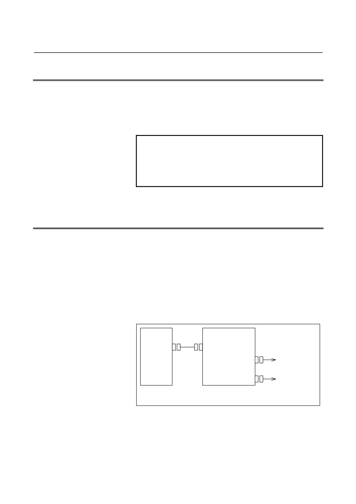
Connection
CNC unit
2-channel I/O Link
connector adapter
JD44A/
JD51A
JD44B
FANUC I/O Link
JD1A-1
channel 1
JD1A-2
FANUC I/O Link
channel 2
Connections ahead of the I/O Link connector adapter are
the same as for the conventional FANUC I/O Link.
2-channel I/O Link connector adapter: A20B-1007-0680
Restriction
When 2 I/O Link channels are used, the FANUC I/O Unit-MODEL B
supports connection of up to 8 groups for the 2 channels.
- 187 -
12.TWO-CHANNEL I/O Link CONNECTOR ADAPTER CONNECTION
B-61813E/04
12.3 CONNECTING THE CNC WITH TWO-CHANNEL I/O Link
CONNECTOR ADAPTER
Connecting the Series 16i/18i/21i-MODEL B CNC
CNC unit
2-channel I/O Link connector
JD44A
adapter JD44B
(such as PCR-E20MDK-SL-A)
(PCR-E20MDT)
1
SIN1
11
0V
1
SIN1
11
0V
2
*SIN1
12
0V
2
*SIN1
12
0V
3
SOUT1
13
0V
3
SOUT1
13
0V
4
*SOUT1
14
0V
4
*SOUT1
14
0V
5
SIN2
15
0V
5
SIN2
15
0V
6
*SIN2
16
0V
6
*SIN2
16
0V
7
SOUT2
17
7
SOUT2
17
8
*SOUT2
18
(+5V)
8
*SOUT2
18
(+5V)
9
(+5V)
19
(+24V)
9
(+5V)
19
10
(+24V)
20
(+5V)
10
20
(+5V)
Connecting the Series 30i/31i/32i CNC
CNC unit
2-channel I/O Link connector
JD51A
adapter JD44B
(such as PCR-E20MDK-SL-A)
(PCR-E20MDT)
1
SIN1
11
0V
1
SIN1
11
0V
2
*SIN1
12
0V
2
*SIN1
12
0V
3
SOUT1
13
0V
3
SOUT1
13
0V
4
*SOUT1
14
0V
4
*SOUT1
14
0V
5
SIN2
15
0V
5
SIN2
15
0V
6
*SIN2
16
(*SIN3)
6
*SIN2
16
7
SOUT2
17
(SIN3)
7
SOUT2
17
8
*SOUT2
18
(+5V)
8
*SOUT2
18
(+5V)
9
(+5V)
19
(SOUT3)
9
(+5V)
19
10
(*SOUT3)
20
(+5V)
10
20
(+5V)
The +5-V pin is intended to perform optical fiber transmission using an
optical I/O Link adapter. When using no optical I/O Link adapter, keep
the +5-V pin unconnected. (See Section 10.6 for details.)
When the Series 30i/31i/32i CNC is used, pins 10, 16, 17, and 19 are
reserved for I/O Link channel 3. When connecting these CNC units
with a 2-channel I/O Link adapter, do not connect anything to these
pins.
Do not connect anything to the +24-V pin.
- 188 -
B-61813E/04
CONNECTION
12.TWO-CHANNEL I/O Link CONNECTOR ADAPTER
12.4
CABLING
CNC unit
I/O Link connector
JD44A,JD51A
adapter JD44B
1
3
SIN1
SOUT1
2
4
*SIN1
*SOUT1
3
1
SIN1
SOUT1
4
2
*SOUT1
*SIN1
5
7
SOUT2
SIN2
6
8
*SIN2
*SOUT2
7
5
SOUT2
SIN2
8
6
*SIN2
*SOUT2
11
11
0V
0V
12
12
0V
0V
13
13
0V
0V
14
14
0V
0V
15
15
0V
0V
16
16
[0V]
(*2)
(*2)
[0V]
18
18
(*1) (+5V)
(+5V) (*1)
20
20
(+5V) (*1)
(*1) (+5V)
9
9
(*1) (+5V)
(+5V) (*1)
Shield
*1 When using no optical I/O Link adapter, do not connect anything to the +5-V pin.
*2 If the CNC of interest is the Series 30i/31i/32i, do not connect anything to pin 16.
Recommended cable-end connector:
PCR-E20FA (manufactured by HONDA TSUSHIN)
FCN-247J020-G/E (manufactured by Fujitsu)
52622-2011 (manufactured by Molex)
Recommended cable (wire): A66L-0001-0284#10P
12.5 CONNECTING TWO-CHANNEL I/O Link CONNECTOR
ADAPTER TO I/O Units FOR THE FANUC I/O Link
The 2-channel I/O Link connector adapter can be connected to diverse
I/O Units in the same manner as for the conventional FANUC I/O Link.
- 189 -
12.TWO-CHANNEL I/O Link CONNECTOR ADAPTER CONNECTION
B-61813E/04
12.6 CABLE LENGTH
CNC unit
2-channel I/O Link
I/O Unit
connector adapter
JD44A/
LA
JD51A
JD44B
LB1
JD1A-1
JD1B
LB2
JD1A-2
The sum (LA + LB) of the cable length LA between the CNC unit
(JD44A) and 2-channel I/O Link connector adapter (JD44B) and the
cable length LB (= LB1 + LB2) between the I/O Link connector adapter
(JD1A-1 or JD1A-2) and I/O Unit (JD1B) shall not be longer than 10 m.
For cabling within the same cabinet, the sum can be up to 15 m.
12.7 INSTALLING TWO-CHANNEL I/O Link CONNECTOR
ADAPTER
Install the 2-channel I/O Link connector adapter in a cabinet that can be
sealed on the same level as for the CNC unit.
- 190 -
B-61813E/04
CONNECTION
12.TWO-CHANNEL I/O Link CONNECTOR ADAPTER
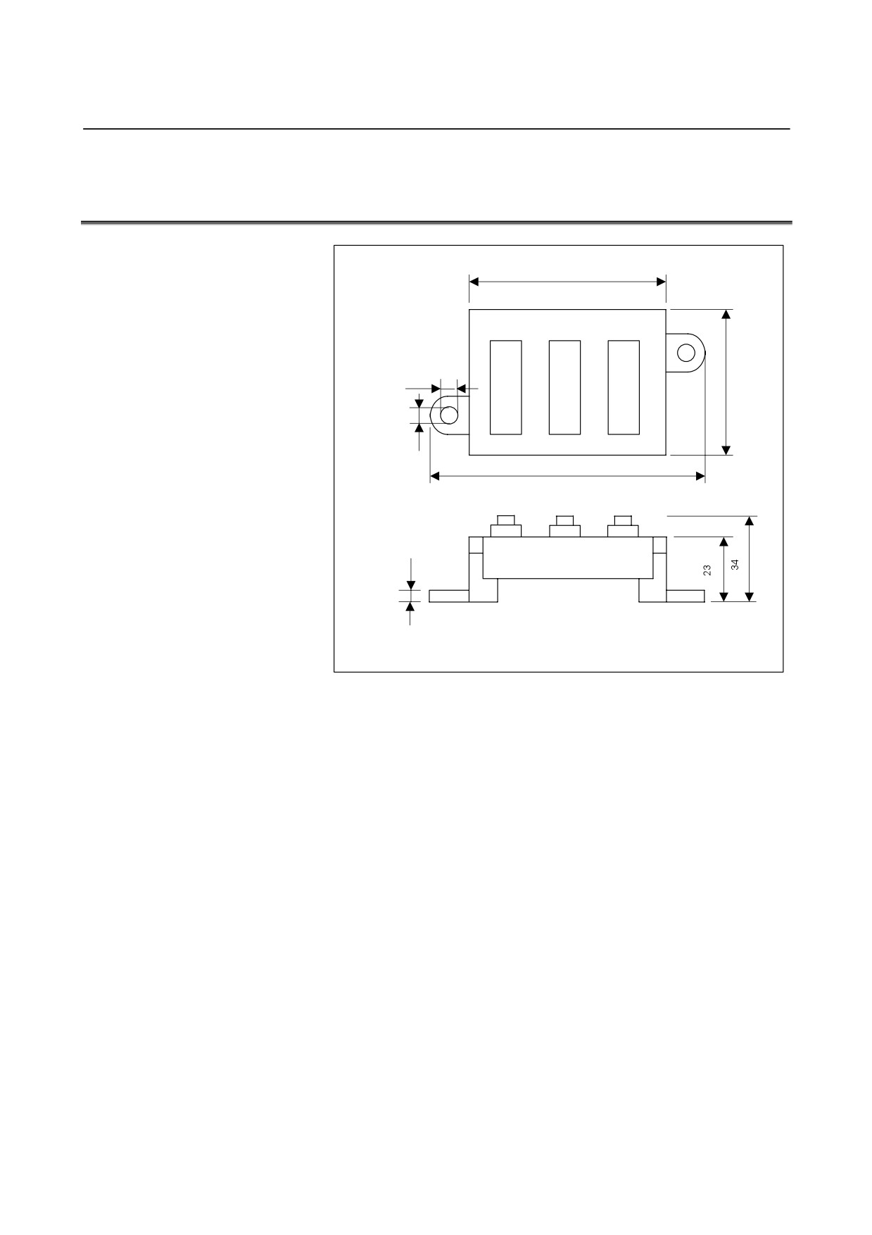
12.8 OUTSIDE DIMENSIONS OF TWO-CHANNEL I/O Link
CONNECTOR ADAPTER
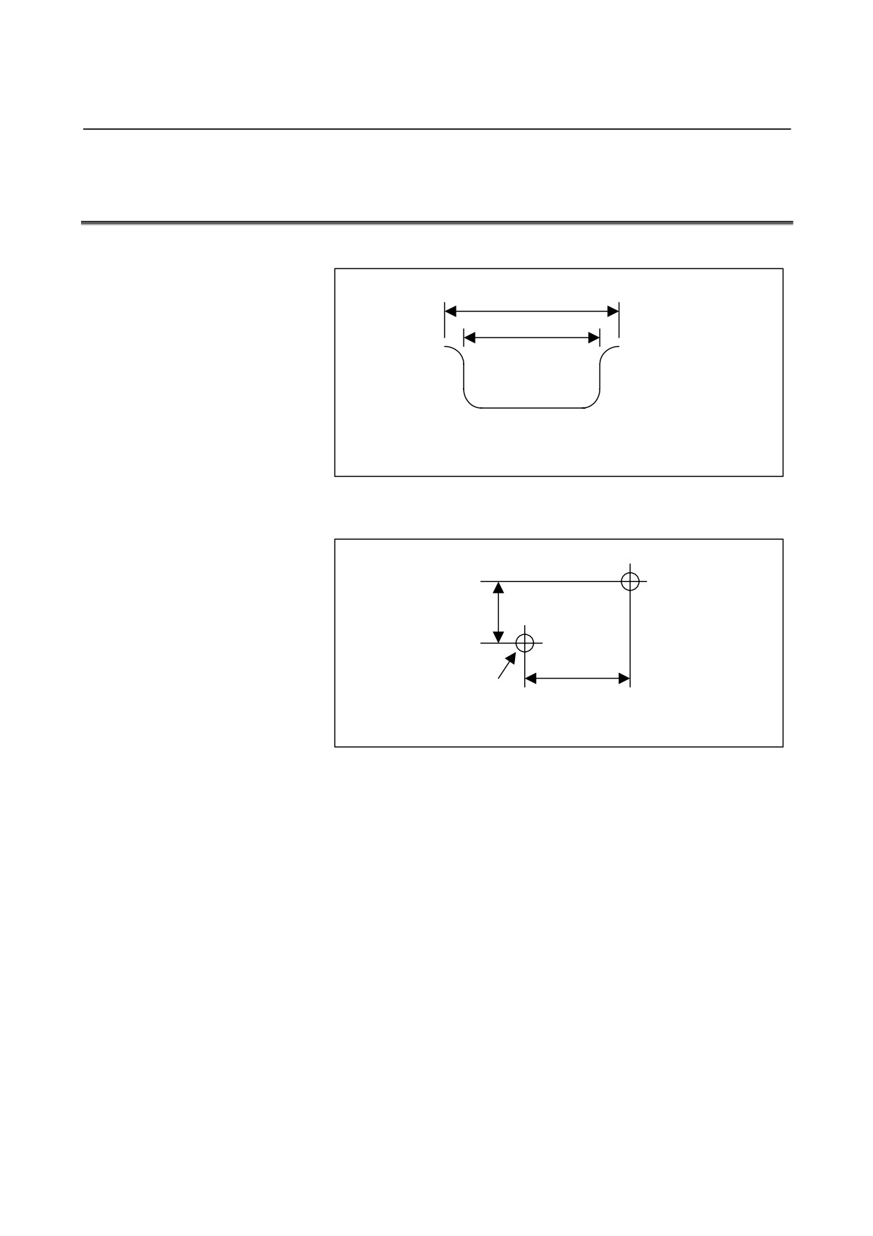
60
JD44B
JD1A-1
JD1A-2
5.1
45
4.1
81
4.5
Unit : mm
Weight : 60g
Allow a space of about 10 cm above the adapter so that cables can be
laid and connected.
- 191 -
12.TWO-CHANNEL I/O Link CONNECTOR ADAPTER CONNECTION
B-61813E/04
12.9 MOUNTING TWO-CHANNEL I/O Link CONNECTOR
ADAPTER
Mounting on the DIN rail
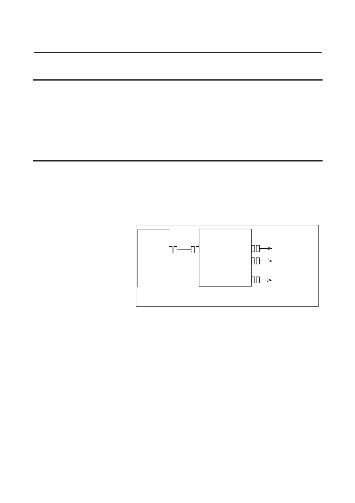
35
25
Unit: mm
Recommended DIN rail
Using screws
11.6
70
2-M4
Unit: mm
Mounting hole dimension and layout diagram
- 192 -
B-61813E/04
CONNECTION
13.THREE-CHANNEL I/O Link CONNECTOR ADAPTER
13
THREE-CHANNEL I/O Link CONNECTOR
ADAPTER
- 193 -
13.THREE-CHANNEL I/O Link CONNECTOR ADAPTER CONNECTION
B-61813E/04
13.1 OVERVIEW
With the FANUC Series 30i/31i/32i CNC, it is possible to use up to 4
FANUC I/O Link interface channels. These channels make it possible
to increase the number of I/O points from 1024/1024 to 4096/4096.
This chapter explains how to connect a 3-channel I/O Link connector
adapter required in using the FANUC I/O Link 4-channel function.
13.2 CONNECTION FOR USE OF FOUR FANUC I/O Link
CHANNELS
Three channels' worth of I/O Link signals are allocated to the I/O Link
connector (JD51A) of the Series 30i/31i/32i CNC.
To use the I/O Link
4-channel function, branch out the JD51A
connector signals, using a 3-channel I/O Link connector adapter.
(Channel 4 is allocated on the optional board.)
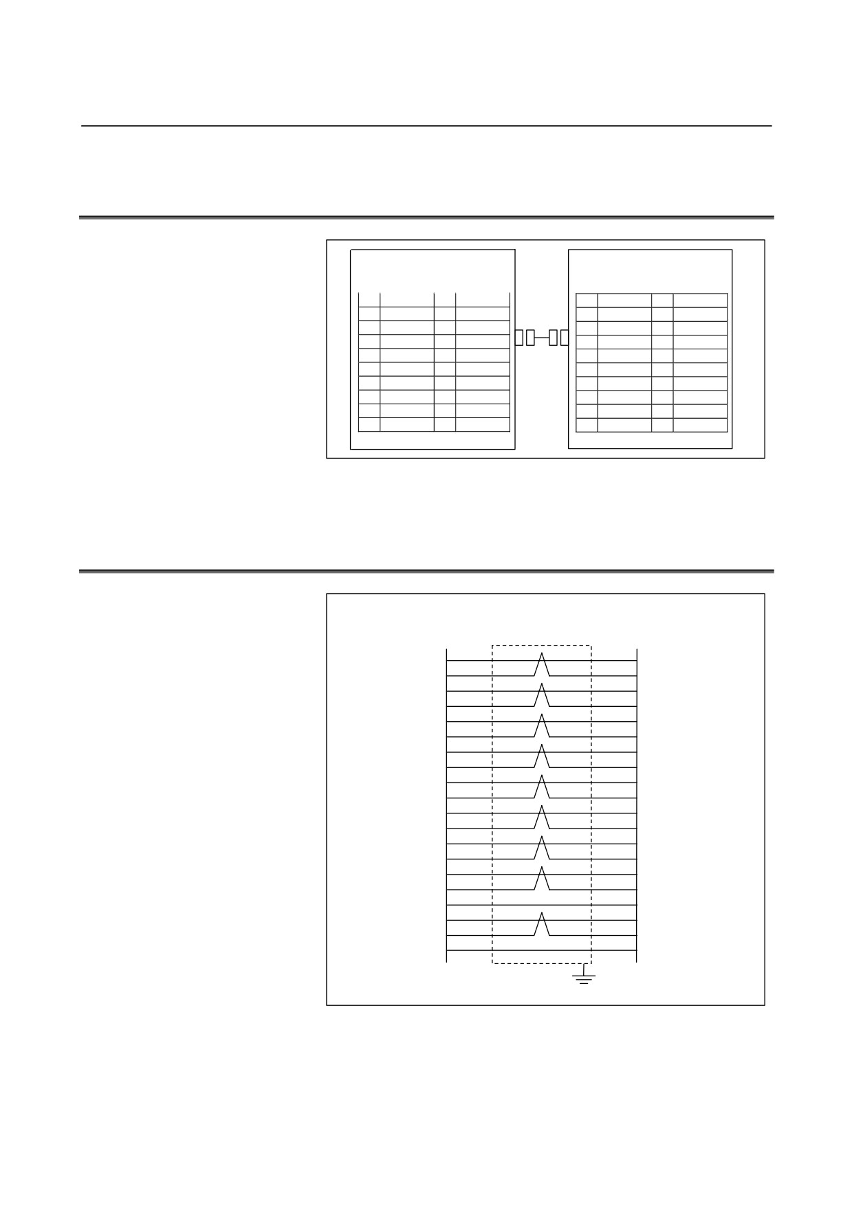
Connection
CNC unit
3-channel I/O Link
connector adapter
FANUC I/O Link
JD51A
JD51B
JD44A-1
channel 1 and
channel 2
FANUC I/O Link
JD44A-2
channel 2 and
channel 3
JD1A
FANUC I/O Link
channel 3
Connections ahead of the 3-channel I/O Link connector adapter are the same as for
the conventional FANUC I/O Link.
3-channel I/O Link connector adapter: A20B-1008-0360
Restriction
The FANUC I/O Unit-MODEL B supports connection of up to 8
groups for the 4 channels.
- 194 -
B-61813E/04
CONNECTION
13.THREE-CHANNEL I/O Link CONNECTOR ADAPTER
13.3
CONNECTING THE CNC WITH THREE-CHANNEL I/O Link
CONNECTOR ADAPTER
CNC unit
3-channel I/O Link connector
JD51A
adapter JD51B
(such as PCR-E20MDK-SL-A)
(PCR-E20MDT)
1
SIN1
11
0V
1
SIN1
11
0V
2
*SIN1
12
0V
2
*SIN1
12
0V
3
SOUT1
13
0V
3
SOUT1
13
0V
4
*SOUT1
14
0V
4
*SOUT1
14
0V
5
SIN2
15
0V
5
SIN2
15
0V
6
*SIN2
16
*SIN3
6
*SIN2
16
*SIN3
7
SOUT2
17
SIN3
7
SOUT2
17
SIN3
8
*SOUT2
18
(+5V)
8
*SOUT2
18
(+5V)
9
(+5V)
19
SOUT3
9
(+5V)
19
SOUT3
10
*SOUT3
20
(+5V)
10
*SOUT3
20
(+5V)
The +5-V pin is intended to perform optical fiber transmission using an
optical I/O Link adapter. When using no optical I/O Link adapter, keep
the +5-V pin unconnected.
13.4
CABLING
3-channel I/O Link
CNC unit
connector adapter
JD51A
JD51B
SIN1
1
3
SOUT1
*SIN1
2
4
*SOUT1
SOUT1
3
1
SIN1
*SOUT1
4
2
*SIN1
SIN2
5
7
SOUT2
*SIN2
6
8
*SOUT2
SOUT2
7
5
SIN2
*SOUT2
8
6
*SIN2
SIN3
17
19
SOUT3
*SIN3
16
10
*SOUT3
SOUT3
19
17
SIN3
*SOUT3
10
16
*SIN3
0V
11
11
0V
0V
12
12
0V
0V
13
13
0V
0V
14
14
0V
0V
15
15
0V
(+5V)
9
9
(+5V)
(+5V)
18
18
(+5V)
(+5V)
20
20
(+5V)
Shield
(*) When using no optical I/O Link adapter, do not connect anything to the +5-V pin.
Recommended cable-end connector:
PCR-E20FA (manufactured by HONDA TSUSHIN)
FCN-247J020-G/E (manufactured by Fujitsu)
52622-2011 (manufactured by Molex)
Recommended cable (wire): A66L-0001-0284#10P
- 195 -
13.THREE-CHANNEL I/O Link CONNECTOR ADAPTER CONNECTION
B-61813E/04
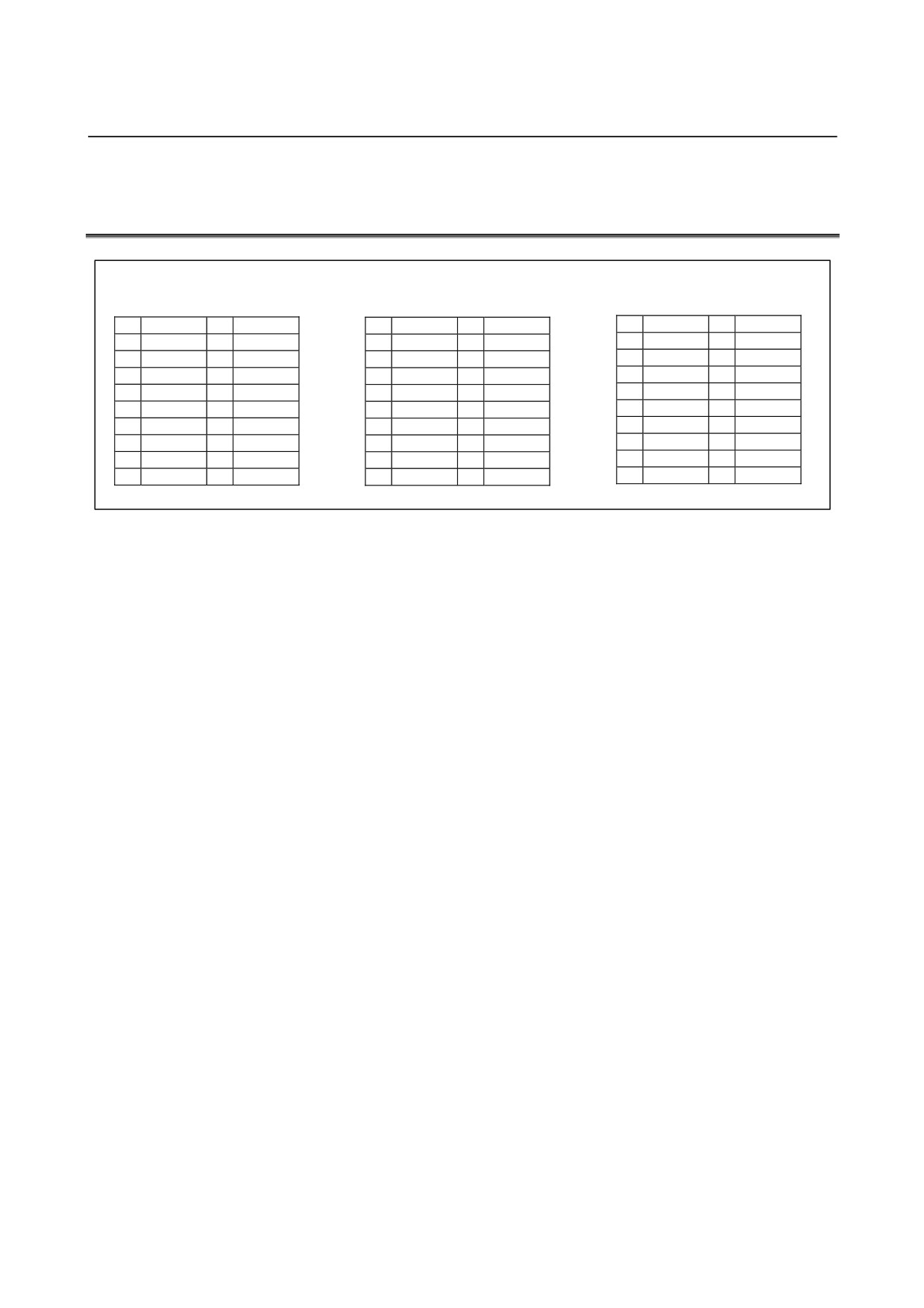
13.5 ALLOCATING THREE-CHANNEL I/O Link CONNECTOR
ADAPTER SIGNALS
3-channel I/O Link connector
adapter JD44A-1
JD44A-2
JD1A
(PCR-E20MDT)
(PCR-E20MDT)
(PCR-E20MDT)
1
SIN1
11
0V
1
SIN2
11
0V
1
SIN3
11
0V
2
*SIN1
12
0V
2
*SIN2
12
0V
2
*SIN3
12
0V
3
SOUT1
13
0V
3
SOUT2
13
0V
3
SOUT3
13
0V
4
*SOUT1
14
0V
4
*SOUT2
14
0V
4
*SOUT3
14
0V
5
SIN2
15
0V
5
SIN3
15
0V
5
15
0V
6
*SIN2
16
0V
6
*SIN3
16
0V
6
16
0V
7
SOUT2
17
7
SOUT3
17
7
17
8
*SOUT2
18
(+5V)
8
*SOUT3
18
(+5V)
8
18
(+5V)
9
(+5V)
19
9
(+5V)
19
9
(+5V)
19
10
20
(+5V)
10
20
(+5V)
10
20
(+5V)
- 196 -
B-61813E/04
CONNECTION
13.THREE-CHANNEL I/O Link CONNECTOR ADAPTER
13.6
CONNECTING THREE-CHANNEL I/O Link CONNECTOR
ADAPTER SIGNAL TO EACH CHANNEL
The 3-channel I/O Link connector adapter can be connected to each I/O
Unit in the same manner as for the conventional I/O Link. However,
note the following points:
The signals for I/O Link channels 1 and 2 are allocated to the JD44A-1
connector. The signals for I/O Link channels 2 and 3 are allocated to the
JD44A-2 connector.
The JD1A connector is dedicated to I/O Link channel 3.
(1) To branch out the 3-channel signals, an ordinary I/O Link cable is
connected to each of the JD44A-1, JD44A-2, and JD1A. In this
case, the JD44A-1, JD44A-2, and JD1A correspond, respectively,
to channels 1, 2, and 3.
(2) To extend channels 1 and 2 together, the I/O Link connector
adapter
(A20B-1007-0680) is connected to the JD44A-1 to
separate channels 1 and 2 from each other after the adapter.
To use channel 3, connect it to the JD1A; the JD44A-2 cannot be
used.
(3) To extend channels 2 and 3 together, the I/O Link connector
adapter
(A20B-1007-0680) is connected to the JD44A-2 to
separate channels 2 and 3 from each other after the adapter.
To use channel 1, connect it to the JD44A-1; the JD1A cannot be
used.
(1) When branching out the 3-channel signals
CNC
3-channel I/O Link
connector adapter
JD51A
JD51B
JD44A-1
Channel 1
Channel 2
JD44A-2
JD1A
Channel 3
- 197 -
13.THREE-CHANNEL I/O Link CONNECTOR ADAPTER CONNECTION
B-61813E/04
(2) When extending channels 1 and 2 together
CNC
3-channel I/O Link
I/O Link connector
connector adapter
adapter
(A20B-1007-0680)
JD51A
JD51B
JD44A-1
JD44B
JD1A-1
Channel 1
JD1A-2
Channel 2
Unusable
JD44A-2
JD1A
Channel 3
(3) When extending channels 2 and 3 together
CNC
3-channel I/O Link
connector adapter
Channel 1
JD51A
JD51B
JD44A-1
I/O Link connector
adapter
(A20B-1007-0680)
JD44A-2
JD44B
JD1A-1
Channel 2
JD1A-2
Channel 3
JD1A
Unusable
- 198 -
B-61813E/04
CONNECTION
13.THREE-CHANNEL I/O Link CONNECTOR ADAPTER
13.7
CONNECTING THREE-CHANNEL I/O Link CONNECTOR
ADAPTER TO TWO-CHANNEL I/O Link CONNECTOR
ADAPTER
3-channel I/O Link connector
2-channel I/O Link connector
adapter JD44A-1/ JD44A-2
adapter JD44B
(such as PCR-E20MDK-SL-A)
(PCR-E20MDT)
1
SIN1
11
0V
1
SIN1
11
0V
2
*SIN1
12
0V
2
*SIN1
12
0V
3
SOUT1
13
0V
3
SOUT1
13
0V
4
*SOUT1
14
0V
4
*SOUT1
14
0V
5
SIN2
15
0V
5
SIN2
15
0V
6
*SIN2
16
6
*SIN2
16
7
SOUT2
17
7
SOUT2
17
8
*SOUT2
18
(+5V)
8
*SOUT2
18
(+5V)
9
(+5V)
19
9
(+5V)
19
10
20
(+5V)
10
20
(+5V)
The +5-V pin is intended to perform optical fiber transmission using an
optical I/O Link adapter. When using no optical I/O Link adapter, keep
the +5-V pin unconnected.
Cabling
3-channel I/O Link
2-channel I/O Link
connector adapter
connector adapter
JD44A-1
JD44B
SIN1
1
3
SOUT1
*SIN1
2
4
*SOUT1
SOUT1
3
1
SIN1
*SOUT1
4
2
*SIN1
SIN2
5
7
SOUT2
*SIN2
6
8
*SOUT2
SOUT2
7
5
SIN2
*SOUT2
8
6
*SIN2
0V
11
11
0V
0V
12
12
0V
0V
13
13
0V
0V
14
14
0V
0V
15
15
0V
(+5V)
9
9
(+5V)
(+5V)
18
18
(+5V)
(+5V)
20
20
(+5V)
Shield
(*) When using no optical I/O Link adapter, do not connect anything to the +5-V pin.
Recommended cable-end connector:
PCR-E20FA (manufactured by HONDA TSUSHIN)
FCN-247J020-G/E (manufactured by Fujitsu)
52622-2011 (manufactured by Molex)
Recommended cable (wire): A66L-0001-0284#10P
- 199 -
13.THREE-CHANNEL I/O Link CONNECTOR ADAPTER CONNECTION
B-61813E/04
13.8 CONNECTING THREE-CHANNEL I/O Link CONNECTOR
ADAPTER TO I/O Units FOR THE FANUC I/O Link
The 3-channel I/O Link connector adapter can be connected to diverse
I/O Units in the same manner as for the conventional FANUC I/O Link.
13.9 CABLE LENGTH
CNC unit
3-channel I/O Link
I/O Unit
connector adapter
LA
LB1
JD51B
JD44A-1
JD1B
JD51A
LB2
JD44A-2
LB3
JD1A
The sum (LA + LB) of the cable length LA between the CNC unit
(JD51A) and I/O Link connector adapter (JD51B) and the cable length
LB (=LB1+LB2+LB3) between the I/O Link connector adapter (JD44A-1,
JD44A-2, or JD1A) and I/O Unit (JD1B) shall not be longer than 10 m.
For cabling within the same cabinet, the sum can be up to 15 m.
13.10 INSTALLING THREE-CHANNEL I/O Link CONNECTOR
ADAPTER
Install the 3-channel I/O Link connector adapter in a cabinet that can be
sealed on the same level as for the CNC unit.
- 200 -
B-61813E/04
CONNECTION
13.THREE-CHANNEL I/O Link CONNECTOR ADAPTER
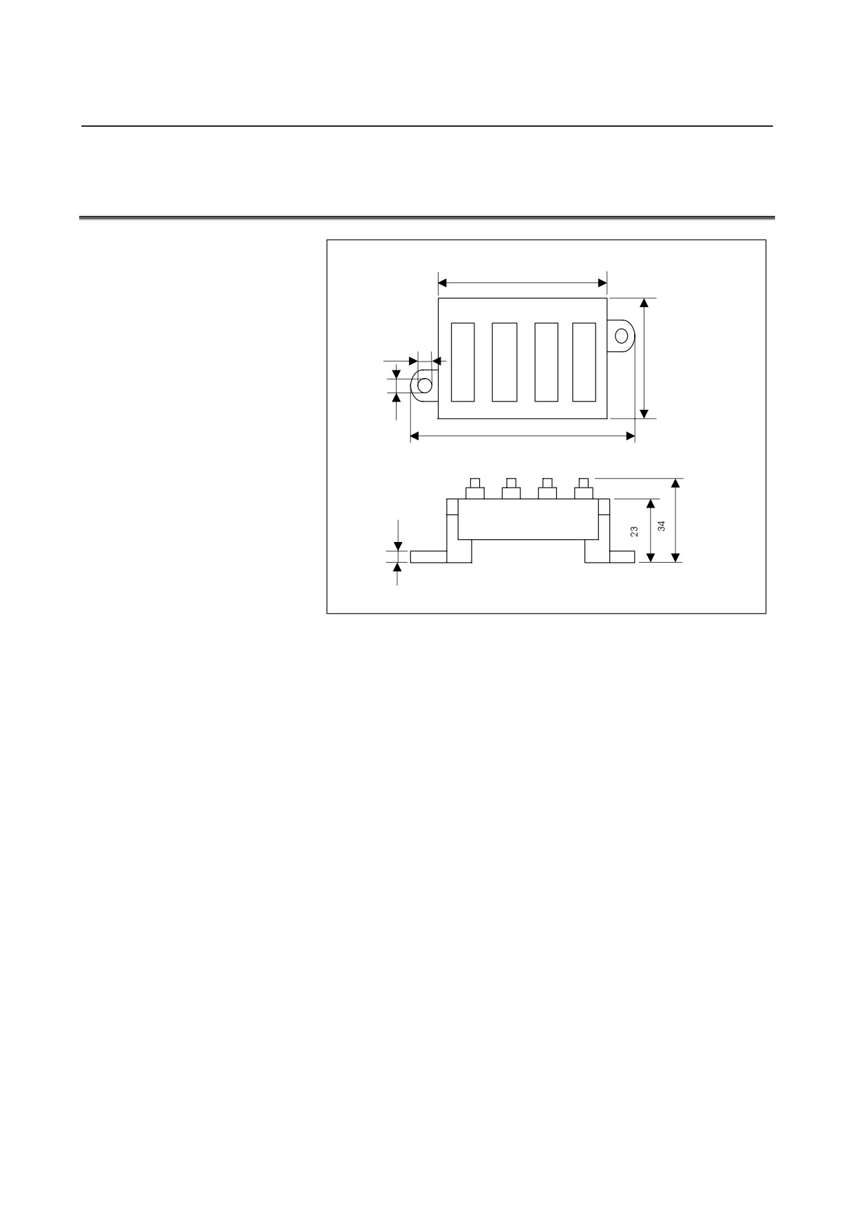
13.11 OUTSIDE DIMENSIONS OF THREE-CHANNEL I/O Link
CONNECTOR ADAPTER
80
JD51B
JD44A-1 JD44A-2
JD1A
5.1
45
4.1
101
4.5
Unit: mm
Weight: 90g
Allow a space of about 10 cm above the adapter so that cables can be
laid and connected.
- 201 -
13.THREE-CHANNEL I/O Link CONNECTOR ADAPTER CONNECTION
B-61813E/04
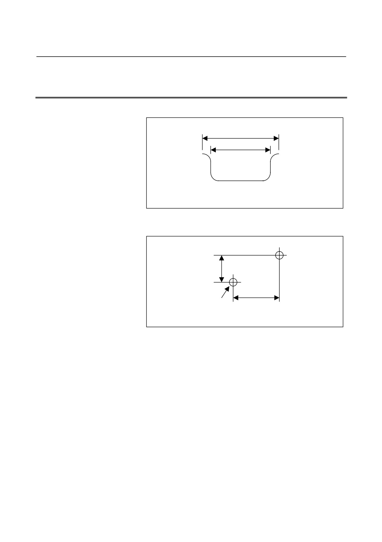
13.12 MOUNTING THREE-CHANNEL I/O Link CONNECTOR
ADAPTER
Mounting on the DIN rail
35
25
Unit: mm
Recommended DIN rail
Using screws
11.6
90
2-M4
Unit: mm
Mounting hole dimension and layout diagram
- 202 -
B-61813E/04
CONNECTION
14.SAFETY FOR USING AC
14
SAFETY FOR USING AC
IF AC output module or AC input module is used, Section 14.1 is
recommended for safety. When using it for a machine directed to the
European market, carefully observe the descriptions in Section 14.1 [as
per EN50178].
- 203 -
14.SAFETY FOR USING AC
CONNECTION
B-61813E/04
14.1
ENVIRONMENT FOR INSTALLATION
14.1.1
Installation Category (Overvoltage Category)
Install the unit in the environment of Installation Category II
(Overvoltage Category II) or better. [DIN VDE0110]
The available impulse surge level to the ground that appears in the
power source is 2.5kV maximum.
(100VAC system power source is needed in AC input module
According to the standard, the available impulse surge level to the
ground is 1.5kV for this power source (voltage of which is 150VAC or
less). However, for this module, the available impulse surge level to the
ground that appears in the power source is 2.5 kV.)
Generally, an isolation transformer used for the main power source is
regarded as an effective surge filter.
The class of the 16-point relay output module (AOR16G) is set to
installation category (overvoltage category) I.
(Keep any impulse voltage to ground that may appear on the AC power
to within 1.5 kV.)
The class for the 8-point relay output module (AOR08G), AC output
module, and AC input module is set to installation category
(overvoltage category) II.
14.1.2
Pollution Degree
Install the unit in the environment of pollution degree 2 or better.
[EN50178]
In cabinet of IP-54 or better (described in Section 3.1), it can be
considered as pollution degree 2 or better usually. The IP degree
required is depended on the circumstances of machine tool, so select the
adequate degree in accordance with such environment.
- 204 -
1.OVERVIEW
MAINTENANCE
B-61813E/04
1.1
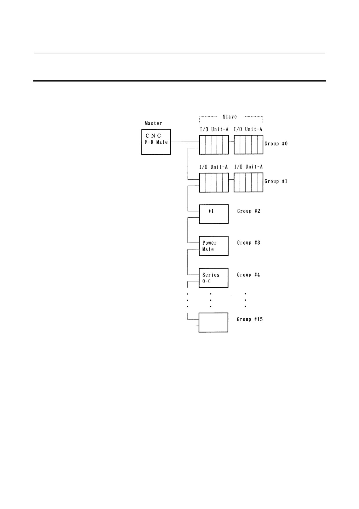
SYSTEM CONFIGURATION
I/O Unit-A is connected to a CNC and cell controller through a
high-speed serial interface, I/O Link.
(*1) Operator’s panel connection unit
(1) The I/O Link consists of a master and slaves.
Master: Series0-C, Series15/16/18/20/21,
Series15i/16i/18i/20i/21i/30i/31i/32i/0i,
Power Mate-D/H, Power Mate i-D/H, F-D Mate
Slave:
I/O Unit-A, I/O Unit-B, Power Mate, operator's panel
connection unit, and Series 0-C, and so on
(2) One I/O Link can connect to up 16 groups of slaves. If the master
is not a CNC, one slave group can contain up to 2 of I/O Unit A (2
base units). If the master is the F-D Mate, however, one group can
contain up to 4 I/O Units.
- 208 -
B-61813E/04
MAINTENANCE
1.OVERVIEW
1.2
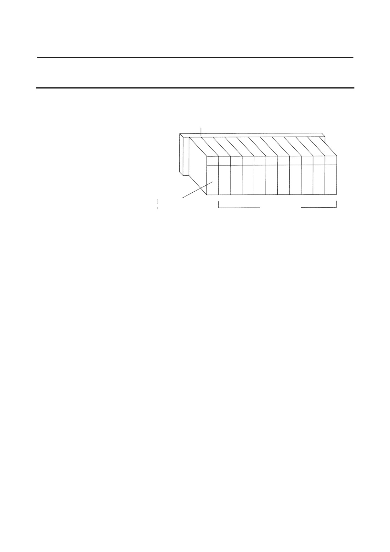
I/O Unit-A CONFIGURATION
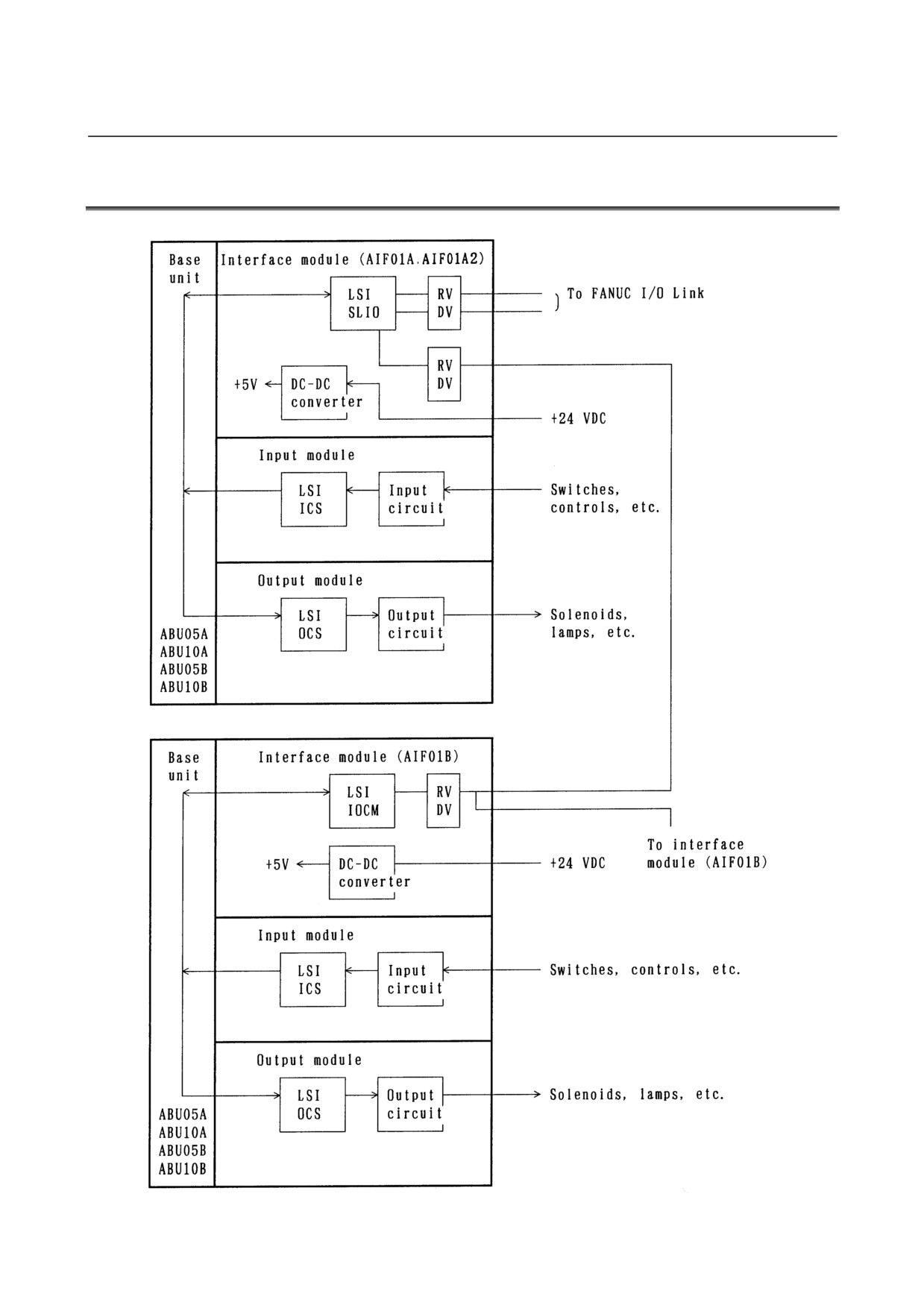
An I/O Unit-A consists of a base unit, interface module, and I/O
modules.
Base unit (ABU05A, ABU10A, ABU05B, or ABU10A)
Interface module
(AIF01A, AIF01A2,
I/O modules
AIF01B, or AIF02C)
- 209 -
1.OVERVIEW
MAINTENANCE
B-61813E/04
1.3
BLOCK DIAGRAM
- 210 -
B-61813E/04
MAINTENANCE
1.OVERVIEW
1.4
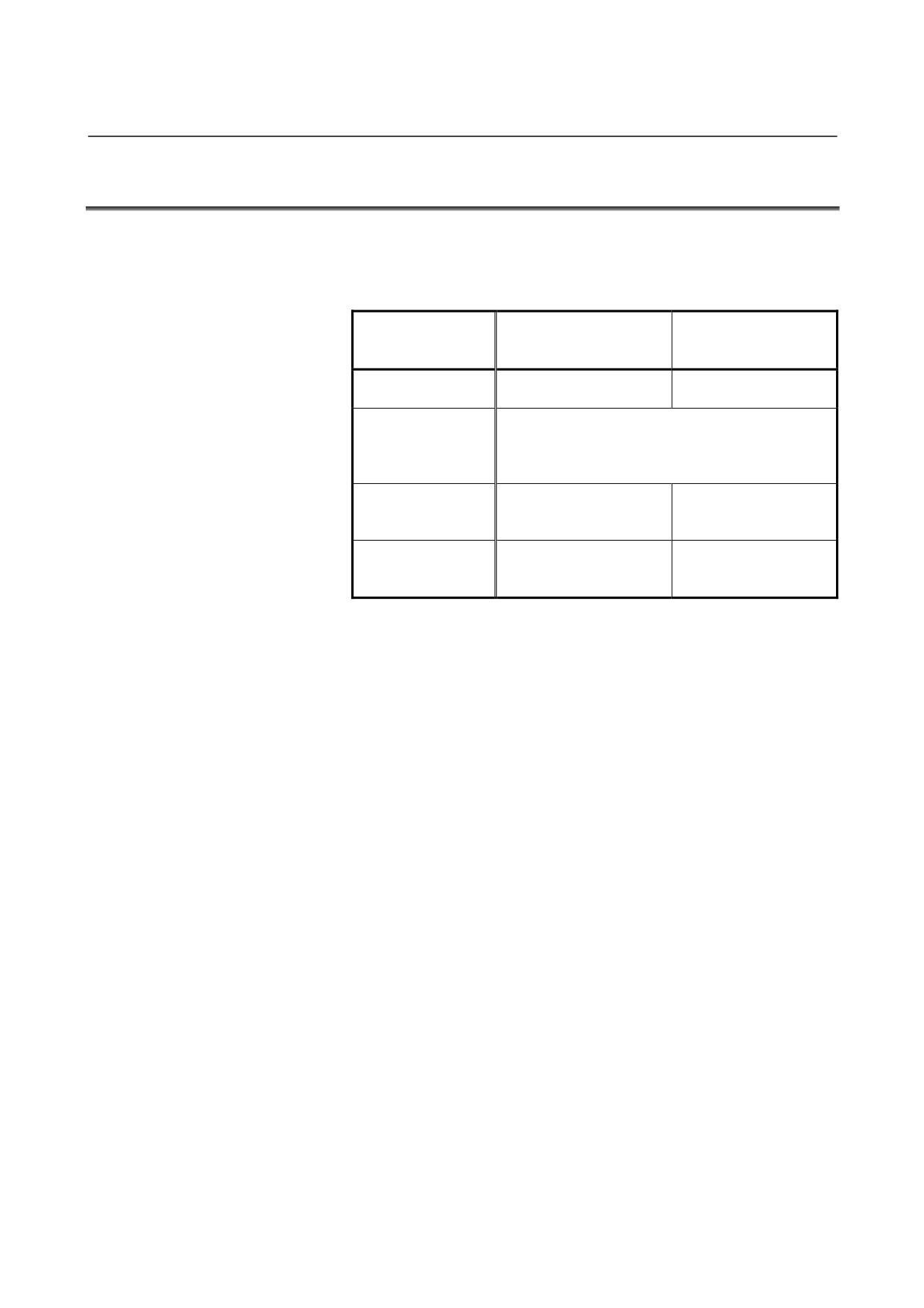
I/O Unit-MODEL A CONFORMING TO UL/C-UL
The units conforming to the UL/C-UL standard have different drawing
numbers.
The following table lists the units conforming to the UL/C-UL standard
and those not.
I/O Unit-MODEL A
I/O Unit-MODEL A not
conforming to the
conforming to the
UL/C-UL standard
UL/C-UL standard
Unit drawing
A03B-0819-Jxxx
A03B-0807-Jxxx
number
Unit specification
(interface,
Same specification
dimensions, and
weight)
Fire retardancy: 94V-0
Plastic case
(material less likely to
Fire retardancy: 94HB
burn)
The nameplates for the
The nameplates have
Unit nameplate
base unit and interface
no UL mark.
module bear a UL mark.
• Refer to Section 1.5, "LIST OF UNITS", in Part II for individual
unit drawings.
• It is possible to use units conforming to the UL/C-UL standard and
those not conforming together.
- 211 -
1.OVERVIEW
MAINTENANCE
B-61813E/04
1.5
LIST OF UNITS
1.5.1
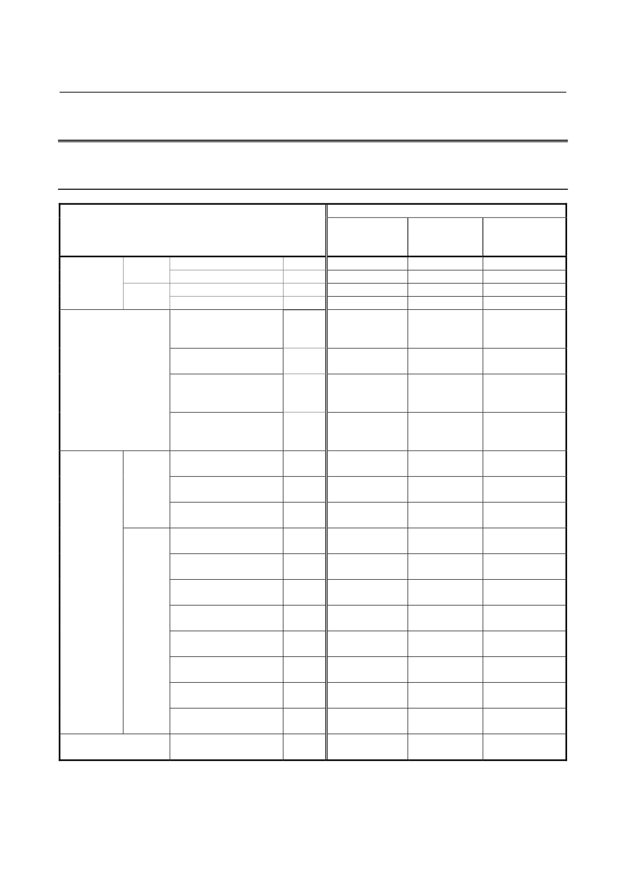
Units Conforming to UL/C-UL Standard: Ordering Information
A03B-0819-Jxxx
Unit conforming to UL/C-UL standard
Drawing number for
Name
Ordering
Unit drawing
printed circuit
information
number
board in unit
Base unit
10 slots
Horizontal type
ABU10A
A03B-0819-J001
A03B-0819-C001
A20B-9001-0040
Vertical type
ABU10B
A03B-0819-J004
A03B-0819-C004
A20B-2003-0100
5 slots
Horizontal type
ABU05A
A03B-0819-J002
A03B-0819-C002
A20B-9001-0020
Vertical type
ABU05B
A03B-0819-J003
A03B-0819-C003
A20B-2000-0510
Interface module
Power supply connector:
AIF01A
A03B-0819-J011
A03B-0819-C011
A20B-8000-0410
SORIAU JAPAN 3-pin
(former Burndy)
Power supply connector:
AIF01A2
A03B-0819-J014
A03B-0819-C014
A20B-8000-0411
Tyco Electronics 3-pin
Power supply connector:
AIF01B
A03B-0819-J012
A03B-0819-C012
A20B-8000-0420
SORIAU JAPAN 3-pin
(former Burndy)
Power supply connector:
AIF02C
A03B-0819-J013
A03B-0819-C013
A20B-8000-0710
SORIAU JAPAN 3-pin
(former Burndy)
DC input
Non-insulat
32 points, 20ms, HONDA
AID32A1
A03B-0819-J101
A03B-0819-C101
A20B-8002-0450
module
ions
50-pin
or -9000-0970
32 points, 2ms, HONDA
AID32B1
A03B-0819-J102
A03B-0819-C102
A20B-8002-0451
50-pin
or -9000-0971
32 points, 20 ms and 2 ms
AID32H1
A03B-0819-J111
A03B-0819-C111
A20B-8002-0452
intermixed, HONDA 50-pin
or -9000-0972
Insulations
16 points, NEG, 20ms,
AID16C
A03B-0819-J103
A03B-0819-C103
A20B-8002-0380
terminal block
or -9000-0931
16 points, NEG, 2ms, terminal
AID16K
A03B-0819-J113
A03B-0819-C113
A20B-8002-0381
block
or -9000-0932
16 points, POS, 20ms,
AID16D
A03B-0819-J104
A03B-0819-C104
A20B-8002-0370
terminal block
or -9000-0901
16 points, POS, 2ms, terminal
AID16L
A03B-0819-J114
A03B-0819-C114
A20B-8002-0371
block
or -9000-0902
32 points, 20ms, HONDA
AID32E1
A03B-0819-J105
A03B-0819-C105
A20B-8002-0150
50-pin
32 points, 20ms, HIROSE
AID32E2
A03B-0819-J110
A03B-0819-C110
A20B-8002-0160
50-pin
32 points, 2ms, HONDA
AID32F1
A03B-0819-J106
A03B-0819-C106
A20B-8002-0151
50-pin
32 points, 2ms, HIROSE
AID32F2
A03B-0819-J109
A03B-0819-C109
A20B-8002-0161
50-pin
AC input module
16 points, 100 to 115VAC
AIA16G
A03B-0819-J107
A03B-0819-C107
A20B-8000-0341
terminal block
- 212 -
B-61813E/04
MAINTENANCE
1.OVERVIEW
Unit conforming to UL/C-UL standard
Drawing number for
Name
Ordering
Unit drawing
printed circuit
information
number
board in unit
DC output
Non-insulat
32 points, NEG, 0.3A
AOD32A1
A03B-0819-J162
A03B-0819-C162
A20B-8002-0460
module
ions
HONDA 50-pin
or -9001-0110
Insulations
8 points, NEG, 2A, terminal
AOD08C
A03B-0819-J151
A03B-0819-C151
A20B-8002-0420
block
or -9001-0210
8 points, POS, 2A, terminal
AOD08D
A03B-0819-J152
A03B-0819-C152
A20B-8002-0410
block
or -9001-0220
8 points, POS, 2A, output
AOD08DP
A03B-0819-J183
A03B-0819-C183
A20B-8002-0060
protection, terminal block
16 points, NEG, 0.5A,
AOD16C
A03B-0819-J153
A03B-0819-C153
A20B-8002-0400
terminal block
or -9000-0941
16 points, POS, 0.5A,
AOD16D
A03B-0819-J154
A03B-0819-C154
A20B-8002-0390
terminal block
or -9000-0921
16 points, POS, 2A HONDA
AOD16D2
A03B-0819-J171
A03B-0819-C171
A20B-8002-0570
40-pin
16 points, POS, 2A
AOD16D3
A03B-0819-J185
A03B-0819-C185
A20B-8002-0520
Weidmüller 24-pin connector
16 points, POS, 0.3A, output
AOD16DP
A03B-0819-J182
A03B-0819-C182
A20B-8002-0070
protection, terminal block
32 points, NEG, 0.3A
AOD32C1
A03B-0819-J155
A03B-0819-C155
A20B-8002-0430
HONDA 50-pin connector
or -9001-0070
32 points, NEG, 0.3A
AOD32C2
A03B-0819-J172
A03B-0819-C172
A20B-8002-0440
HIROSE 50-pin connector
or -9001-0530
32 points, POS, 0.3A
AOD32D1
A03B-0819-J156
A03B-0819-C156
A20B-8000-0440
HONDA 50-pin connector
32 points, POS, 0.3A
AOD32D2
A03B-0819-J167
A03B-0819-C167
A20B-8000-0510
HIROSE 50-pin connector
AC output module
5 points, 2A, 100 to 230VAC
AOA05E
A03B-0819-J157
A03B-0819-C157
A20B-8000-0470
terminal block
8 points, 1A, 100 to 230VAC
AOA08E
A03B-0819-J158
A03B-0819-C158
A20B-8000-0480
terminal block
12 points, 0.5A, 100 to
AOA12F
A03B-0819-J159
A03B-0819-C159
A20B-8000-0321
115VAC, terminal block
Relay output module
8 points, 4A, terminal block
AOR08G
A03B-0819-J160
A03B-0819-C160
A20B-8002-0470
or -9001-0200
16 points, 2A, terminal block
AOR16G
A03B-0819-J161
A03B-0819-C161
A20B-8000-0101
16 points, 2A, HIROSE 50-pin
AOR16H2
A03B-0819-J165
A03B-0819-C165
A20B-8000-0500
DC input/output hybrid
DI: 24 points
AIO40A
A03B-0819-J200
A03B-0819-C200
A20B-9001-0240
module
DO: 16 points, NEG
HONDA 50-pin
Analog input module
12bit, terminal block
AAD04A
A03B-0819-J051
A03B-0819-C051
A20B-8000-0450
16bit, terminal block
AAD04B
A03B-0819-J063
A03B-0819-C063
A20B-8002-0590
Analog output module
12bit, terminal block
ADA02A
A03B-0819-J052
A03B-0819-C052
A20B-8000-0460
14bit, terminal block
ADA02B
A03B-0819-J060
A03B-0819-C060
A20B-8001-0980
High-speed counter module
ACT01A
A03B-0819-J053
A03B-0819-C053
A20B-8000-0540
Temperature input module
Pt/JPt
ATI04A
A03B-0819-J056
A03B-0819-C056
A74L-0001-0083#PT
J/K
ATI04B
A03B-0819-J057
A03B-0819-C057
A74L-0001-0083#JK
Pt/JPt
ATB01A
A03B-0819-J350
A03B-0819-C350
A20B-1005-0920
J/K
ATB01B
A03B-0819-J351
A03B-0819-C351
A20B-1005-0930
- 213 -
1.OVERVIEW
MAINTENANCE
B-61813E/04
1.5.2
Other Units (not Conforming to UL/C-UL)
Ordering
Drawing number
Name
information
for printed circuit
Optical I/O Link adapter
A13B-0154-B001
A20B-1004-0240
High-speed response type optical I/O Link
A13B-0154-B002
A20B-1004-0241
adapter
Optical fiber junction adapter
A02B-0094-K841
-
I/O Link dummy unit
A13B-0167-B001
A20B-8000-0940
2-channel I/O Link connector adapter
A20B-1007-0680
A20B-1007-0680
3-channel I/O Link connector adapter
A20B-1008-0360
A20B-1008-0360
1.5.3
Early Units (Units not Conforming to UL/C-UL: Ordering
Information A03B-0807-Jxxx)
The modules listed below are those produced before the factory was
UL-approved.
The module's basic performance does not differ between
A03B-0807-Jxxx and A03B-0819-Jxxx.
The units with the new ordering information A03B-0819-Jxxx are
housed in cases made of material less likely to burn.
Early unit
Drawing number
Name
Early ordering
Early-unit drawing
for printed circuit
information
number
board in early unit
Base unit
10 slots
Horizontal type
ABU10A
A03B-0807-J001
A03B-0807-C001
A20B-9001-0040
A20B-2003-0100
Vertical type
ABU10B
A03B-0807-J004
A03B-0807-C004
or -2000-0550
5 slots
Horizontal type
ABU05A
A03B-0807-J002
A03B-0807-C002
A20B-9001-0020
Vertical type
ABU05B
A03B-0807-J003
A03B-0807-C003
A20B-2000-0510
Interface module
AIF01A
A03B-0807-J011
A03B-0807-C011
A20B-8000-0410
AIF01B
A03B-0807-J012
A03B-0807-C012
A20B-8000-0420
AIF02C
A03B-0807-J013
A03B-0807-C013
A20B-8000-0710
32 points, 20ms, HONDA
DC input
Non-insulations
AID32A1
A03B-0807-J101
A03B-0807-C101
A20B-9000-0970
50-pin
module
32 points, 2ms, HONDA
AID32B1
A03B-0807-J102
A03B-0807-C102
A20B-9000-0971
50-pin
32 points, 20 ms and 2 ms
AID32H1
A03B-0807-J111
A03B-0807-C111
A20B-9000-0972
intermixed, HONDA 50-pin
16 points, NEG, 20ms,
Insulations
AID16C
A03B-0807-J103
A03B-0807-C103
A20B-9000-0931
terminal block
16 points, NEG, 2ms,
AID16K
A03B-0807-J113
A03B-0807-C113
A20B-9000-0932
terminal block
16 points, POS, 20ms,
AID16D
A03B-0807-J104
A03B-0807-C104
A20B-9000-0901
terminal block
16 points, POS, 2ms,
AID16L
A03B-0807-J114
A03B-0807-C114
A20B-9000-0902
terminal block
32 points, 20ms, HONDA
A20B-8002-0150
AID32E1
A03B-0807-J105
A03B-0807-C105
50-pin
or -9001-0010
32 points, 20ms, HIROSE
A20B-8002-0160
AID32E2
A03B-0807-J110
A03B-0807-C110
50-pin
or -9001-0280
32 points, 2ms, HONDA
A20B-8002-0151
AID32F1
A03B-0807-J106
A03B-0807-C106
50-pin
or -9001-0011
32 points, 2ms, HIROSE
A20B-8002-0161
AID32F2
A03B-0807-J109
A03B-0807-C109
50-pin
or -9001-0281
16 points, 100 to 115VAC
AC input module
AIA16G
A03B-0807-J107
A03B-0807-C107
A20B-8000-0341
terminal block
- 214 -
B-61813E/04
MAINTENANCE
1.OVERVIEW
Early unit
Drawing number
Name
Early ordering
Early-unit drawing
for printed circuit
information
number
board in early unit
32 points, NEG, 0.3A,
DC output
Non-insulations
AOD32A1
A03B-0807-J162
A03B-0807-C162
A20B-9001-0110
HONDA 50-pin
module
8 points, NEG, 2A, terminal
Insulations
AOD08C
A03B-0807-J151
A03B-0807-C151
A20B-9001-0210
block
or -9000-0951
8 points, POS, 2A, terminal
AOD08D
A03B-0807-J152
A03B-0807-C152
A20B-9001-0220
block
or -9000-0911
16 points, NEG, 0.5A,
AOD16C
A03B-0807-J153
A03B-0807-C153
A20B-9000-0941
terminal block
16 points, POS, 0.5A,
AOD16D
A03B-0807-J154
A03B-0807-C154
A20B-9000-0921
terminal block
16 points, POS, 2A, HIROSE
AOD16D2
A03B-0807-J171
A03B-0807-C171
A20B-8002-0570
40-pin
or -9001-0490
16 points, POS, 0.3A, output
AOD16DP
A03B-0807-J182
A03B-0807-C182
A20B-8002-0070
protection, terminal block
32 points, NEG, 0.3A,
AOD32C1
A03B-0807-J155
A03B-0807-C155
A20B-9001-0070
HONDA 50-pin
32 points, NEG, 0.3A,
AOD32C2
A03B-0807-J172
A03B-0807-C172
A20B-9001-0530
HIROSE 50-pin
32 points, POS, 0.3A,
AOD32D1
A03B-0807-J156
A03B-0807-C156
A20B-8000-0440
HONDA 50-pin
32 points, POS, 0.3A,
AOD32D2
A03B-0807-J167
A03B-0807-C167
A20B-8000-0510
HIROSE 50-pin
5 points, 2A, 100 to 230VAC
A20B-8000-0470
AC output module
AOA05E
A03B-0807-J157
A03B-0807-C157
terminal block
or -8000-0251
8 points, 1A, 100 to 230VAC
A20B-8000-0480
AOA08E
A03B-0807-J158
A03B-0807-C158
terminal block
or -8000-0381
12 points, 0.5A, 100 to
AOA12F
A03B-0807-J159
A03B-0807-C159
A20B-8000-0321
115VAC
terminal block
Relay output module
8 points, 4A, terminal block
AOR08G
A03B-0807-J160
A03B-0807-C160
A20B-9001-0200
or -9000-0961
16 points, 2A, terminal block
AOR16G
A03B-0807-J161
A03B-0807-C161
A20B-8000-0101
16 points, 2A, HIROSE
AOR16H2
A03B-0807-J165
A03B-0807-C165
A20B-8000-0500
50-pin
Analog input module
12bit, terminal block
AAD04A
A03B-0807-J051
A03B-0807-C051
A20B-8000-0450
Analog output module
12bit, terminal block
ADA02A
A03B-0807-J052
A03B-0807-C052
A20B-8000-0460
14bit, terminal block
ADA02B
A03B-0807-J060
A03B-0807-C060
A20B-8001-0980
High-speed counter module
ACT01A
A03B-0807-J053
A03B-0807-C053
A20B-8000-0540
Temperature input module
Pt/JPt
ATI04A
A03B-0807-J056
A03B-0807-C056
A74L-0001-0083#PT
J/K
ATI04B
A03B-0807-J057
A03B-0807-C057
A74L-0001-0083#JK
Pt/JPt
ATB01A
A03B-0807-J350
A03B-0807-C350
A20B-1005-0920
J/K
ATB01B
A03B-0807-J351
A03B-0807-C351
A20B-1005-0930
- 215 -