FANUC I/O Unit-MODEL A. CONNECTION AND MAINTENANCE MANUAL (B-61813E/04) - page 8
B-61813E/04
MAINTENANCE
2.INDICATION
2.1
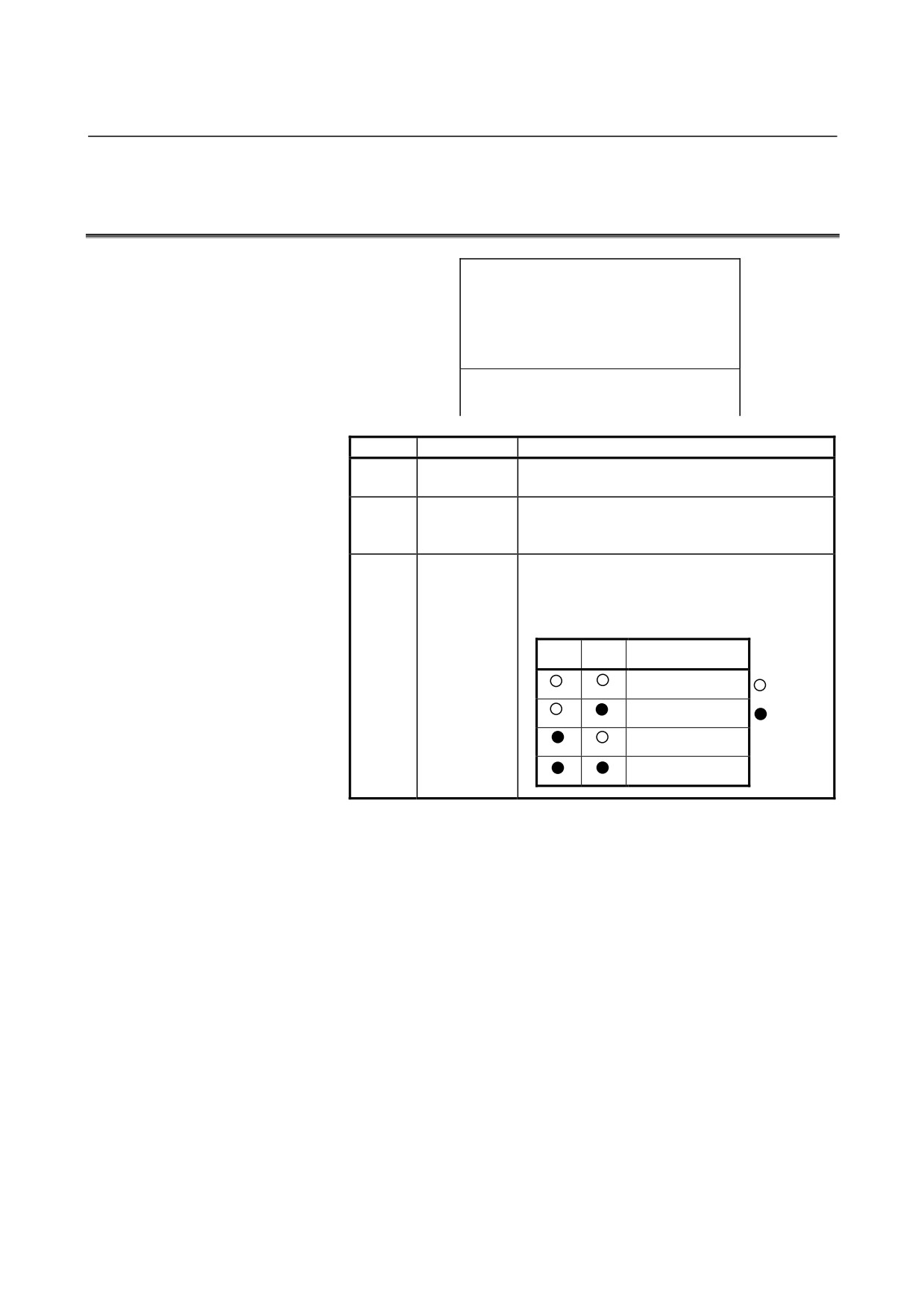
INTERFACE MODULE (AIF01A, AIF01A2) LED
INDICATORS
{ PWR
{ LINK
{ BA1
{ BA0
A I F 0 1 A
Marking
Name
Description
PWR
Power-on
On: The interface module is supplied with power of
24 VDC.
LINK
Link
On: The I/O Link is operating properly.
Normally, this LED lights several to ten-odd
seconds after the master is turned on.
BA1
Base address
These LEDs indicate which base unit the inter-face
BA0
module is transferring data with. If a failure occurs
(the LINK LED is turned on, then off), BA0 or BA1,
whichever is operating, is turned on.
BA1
BA0
Base number
Base #0
: Off
Base #1
: On
Base #2
Base #3
Failures, their causes, and required actions
(1) PWR is off.
c
Power (24 VDC) is not supplied or the supply voltage is
abnormal.
⇒ Supply power of 24 VDC ± 10%.
d A The fuse in the interface module has blown.
⇒ Eliminate the cause that made the fuse to blow, then
replace the fuse with a spare. (See Chapter 3.) The
following may cause the fuse to blow:
•
A sum of power requirements for all input modules
exceeds the rating. (Refer to Section 4.4 in Part I.)
•
A voltage of +24 VDC, supplied from input module
AID32A1, AID32B1 or AID32H1 to the outside, is
short-circuited to the cabinet or the like.
•
The interface module or any of the I/O modules is
defective.
- 217 -
2.INDICATION
MAINTENANCE
B-61813E/04
e
An I/O module is defective.
⇒ Remove the I/O modules sequentially to pinpoint the
defective one. Then, replace it with a spare.
f
An interface module is defective.
⇒ Replace it with a spare.
(2)
LINK has never been turned on since power is supplied.
c
If PWR is off, go to item 1).
d
The attempted power turn-on sequence was incorrect.
⇒ The slaves (I/O Unit-A, Power Mate, Series 0, etc.)
must be supplied with power at the same time or before
the master (CNC or F-D Mate) is supplied with power.
(Refer to Section 4.2 in Part I.)
If an attempt is made to supply power to a slave on an
interface module after the master is turned on, LINK on
the interface module is not turned on provided that the
interface module corresponds to that slave or to any
slave ahead of that slave (one on the far side with
respect to the master).
e
I/O Link cables are broken or short-circuited.
⇒ With reference to Note below, check the cables, and
take an appropriate action.
f
Any device on the I/O Link is defective.
⇒ With reference to Note below, find a defective device,
and take an appropriate action. If an I/O Unit seems to
be defective, replace interface module with a spare.
NOTE
How to pinpoint a failure in the I/O Link in event of
items d to f .
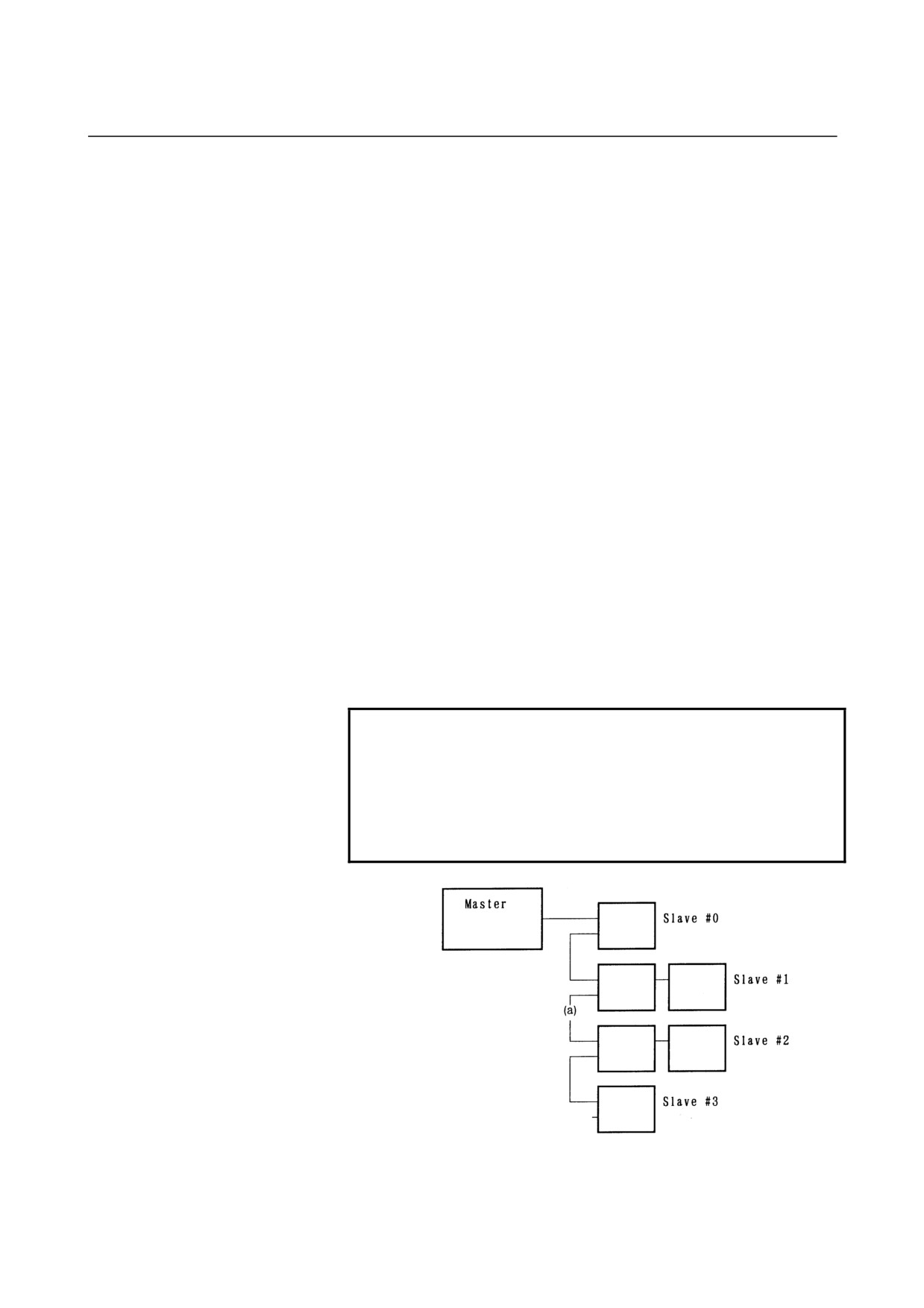
Check the LEDs on the master to find out which group
contains slaves whose I/O Link is established with the
master. (Refer to the maintenance manual for the
master.)
- 218 -
B-61813E/04
MAINTENANCE
2.INDICATION
For example, if the master is linked to slaves (slave #0
and #1) that belong to separate groups, the timing of
turning on slave #2 is bad, the cable is broken or
short-circuited at point (a), slave #2 is defective.
If the master is not linked to any slave, the master may
be defective.
(3)
LINK is turned on once, then off.
c
One of the devices on the I/O Link is turned off.
⇒ Turn off all devices, then turn them on.
d The DI/DO assignment for the master is invalid.
⇒ When I/O Unit bases 1 to 3 (units under control of
interface module AIF01B) are not connected, if DI/DO
units are assigned to these bases, LINK is turned on, but
turned off immediately.
Correct the DI/DO assignment.
e
The I/O Link cable is broken or short-circuited.
⇒ Check the cable, and take an appropriate action.
f
Any device on the I/O Link is defective.
⇒ With reference to the maintenance manual for the
master, find a defective device, and take an appropriate
action. If an I/O Unit seems defective, replace the
interface module
(AIF01A, AIF01A2, or AIF01B)
installed in the base unit indicated by BA1 or BA0.
- 219 -
2.INDICATION
MAINTENANCE
B-61813E/04
2.2
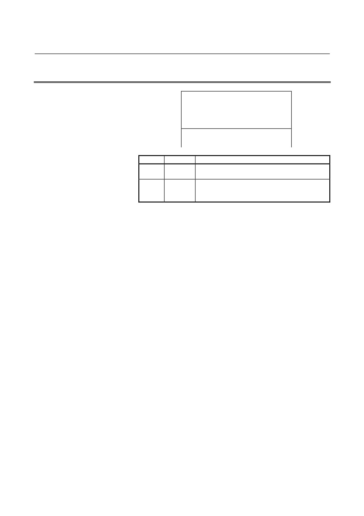
INTERFACE MODULE (AIF01B) LED INDICATORS
{ PWR
{ LINK
A I F 0 1 B
Marking
Name
Description
PWR
Power-on
On: The interface module is supplied with power of 24
VDC.
LINK
Link
On: The I/O Link is operating properly.
Normally, this LED lights several to ten-odd seconds
after the master is turned on.
Failures, their causes, and required actions
(1)
PWR is off.
c
Power (24 VDC) is not supplied or the supply voltage is
abnormal.
⇒ Supply power of 24 VDC ±10%.
d The fuse in the interface module has blown.
⇒ Eliminate the cause that made the fuse to blow, then
replace the fuse with a spare. (See Chapter 3.) The
following may cause the fuse to blow:
•
A sum of power requirements for all input modules
exceeds the rating. (Refer to Section 4.4 in Part I.)
•
A voltage of +24 VDC, supplied from input module
AID32A1, AID32B1 or AID32H1 to the outside, is
short-circuited to the cabinet or the like.
•
The interface module or any of the I/O modules is
defective.
e
An I/O module is defective.
⇒ Remove the I/O modules sequentially to pinpoint the
defective one. Then, replace it with a spare.
f
An interface module is defective.
⇒ Replace it with a spare.
(2)
LINK has never been turned on since power is supplied.
c
If PWR is off, go to item 1).
d
If LINK on the AIF01A or AIF01A2 in the same group is off,
go to Section 2.1.
e
The signal cable between I/O Units in the same group is
broken or short-circuited.
⇒ Check the cable, and take an appropriate action.
f
An interface module is defective.
⇒ Replace it with a spare.
(3)
LINK is turned on once, then turned off.
c
See section 2.1.
- 220 -
B-61813E/04
MAINTENANCE
2.INDICATION
2.3
INTERFACE MODULE (AIF02C) LED INDICATORS
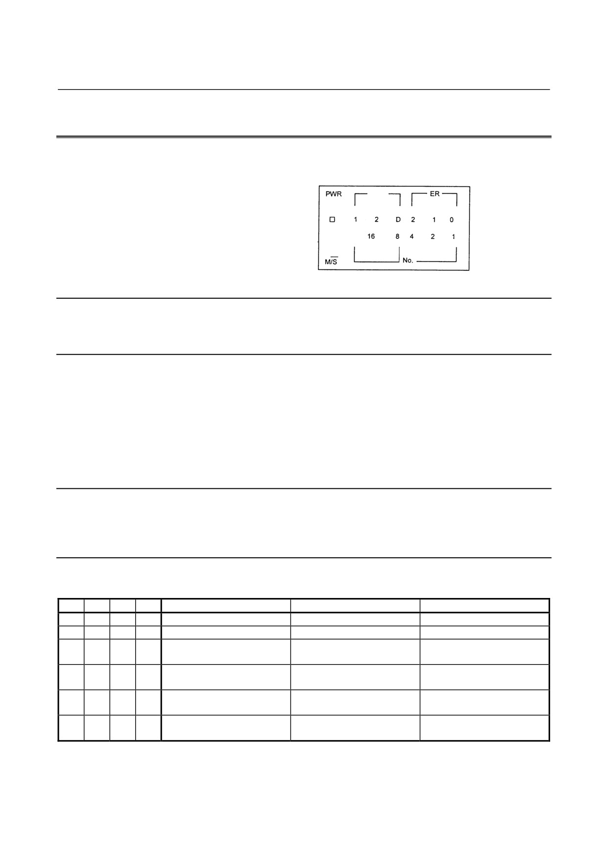
The LED indicator panel of the AIF02C is shown below. Each of its
components are described in the following paragraphs.
LNK
M
2.3.1
PWR Indicator
This LED lights when the power is switched on.
2.3.2
LNK Indicators
(1) LNK-1 : Lights when the I/O link for the I/O Unit-A is operating
normally.
(2) LNK-2 : Lights when the I/O link for the I/O Unit-B is operating
normally.
(3) LNK-D : Lights when the distributed link with the I/O Unit-B is
operating normally. (The indicator dims if only a few
base units are connected.)
2.3.3
ER Indicators
An ER indicator lights if an error occurs on the distributed link.
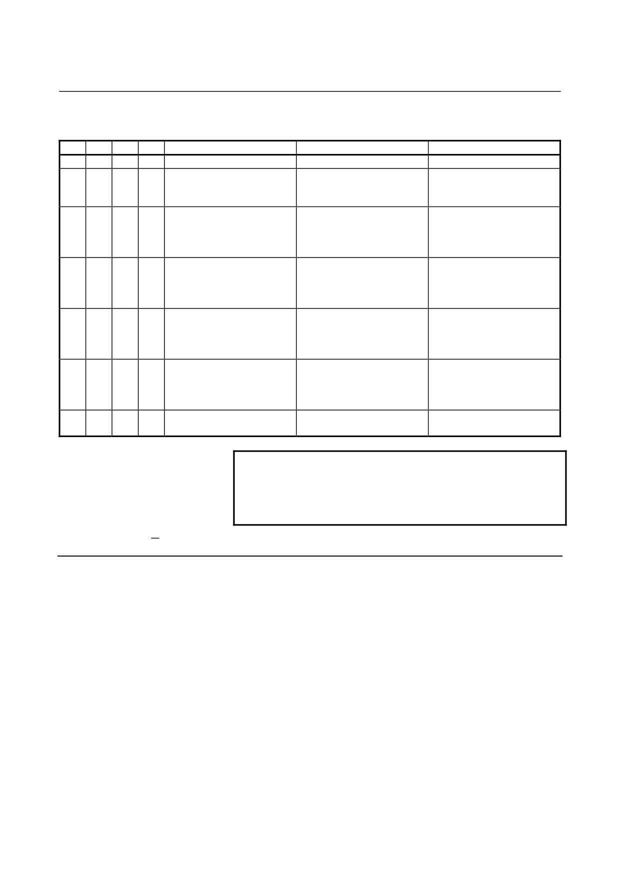
See the tables on the following page for details.
2.3.4
LED Indicators
(1) When the unit No. (1 to 16) is off (o-on and ×-off)
M/S
ER2
ER1
ER0
Error
Description
Major cause of error
{
×
×
{
Interface unit peripheral error
The interface unit is abnormal.
Interface unit failure
{
×
{
×
Interface unit RAM parity error
The interface unit is abnormal.
Interface unit failure
{
{
×
×
I/O link error reception
An error has occurred in a unit
Failure in a unit connected to
connected to the I/O link.
the I/O link
{
{
×
{
I/O link framing error
The I/O link communication
-
end signal is abnormal.
{
{
{
×
I/O link CRC error
I/O link communication data is
-
abnormal.
{
{
{
{
Interface unit watchdog timer
Communication from the I/O
-
error
link host has stopped.
- 221 -
2.INDICATION
MAINTENANCE
B-61813E/04
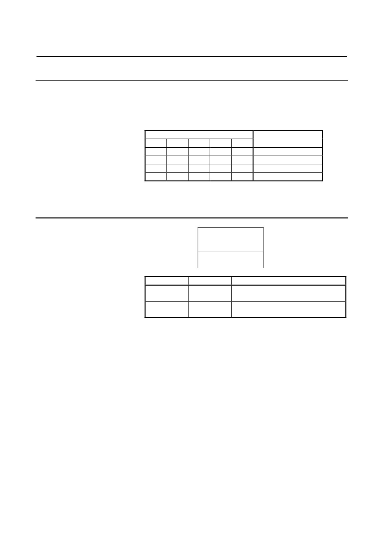
(2) When the unit No. (1 to 16) is on (o-on and ×-off)
M/S
ER2
ER1
ER0
Error
Description
Major cause of error
×
×
×
{
Basic unit peripheral error
The basic unit is abnormal.
Basic unit failure
{
×
{
×
Basic unit number error
A unit with an invalid unit
-
number has responded to the
interface unit.
×
×
{
{
Basic unit reception data count
The number of communication
Two or more units have the
error
bytes has exceeded four.
same unit number, or the unit of
interest is not provided with a
terminating resistor.
×{
{
×
×
Basic unit framing error
The communication end signal
Two or more units have the
(*1)
is abnormal.
same unit number, or the unit of
interest is not provided with a
terminating resistor.
×{
{
×
{
Basic unit DMI error
The communication waveform
Two or more units have the
(*1)
has been distorted.
same unit number, or the unit of
interest is not provided with a
terminating resistor.
×{
{
{
×
Basic unit CRC error
The communication data is
Two or more units have the
(*1)
abnormal.
same unit number, or the unit of
interest is not provided with a
terminating resistor.
×
{
{
{
Basic unit watchdog timer error
Communication with the
-
interface unit has stopped.
NOTE (*1)
If M/S lights, it means that the interface module
(AIF02C) detected the error.
If it does not light, it means that the basic unit of the
I/O Unit-B detected the error.
2.3.5
M/S Indicator
If an error occurs on a distributed link, the M/S indicator indicates
whether the error was detected in the interface module or basic error
side.
On: The error has been detected on the interface module side.
Off: The error has been detected on the basic unit side.
- 222 -
B-61813E/04
MAINTENANCE
2.INDICATION
2.3.6
No. Indicators
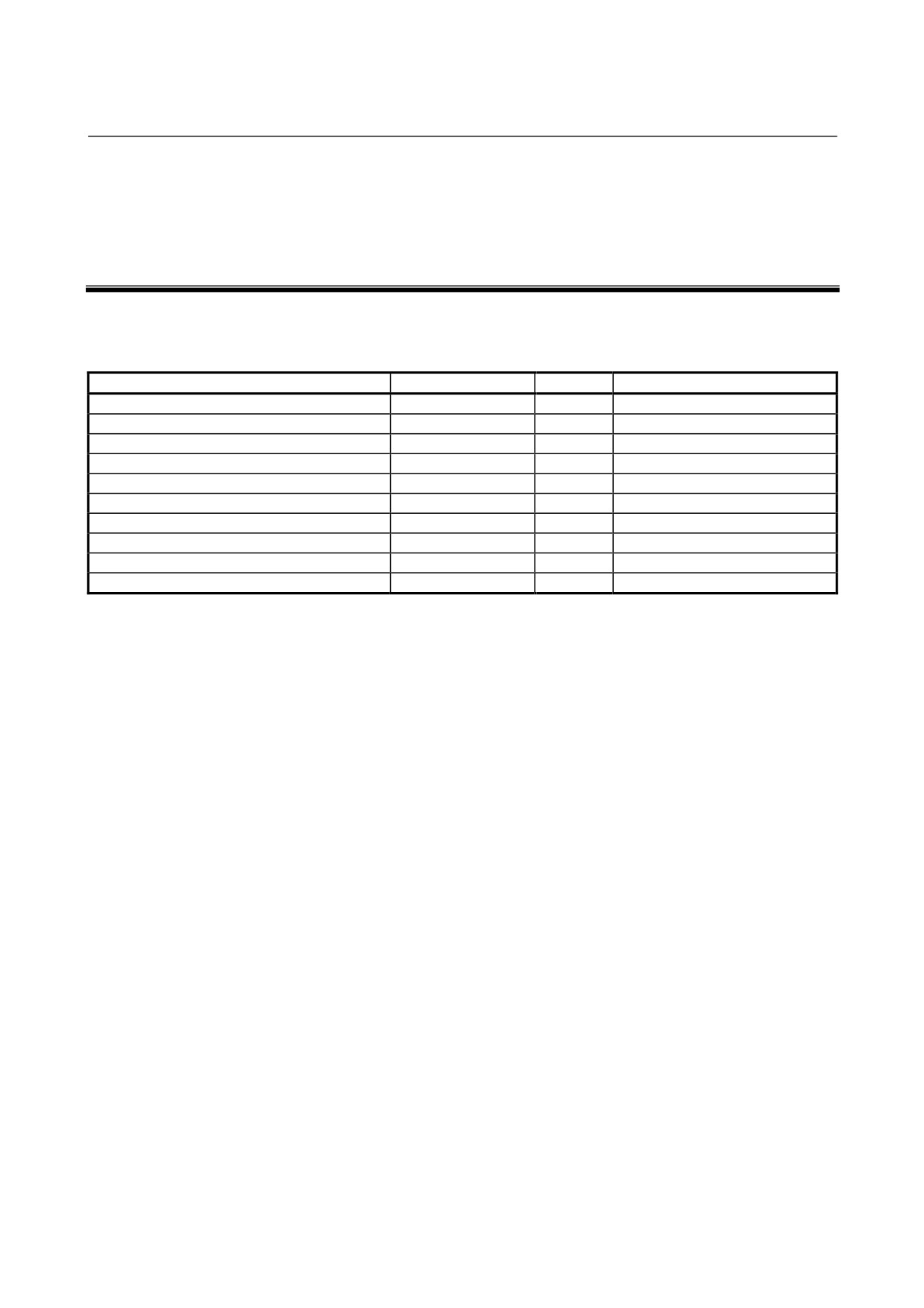
If an error occurs on a distributed link, the No. indicators indicate the
basic unit No. where the error is detected. The sum of the values for
which a lamp lights corresponds to the basic unit No.
Example)
No.
Unit No.
16
8
4
2
1
×
×
×
×
{
1
{ -On
×
×
{
×
{
5
×-Off
×
{
×
{
×
10
{
×
{
×
×
20
2.4
LED INDICATORS ON THE INPUT/OUTPUT MODULES
(HAVING 16 OR FEWER INPUT/OUTPUT POINTS)
A01234567
F
B01234567
Label
Name
Description
A0 to 7
Input/output
On : The corresponding input or output is on.
B0 to 7
indicator
F
Fuse alarm
On : A fuse incorporated in the output
module has blown.
- 223 -
3.FUSES
MAINTENANCE
B-61813E/04
3
FUSES
The modules listed below have built-in fuses. If a fuse blows, remove
the cause, then replace the fuse with a spare.
Module
Indication
Rating
Fuse specification
Interface module AIF01A
PWR is off
3.2A
A60L-0001-0290#LM32
Interface module AIF01A2
PWR is off
3.2A
A60L-0001-0290#LM32
Interface module AIF01B
PWR is off.
3.2A
A60L-0001-0290#LM32
Interface module AIF02C
PWR is off.
3.2A
A60L-0001-0290#LM32
Output module with 8 DC points AOD08C
F is on.
5A
A60L-0001-0260#5R00
Output module with 8 DC points AOD08D
F is on.
5A
A60L-0001-0260#5R00
Output module with 16 DC points AOD08D3
F is on.
5A
A60L-0001-0046#5.0
Output module with 5 AC points AOA05E
F is on.
3.15A
A60L-0001-0276#3.15
Output module with 8 AC points AOA08E
F is on.
3.15A
A60L-0001-0276#3.15
Output module with 12 AC points AOA12F
F is on.
3.15A
A60L-0001-0276#3.15
The fuses are on the PC boards in the modules.
- 224 -
4.REMOVING PC BOARDS
MAINTENANCE
B-61813E/04
4.1
HOW TO REMOVE TERMINAL BOARD-TYPE I/O MODULE
PC BOARDS
c
Remove the terminal board. (Refer to 4.5 in Part I.)
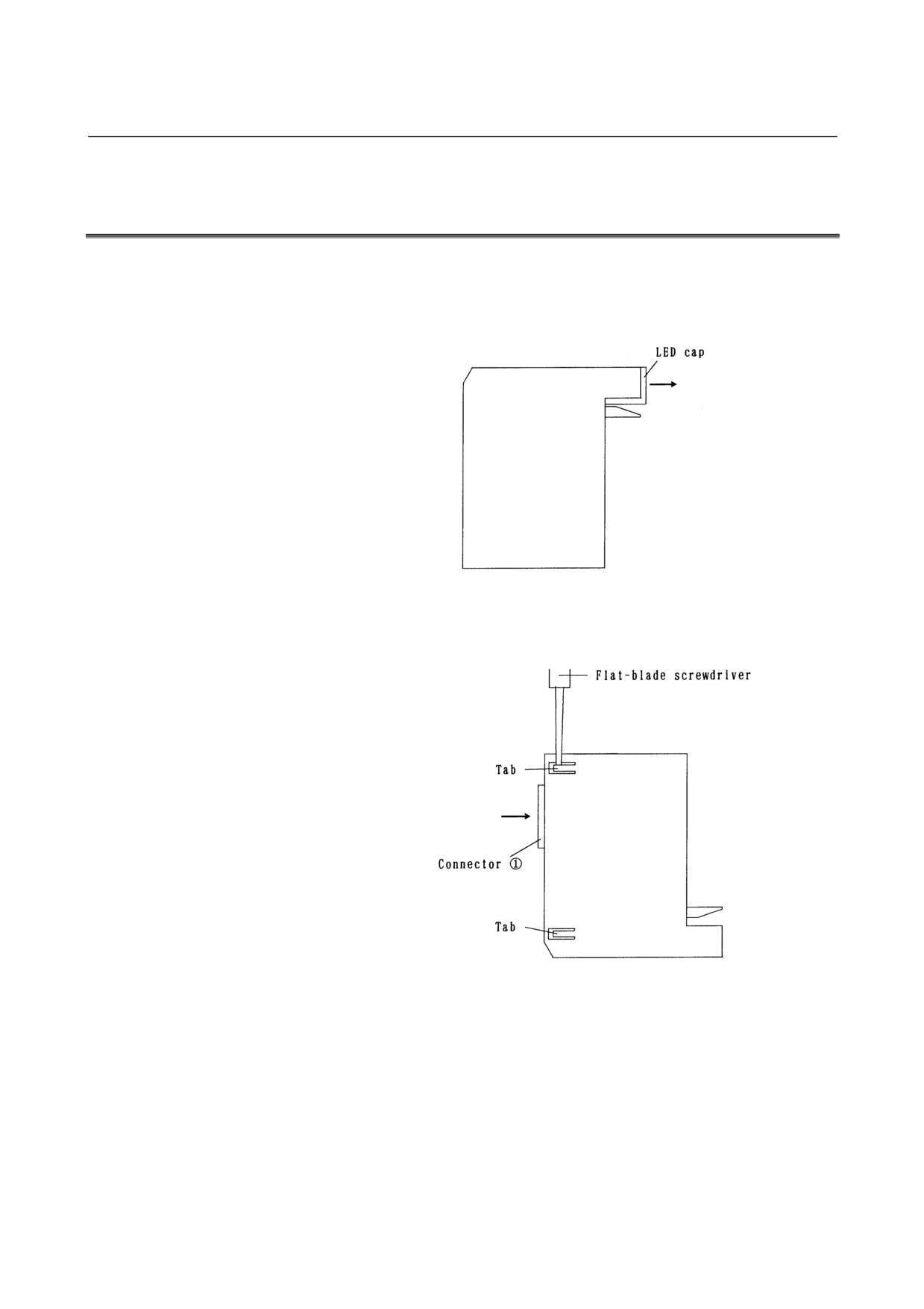
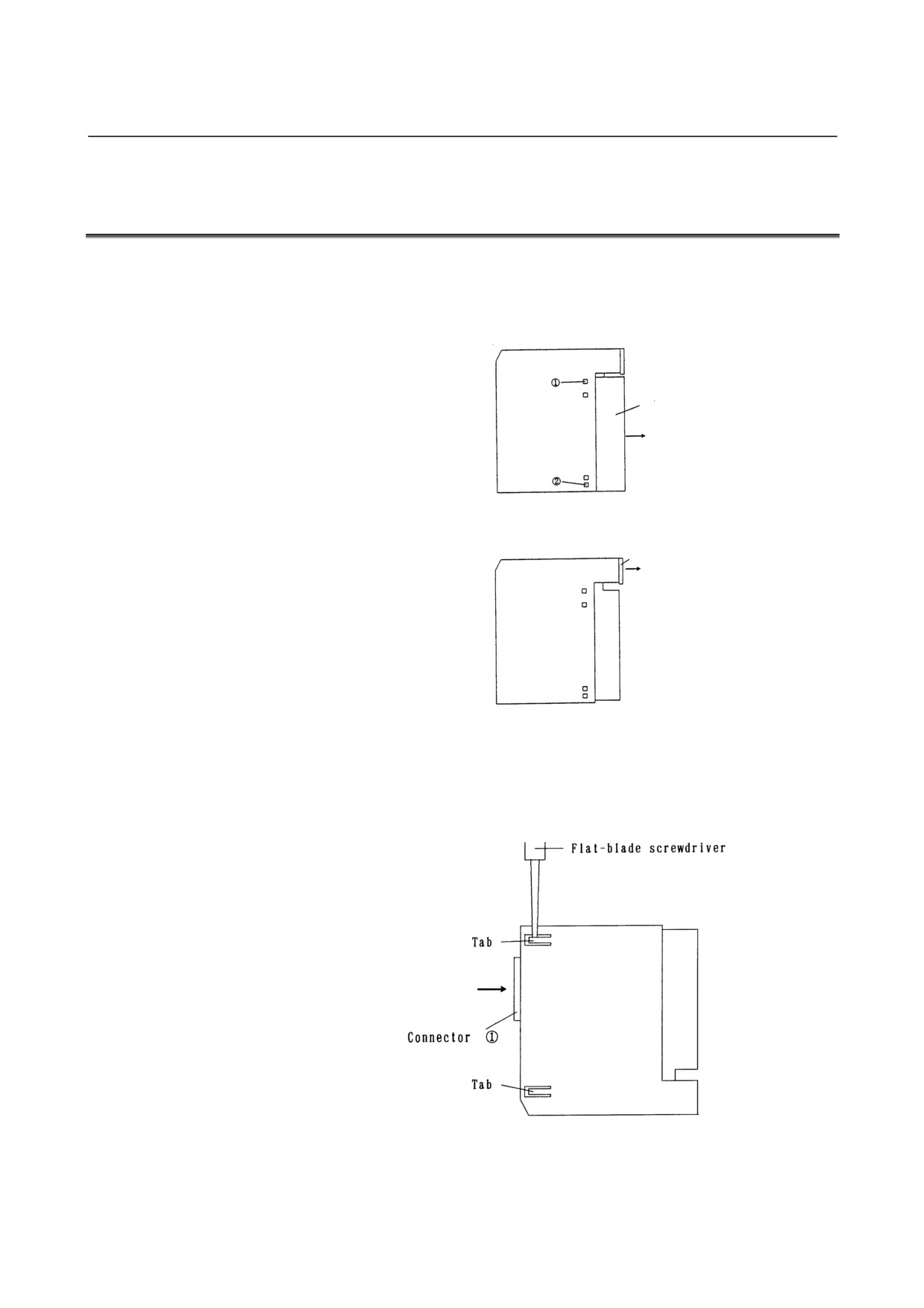
d Pull the LED cap in the direction of the arrow to remove it.
e
While pressing connector c in the direction of the arrow, raise the
tabs (two) on the module case with a flat-blade screwdriver.
- 226 -
B-61813E/04
MAINTENANCE
4.REMOVING PC BOARDS
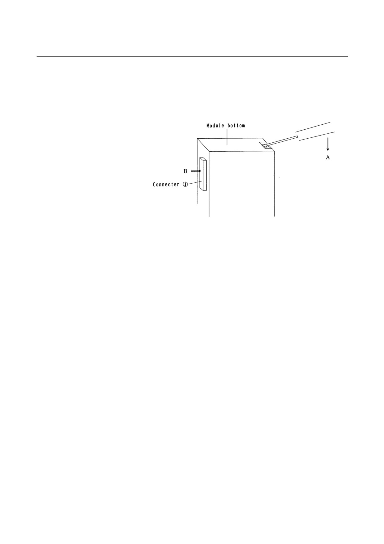
f
Put the tip of a flat-blade screwdriver into the gap between the
module case and terminal board connector, as shown below.
While pressing the screwdriver in the direction of arrow A, push
connector c in the direction of arrow B, and the PC board will
come out.
- 227 -
4.REMOVING PC BOARDS
MAINTENANCE
B-61813E/04
4.2
HOW TO REMOVE INTERFACE AND CONNECTOR-TYPE
I/O MODULE PC BOARDS
c
While pulling the cover in the direction of the arrow, press points
c and d
(on each side) with a flat-blade screwdriver to remove
the cover.
Cover
d Pull the LED cap in the direction of the arrow to remove it.
LED Cap
e
While pressing connector c in the direction of the arrow, raise the
tabs (two for a connector type I/O module and 4 for an interface
module) with a flat-screwdriver, then push connector c in the
direction of the arrow, and e PC board will come out.
- 228 -