FANUC R-30iB Plus CONTROLLER, iRVision 2D Camera Application. OPERATOR'S MANUAL - page 8
Know-How
2. CAMERA DATA SETTING
MEMO
Even in the case of a 6-axis robot, the target position may not always be set
automatically in cases where the motion range is small or the camera's field of
view is at a corner of the motion range. In this case, you can set the target
2
position by the same steps as a 4- or 5-axis robot.
2.3.8.2
4- or 5-axis robot
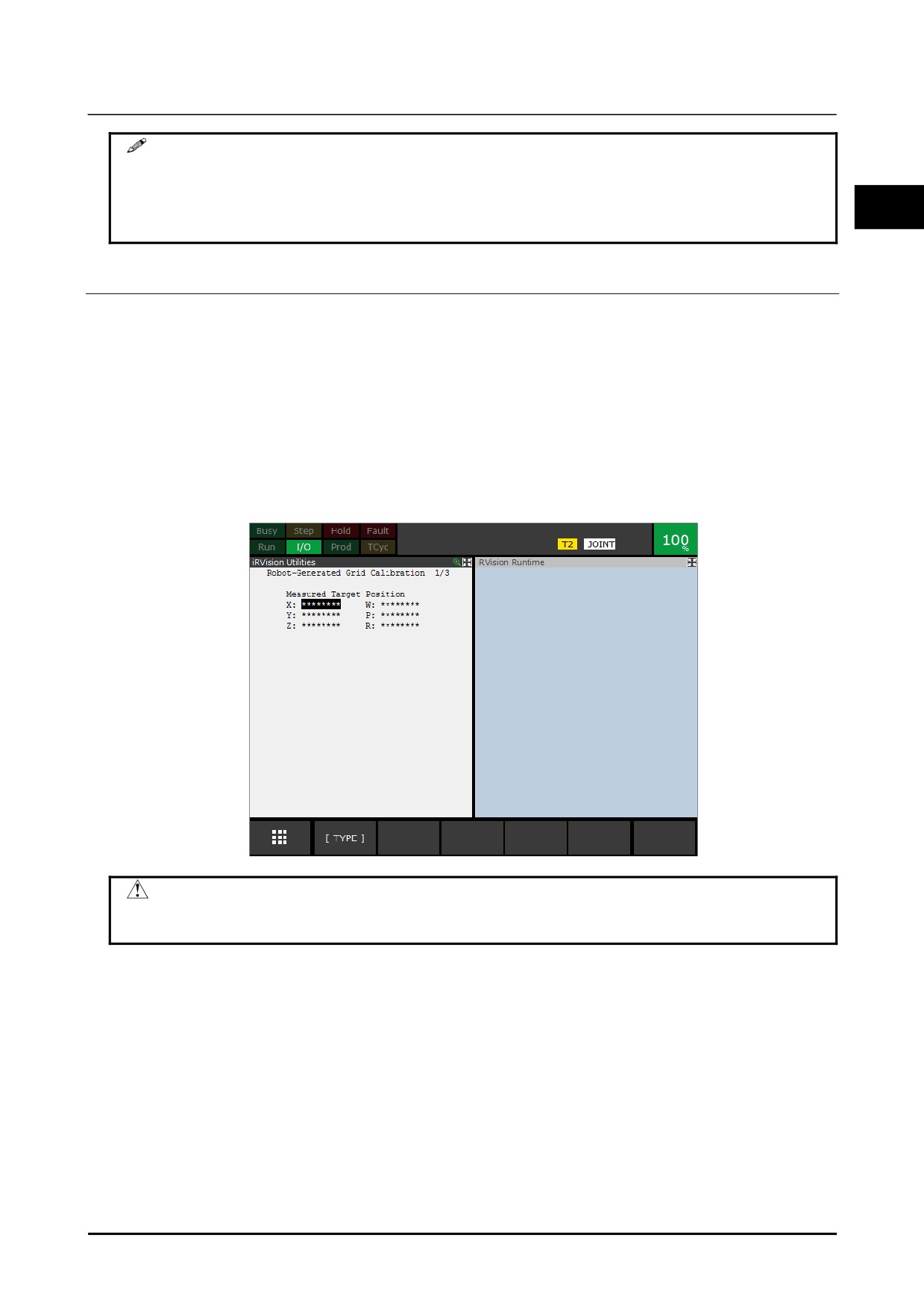
For a 4- or 5-axis robot, the target position cannot be set automatically. Set the target position using the
following procedure.
1
Place the cursor over [Target Position] on the robot-generated grid calibration main screen and press
F3 [POSITION].
A detailed screen of target position will appear.
2
Press F2 [DISP IMG] and display Vision Runtime.
3
From the drawing, calculate the frame values as seen from the robot's wrist flange, and enter it as the
target position.
Enter '0' for WPR.
CAUTION
The target position should correspond to the model origin trained in section 2.3.5.
If the positions are different, the camera cannot be calibrated properly.
B-83914EN-2/01
193
2. CAMERA DATA SETTING
Know-How
2.3.9
Generating Calibration Program
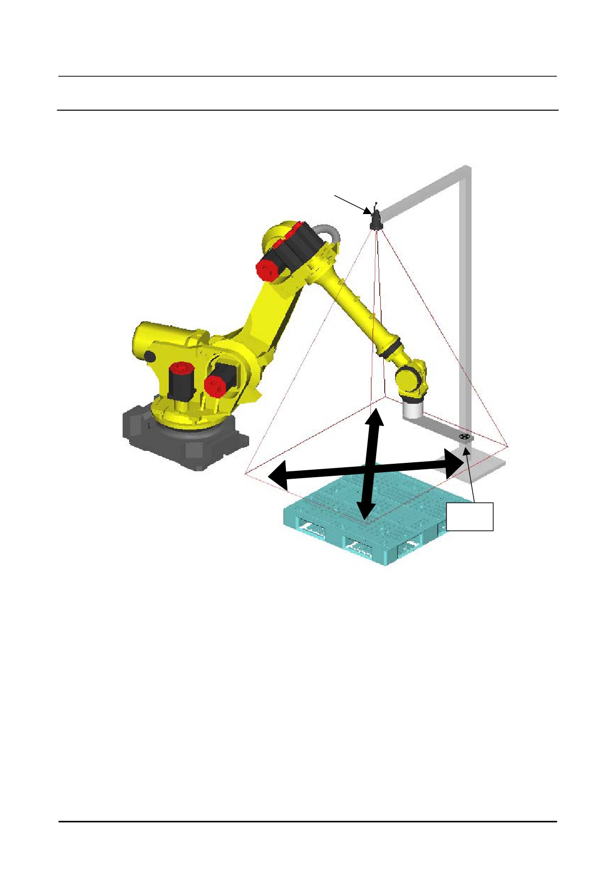
A robot measures the size of field of view while changes the target position as shown below, and
generates a robot program for camera calibration.
Camera
Target
Measurement of the size of a camera's field of view while changing the target position
194
B-83914EN-2/01
Know-How
2. CAMERA DATA SETTING
1
Refer to Know-how Edition Subsection 2.3.8, [Target Position Measurement] and check that the
status of the [Target Position] of the selected robot-generated grid calibration data is [Measured].
2
2
3
5
2
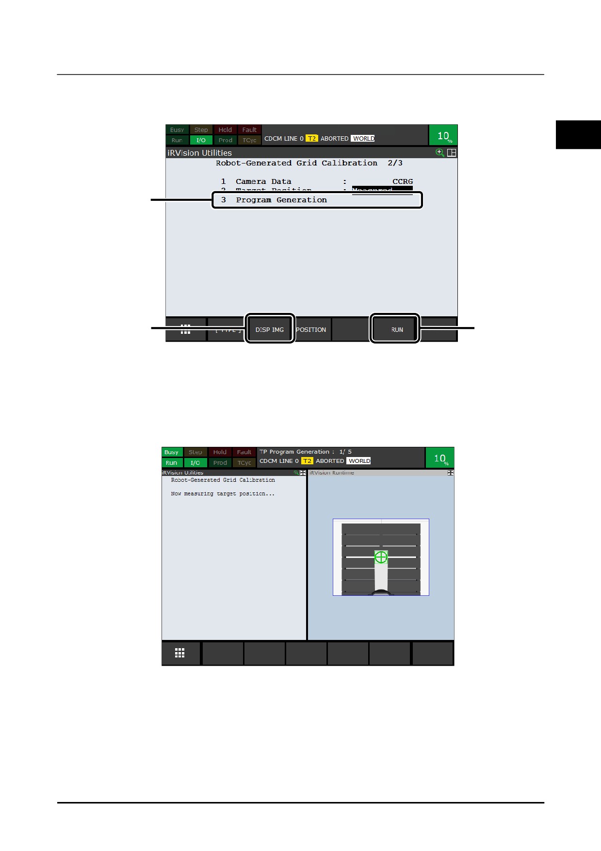
Place the cursor over [Program Generation].
3
Press F2 [DISP IMG] and display Vision Runtime Page.
4
Enable the teach pendant and clear the alarm.
5
While holding down the [SHIFT] key, press F5 [RUN].
Auto generation of a program will be executed.
Keep the [SHIFT] key held down during measurement.
6
When the measurement finishes, the robot will stop, and a message saying 'Measurement is
successfully' will be displayed on the screen.
7
Release the [SHIFT] key and click F4 [OK].
If the previous program generation was interrupted midway, a message saying [Are you sure to resume?]
will be displayed if you try to execute program generation. To resume from where it was interrupted,
press F4 [RESUME] while holding down the [SHIFT] key. If you want to start it over from the
beginning, press F5 [RESTART] while holding down the [SHIFT] key.
B-83914EN-2/01
195

2. CAMERA DATA SETTING
Know-How
CAUTION
Measurement cannot be executed if the target robot-generated grid calibration
setup screen is being displayed. Close the teaching screen. How
measurement is going can be checked using Vision Runtime.
The way to limit the target displacement range
In order to avoid the interference with peripheral equipment, you can limit the target displacement range.
1
Open the camera data edit screen, and click [Train Model] in the navigation.
2
Click the pattern match tool in the tree view.
3
Make the search window smaller to exclude sections where you do not want the robot to operate.
4
Click [SAVE] to save the changes.
5
Click [END EDIT] to close the edit screen.
6
Regenerate the program.
Calibration Program
The generated calibration program is like the one shown below.
All the robot positions in the calibration
program are taught in the joint format.
1:
UFRAME_NUM=2
2:
UTOOL_NUM=2
3:L P[1] 1000mm/sec FINE
4:
VISION CAMREA_CALIB 'CALIB1' REQUEST=1
5:L P[1001] 1000mm/sec FINE
6:
CALL IRVBKLSH(1)
7:
VISION CAMERA_CALIB 'CALIB1' REQUEST=1001
8:L P[1002] 1000mm/sec FINE
9:
CALL IRVBKLSH(1)
10: VISION CAMERA_CALIB 'CALIB1' REQUEST=1002
(Repeat as many times as the number of points)
293:L P[2048] 1000mm/sec FINE
294: CALL IRVBKLSH(1)
295: VISION CAMERA_CALIB 'CALIB1' REQUEST=2048
296:L P[2049] 1000mm/sec FINE
297: CALL IRVBKLSH(1)
298: VISION CAMERA_CALIB 'CALIB1' REQUEST=2049
299:L P[2] 1000mm/sec FINE
300: VISION CAMERA_CALIB 'CALIB1' REQUEST=2
The section of the program that finds an individual calibration program consists of the three lines shown
below. This set of three lines is repeated in the middle of the calibration program above.
5:L P[1001] 1000mm/sec FINE
6:
CALL IRVBKLSH(1)
7:
VISION CAMERA_CALIB 'CALIB1' REQUEST=1001
Each command in the program is briefly explained below.
4:
VISION CAMREA_CALIB 'CALIB1' REQUEST=1
196
B-83914EN-2/01
Know-How
2. CAMERA DATA SETTING
If you specify 1 in the request code of the CAMERA_CALIB command, all the calibration points in the
specified camera calibration are deleted. This is the first command to be executed in the calibration
program.
2
300: VISION CAMERA_CALIB 'CALIB1' REQUEST=2
If you specify 2 in the request code of the CAMERA_CALIB command, camera calibration data is
calculated using the found calibration points. This is the last command to be executed in the calibration
program.
7:
VISION CAMERA_CALIB 'CALIB1' REQUEST=1001
If you specify 1000 or a larger value in the request code of the CAMERA_CALIB command, the program
attempts to find a calibration point. The value specified in the request code is recorded as the index of
the calibration point, along with the found position.
In an automatically generated calibration program, 1000 to 1999 represent the calibration points on
calibration plane 1, and 2000 to 2999 the calibration points on calibration plane 2. Note also that the
index of the position data of the preceding motion statement is the same as the request code that is passed
to the CAMERA_CALIB command.
Calibration points do not necessarily need to be found in the order of request codes. If a calibration
point is found twice with the same request code, the data of the calibration point that is found first is
overwritten by the data of the calibration point found later.
6:
CALL IRVBKLSH(1)
If the KAREL program IRVBKLSH.PC is called, the robot performs an operation intended to remove the
backlash effect at its current position. As the argument, specify the motion group number of the robot
that performs the backlash removal operation.
B-83914EN-2/01
197
2. CAMERA DATA SETTING
Know-How
2.3.10 Executing Calibration Program
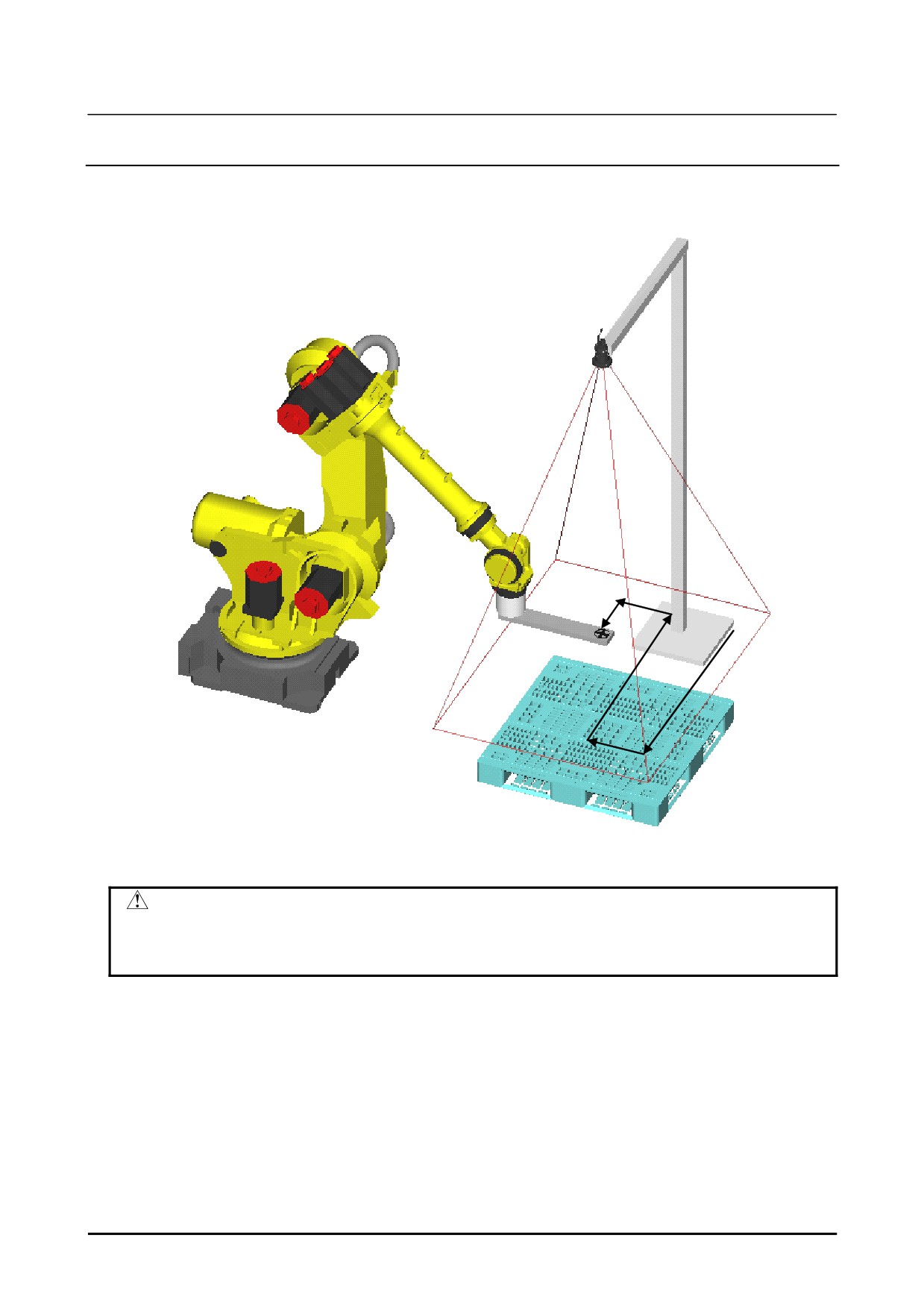
Select the generated calibration program in the SELECT menu, and play it back from the first line to
calibrate the camera. A robot moves the target as shown below.
Moving the target in a grid pattern
CAUTION
If running the program as is can cause interference, use lower override values.
In this case, execute the program while making sure that no interference occurs
during operation.
Each calibration point in the generated calibration program can be re-taught or deleted as necessary.
If there is any calibration point that causes the robot to interfere with peripheral equipment, re-teach that
point to move it to a position where it does not cause interference, or delete the calibration point. When
deleting a calibration point, delete not only the motion statement but also the lines of IRVBKLSH and the
CAMERA_CALIB command that are executed after the motion statement.
If there is any calibration point that hinders the robot operation because it is near singularity, re-teach that
point to move it to a position where it can avoid singularity, or delete the calibration point. When
deleting a calibration point, delete not only the motion statement but also the lines of IRVBKLSH and the
CAMERA_CALIB command that are executed after the motion statement.
198
B-83914EN-2/01
Know-How
2. CAMERA DATA SETTING
When re-teaching a calibration point, you may place the target closer to or further away from the camera
within a range in which the camera lens remains in focus.
CAUTION
2
The calibration program does not stop even if the target fails to be found or it is
found incorrectly during the program execution. After the program ends, open
the Robot-generated Grid Calibration setup page in the Vision Setup screen and
check to see if there is any point incorrectly found.
MEMO
As long as the position where the target is mounted remains unchanged, you can
re-calibrate the camera simply by executing the generated calibration program.
Once the program for calibration has been executed all the way to the end, the camera calibration is
complete. Check the calibration data and calibration points.
2.3.11 Checking Calibration Point
Check the calibration point found in Know-how Edition Subsection 2.3.5, "Calibration Setup".
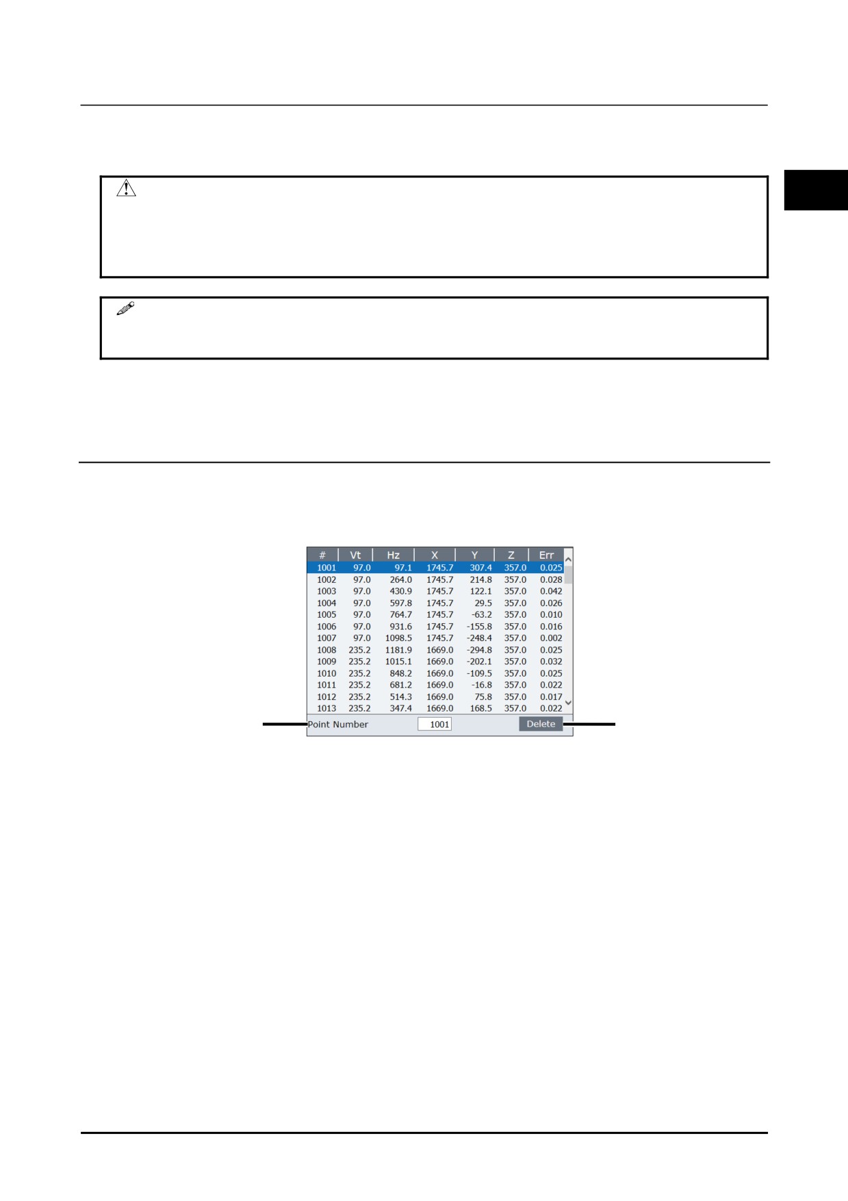
If you click [Calibration Points] in the navigation area, the calibration points screen will appear.
1
2
If there are any found points that have been found by mistake, delete the irrelevant found points using the
following procedure.
1
Select an irrelevant found point from the found point list, or enter a found point number in the [Point
Number] text box.
2
Click the [DELETE] button.
The irrelevant found point will be deleted.
B-83914EN-2/01
199
2. CAMERA DATA SETTING
Know-How
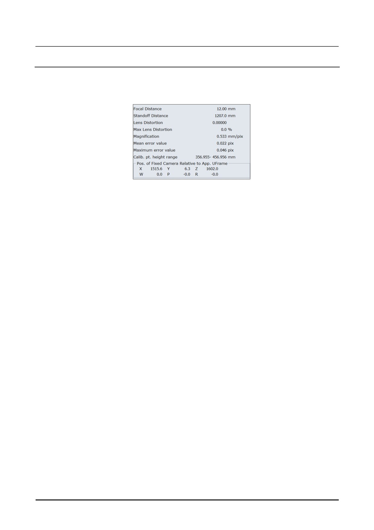
2.3.12 Checking Calibration Result
Check the calculated calibration data.
If you click [Calibration Result] in the navigation area, the calibration result screen will appear.
Check whether the focal distance is correct, and whether the position of the fixed camera relative to the
application user frame is correct.
200
B-83914EN-2/01
Know-How
3. SETUP OF SNAP IN MOTION
3 SETUP OF SNAP IN MOTION
This function enables iRVision to snap an image without stopping robot motion, and is effective when
measuring a fixed frame offset with a robot-mounted camera and/or measuring a tool offset of a part held
3
by a robot with a fixed camera or a camera mounted on another robot. Using this function will reduce
robot cycle time compared to the legacy way.
3.1
OVERVIEW OF SNAP IN MOTION
This section gives an overview of the function snap-in-motion.
3.1.1
Features
This function enables iRVision to snap an image without stopping robot motion, and is effective when
measuring a fixed frame offset with a robot-mounted camera and/or measuring a tool offset of a part held
by a robot with a fixed camera or a camera mounted on another robot. The following vision processes
support this function.
•
2D Single-view Vision Process
•
2D Multi-view Vision Process
•
Depalletizing Vision Process
•
3D Tri-View Vision Process
You can calibrate cameras and teach vision processes as is conventionally.
Calibration of a camera and teaching vision processes are performed in the state where it stopped. Even
if it is SNAP IN MOTION, that is the same method with other applications.
Obtaining an accurate robot position at a snapping moment is a key technology to measure a fixed frame
offset of part with a robot-mounted camera or a tool offset of a part held by a robot with a fixed camera or
a camera mounted on another robot.
Conventionally an accurate robot position can be obtained only while a robot remains stationary. The
function snap-in-motion enables measuring a fixed frame offset and a tool offset by getting an accurate
robot position at a snapping moment.
This function has the following restrictions.
• The robot that holds a camera or a part should be controlled by the controller on which iRVision
resides.
• Only one robot can move at a snapping moment.
When performing tool offset with a robot-mounted camera, two robots are used (a robot holding a camera
and a robot holding a part), but the position during motion can be obtained for only one of them. Stop
the other robot when snapping.
iRVision assumes a robot that can move at a snapping moment in the following manner:
• If [This Controller] is selected for Robot Holding the Part, the robot that held a part can move.
• If a robot other than [This Controller] is selected for Robot Holding the Part and [This Controller] is
selected for Robot Holding the camera, the robot that holds a camera can move.
Above conditions are used in both cases that two robots are controlled by one controller and two
controllers.
B-83914EN-2/01
201
3. SETUP OF SNAP IN MOTION
Know-How
3.1.2
Using Snap in Motion
By default, the function snap-in-motion is disabled. To use this function, change the system variable
$VSMO_CFG.$ENABLE to TRUE.
$VSMO_CFG.$ENABLE = TRUE
By setting this system variable to true, the function snap-in-motion itself is enabled. But, to snap an
image actually without stopping robot motion, you need to modify your robot program. Refer to the
Know-how Edition Subsection “3.1.4 Robot Program for Snap in Motion” about how to modify robot
programs.
By enabling the function snap-in-motion, the method to obtain a robot position at the snapping moment is
changed internally. Basically, you can use camera calibrations, vision processes and robot programs that
you taught previously even after this function is enabled. However, potentially a quantity of errors may
be observed if you continue to use camera calibrations and vision processes that you have taught before
the function is enabled. In such a case, calibrate cameras and teach the reference positions again.
3.1.3
Checking Position and Speed at Snap
When the function snap-in-motion is enabled, the actual position and speed of the robot at the last
snapping moment are recorded in the following system variables. Refer to these variables to determine
the exposure time and so on in study for application described later.
$VSMO_VAL.$POSITION
It is the actual robot position at the snapping moment. It is in the Cartesian format. X, Y and Z are in
millimeters, and W, P and R are in degrees. For a robot-mounted camera, the position of the mechanical
interface relative to the
[Application UFrame] is recorded. For tool offset, the position of the
[Application UFrame] that you selected in the camera calibration setup page is recorded.
$VSMO_VAL.$SPEED
It is the actual robot speed at the snapping moment. X, Y and Z are in mm/sec, and W, P and R are in
degrees/sec.
3.1.4
Robot Program for Snap in Motion
For snap-in-motion, you need to execute the VISION RUN_FIND instruction in a different manner from
usual.
Snap after stopping
This is an example of a program for when snapping after stopping the robot, as in the conventional
procedure. The operation mode in line 2 is ‘FINE’. The robot's motion stops while snapping under the
‘VISION RUN_FIND’ command in line 3, and the motion to move to P[3] starts when snapping is
complete.
1: L P[1:start] 500mm/sec FINE
2: L P[2:snap] 500mm/sec FINE
3:
VISION RUN_FIND 'A'
4: L P[3:stop] 500mm/sec FINE
202
B-83914EN-2/01

Know-How
3. SETUP OF SNAP IN MOTION
Snap in motion
To snap an image without stopping the robot, the VISION RUN_FIND instruction should be executed by
using the TIME BEFORE instruction. In the robot program below, ‘CNT100’ is specified for P[2] in the
second line, and the subprogram FIND.TP is called at the moment that the robot passes through P[2] by
using the TIME BEFORE instruction.
1: L P[1:start] 500mm/sec FINE
3
2: L P[2:snap] 500mm/sec CNT100 TB 0.00sec,CALL 'FIND'
3: L P[3:stop] 500mm/sec FINE
FIND.TP that is called by the TIME_BEFORE instruction is as below. The VISION RUN_FIND
function is executed in this subprogram.
1:
VISION RUN_FIND 'A'
You can tweak the start time of the TIME BEFORE instruction, or you can use the TIME AFTER
instruction or the DISTANCE BEFORE instruction instead of the TIME BEFORE instruction. For
these instructions, refer to “OPERATOR’S MANUAL(Basic Operation) B-83284EN”.
If positions P[1] ~ P[3] in the above program are not on a line, the robot moves inside of the original path
and does not pass through P[2] because of CNT100. In such a case, modify P[2] so that the robot
actually passes through the expected snap position.
3.1.5
Notes
Vibration of robot arm while robot moving is not considered. The bigger the vibration is, the larger the
error is.
3.2
STUDY FOR APPLICATION
This section describes issues to consider when the function snap-in-motion is used.
3.2.1
Light and Exposure Time
If the function snap-in-motion is used, the camera or the target is moving during the exposure, so the
snapped image will be blurred to that extent. Because this blur can cause detection error, the exposure
time should be set a smaller value than usual to mitigate the blur.
Assuming that the robot moves in the direction at a right angle to the optical axis of the camera, the
amount of blur is calculated by the expression V × T × N ÷ S in pixels, where V is the velocity at the
snapping moment in mm/sec, T is the exposure time in sec, S is the size of the camera field of view in
millimeters and N is the number of effective pixels of the camera.
(Pixels) = V × T × N ÷ S
Determine the exposure time so that this amount of blur is smaller than one pixel and prepare a good light
source to get a fully bright image with the selected exposure time.
B-83914EN-2/01
203
3. SETUP OF SNAP IN MOTION
Know-How
3.2.2
Image Processing Time and Motion Time
When using the function to capture without stopping, it is necessary to pay attention to the relationship
between the time required for image processing and the time required for robot operation.
GET_OFFSET
The following program calls the subprogram FIND.TP, which include the VISION RUN_FIND
instruction, at the moment that the robot passes through P[2] in the second line, and tries to get the
resulting vision offset in the line 4. If P[2] and P[3] were too close and the robot reached P[3] in a short
time, the robot would wait for the completion of vision detection in the fourth line, resulting the robot
stopping. To avoid such a thing, consider a good layout of the camera so that the image processing
finishes while the robot is moving from P[2] to P[3].
1: L P[1:start] 500mm/sec CNT100
2: L P[2:snap] 500mm/sec CNT100 TB 0.00sec,CALL FIND
3: L P[3:stop] 500mm/sec CNT100
4:
VISION GET_OFFSET 'A' VR[1] JMP,LBL[1]
5: L P[4:approach] 500mm/sec FINE VOFFSET,VR[1]
Continuous RUN_FINDs
In iRVision, vision detection that has been executed first has to be completed before the next vision
detection can be started. Therefore, if you start up vision detection consecutively in a short interval, the
vision detection that comes after will be kept waiting, and as a result, it will not be able to snap an image
at the expected position.
For example, in the following program, if the time to move from P[2] to P[3] is shorter than the time for
the image processing for FIND1.TP, snapping an image for FIND2.TP will be delayed.
1: L P[1:start] 500mm/sec CNT100
2: L P[2:snap1] 500mm/sec CNT100 TB 0.00sec,CALL FIND1
3: L P[3:snap2] 500mm/sec CNT100 TB 0.00sec,CALL FIND2
4: L P[4:stop] 500mm/sec CNT100
Time a vision process takes depends on the shape of the trained model pattern, the detection parameters,
the condition of the snapped image, and the load of the controller that performs the vision process.
Check your vision process time by actually executing the vision process.
In addition, if the vision process executed previously is configured to log images, the next vision process
can be kept waiting until the previous vision process completes image logging and snapping an image of
the next vision process can be delayed. In such a case, configure the previous vision process not to log
images. The delay of snapping an image can be shortened slightly if the ‘Enable Logging’ is checked
off in the iRVision configuration setup page.
3.2.3
Shift of Snap Position
Depending on the condition of the controller, timing of snap may be fluctuated slightly. The shift of the
snap timing is basically no problem, because iRVision can get an accurate robot position at snapping.
But if the size of the camera field of view is adjusted so that an image is filled with a part, the shift of the
snap timing lead the part being out of the camera field of view and that causes detection failure. Set the
size of the camera field of view to have enough margins to accept a quantity of the shift of the snap
timing. The size of margin depends on the speed of the robot at snapping. The faster the robot is
moving, the bigger the shift of the snapping position is.
Moreover, after turning on a controller, in the first vision detection, detection time may take a few
seconds longer. About the detection time of the second times, it becomes the normal detection speed.
At the detection of first time, when the shift of the snap timing occurs, perform the detection of first time
at somewhere else before the performing snap in motion.
204
B-83914EN-2/01
Know-How
3. SETUP OF SNAP IN MOTION
NOTE
Vision Processes are saved in the FROM or memory card. In addition, If Vision
Process is performed, it will remain in the cache in DRAM. Since access to the
file in cache is quick, the vision detection of second time becomes early rather
than the first time. Since Vision processes in the cache are deleted at the
turning off a control, the detection speed at first time after turning on a control
3
may become long. In addition, there is a limitation in the cache domain of
DRAM. So other Vision Processes are run, old Vision Processes in the cache
will be deleted from cache. In the system that runs many kinds of Vision
Processes in one cycle, some of the executed Vision Processes may not remain
in cache. The capacity of cache is 2 MB as an initial value.
3.3
SAMPLE APPLICATIONS
This section demonstrates three sample applications using the function snap-in-motion.
• Tool offset with a fixed-mounted camera (2D Single-view Vision Process)
• Tool offset with a fixed-mounted camera (2D Multi-view Vision Process)
• Fixed frame offset with a robot-mounted camera (3D Tri-view Vision Process)
In either application, generally the setup procedure and items to consider are the same as those of each
application without the function snap-in-motion. The descriptions about the area of overlap with those
in each vision processes are left out.
3.3.1
Tool Offset with a Fixed Camera (2D single-view vision
process)
Tool offset with a fixed camera (2-D Single-view vision process) measures the amount of tool offset by
snapping the workpiece that the robot is gripping, using a fixed camera. Using the measured tool offset,
the robot positions are compensated to put the part in a correct position. The tool offset is usually
measured with stopping the robot. Using the function snap-in-motion, the vision detection can be
executed while the robot is transporting a part without stopping robot motion.
The subsection “1.4.4 Robot Program Creation and Teaching” in the setup procedure described in the
section “1.4 SETUP FOR TOOL OFFSET WITH FIXED CAMERA” is different from those using the
function snap-in-motion.
‘Robot Program Creation and Teaching’ is explained below.
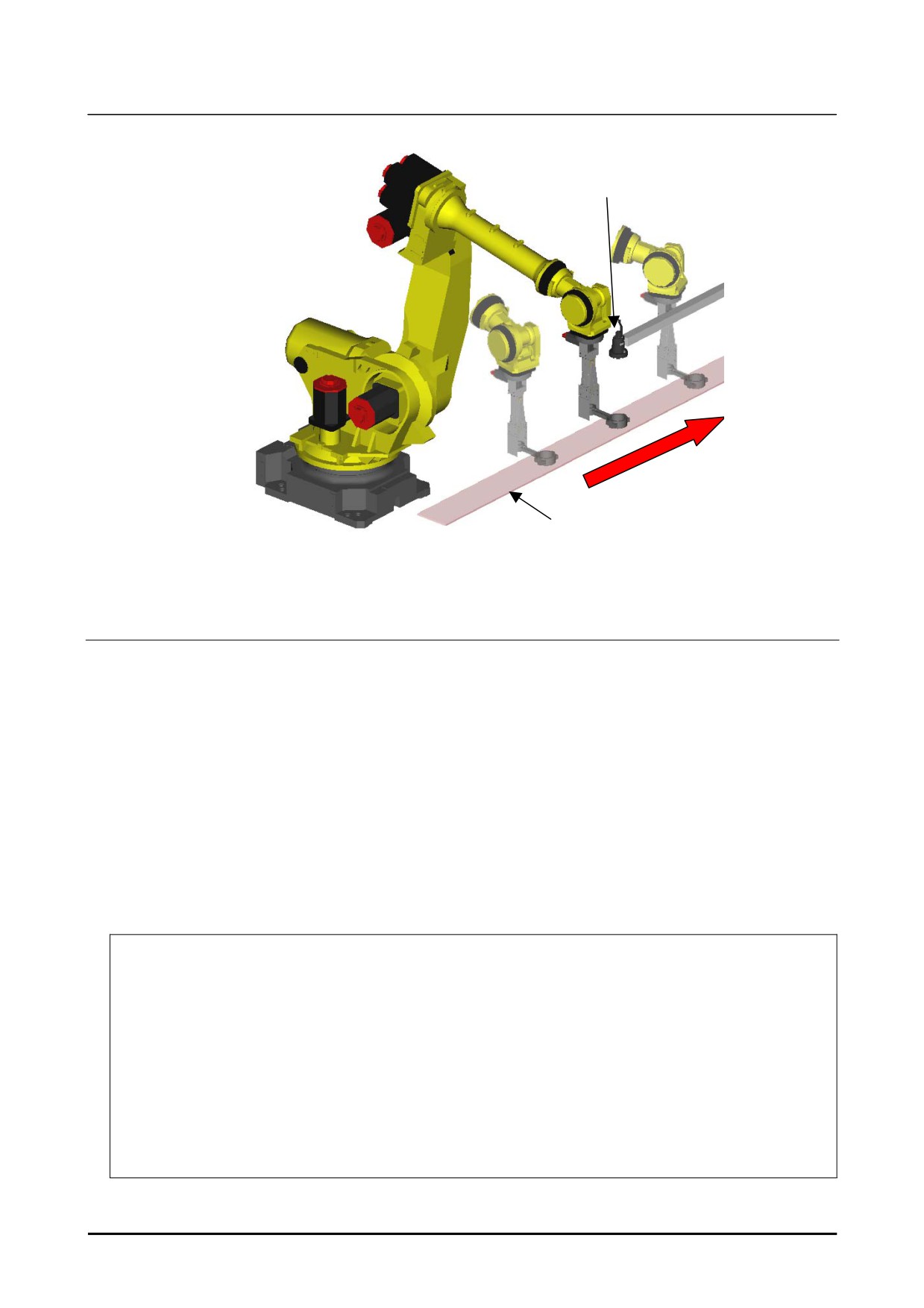
The figure below is an example of layout in the case of tool offset using 2D Single-view Vision Process
with a fixed-mounted camera.
B-83914EN-2/01
205
3. SETUP OF SNAP IN MOTION
Know-How
Camera
Compensation plane
Tool offset with a fixed camera (2-D Single-View Vision Process)
3.3.1.1 Robot program creation and teaching
This subsection demonstrates robot programs for tool offset in motion. Based on sample robot programs
below, create appropriate robot programs for your application.
The following two programs are created.
• Main robot program (MAIN.TP)
• Robot program to detect a target (FIND.TP)
MAIN.TP
This is the main program. In this program, the robot moves from the start position P[1] to the stop
position P[3] through the snap position P[2], and call the subprogram FIND.TP at the moment that the
robot passes through the snap position. After that, the VISION GET_OFFSET instruction is called to
get the resulting vision offset. The robot positions P[4] and P[5] are compensated with the vision offset
so that the part is put at the correct location.
1:
UFRAME_NUM=1
2:
UTOOL_NUM=1
3:
4: L P[1:start] 500mm/sec CNT100
5: L P[2:snap] 500mm/sec CNT100 TB 0.00sec,CALL FIND
6: L P[3:stop] 500mm/sec CNT100
7:
VISION GET_OFFSET 'A’ VR[1] JMP LBL[99]
8: L P[4:approach] 500mm/sec FINE VOFFSET,VR[1]
9: L P[5:set] 100mm/sec FINE VOFFSET,VR[1]
10: L P[4:approach] 100mm/sec FINE VOFFSET,VR[1]
11:
END
12:
LBL[99]
13:
UALM[1]
206
B-83914EN-2/01
Know-How
3. SETUP OF SNAP IN MOTION
FIND.TP
This is a program called by the TIME BEFORE instruction. This program executes the vision process
“A” using the VISION RUN_FIND instruction.
1:
VISION RUN_FIND 'A'
3
3.3.2
Tool Offset with a Fixed Camera (2D multi-view vision
process)
Tool offset with a fixed camera (2-D Multi-View Vision Process) measures the amount of tool offset of a
workpiece by snapping multiple features on a large workpiece that the robot is gripping, using a fixed
camera. Using the measured tool offset, robot positions are compensated to put the part at a correct
position.
The tool offset is usually measured with stopping the robot. Using the function
snap-in-motion, the vision detection can be executed while the robot is transporting a part without
stopping robot motion.
The subsection “2.4.4 Robot Program Creation and Teaching” in the setup procedure described in the
section “2.4 SETUP FOR TOOL OFFSET WITH FIXED CAMERA” is different from those using the
function snap-in-motion.
‘Robot Program Creation and Teaching’ is explained below.
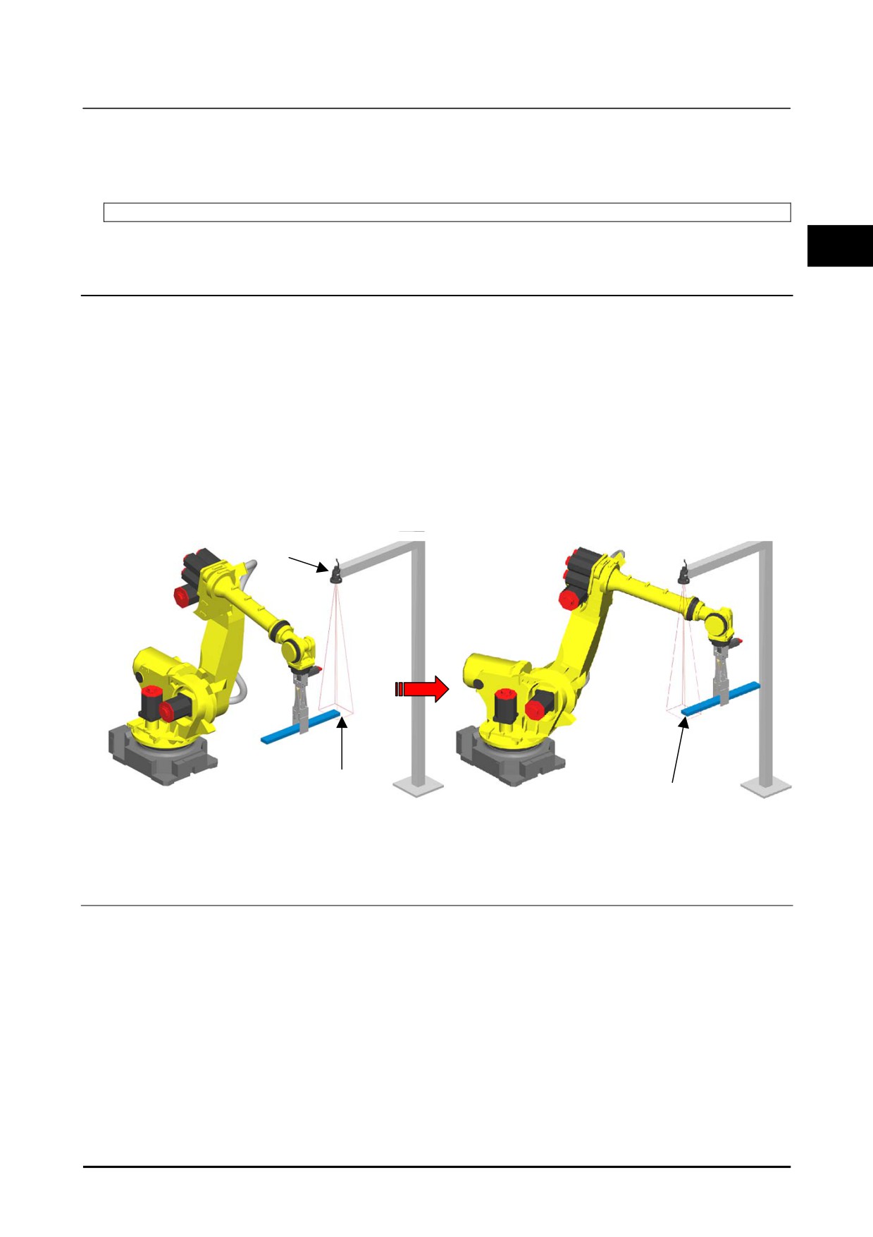
The figure below is an example of layout in the case of tool offset using 2D Multi-view vision process
with a fixed-mounted camera.
Camera
1st view position
2nd view position
Tool offset with a fixed camera (2-D Multi-View Vision Process)
3.3.2.1 Robot program creation and teaching
This subsection demonstrates robot programs for tool offset in motion. Based on sample robot programs
below, create appropriate robot programs for you application.
Following two programs are created.
• Main robot program (MAIN.TP)
• Robot program to detect a target (FIND.TP)
B-83914EN-2/01
207
3. SETUP OF SNAP IN MOTION
Know-How
MAIN.TP
This is the main program. In this program, the robot moves from the start position P[1] to the stop
position P[4] through the two snap positions P[2] and P[3], and calls the subprogram FIND.TP with a
camera view number as an argument at the moment that the robot passes through the snap positions. In
order to confirm that the vision processes are completed in every camera view, it waits until R[1]
becomes 2. After that, the VISION GET_OFFSET instruction is called to get the resulting vision offset.
The WAIT instruction secures that the VISION GET_OFFSET instruction is executed after the VISION
RUN_FIND completion. The robot positions P[5] and P[6] are compensated with the vision offset so
that the part is put at the correct location.
1:
UFRAME_NUM=1
2:
UTOOL_NUM=1
3:
4:
R[1]=0
5: L P[1:start] 500mm/sec CNT100
6: L P[2:snap1] 500mm/sec CNT100 TB 0.00sec,CALL FIND(1)
7: L P[3:snap2] 500mm/sec CNT100 TB 0.00sec,CALL FIND(2)
8: L P[4:stop] 500mm/sec CNT100
9:
WAIT R[1]>=2
10:
VISION GET_OFFSET 'A' VR[1] JMP LBL[99]
11: L P[5:approach] 500mm/sec FINE VOFFSET,VR[1]
12: L P[6:set] 100mm/sec FINE VOFFSET,VR[1]
13: L P[5:approach] 500mm/sec FINE VOFFSET,VR[1]
14:
END
15:
LBL[99]
16:
UALM[1]
FIND.TP
This is a program called by the TIME BEFORE instruction. This program executes detection of the
camera view specified by the argument using the VISION RUN_FIND instruction. And R[1] is
incremented after the image acquisition completes.
1:
VISION RUN_FIND 'A' CAMERA_VIEW[AR[1]]
2:
R[1]=R[1]+1
208
B-83914EN-2/01
Know-How
3. SETUP OF SNAP IN MOTION
3.3.3
Fixed Frame Offset with a Robot Mounted Camera (3D
Tri-view vision process)
In a fixed frame offset application with a robot-mounted camera of 3D Tri-view Vision Process, three
features on a part are detected by the robot mounted-camera and the 3D position of the part is measured.
Using the measured position, robot positions are compensated so that the tool of the robot can reach the
3
part. The fixed frame offset is usually measured with stopping the robot.
Using the function snap-in-motion, the measurements can be executed continuously without stopping the
robot holding the camera at each snap position.
The subsection “4.3.3 Robot Program Creation and Teaching” in the setup procedure described in the
section “4.2 SETUP FOR FIXED FRAME OFFSET WITH FIXED CAMERA” is different from those
using the function snap-in-motion.
“ROBOT PROGRAM CREATION AND TEACHING” is explained
below.
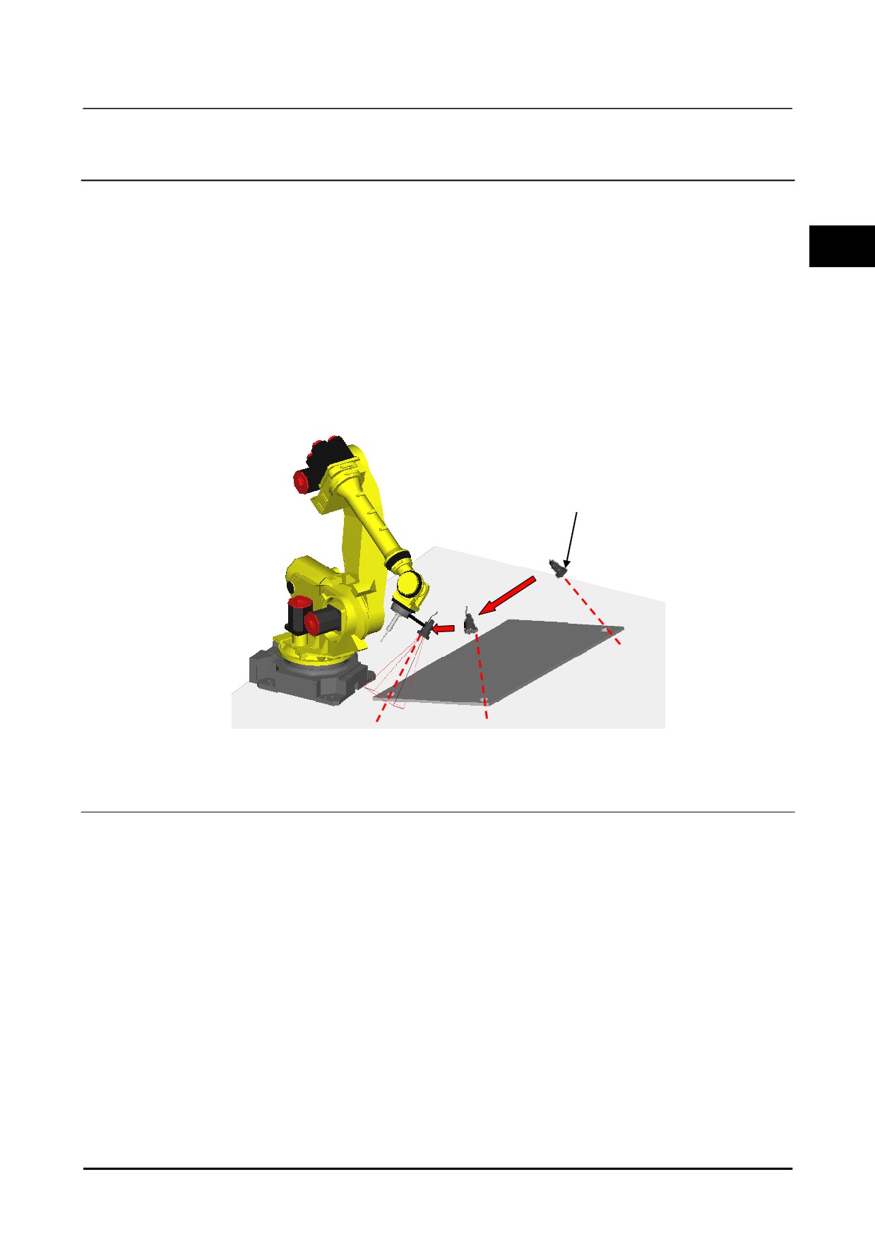
The figure below is an example of layout in the case of fixed frame offset using 3D Tri-view vision
process with a robot-mounted camera.
Camera
Tool offset with a fixed camera (3-D Tri-View Vision Process)
3.3.3.1 Robot program creation and teaching
Here, examples of robot programs for performing snap-in-motion and fixed frame offset are described.
Change the programs to suit each system, referring the robot programs described here.
The following two robot programs will be created.
• Main robot program (MAIN.TP)
• Detection robot program (FIND.TP)
MAIN.TP
This is a main program. In this program, the robot moves from the start position P[1] to the stop
position P[5] through the three snap positions P[2] ~ P[4], and calls the subprogram FIND.TP with a
camera view number as an argument at the moment that the robot passes through each snap position. To
confirm that the vision processes are completed in every camera view, it waits until R[1] become 3.
After that, the VISION GET_OFFSET instruction is called to get the vision offset. The WAIT
instruction can prevent that the VISION GET_OFFSET instruction executes previously rather than
VISION RUN_FIND is completed. The robot positions P[6] and P[7] are compensated with the vision
offset so that the robot holds the part.
B-83914EN-2/01
209
3. SETUP OF SNAP IN MOTION
Know-How
1:
UFRAME_NUM=1
2:
UTOOL_NUM=1
3:
4:
R[1]=0
5: L P[1:start] 500mm/sec CNT100
6: L P[2:snap1] 500mm/sec CNT100 TB 0.00sec,CALL FIND(1)
7: L P[3:snap2] 500mm/sec CNT100 TB 0.00sec,CALL FIND(2)
8: L P[4:snap3] 500mm/sec CNT100 TB 0.00sec,CALL FIND(3)
9: L P[5:stop] 500mm/sec CNT100
10:
WAIT R[1]>=3
11:
VISION GET_OFFSET 'A' VR[1] JMP LBL[99]
12: L P[6:approach] 500mm/sec FINE VOFFSET,VR[1]
13: L P[7:hold] 100mm/sec FINE VOFFSET,VR[1]
14: L P[6:approach] 500mm/sec FINE VOFFSET,VR[1]
15:
END
16:
LBL[99]
17:
UALM[1]
FIND.TP
This is a program called by the TIME BEFORE instruction. This program executes detection in the
camera view specified by the argument using the VISION RUN_FIND instruction. And R[1] is
incremented after the image acquisition completes.
1:
VISION RUN_FIND 'A' CAMERA_VIEW[AR[1]]
2:
R[1]=R[1]+1
210
B-83914EN-2/01
Know-How
4. FAQS FOR TROUBLESHOOTING
4 FAQS FOR TROUBLESHOOTING
4.1
METHOD FOR ADJUSTMENTS AFTER CAMERA
REPLACEMENT
I don't know how to make adjustments after camera replacement
4
Measures:
If the camera breaks for some reason, replace it and readjust using the following
procedure.
1
Cut off the power supply to the robot controller. By cutting off the power supply
to the robot controller, the power supply to the camera will be cut off.
2
Remove the camera. When doing this, be careful not to apply any pressure to
the diaphragm and the focus ring of the lens.
3
Remove the lens from the camera.
4
Attach the lens that was removed in step 3 to the new camera.
5
Install the camera and fix it in place.
6
Perform camera calibration.
The work is now complete.
Before removing a camera that is in operation, double-check that the diaphragm of the
lens and the focus ring are fixed securely in place and will not move.
Furthermore, the lens is reusable. If you replace the lens without moving the focus or
the lens ring, readjustment of the locator tools will be unnecessary, which will make
the work easier.
4.2
VISION DATA RECOVERY
I don't know how to recover vision data
Measures:
Recover vision data using the following procedure.
1
Prepare a memory card on which you have made a backup in accordance with the
procedure in Introduction Edition Section
2.7, "MEMORY CARD
PREPARATION".
2
The extension for vision data files is VD. If you load all the *.VD files, the
vision data will be recovered.
Be careful with the version ID if the robot controller to copy from is different from the
robot controller to copy to. The version ID of the robot controller to copy to needs to
be the same or higher than that of the robot controller to be copied from.
B-83914EN-2/01
211
4. FAQS FOR TROUBLESHOOTING
Know-How
4.3
DETECTION PROBLEMS
The expected workpiece is not being detected (not found)
Measures:
Please check the following.
• Set it so that logged images are saved, and save the not-found image. Adjust the
locator tool parameters using several images for which detection failed. If
saving logged images, refer to Setup Edition Section 1.7, "VISION CONFIG" in
"R-30iB Plus CONTROLLER iRVision OPERATOR’S MANUAL (Reference)
B-83914EN". After finishing adjustment, change the settings so that images will
not be saved. The detection time may be longer if found images are being saved.
• Adjust the parameters while referring to the logged images. By placing a check
by [Show Almost Found], you will be able to tell which parameter settings are
causing the not-founds.
• If part of the image is causing halation so that the workpiece is difficult to see, the
effect may be reduced to some extent by using the multi exposure function.
However the detection time may be longer if the multi exposure function is used.
If it is necessary to reduce the detection time, do not using multi exposure to
prevent halation, but rather, change the position of the lighting, etc.
• If the contrast between the workpiece and the background is low, the workpiece's
features may not be seen clearly. When detecting the outline of a workpiece
with a pattern match tool, if the workpiece is light-colored, the workpiece will be
seen clearly if you set the background to a dark color.
• When applying the
[Depalletizing Vision Process], if detection becomes
impossible when the number of layers is changed, check whether the [Scale] for
the DOF has been set to something valid.
212
B-83914EN-2/01
Know-How
4. FAQS FOR TROUBLESHOOTING
A different workpiece from the expected one is being detected (false
detection)
Measures:
Please check the following.
•
Set it so that logged images are saved, and save the false-detection image.
Adjust the locator tool parameters using several images for which detection failed.
If saving logged images, refer to Setup Edition Section 1.7, "VISION CONFIG"
in "R-30iB Plus CONTROLLER iRVision OPERATOR’S MANUAL
(Reference) B-83914EN". After finishing adjustment, change the settings so that
4
images will not be saved. The detection time may be longer if found images are
being saved.
•
Adjust the parameters while referring to the logged images. You can make
adjustments using methods like the following:
-
Reduce the search area to until it is the smallest one that is necessary.
-
Set the DOF for [Orientation], [Scale], and [Aspect] to the smallest that are
necessary.
-
Reduce [Elasticity].
-
Reduce the setting value for [Area Overlap].
-
Set the [Emphasis Area].
•
If the workpiece has only a few model features, matching will be likely to occur at
various places within the field of view, which makes it easy for false detection to
occur. By increasing the number of model features, you will be able to perform
detection that is less likely to be affected by noise. If the number of model
features is increased, the detection score may decrease compared to when the
model had only few features. In such cases, set the score to something low.
Even if the score is set to something low, it will still be effective as a
false-detection prevention measure if the number of model features is increased.
•
Enabling [Ignore Polarity] in the setting items for things like pattern match will
make it easy for false detection to occur. It should basically be set to disabled.
B-83914EN-2/01
213
4. FAQS FOR TROUBLESHOOTING
Know-How
I don't know how to redetect
Measures:
If detection has failed owing to a not-found, etc., the detection can be retried using
vision override while changing the detection parameters. For details on vision
override, refer to Setup Edition Section 5.1, "VISION OVERRIDE" in the "R-30iB
Plus CONTROLLER iRVision OPERATOR’S MANUAL(Reference) B-83914EN".
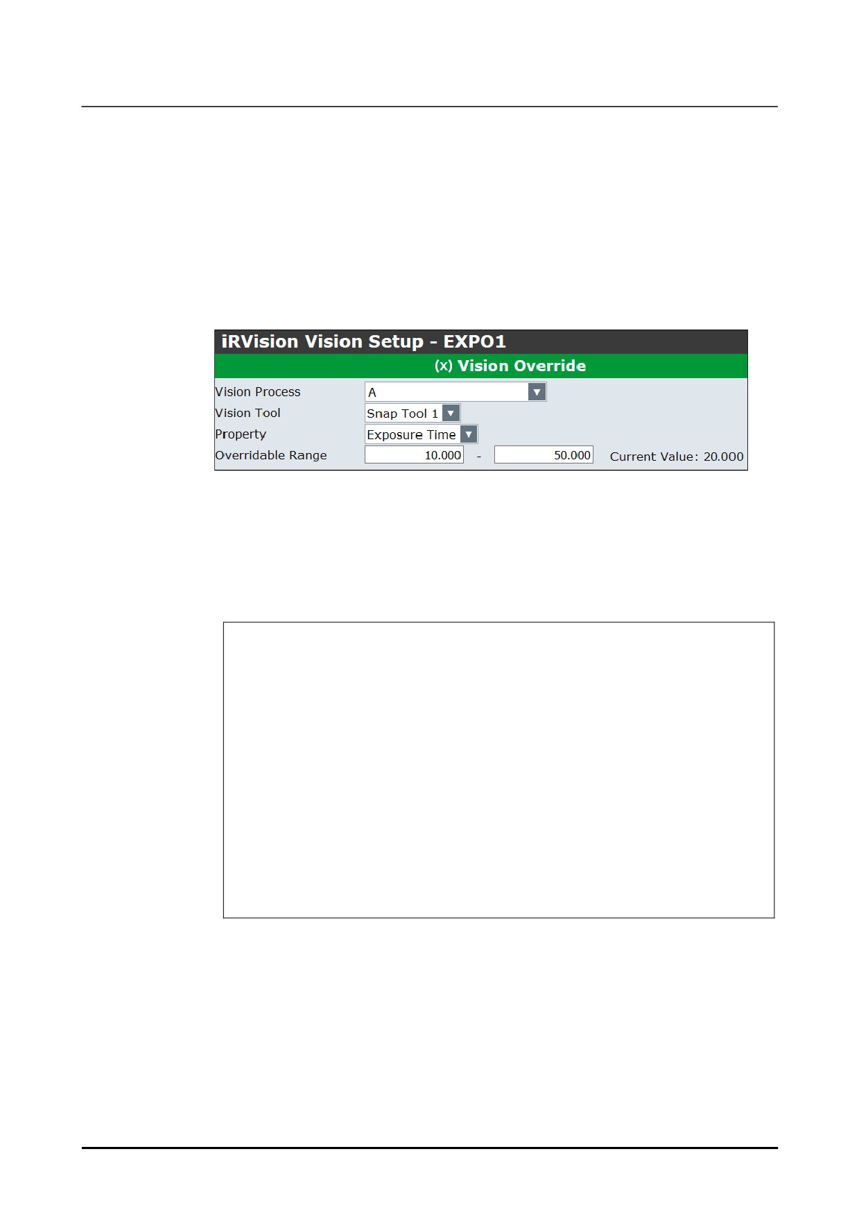
An example of retry while changing the exposure time in a 2-D single-view vision
process is shown below.
The following figure is the setup screen for vision override. Suppose that the vision
process name is 'A', and the vision override name is 'EXPO1'.
The following is a sample program. Vision detection is performed in line 15. As an
example, the exposure time here is set to 20 ms. If the vision detection has failed, a
vision variable setting instruction is called in line 20, and the exposure time is changed
to the value stored in register [5] (for example, 25 ms). If detection is performed
again in this state by executing vision process 'A' in line 15, an image will be snapped
with an exposure time of 25 ms.
12: R[20:retry]=0
;
13: R[15:notfound]=0
;
14: LBL[100] ;
15: VISION RUN_FIND 'A'
;
16: VISION GET_OFFSET 'A' VR[1] JMP LBL[10] ;
17: JMP LBL[20] ;
18: LBL[10] ;
19: IF R[20:retry]=1,JMP LBL[900] ;
20: VISION OVERRIDE 'EXPO1' R[5] ;
21: R[20:retry]=1
;
22: JMP LBL[100] ;
23:
;
24: LBL[20] ;
;
34: LBL[900] ;
35: R[15:notfound]=1
;
;
Vision override does not overwrite the content of the vision process itself. The values
that are overwritten by override are only enabled for the vision detection instruction
immediately after the vision variable setting instruction is executed. Once the vision
detection instruction is executed, all values set by the vision variable setting instruction
(and all vision variables related to vision processes other than the one that executed
detection) will be cleared.
214
B-83914EN-2/01
Know-How
4. FAQS FOR TROUBLESHOOTING
The lighting environment is not stable
Cause:
In an environment where the intensity in the field of view is not constant between day
and night, detection may not be stable.
Measure 1:
By using the auto exposure function, detection that is resistant to intensity changes can
be performed. Auto exposure is a function that automatically selects the exposure
time in response to the ambient environment so that the intensity of a snapped image
will be the same as that of a reference image. This is done by registering in advance
4
an image with an intensity to use as the reference.
How to specify the auto exposure area
Specify the auto exposure area. The image that was being displayed when you set the
auto exposure area will be the reference image for auto exposure. Set up the auto
exposure area using the following procedure.
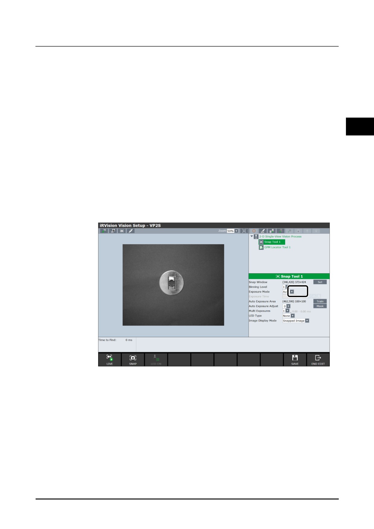
1
From the [Exposure Mode] drop-down box, select [No].
2
Adjust the exposure time so that the image has an appropriate intensity.
3
In the [Exposure Mode] drop-down box, change the selection to [Auto].
Click [OK] on the displayed pop-up that asks for the auto exposure area to be
taught.
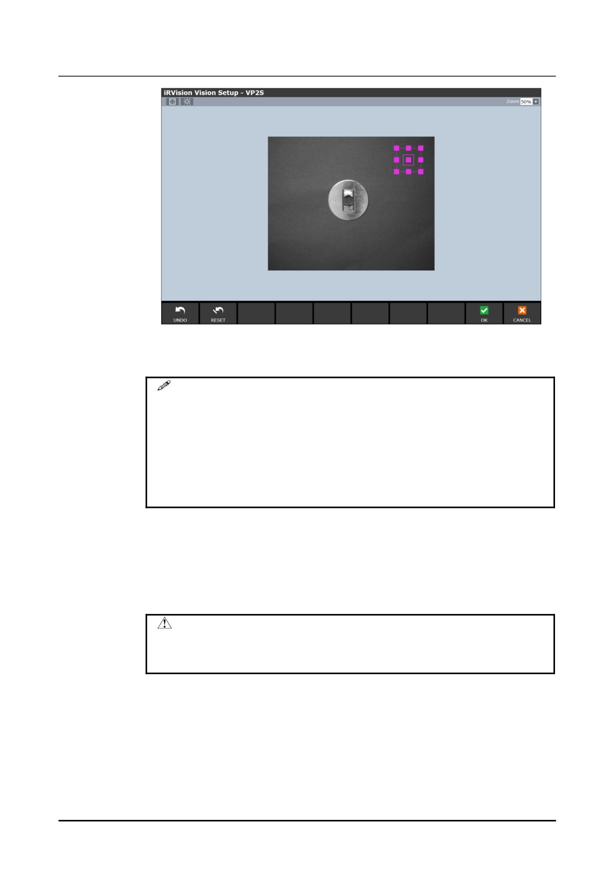
4
Set the auto exposure area.
•
If the auto exposure area has not been taught yet, a window for teaching the
auto exposure area will appear, so set the auto exposure area using the
window.
•
If the auto exposure area has already been taught, click the [Train] button for
[Auto Exposure Area] to change the position and size of the auto exposure
area.
B-83914EN-2/01
215
4. FAQS FOR TROUBLESHOOTING
Know-How
5
If there is a section you want to ignore in the auto exposure area, click the [Mask]
button and mask the section you want to ignore.
MEMO
1 A section in the image that is completely white or completely black
cannot be specified as the auto exposure area. Set a section that
has intermediate colors to be the auto exposure area.
2 A section in which the image changes significantly is not suitable as
an auto exposure area. For example, in a place where there is
sometimes a workpiece and sometimes not, stable photometry
cannot be performed, as the intensity of its appearance will change
significantly depending on the presence or absence of a workpiece.
How to make fine adjustments for auto exposure
Fine adjustments can be made in auto exposure so that an image will be snapped that
has an intensity that is a little brighter or darker than that of the set reference image.
A value from -5 to +5 can be selected. The larger the value gets in the + direction, the
brighter the image will be, and the larger the value gets in the - direction, the darker the
image will be.
CAUTION
As auto exposure and multi exposures create a single image by
snapping multiple images at a time, the snap-in-motion function
cannot be used.
216
B-83914EN-2/01
Know-How
4. FAQS FOR TROUBLESHOOTING
Measure 2:
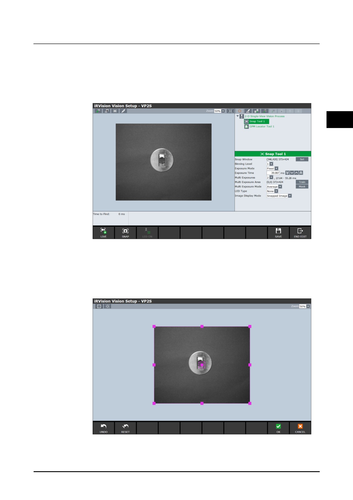
Multi exposure snaps multiple images using different exposure times, and creates an
image with a wide dynamic range by combining them. The same as with auto
exposure, detection that is resistant to intensity changes can be performed. Specify
the number of images to snap. A number between 1 and 6 can be set. The more
images are taken, the wider the dynamic range will be, but the time it takes to snap the
images will also be longer. Also the outlines in the image may be blurred overall.
4
How to specify the multi exposure area
Specify the exposure area used for multi exposure. Images are combined on the basis
of the intensity inside the multi exposure area. The whole of the screen is set by
default, and normally, this does not need to be changed. To set the multi exposure
area, click the [Train] button and set the window. If there is a section you want to
ignore in the auto exposure area, click the [Mask] button and mask the section you
want to ignore.
B-83914EN-2/01
217
4. FAQS FOR TROUBLESHOOTING
Know-How
Multi Exposure Mode
Select the method for combining the images in multi exposure.
• Deviation
For the images in a multi exposure area, the deviation of the luminance is
calculated, and the images are combined in such a way that only a few pixels that
cause halation will remain. This is the default setting.
• Maximum
Images are combined by suppressing the maximum luminance so that the images
in the multi exposure area do not cause halation. If there is even a part of the
multi exposure area where halation is occurring at even a single point in, all other
parts will become relatively darker.
• Average
A combination method that simply calculates the average intensity of each image.
Although it is the method for which the dynamic range is widest, the image will
be darker overall.
CAUTION
As auto exposure and multi exposures create a single image by
snapping multiple images at a time, the snap-in-motion function
cannot be used.
Detection is taking a long time
Cause 1:
A loop using an upward jump label that includes an operation statement with a
movement distance that is 0 has been programmed in.
Depending on how the TP program is created, it may not be possible to process vision
data because almost all of the CPU's capacity will be used for program execution.
Specifically, this applies in cases where a program with a loop that uses an upward
jump has been created, and in that loop, there is an operation statement for which the
movement distance is zero. In such cases, if there is an 'operation statement for
moving to a waiting position', then the movement distance of the operation statement
will be zero starting from the second run of the loop.
Measures:
You can check whether the TP program has the above logic or not by changing the
value of the system variable $PG_CFG.$JMPWAIT_UPR to '16' (the default is '-16').
CAUTION
Changing the above system variable will put the system into the
same state as if a WAIT of 16 ms had been entered in all the
upward jumps. If there is a problem with application as a result of
this change, analyze the TP program to identify the loop that is
causing the problem, and enter a WAIT instruction in that loop (set
the system variable back to the default).
Cause 2:
The execution history is being saved.
Measures:
If the execution history is being saved using a USB memory, it may take a long time to
perform vision detection.
218
B-83914EN-2/01