FANUC R-30iB Plus CONTROLLER, iRVision 2D Camera Application. OPERATOR'S MANUAL - page 6
Know-How
1. FRAME SETTING
1
17
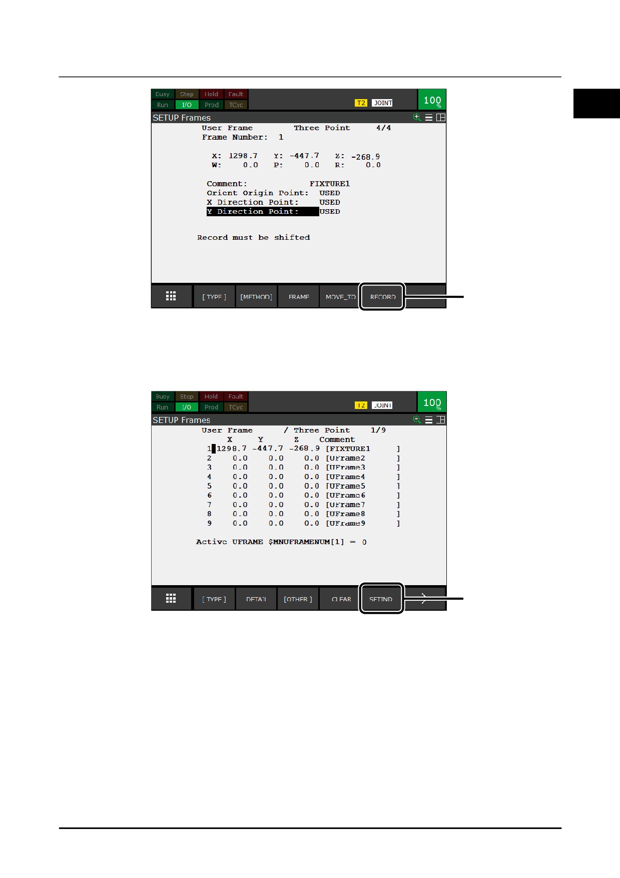
17 While holding down the [SHIFT] key, press F5 [RECORD].
When all the touch-up points are taught, [Used] will be displayed. The user frame will be set.
18 Press the [PREV] key.
The User Frame list screen will appear.
19
19 Press F5 [SETIND] and enter a frame number.
The user frame that has been set will be set as the currently enabled user frame.
B-83914EN-2/01
133
1. FRAME SETTING
Know-How
Four point method
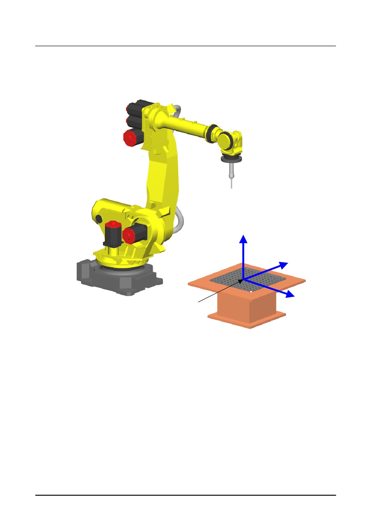
Teach the following four points: the origin of the x−axis parallel to the frame, the point which specifies
the positive direction of the x−axis, a point on the x−y plane, and the origin of the frame. In the example
of the following figure, the user frame is set on the fixed calibration grid.
Z
Y
X
System origin
Example of setting a user frame on a fixed calibration grid
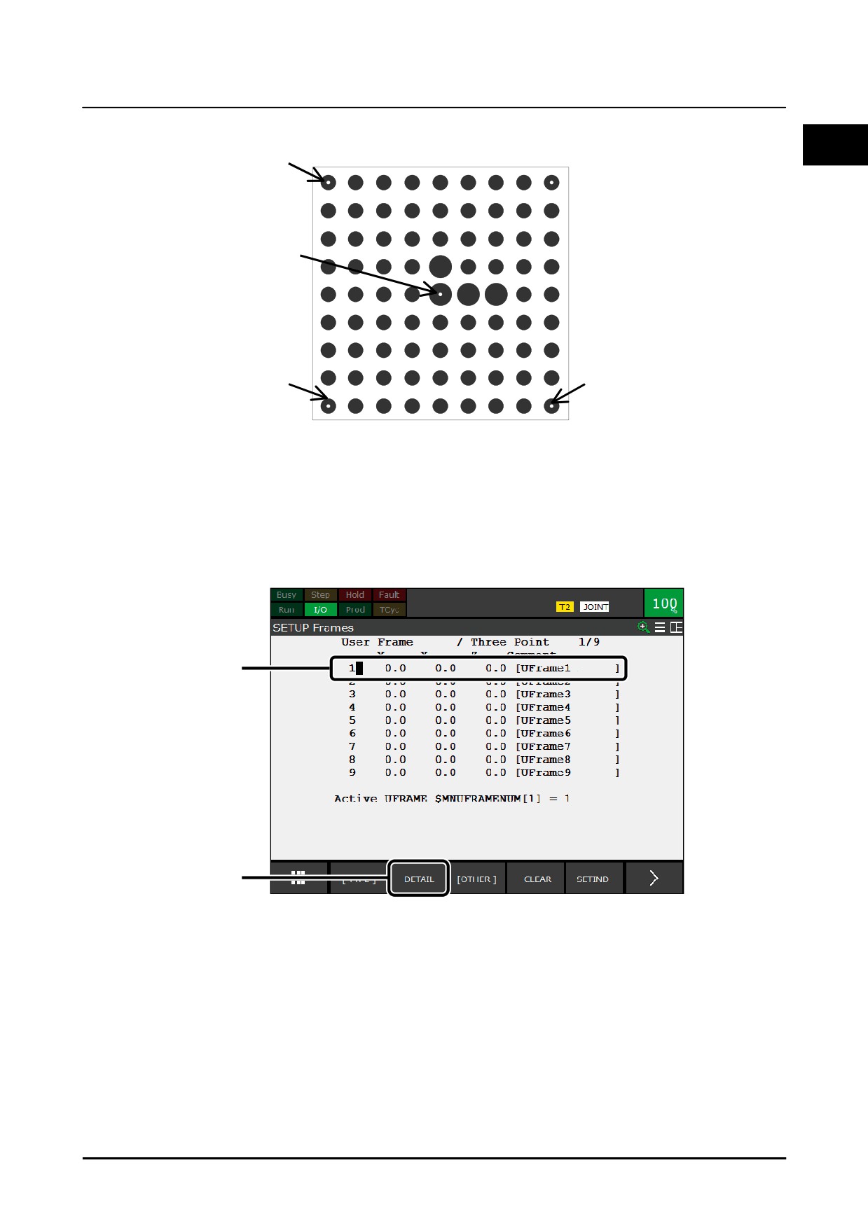
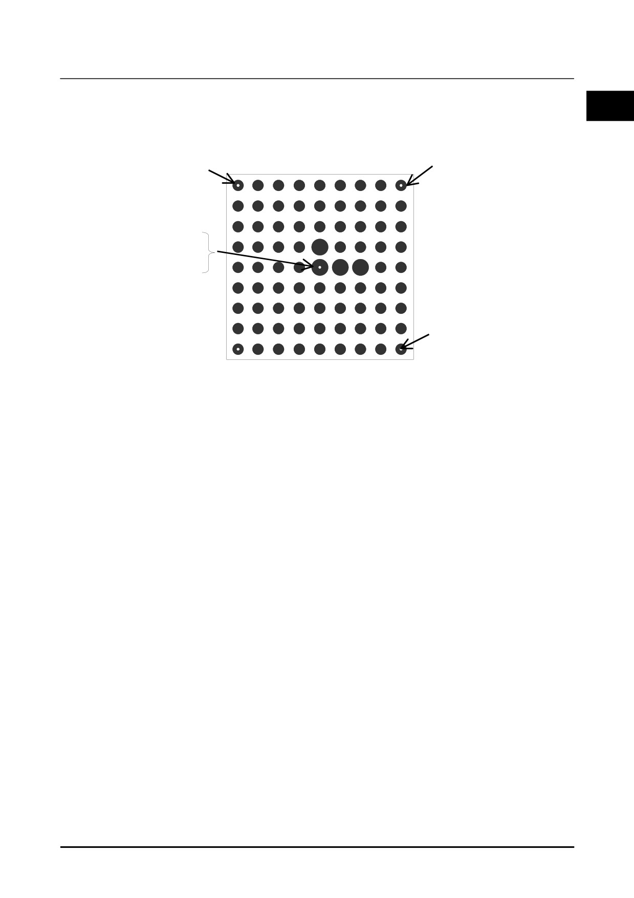
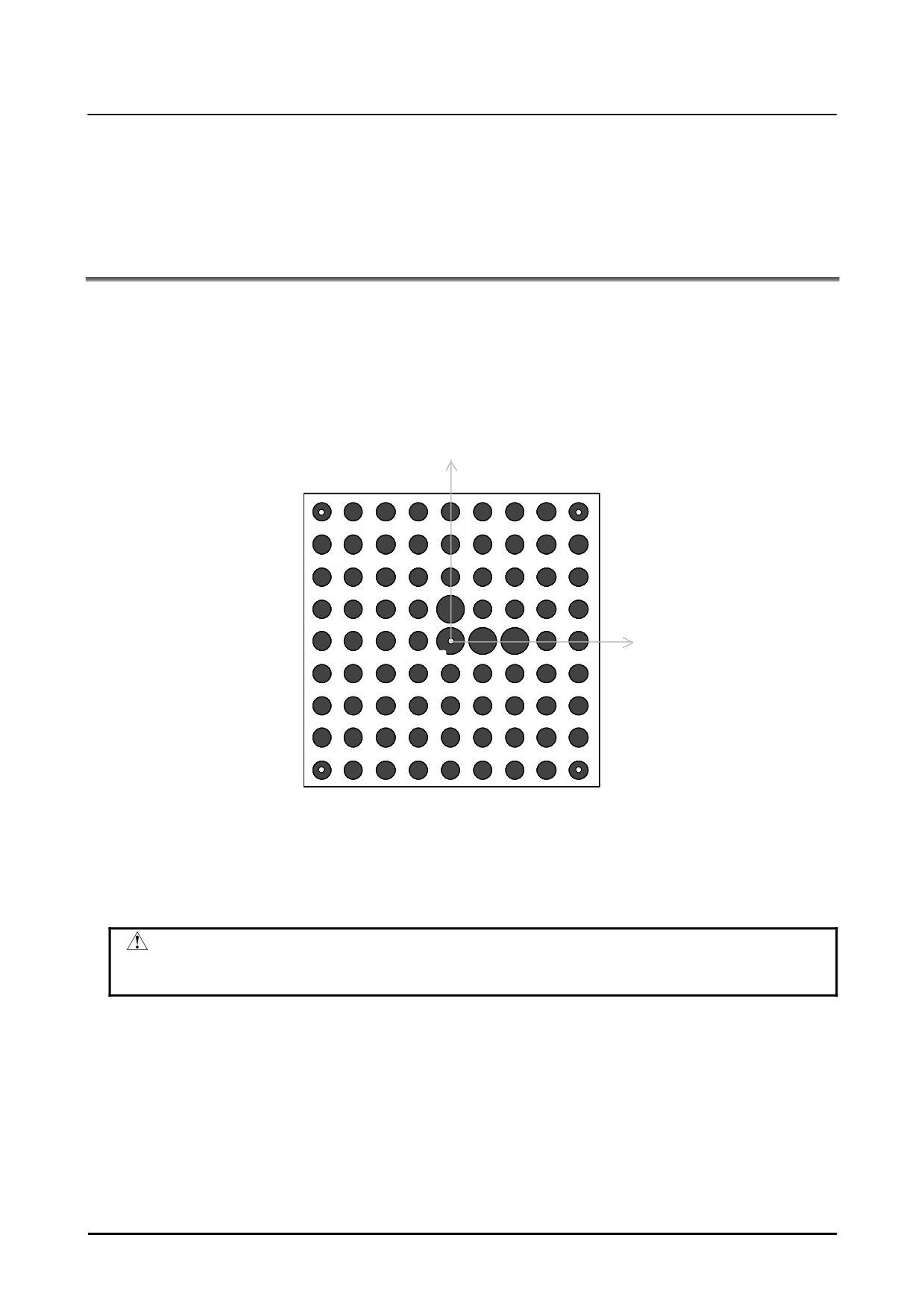
The following figure is a calibration grid. When perform the Grid Pattern Calibration for camera
calibration, it is necessary to set up a user frame such as shown in the following figure. Since it is
necessary to set a System origin on the center of a calibration grid, when the “Three point method” is used,
the distance from the System Origin to the X Direction Point or the Y Direction Point is near. By using
“Four point method”, the accuracy of user frame setting becomes better.
134
B-83914EN-2/01
Know-How
1. FRAME SETTING
1
Y Direction
System Origin
Orient Origin
X Direction
Four point teaching method touch-up points for a calibration grid
1
On the teach pendant, after selecting the [MENU] key → [Setup], place the cursor over [Frame] and
press the [ENTER] key.
2
Press F3 [OTHER].
3
Place the cursor over [User] and press the [ENTER] key.
The list screen for user frames will appear.
4
5
4
Place the cursor over the line of the user frame number to set.
5
Press F2 [DETAIL].
The setup screen for the user frame for the selected frame number will appear
6
Press F2 [METHOD].
7
Place the cursor over [Four Point] and press the [ENTER] key.
A screen for user frame setting using the four point teaching method will appear.
B-83914EN-2/01
135
1. FRAME SETTING
Know-How
8
9
8
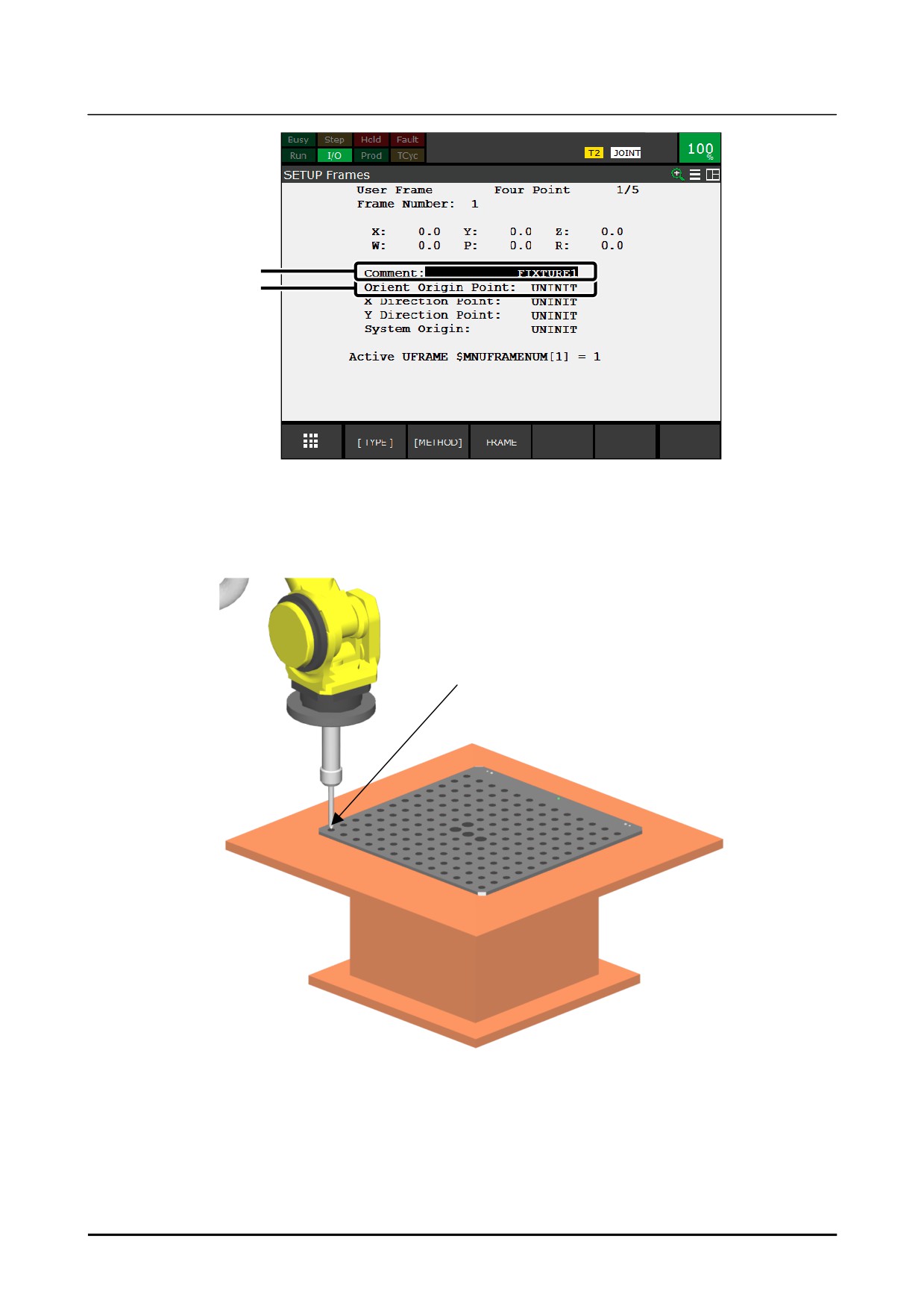
Enter a comment in the [Comment] field as required.
A comment to distinguish this frame from other user frames is recommended.
9
Place the cursor over [Orient Origin Point].
10
Jog the robot and touch up the X direction origin point with the pointer tool.
Orient Origin Point
136
B-83914EN-2/01
Know-How
1. FRAME SETTING
1
12
11
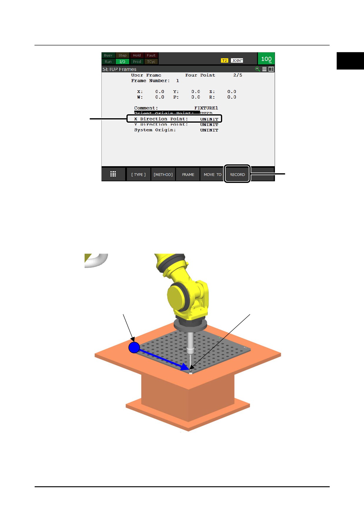
11 While holding down the [SHIFT] key, press F5 [RECORD].
The current position data will be entered as the X-axis origin point.
For the taught [Orient Origin Point], [Used] will appear.
12 Place the cursor over [X Direction Point].
13 Jog the robot and touch up the X direction point of the frame with the pointer tool.
A line drawn between the orient origin point and the touched up X direction point will be the X-axis
of the frame.
Orient Origin Point
X Direction Point
X
B-83914EN-2/01
137
1. FRAME SETTING
Know-How
15
14
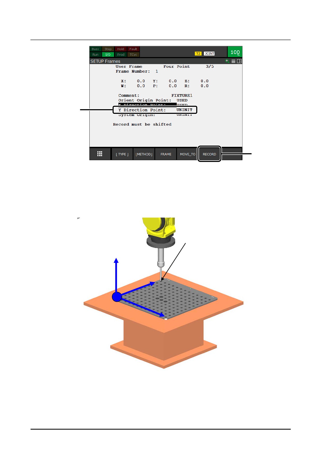
14 While holding down the [SHIFT] key, press F5 [RECORD].
The current position data will be entered as the X direction.
[USED] will be shown for the taught [X Direction Point].
15 Place the cursor over [Y Direction Point].
16 Jog the robot and touch up the Y direction point with the pointer tool.
Touching up the Y-axis direction will determine the X and Y plane of the frame.
Y Direction Point
Z
Y
X
138
B-83914EN-2/01
Know-How
1. FRAME SETTING
1
18
17
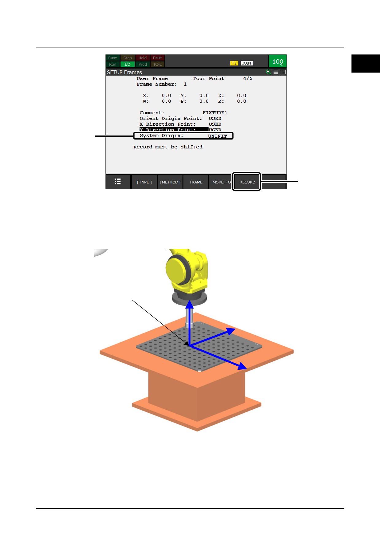
17 While holding down the [SHIFT] key, press F5 [RECORD].
The current position data will be entered as the Y-axis direction.
[USED] will be shown for the taught [Y Direction Point].
18 Place the cursor over [ System Origin].
19 Jog the robot and touch up the orient origin point of the frame with the pointer tool.
System Origin
Z
Y
X
B-83914EN-2/01
139
1. FRAME SETTING
Know-How
20
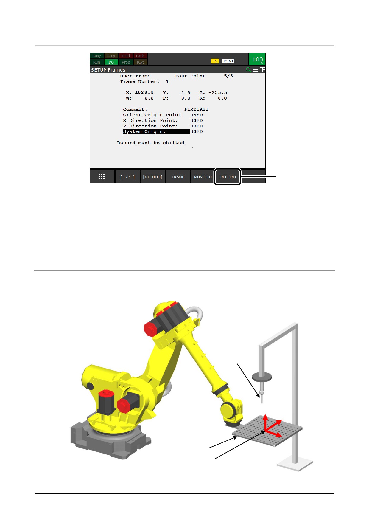
20 While holding down the [SHIFT] key, press F5 [RECORD].
The current position data will be recorded as the orient origin of the frame.
When all the touch-up points are taught, [Used] will be displayed. The user frame will be set.
21 Press the [PREV] key.
The User Frame list screen will appear.
22 Press F5 [RECORD] and enter the frame number.
The user frame that has been set will be set as the currently enabled user frame.
1.1.2
Tool Frame Setting
This subsection is explained a tool frame setting on the calibration grid that the is mounted on the robot
end of arm tooling.
Fixed pointer
Z
Y
X
Calibration grid
Tool frame
Example of tool frame setting with a pointer tool
140
B-83914EN-2/01
Know-How
1. FRAME SETTING
After the pointer for touch-up is secured to a secured stand, select “Tool Frame Setup / Six Point(XY)” or
1
“Tool Frame Setup / Six Point(XZ)”, and teach the six points shown in the figure below by touch-up
operation. The position of fixed pointer is arbitrarily.
System Origin
X Direction
Approach point 1
Approach point 2
Approach point 3
Z
-
axis/Y
-
axis
Six point teaching method touch-up points for a calibration grid
The user tool set using the “Tool Frame Setup / Six Point(XZ)” method is rotated by 90 degrees about the
X-axis with respect to a desired coordinate system. Upon completion of setting the user tool frame by
touch-up operation, manually enter the value of W plus 90.
In the example of this subsection, “Tool Frame Setup / Six Point(XY)” is explained. Make sure that the
calibration grid is fixed securely to the robot end of arm tooling so that it remains in place while the robot
moves. Positioning pins or other appropriate means may be used so that the calibration grid can be
mounted at the same position for each measurement. Moreover, set the tool frame accurately on the
calibration grid. If the accuracy of this frame setting is low, the precision in handling of a workpiece by
the robot is also degraded.
1
On the teach pendant, after selecting the [MENU] key → [Setup], place the cursor over [Frame] and
press the [ENTER] key.
2
Press F3 [Frame].
3
Place the cursor over [Tool] and press the [ENTER] key.
The list screen for tool frames will appear.
B-83914EN-2/01
141
1. FRAME SETTING
Know-How
4
5
4
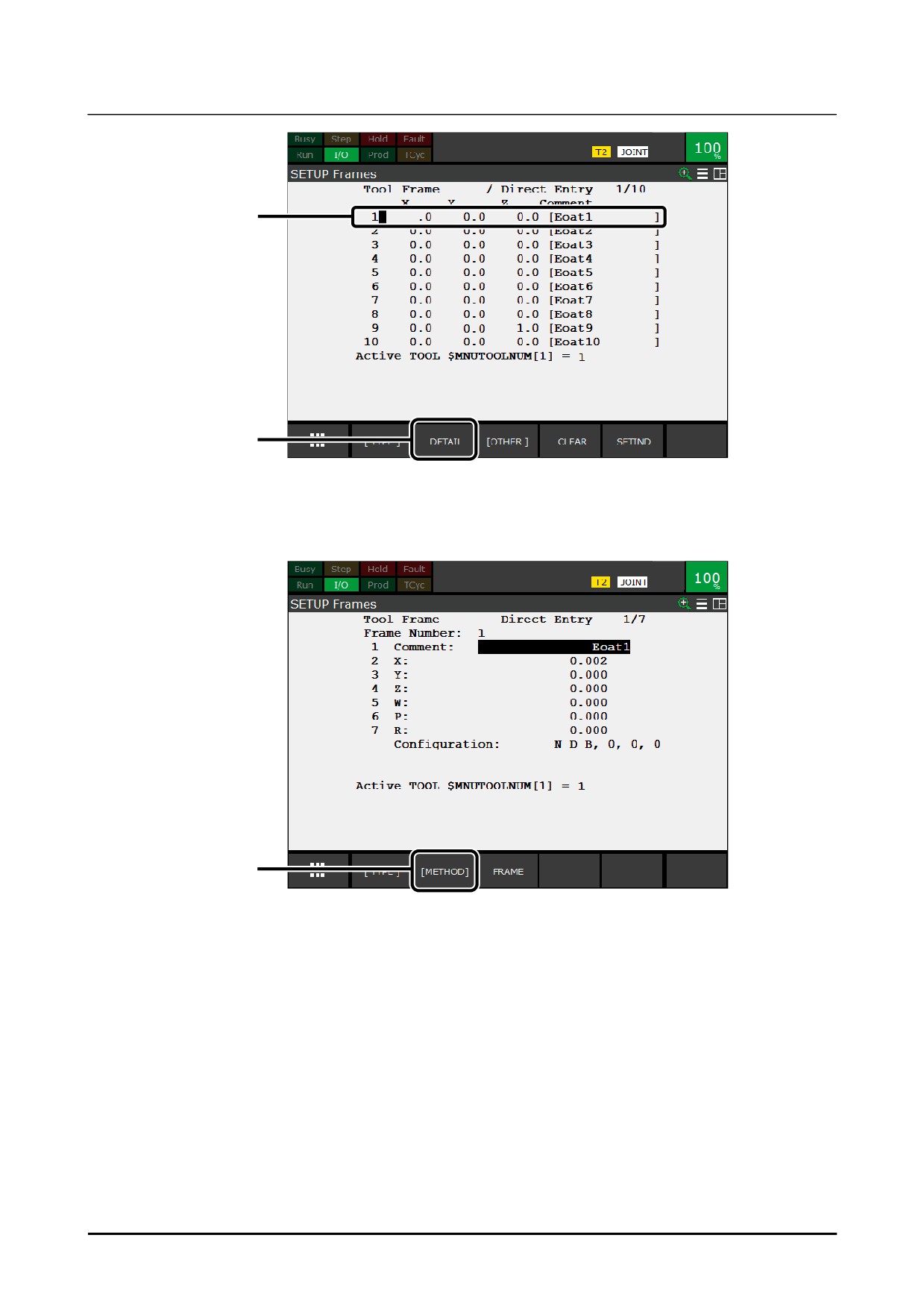
Place the cursor over the line of the tool frame number to set.
5
Press F2 [DETAILS].
The setup screen for the tool frame for the selected frame number will appear.
6
6
Press F2 [METHOD].
7
Place the cursor over [Six Point (XY)] and press the [ENTER] key.
A screen for tool frame setting using six points will appear.
142
B-83914EN-2/01
Know-How
1. FRAME SETTING
1
8
9
8
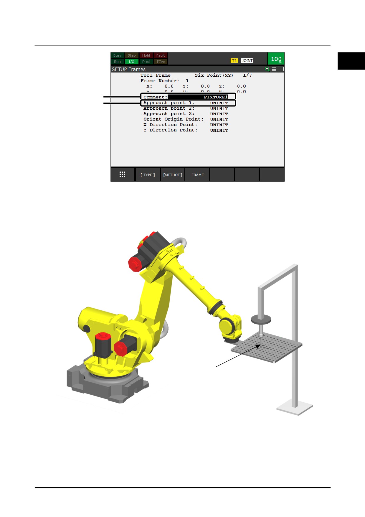
Enter a comment in the [Comment] field as required.
A comment to distinguish this frame from other frames is recommended..
9
Place the cursor over [Approach point 1].
10
Jog the robot and touch up the reference point 1 with the pointer tool.
Approach point 1
Touch-up of approach point 1
B-83914EN-2/01
143
1. FRAME SETTING
Know-How
12
11
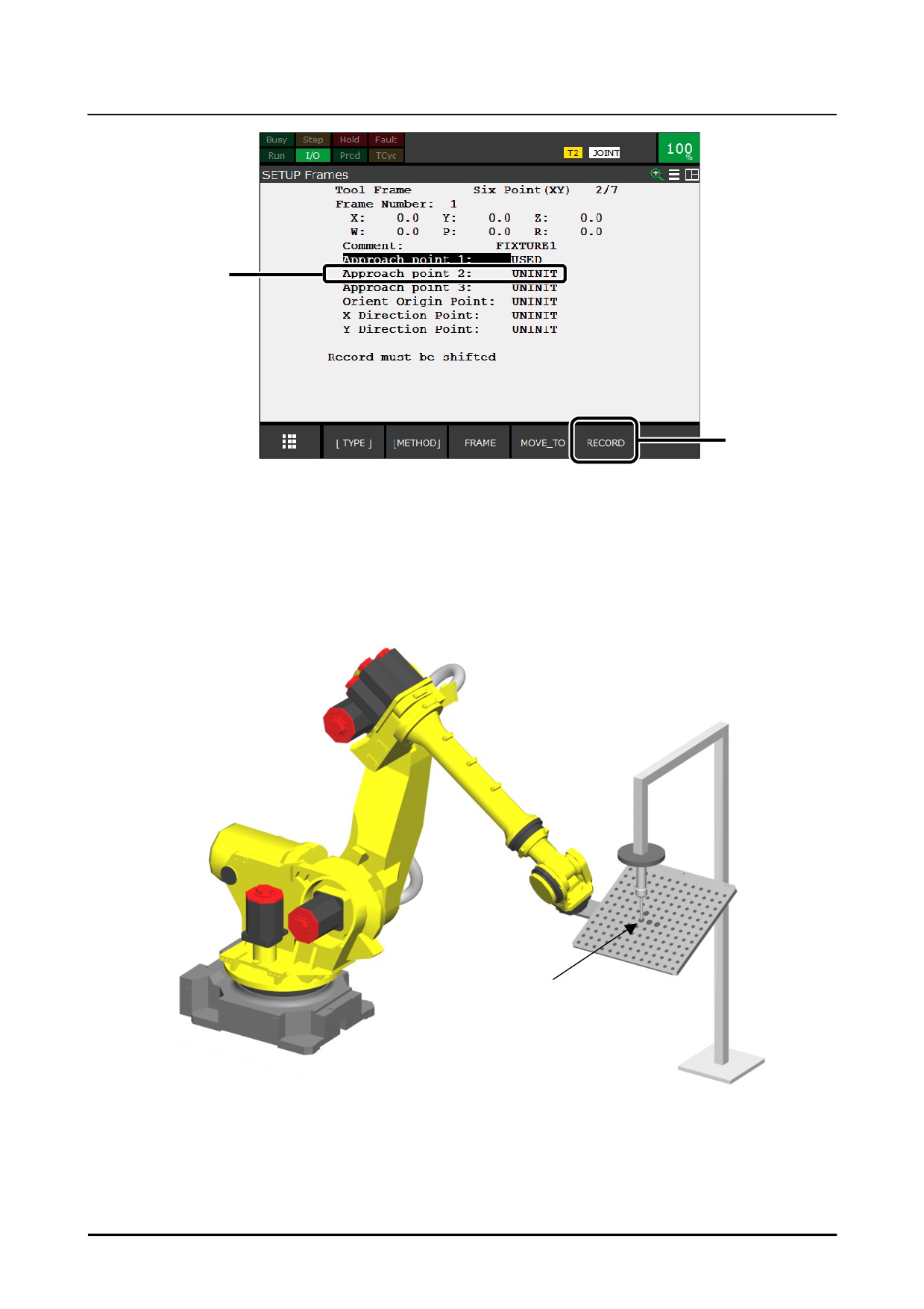
11 While holding down the [SHIFT] key, press F5 [RECORD].
The current value's data will be input as approach point 1.
For the taught [Approach point 1], [Used] will be displayed.
12 Place the cursor over [Approach point 2].
13 Jog the robot and touch up the reference point 2 with the pointer tool.
Touch up the same point as the reference point 1. However, change the robot attitude from that of
the reference point 1.
Approach point 2
Touch-up of approach point 2
144
B-83914EN-2/01
Know-How
1. FRAME SETTING
1
15
14
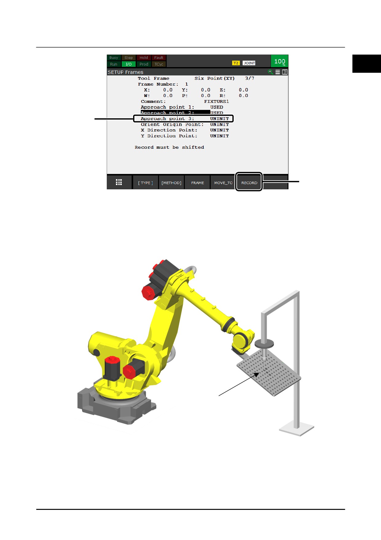
14 Press and hold the [SHIFT] key and press F5 [RECORD] to record the data of current position as the
reference position. As for the [Approach point 2], [USED] is displayed.
15 Move the cursor to the [Approach point 2].
16 Jog the robot and touch up the [Approach point 2] with the fixed pointer. The position of
[Approach point 2] is same position as the approach point 1. However, the posture of approach
point 2 is different from the posture of approach point 1.
Approach point 3
Touch-up of approach point 3
B-83914EN-2/01
145
1. FRAME SETTING
Know-How
18
17
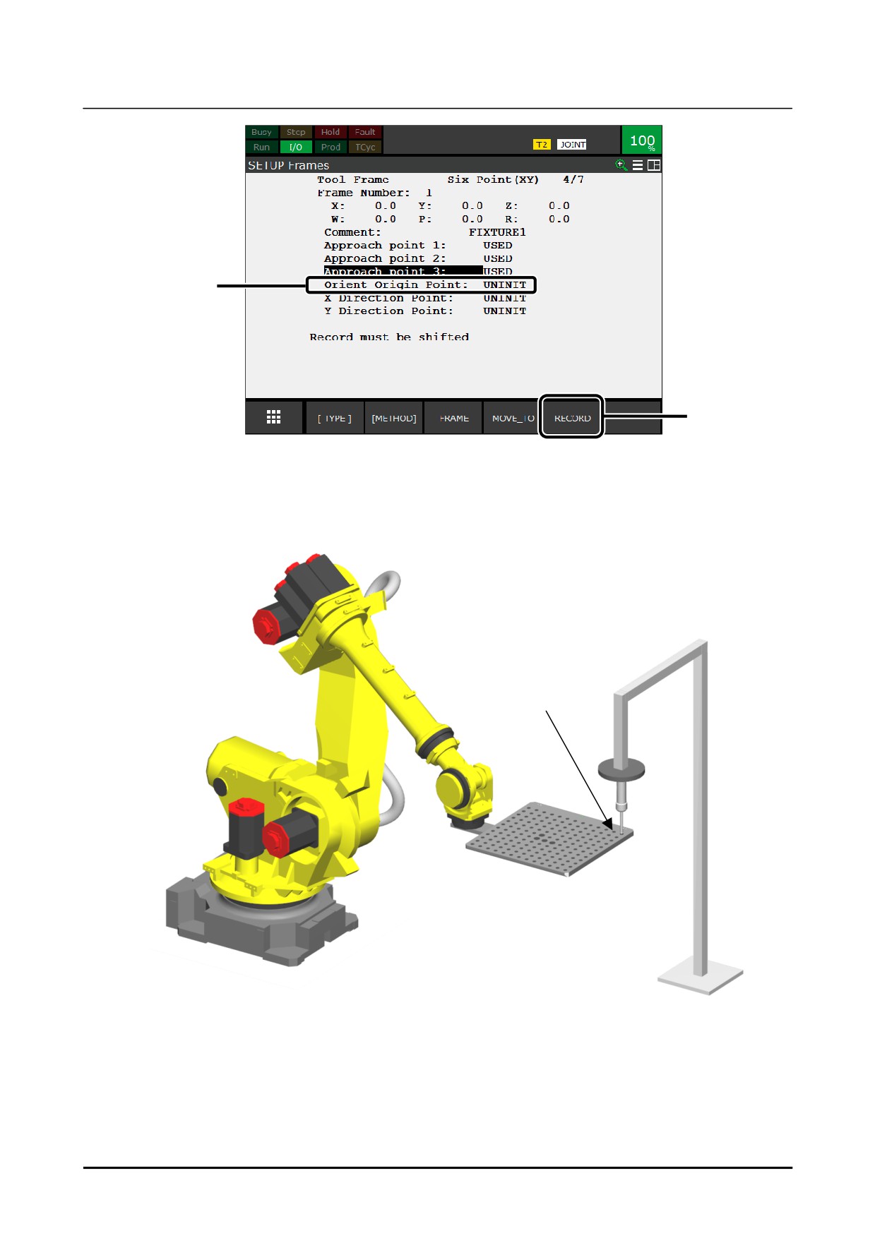
17 Press and hold the [SHIFT] key and press F5 [RECORD] to record the data of current position as the
reference position. As for the taught reference point, [USED]is displayed.
18 Move the cursor to the [Orient Origin Point].
19 Jog the robot and touch up the Orient Origin Point with the fixed pointer.
Orient Origin Point
Touch-up of the point for the Orient Origin Point
146
B-83914EN-2/01
Know-How
1. FRAME SETTING
1
21
20
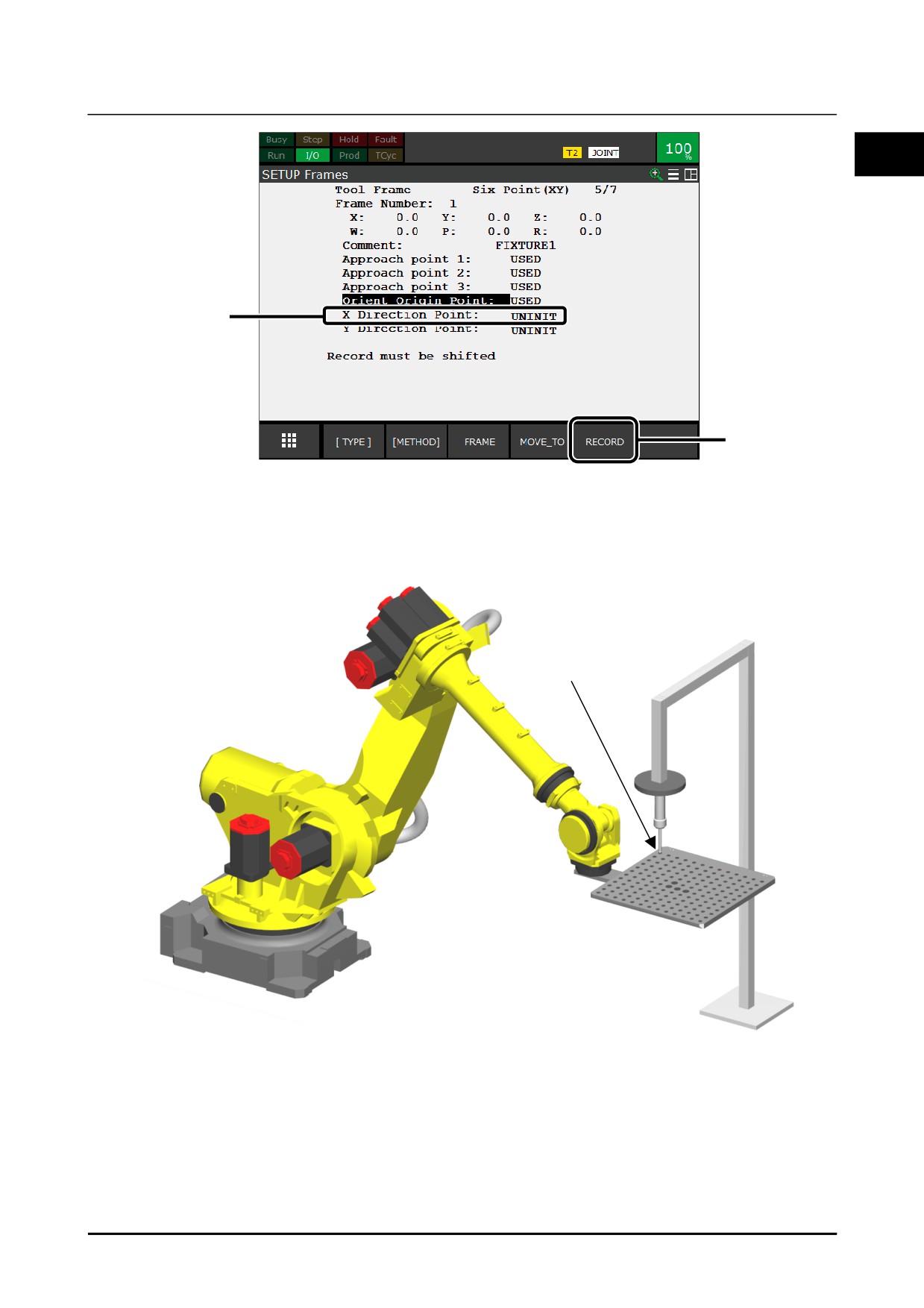
20 Press and hold the SHIFT key and press F5 RECORD to record the data of current position as the
reference position. As for the taught reference point, RECORED is displayed.
21 Move the cursor to the X Direction Point.
22 Jog the robot and touch up the X Direction Point with the fixed pointer.
X Direction Point
Touch-up of X direction point
B-83914EN-2/01
147
1. FRAME SETTING
Know-How
24
23
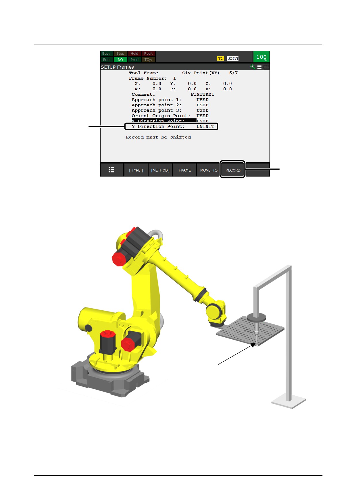
23 Press and hold the SHIFT key and press F5 RECORD to record the data of current position as the
reference position. As for the taught reference point, RECORED is displayed.
24 Move the cursor to the Y Direction Point.
25 Jog the robot and touch up the Y Direction Point with the fixed pointer.
Y Direction Point
Touch-up of Y direction point
148
B-83914EN-2/01
Know-How
1. FRAME SETTING
1
26
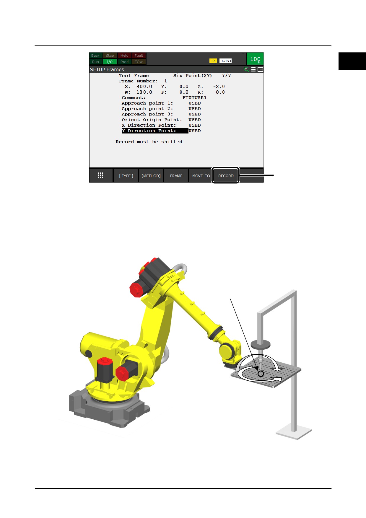
26 Press and hold the SHIFT key and press F5 RECORD to record the data of current position as the
reference position. When all the reference points are taught, USED is displayed. The tool frame
has been set.
27 To display the tool frame list screen, press the PREV key.
28 Check the TCP is set accuracy. Press F5 [SETIND] and enter the frame number.
The tool frame that has been set will be set as the currently enabled tool frame.
29 Jog the robot to move the origin point of the calibration grid close to the tip of the fixed pointer tool.
Center of rotation
Check by moving the origin point of the calibration grid close to tip of fixed pointer tool
B-83914EN-2/01
149
1. FRAME SETTING
Know-How
30 Operate the robot by jog operation around the tool frame, and change the orientation of the
calibration grid (w, p, r). If the TCP is accurate, the tip of the pointer tool will always point toward
the origin point of the calibration grid.
1.2
FRAME SETTING WITH THE GRDI FRAME SSETTING
FUNCTION
Function overview
In the Grid Frame Setting Function, the robot holding the camera or the robot holding calibration grid
automatically moves to change relative position and orientation between the camera and the calibration
grid, and find the grid pattern repeatedly. Finally, the position of the calibration grid frame relative to
the robot base frame or the robot mechanical interface frame (the robot face place) is identified. When
the Grid Frame Setting Function is executed, a frame is set on the calibration grid, as shown in the
following figure.
Y
Origin
X
Example of frame using calibration grid
Compared with the manual touch-up setting method, the function offers a number of merits, including
accurate setting of the frame without requiring user skills, no need for touch-up pointers or to set the TCP
for touch-up setting, and semi-automatic easy-to-do operation.
CAUTION
The Grid Frame Setting Function is usable with 6-axis robots only. The function
cannot be used with 4-axis robots and 5-axis robots.
150
B-83914EN-2/01
Know-How
1. FRAME SETTING
1.2.1
Setting procedure
1
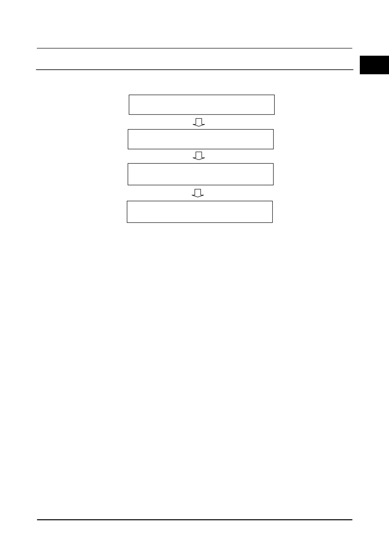
Use the following setup procedure for the Grid Frame Setting Function:
1.
Mounting the calibration grid
2.
Camera data creation and teaching
3.
Setting the parameters
4.
Run Measurement
B-83914EN-2/01
151
1. FRAME SETTING
Know-How
1.2.1.1 Mounting the calibration grid
When the calibration grid is secured to a fixed surface
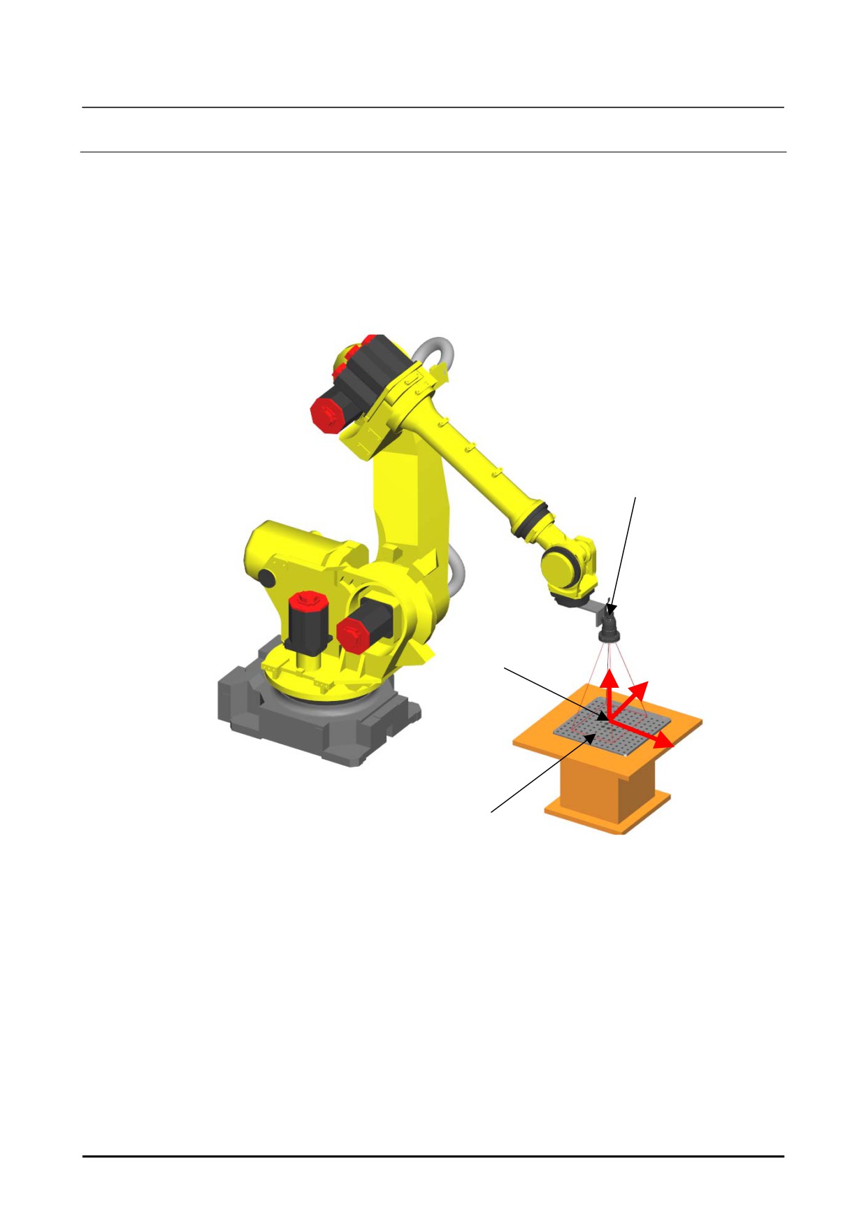
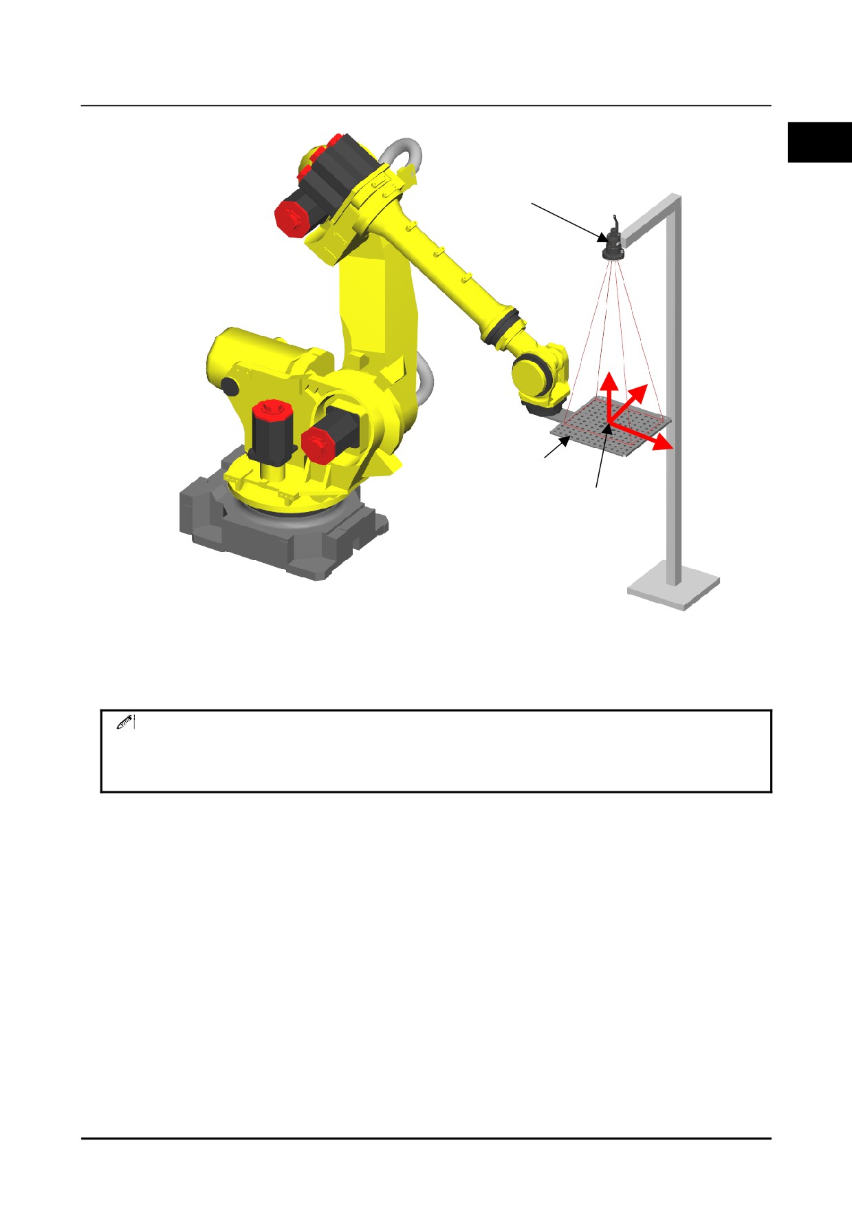
When the calibration grid is secured to fixed surface, a camera mounted on the robot end of arm tooling is
used to measure the position of the calibration grid frame. The Grid Frame Setting Function identifies
the position of the calibration grid frame relative to the robot base frame (world), and sets the results in a
user specified user frame. When use a robot-mounted camera, the Grid Frame Setting Function can be
performed with the camera currently used. When use a fixed camera, prepare another camera for the
Grid Frame Setting Function separately. Then, perform the Grid Frame Setting Function using the
camera attached to the arbitrary positions of the robot end of arm tooling.
Robot mounted-camera
User frame
Calibration grid
Example of a fixed calibration grid
When the calibration grid is mounted on the robot
When the calibration grid is mounted on the robot, a fixed camera is used to measure the position of the
calibration grid frame. The robot moves the calibration grid within the field of view of the fixed camera.
The Grid Frame Setting Function identifies the position of the calibration grid frame relative to the robot
mechanical interface frame (the robot face plate), and the results is written in a user defined user tool.
The Grid Frame Setting Function can be performed with the camera currently used. When there is not
sufficient space to perform Grid Frame Setting Function with the camera currently used, prepare another
fixed camera and Grid Frame Setting Function can be performed.
152
B-83914EN-2/01
Know-How
1. FRAME SETTING
1
Camera
Calibration grid
Tool frame
Example of a calibration grid attached to the robot hand
Make sure that the calibration grid is fixed securely so that it does not move during measurement.
MEMO
To prevent unnecessary circles from being found, check that the calibration grid
is free of dirt and flaws. Spreading a plain sheet in the background is effective.
Also, make sure to cover the printed text on the calibration grid.
B-83914EN-2/01
153
1. FRAME SETTING
Know-How
1.2.1.2 Setting the parameters
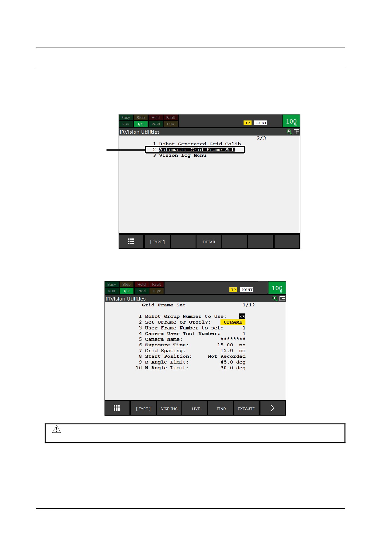
Setup the parameters on [iRVision Utilities] screen of the teach pendant.
1
On the teach pendant, after selecting the [MENU] key → [iRVision], place the cursor over [Vision
Utilities] and press the [ENTER] key.
The iRVision Utilities screen will appear.
2
2
Place the cursor over [Automatic Grid Frame Set] and press the [ENTER] key.
The [Grid Frame Set] screen will appear.
CAUTION
The Grid Frame Set menu cannot be opened in more than one window at a time.
The following items will be displayed on the [Grid Frame Set] screen.
154
B-83914EN-2/01
Know-How
1. FRAME SETTING
[Robot Group Number to Use]
1
Specify the group number of the robot to be used for measurement.
[Set UFrame or UTool?]
Select the frame to be set with the Grid Frame Setting Function - user frame or user tool. When set the
user tool with the calibration grid mounted on the robot, select F4 [UTOOL]. When set the user frame
with the calibration grid installed on a table or other fixed surface, select F5 [UFRAME].
[User Frame Number to set]
Specify the number of the user frame to be set. This will only be displayed if [UFRAME] is selected in
[Set UFrame or UTool?]. The range of specifiable user frame numbers is 1 to 9.
[Tool Frame Number to set]
Specify the number of the user tool to be set. The range of specifiable user tool numbers is 1 to 10.
This will only be displayed if [UTOOL] is selected for [Set UFrame or UTool?].
[Camera User Tool Number]
Specify the number of the user tool for the work space to be used during calculation. The range of
specifiable user tool numbers is 1 to 10. The tool frame set here will be overwritten during measurement
for automatic grid frame set. This can only be set if [User Frame] is selected for [Set UFrame or
UTool?]. The range of specifiable user tool numbers is 1 to 10.
[Camera Name]
Select a camera to use in the measurement. Place the cursor over the line of [Camera Name], then press
F4 [FIND], and a list of cameras will be displayed. By selecting from the list, specify the camera to use
for the measurement.
[Exposure Time]
Specify the exposure time for the camera to capture an image (Shutter speed). The larger the value, the
brighter the images that will be snapped.
Adjust the exposure time so that the black circles of the calibration grid are clearly visible.
[Grid Spacing]
Set the grid spacing of the calibration grid in use.
[Start Position]
Teach the position where measurement is to be started. If the position has been taught already,
[Recorded] will be displayed, and if it hasn't been, [Not Recorded] will be displayed.
In the case of [Not Recorded], measurement cannot be executed. Be sure you always teach the start
position before measurement.
For the procedure to teach the start position, refer to Know-how Edition Subsection 1.2.1.3, "Teaching
Start Position".
[R Angle Limit], [W Angle Limit], [P Angle Limit], [Z Movement Distance Limit]
Set the space for operation of the robot when executing measurement.
When executing measurement, the robot will automatically operate within the region set as the motion
range. Make sure there is a sufficient workspace around the measurement space, so that the robot will
not interfere with devices. The robot generally operates as follows when it is in a state in which the
default settings are set.
•
±100 mm PAN operation to XYZ
B-83914EN-2/01
155
1. FRAME SETTING
Know-How
• Rotates ±45° around the camera's optical axis
• Slope (WP) rotates ±30° from the camera's optical axis at the robot's start position
• Slope (WP) rotates ±30° from the camera's optical axis when facing the calibration grid
If the motion range determined by the default setting cannot be secured, the motion range can be made
smaller by changing the value of each item. However, the accuracy of the frame that will be set will
depend on the motion amount at the time of measurement. If the workspace is made smaller, accuracy
of measurement may decrease, so it is recommended that you execute measurement with a workspace that
is as close to the initial setting as possible.
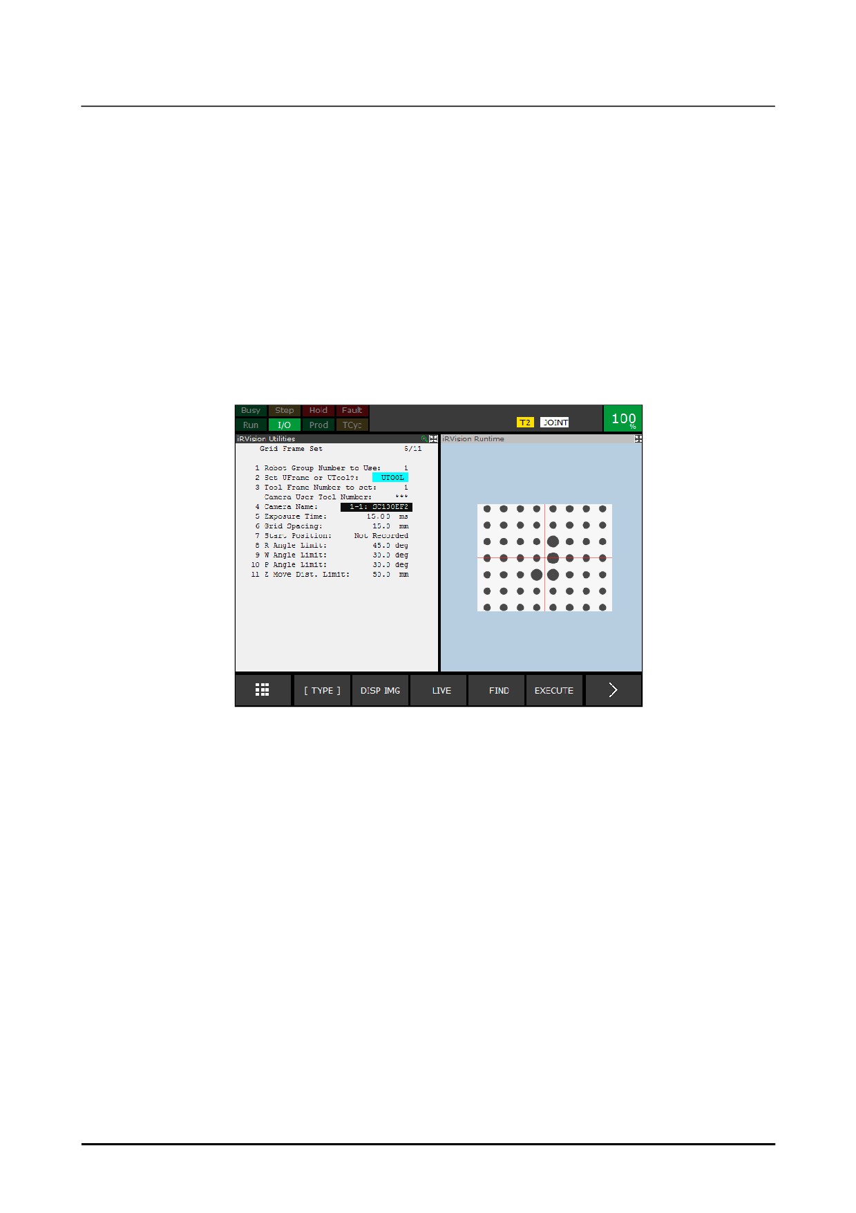
The following function keys will be displayed on the [Automatic Grid Frame Set] screen as common
functions.
F2 [DISP IMG]
The Automatic Grid Frame Set screen and Vision Runtime screen will be displayed as follows.
F3 [LIVE]
A live image for the selected camera will be displayed on the Vision Runtime screen. When a live
image is displayed, it changes to F3 [STOPLIVE] and if F3 [STOPLIVE] is pressed, live image display
will be stopped.
F4 [FIND]
Detect a grid pattern. The detection result will be displayed on the Vision Runtime screen.
F7 [RESET]
The set values will be changed to the initial values.
[Camera Name] and [Start Position] will be returned
to their initial values so that you can set them again.
156
B-83914EN-2/01
Know-How
1. FRAME SETTING
1.2.1.3 Teaching start position
1
Teach the start position using the following procedure.
1
If Vision Runtime is not displayed, press F2 [DISP IMG].
2
Place the cursor over [Start Position].
3
Jog the robot so that the camera's optical axis is approximately perpendicular to the plate surface of
the calibration grid and that all of the four large black circles of the calibration grid are inside the
camera's field of view. The distance between the calibration grid and the camera should be
appropriate for the grid to come into focus, which is, under normal circumstances, roughly the same
as the distance at which camera calibration is performed.
MEMO
For Automatic Grid Frame Set, measurement is performed by panning and
rotating the camera attached to the robot's gripper or the calibration grid. It is
recommended that you set the field of view to something quite large in relation to
the calibration grid, so that the four large black dots will not be outside of the
field of view.
Camera field of view
Camera field of view
4
While holding down the [SHIFT] key, press F4 [RECORD].
The start position will be recorded, and [Start Position] changes to [Recorded].
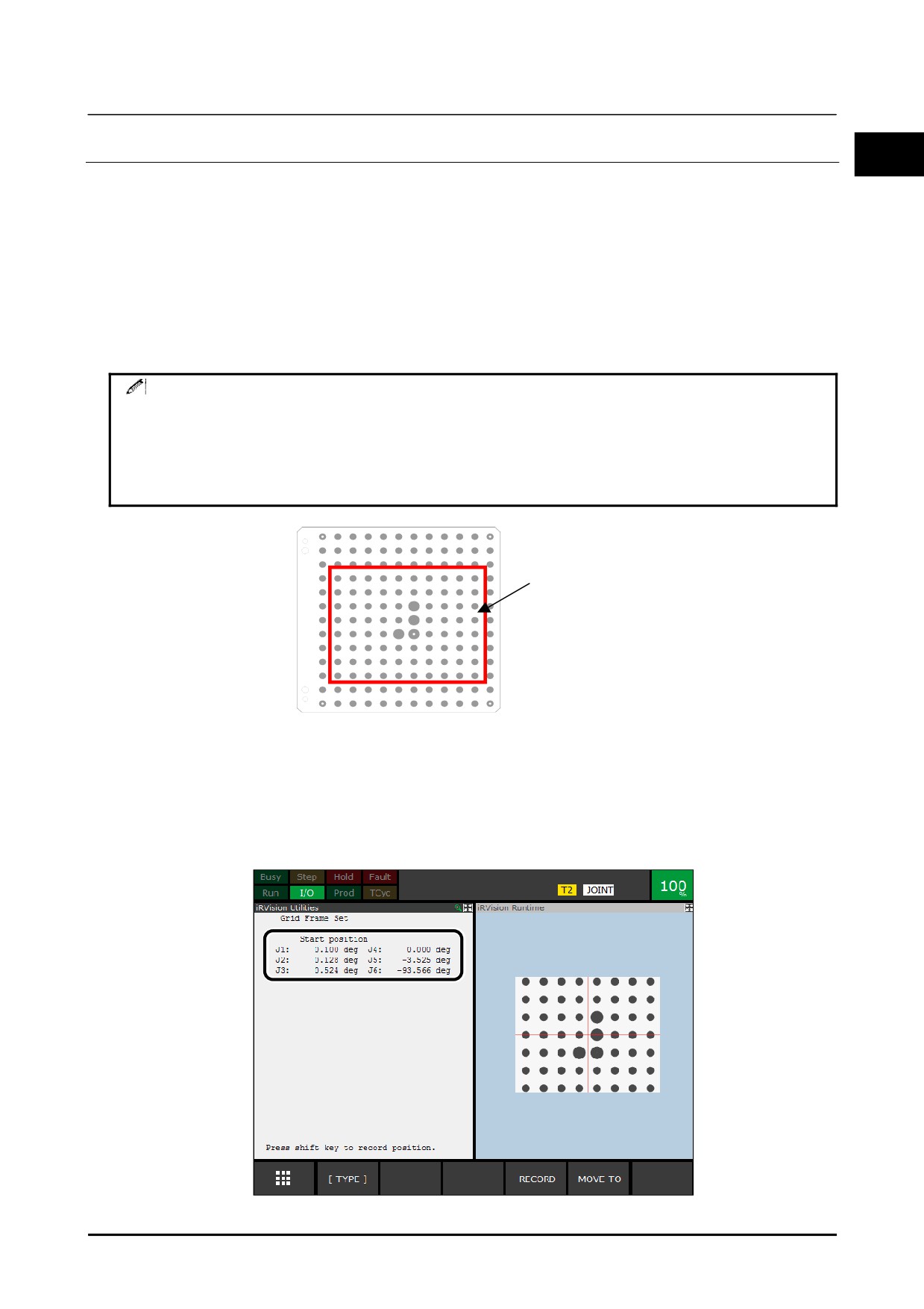
5
To check the trained start position, press F3 POSITION. The value of each axis of the start
position is displayed, as shown below.
B-83914EN-2/01
157
1. FRAME SETTING
Know-How
To return to the previous menu, press PREV.
6
When moving the robot to the taught start position, press F5 [MOVE TO] while pressing the
[SHIFT] key.
1.2.1.4 Run measurement
Perform measurement as follows, using the taught start position as a reference.
1
If Vision Runtime is not displayed, press F2 [DISP IMG].
2
Check the parameter setup on the [Automatic Grid Frame Set] screen.
3
Check that the robot is at the start position.
4
While holding down the [SHIFT] key, press F5 [EXECUTE].
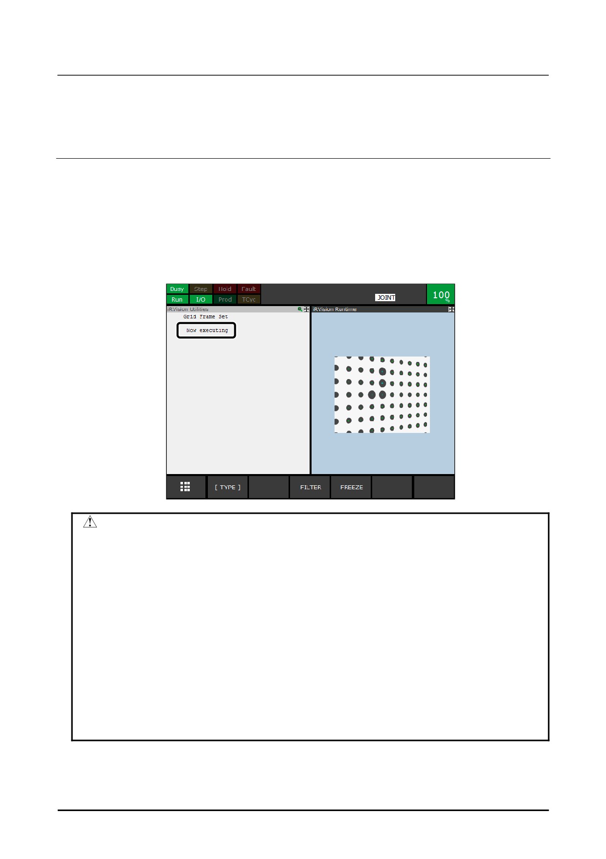
The robot will start the operation, and measurement will be executed. A message saying 'Now
executing' will appear during the operation.
CAUTION
1 The measurement will stop if you release the [SHIFT] key during measurement.
In such cases, redo the measurement. The measurement can be resumed
from where it was stopped.
2 The measurement will stop if you perform an operation that moves to another
screen during measurement, such as pressing the [SELECT] key on the teach
pendant. In such cases, open the [Automatic Grid Frame Set] screen and redo
the measurement. The measurement can be resumed from where it was
stopped.
3 Although the robot will perform the decided motion to some extent, depending on
the settings, it is possible that it will move with an unexpected motion range.
When executing measurement, check that the setup of parameters is correct,
and be careful to lower the override so that the robot will not interfere with
devices.
4 The robot may not be able to operate if other programs are in a paused state.
In such cases, press the [FCTN] key and end the programs.
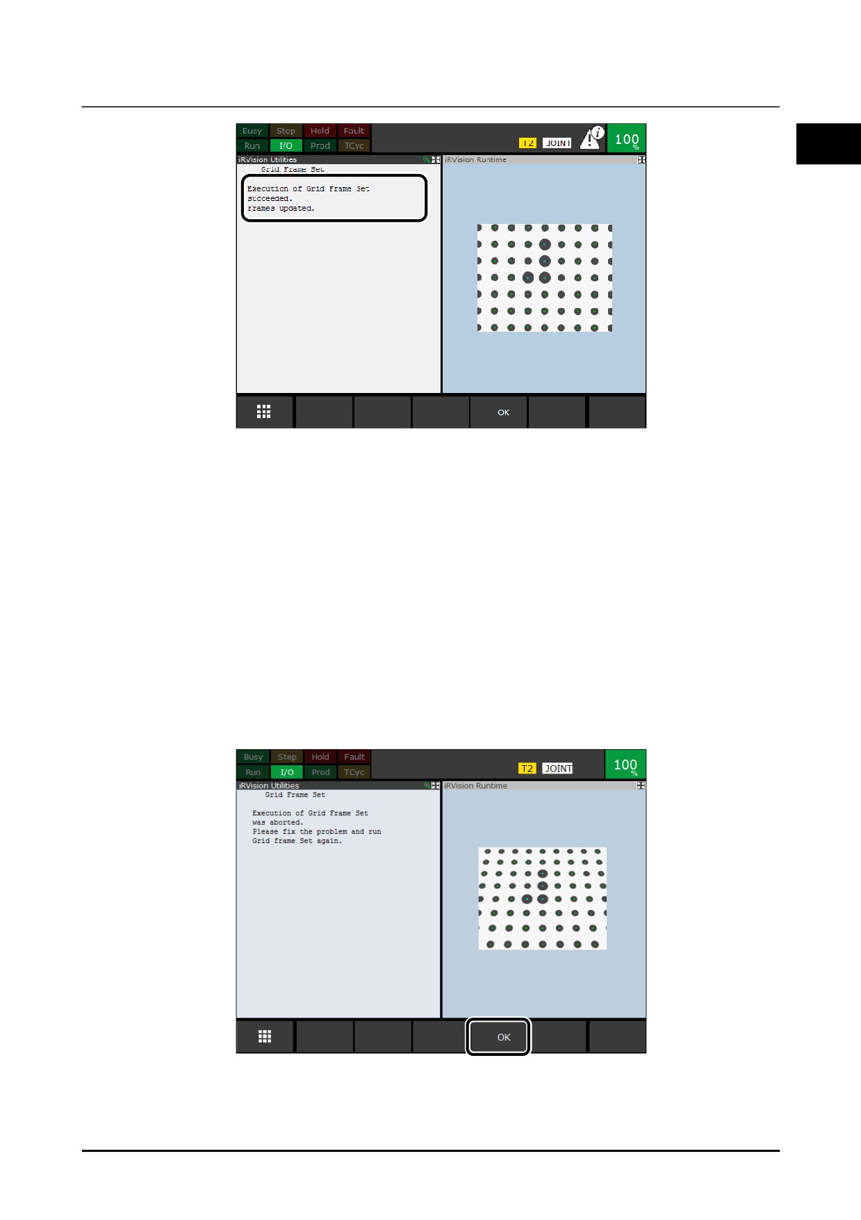
When the measurement is successfully completed, a menu like the one shown below appears. The
robot stops after moving to a position where the camera directly faces the calibration grid and the
origin of the calibration grid comes to the center of the image.
158
B-83914EN-2/01
Know-How
1. FRAME SETTING
1
5
If you press F4 [OK] is pressed, you will return to the Automatic Grid Frame Set screen.
Measurement check
The grid frame will be set depending on the measurement. The set frame can be checked using the
following procedure.
1
Set the manual feed frame as the frame for automatic grid frame set.
For a tool frame, press the [COORD] key and switch to [Tool].
For a user frame, press the [COORD] key to switch to [User], and specify the tool frame number that
was specified in [Camera User Tool] in [Tool] under the jog menu, using the number keys.
2
Press F3 [LIVE] to start the display of a live image, and move the robot by jog operation around the
WPR of the selected tool frame. There will be no problem unless the center position of the grid
pattern is significantly far from the center line of the image.
In the event of failure to measure
If measurement fails, the following message will appear.
If F4 [OK] is pressed, the screen will return to the original screen.
After changing the setup parameters, measurement can be redone by pressing F5 [EXECUTE] while
holding down the [SHIFT] key.
B-83914EN-2/01
159
2. CAMERA DATA SETTING
Know-How
2 CAMERA DATA SETTING
This chapter explains the settings for camera data.
Create camera data and perform camera setup and calibration. Camera calibration is the work of setting
where the camera is installed as seen from the robot. Complete calibration before teaching a vision
process. There are three methods to calibrate a camera. This chapter explains them using the
following structure.
• Know-how Edition Section 2.1, "GRID PATTERN CALIBRATION WITH A FIXED CAMERA".
• Know-how Edition Section 2.2, "GRID PATTERN CALIBRATION WITH A ROBOT-MOUNTED
CAMERA".
• Know-how Edition Section 2.3, "ROBOT-GENERATED GRID CALIBRATION".
2.1
GRID PATTERN CALIBRATION WITH A FIXED CAMERA
Grid pattern calibration is a general-purpose calibration method for cameras that uses a special jig called a
calibration grid. When using grid pattern calibration, prepare a calibration grid in advance. Usually,
prepare a calibration grid which is the bigger than a field of view. A standard calibration grid is
available from FANUC in several sizes. It is strongly recommended that you order a calibration grid as
well as a camera and lens.
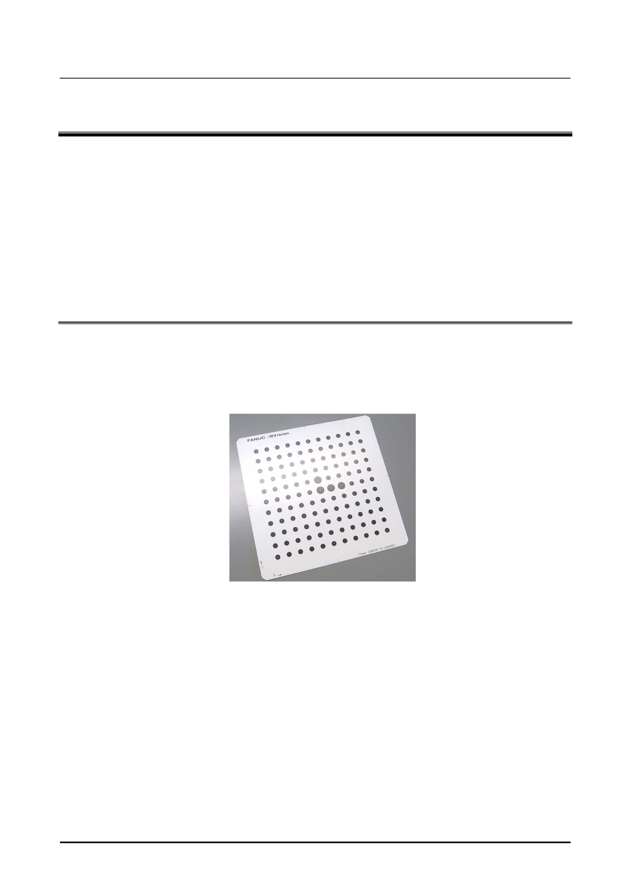
It is not necessary to detect all the dots on the calibration grid. There are 11×11 dots in the standard
calibration grid of FANUC. If 7×7 dots are detected, the camera calibration is performed with sufficient
accuracy.
(The four big dots need to be detected.) In order to show all the dots in field of view, it is
not necessary to prepare a small calibration grid. In order to perform a calibration with accuracy
sufficient to the edge of the field of view, even if the number of detectable dots became fewer, prepare the
bigger calibration grid than a field of view.
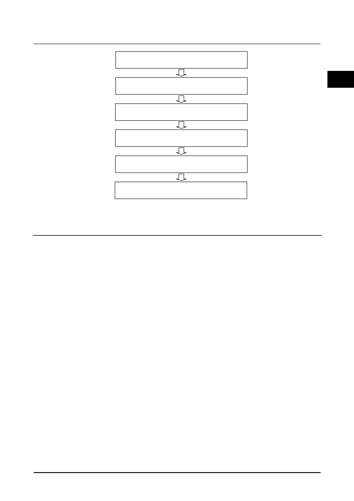
Use the following setup procedure for 'GRID PATTERN CALIBRATION WITH A FIXED CAMERA':
160
B-83914EN-2/01
Know-How
2. CAMERA DATA SETTING
1
Application Frame Setting
2
2
Camera Data Creation
3
Camera Setup
4
Calibration
5
Checking Calibration Point
6
Checking Calibration Result
For a robot system with multiple cameras, create camera data for each camera and perform calibration.
2.1.1
Application Frame Setting
Select a frame for the robot that will be the reference for calibration. Perform camera calibration using
the selected frame as the reference.
User frame [0: World frame] is selected as the default setting. In most cases, it does not need to be
changed. However, in the following cases, set up a user frame and perform calibration using that user
frame number as the application frame.
• In cases where the camera is attached to a robot other than the robot to be offset
• In cases where the calibration grid is attached to a robot other than the robot to be offset
• In cases where multiple robots are to be compensated using the same offset
Also, in cases like the above, it is necessary to carry out communication between robot controllers.
iRVision performs this communication when it is necessary, and for this, an interface function called
'ROS Interface Packet over Ethernet (RIPE)' is used internally. For robot systems to which the above
cases apply, refer to "12 ROS Interface Packet over Ethernet
(RIPE)" in "R-30iA/R-30iA
Mate/R-30iB/R-30iB Mate CONTROLLER Ethernet Function B-82974EN OPERATOR’S MANUAL"
when setting up the RIPE functions.
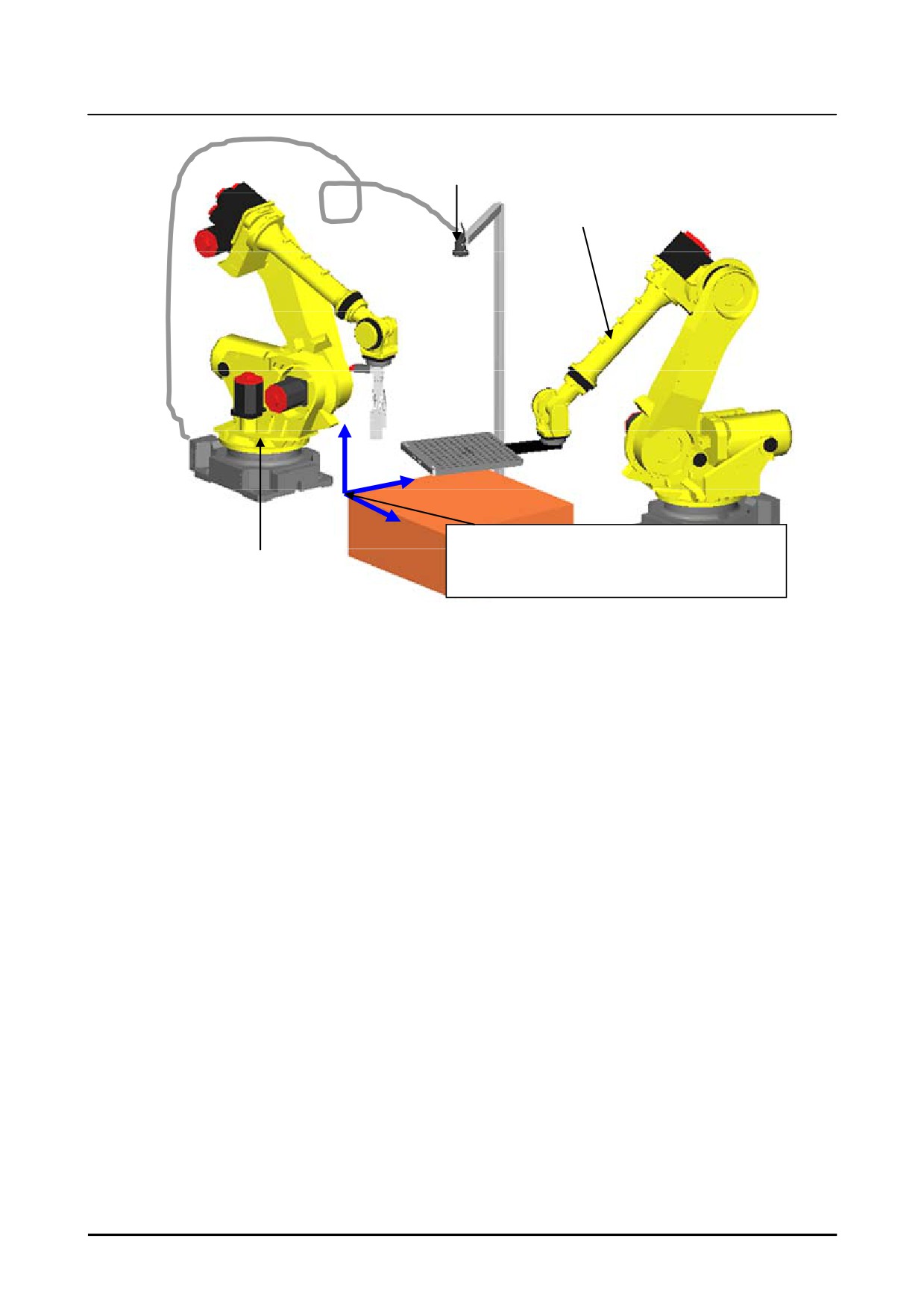
The figure below is an example of a situation in which the calibration grid is attached to a robot other
than the robot to be offset. When a camera is installed on the Robot 1 and a calibration grid is installed
on the Robot 2, set a common user frame for both robots, and use the frame as the application frame.
Also make the user frame number common.
B-83914EN-2/01
161
2. CAMERA DATA SETTING
Know-How
Camera
Robot with a calibration grid
(Robot 2)
Z
Y
X
Common user frame= Application frame
Robot with a camera
(Set the same application frame number for each robot)
(Robot 1)
Example of a situation in which the calibration grid is attached to a robot other than the robot to be offset
For information on user frame settings, refer to Know-how Edition Section 1, "FRAME SETTING".
162
B-83914EN-2/01