FANUC R-30iB Plus CONTROLLER, iRVision 2D Camera Application. OPERATOR'S MANUAL - page 7
Know-How
2. CAMERA DATA SETTING
2.1.2
Camera Data Creation
Create camera data for the 2D camera and set the camera type, method for camera installation, etc.
2
For details on the creation of vision tools, including camera data, refer to Setup Edition Subsection 1.3.1.1,
"Create" in "R-30iB Plus CONTROLLER iRVision OPERATOR’S MANUAL (Reference) B-83914EN".
2.1.3
Camera Setup
Set the camera to use and the type of camera calibration for the camera data that has been created.
1
On the vision data list screen, click the camera data that has been created.
2
Click [Camera] in the navigation area.
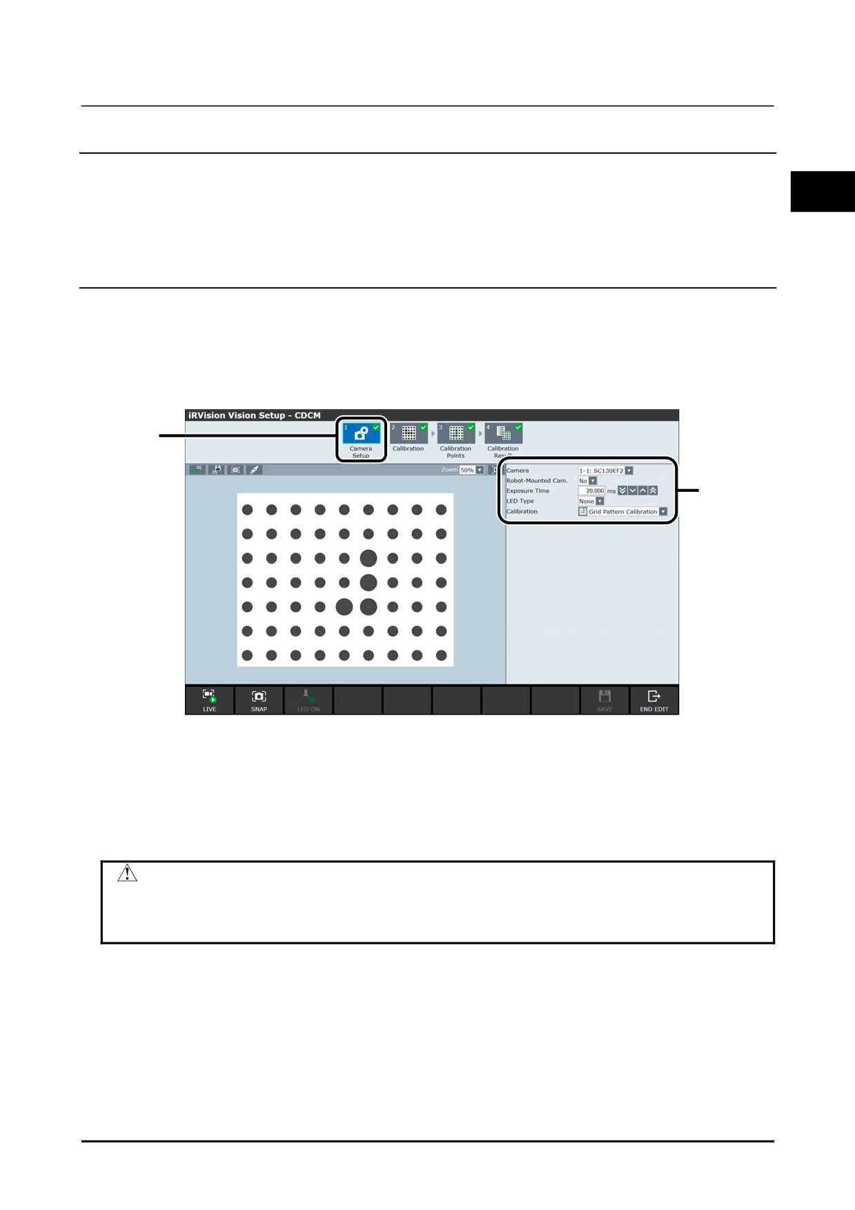
A screen like the following one will appear.
2
3, 4
3 Set the camera to use, the method for camera installation, the exposure time, the presence/absence of
LED lighting, etc.
When use a fixed camera, select [No] for [Robot-Mounted Cam.].
4
Select [Grid Pattern Calibration] for [Calibration].
5
Adjust the diaphragm and focus of the lens. If you click [LIVE], a live image will be displayed in
the image view. Make adjustments while looking at the live image.
CAUTION
Adjust the diaphragm and focus of the lens before camera calibration. If the
diaphragm and focus are readjusted, camera calibration needs to be performed
again.
B-83914EN-2/01
163
2. CAMERA DATA SETTING
Know-How
2.1.4
Calibration
Detect the grid pattern and perform camera calibration. The method for calibration varies depending on
where the calibration grid is installed.
When using a fixed installation for the calibration grid, refer to Know-how Edition Subsection 2.1.4.1,
"For fixed installation".
When installing the calibration grid on the robot's gripper, refer to Know-how Edition Subsection 2.1.4.2,
"For robot-mounted installation".
2.1.4.1 For fixed installation
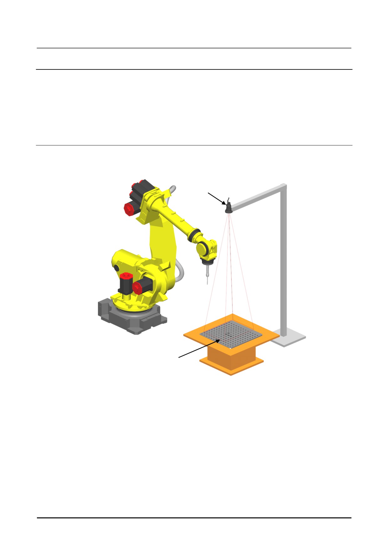
When using a fixed installation for the calibration grid, perform calibration using one plane as shown in
the figure below.
Camera
Calibration grid
Example of using a fixed installation for the calibration grid
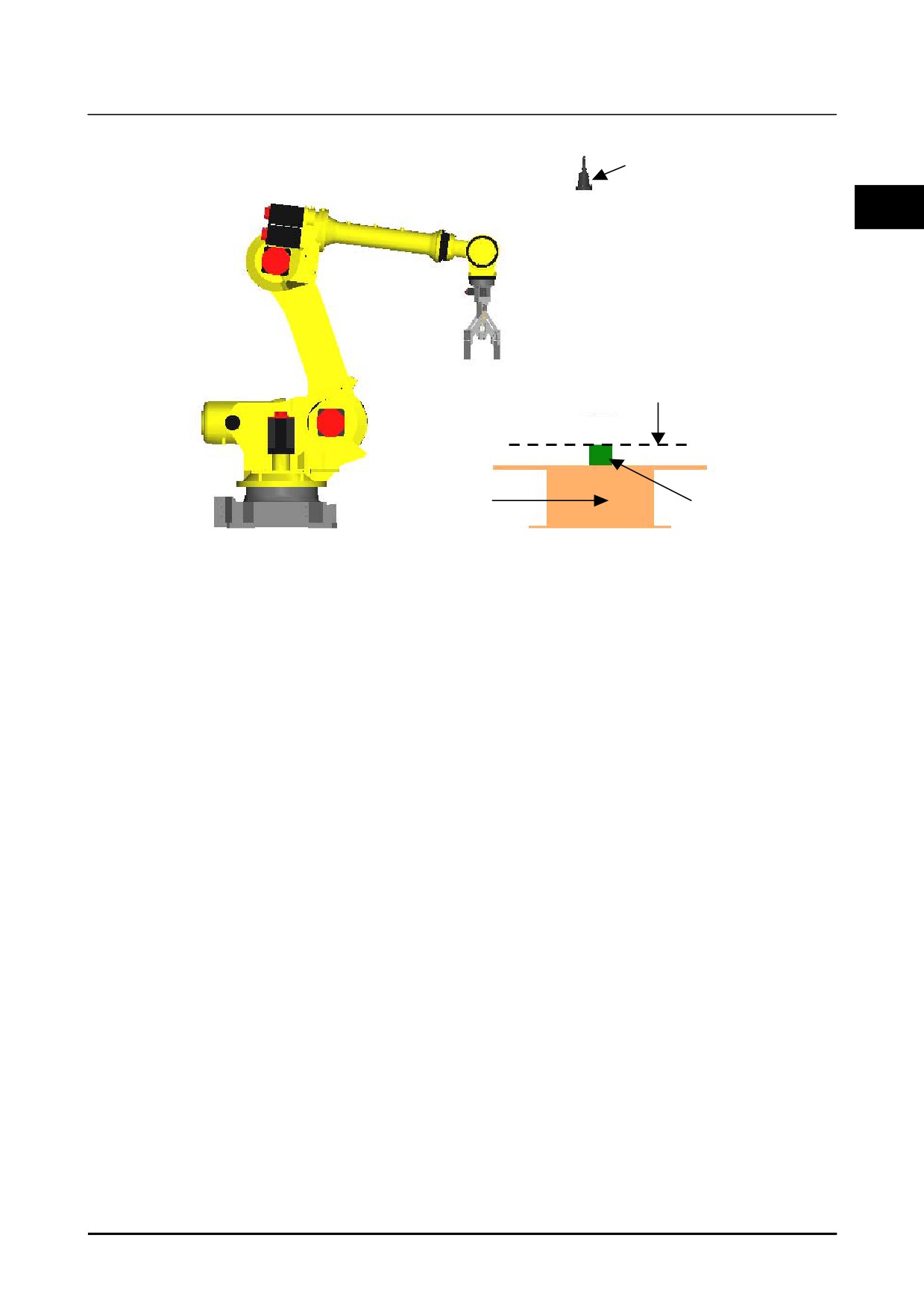
Also, when using a fixed installation for the calibration grid, it is recommended that you install the
calibration grid near the workpiece detection plane. As shown in the figure below, it is recommended
that you install the calibration grid at a position where the distance between the camera and the workpiece
detection plane is the same as the distance between the camera and the calibration grid.
164
B-83914EN-2/01
Know-How
2. CAMERA DATA SETTING
Camera
2
Workpiece measurement plane
Table
Workpiece
Installation plane of the calibration grid and workpiece detection plane
In the frame, set the information that says where the calibration grid is installed. In cases where
calibration is performed with the calibration grid fixed to a table, etc., set the installation information for
the calibration grid in a user frame with an arbitrary number. After setting the calibration grid position
in the user frame, do not move the calibration grid until calibration is complete. There are two methods
for setting a user frame: a method that uses a pointer tool, and a method that uses automatic grid frame set.
For details on setting using touch-up, refer to Know-how Edition Subsection 1.1.1, "User Frame Setting".
For details on setting using automatic grid frame set, refer to Know-how Edition Section 1.2, "FRAME
SETTING WITH THE GRID FRAME SETTING FUNCTION".
B-83914EN-2/01
165

2. CAMERA DATA SETTING
Know-How
Calibration Setting Procedure
Calibration setting for when using a fixed installation for the calibration grid is as follows.
1
Select [Calibration] in the navigation area.
The grid pattern calibration setup screen will appear.
1
2
3
4
5
6
7
8
9
11
2 From the [Application Frame] drop-down box, select a frame for the robot that will be the reference
for calibration.
Specify the number of the user frame set in Know-how Edition Subsection 2.1.1, "Application
Frame Setting".
3
From the [Grid Spacing] drop-down box, select the grid spacing for the calibration grid.
4
From the [Number of Planes] drop-down box, select [1].
When using a fixed installation for the calibration grid, perform calibration using one plane.
5
From the [Robot-Held Cal. Grid] drop-down box, select [No].
6
From the [Cal. Grid Frame] drop-down box, select the number of the user frame in which the
calibration grid installation information was recorded.
MEMO
Note that the frame for [Cal. Grid Frame] is different from the [Application Frame]
or the [Offset Frame] setting.
166
B-83914EN-2/01
Know-How
2. CAMERA DATA SETTING
7
From the [Projection] drop-down box, select the projection method.
8
From the [Camera Distance] drop-down box, select [Override Focal Distance] and enter a nominal
focal distance value for the lens in the text box.
If calibration was performed using one plane by installing the grid pattern perpendicular to the
2
camera's optical axis, the correct focal distance cannot be calculated in principle, so set the focal
distance of the lens by entering it manually after the calibration grid has been detected. For
example, if the focal distance of the lens being used is 12 mm, enter '12.0'.
9
Click the [Set] button for [Fixture Position Status].
The position and the manner in which the calibration grid is placed relative to the application frame
is calculated and recorded.
10 Click [SNAP] and record the image of the calibration grid.
11 Click the [Find] button for [1st Plane].
For details on the settings after finding an image, refer to Know-how Edition Subsection 2.1.5,
"Checking Calibration Point" and Know-how Edition Subsection 2.1.6, "Checking Calibration
Result".
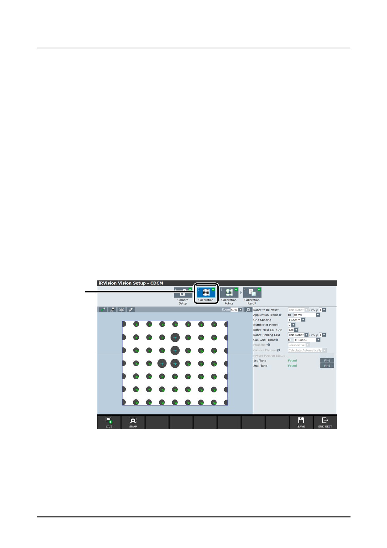
2.1.4.2 For robot-mounted installation
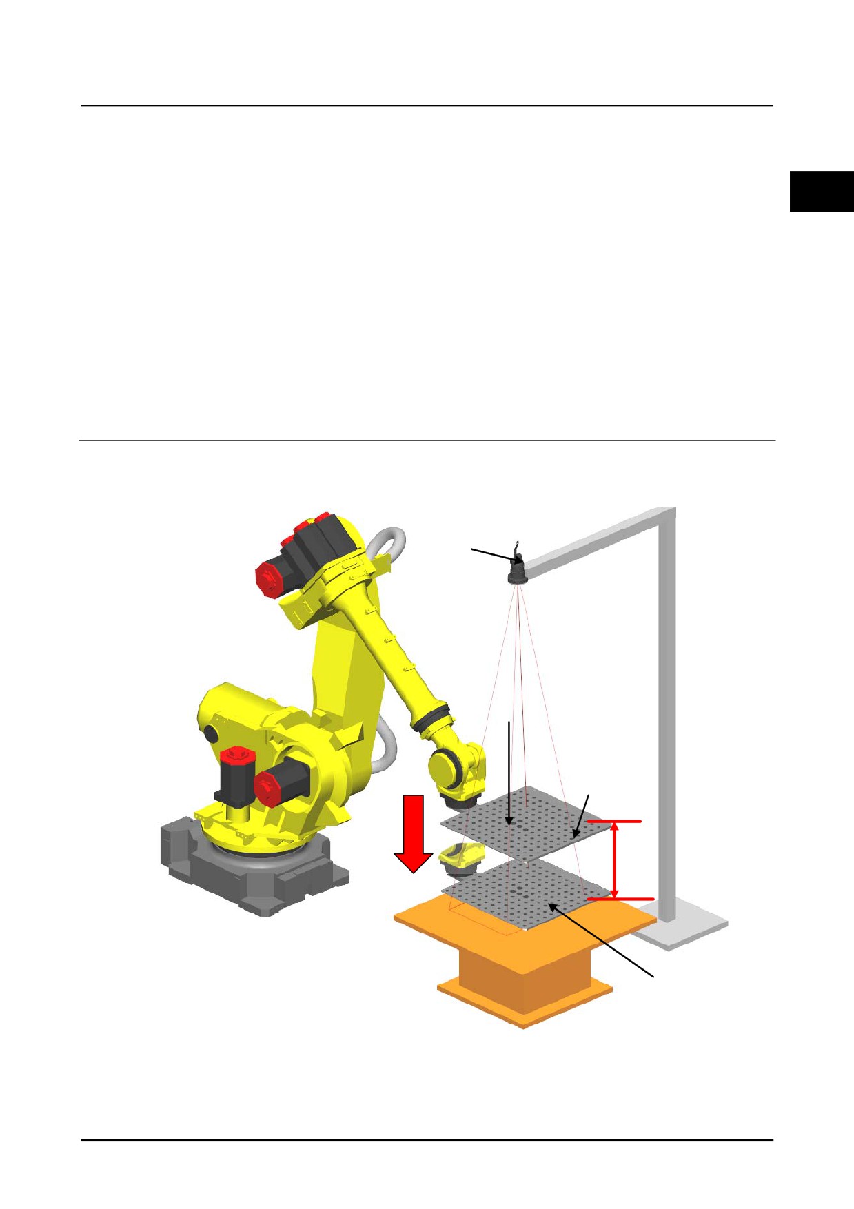
When installing the calibration grid on the robot's gripper, perform calibration using two planes by
moving the robot vertically as shown in the figure below.
Camera
Calibration grid
1st detection
100mm to 50mm
2nd detection
Example of calibration using two planes when installing a calibration grid on the robot's gripper
• In the 2D Single-view Vision Process or 2D Multi-view Vision Process, the up/down distance for
two-plane calibration should be 100 to 150 mm. It is recommended that the distance between the
B-83914EN-2/01
167
2. CAMERA DATA SETTING
Know-How
camera and the calibration grid for one of the planes is the same as the distance between the camera
and the workpiece.
• In the Depalletizing Vision Process, it is recommended that the up/down distance for two-plane
calibration be set to a value that covers the upper and lower ends of the workpiece in the pallet.
• In the 3D Tri-View Vision Process, perform detection by bringing calibration surface 1 as close as
possible to the detection target. In addition, the up/down distance for two-plane calibration should
be 100 to 150 mm.
Find the grid pattern at two different heights. When moving the calibration grid up and down, jog the
robot without changing the calibration grid posture. Make sure that the calibration grid is fixed securely
to the robot end of arm tooling so that it remains in place while the robot moves. It is recommended that
positioning pins or other appropriate means may be used so that the calibration grid can be mounted at the
same position.
For robot-mounted installation, set the installation information for the calibration grid in a tool frame with
an arbitrary number. There are two methods for setting a tool frame: a method that uses a pointer tool,
and a method that uses automatic grid frame set. However, it is recommended that you use automatic
grid frame set. For details on setting using touch-up, refer to Know-how Edition Subsection 1.1.2, "Tool
Frame". For details on setting using automatic grid frame set, refer to Know-how Edition Section 1.2,
"FRAME SETTING WITH THE GRID FRAME SETTING FUNCTION".
Calibration Setting Procedure
Calibration setting for when installing the calibration grid on the robot's gripper is as follows.
1
Select [Calibration] in the navigation area.
The grid pattern calibration setup screen will appear.
1
168
B-83914EN-2/01
Know-How
2. CAMERA DATA SETTING
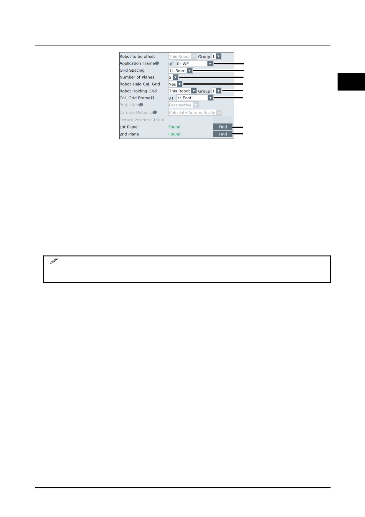
2
3
2
4
5
6
7
8
9
2
From the [Application Frame] drop-down box, select a frame for the robot that will be the reference
for calibration.
Specify the number of the user frame set in Know-how Edition Subsection 2.1.1, "Application
Frame Setting".
3
From the [Grid Spacing] drop-down box, select the grid spacing for the calibration grid.
4
From the [Number of Planes] drop-down box, select [2].
When installing the calibration grid on the robot's gripper, perform calibration using two planes.
5
From the [Robot-Held Cal. Grid] drop-down box, select [Yes].
6
From the [Robot Holding Grid] drop-down box, select the name of the robot controller for the robot
with the calibration grid attached to it, and the motion group number.
7
From the [Cal. Grid Frame] drop-down box, select the number of the tool frame in which the
calibration grid installation information was recorded.
In the tool frame, set the information for where the calibration grid is installed.
MEMO
Note that the frame for [Cal. Grid Frame] is different from the [Application Frame]
or the [Offset Frame] setting.
8
Detect the 1st Plane. Move the calibration grid until it is an appropriate distance from the camera,
and after clicking [SNAP], click the [Find] button for [1st Plane].
9
Detect the 2nd Plane. Change the distance between the calibration grid and the camera, and after
clicking [SNAP], click the [FIND] button for [2nd Plane].
For details on the settings after finding an image, refer to Know-how Edition Subsection 2.1.5,
"Checking Calibration Point" and Know-how Edition Subsection 2.1.6, "Checking Calibration
Result".
B-83914EN-2/01
169
2. CAMERA DATA SETTING
Know-How
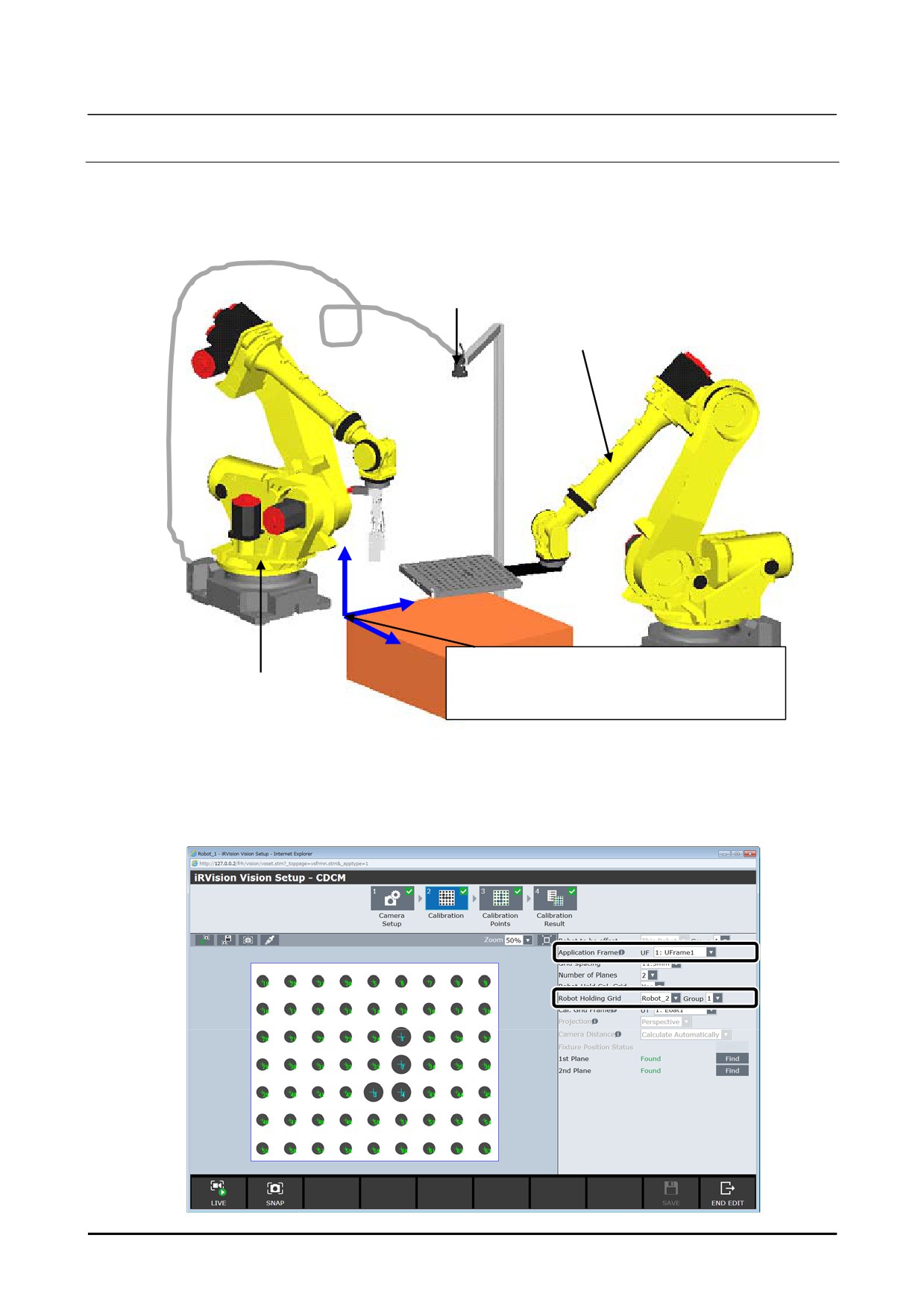
2.1.4.3 When two or more robots are used
If the robot that has a camera attached to it and the robot that has a calibration grid attached to it are
different as shown in the figure below, for the [Robot Holding Grid], select the robot controller for the
robot with the calibration grid attached to it on the teaching screen for calibration.
Camera
Robot with a calibration grid
Z
Y
X
Common user frame= Application frame
Robot with a camera
(Set the same application frame number for each robot)
Example of a situation in which the calibration grid is attached to a robot other than the robot to be offset
The calibration settings for when two or more robots are used are almost the same as the settings for when
installing the calibration grid on the robot's gripper, but the following points are different.
170
B-83914EN-2/01
Know-How
2. CAMERA DATA SETTING
• From the [Application Frame] drop-down box, select a frame for the robot that will be the reference
for calibration. Specify the same user frame number for the two robots.
• From the [Robot Holding Grid] drop-down box, select the name of the robot controller for the robot
with the calibration grid attached to it, and the motion group number.
2
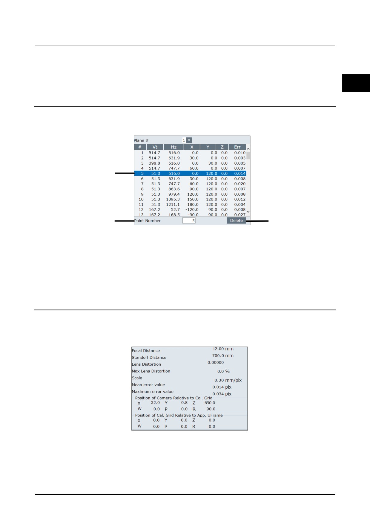
2.1.5
Checking Calibration Point
Check the calibration point found in Know-how Edition Subsection 2.1.4, [Calibration].
If you click [Calibration Points] in the navigation area, the calibration points screen will appear.
1
1
2
If there are points found other than the dot positions of the calibration grid, delete the irrelevant found
points using the following procedure.
1
Select an irrelevant found point from the found point list, or enter a found point number in the [Point
Number] text box.
2
Click the [DELETE] button.
The irrelevant found point will be deleted.
2.1.6
Checking Calibration Result
Check the calculated calibration data.
If you click [Calibration Result] in the navigation area, a calibration result screen like the following one
will appear.
[Scale] indicates how many mm one pixel on an image is equivalent to. It can be calculated by dividing
the size of field of view by the image size.
B-83914EN-2/01
171
2. CAMERA DATA SETTING
Know-How
Example:
If the size of field of view is 262×169 mm and the image size is 640×480 pix, the scale will be as
follows.
0.409 mm/pix = 262 mm ÷ 640 pix
If there is a large error in the [Scale], check whether the installation information for the calibration grid
has been correctly set, and the [Grid Spacing] has been correctly input.
[Scale] changes depending on
the distance from the camera, so it will not be constant within the field of view. The displayed value for
[Scale] is an average value for near the calibration plane.
If there is no problem with the calibration points and calibration result, then the calibration is complete.
Click [SAVE] to save the data, then click [END EDIT].
The calibration grid can now be removed.
2.2
GRID PATTERN CALIBRATION WITH A
ROBOT-MOUNTED CAMERA
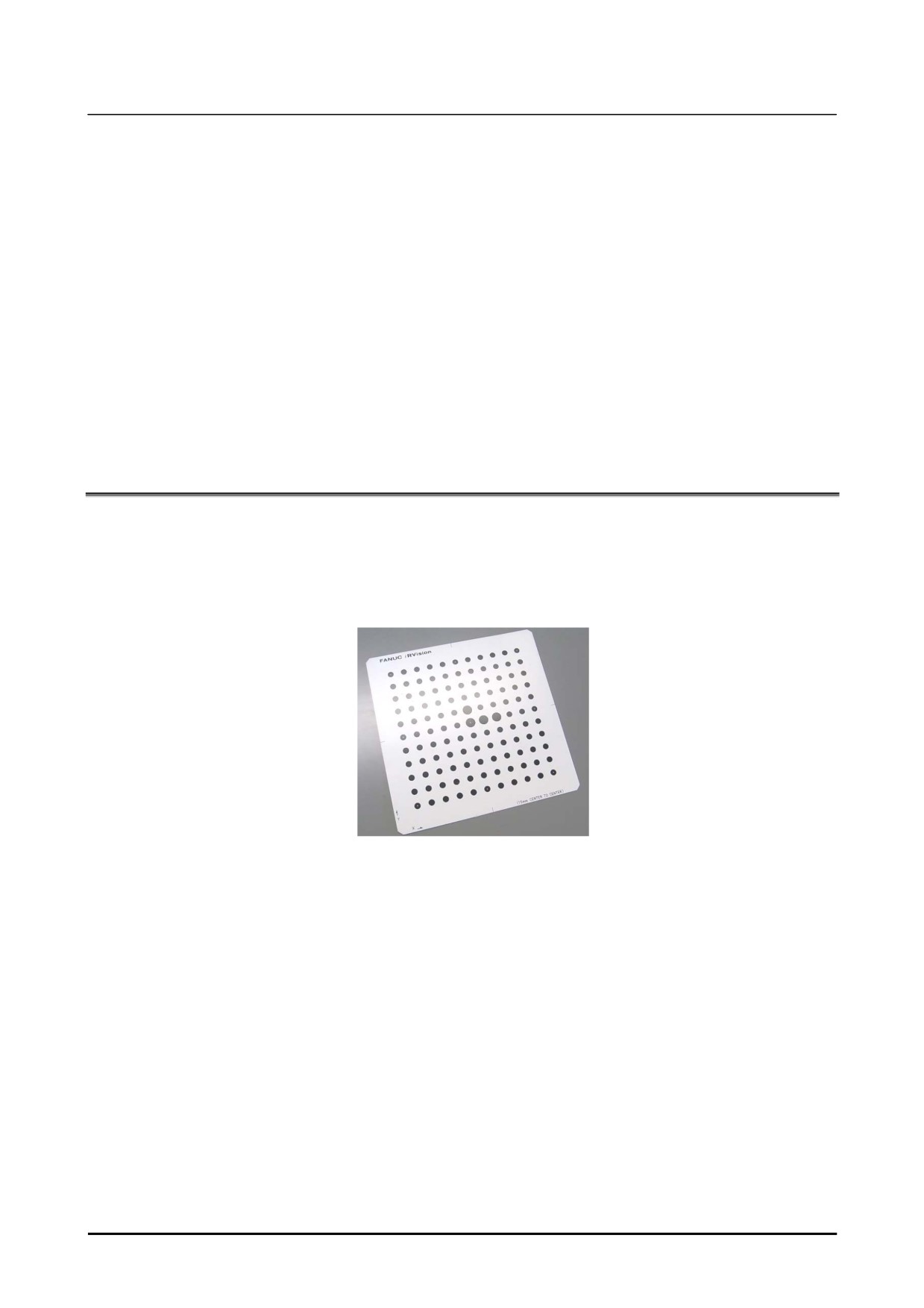
Grid pattern calibration is a general-purpose calibration method for cameras that uses a special jig called a
calibration grid. When using grid pattern calibration, prepare a calibration grid in advance. Usually,
prepare a calibration grid which is the bigger than a field of view. A standard calibration grid is
available from FANUC in several sizes. It is strongly recommended that you order a calibration grid as
well as a camera and lens.
It is not necessary to detect all the dots on the calibration grid. There are 11×11 dots in the standard
calibration grid of FANUC. If 7×7 dots are detected, the camera calibration is performed with sufficient
accuracy.
(The four big dots need to be detected.) In order to show all the dots in field of view, it is
not necessary to prepare a small calibration grid. In order to perform a calibration with accuracy
sufficient to the edge of the field of view, even if the number of detectable dots became fewer, prepare the
bigger calibration grid than a field of view.
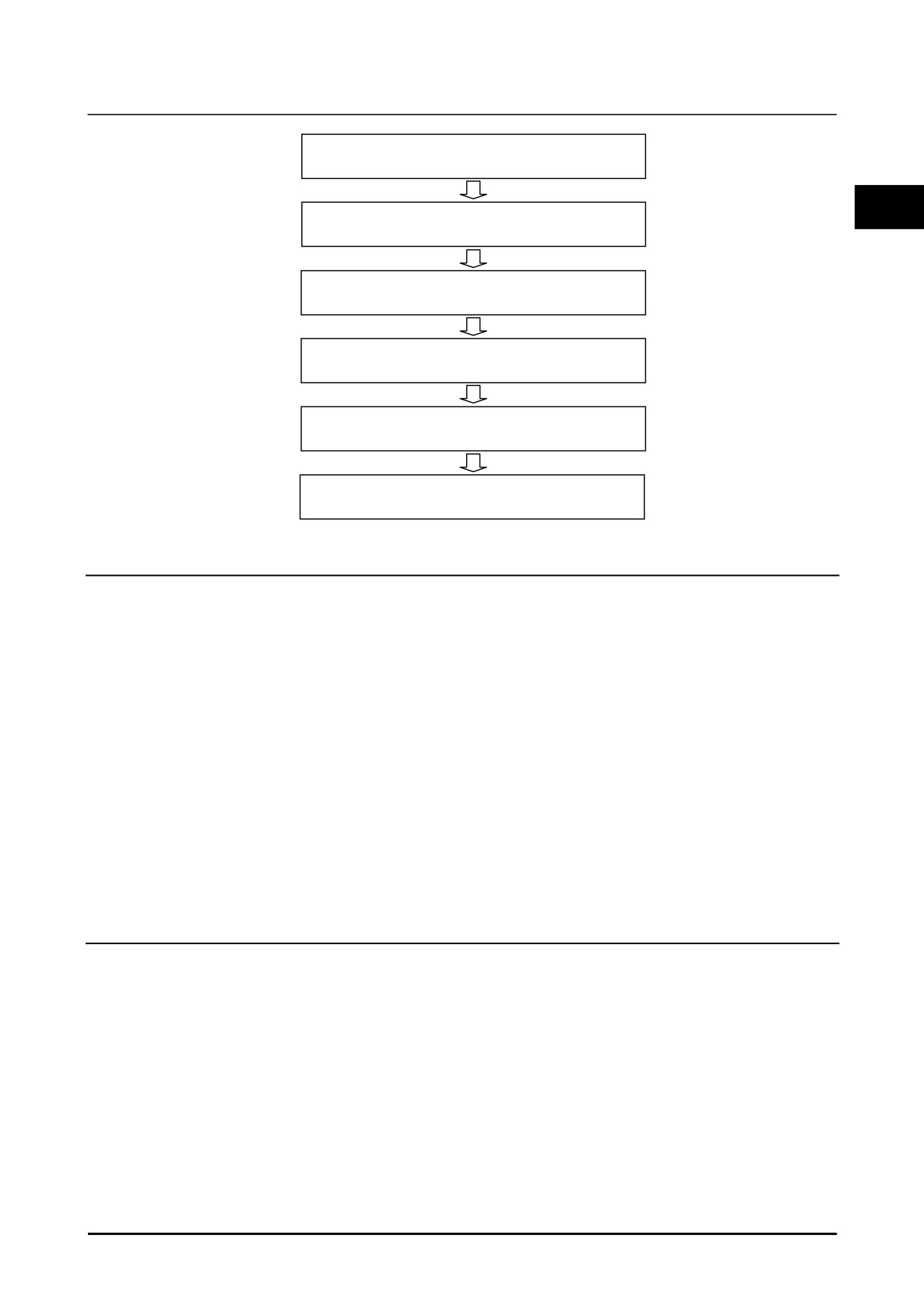
Use the following setup procedure for 'GRID PATTERN CALIBRATION WITH A ROBOT-MUONTED
CAMERA' :
172
B-83914EN-2/01
Know-How
2. CAMERA DATA SETTING
1 Application Frame Setting
2
2 Camera Data Creation
3 Camera Setup
4
Calibration
5
Checking Calibration Point
6
Checking Calibration Result
2.2.1
Application Frame Setting
Select a frame for the robot that will be the reference for calibration. Perform camera calibration using
the selected frame as the reference.
User frame [0: World frame] is selected as the default setting. In most cases, it does not need to be
changed. However, in the following cases, set up a user frame and perform calibration using that user
frame number as the application frame.
• In cases where the camera is attached to a robot other than the robot to be offset
• In cases where the calibration grid is attached to a robot other than the robot to be offset
• In cases where multiple robots are to be compensated using the same offset
Also, in cases like the above, it is necessary to carry out communication between robot controllers.
iRVision performs this communication when it is necessary, and for this, an interface function called
'ROS Interface Packet over Ethernet (RIPE)' is used internally. For robot systems to which the above
cases apply, refer to "12 ROS Interface Packet over Ethernet (RIPE)" in "R-30iA / R-30iA Mate / R-30iB
/ R-30iB Mate Controller Ethernet Function Manual B-82974EN" when setting up the RIPE functions.
2.2.2
Camera Data Creation
Create camera data for the 2D camera and set the camera type, method for camera installation, etc.
For details on the creation of vision tools, including camera data, refer to Setup Edition Subsection 1.3.1.1,
"Create" in the "R-30iB Plus CONTROLLER iRVision OPERATOR’S MANUAL
(Reference)
B-83914EN".
B-83914EN-2/01
173
2. CAMERA DATA SETTING
Know-How
2.2.3
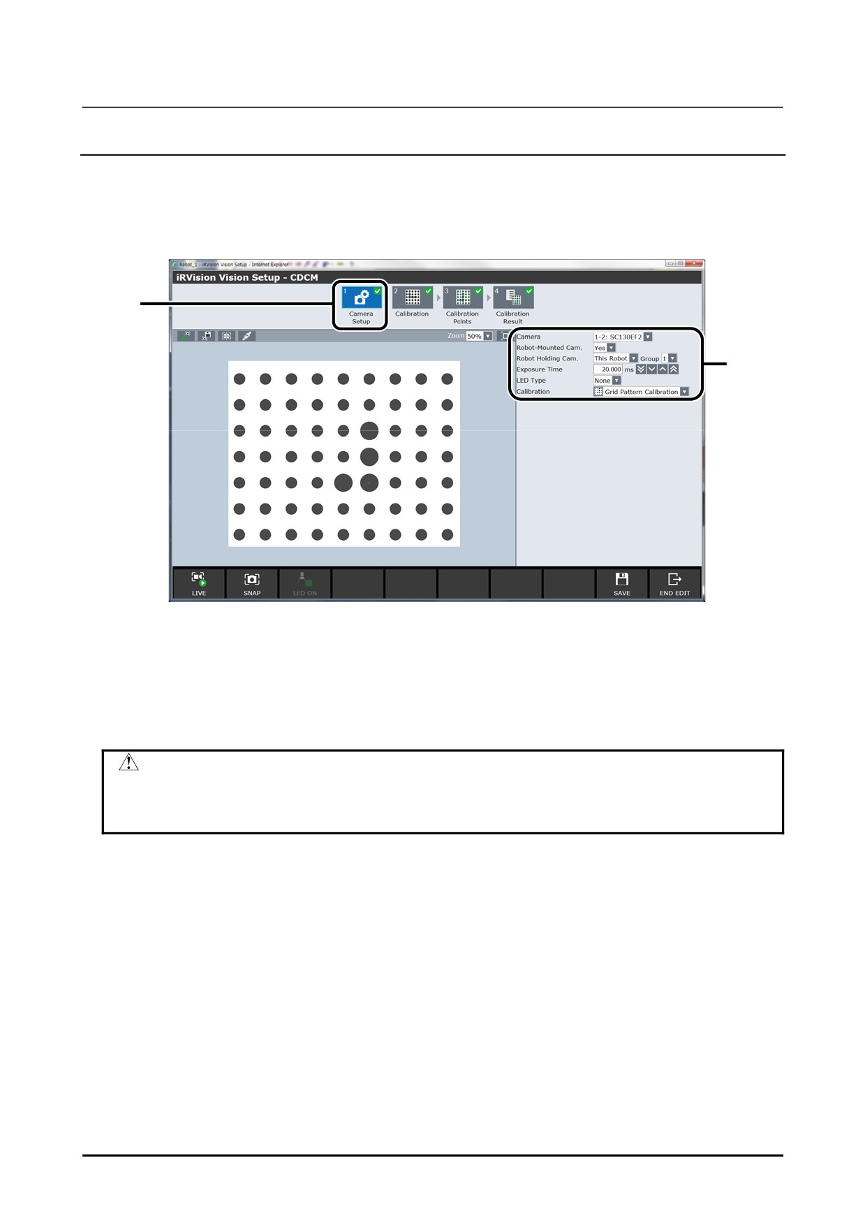
Camera Setup
Set the camera to use and the type of camera calibration for the camera data that has been created.
1
On the vision data list screen, click the camera data that has been created.
2
Click [Camera Setup] in the navigation area.
A screen like the following one will appear.
2
3, 4
3
Set the camera to use, the method for camera installation, the exposure time, the presence/absence of
LED lighting, etc.
If a camera has been attached to the robot's hand, select [Yes] for [Robot-Mounted Cam].
4
Select [Grid Pattern Calibration] for [Calibration].
5
Adjust the diaphragm and focus of the lens. If you click F1 [LIVE], a live image will be displayed
in the image view. Make adjustments while looking at the live image.
CAUTION
Adjust the diaphragm and focus of the lens before camera calibration. If the
diaphragm and focus are readjusted, camera calibration needs to be performed
again.
174
B-83914EN-2/01
Know-How
2. CAMERA DATA SETTING
2.2.4
Calibration
Detect the grid pattern and perform camera calibration.
2
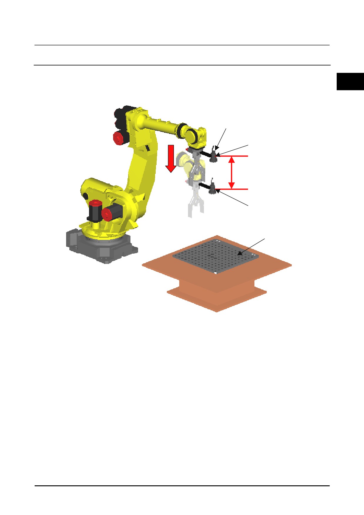
If a camera has been attached to the robot's gripper, perform calibration using two planes by moving the
robot vertically as shown in the figure below.
Camera
1st detection
100 to
150 mm
2nd detection
Calibration grid
Example of two-plane calibration when installing a camera on the robot's gripper
• In the 2D Single-view Vision Process, 2D Multi-view Vision Process or, in the 3D Tri-View Vision
Process, the up/down distance for two-plane calibration should be
100 to
150 mm. It is
recommended that the distance between the camera and the calibration grid for one of the planes is
the same as the distance between the camera and the workpiece.
• In the Depalletizing Vision Process, it is recommended that the up/down distance for two-plane
calibration be set to a value that covers the upper and lower ends of the workpiece in the pallet.
Find the calibration grid at two different heights. In this operation, ensure that the posture of the robot
for detecting the calibration grid is the same as the posture for detecting a workpiece. When moving the
camera up and down, jog the robot without changing the camera posture.
In cases where calibration is performed with the calibration grid fixed to a table, etc., set the installation
information for the calibration grid in a user frame with an arbitrary number. There are two methods for
setting a user frame: a method that uses a pointer tool, and a method that uses automatic grid frame set.
For details on setting using touch-up, refer to Know-how Edition Subsection 1.1.1, "User Frame Setting".
For details on setting using automatic grid frame set, refer to Know-how Edition Section 1.2, "FRAME
SETTING WITH THE GRID FRAME SETTING FUNCTION".
B-83914EN-2/01
175
2. CAMERA DATA SETTING
Know-How
Calibration Setting Procedure
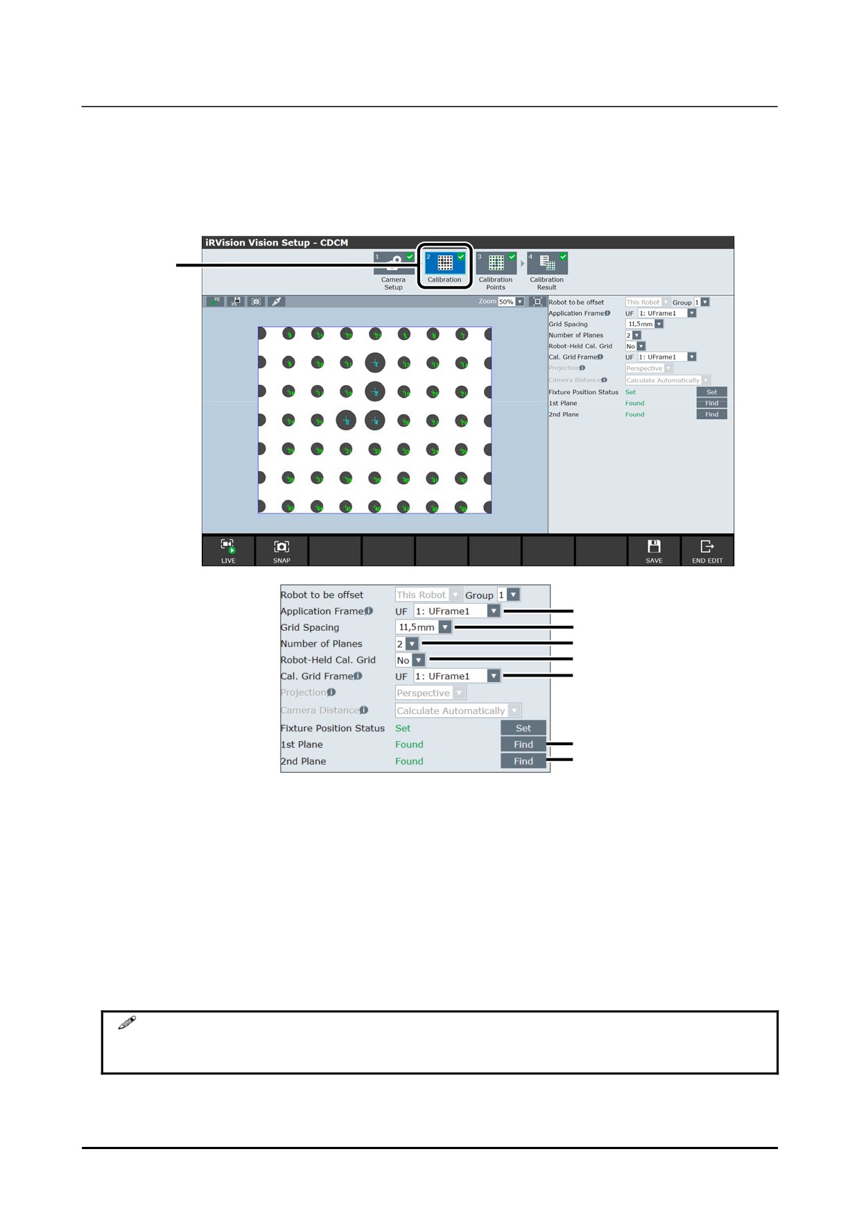
The calibration setting for when a camera is attached to the robot's gripper is as follows.
1
Select [Calibration] in the navigation area.
The grid pattern calibration setup screen will appear.
1
2
3
4
3
6
7
8
2
From the [Application Frame] drop-down box, select a frame for the robot that will be the reference
for calibration.
Specify the number of the user frame set in Know-how Edition Subsection 2.2.1, "Application
Frame Setting".
3
From the [Grid Spacing] drop-down box, select the grid spacing for the calibration grid.
4
From the [Number of Planes] drop-down box, select [2].
In cases where a camera is installed on the robot's gripper, calibration will be performed using two
planes.
5
From the [Robot-Held Cal. Grid] drop-down box, select [No].
6
From the [Cal. Grid Frame] drop-down box, select the number of the user frame in which the
calibration grid installation information was recorded.
MEMO
Note that the frame for [Cal. Grid Frame] is different from the [Application Frame]
or the [Offset Frame] setting.
7
Detect the 1st Plane. Move the camera until it is an appropriate distance from the calibration grid,
and after clicking [SNAP], click the [FIND] button.
176
B-83914EN-2/01
Know-How
2. CAMERA DATA SETTING
8
Detect the 2nd Plane. Change the distance between the camera and the calibration grid, and after
clicking [SNAP], click the [FIND] button for [2nd Plane].
For details on the settings after finding an image, refer to Know-how Edition Subsection 2.2.5,
"Checking Calibration Point" and Know-how Edition Subsection 2.2.6, "Checking Calibration
2
Result".
2.2.5
Checking Calibration Point
Check the calibration point found in Know-how Edition Subsection 2.2.4, "Calibration".
Click [Calibration Points] in the navigation area. A calibration point screen like the following will
appear.
1
1
2
If there are points found other than the dot positions of the calibration grid, delete the irrelevant found
points using the following procedure.
1
Select an irrelevant found point from the found point list, or enter a found point number in the [Point
Number] text box.
2
Click the [DELETE] button to delete the irrelevant found point.
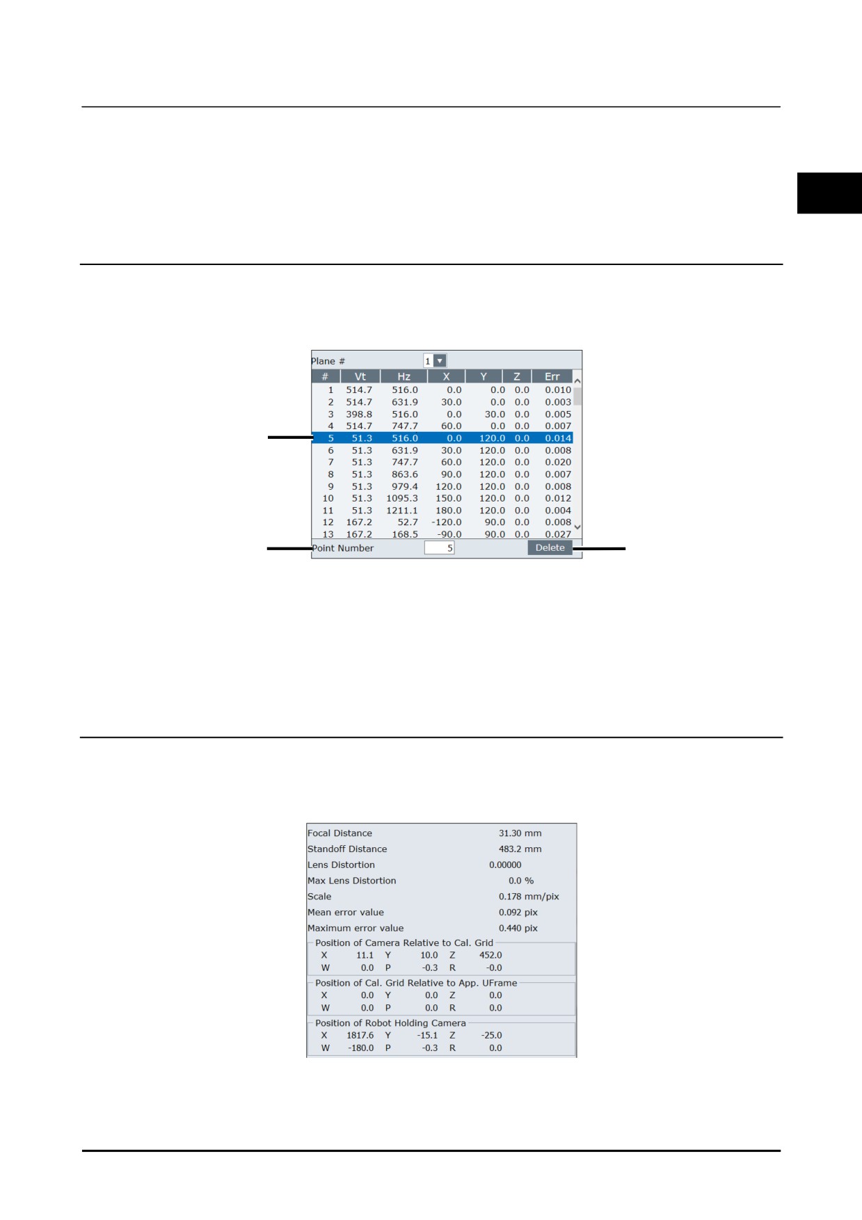
2.2.6
Checking Calibration Result
Check the calculated calibration data.
If you click [Calibration Result] in the navigation area, a calibration result screen like the following will
appear.
[Scale] indicates how many mm one pixel on an image is equivalent to. It can be calculated by dividing
the size of field of view by the image size.
B-83914EN-2/01
177
2. CAMERA DATA SETTING
Know-How
Example:
If the size of field of view is 262×169 mm and the image size is 640×480 pix, the scale will be as
follows.
0.409 mm/pix = 262 mm ÷ 640 pix
If there is a large error in the [Scale], check whether the installation information for the calibration grid
has been correctly set, and the [Grid Spacing] has been correctly input.
[Scale] changes depending on
the distance from the camera, so it will not be constant within the field of view. The displayed value for
[Scale] is an average value for near the calibration plane.
If there is no problem with the calibration points and calibration result, then the calibration is complete.
Click [SAVE] to save the data, then click [END EDIT].
The calibration grid can now be removed.
178
B-83914EN-2/01
Know-How
2. CAMERA DATA SETTING
2.3
ROBOT-GENERATED GRID CALIBRATION
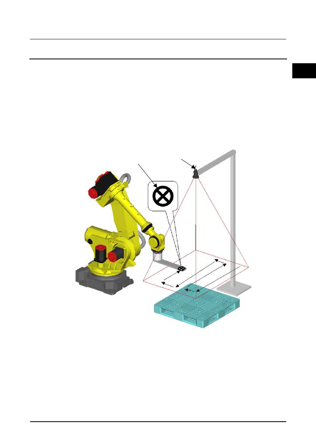
Robot-Generated Grid Calibration is a type of general-purpose camera calibration function similar to Grid
2
Pattern Calibration. The function moves the target, mounted on the robot end of arm tooling, in the
camera's field of view to generate a virtual grid pattern for camera calibration. Unlike Grid Pattern
Calibration, this calibration method does not require a calibration grid as large as the camera’s field of
view and is therefore suitable for calibrating a wide-view-angle camera. Also, since it performs 2-plane
calibration, the calibration method enables you to accurately calculate the position of the camera and the
focal distance of the lens in use. The robot automatically moves and measures the position of the target
and the size of the camera's field of view. When performing the calibration of the fixed camera, the
Robot-generated Grid Calibration can be used.
When using a robot-mounted camera, the
Robot-generated Grid Calibration cannot be used. When using a robot-mounted camera, perform the
Grid Pattern Calibration for a camera calibration.
Fixed camera
Target
Example of a layout for robot-generated grid calibration
B-83914EN-2/01
179
2. CAMERA DATA SETTING
Know-How
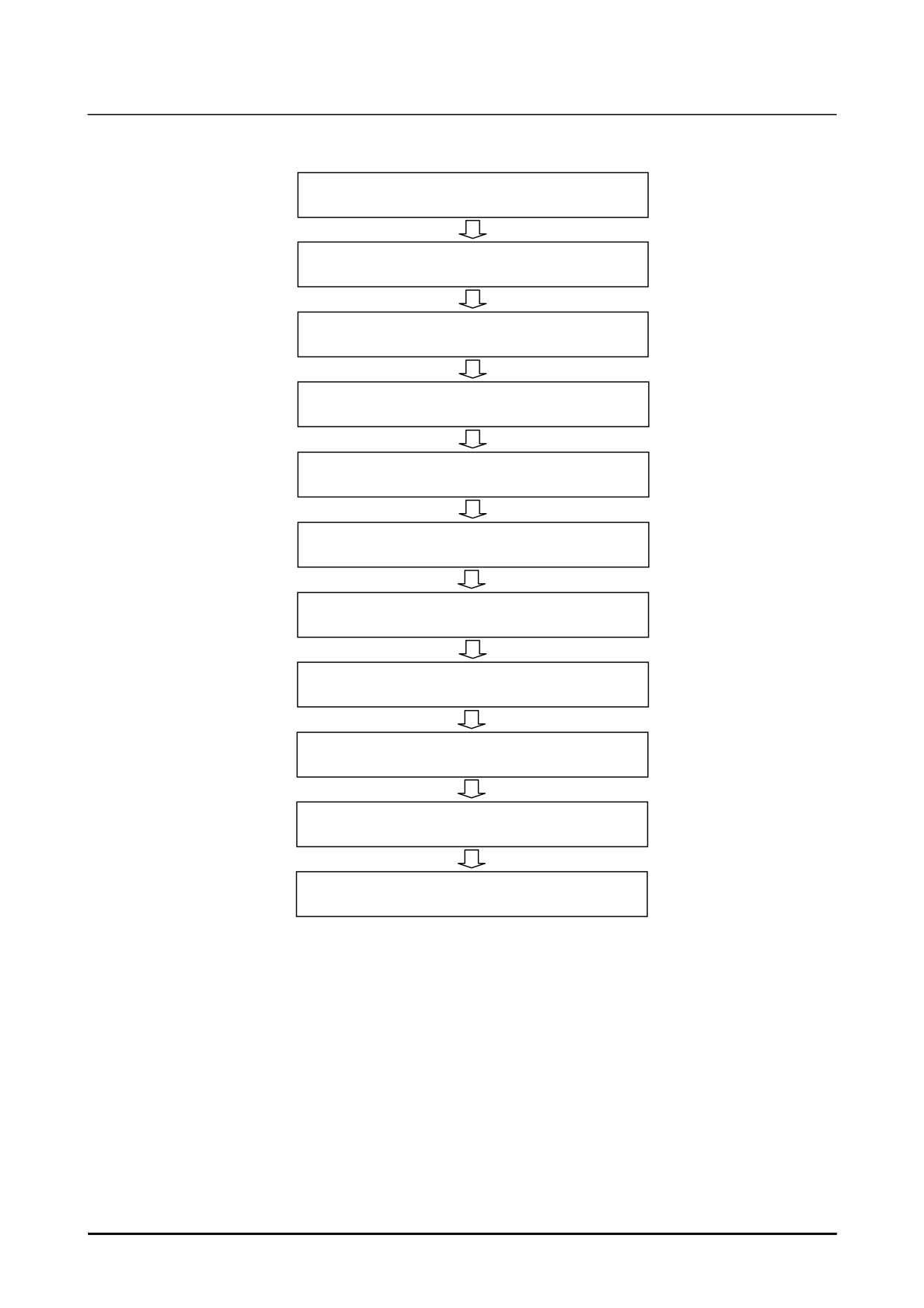
Set up robot-generated grid calibration using the following procedure.
1
Application Frame Setting
2
Selecting and Mounting the Target
3
Camera Data Creation
4
Camera Setup
5
Calibration Setup
6 Camera Data Selection
7
Measuring Target Position(Vision Utility Screen)
8
Generating Calibration Program(Vision Utility Screen)
9
Executing Calibration Program(Vision Utility Screen)
10 Checking Calibration Point
11 Checking Calibration Result
Positioning pins or other appropriate means may be used so that the target can be mounted at the same
position for each measurement. This way, a robot program generated for a previous calibration
operation can be used for re-calibration. In such cases, re-calibration of a camera can be performed
simply by carrying out step 9.
180
B-83914EN-2/01
Know-How
2. CAMERA DATA SETTING
2.3.1
Application Frame Setting
Select a frame for the robot that will be the reference for calibration. Perform camera calibration using
the selected frame as the reference.
2
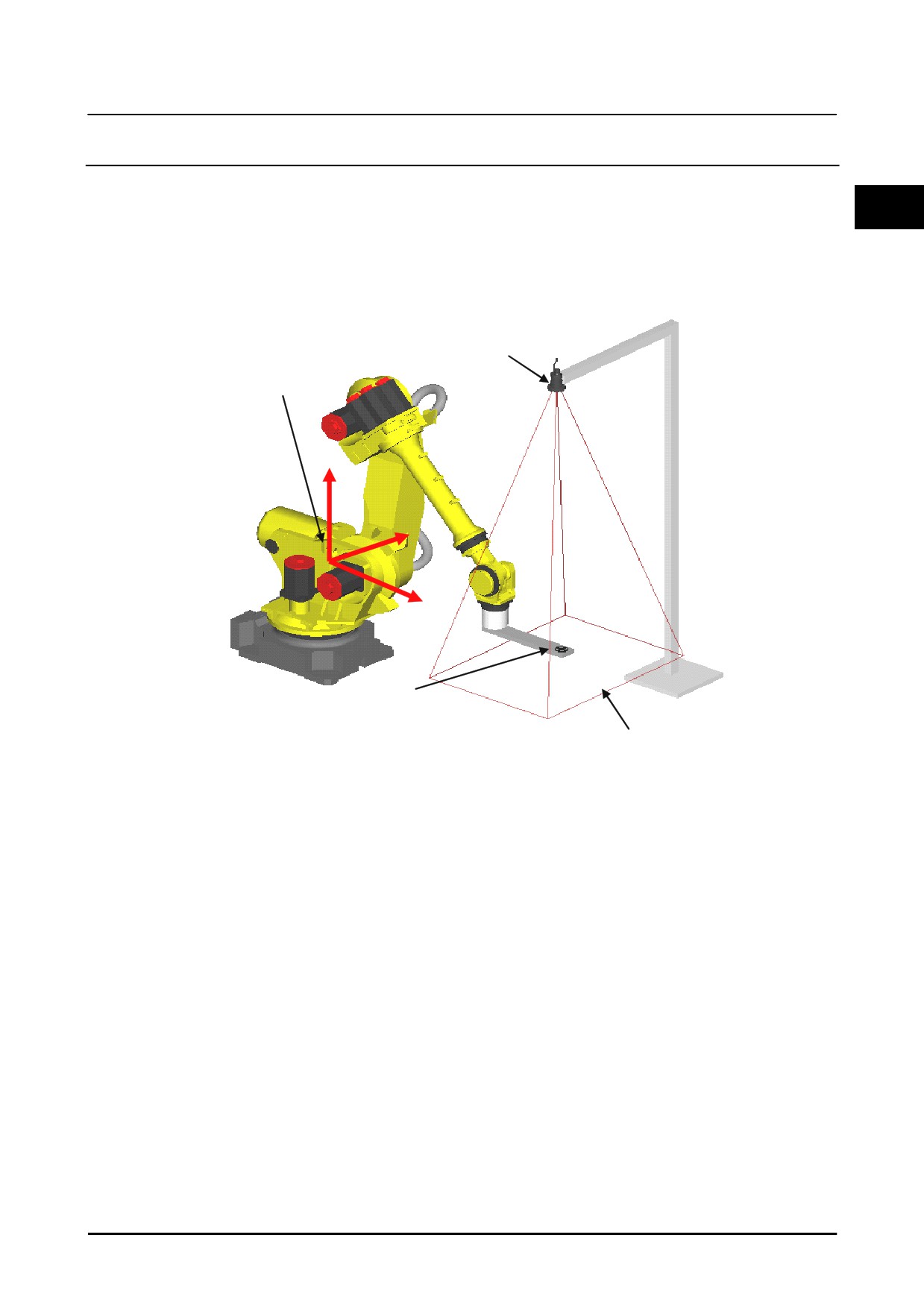
Set an application frame so that the XY plane of the application frame is almost parallel with the
calibration plane. During camera calibration, the robot moves in parallel to the XY plane of the
application frame. As shown in the figure below, if the calibration plane and the XY plane of the world
frame are almost parallel, a user frame [0: World frame] can also be selected as the application frame.
Camera
Application frame
(Base frame)
Z
Y
X
Target
Calibration plane.
Calibration plane and world frame
B-83914EN-2/01
181
2. CAMERA DATA SETTING
Know-How
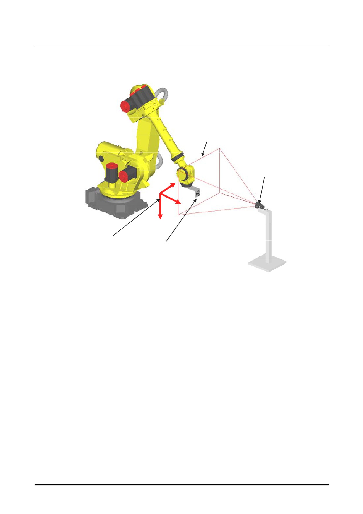
As shown below, set a user frame so that the XY plane of the user frame is parallel with the calibration
plane. A user frame number is arbitrary, and use this user frame number as the application frame
number.
Plane on which robot moves (calibration plane)
Camera
Y
Z
X
Application frame(user frame)
Target
Calibration plane and user frame
182
B-83914EN-2/01
Know-How
2. CAMERA DATA SETTING
2.3.2
Selecting and Mounting the Target
Select the target mark to be used for calibration.
2
Geometry of the target
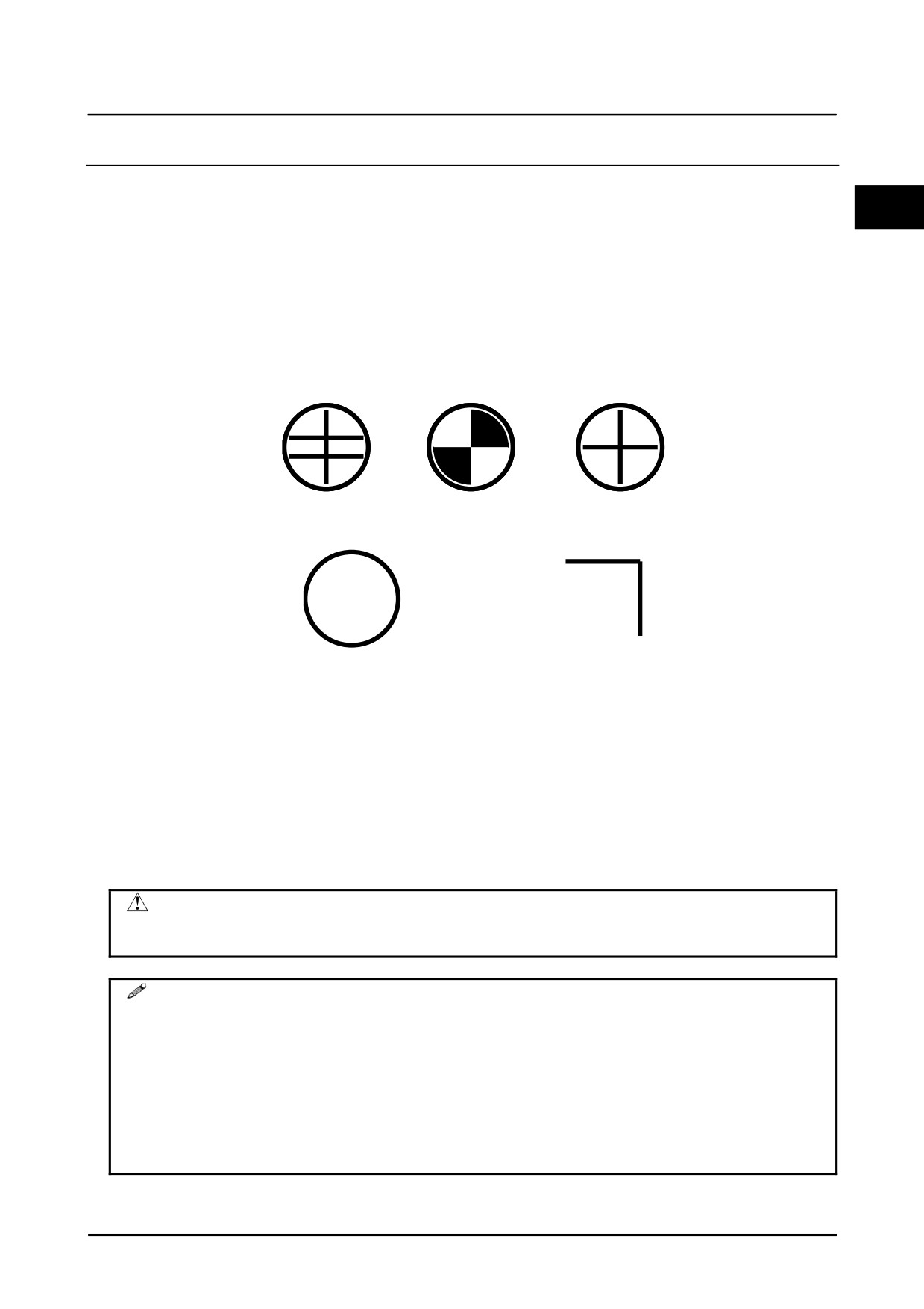
The target must meet the following conditions:
The features to be taught are on the same one plane.
The target has a geometry for which any rotation of 45 or so can be identified.
The target has a geometry whose size can be identified.
Below are examples of appropriate/inappropriate shapes for the target.
Examples of appropriate shapes for the target
The rotation angle cannot be identified.
The size cannot be identified.
Examples of inappropriate appropriate shapes for the target
Size of the target
The target should be something whose size will be approximately 80 to 100 pixels long and wide when it
is snapped as an image.
Mounting the target
Mount the target at the robot end of arm tooling. Make sure that the target does not get behind the robot
arm or the tooling even when the robot moves in the camera's field of view.
CAUTION
Fix the target securely to the robot's gripper so that it will not get off position while
robot is operating.
MEMO
1 Normally, the robot position and posture are set so that the range of robot motion
becomes maximal when the robot actually operates. Therefore, mounting the
target so that it can be captured by the camera when the robot is in a posture that
it takes during operation makes it easier to secure the range of robot motion.
2 Positioning pins or other appropriate means may be used so that the target can
be mounted at the same position for each measurement. This way, a robot
program generated for a previous calibration operation can be used for
re-calibration.
B-83914EN-2/01
183
2. CAMERA DATA SETTING
Know-How
2.3.3
Camera Data Creation
Create camera data for the 2D camera and set the camera type, method for camera installation, etc.
For details on the creation of vision tools including camera data, refer to Setup Edition Subsection 1.3.1.1,
"Create" in "R-30iB Plus CONTROLLER iRVision OPERATOR’S MANUAL (Reference) B-83914EN".
2.3.4
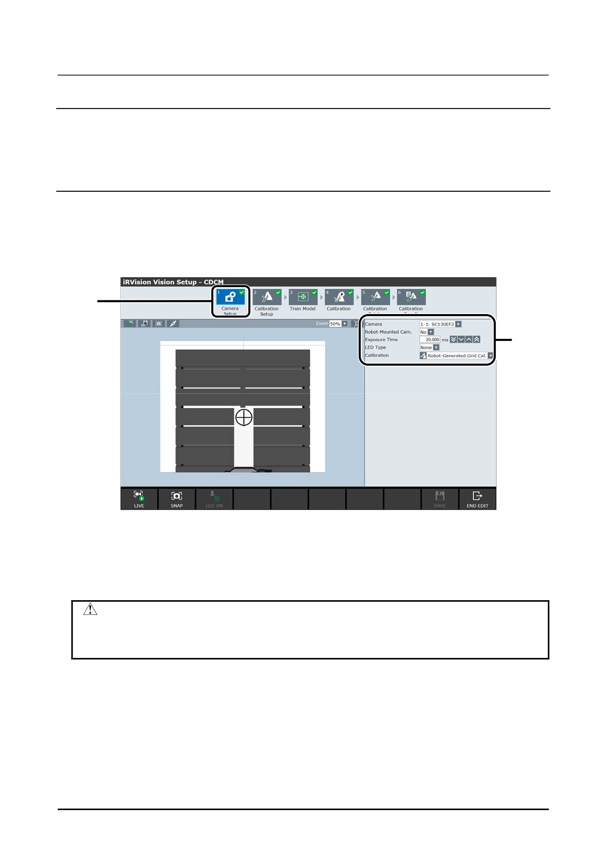
Camera Setup
Set the camera to use and the type of camera calibration for the camera data that has been created.
1
On the vision data list screen, click the camera data that has been created.
2
Click [Camera Setup] in the navigation area.
A screen like the following one will appear.
2
3, 4
3
Set the camera to use, the method for camera installation, the exposure time, the presence/absence of
LED lighting, etc.
4
Select [Robot-Generated Grid Cal.] for [Calibration].
5
Adjust the diaphragm and focus of the lens. If you click [LIVE], a live image will be displayed in
the image view. Make adjustments while looking at the live image.
CAUTION
Adjust the diaphragm and focus of the lens before performing camera calibration.
If the diaphragm and focus are readjusted, camera calibration needs to be
performed again.
184
B-83914EN-2/01
Know-How
2. CAMERA DATA SETTING
2.3.5
Calibration Setup
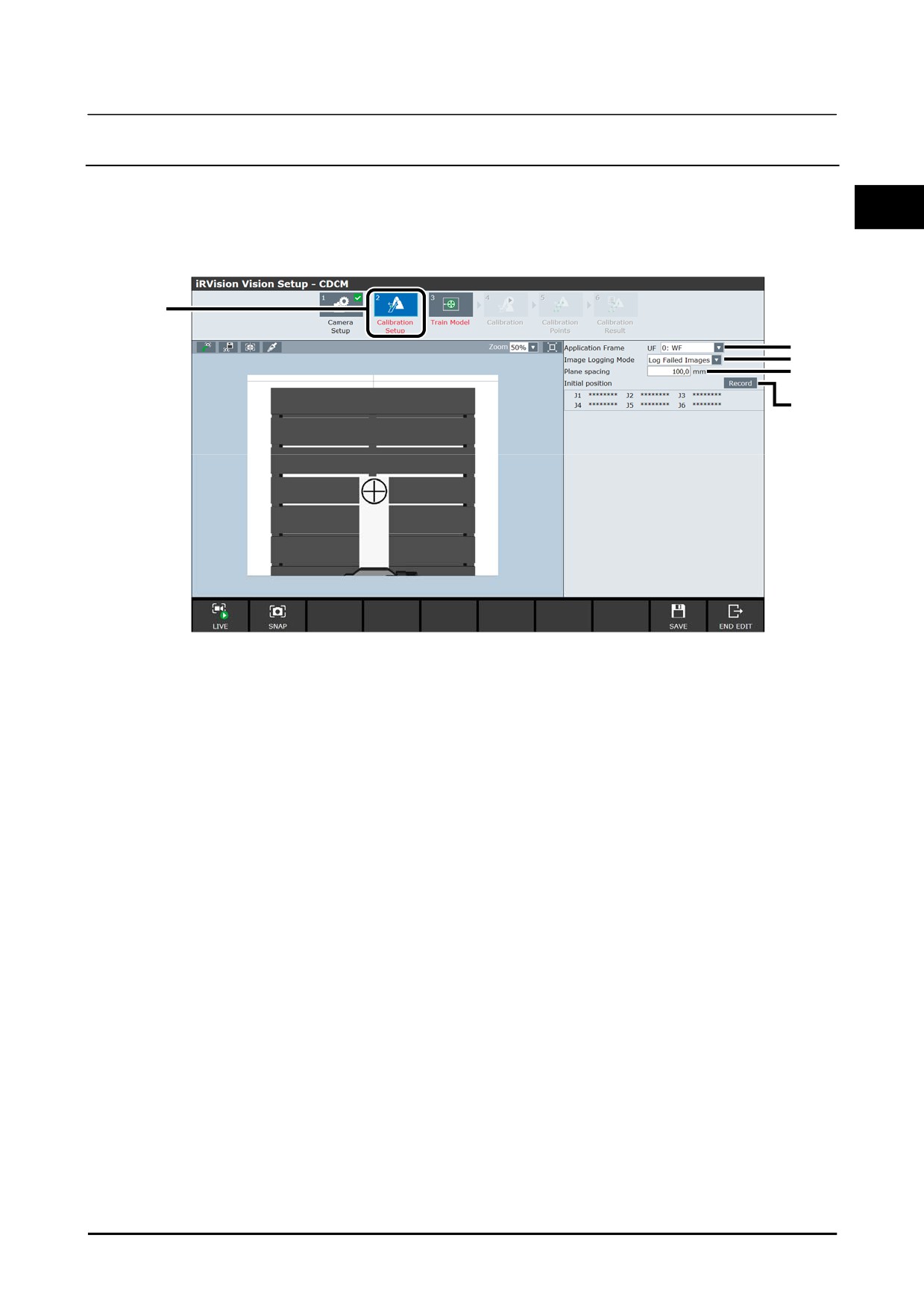
Perform the necessary setup for robot-generated grid calibration on the calibration setup screen.
2
1
Select [Calibration Setup] in the navigation area.
The robot-generated grid calibration setup screen will appear.
1
2
3
4
9
2
From the [Application Frame] drop-down box, select a frame for the robot that will be the reference
for calibration.
Specify the number of the user frame set in Know-how Edition Subsection 2.3.1, [Application
Frame Setting].
3
From the [Image Logging Mode] drop-down box, select whether you are going to record logged
images while executing calibration.
4
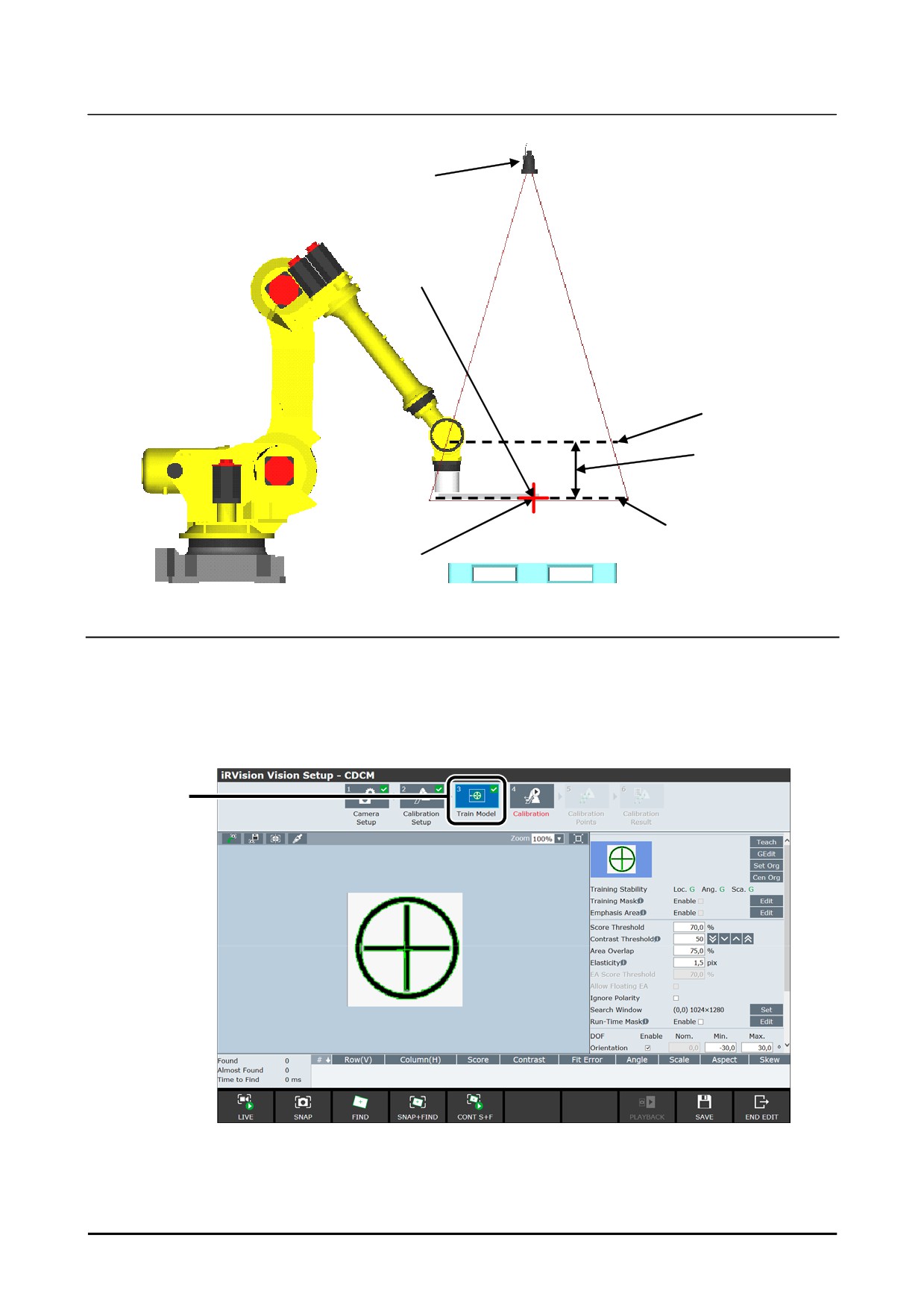
Enter the spacing between the 1st Plane and the 2nd Plane in the [Plane spacing] text box.
For the plane spacing, approximately 10% of the spacing between the camera and the 1st Plane is
suitable. If the application frame's Z-axis is facing the camera, by setting a positive value, the 2nd
Plane will be set to be closer to the camera than the 1st Plane, which will reduce the risk of
interference with the surrounding devices during operation. If the application frame's Z-axis is
facing in the opposite direction to the camera, by setting a negative value, the 2nd Plane will be set
to be closer to the camera than the 1st Plane.
5
Click the [RECORD] button for [Initial position]. Record the initial position.
The initial position should be set so that the target attached to the robot's gripper appears roughly in
the center of the camera's field of view. The height of the initial position will be the height of the
1st Plane. During camera calibration, the robot will move in parallel to the XY plane of the
application frame while keeping the posture of the initial position. Move the robot by jog operation
to a position that will be appropriate as the initial position, and click the [RECORD] button at that
position to record the initial position.
B-83914EN-2/01
185
2. CAMERA DATA SETTING
Know-How
Camera
Measurement start position
First calibration plane
Plane spacing
Second calibration plane
Target
2.3.6
Teaching Model
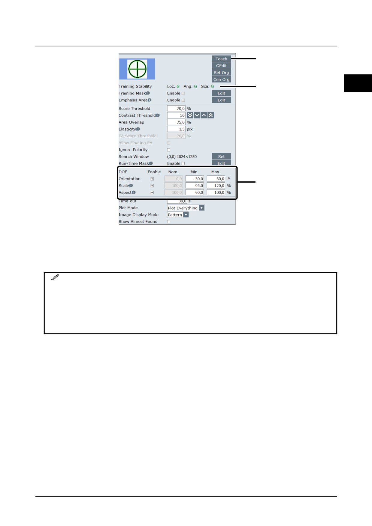
Teach the shape of the target to use for calibration as a model pattern for the pattern match tool. Model
pattern teaching is performed after moving the robot to the recorded initial position.
1
Click [Train Model] in the navigation area.
A screen like the following one will appear.
1
186
B-83914EN-2/01
Know-How
2. CAMERA DATA SETTING
2
3
2
4
2
Click the [Teach] button.
A full-screen image will be displayed, and a rectangular window (reddish purple rectangle) will
appear. Surround the target to teach with the rectangular window, and click [OK]. The model
pattern will be taught.
MEMO
Make the size of the rectangular window slightly larger than the target. During
measurement, the zone of the rectangular window taught here will control the
position of the robot so that it does not go out of the search window. Therefore,
if the taught zone is too large compared to the target, it will not be possible to
move the target to the edge of the field of view, and this may result in an
inaccurate calibration result.
3
If a model pattern is taught, the evaluation result for the model that is taught will be displayed for
[Training Stability] will be displayed.
Check that there is a ○ for Location, Angle, and Scale. Even a single will mean calibration
cannot be performed successfully, so change the shape of the target in such cases.
4
The default settings for [DOF] are ±30 for [Orientation], 95 to 120% for [Scale], and 90 to 100%
for [Aspect]. Normally, these do not need to be changed, but adjust them as required.
B-83914EN-2/01
187
2. CAMERA DATA SETTING
Know-How
2.3.7
Camera Data Selection
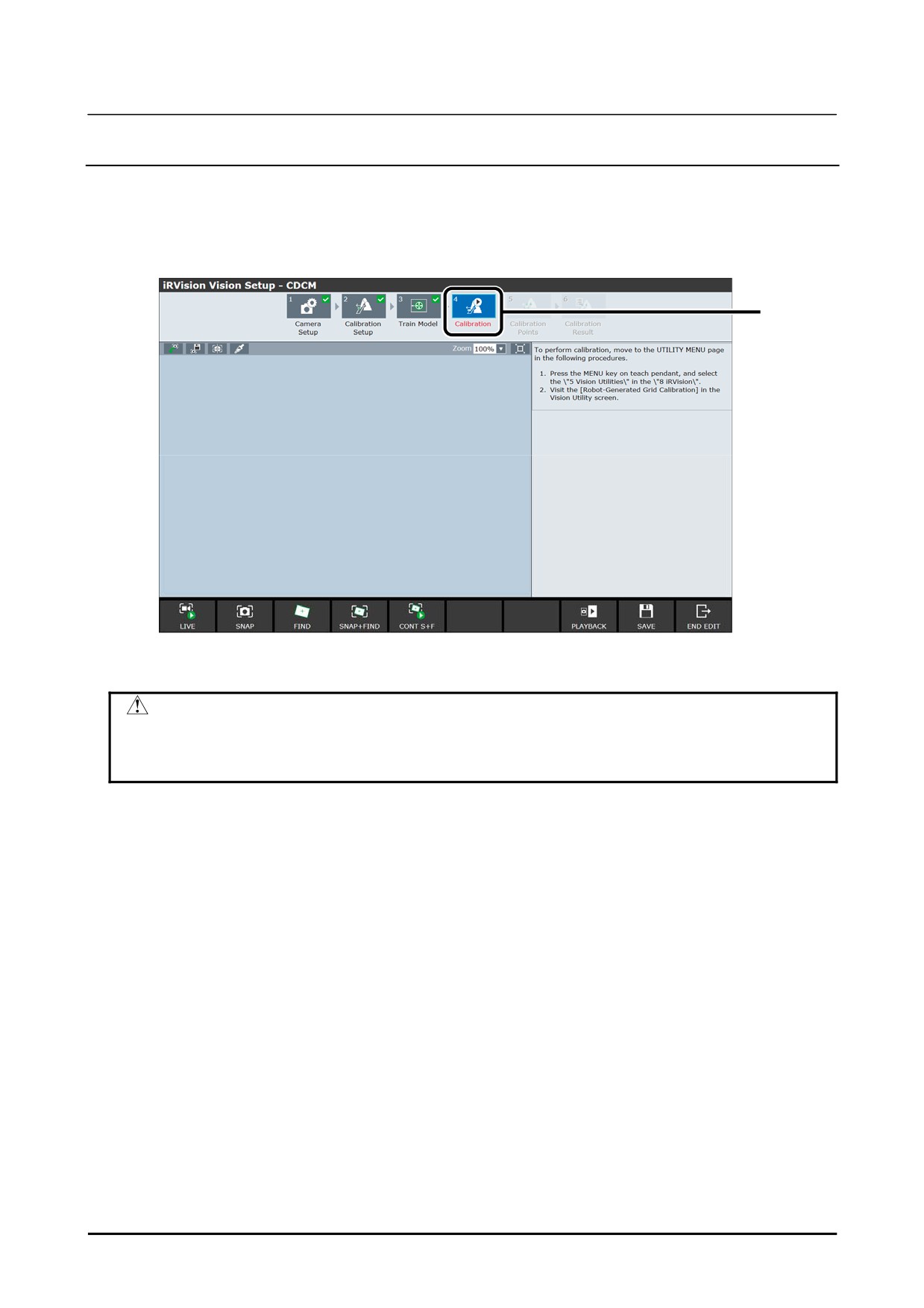
In order to execute camera calibration, select camera data on the iRVision utility screen.
1
Click [Calibration] in the navigation area.
A screen like the following one will appear.
1
2
Click [SAVE] on the camera data edit screen, and click [END EDIT].
CAUTION
In order to execute robot-generated grid calibration, it is necessary to close the
camera data edit screen of the teaching PC and perform setup after displaying
the iRVision utility screen on the teach pendant.
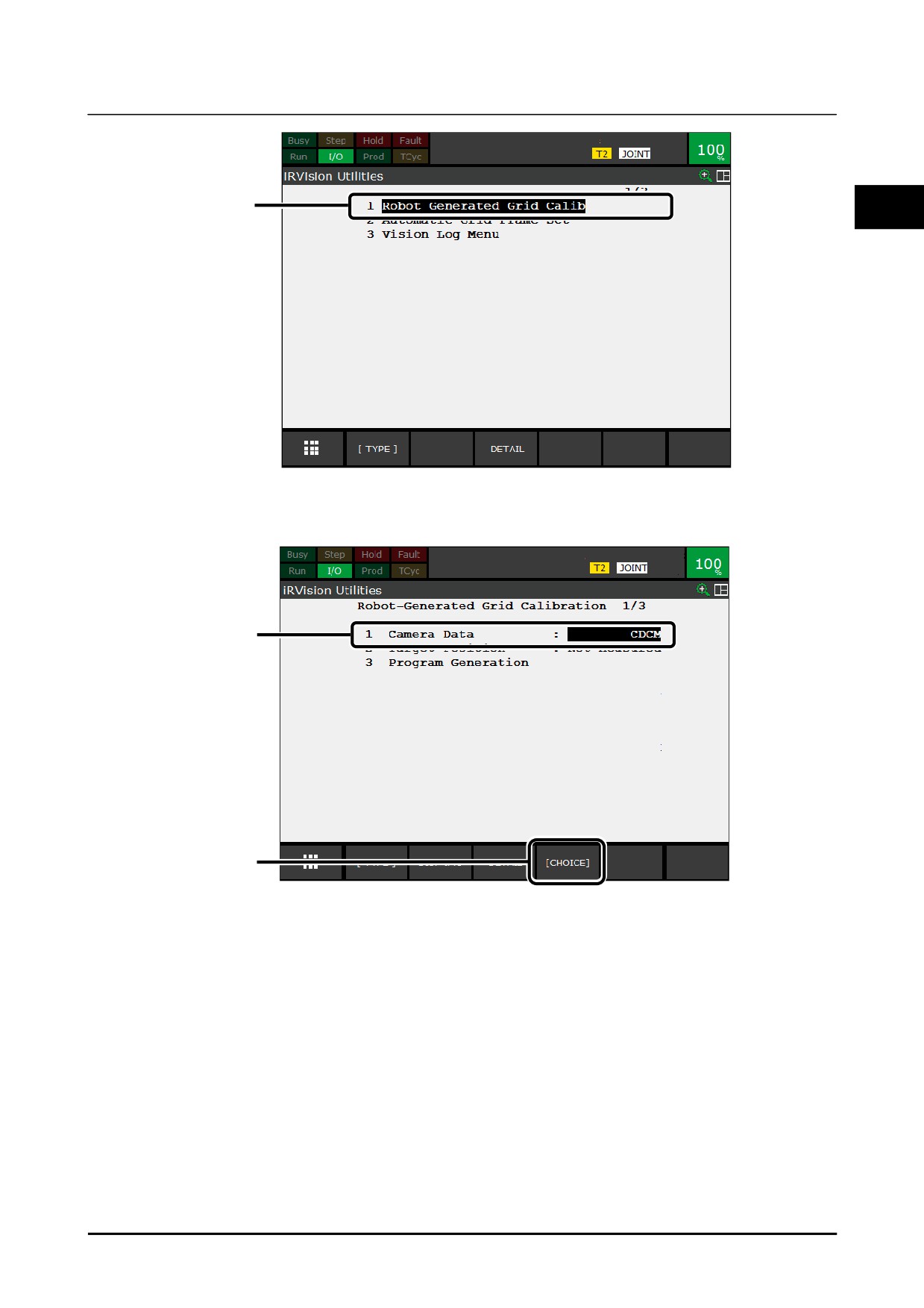
3
On the teach pendant, after selecting the
[MENU] key → [iRVision], place the cursor over
[Utilities] and press the [ENTER] key.
The iRVision utility screen will appear.
188
B-83914EN-2/01
Know-How
2. CAMERA DATA SETTING
4
2
4
Place the cursor over [Robot Generated Grid Calib] and press the [ENTER] key.
The main screen for robot-generated grid calibration will appear.
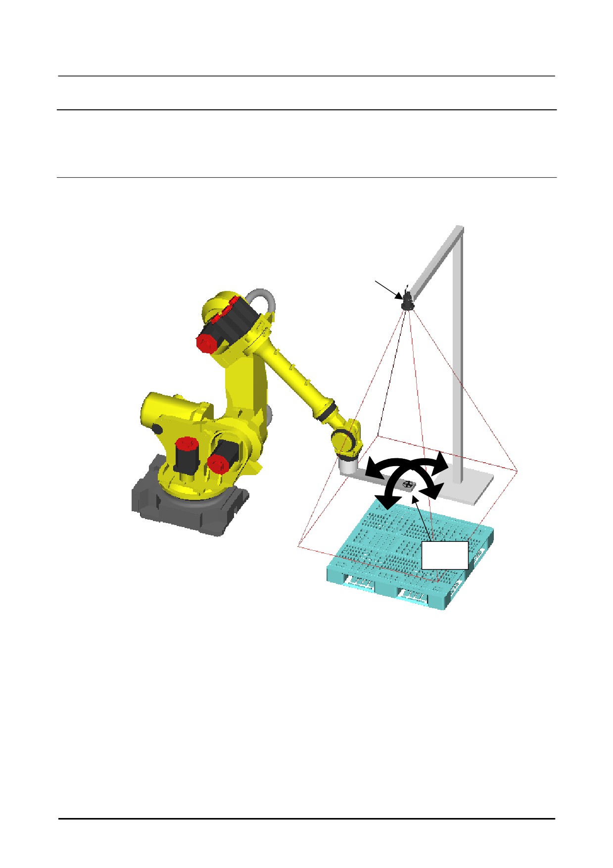
5
6
5
Place the cursor over [Camera Data].
6
Press F4 [CHOICE].
A list of camera data will appear.
7
Place the cursor over the name of the camera data taught in Know-how Edition Subsection 2.3.5,
"Calibration Setup" and press the [ENTER] key.
The selected camera data name will be displayed for [Camera Data].
B-83914EN-2/01
189
2. CAMERA DATA SETTING
Know-How
2.3.8
Measuring Target Position
For a 6-axis robot, the target position can be set automatically by measuring the target with a camera
attached to the robot's gripper. For a 4- or 5-axis robot, the target position cannot be set automatically.
2.3.8.1
6-axis robot
The robot performs measurement by changing the target position and posture as shown in the figure
below.
Camera
Target
Target position measurement (for 6-axis robot)
190
B-83914EN-2/01
Know-How
2. CAMERA DATA SETTING
Measure the target position using the following procedure.
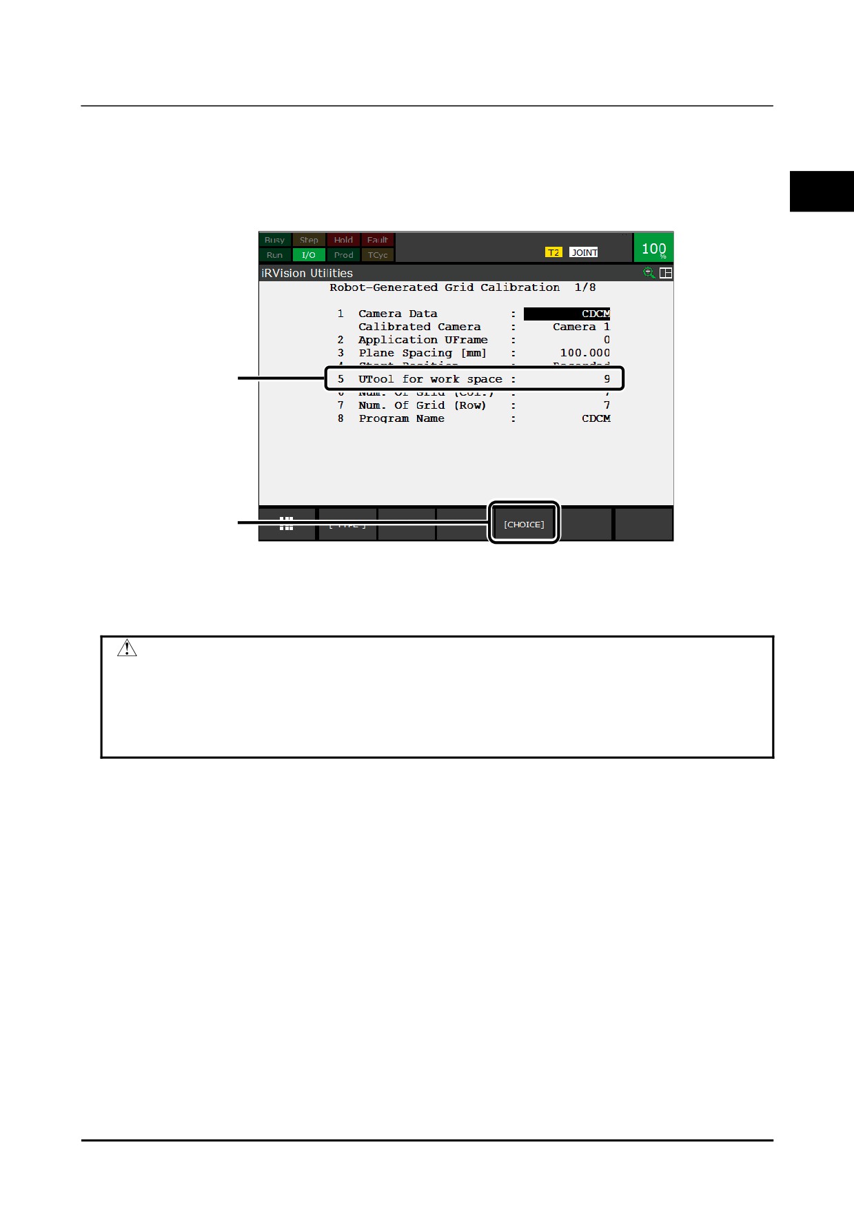
1
Place the cursor over [Camera Data], and after checking the camera data name, press F3 [DETAIL]
after checking the camera data name.
2
A detailed screen of camera data will appear.
2
3
2
Place the cursor over [UTool for work space].
3
Press F4 [CHOICE].
4
Specify the number of a tool frame for which there will be problems even if its values are changed.
CAUTION
Robot-generated grid calibration uses one tool frame as a working frame for
target position measurement and the creation of a program for the calibration.
As measurement is performed by rewriting the values for the specified tool frame,
specify the number of a tool frame for which there will be problems even if its
values are changed.
5
Press the [PREV] key.
The screen returns to the robot-generated grid calibration main screen.
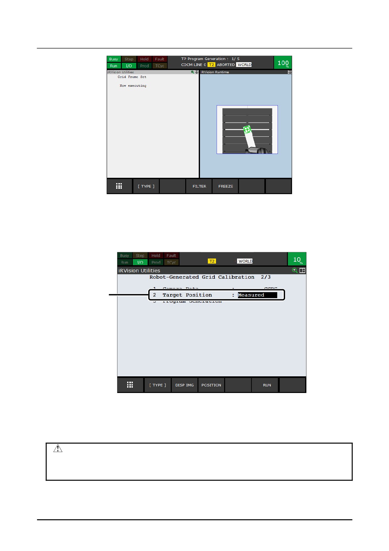
6
Place the cursor over [Target Position].
7
Press F2 [DISP IMG] and display Vision Runtime.
8
Enable the teach pendant and clear the alarm.
9
Place the cursor over [Target Position], and while holding down the [SHIFT] key, press F5 [RUN].
The robot will start target position measurement.
Keep the [SHIFT] key held down during measurement.
B-83914EN-2/01
191
2. CAMERA DATA SETTING
Know-How
10 When the measurement finishes, the robot will stop, and a message saying [Measurement is
successfully] will be displayed on the screen.
11 Release the [SHIFT] key and press F4 [OK].
The screen returns to the robot-generated grid calibration main screen. Check that the status of
[Target Position] is [Measured].
11
If the previous target measurement was interrupted midway, a message saying 'Are you sure to resume?'
will be displayed if you try to execute target measurement. To resume from where it was interrupted,
press F4 [RESUME] while holding down the [SHIFT] key. If you want to start it over from the
beginning, press F5 [RESTART] while holding down the [SHIFT] key.
CAUTION
Measurement cannot be executed if the camera data edit screen of the teaching
PC is being displayed. Close the camera data edit screen. How measurement
is going can be checked using Vision Runtime.
192
B-83914EN-2/01