FANUC Series 0i-MODEL D, Series 0i Mate-MODEL D. For Machining Center System USER’S MANUAL - page 9
6.COMPENSATION FUNCTION
PROGRAMMING
B-64304EN-2/01
Limitation
- Commands related to reference position return and the coordinate system
In coordinate system rotation mode, G codes related to reference
position return (G27, G28, G29, G30, etc.) and those for changing the
coordinate system (G52 to G59, G92, etc.) must not be specified. If
any of these G codes is necessary, specify it only after canceling
coordinate system rotation mode. If it is specified without canceling
scaling, the alarm PS0412 is issued.
- Incremental programming
The first move command after the coordinate system rotation cancel
command (G69) must be specified with absolute values. If an
incremental move command is specified, correct movement will not
be performed.
- Note on the specification of one axis in coordinate system rotation
With the parameter below, a move position in the case where one axis
is specified in the absolute mode can selected. If two axes are
specified, a movement is made to the same position, regardless of the
setting of the parameter.
Parameter AX1 (No. 11600#5)
If one axis is specified in the absolute mode when the coordinate
system rotation mode is set:
0: The specified position is first calculated in the coordinate system
before rotation then the coordinate system is rotated.
1: The coordinate system is first rotated then a movement is made to
the specified position in the rotated coordinate system.
(FS0i-compatible specification)
This parameter changes the handling of coordinates on axes not
specified, so that a position to be reached by movement changes.
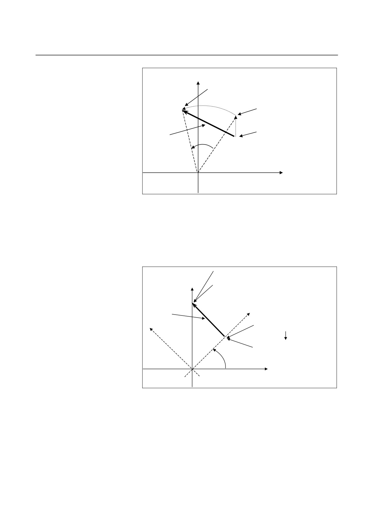
(Example)
G90 G0 X0 Y0
G01 X10. Y10. F6000
G68 X0 Y0 R45
Specifies coordinate system rotation.
Y14.142
Specifies one axis
(1)
G69
When parameter AX1 (No. 11600#5) = 0:
The specified position is calculated in the coordinate system
(XY) before rotation then the coordinate system is rotated.
So, with the specification of
(1), the position on the
unspecified X axis is X10, and the specified position is
(X10,Y14.142). Next, a movement is made to the move
position (X-2.929,Y17.071) obtained by 45° rotation.
- 226 -
B-64304EN-2/01
PROGRAMMING
6.COMPENSATION FUNCTION
Y
Move position
: X-2.929,Y17.071
Specified position
: X10,Y14.142
Coordinates before
Tool path
●
45°
coordinate system rotation is
specified
: X10,Y10
X
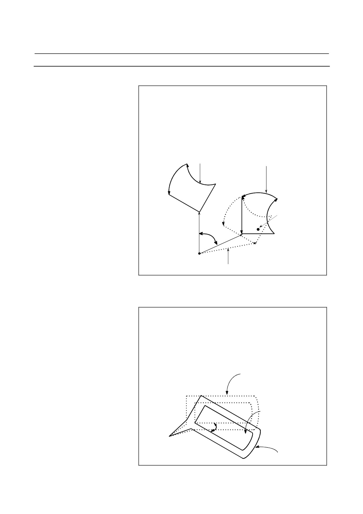
When parameter AX1 (No. 11600#5) = 1:
With the specification of (1), coordinates (X10,Y10) before
coordinate system rotation are converted to coordinates
(X'14.142,Y'0) in the coordinate system (X'Y') obtained by
45° rotation. Next, a movement is made to the specified
position
(X'14.142,Y'14.142), that is, the move position
(X0,Y20).
Specified position
: X'14.142,Y'14.142
Y
Move position
: X0,Y20
X'
Tool path
Coordinates before coordinate
system rotation is specified
Y'
: X10,Y10
●
Conversion
Coordinates in rotated coordinate
system
: X'14.142,Y'0
45°
X
- 227 -
6.COMPENSATION FUNCTION
PROGRAMMING
B-64304EN-2/01
Explanation
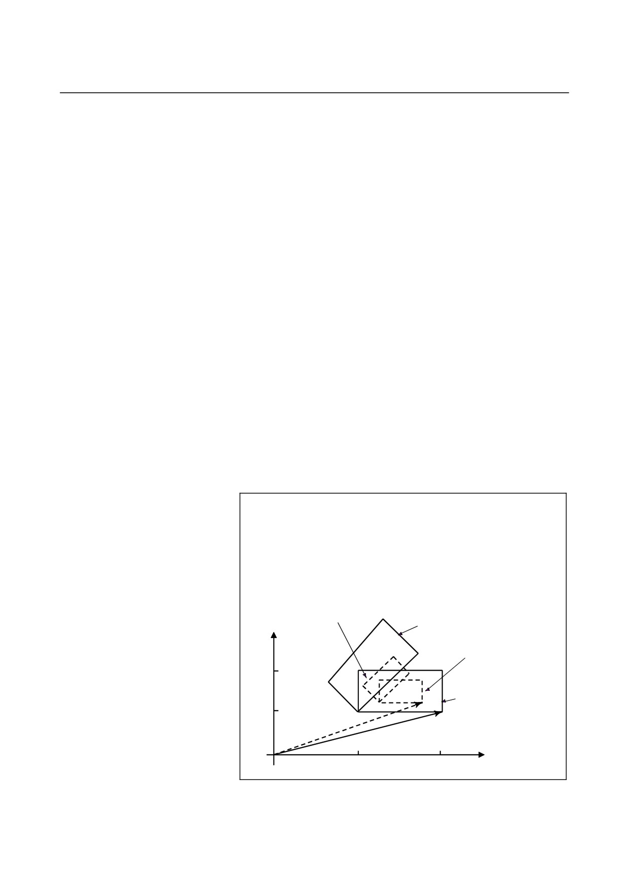
- Absolute/Incremental position commands
N1 G92 X-500.0 Y-500.0 G69 G17 ;
N2 G68 X700.0 Y300.0 R60.0 ;
N3 G90 G01 X0 Y0 F200 ;
(G91X500.0Y500.0)
N4 G91 X1000.0 ;
N5 G02 Y1000.0 R1000.0 ;
N6 G03 X-1000.0 I-500.0 J-500.0 ;
N7 G01 Y-1000.0 ;
N8 G69 G90 X-500.0 Y-500.0 M02 ;
Tool path when the incremental
command is designated in the N3
block (in parenthesis)
Originally programmed tool path
Center of rotation
(700.0,300.0)
(0,0)
60º
(-500.0,-500.0)
Tool path after rotation
Fig. 6.10 (c) Absolute/incremental programming during coordinate
system rotation
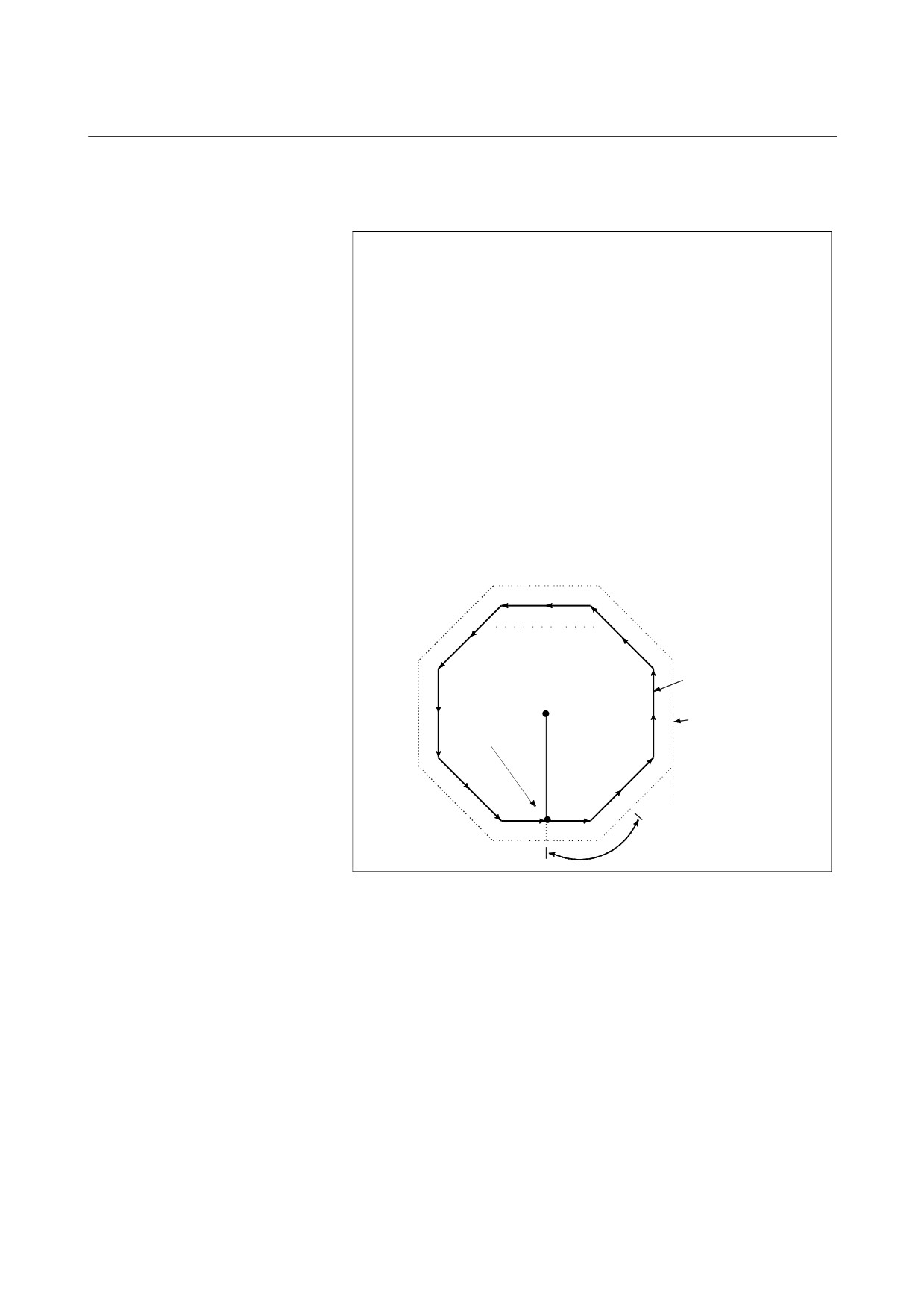
- Cutter compensation and coordinate system rotation
It is possible to specify G68 and G69 in cutter compensation mode.
The rotation plane must coincide with the plane of cutter compensation.
N1 G92 X0 Y0 G69 G01 ;
N2 G42 G90 X1000 Y1000 F1000 D01 ;
N3 G68 R-30000 ;
N4 G91 X2000 ;
N5 G03 Y1000 R1000 J500 ;
N6 G01 X-2000 ;
N7 Y-1000 ;
N8 G69 G40 G90 X0 Y0 M30 ;
Programmed shape before
coordinate system rotation
Programmed shape
after coordinate
system rotation
3
(0, 0)
Tool path
Fig. 6.10 (d) Cutter compensation and coordinate system rotation
- 228 -
B-64304EN-2/01
PROGRAMMING
6.COMPENSATION FUNCTION
- Scaling and coordinate system rotation
If a coordinate system rotation command is executed in the scaling
mode (G51 mode), the coordinate value (a, b) of the rotation center
will also be scaled, but not the rotation angle (R). When a move
command is issued, the scaling is applied first and then the
coordinates are rotated.
A coordinate system rotation command (G68) should not be issued in
cutter compensation mode (G41, G42) on scaling mode (G51). The
coordinate system rotation command should always be specified prior
to setting the cutter compensation mode.
1.
When the system is not in cutter compensation mode, specify the
commands in the following order :
G51 ;
Scaling mode start
G68 ;
Coordinate system rotation mode start
:
G69 ;
Coordinate system rotation mode cancel
G50 ;
Scaling mode cancel
2.
When the system is in cutter compensation, specify the
commands in the following order (Fig.6.10(e)) :
(cutter compensation cancel)
G51 ;
Scaling mode start
G68 ;
Coordinate system rotation start
:
G41 ;
Cutter compensation mode start
:
G92 X0 Y0 ;
G51 X300.0 Y150.0 P500 ;
G68 X200.0 Y100.0 R45.0 ;
G01 X400.0 Y100.0 ;
Y100.0 ;
X-200.0 ;
Y-100.0 ;
X200.0 ;
When scaling and coordinate
system rotation are applied
When only coordinate system
Y
rotation is applied
When only scaling is
applied
200.0
Cutting program
100.0
X
0
200.0
400.0
Fig. 6.10 (e) Scaling and coordinate system rotation in cutter
compensation mode
- 229 -
6.COMPENSATION FUNCTION
PROGRAMMING
B-64304EN-2/01
- Repetitive commands for coordinate system rotation
It is possible to store one program as a subprogram and recall
subprogram by changing the angle.
Sample program for when parameter RIN (No. 5400#0) is set to 1.
The specified angular displancement is treated as an absolute or
incremental value depending on the specified G code (G90 or G91).
G92 X0 Y0 G69 G17;
G01 F200 H01 ;
M98 P2100 ;
M98 P072200 ;
G00 G90 X0 Y0 M30 ;
O 2200 G68 X0 Y0 G91 R45.0 ;
G90 M98 P2100 ;
M99 ;
O 2100 G90 G01 G42 X0 Y-10.0 ;
X4.142 ;
X7.071 Y-7.071 ;
G40 ;
M99 ;
Programmed path
(0, 0)
When offset is
applied
(0, -10.0)
Subprogram
Fig. 6.10 (f) Coordinate system rotation command
- 230 -
B-64304EN-2/01
PROGRAMMING
6.COMPENSATION FUNCTION
6.11 NORMAL DIRECTION CONTROL (G40.1,G41.1,G42.1)
Overview
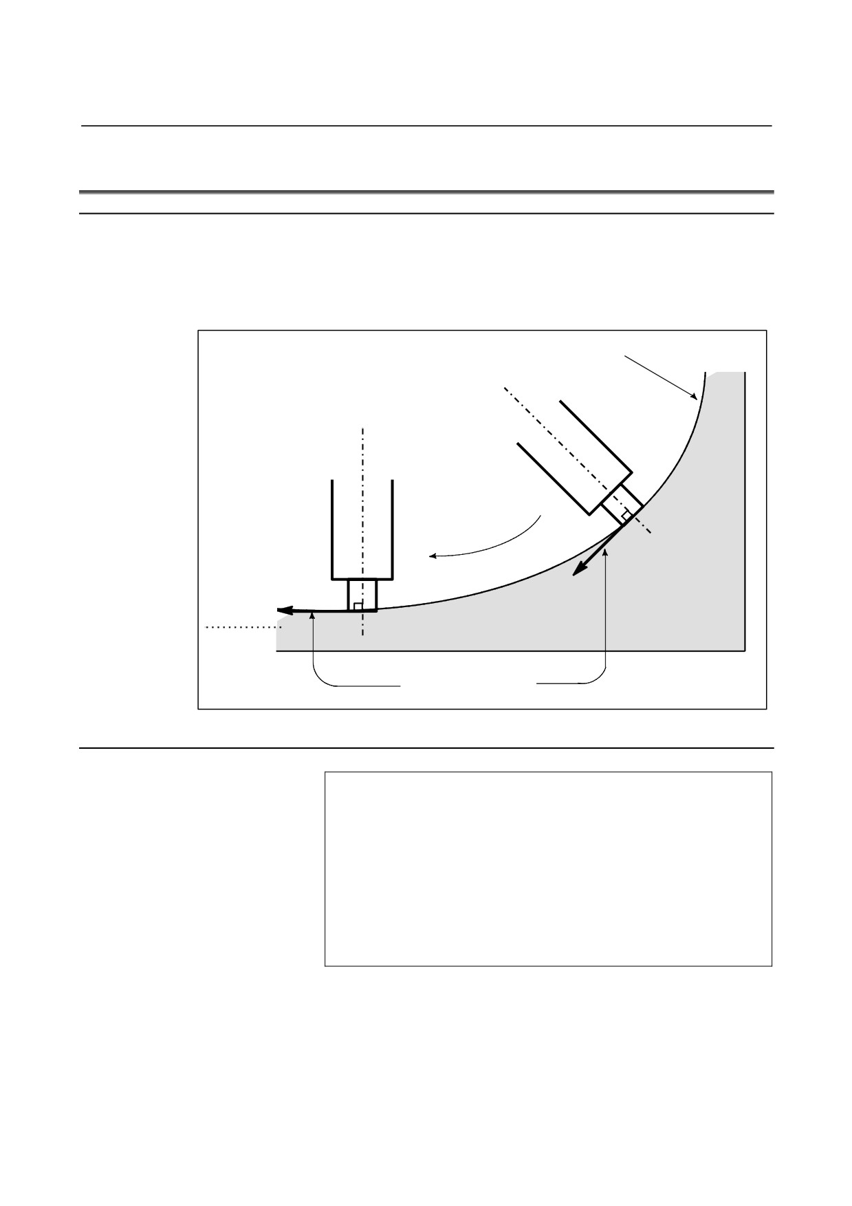
When a tool with a rotation axis (C-axis) is moved in the XY plane
during cutting, the normal direction control function can control the
tool so that the C-axis is always perpendicular to the tool path (Fig.
6.11 (a)).
Programmed tool path
C-axis
C-axis
Tool
Tool
Normal direction (in
which the tool moves)
Fig. 6.11 (a) Sample Movement of the tool
Format
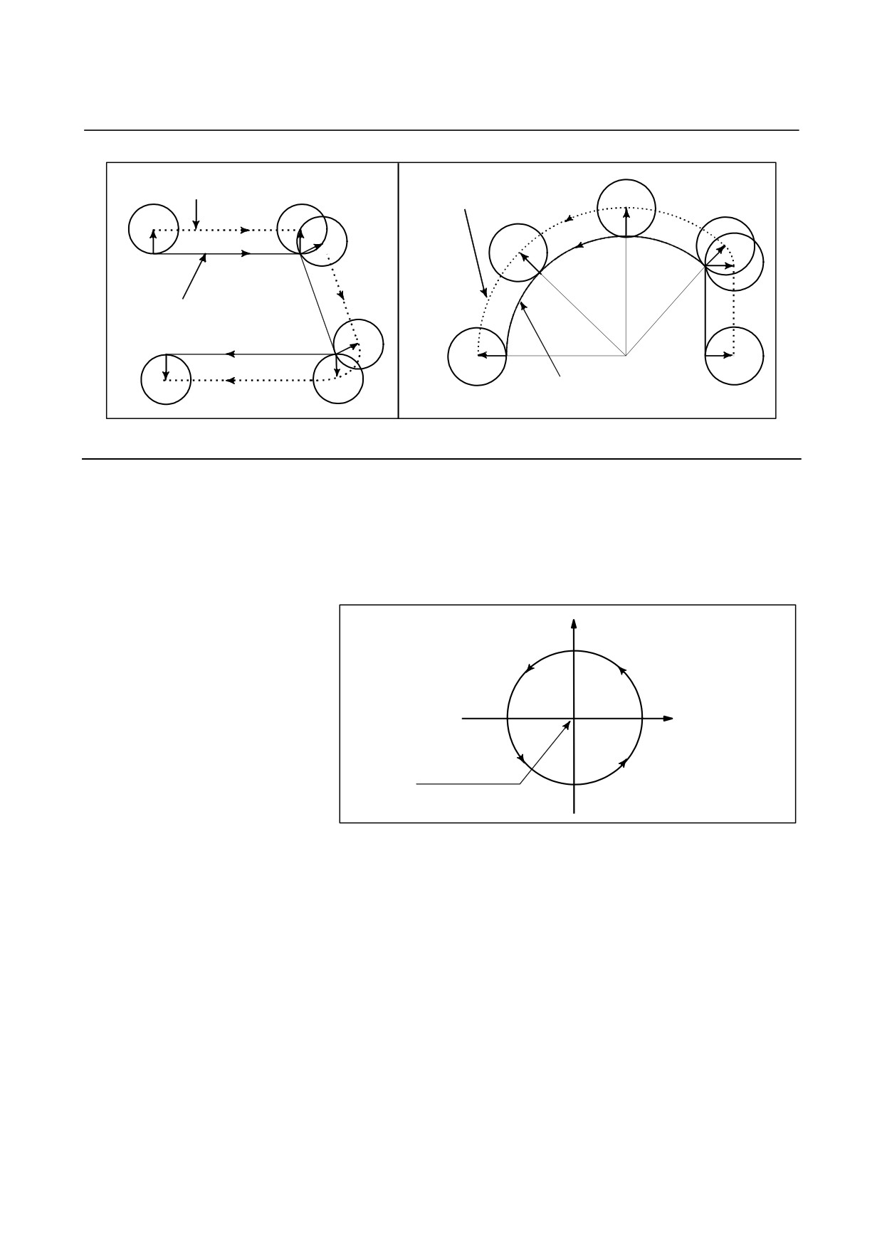
G41.1 ; Normal direction control, left
G42.1 ; Normal direction control, right
G40.1 ; Cancel normal direction control
The normal direction control, left (G41.1) command is
used when the workpiece is on the right side of the tool as
viewed while you are looking into the tool’s way.
Once either G41.1 or G42.1 is issued, normal direction
control is enabled (normal direction control mode).
Issuing G40.1 cancels the normal direction control mode.
- 231 -
6.COMPENSATION FUNCTION
PROGRAMMING
B-64304EN-2/01
Tool center path
Tool center path
Programmed tool path
Center of the arc
Programmed tool path
Fig. 6.11 (b) Normal direction control, left (G41.1) Fig. 6.11 (c) Normal direction control, right (G42.1)
Explanation
- Angle of the C axis
When viewed from the center of rotation around the C-axis, the
angular displacement about the C-axis is determined as shown in Fig.
6.11 (d). The positive side of the X-axis is assumed to be 0, the
positive side of the Y-axis is 90°, the negative side of the X-axis is
180°, and the negative side of the Y-axis is 270°.
+Y
90°
+X
180°
0°
Center of rotation
270°
Fig. 6.11 (d) Angle of the C axis
- Normal direction control of the C axis
When the cancel mode is switched to the normal direction control
mode, the C-axis becomes perpendicular to the tool path at the
beginning of the block containing G41.1 or G42.1.
In the interface between blocks in the normal direction control mode,
a command to move the tool is automatically inserted so that the
C-axis becomes perpendicular to the tool path at the beginning of each
block. The tool is first oriented so that the C-axis becomes
perpendicular to the tool path specified by the move command, then it
is moved along the X- and Y axes.
In the cutter compensation mode, the tool is oriented so that the C-axis
becomes perpendicular to the tool path created after compensation.
- 232 -
B-64304EN-2/01
PROGRAMMING
6.COMPENSATION FUNCTION
In single-block operation, the tool is not stopped between a command
for rotation of the tool and a command for movement along the X- and
Y-axes. A single-block stop always occurs after the tool is moved
along the X- and Y-axes.
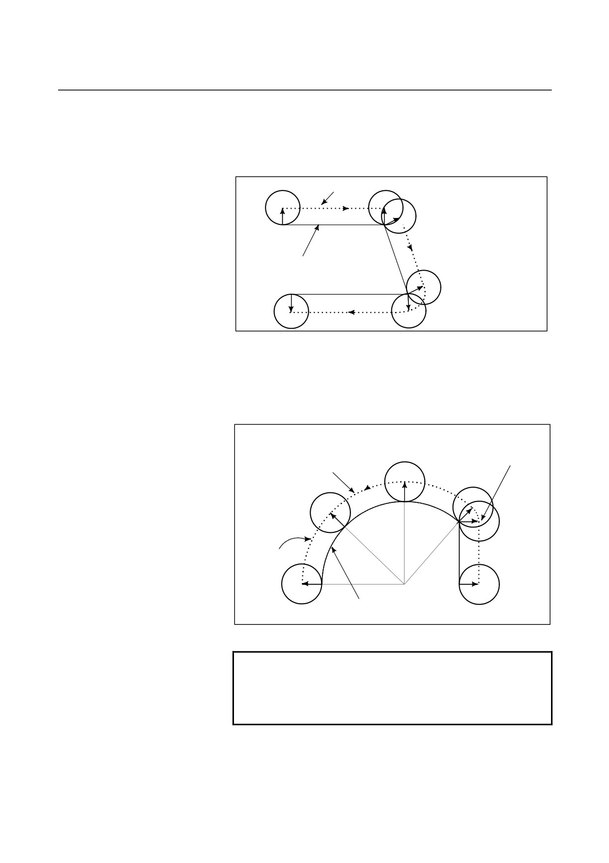
Tool center path
S
S
N1
S : Single block stop point
Programmed tool path
N2
S
S
N3
S
Fig. 6.11 (e) Point at which a single-block stop occurs in the normal
direction control mode
Before circular interpolation is started, the C-axis is rotated so that the
C-axis becomes normal to the arc at the start point. During circular
interpolation, the tool is controlled so that the C-axis is always
perpendicular to the tool path determined by circular interpolation.
The tool is controlled so that the C-axis
A rotation command is inserted so
is always normal to the tool path
that the C-axis becomes normal to
determined by circular interpolation.
the arc at the start point.
Tool center path
Center of the arc
Programmed tool path
Fig. 6.11 (f) Normal direction control of the circular interpolation
NOTE
During normal direction control, the C axis always
rotates through an angle less than 180 deg. I.e., it
rotates in whichever direction provides the shorter
route.
- 233 -
6.COMPENSATION FUNCTION
PROGRAMMING
B-64304EN-2/01
- C axis feedrate
Movement of the tool inserted at the beginning of each block is
executed at the feedrate set in parameter 5481. If dry run mode is on at
that time, the dry run feedrate is applied. If the tool is to be moved
along the X-and Y-axes in rapid traverse
(G00) mode, the rapid
traverse feedrate is applied.
The feedrate of the C axis during circular interpolation is defined by
the following formula.
Amount of movement of the C axis (deg)
F ×
(deg/min)
Length of arc (mm or inch)
F : Feedrate (mm/min or inch/min) specified by the corresponding
block of the arc
Amount of movement of the C axis :
The difference in angles at the beginning and the end of the
block.
NOTE
If the feedrate of the C axis exceeds the maximum
cutting speed of the C axis specified to parameter
No. 1430, the feedrate of each of the other axes is
clamped to keep the feedrate of the C axis below
the maximum cutting speed of the C axis.
- Normal direction control axis
A C-axis to which normal-direction control is applied can be assigned
to any axis with parameter No. 5480.
- Angle for which figure insertion is ignored
When the rotation angle to be inserted, calculated by normal-direction
control, is smaller than the value set with parameter No. 5482, the
corresponding rotation block is not inserted for the axis to which
normal-direction control is applied. This ignored rotation angle is
added to the next rotation angle to be inserted, the total angle being
subject to the same check at the next block.
If an angle of 360 degrees or more is specified, the corresponding
rotation block is not inserted.
If an angle of 180 degrees or more is specified in a block other than
that for circular interpolation with a C-axis rotation angle of
180
degrees or more, the corresponding rotation block is not inserted.
- 234 -
B-64304EN-2/01
PROGRAMMING
6.COMPENSATION FUNCTION
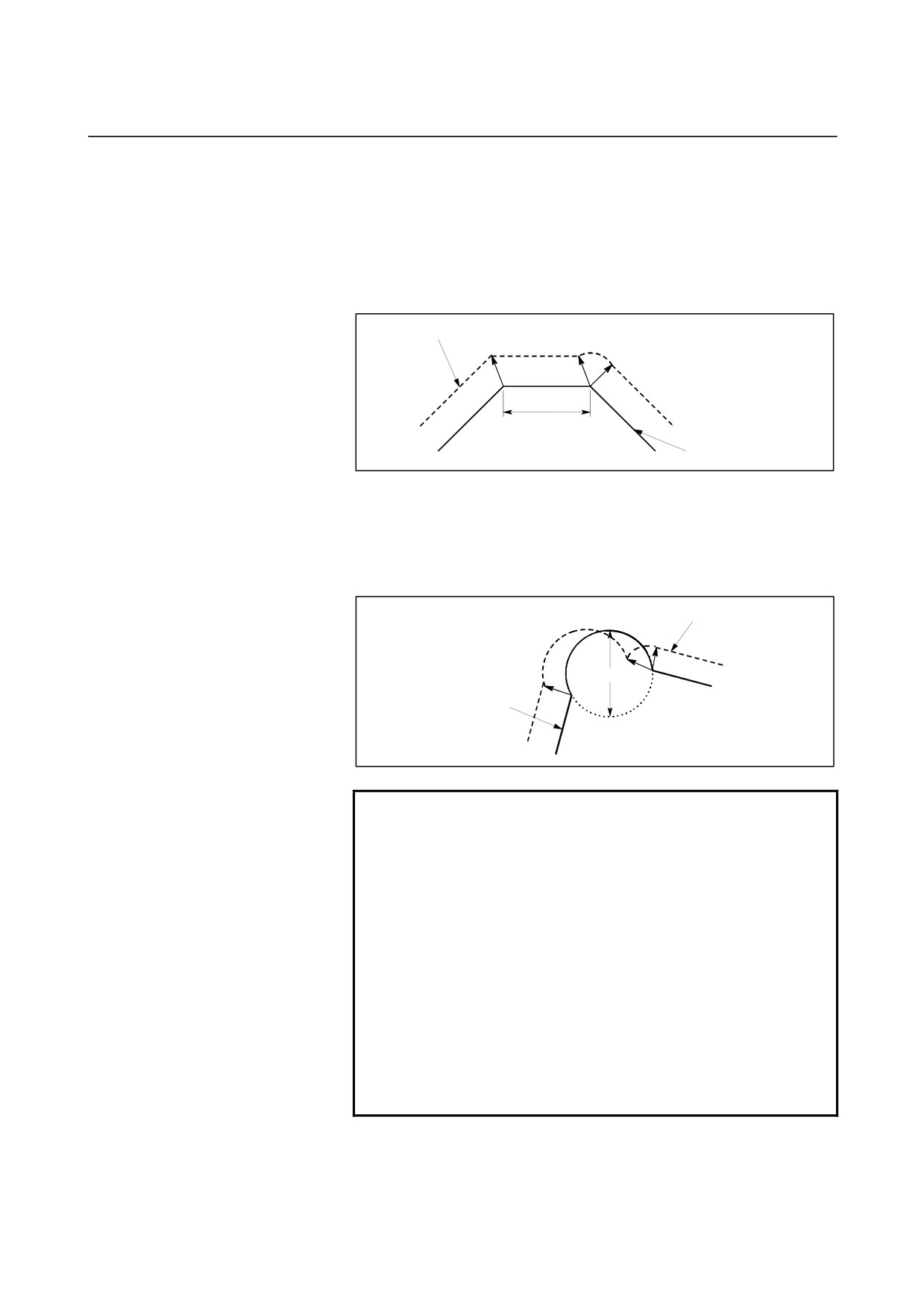
- Movement for which arc insertion is ignored
Specify the maximum distance for which machining is performed with
the same normal direction as that of the preceding block.
•
Linear movement
When distance N2, shown below, is smaller than the set value,
machining for block N2 is performed using the same direction as
that for block N1.
Tool center path
N2
N3
N1
Distance
Programmed tool path
•
Circular movement
When the diameter of block N2, shown below, is smaller than the
set value, machining for block N2 is performed using the same
normal direction as that for block N1. And control as
compensation along the circular arc is not performed.
Tool center path
N2
N3
Diameter
Programmed tool path
N1
NOTE
1 Do not specify any command to the C axis during
normal direction control. Any command specified at
this time is ignored.
2 Before processing starts, it is necessary to
correlate the workpiece coordinate of the C axis
with the actual position of the C axis on the
machine using the coordinate system setting (G92)
or the like.
3 The helical cutting option is required to use this
function. Helical cutting cannot be specified in the
normal direction control mode.
4 Normal direction control cannot be performed by
the G53 move command.
5 The C-axis must be a rotation axis.
- 235 -
6.COMPENSATION FUNCTION
PROGRAMMING
B-64304EN-2/01
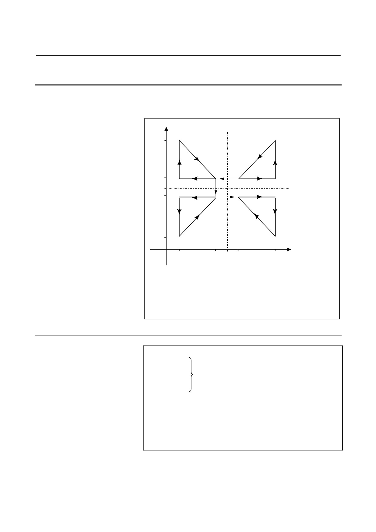
6.12 PROGRAMMABLE MIRROR IMAGE (G50.1, G51.1)
A mirror image of a programmed command can be produced with
respect to a programmed axis of symmetry (Fig. 15.3 (a)).
Y
Axis of symmetry (X=50)
(2)
(1)
100
60
Axis of symmetry
50
(Y=50)
40
0
(3)
(4)
0
40
50
60
100
X
(1) Original image of a programmed command
(2) Image symmetrical about a line parallel to the Y-axis and crossing the
X-axis at 50
(3) Image symmetrical about point (50, 50)
(4) Image symmetrical about a line parallel to the X-axis and crossing the
Y-axis at 50
Fig. 6.12 (a) Programmable mirror image
Format
G51.1 IP_ ; Setting a programmable image
:
A mirror image of a command specified in
:
these blocks is produced with respect to
:
the axis of symmetry specified by G51.1
:
IP_;.
G50.1 IP_ ; Canceling a programmable mirror image
IP_ : Point (position) and axis of symmetry for producing a
mirror image when specified with G51.1.
Axis of symmetry for producing a mirror image when
specified with G50.1. Point of symmetry is not
specified.
- 236 -
B-64304EN-2/01
PROGRAMMING
6.COMPENSATION FUNCTION
Explanation
- Mirror image by setting
If the programmable mirror image function is specified when the
command for producing a mirror image is also selected by a CNC
external switch or CNC setting
(see III-4.8 in User’s Manual
(Common to T/M series.)), the programmable mirror image function is
executed first.
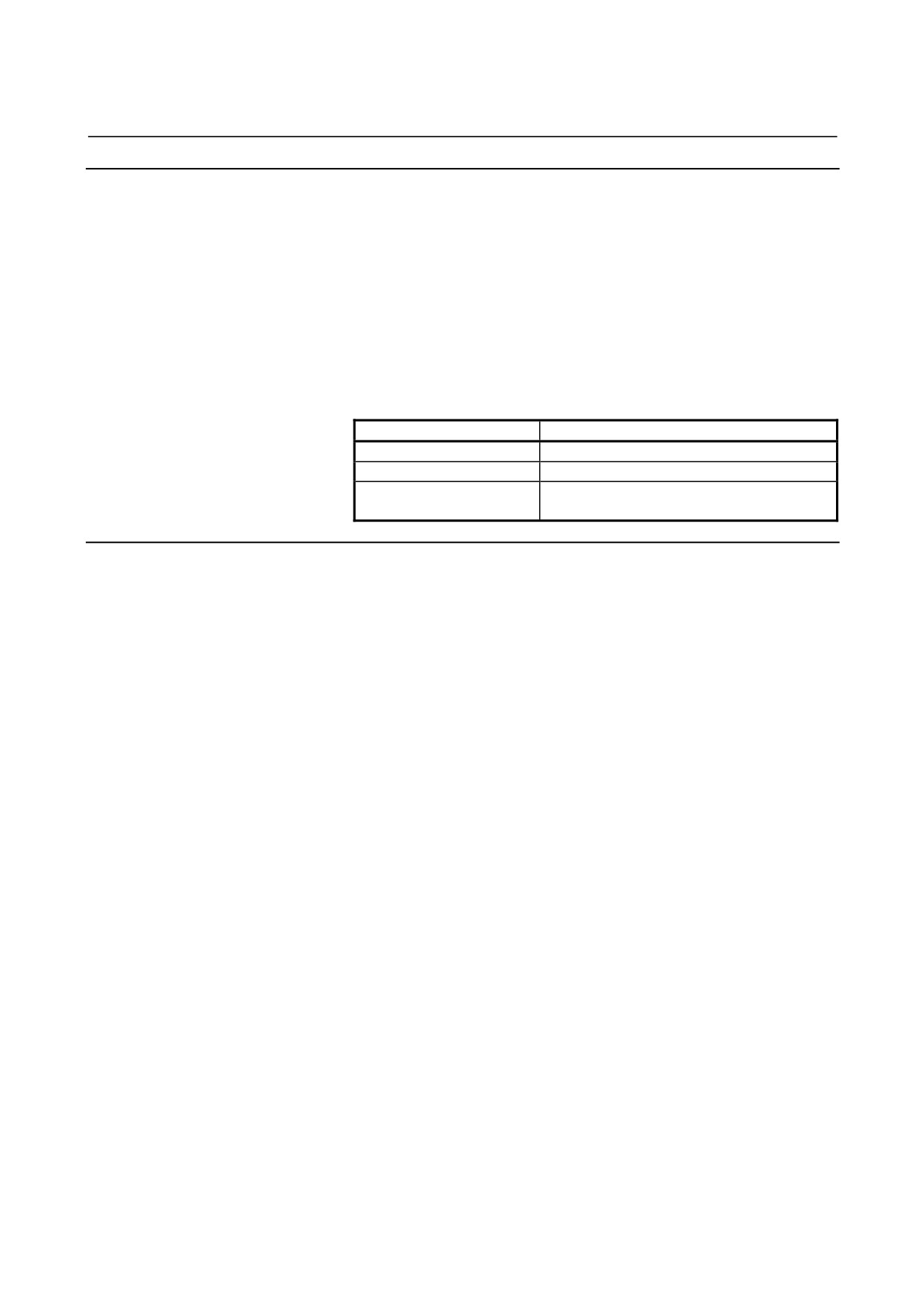
- Mirror image on a single axis in a specified plane
Applying a mirror image to one of the axes on a specified plane
changes the following commands as follows :
Command
Explanation
Circular command
G02 and G03 are interchanged.
Cutter compensation
G41 and G42 are interchanged.
CW and CCW (directions of rotation) are
Coordinate system rotation
interchanged.
Limitation
- Scaling and coordinate system rotation
Processing proceeds from program mirror image to scaling and
coordinate system rotation in the stated order. The commands should
be specified in this order, and, for cancellation, in the reverse order.
Do not specify G50.1 or G51.1 during scaling or coordinate system
rotation mode.
- Commands related to reference position return and coordinate system
In programmable mirror image mode, G codes related to reference
position return (G27, G28, G29, G30, etc.) and those for changing the
coordinate system (G52 to G59, G92, etc.) must not be specified. If
any of these G codes is necessary, specify it only after canceling the
programmable mirror image mode. If it is specified without
canceling the mode, the alarm PS0412 is issued.
- 237 -
7. MEMORY OPERATION USING
Series 10/11 FORMAT
PROGRAMMING
B-64304EN-2/01
7
MEMORY OPERATION USING Series
10/11 PROGRAM FORMAT
Overview
Memory operation of the program registered in Series 10/11 program
format is possible by setting the setting parameter FCV (No. 0001#1)
to 1.
Explanation
Data formats for tool radius compensation, subprogram call, and
canned cycles are different between the Series 0i and Series 10/11.
The Series 10/11 program formats can be processed for memory
operation.
Other data formats must comply with the Series 0i. When a value out
of the specified range for the Series 0i is registered, an alarm occurs.
Functions not available in the Series 0i cannot be used for memory
operation.
- Address for the tool radius compensation offset number
Offset numbers are specified by address D in the Series 10/11.
When an offset number is specified by address D, the modal value
specified by address H is replaced with the offset number specified by
address D.
- Subprogram call
If a subprogram number of more than four digits is specified, the four
low-order digits are regarded as the subprogram number.
If no repeat count is specified, 1 is assumed.
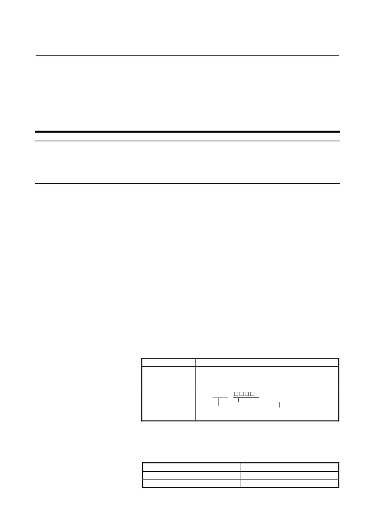
Table 7 (a) Subprogram call program format
CNC
Program format
M98 P{{{{ L{{{{
;
Series 10/11
P : Subprogram number
L : Repetition count (1 to 9999)
M98 P{{{
;
Series 0i
Repetition count Subprogram number
(1 to 9999)
- Address for the canned cycle repetition count for drilling
The Series 10/11 and this CNC use different addresses for the
canned cycle repetition count for drilling as listed in Table 7 (b).
Table 7 (b) Address for the canned cycle repetition count for drilling
CNC
Address
Series 10/11
L
Series 0i
K
- 238 -
B-64304EN-2/01
PROGRAMMING
8.AXIS CONTROL FUNCTIONS
8
AXIS CONTROL FUNCTIONS
Chapter
8, "AXIS CONTROL FUNCTIONS", consists of the
following sections:
8.1 ELECTRONIC GEAR BOX (G80, G81 (G80.4, G81.4))
240
- 239 -
8.AXIS CONTROL FUNCTIONS
PROGRAMMING
B-64304EN-2/01
8.1
ELECTRONIC GEAR BOX (G80, G81 (G80.4, G81.4))
8.1.1
Electronic Gear Box
Overview
This function synchronizes the revolutions of the workpiece axis
connected to the servo motor with the revolutions of the tool axis
(grinding stone/hob) connected to the spindle motor so as to machine
(grind/cut) gears as in the hobbing machine function.
The
synchronization ratio can be specified by a program.
Synchronization of the tool axis and the workpiece axis by this
function is directly controlled by a digital servo, so the workpiece axis
can track changes in the speed of the tool axis with no error, thereby
achieving high-precision machining of gears. In the following
descriptions, the electric gear box is called the EGB. For details on
the conditions that need be met to set the workpiece axis and tool axis,
refer to the manual provided by the machine tool builder.
NOTE
Electronic gear box is optional function.
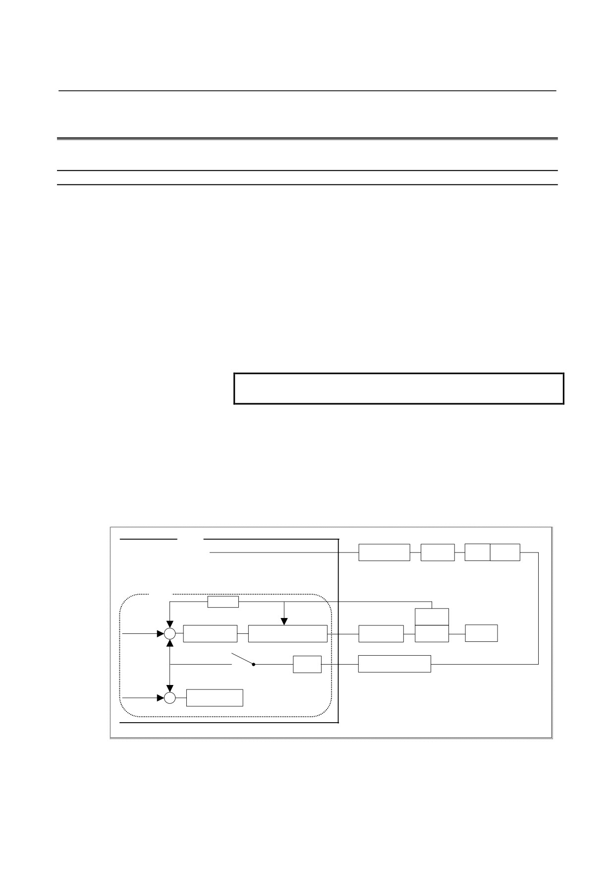
- Example of controlled axis configuration
Spindle
: EGB master axis : Tool axis
1st axis
: X axis
2nd axis : Y axis
3rd axis
: C axis (EGB slave axis : Workpiece axis)
4th axis
: C axis (EGB dummy axis : Cannot be used as a normal
controlled axis.)
CNC
Spindle (master axis)
Spindle amp.
Motor
Spindle
Detector
1st axis X (omitted)
Tool axis
2nd axis Y (omitted)
EGB
FFG
3rd axis C
-
slave axis
Detector
Position control
Velocity/current control
Servo amp.
Motor
C axis
+
Workpiece axis
+
K1
Separate detector
Sync switch
4th axis
-
dummy axis
K1: Sync coefficient
Error counter
Follow-up +
- 240 -
B-64304EN-2/01
PROGRAMMING
8.AXIS CONTROL FUNCTIONS
Format
Parameter EFX
Parameter EFX
(No.7731#0)=0
(No.7731#0)=1
Start of
G81 T_ ( L_ )
G81.4 T_ ( L_ )
synchronization
( Q_ P_ ) ;
( Q_ P_ ) ;
Cancellation of
G80 ;
G80.4 ;
synchronization
T : Number of teeth (Specifiable range: 1 to 1000)
L : Number of hob threads (Specifiable range: -200 to +200)
The sign of L determines the direction of rotation for the workpiece axis.
When L is positive, the direction of rotation for the workpiece axis is
positive (+ direction).
When L is negative, the direction of rotation for the workpiece axis is
negative (- direction).
When L is 0, it follows the setting of bit 3 (LZR) of parameter No.7701.
If L is not specified, the number of hob threads is assumed 1.
Q : Module or diametral pitch
Specify a module in the case of metric input.
(Unit: 0.00001mm, Specifiable range: 0.01 to 25.0mm)
Specify a diametral pitch in the case of inch input.
(Unit: 0.00001inch-1, Specifiable range: 0.01 to 254.0 inch-1)
P : Gear helix angle
(Unit: 0.0001deg, Specifiable range: -90.0 to 90.0deg)
When specifying Q and P, the user can use a decimal point.
NOTE
Specify G81, G80, G81.4, and G80.4 in a single
block.
Explanation
- Master axis, slave axis, and dummy axis
The synchronization reference axis is called the master axis, while the
axis along which movement is performed in synchronization with the
master axis is called the slave axis. For example, if the workpiece
moves in synchronization with the rotating tool as in a hobbing
machine, the tool axis is the master axis and the workpiece axis is the
slave axis.
Which axes to become the master and slave axes depends on the
configuration of the machine. For details, refer to the manual issued
by the machine tool builder.
A single servo axis is used exclusively so that digital servo can
directly read the rotation position of the master axis.
(This axis is
called the EGB dummy axis.)
- 241 -
8.AXIS CONTROL FUNCTIONS
PROGRAMMING
B-64304EN-2/01
- Synchronous control
(1)
Start of synchronization
If G81 is issued so that the machine enters synchronization mode,
the synch switch of the EGB function is closed, and the
synchronization of the tool and workpiece axes is started.
During synchronization, the rotation about the tool and
workpiece axes is controlled so that the relationship between T
(number of teeth) and L (number of hob threads) is maintained.
During synchronization, the synchronization relationship is
maintained regardless of whether the operation is automatic or
manual.
Specify P and Q to use helical gear compensation.
If only either P or Q is issued, alarm PS1594 is generated.
If, during synchronization, G81 is issued again without
synchronization cancellation, alarm PS1595 is generated if ECN,
bit 3 of parameter No. 7731, is 0. If ECN, bit 3 of parameter No.
7731, is
1, helical gear compensation is conducted with the
synchronization coefficient being changed to the one newly
specified with T and L commands if T and L commands are
issued, and if T and L commands are not issued and only P and Q
commands are issued, helical gear compensation is conducted
with the synchronization coefficient kept intact. This allows
consecutive fabrication of helical gears and super gears.
(2)
Start of tool axis rotation
When the rotation of the tool axis starts, the rotation of the
workpiece axis starts so that the synchronous relationship
specified in the G81 block can be maintained.
The rotation direction of the workpiece axis depends on the
rotation direction of the tool axis. That is, when the rotation
direction of the tool axis is positive, the rotation direction of the
workpiece axis is also positive; when the rotation direction of the
tool axis is negative, the rotation direction of the workpiece axis
is also negative. However, by specifying a negative value for L,
the rotation direction of the workpiece axis can be made opposite
to the rotation direction of the tool axis.
During synchronization, the machine coordinates of the
workpiece axis and EGB axis are updated as synchronous motion
proceeds. On the other hand, a synchronous move command
has no effect on the absolute and relative coordinates.
(3)
Termination of tool axis rotation
In synchronism with gradual stop of the tool axis, the workpiece
axis is decelerated and stopped. By specifying the command
below after the spindle stops, synchronization is canceled, and
the EGB synchronization switch is opened.
- 242 -
B-64304EN-2/01
PROGRAMMING
8.AXIS CONTROL FUNCTIONS
(4) Cancellation of synchronization
When cancellation of synchronization is issued, the absolute
coordinate on the workpiece axis is updated in accordance with
the amount of travel during synchronization. Subsequently,
absolute commands for the workpiece axis will be enabled.
For a rotation axis, the amount of travel during synchronization,
as rounded to
360-degree units is added to the absolute
coordinate.
In the G80 block, only O and N addresses can be specified.
By setting HBR, bit 0 of parameter No. 7700, to 0, it is possible
to cancel synchronization with a reset. If the manual absolute
switch is ON, the absolute coordinates are updated.
Synchronization is automatically canceled under the following
conditions:
<1> An emergency stop is applied.
<2> A servo alarm is generated.
<3> Alarm PW0000 (POWER MUST BE OFF) is generated.
<4> An IO alarm is generated.
CAUTION
1 Feed hold, interlock, and machine lock are invalid
to a slave axis in EGB synchronization.
2 Even if an OT alarm is issued for a slave axis in
EGB synchronization, synchronization will not be
canceled.
3 During synchronization, it is possible to execute a
move command for a slave axis and other axes,
using a program. The move command for a slave
command must be an incremental one.
- 243 -
8.AXIS CONTROL FUNCTIONS
PROGRAMMING
B-64304EN-2/01
NOTE
1
If bit 0 (HBR) of parameter No. 7700 is set to 1,
EGB synchronization will not be canceled due to a
reset. Usually, set this parameter bit to 1.
2
In synchronous mode, it is not possible to specify
G27, G28, G29, G30, and G53 for a slave axis.
3
It is not possible to use controlled axis detach for a
slave axis.
4
During synchronization, manual handle interruption
can be performed on the slave and other axes.
5
In synchronization mode, no inch/metric conversion
commands (G20 and G21) cannot be issued.
6
In synchronous mode, only the machine
coordinates on a slave axis are updated.
7
If bit 0 (EFX) of parameter No. 7731 is 0, no
canned cycle for drilling can be used. To use a
canned cycle for drilling, set bit 0 (EFX) of
parameter No. 7731 to 1 and use G81.4 instead of
G81 and G80.4 instead of G80.
8
If TDP, bit 0 of parameter No. 7702, is 1, the
permissible range of T is 0.1 to 100 (1/10 of the
specified value).
9
If, at the start of EGB synchronization (G81), L is
specified as 0, synchronization starts with L
assumed to be 1 if bit 3 (LZR) of parameter
No.7701, is 0; if bit 3 (LZR) of parameter No.7701,
is 1, synchronization is not started with L assumed
to be 0. At this time, helical gear compensation is
performed.
10 Feed per revolution is performed on the feedback
pulses on the spindle. By setting ERV, bit 0 of
parameter No. 7703, to 1, feed per revolution can
be performed based on the speed on the
synchronous slave axis.
11 Actual cutting feedrate display does not take
synchronization pulses into consideration.
12 In EGB synchronization mode, AI contour control
mode is temporarily canceled.
- 244 -
B-64304EN-2/01
PROGRAMMING
8.AXIS CONTROL FUNCTIONS
- Helical gear compensation
For a helical gear, the workpiece axis is compensated for the
movement along the Z-axis (axial feed axis) based on the torsion angle
of the gear.
Helical gear compensation is performed with the following formulas:
Z
×
sin(P)
Compensation angle =
×360 (for metric input)
π
×
T ×
Q
Z × Q × sin(P)
Compensation angle =
×360 (for inch input)
π
×
T
where
Compensation angle: Signed absolute value (deg)
Z :Amount of travel on the Z-axis after the specification of G81
P : Signed gear helix angle (deg)
π : Circular constant
T : Number of teeth
Q : Module (mm) or diametral pitch (inch-1)
Use P, T, and Q specified in the G81 block.
In helical compensation, the machine coordinates on the workpiece
axis and the absolute coordinates are updated with helical
compensation.
- 245 -
8.AXIS CONTROL FUNCTIONS
PROGRAMMING
B-64304EN-2/01
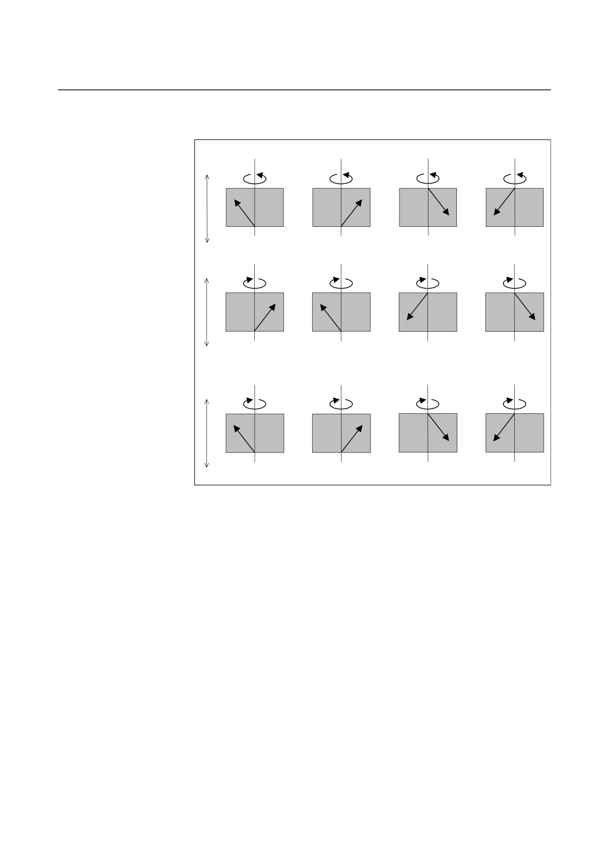
- Direction of helical gear compensation
The direction depends on HDR, bit 2 of parameter No. 7700.
When HDR is set to 1.
(a)
(b)
(c)
(d)
+Z
+C
+C
+C
+C
C:+, Z:+, P:+
C:+, Z:+, P:-
C:+, Z:-, P:+
C:+, Z:-, P:-
Compensation direction : +
Compensation direction : -
Compensation direction : -
Compensation direction : +
-Z
(e)
(f)
(g)
(h)
+Z
−C
−C
−C
−C
C:-, Z:+, P:+
C:-, Z:+, P:-
C:-, Z:-, P:+
C:-, Z:-, P:-
Compensation direction : -
Compensation direction : +
Compensation direction : +
Compensation direction : -
-Z
When HDR is set to 0. (In (a), (b), (c), and (d), the same as that if HDR is 1)
(e)
(f)
(g)
(h)
+Z
−C
−C
−C
−C
C:-, Z:+, P:+
C:-, Z:+, P:-
C:-, Z:-, P:+
C:-, Z:-, P:-
Compensation direction : +
Compensation direction : -
Compensation direction : -
Compensation direction : +
-Z
- Synchronization coefficient
A synchronization coefficient is internally represented using a fraction
(Kn/Kd) to eliminate an error. The formula below is used for
calculation.
K
L ȕ
Synchronization coefficient = n
=
×
Kd
T
Į
where
L : Number of hob threads
T : Number of teeth
α : Number of pulses of the position detector per rotation about the
master axis (parameter No. 7772)
β : Number of pulses of the position detector per rotation about the
slave axis (parameter No. 7773)
Kn / Kd is a value resulting from reducing the right side of the above
formula, but the result of reduction is subject to the following
restrictions:
-2147483648≤Kn≤2147483647
1≤Kd≤65535
When this restriction is not satisfied, the alarm (PS1596) is issued
when G81 is specified.
- 246 -
B-64304EN-2/01
PROGRAMMING
8.AXIS CONTROL FUNCTIONS
Example
O1000 ;
N0010 M19 ;
Tool axis orientation
N0020 G28 G91 C0 ;
Reference position return on the workpiece
axis
N0030 G81 T20 L1 ;
Synchronous start on tool and workpiece
axes
(Rotation about the workpiece axis by
18° per rotation about the tool axis)
N0040 S300 M03 ;
Rotation about the tool axis at 300min-1
N0050 G01 X F
;
Movement along the X-axis (cut)
N0060 G01 Z F
;
Movement along the Z-axis (machining)
-----------------------------;
If necessary, axis commands such as C, X,
and Z commands are allowed.
N0100 G01 X F
;
Movement along the X-axis (escape)
N0110 M05 ;
Stop on the tool axis
N0120 G80 ;
Synchronous cancellation on tool and
workpiece axes
N0130 M30 ;
- 247 -
8.AXIS CONTROL FUNCTIONS
PROGRAMMING
B-64304EN-2/01
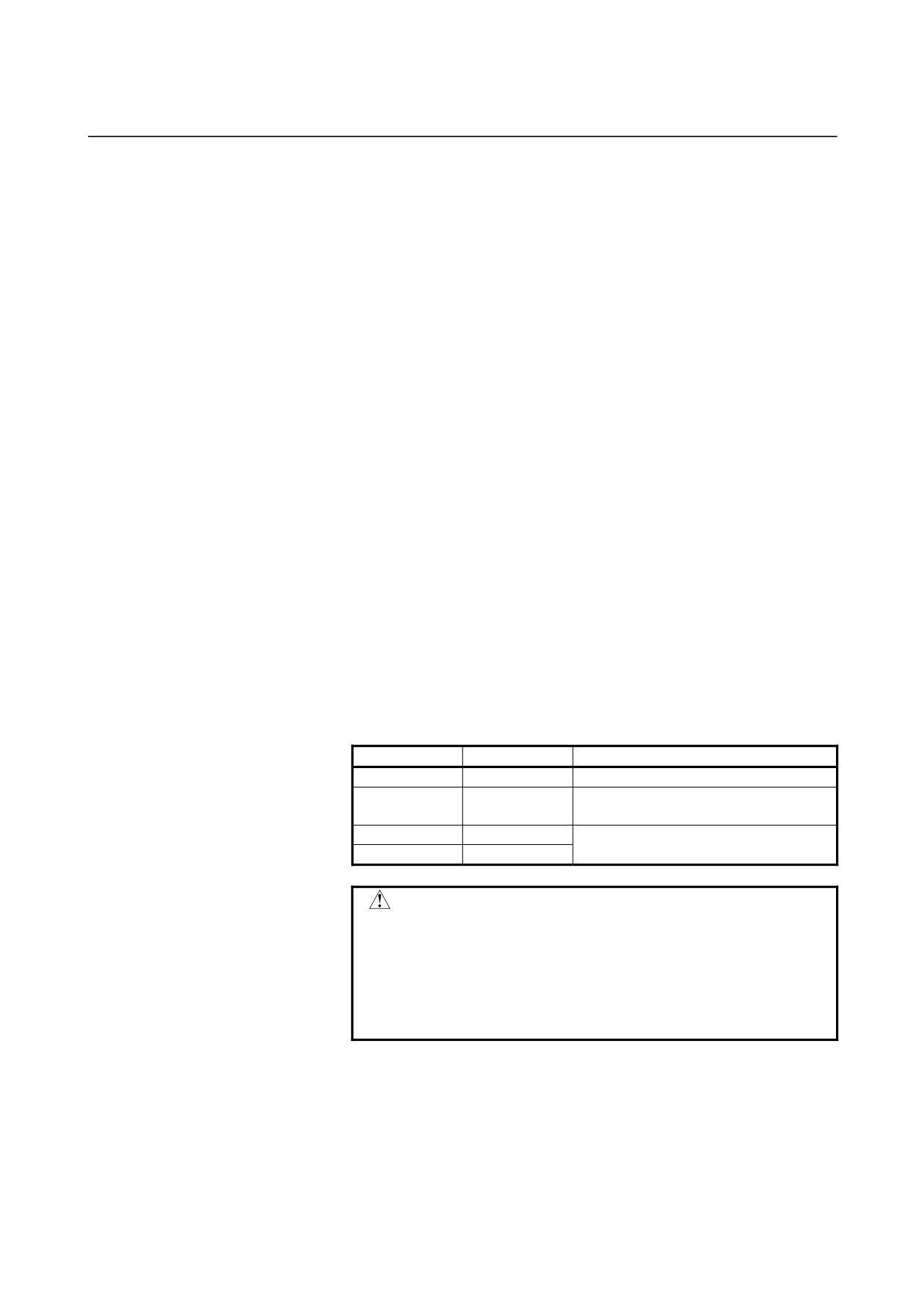
- Retract function
(1) Retract function with an external signal
When the retract switch on the machine operator’s panel is
turned on, retraction is performed with the retract amount set in
parameter No. 7741 and the feedrate set in parameter No. 7740.
No movement is performed along an axis for which 0 is set as the
retract amount.
For the retract switch, refer to the relevant manual provided by
the machine tool builder.
(2) Retract function with an alarm
If, during EGB synchronization or automatic operation, a CNC
alarm is issued, retraction is performed with the retract amount
set in parameter No. 7741 and the speed set in parameter No.
7740.
This can prevent the tool and the object being machined from
damage if a servo alarm is generated.
No movement is performed along an axis for which 0 is set as the
retract amount.
For the retract switch, refer to the relevant manual provided by
the machine tool builder.
Conditions under the retract function with an alarm
The conditions under which the retract function with a servo or
spindle alarm can be changed using the settings of ARE, bit 1 of
parameter No. 7703, and bit 2 (ARO) of parameter No. 7703.
The table below lists parameter settings and corresponding
conditions.
ARE
ARO
Condition
1
0
EGB synchronization is in progress.
Both EGB synchronization and
1
1
automatic operation are in progress.
0
0
Either EGB synchronization or
0
1
automatic operation is in progress.
CAUTION
1 Retraction is performed at the speed specified in
parameter No. 7740.
2 Feed hold is not effective to movement during
retraction.
3 Feedrate override is not effective to movement
during retraction.
- 248 -
B-64304EN-2/01
PROGRAMMING
8.AXIS CONTROL FUNCTIONS
NOTE
1
During a retract operation, an interlock is effective
to the retract axis.
2
During a retract operation, a machine lock is
effective to the retract axis.
3
The retraction direction depends on the movement
direction of the machine, regardless of whether an
mirror image (signal and setting) is enabled or
disabled. (No mirror image can be applied to the
updating of absolute coordinates.)
4
If retraction is performed during automatic
operation, automatic operation is halted
simultaneously with a retract operation, but it is at
the end of the retract operation that the operation
state switches to the automatic operation halt state.
5
It is not possible to perform automatic operation
during retraction.
6
The acceleration/deceleration of a retract operation
is in the acceleration/deceleration state at the start
of retraction.
7
Retract movement is performed with non-linear
type positioning.
8
If, during a retract operation, a reset or an
emergency stop is made, the operation is
interrupted.
9
If, during a retract operation on multiple axes, an
OT alarm or a malfunction prevention alarm is
issued for a retract axis, the operation stops only
on the axis for which the alarm is issued if bit 4
(RTS) of parameter No. 7731 is 0. If bit 4 (RTS) of
parameter No. 7731 is 1, the retract operation is
interrupted on all axes. If a servo alarm or non-axis
malfunction prevention alarm is issued, the retract
operation is interrupted on all axes regardless of
the setting of bit 4 (RTS) of parameter No. 7731.
10 To enable the retract function with an alarm, bit 3
(ART) of parameter No.7702, must be set.
11 The retract function with an alarm does not perform
a retract operation on the retract axis if an overtravel
alarm or a servo alarm is generated on the retract
axis.
12 If a new alarm is issued during retraction with the
retract function with an alarm, a retract operation is
not performed.
- 249 -
B-64304EN-2/01
OPERATION
1.SETTING AND DISPLAYING DATA
1
SETTING AND DISPLAYING DATA
Chapter 1, "SETTING AND DISPLAYING DATA", consists of the
following sections:
1.1 SCREENS DISPLAYED BY FUNCTION KEY
.........254
1.1.1 Setting and Displaying the Tool Compensation Value 254
1.1.2 Tool Length Measurement
258
- 253 -
1.SETTING AND DISPLAYING DATA OPERATION
B-64304EN-2/01
1.1
SCREENS DISPLAYED BY FUNCTION KEY
Press function key
to display or set tool compensation values
and other data.
This section explains how to display and specify the following:
1. Tool compensation value
2. Tool length measurement
Refer to the User’s Manual (Common to Lathe System/Machining
Center System) (B-64304EN) for explanations about how to display
or specify the other types of data.
- 254 -
B-64304EN-2/01
OPERATION
1.SETTING AND DISPLAYING DATA
1.1.1
Setting and Displaying the Tool Compensation Value
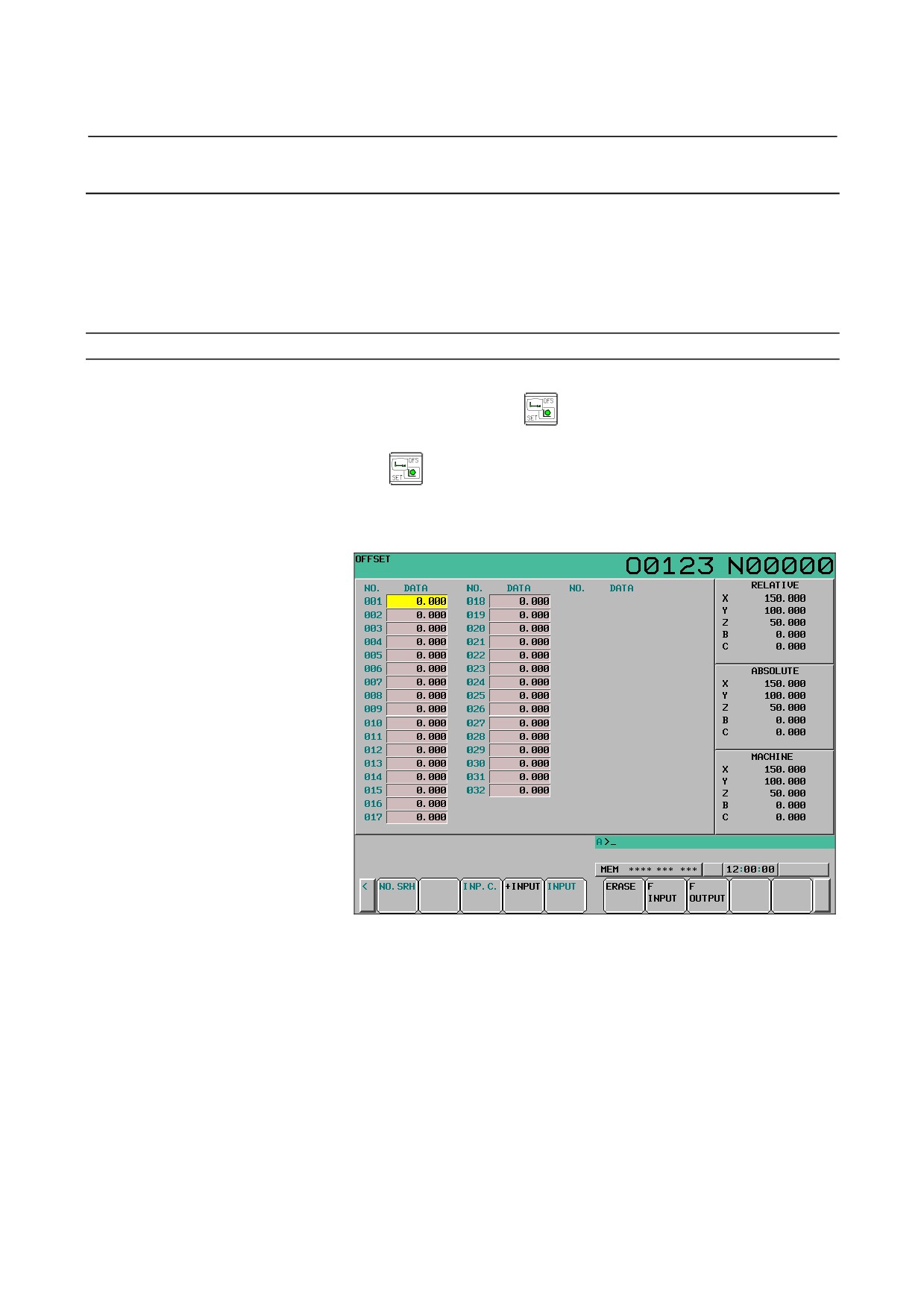
Tool offset values, tool length compensation values, and cutter
compensation values are specified by D codes or H codes in a
program. Compensation values corresponding to D codes or H codes
are displayed or set on the screen.
There are two tool offset memory types, A and C.
Procedure for setting and displaying the tool compensation value
Procedure
1
Press function key
2
Press chapter selection soft key [OFFSET] or press function key
several times until the tool compensation screen is
displayed.
The screen varies according to the type of tool compensation
memory.
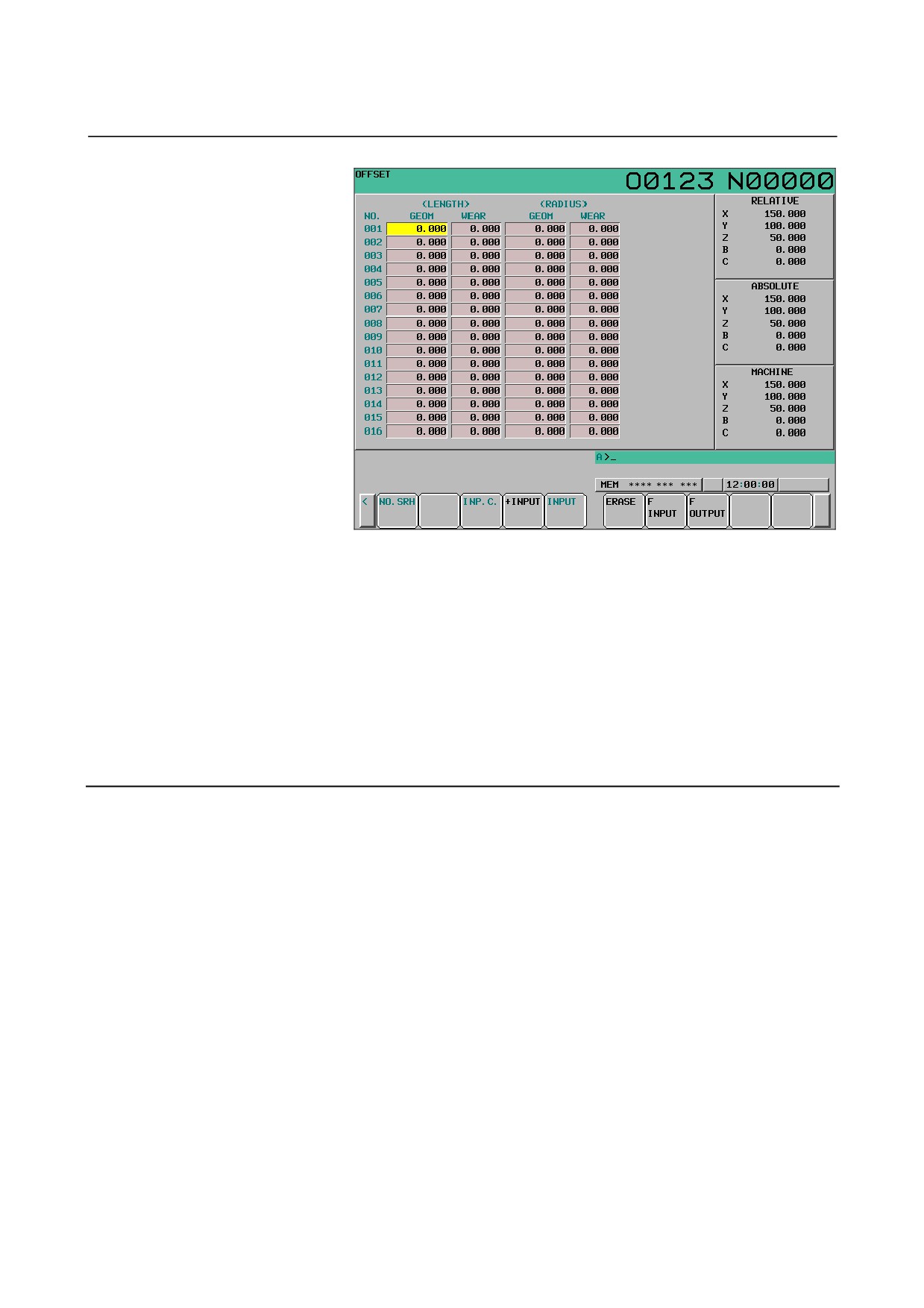
Fig. 1.1.1 (a) Tool compensation memory A (10.4-inch)
- 255 -
1.SETTING AND DISPLAYING DATA OPERATION
B-64304EN-2/01
Fig. 1.1.1 (b) Tool compensation memory C (10.4-inch)
3
Move the cursor to the compensation value to be set or changed
using page keys and cursor keys, or enter the compensation
number for the compensation value to be set or changed and
press soft key [NO.SRH].
4
To set a compensation value, enter a value and press soft key
[INPUT].
To change the compensation value, enter a value to add to the
current value (a negative value to reduce the current value) and
press soft key [+INPUT]. Or, enter a new value and press soft
key [INPUT].
Explanation
- Decimal point input
A decimal point can be used when entering a compensation value.
- Other setting method
An external input/output device can be used to input or output a tool
offset value. See Chapter III-8 in User’s Manual (Common to T/M). A
tool length compensation value can be set by measuring the tool
length as described in the next subsection.
- Tool compensation memory
There are tool compensation memories A and C, which are classified
as follows:
Tool compensation memory A
D codes and H codes are treated the same. Tool geometry
compensation and tool wear compensation are treated the same.
Tool compensation memory C
D codes and H codes are treated differently. Tool geometry
compensation and tool wear compensation are treated differently.
- 256 -
B-64304EN-2/01
OPERATION
1.SETTING AND DISPLAYING DATA
Bit 6 (NGW) of parameter No. 8136 can be used to specify whether to
use tool offset memory C ("0" for specifying to use it and "1" for
specifying not to use it). If tool offset memory C is not used, tool
offset memory A is used.
- Number of tool offset values
Bit 5 (NDO) of parameter No. 8136 can be used to specify whether to
use 400 tool offset values ("0" for specifying to use 400 tool offset
values and "1" for specifying not to use them). If the number of tool
offset values to be used is not 400, the number of tool offset values to
be used is 32.
- Disabling entry of compensation values
The entry of compensation values may be disabled by setting bit 0
(WOF) and bit 1 (GOF) of parameter No.3290 (not applied to tool
compensation memory A).
In this case, it is possible to prohibit any range of tool offset values
from being entered from the MDI by setting the start tool offset value
number in parameter No. 3294 and the quantity of offset values
counted from the beginning of the range in parameter No.3295.
If an attempt is made to enter tool offset values including those
prohibited, the following occur:
1)
When compensation values are input consecutively from offset
numbers for which the input of values is enabled to offset
numbers for which the input of values is inhibited, a warning is
issued, but the compensation values in the range of the offset
numbers for which the input of values is enabled are set.
2)
When compensation values are input consecutively from offset
numbers for which the input of values is inhibited to offset
numbers for which the input of values is enabled, a warning is
issued and the compensation values are not set.
- 257 -
1.SETTING AND DISPLAYING DATA OPERATION
B-64304EN-2/01
1.1.2
Tool Length Measurement
The length of the tool can be measured and registered as the tool
length compensation value by moving the reference tool and the tool
to be measured until they touch the specified position on the machine.
The tool length can be measured along the X-, Y-, or Z-axis.
Bit 7 (NTL) of parameter No. 8136 can be used to specify whether to
use tool length measurement ("0" for specifying to use it and "1" for
specifying not to use it).
Procedure for tool length measurement
Procedure
1
Use manual operation to move the reference tool until it touches
the specified position on the machine (or workpiece.)
2
Press function key
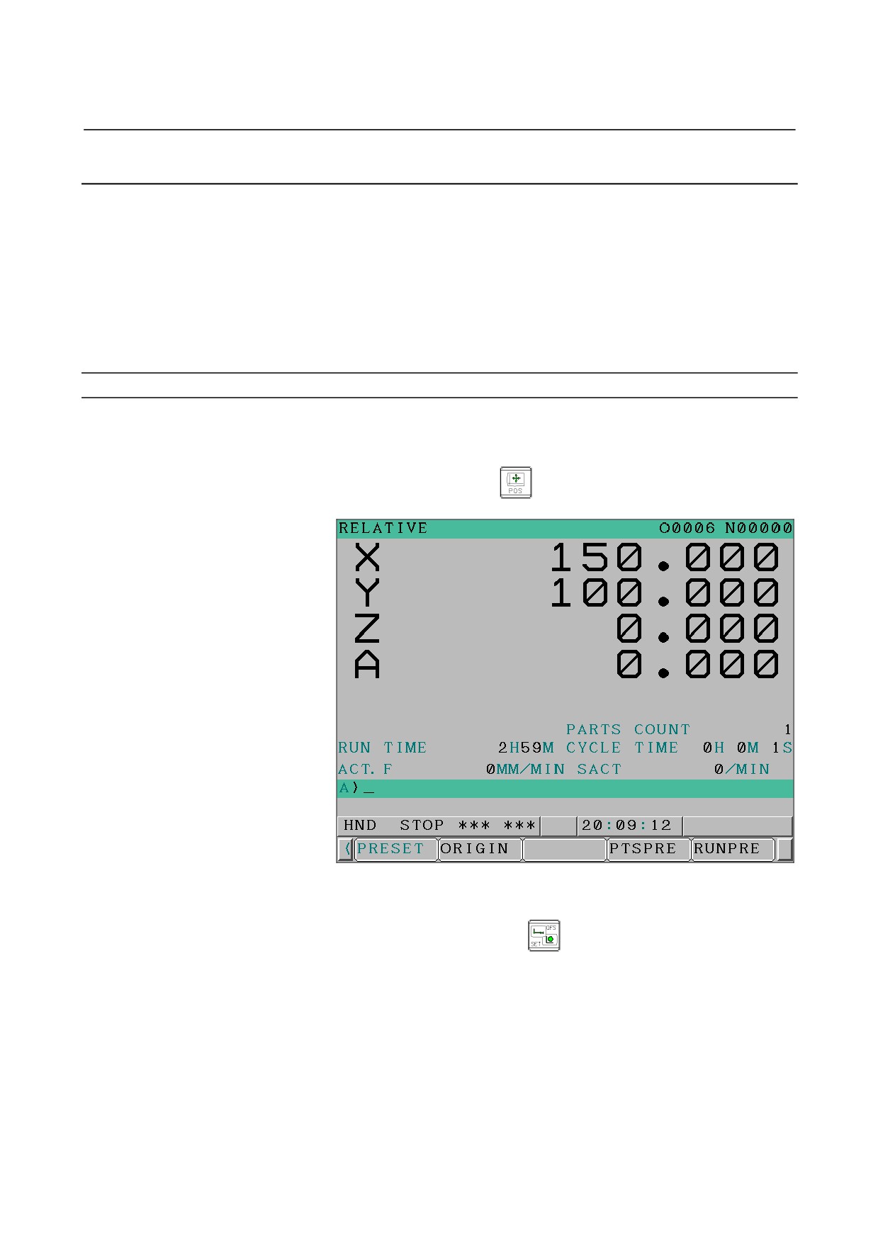
several times until the current position
display screen with relative coordinates is displayed.
Fig. 1.1.2 (a) Current position display screen (8.4-inch)
3
Reset the relative coordinate for the Z-axis to 0.
4
Press function key
several times until the tool
compensation screen is displayed.
5
Use manual operation to move the tool to be measured until it
touches the same specified position. The difference between the
length of the reference tool and the tool to be measured is
displayed in the relative coordinates on the screen.
6
Move the cursor to the compensation number for the target tool
(the cursor can be moved in the same way as for setting tool
compensation values).
- 258 -