FANUC Series 0i-MODEL F. For Lathe System OPERATOR'S MANUAL (B-64604EN-1/01) - page 22
 

  Index      Manuals     FANUC Series 0i-MODEL F. For Lathe System OPERATOR'S MANUAL (B-64604EN-1/01)


Search            copyright infringement  


Content      ..     20      21      22      23     ..


FANUC Series 0i-MODEL F. For Lathe System OPERATOR'S MANUAL (B-64604EN-1/01) - page 22


 B-64604EN-1/01

 OPERATION 

2.SETTING AND DISPLAYING DATA


- 331 - 


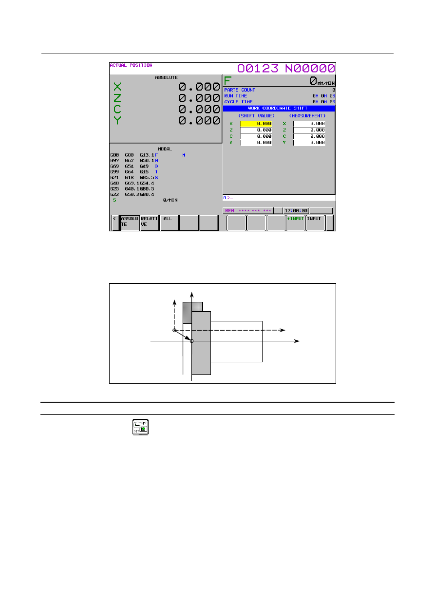
Fig. 2.1.5 (a) Workpiece coordinate system shift screen (10.4-inch display unit) 


Press soft key [W.SHFT]. 

Move the cursor using cursor keys to the axis along which the coordinate system is to be shifted. 

Enter the shift value and press soft key [INPUT]. 

X

Z

X’

Z’

O

O’

Shift


Fig. 2.1.5 (b)   


Setting the workpiece coordinate system shifting amount (for 15-inch display unit) 

Press function key 

Press vertical soft key [NEXT PAGE] several times until vertical soft key [WORK SHIFT] is 
displayed. 


2.SETTING AND DISPLAYING DATA

 OPERATION 

 B-64604EN-1/01


- 332 - 


Fig. 2.1.5 (c) Workpiece coordinate system shift screen (15-inch display unit) 


Press vertical soft key [WORK SHIFT]. 

Move the cursor using cursor keys to the axis along which the coordinate system is to be shifted. 

Enter the shift value and press horizontal soft key [INPUT]. 

X

Z

X’ 

Z’

O

O’ 

Shift 


Fig. 2.1.5 (d)   


Direct input of coordinate system shift 

If the tool position assumed at programming is inputted when the coordinate system actually set is 
different from the workpiece coordinate system assumed at programming, shift length of the coordinate 
system actually set and the workpiece coordinate system assumed at programming is set in the workpiece 
coordinate system shift value. 
The procedure leading up to inputting coordinate system position depend on the setting made for bit 2 
(PRC) of parameter No.5005. 
The procedure in which the coordinate system position of workpiece end face is specified is as follows. 
 

When bit 2 (PRC) of parameter No.5005 is set to 0 

Cut the workpiece end face tentatively. 

Display the workpiece coordinate system shift screen with touching tool to the workpiece end face. 

Move the cursor to Z axis of MEASUREMENT. 

Input the workpiece end face position on workpiece coordinate system assumed at programming and 
press soft key [INPUT]. 


 B-64604EN-1/01

 OPERATION 

2.SETTING AND DISPLAYING DATA


- 333 - 

When bit 2 (PRC) of parameter No.5005 is set to 1 

Cut the workpiece end face tentatively. 

Set the position record signal PRC to "1" with touching tool to the workpiece end face. (Refer to the 
appropriate manual provided by the machine tool builder for the actual operations.) 

Remove a tool from the workpiece end face. 

Display the workpiece coordinate system shift screen. 

Move the cursor to Z axis of MEASUREMENT. 

Input the workpiece end face position on workpiece coordinate system assumed at programming and 
press soft key [INPUT]. 


Fig.2.1.5 (e)    Direct input of coordinate system shift 


Explanation 

  - 

When shift values become valid 

Shift values become valid immediately after they are set. 
 

  - 

Shift values and coordinate system setting command 

Setting a command (G50 or G92) for setting a coordinate system disables the set shift values. 
Example) 
 

When G50 X100.0 Z80.0; is specified, the coordinate system is set so that the current tool reference 
position is X+100.0, Z+80.0 regardless of the shift values. 


  - 

Shift values and coordinate system setting 

If the automatic coordinate system setting is performed by manual reference position return after shift 
amount setting, the coordinate system is shifted instantly. 
 

  - 

Diameter or radius value 

Whether the shift amount on the X-axis is diameter or radius value depends on that specified in program. 
 

  - 

Position record signal 

When bit 2 (PRC) of parameter No. 5005 is 1, the absolute coordinates when the position record signal 
PRC is “1” are recorded for calculation of the shift amount. 
 

2.SETTING AND DISPLAYING DATA

 OPERATION 

 B-64604EN-1/01


- 334 - 

Example 

When the actual position of the reference point is X=121.0 (diameter), Z=69.0 with respect to the 
workpiece origin but it should be X=120.0, Z=70.0, set the following shift values: 
X=1.0, Z=-1.0 

Start position
(Standard position)


Fig. 2.1.5 (f)   


2.1.6 

Setting Tool Offset / 2nd Geometry Tool Offset Values 

To compensate for a difference in tool attachment position or selection position, second geometry tool 
offset can be applied in addition to tool offset. As second geometry tool offset values, X-axis, Y-axis, and 
Z-axis offset values can be set. 
 

NOTE 


"2nd Geometry Tool Offset" is an optional function. 
To use the "2nd Geometry Tool Offset", this option and "Tool geometry offset 
and Tool wear offset" are required. "Tool geometry offset and Tool wear offset" 
can be used, when bit 6 (NGW) of parameter No.8136 is 0. 


Procedure for displaying and setting second geometry tool offset values (for 
8.4/10.4-inch display unit) 

Procedure 

Press function key 

Press the continuous menu key 

  several times until the screen with soft key [2ND GEOM] is 

displayed. 

Press the soft key [2ND GEOM]. The tool offset/second geometry tool offset screen is displayed. 
When displaying data other than the data of the second geometry tool offset number currently 

displayed, press the page key 

 or 

  to display the screen for a desired second geometry 

tool offset number. 

 B-64604EN-1/01

 OPERATION 

2.SETTING AND DISPLAYING DATA


- 335 - 


Fig. 2.1.6 (a) Tool offset/second geometry tool offset screen (10.4-inch display unit) 

 
3-1  If one screen cannot fully display the second geometry tool offset values of the Y-axis, press the soft 

key [SWITCH] to switch the screen display. 


Fig. 2.1.6 (b) Tool offset/second geometry tool offset screen (after switching) (10.4-inch display unit) 


By using one of the methods described below, move the cursor to the second geometry tool offset 
value of a desired second geometry tool offset number. 


By using the page keys and cursor keys, move the cursor to the desired offset value position. 


Key in the desired offset number then press soft key [NO.SRH]. 

Input a desired second geometry tool offset value then press the 

  key or soft key [INPUT]. 

The input second geometry tool offset value is set. When an additional offset to the second geometry 
tool offset value currently displayed is input, press soft key [+INPUT]. In this case, the result of 
addition is set as the second geometry tool offset value. 

Repeat steps 4 and 5 to set all parameters to be modified. 


2.SETTING AND DISPLAYING DATA

 OPERATION 

 B-64604EN-1/01


- 336 - 

Procedure for displaying and setting second geometry tool offset values (for 
15-inch display unit) 

Press function key 

Press vertical soft key [NEXT PAGE] several times until vertical soft key [2ND GEOM] is 
displayed. 

Press the vertical soft key [2ND GEOM]. The tool offset/second geometry tool offset screen is 
displayed. When displaying data other than the data of the second geometry tool offset number 

currently displayed, press the page key 

 or 

  to display the screen for a desired second 

geometry tool offset number. 


Fig. 2.1.6 (c) Tool offset/second geometry tool offset screen (15-inch display unit) 


By using one of the methods described below, move the cursor to the second geometry tool offset 
value of a desired second geometry tool offset number. 


By using the page keys and cursor keys, move the cursor to the desired offset value position. 


Key in the desired offset number then press horizontal soft key [NO.SRH] . 

Input a desired second geometry tool offset value then press the 

  key or horizontal soft key 

[INPUT]. The input second geometry tool offset value is set. When an additional offset to the second 
geometry tool offset value currently displayed is input, press soft key [+INPUT]. In this case, the 
result of addition is set as the second geometry tool offset value. 

Repeat steps 4 and 5 to set all offset value to be modified. 


Explanation 

  - 

Input of a second geometry tool offset value 

The value input in the key input buffer is set as the second geometry tool offset value where the cursor is 
currently placed. 
 

  - 

+Input of a second geometry tool offset value 

The value input in the key input buffer is added to the second geometry tool offset value where the cursor 
is currently placed. 
 

 B-64604EN-1/01

 OPERATION 

2.SETTING AND DISPLAYING DATA


- 337 - 

  - 

Number search for a second geometry tool offset value 

The value input in the key input buffer is used as a second geometry tool offset number to move the 
cursor to the corresponding position. 
 

Limitation 

Setting of a second geometry tool offset value 

The setting of a second geometry tool offset value is valid only when bit 5 (GO2) of parameter No. 3290 
is set to 1. 
 

2.1.7 

Setting the Y-Axis Offset 

The Y-axis offset corresponding to each tool offset number is displayed, and can to set it. 
When the tool geometry offset and tool wear offset functions are enabled and bit 4 (YGW) of parameter 
No. 11349 is set to 0 (operation 1), the display can be switched between the tool geometry and wear 
offset screens using soft key [CHANGE]. When these functions are enabled and bit 4 (YGW) of 
parameter No. 11349 is set to 1 (operation 2), the display can be switched between the tool geometry and 
wear offset screens using soft keys [WEAR] and [GEOMETRY]. 
 

NOTE 


The Y-axis offset is available, when bit 1 (YOF) of parameter No.8132 is 1. 


Operation 1 


Procedure for setting the tool offset value of the Y axis (for 8.4/10.4-inch display 
unit) 

Press function key 

Press the continuous menu key 

  several times until the screen with soft key [Y OFFSET] is 

displayed. 

Press soft key [Y OFFSET]. The Y-axis offset screen is displayed. 


Fig. 2.1.7 (a) Y-axis offset screen (10.4-inch display unit) 


3-1  When the tool geometry offset and wear offset functions are enabled, press soft key [(OPRT)] 

and continuous menu key 

. Soft key [CHANGE] appears. Press soft key [CHANGE]. 

2.SETTING AND DISPLAYING DATA

 OPERATION 

 B-64604EN-1/01


- 338 - 

Y-axis tool geometry offset data is displayed. Press soft key [CHANGE] again. The display 
changes to the tool wear offset screen. 


Fig. 2.1.7 (b) Y-axis offset screen (tool geometry) (10.4-inch display unit) 


Position the cursor at the offset number to be changed by using either of the following methods: 


Move the cursor to the offset number to be changed using page keys and cursor keys. 


Type the offset number and press soft key [NO.SRH]. 

Enter the offset value. 

Press soft key [INPUT]. The offset value is set and displayed. 


Fig. 2.1.7 (c) Y-axis offset screen (input) (10.4-inch display unit) 


Procedure for setting the tool offset value of the Y axis (for 15-inch display unit) 

Press function key 

Press vertical soft key [NEXT PAGE] several times until vertical soft key [Y OFFSET] is displayed. 

Press vertical soft key [Y OFFSET]. The Y-axis offset screen is displayed. 

 B-64604EN-1/01

 OPERATION 

2.SETTING AND DISPLAYING DATA


- 339 - 


Fig. 2.1.7 (d) Y-axis offset screen (15-inch display unit) 


3-1  When horizontal soft key [CHANGE] is pressed, Y-axis tool geometry offset data is displayed. 

Press the horizontal soft key [CHANGE] again to switch the screen display to the display of 
tool wear offset data. 


Fig. 2.1.7 (e) Y-axis offset screen (tool geometry)(15-inch display unit) 


Position the cursor at the offset number to be changed by using either of the following methods: 


Move the cursor to the offset number to be changed using page keys and cursor keys. 


Type the offset number and press horizontal soft key [NO.SRH]. 

Enter the offset value. 

Press horizontal soft key [INPUT]. The offset value is set and displayed. 


2.SETTING AND DISPLAYING DATA

 OPERATION 

 B-64604EN-1/01


- 340 - 


Fig. 2.1.7 (f) Y-axis offset screen (input)(15-inch display unit) 


Operation 2 

When the tool geometry offset and wear offset functions are enabled and bit 4 (YGW) of parameter No. 
11349 is set to 1, the display can be switched between the tool geometry and wear offset screens using 
soft keys [WEAR] and [GEOMETRY]. Vertical soft keys [WEAR] and [GEOMETRY] can also be used 
to switch the display between these screens. 
 

Procedure for setting the tool offset value of the Y axis (for 8.4/10.4-inch display 
unit) 

Press function key 

Press the continuous menu key 

  several times until the screen with soft key [Y OFFSET] is 

displayed. 

Press soft key [Y OFFSET]. The Y-axis offset screen is displayed. 


Fig. 2.1.7 (g) Y-axis offset screen (wear) (10.4-inch display unit) 

 B-64604EN-1/01

 OPERATION 

2.SETTING AND DISPLAYING DATA


- 341 - 

 
3.1  Press soft key [(OPRT)] and continuous menu key 

. Soft key [GEOMETRY] appears. 

Press soft key [GEOMETRY] to display tool geometry offset data. Press soft key [WEAR] to 
display tool wear offset data. 


Fig. 2.1.7 (h) Y-axis offset screen (tool geometry) (10.4-inch display unit) 


Position the cursor at the offset number to be changed by using either of the following methods: 


Move the cursor to the offset number to be changed using page keys and cursor keys. 


Type the offset number and press soft key [NO.SRH]. 

Enter the offset value. 

Press soft key [INPUT]. The offset value is set and displayed. 


Fig. 2.1.7 (i) Y-axis offset screen (input) (10.4-inch display unit) 


2.SETTING AND DISPLAYING DATA

 OPERATION 

 B-64604EN-1/01


- 342 - 

Procedure for setting the tool offset value of the Y axis (for 15-inch display unit) 

Press function key 

Press vertical soft key [NEXT PAGE] several times until vertical soft key [Y OFFSET] is displayed. 

Press vertical soft key [Y OFFSET]. The Y-axis offset screen is displayed. 


Press vertical soft key [WEAR] to display tool wear offset data. Press vertical soft key 
[GEOMETRY] to display tool geometry offset data. 


Fig. 2.1.7 (j) Y-axis offset screen (wear) (15-inch display unit) 


Fig. 2.1.7 (k) Y-axis offset screen (tool geometry)(15-inch display unit) 


Position the cursor at the offset number to be changed by using either of the following methods: 


Move the cursor to the offset number to be changed using page keys and cursor keys. 


Type the offset number and press horizontal soft key [NO.SRH]. 

Enter the offset value. 

Press horizontal soft key [INPUT]. The offset value is set and displayed. 


 B-64604EN-1/01

 OPERATION 

2.SETTING AND DISPLAYING DATA


- 343 - 


Fig. 2.1.7 (l) Y-axis offset screen (input) (15-inch display unit) 


Procedure for counter input of the offset value (for 8.4/10.4-inch display unit) 

To set relative coordinates along the Y-axis as offset values: 

Move the reference tool to the reference point. 

Reset relative coordinate Y to 0. 

Move the tool for which offset values are to be set to the reference point. 

Move the cursor to the value for the offset number to be set, press 

  key, then press soft key 

[INP.C.]. 


Relative coordinate Y (or V) is now set as the offset value. 


Procedure for counter input of the offset value (for 15-inch display unit) 

To set relative coordinates along the Y-axis as offset values: 

Move the reference tool to the reference point. 

Reset relative coordinate Y to 0. 

Move the tool for which offset values are to be set to the reference point. 

Move the cursor to the value for the offset number to be set, press 

  key, then press horizontal 

soft key [INP.C.]. 


Relative coordinate Y (or V) is now set as the offset value. 


2.1.8 

Setting the 4th/5th Axis Offset 

NOTE 


"4th/5th axis offset" is an optional function. 

 
By the operation described below, the 4th/5th axis offset screen can be displayed. 
 

Procedure for displaying and setting 4th/5th axis offset values (for 8.4/10.4-inch 
display unit) 

Procedure 

Press function key 

2.SETTING AND DISPLAYING DATA

 OPERATION 

 B-64604EN-1/01


- 344 - 

Press the continuous menu key 

  several times until soft key [EXTEND OFFSET] is displayed. 

Press soft key [EXTEND OFFSET] to display the 4th/5th axis offset screen. The number of tool 
offset values depends varies according to the number of added tool offset pairs. When the tool 
geometry offset function and tool wear offset function are used, soft keys [GEOMETRY] and 
[WEAR] are displayed. 


Fig. 2.1.8 (a) 4th/5th axis offset screen (without tool geometry/wear offset) (10.4inch) 


Pressing soft key [WEAR] displays tool wear offset values.  Pressing soft key [GEOMETRY] 
displays tool geometry offset values. 


Fig. 2.1.8 (b) 4th/5th axis offset screen (with tool geometry/wear offset) (10.4inch) 


Pressing soft key [(OPRT)] displays soft keys [NO.SRH], [+INPUT], [INPUT], [ERASE], [F 
INPUT], and [F OUTPUT]. 


 B-64604EN-1/01

 OPERATION 

2.SETTING AND DISPLAYING DATA


- 345 - 


Fig. 2.1.8 (c) 4th/5th axis offset screen (operation)(10.4inch) 


Procedure for displaying and setting 4th/5th axis offset values (for 15-inch display 
unit) 

Procedure 

Press function key 

Press vertical soft key [NEXT PAGE] several times until vertical soft key [EXTEND OFFSET] is 
displayed. 

Press vertical soft key [EXTEND OFFSET] to display the 4th/5th axis offset screen. The number of 
tool offset values depends varies according to the number of added tool offset sets. When the tool 
geometry offset function and tool wear offset function are used, horizontal soft keys [GEOMETRY] 
and [WEAR] are displayed. 


Fig. 2.1.8 (d) 4th/5th axis offset screen (without tool geometry/wear offset) (15-inch display unit) 


2.SETTING AND DISPLAYING DATA

 OPERATION 

 B-64604EN-1/01


- 346 - 

Pressing horizontal soft key [WEAR] displays tool wear offset values.    Pressing horizontal soft key 
[GEOMETRY] displays tool geometry offset values. 
Moreover, soft keys [NO.SRH], [+INPUT], [INPUT], [ERASE], [F INPUT], and [F OUTPUT] are 
displayed. 


Fig. 2.1.8 (e) 4th/5th axis offset screen (with tool geometry/wear offset) (15-inch display unit) 


Displaying tool offset values (for 8.4/10.4-inch display unit) 

A tool offset value can be displayed using the procedure below. 
 

Procedure 

By using the page keys and cursor keys, move the cursor to a tool offset value to be displayed. 

Type the tool offset value number to be displayed then press soft key [NO.SRH]. 


Setting tool offset values (for 8.4/10.4-inch display unit) 

A tool offset value can be set or modified by using the procedure below. 
 

Procedure 

To set a tool offset value, move the cursor to the tool offset value position to be changed. Next, type 

the desired offset value then press MDI key 

To set a tool offset value, move the cursor to the tool offset value position to be changed. Next, type 
the desired offset value then press soft key [INPUT]. 

To modify a tool offset value, type a desired incremental or decremental value then press soft key 
[+INPUT]. 


Displaying tool offset values (for 15-inch display unit) 

A tool offset value can be displayed using the procedure below. 
 

Procedure 

By using the page keys and cursor keys, move the cursor to a tool offset value to be displayed. 

Type the tool offset value number to be displayed then press horizontal soft key [NO.SRH]. 


Content      ..     20      21      22      23     ..