FANUC Series 16i / 18i / 160i / 180i - Model A. Maintenance Manual (B-63005EN/01) - page 14
A. ALARM LIST
APPENDIX
B-63005EN/01
Number
Message
Contents
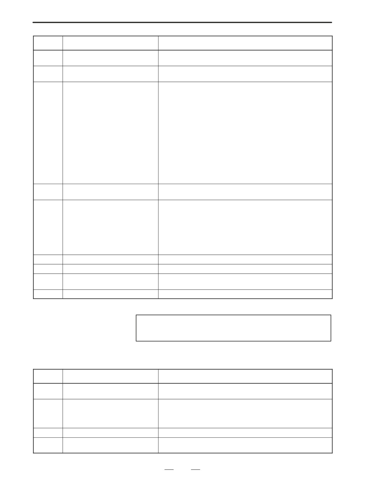
5117
SPL : ERROR
The first control point of NURBS is incorrect.
(M series)
5118
SPL : ERROR
After manual intervention with manual absolute mode set to on, NURBS
(M series)
interpolation was restarted.
5122
ILLEGAL COMMAND IN SPIRAL
A spiral interpolation or conical interpolation command has an error.
(M series)
Specifically, this error is caused by one of the following:
1) L = 0 is specified.
2) Q = 0 is specified.
3) R/, R/, C is specified.
4) Zero is specified as height increment.
5) Three or more axes are specified as the height axes.
6) A height increment is specified when there are two height axes.
7) Conical interpolation is specified when the helical interpolation
function is not selected.
8) Q < 0 is specified when radius difference > 0.
9) Q > 0 is specified when radius difference < 0.
10) A height increment is specified when no height axis is specified.
5123
OVER TOLERANCE OF END POINT
The difference between a specified end point and the calculated end
(M series)
point exceeds the allowable range (parameter 3471).
5124
CAN NOT COMMAND SPIRAL
A spiral interpolation or conical interpolation was specified in any of the
(M series)
following modes:
1) Scaling
2) Programmable mirror image
3) Polar coordinate interpolation
In cutter compensation C mode, the center is set as the start point or
end point.
5134
FSSB : OPEN READY TIME OUT
Initialization did not place FSSB in the open ready state.
5135
FSSB : ERROR MODE
FSSB has entered error mode.
5136
FSSB : NUMBER OF AMPS IS SMALL
In comparison with the number of controlled axes, the number of amplifi-
ers recognized by FSSB is not enough.
5137
FSSB : CONFIGURATION ERROR
FSSB detected a configuration error.
NOTE
HPCC : High precision contour control
(2) Program errors/Alarms on program and operation (P/S alarm)
Number
Message
Contents
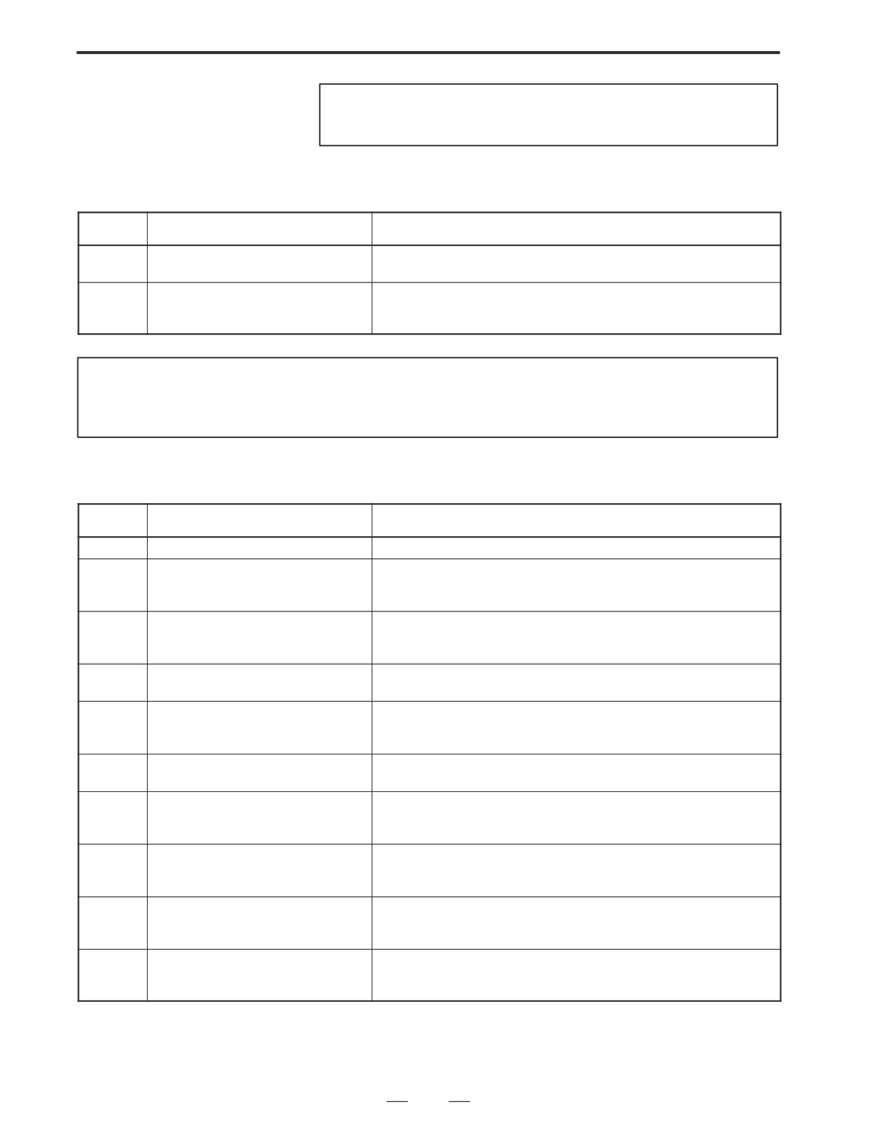
5138
FSSB : AXIS SETTING NOT COM-
In automatic setting mode, axis setting has not been made yet.
PLETE
Perform axis setting on the FSSB setting screen.
5156
ILLEGAL AXIS OPERATION
In simple high-precision contour control mode, the controlled axis
(SHPCC)
selection signal (PMC axis control) changes.
(M series)
In simple high-precision contour control mode, the simple synchronous
axis selection signal changes.
5197
FSSB : OPEN TIME OUT
The CNC permitted FSSB to open, but FSSB was not opened.
5198
FSSB : ID DATA NOT READ
Temporary assignment failed, so amplifier initial ID information could not
be read.
382
B-63005EN/01
APPENDIX
A. ALARM LIST
NOTE
SHPCC stands for simple high-precision contour control.
(3) Background edit alarm
Number
Message
Contents
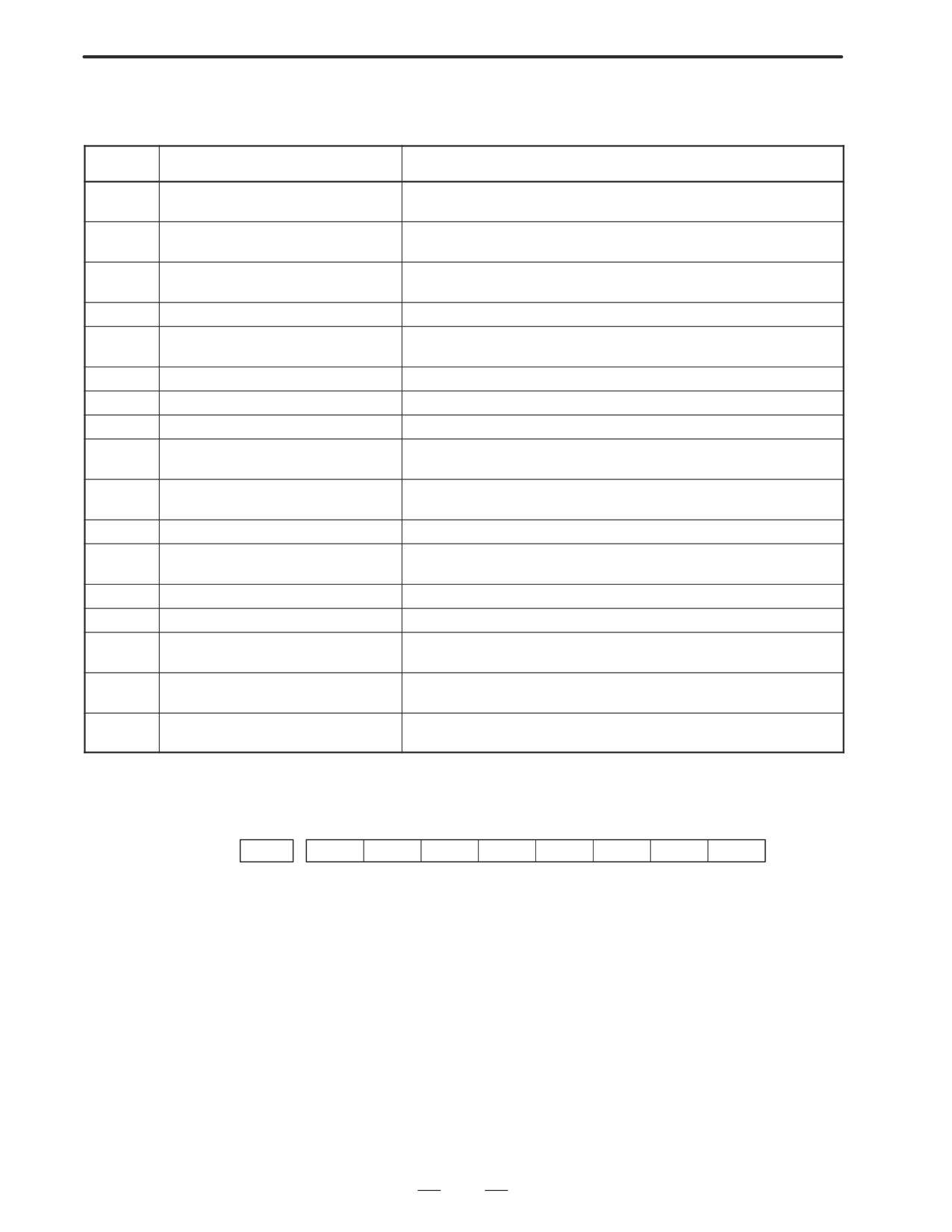
???
BP/S alarm
BP/S alarm occurs in the same number as the P/S alarm that occurs in
ordinary program edit. (070, 071, 072, 073, 074 085,086,087 etc.)
140
BP/S alarm
It was attempted to select or delete in the background a program being
selected in the foreground. (Note)
Use background editing correctly.
NOTE
Alarm in background edit is displayed in the key input line of the background edit screen instead
of the ordinary alarm screen and is resettable by any of the MDI key operation.
(4) Absolute pulse coder (APC) alarm
Number
Message
Contents
300
nth-axis origin return
Manual reference position return is required for the nth-axis (n=1 - 8).
301
APC alarm: nth-axis communication
nth-axis (n=1 - 8) APC communication error. Failure in data transmis-
sion
Possible causes include a faulty APC, cable, or servo interface module.
302
APC alarm: nth-axis over time
nth-axis (n=1 - 8) APC overtime error.
Failure in data transmission.
Possible causes include a faulty APC, cable, or servo interface module.
303
APC alarm: nth-axis framing
nth-axis (n=1 - 8) APC framing error. Failure in data transmission.
Possible causes include a faulty APC, cable, or servo interface module.
304
APC alarm: nth-axis parity
nth-axis (n=1 - 8) APC parity error.
Failure in data transmission.
Possible causes include a faulty APC, cable, or servo interface module.
305
APC alarm: nth-axis pulse error
nth-axis (n=1 - 8) APC pulse error alarm.
APC alarm.APC or cable may be faulty.
306
APC alarm: nth-axis battery
nth-axis (n=1 - 8) APC battery voltage has decreased to a low level so
voltage 0
that the data cannot be held.
APC alarm. Battery or cable may be faulty.
307
APC alarm: nth-axis battery low 1
nth-axis (n=1 - 8) axis APC battery voltage reaches a level where the
battery must be renewed.
APC alarm. Replace the battery.
308
APC alarm: nth-axis battery low 2
nth-axis (n=1 - 8) APC battery voltage has reached a level where the
battery must be renewed (including when power is OFF).
APC alarm .Replace battery.
309
APC ALARM:
Return to the origin has been attempted without first rotating the motor
n AXIS ZRN IMPOSSIBL
one or more times. Before returning to the origin, rotate the motor one
or more times then turn off the power.
383
A. ALARM LIST
APPENDIX
B-63005EN/01
(5) Serial pulse coder
(SPC) alarms
No.
Message
Description
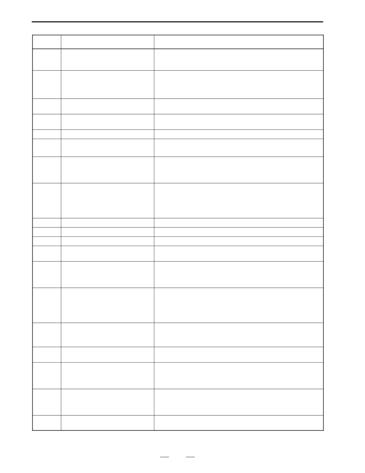
360
n AXIS : ABNORMAL CHECKSUM
A checksum error occurred in the built-in pulse coder.
(INT)
361
n AXIS : ABNORMAL PHASE DATA
A phase data error occurred in the built-in pulse coder.
(INT)
362
n AXIS : ABNORMAL REV.DATA
A rotation speed count error occurred in the built-in pulse coder.
(INT)
363
n AXIS : ABNORMAL CLOCK (INT)
A clock error occurred in the built-in pulse coder.
364
n AXIS : SOFT PHASE ALARM (INT)
The digital servo software detected invalid data in the built-in pulse
coder.
365
n AXIS : BROKEN LED (INT)
An LED error occurred in the built-in pulse coder.
366
n AXIS : PULSE MISS (INT)
A pulse error occurred in the built-in pulse coder.
367
n AXIS : COUNT MISS (INT)
A count error occurred in the built-in pulse coder.
368
n AXIS : SERIAL DATA ERROR
Communication data from the built-in pulse coder cannot be re-
(INT)
ceived.
369
n AXIS : DATA TRANS. ERROR
A CRC or stop bit error occurred in the communication data being
(INT)
received from the built-in pulse coder.
380
n AXIS : BROKEN LED (EXT)
The separate detector is erroneous.
381
n AXIS : ABNORMAL PHASE
A phase data error occurred in the separate linear scale.
(EXT LIN)
382
n AXIS : COUNT MISS (EXT)
A pulse error occurred in the separate detector.
383
n AXIS : PULSE MISS (EXT)
A count error occurred in the separate detector.
384
n AXIS : SOFT PHASE ALARM
The digital servo software detected invalid data in the separate de-
(EXT)
tector.
385
n AXIS : SERIAL DATA ERROR
Communication data from the separate detector cannot be received.
(EXT)
386
n AXIS : DATA TRANS. ERROR
A CRC or stop bit error occurred in the communication data being
(EXT)
received from the separate detector.
D The details of serial
pulse coder alarm
#7
#6
#5
#4
#3
#2
#1
#0
202
CSA
BLA
PHA
PCA
BZA
CKA
SPH
#6 (CSA) : Check sum alarm has occurred.
#5 (BLA) : Battery low alarm has occurred.
#4 (PHA) : Phase data trouble alarm has occurred.
#3 (PCA) : Speed count trouble alarm has occurred.
#2 (BZA) : Battery zero alarm has occurred.
#1 (CKA) : Clock alarm has occurred.
#0 (SPH) : Soft phase data trouble alarm has occurred.
384

B-63005EN/01
APPENDIX
A. ALARM LIST
#7
#6
#5
#4
#3
#2
#1
#0
203
DTE
CRC
STB
PRM
#7 (DTE) : Data error has occurred.
#6 (CRC) : CRC error has occurred.
#5 (STB) : Stop bit error has occurred.
#4 (PRM) : Parameter error alarm has occurred. In this case, a servo parameter error
alarm (No. 417) is also output.
(6) Servo alarms
Number
Message
Contents
401
SERVO ALARM: n-TH AXIS VRDY
The n-th axis (axis 1-8) servo amplifier READY signal (DRDY) went off.
OFF
Refer to procedure of trouble shooting.
404
SERVO ALARM: n-TH AXIS VRDY
Even though the n-th axis (axis 1-8) READY signal (MCON) went off,
ON
the servo amplifier READY signal (DRDY) is still on. Or, when the power
was turned on, DRDY went on even though MCON was off.
Check that the servo interface module and servo amp are connected.
405
SERVO ALARM: (ZERO POINT RE-
Position control system fault. Due to an NC or servo system fault in the
TURN FAULT)
reference position return, there is the possibility that reference position
return could not be executed correctly. Try again from the manual refer-
ence position return.
407
SERVO ALARM: EXCESS ERROR
The difference in synchronous axis position deviation exceeded the set
value.
409
SERVO ALARM: n AXIS TORQUE
Abnormal servo motor load has been detected. Alternatively, abnormal
ALM
spindle motor load has been detected in Cs mode.
410
SERVO ALARM: n-TH AXIS - EX-
The position deviation value when the n-th axis (axis 1-8) stops is larg-
CESS ERROR
er than the set value.
Refer to procedure of trouble shooting.
411
SERVO ALARM: n-TH AXIS - EX-
The position deviation value when the n-th axis (axis 1-8) moves is
CESS ERROR
larger than the set value.
Refer to procedure of trouble shooting.
413
SERVO ALARM: n-th AXIS - LSI
The contents of the error register for the n-th axis (axis 1-8) exceeded
OVERFLOW
"231 power. This error usually occurs as the result of an improperly set
parameters.
415
SERVO ALARM: n-TH AXIS - EX-
A speed higher than 511875 units/s was attempted to be set in the n-th
CESS SHIFT
axis (axis 1-8). This error occurs as the result of improperly set CMR.
417
SERVO ALARM: n-TH AXIS - PA-
This alarm occurs when the n-th axis (axis 1-8) is in one of the condi-
RAMETER INCORRECT
tions listed below.
(Digital servo system alarm)
1) The value set in Parameter No. 2020 (motor form) is out of the speci-
fied limit.
2) A proper value (111 or -111) is not set in parameter No.2022 (motor
revolution direction).
3) Illegal data (a value below 0, etc.) was set in parameter No. 2023
(number of speed feedback pulses per motor revolution).
4) Illegal data (a value below 0, etc.) was set in parameter No. 2024
(number of position feedback pulses per motor revolution).
5) Parameters No. 2084 and No. 2085 (flexible field gear rate) have not
been set.
6) A value outside the limit of {1 to the number of control axes} or a non-
continuous value (Parameter 1023 (servo axis number) contains a
value out of the range from 1 to the number of axes, or an isolated
value (for example, 4 not prceded by 3).was set in parameter No.
1023 (servo axisnumber).
385
A. ALARM LIST
APPENDIX
B-63005EN/01
Number
Message
Contents
420
SERVO ALARM: n AXIS SYNC
During simple synchronous control, the difference between the torque
TORQUE
commands for the master and slave axes exceeded the value set in pa-
(M series)
rameter No. 2031.
421
SERVO ALARM: n AXIS EXCESS
The difference between the errors in the semi-closed loop and closed
ER (D)
loop has become excessive during dual position feedback. Check the
values of the dual position conversion coefficients in parameters No.
2078 and 2079.
422
SERVO ALARM: n AXIS
In torque control of PMC axis control, a specified allowable speed
has been exceeded.
423
SERVO ALARM: n AXIS
In torque control of PMC axis control, the parameter-set allowable
cumulative travel distance has been exceeded.
430
n AXIS : SV. MOTOR OVERHEAT
A servo motor overheat occurred.
431
n AXIS : CNV. OVERLOAD
1) PSM: Overheat occurred.
2) β series SVU: Overheat occurred.
432
n AXIS : CNV. LOWVOLT CON./
1) PSM: Phase missing occurred in the input voltage.
POWFAULT
2) PSMR: The control power supply voltage has dropped.
3) α series SVU: The control power supply voltage has dropped.
433
n AXIS : CNV. LOW VOLT DC LINK
1) PSM: The DC link voltage has dropped.
2) PSMR: The DC link voltage has dropped.
3) α series SVU: The DC link voltage has dropped.
4) β series SVU: The DC link voltage has dropped.
434
n AXIS : INV. LOW VOLT CONTROL
SVM: The control power supply voltage has dropped.
435
n AXIS : INV. LOW VOLT DC LINK
SVM: The DC link voltage has dropped.
436
n AXIS : SOFTTHERMAL (OVC)
The digital servo software detected the soft thermal state (OVC).
437
n AXIS : CNV. OVERCURRENT
PSM: Overcurrent flowed into the input circuit.
POWER
438
n AXIS : INV. ABNORMAL CUR-
1) SVM: The motor current is too high.
RENT
2) α series SVU: The motor current is too high.
3) β series SVU: The motor current is too high.
439
n AXIS : CNV. OVERVOLT POWER
1) PSM: The DC link voltage is too high.
2) PSMR: The DC link voltage is too high.
3) α series SVU: The C link voltage is too high.
4) β series SVU: The link voltage is too high.
440
n AXIS : CNV. EX DECELERATION
1) PSMR: The regenerative discharge amount is too large.
POW.
2) α series SVU: The regenerative discharge amount is too large. Al-
ternatively, the regenerative discharge circuit is abnormal.
441
n AXIS : ABNORMAL CURRENT
The digital servo software detected an abnormality in the motor cur-
OFFSET
rent detection circuit.
442
n AXIS : CNV. CHARGE FAULT/INV.
1) PSM: The spare discharge circuit of the DC link is abnormal.
DB
2) PSMR: The spare discharge circuit of the DC link is abnormal.
3) α series SVU: The dynamic brake circuit is abnormal.
443
n AXIS : CNV. COOLING FAN FAIL-
1) PSM: The internal stirring fan failed.
URE
2) PSMR: The internal stirring fan failed.
3) β series SVU: The internal stirring fan failed.
444
n AXIS : INV. COOLING FAN FAIL-
SVM: The internal stirring fan failed.
URE
386
B-63005EN/01
APPENDIX
A. ALARM LIST
Number
Message
Contents
445
n AXIS : SOFT DISCONNECT
The digital servo software detected a broken wire in the pulse coder.
ALARM
446
n AXIS : HARD DISCONNECT
A broken wire in the built-in pulse coder was detected by hardware.
ALARM
447
n AXIS : HARD DISCONNECT (EXT)
A broken wire in the separate detector was detected by hardware.
448
n AXIS : UNMATCHED FEEDBACK
The sign of feedback data from the built-in pulse coder differs from
ALARM
that of feedback data from the separate detector.
449
n AXIS : INV. IPM ALARM
1) SVM: IPM (intelligent power module) detected an alarm.
2) α series SVU: IPM (intelligent power module) detected an alarm.
460
n AXIS : FSSB DISCONNECT
FSSB communication was disconnected suddenly. The possible
causes are as follows:
1) The FSSB communication cable was disconnected or broken.
2) The power to the amplifier was turned off suddenly.
3) A low-voltage alarm was issued by the amplifier.
461
n AXIS : ILLEGAL AMP INTERFACE
The axes of the 2-axis amplifier were assigned to the fast type inter-
face.
462
n AXIS : SEND CNC DATA FAILED
Because of an FSSB communication error, a slave could not receive
correct data.
463
n AXIS : SEND SLAVE DATA
Because of an FSSB communication error, the servo system could
FAILED
not receive correct data.
464
n AXIS : WRITE ID DATA FAILED
An attempt was made to write maintenance information on the ampli-
fier maintenance screen, but it failed.
465
n AXIS : READ ID DATA FAILED
At power-up, amplifier initial ID information could not be read.
466
n AXIS : MOTOR/AMP COMBINA-
The maximum current rating for the amplifier does not match that for
TION
the motor.
467
n AXIS : ILLEGAL SETTING OF
The servo function for the following has not been enabled when an
AXIS
axis occupying a single DSP (corresponding to two ordinary axes) is
specified on the axis setting screen.
1. Learning control (bit 5 of parameter No. 2008 = 1)
2. High-speed current loop (bit 0 of parameter No. 2004 = 1)
3. High-speed interface axis (bit 4 of parameter No. 2005 = 1)
D Details of servo alarm
The details of servo alarm are displayed in the diagnosis display (No. 200
and No.204) as shown below.
#7
#6
#5
#4
#3
#2
#1
#0
200
OVL
LV
OVC
HCA
HVA
DCA
FBA
OFA
#7 (OVL) : An overload alarm is being generated.
#6 (LV) : A low voltage alarm is being generated in servo amp.
#5 (OVC) : A overcurrent alarm is being generated inside of digital servo.
#4 (HCA) : An abnormal current alarm is being generated in servo amp.
#3 (HVA) : An overvoltage alarm is being generated in servo amp.
#2 (DCA) : A regenerative discharge circuit alarm is being generated in servo amp.
#1 (FBA) : A disconnection alarm is being generated.
#0 (OFA) : An overflow alarm is being generated inside of digital servo.
387
A. ALARM LIST
APPENDIX
B-63005EN/01
#7
#6
#5
#4
#3
#2
#1
#0
201
ALD
EXP
When OVL equal 1 in diagnostic data No.200 (servo alarm No. 400 is
being generated):
#7 (ALD)
0 : Motor overheating
1 : Amplifier overheating
When FBAL equal 1 in diagnostic data No.200 (servo alarm No. 416 is
being generated):
ALD
EXP
Alarm details
1
0
Built-in pulse coder disconnection (hardware)
1
1
Separately installed pulse coder disconnection
(hardware)
0
0
Pulse coder is not connected due to software.
#7
#6
#5
#4
#3
#2
#1
#0
204
OFS
MCC
LDA
PMS
#6 (OFS)
:
A current conversion error has occured in the digital servo.
#5 (MCC) : A magnetic contactor contact in the servo amplifier has welded.
#4 (LDA) : The LED indicates that serial pulse coder C is defective
#3 (PMS) : A feedback pulse error has occured because the feedback cable is
defective.
(7) Over travel alarms
Number
Message
Contents
500
OVER TRAVEL : +n
Exceeded the n-th axis (axis 1-8) + side stored stroke limit I.
(Parameter No.1320 or 1326 NOTE)
501
OVER TRAVEL : -n
Exceeded the n-th axis (axis 1-8) - side stored stroke limit I.
(Parameter No.1321 or 1327 NOTE)
502
OVER TRAVEL : +n
Exceeded the n-th axis (axis 1-8) + side stored stroke limit II.
(Parameter No.1322 )
503
OVER TRAVEL : -n
Exceeded the n-th axis (axis 1-8) - side stored stroke limit II.
(Parameter No.1323)
504
OVER TRAVEL : +n
Exceeded the n-th axis (axis 1-8) + side stored stroke limit III.
(Parameter No.1324 )
505
OVER TRAVEL : -n
Exceeded the n-th axis (axis 1-8) - side stored stroke limit III.
(Parameter No.1325 )
506
OVER TRAVEL : +n
Exceeded the n-th axis (axis 1-8) + side hardware OT.
507
OVER TRAVEL : -n
Exceeded the n-th axis (axis 1-8) - side hardware OT.
508
INTERFERENCE: +n
A tool moving in the positive direction along the n axis has fouled anoth-
(T series (two-path control))
er tool post.
509
INTERFERENCE: -n
A tool moving in the negative direction along the n axis has fouled anoth-
(T series (two-path control))
er tool post.
388
B-63005EN/01
APPENDIX
A. ALARM LIST
Number
Message
Contents
510
OVER TRAVEL: +n
Alarm for stroke check prior to movement. The end point specified in a
block falls within the forbidden area defined with the stroke limit in the
positive direction along the N axis. Correct the program.
511
OVER TRAVEL: -n
Alarm for stroke check prior to movement. The end point specified in a
block falls within the forbidden area defined with the stroke limit in the
negative direction along the N axis. Correct the program.
NOTE
Parameters 1326 and 1327 are effective when EXLM(stroke limit switch signal) is on.
(8) Overheat alarms
Number
Message
Contents
700
OVERHEAT: CONTROL UNIT
Control unit overheat
Check that the fan motor operates normally, and clean the air filter.
701
OVERHEAT: FAN MOTOR
The fan motor on the top of the cabinet for the contorl unit is overheated.
Check the operation of the fan motor and replace the motor if necessary.
704
OVERHEAT: SPINDLE
Spindle overheat in the spindle fluctuation detection
(1) If the cutting load is heavy, relieve the cutting condition.
(2) Check whether the cutting tool is share.
(3) Another possible cause is a faulty spindle amp.
(9) Rigid tapping alarms
Number
Message
Contents
740
RIGID TAP ALARM: EXCESS ER-
The positional deviation of the stopped spindle has exceeded the set
ROR
value during rigid tapping.
741
RIGID TAP ALARM: EXCESS ER-
The positional deviation of the moving spindle has exceeded the set val-
ROR
ue during rigid tapping.
742
RIGID TAP ALARM: LSI OVER-
An LSI overflow has occurred for the spindle during rigid tapping.
FLOW
389
A. ALARM LIST
APPENDIX
B-63005EN/01
(10)Serial spindle alarms
Number
Message
Contents
749
S-SPINDLE LSI ERROR
It is serial communication error while system is executing after power
supply on. Following reasons can be considered.
1) Optical cable connection is fault or cable is not connected or cable
is cut.
2) MAIN CPU board or option 2 board is fault.
3) Spindle amp. printed board is fault.
If this alarm occurs when CNC power supply is turned on or when
this alarm can not be cleared even if CNC is reset, turn off the power
supply also turn off the power supply in spindle side.
750
SPINDLE SERIAL LINK START
This alarm is generated when the spindle control unit is not ready for
FAULT
starting correctly when the power is turned on in the system with the
serial spindle.
The four reasons can be considered as follows:
1) An improperly connected optic cable, or the spindle control unit’s
power is OFF.
2) When the NC power was turned on under alarm conditions other
than SU-01 or AL-24 which are shown on the LED display of the
spindle control unit.
In this case, turn the spindle amplifier power off once and perform
startup again.
3) Other reasons (improper combination of hardware)
This alarm does not occur after the system including the spindle con-
trol unit is activated.
4) The second spindle (when SP2, bit 4 of parameter No. 3701, is 1)
is in one of the above conditions 1) to 3).
See diagnostic display No. 409 for details.
751
FIRST SPINDLE ALARM
This alarm indicates in the NC that an alarm is generated in the spindle
DETECTION (AL-XX)
unit of the system with the serial spindle. The alarm is displayed in form
AL-XX (XX is a number). Refer to B.3 or B.4 Alarms displayed on
spindle servo unit .The alarm number XX is the number indicated on
the spindle amplifier. The CNC holds this number and displays on the
screen.
752
FIRST SPINDLE MODE CHANGE
This alarm is generated if the system does not properly terminate a
FAULT
mode change. The modes include the Cs contouring, spindle position-
ing, rigid tapping, and spindle control modes. The alarm is activated if
the spindle control unit does not respond correctly to the mode change
command issued by the NC.
754
SPINDLE-1 ABNORMAL TORQUE
Abnormal first spindle motor load has been detected.
ALM
761
SECOND SPINDLE ALARM
Refer to alarm No. 751. (For 2nd axis)
DETECTION (AL-XX)
762
SECOND SPINDLE MODE
Refer to alarm No. 752.(For 2nd axis)
CHANGE FAULT
764
SPINDLE-2 ABNORMAL TORQUE
Same as alarm No. 754 (for the second spindle)
ALM
771
SPINDLE-3 ALARM DETECT
Same as alarm No. 751 (for the third spindle)
(AL-XX)
772
SPINDLE-3 MODE CHANGE EROR
Same as alarm No. 752 (for the third spindle)
774
SPINDLE-3 ABNORMAL TORQUE
Same as alarm No. 754 (for the third spindle)
ALM
390
B-63005EN/01
APPENDIX
A. ALARM LIST
D The details of spindle
The details of spindle alarm No. 750 are displayed in the diagnosis display
alarm No.750
(No. 409) as shown below.
#7
#6
#5
#4
#3
#2
#1
#0
409
SPE
S2E
S1E
SHE
#3 (SPE)
0 : In the spindle serial control, the serial spindle parameters fulfill the
spindle unit startup conditions.
1 : In the spindle serial control, the serial spindle parameters do not fulfill
the spindle unit startup conditions.
#2 (S2E)
0 : The second spindle is normal during the spindle serial control startup.
1 : The second spindle was detected to have a fault during the spindle
serial control startup.
#1 (S1E)
0 : The first spindle is normal during the spindle serial control startup.
1 : The first spindle was detected to have a fault during the spindle axis
serial control startup.
#0 (SHE)
0 : The serial communications module in the CNC is normal.
1 : The serial communications module in the CNC was detected to have a
fault.
(11)Safety zone alarms
Number
Message
Contents
4800
ZONE : PUNCHING INHIBITED 1
When a safety zone check was executed, a punch command was
specified in area 1 where punching is inhibited.
4801
ZONE : PUNCHING INHIBITED 2
When a safety zone check was executed, a punch command was
specified in area 2 where punching is inhibited.
4802
ZONE : PUNCHING INHIBITED 3
When a safety zone check was executed, a punch command was
specified in area 3 where punching is inhibited.
4803
ZONE : PUNCHING INHIBITED 4
When a safety zone check was executed, a punch command was
specified in area 4 where punching is inhibited.
4810
ZONE : ENTERING INHIBITED 1 +X
When a safety zone check was executed, the machine moving in the
positive X direction entered area 1 into which entry is inhibited.
4811
ZONE : ENTERING INHIBITED 1
When a safety zone check was executed, the machine moving in the
–X
negative X direction entered area 1 into which entry is inhibited.
4812
ZONE : ENTERING INHIBITED 2 +X
When a safety zone check was executed, the machine moving in the
positive X direction entered area 2 into which entry is inhibited.
4813
ZONE : ENTERING INHIBITED 2
When a safety zone check was executed, the machine moving in the
–X
negative X direction entered area 2 into which entry is inhibited.
4814
ZONE : ENTERING INHIBITED 3 +X
When a safety zone check was executed, the machine moving in the
positive X direction entered area 3 into which entry is inhibited.
4815
ZONE : ENTERING INHIBITED 3
When a safety zone check was executed, the machine moving in the
–X
negative X direction entered area 3 into which entry is inhibited.
4816
ZONE : ENTERING INHIBITED 4 +X
When a safety zone check was executed, the machine moving in the
positive X direction entered area 4 into which entry is inhibited.
4817
ZONE : ENTERING INHIBITED 4
When a safety zone check was executed, the machine moving in the
–X
negative X direction entered area 4 into which entry is inhibited.
4830
ZONE : ENTERING INHIBITED 1 +Y
When a safety zone check was executed, the machine moving in the
positive X direction entered area 1 into which entry is inhibited.
391
A. ALARM LIST
APPENDIX
B-63005EN/01
Number
Message
Contents
4831
ZONE : ENTERING INHIBITED 1
When a safety zone check was executed, the machine moving in the
–Y
negative Y direction entered area 1 into which entry is inhibited.
4832
ZONE : ENTERING INHIBITED 2 +Y
When a safety zone check was executed, the machine moving in the
positive Y direction entered area 2 into which entry is inhibited.
4833
ZONE : ENTERING INHIBITED 2
When a safety zone check was executed, the machine moving in the
–Y
negative Y direction entered area 2 into which entry is inhibited.
4834
ZONE : ENTERING INHIBITED 3 +Y
When a safety zone check was executed, the machine moving in the
positive Y direction entered area 3 into which entry is inhibited.
4835
ZONE : ENTERING INHIBITED 3
When a safety zone check was executed, the machine moving in the
–Y
negative Y direction entered area 3 into which entry is inhibited.
4836
ZONE : ENTERING INHIBITED 4 +Y
When a safety zone check was executed, the machine moving in the
positive Y direction entered area 4 into which entry is inhibited.
4837
ZONE : ENTERING INHIBITED 4
When a safety zone check was executed, the machine moving in the
–Y
negative Y direction entered area 4 into which entry is inhibited.
4870
AUTO SETTING FEED ERROR
The feed rate of safety zone auto setting is other than the parameter
value (No. 16538, No. 16539).
4871
AUTO SETTING PIECES ERROR
In safety zone auto setting, the safety zone pieces are not correct. Or
the position detector has gone wrong, please tell your machine tool
builder.
4872
AUTO SETTING COMMAND
M code, S code or T code is specified with safety zone auto setting
ERROR
command (G32).
G32 is specified in the nibbling mode, in the cutter compensation, in
the rotation mode or the scaling mode.
(12) System alarms
(These alarms cannot be reset with reset key.)
Number
Message
Description
900
ROM PARITY
A parity error occurred in the CNC, macro, or servo ROM. Correct
the contents of the flash ROM having the displayed number.
910
SRAM PARITY : (BYTE 0)
A RAM parity error occurred in the part program storage RAM. Clear
the RAM, or replace the SRAM module or motherboard. Subse-
911
SRAM PARITY : (BYTE 1)
quently, re-set the parameters and all other data.
912
DRAM PARITY : (BYTE 0)
A RAM parity error occurred in the DRAM module. Replace the
DRAM module
913
DRAM PARITY : (BYTE 1)
914
DRAM PARITY : (BYTE 2)
915
DRAM PARITY : (BYTE 3)
916
DRAM PARITY : (BYTE 4)
917
DRAM PARITY : (BYTE 5)
918
DRAM PARITY : (BYTE 6)
919
DRAM PARITY : (BYTE 7)
920
SERVO ALARM (1-4 AXIS)
Servo alarm (first to fourth axis). A watchdog alarm condition oc-
curred, or a RAM parity error occurred in the axis control card.
Replace the axis control card.
921
SERVO ALARM (5-8 AXIS)
Servo alarm (fifth to eighth axis). A watchdog alarm condition oc-
curred, or a RAM parity error occurred in the axis control card.
Replace the axis control card.
392
B-63005EN/01
APPENDIX
A. ALARM LIST
Number
Message
Description
926
FSSB ALARM
FSSB alarm.
Replace the axis control card.
930
CPU INTERRUPT
CPU error (abnormal interrupt).
The motherboard or CPU card may be faulty.
950
PMC SYSTEM ALARM
An error occurred in the PMC.
The PMC control circuit on the motherboard may be faulty.
951
PMC WATCH DOG ALARM
An error occurred in the PMC.
(Watchdog alarm)
The motherboard may be faulty.
972
NMI OCCURRED IN OTHER MOD-
An NMI occurred on a board other than the motherboard.
ULE
The option board may be faulty.
973
NON MASK INTERRUPT
An NMI occurred as a result of an unknown cause.
974
F-BUS ERROR
A bus error occurred on the FANUC bus.
The motherboard or option board may be faulty.
975
BUS ERROR
A bus error occurred on the motherboard.
The motherboard may be faulty.
976
L-BUS ERROR
A bus error occurred on the local bus.
The motherboard may be faulty.
393
A. ALARM LIST
APPENDIX
B-63005EN/01
A.2
LIST OF ALARMS
(PMC)
(1) Alarm messages (PMC)
Message
Contents and solution
ALARM NOTHING
Normal status
ER00 PROGRAM DATA
The sequence program in the ROM is not written correctly.
ERROR(ROM)
(solution)
Please exchange ROM for the sequence program.
ER01 PROGRAM DATA
The sequence program in the debugging RAM is defective.
ERROR(RAM)
(solution)
Please clear the debugging RAM and input LADDER again.
The debugging RAM is not installed though the RAM is selected.
(solution)
Please install the debugging RAM or install ROM for sequence program
and select ROM with K17#3=0.
ER02 PROGRAM SIZE OVER
The size of sequence program exceeds the maximum size of LADDER(PMC-RC
only).
(solution)
Please change MAX LADDER AREA SIZE at the SYSPRM screen and
restart the system.
ER03 PROGRAM SIZE
The size of sequence program exceeds the option specification size.
ERROR(OPTION)
(solution)
Please increase the option specification size.
Or, reduce the size of sequence program.
ER04 PMC TYPE UNMATCH
The PMC model setting of the sequence program is not corresponding to an actual
model.
(solution)
Please change the PMC model setting by the offline programmer.
ER05 PMC MODULE TYPE
The module type of the PMC engine is not correct.
ERROR
(solution)
Please exchange the module of PMC engine for a correct one.
ER07 NO OPTION
There is no step number option of LADDER.
(LADDER STEP)
ER10 OPTION AREA NOTHING
The management software for the PMC-RB has not been transferred.
(series name)
(solution)
The software installation is not consistent with the order. Contact FANUC.
ER11 OPTION AREA NOTHING
The management software for the PMC C board has not been transferred.
(series name)
(solution)
The software installation is not consistent with the order. Contact FANUC.
ER12 OPTION AREA ERROR
The series of the management software for the PMC-RB differs between BASIC and
(series name)
OPTION.
(solution)
Contact FANUC.
ER13 OPTION AREA ERROR
The series of the management software for the PMC C board differs between BASIC
(series name)
and OPTION.
(solution)
Contact FANUC.
ER14 OPTION AREA VERSIION
The edition of the management software for the PMC-RB differs between BASIC
ERROR (series name)
and OPTION.
(solution)
Contact FANUC.
ER15 OPTION AREA VERSIION
The edition of the management software for the PMC C board differs between BASIC
ERROR (series name)
and OPTION.
(solution)
Contact FANUC.
ER 16 RAM CHECK ERROR
The debugging RAM cannot be read/written normally.
(PROGRAM RAM)
(solution)
Please exchange the debugging RAM.
394
B-63005EN/01
APPENDIX
A. ALARM LIST
Message
Contents and solution
ER17 PROGRAM PARITY
The parity error occurred on ROM for sequence program or the debugging RAM.
(solution)
ROM: The deterioration of ROM may be deteriorated
Please exchange ROM for the sequence program
RAM: Please edit the sequence program once on PMC
Still the error occurs, exchange the debugging RAM.
ER18 PROGRAM DATA ERROR
Transferring the sequence program from offline programmer was interrupted by the
BY I/O
power off etc.
(solution)
Please clear the sequence program and transfer the sequence program
again.
ER19 LADDER DATA ERROR
Editing the LADDER was interrupted by the power off or by the switch to the CNC
screen by the function key etc.
(solution)
Please edit LADDER once on PMC.
Or, please input LADDER again.
ER20 SYMBOL/COMMENT
Editing the symbol and comment was interrupted by the power off or by the switch to
DATA ERROR
the CNC screen by the function key etc.
(solution)
Please edit symbol and comment once on PMC.
Or, please input symbol and comment again.
ER21 MESSAGE DATA ERROR
Editing the message data was interrupted by the power off or the switch to the CNC
screen by the function key etc.
(solution)
Please edit message data once on PMC.
Or, please input message data again.
ER22 PROGRAM NOTHING
There is no sequence program
ER23 PLEASE TURN OFF POW-
There is a change in setting LADDER MAX AREA SIZE etc.
ER
(solution)
Please restart the system to make the change effective.
ER24 LADDER, LANGUAGE
The C program area overlaps the ladder program area.
AREA OVERLAP
(solution)
Adjust the address range assigned to C programs.
ER25 SOFTWARE VERSION
The PMC-RB management software editions are inconsistent.
ERROR (PMCAOPT)
(solution)
Contact FANUC.
ER26 SOFTWARE VERSION
The PMC-RB management software cannot be initialized.
ERROR (PMCAOPT)
(solution)
Contact FANUC.
ER32 NO I/O DEVICE
Any DI/DO unit of I/O Unit or the connection unit etc. is not connected. When built-in
I/O card is connected, this message is not displayed.
(solution)
When built-in I/O card is used:
Please confirm whether the built-in I/O card is certainly connected with.
When I/O Link is used:
Please confirm whether the DI/DO units turning on. Or please confirm
the connection of the cable.
ER33 SLC ERROR
The LSI for I/O Link is defective.
(solution)
Please exchange the module of PMC engine.
ER34 SLC ERROR(xx)
The communication with the DI/DO units of the xx group failed.
(solution)
Please confirm the connection of the cable connected to the DI/DO
units of the xx group.
Please confirm whether the DI/DO units turned on earlier than CNC and
PMC. Or, please exchange the module of PMC engine on the DI/DO
units of the xx group
395
A. ALARM LIST
APPENDIX
B-63005EN/01
Message
Contents and solution
ER35 TOO MUCH OUTPUT
The number of the output data in the xx group exceeded the max. The data, which
DATA IN GROUP(xx)
exceed 32 bytes, become ineffective.
(solution)
Please refer to the following for the number of the data for each group.
“FANUC I/O Unit-MODEL A connecting and maintenance manual”
(B-61813E)
“FANUC I/O Unit-MODEL B connecting manual”(B-62163E)
ER36 TOO MUCH INPUT DATA
The number of the input data in the xx group exceeded the max. The data, which
IN GROUP(xx)
exceed 32 bytes, become ineffective.
(solution)
Please refer to the following for the number of the data for each group.
“FANUC I/O Unit-MODEL A connecting and maintenance manual”
(B-61813E)
“FANUC I/O Unit-MODEL B connecting manual”(B-62163E)
ER38 MAX SETTING OUTPUT
The assignment data for a group exceeds 128 bytes.
DATA OVER(xx)
(The assignment data of output side of xx group or later become ineffective.)
(solution)
Please reduce the assignment data to 128 bytes or less for the number
of
the output data of each group.
ER39 MAX SETTING INPUT
The assignment data for a group exceeds 128 bytes.
DATA OVER(xx)
(The assignment data of input side of xx group or later become infective.)
(Solution) Please reduce the assignment data to 128 bytes or less for the number
of
the input data of each goup.
WN01 LADDER MAX SIZE
The MAX LADDER AREA SIZE in the system parameter is illegal.
ERROR
(solution)
Set the correct value to MAX LADDER AREA SIZE and restart the sys-
tem.
*When ER00 to ER26 occur, sequence program is not available.
Message
Contents and solution
WN02 OPERATE PANEL
The address setting data of the operator’s panel for FS-0 is illegal.
ADDRESS ERROR
(solution)
Please correct the address setting data.
WN03 ABORT NC-WINDOW/
LADDER was stopped while CNC and PMC were communicating.
EXIN
The functional instruction WINDR, WINDW, EXIN, DISPB, and etc. may not work nor-
mally.
(solution)
When restarting the system, this alarm will be released. Execute the
sequence program(Press RUN key) after confirming whether there is a
problem in LADDER or not.
WN04 UNAVAIL EDIT MODULE
The LADDER editing module cannot be recognized.(PMC-RAx/RBxx=1 to 3)
(solution)
Please confirm the slot position installed.
Please confirm the installed module.
WN05 PMC TYPE NO CONVER-
A ladder program for the PMC-RA3/RA5 was transferred to the PMC-RB5.
SION
(solution)
Correct the ladder type.
WN06 TASK STOPPED BY DE-
Some user tasks are stopped by break point of the debugging function.
BUG FUNC
WN07 LADDER SP ERROR
When functional instruction CALL(SUB65) or CALLU(SUB66) was executed, the stack
(STACK)
of the LADDER overflowed.
(solution)
Please reduce the nesting of the subprogram to 8 or less.
WN17 NO OPTION (LANGUAGE)
There is no C language option.
WN18 ORIGIN ADDRESS
The LANGUAGE ORIGIN address of the system parameter is wrong
ERROR
(solution)
Please set the address of symbol RC_CTLB_INIT in the map file to the
LANGUAGE ORIGIN of the system parameter.
396
B-63005EN/01
APPENDIX
A. ALARM LIST
Message
Contents and solution
WN19 GDT ERROR
The value of BASE, LIMIT or ENTRY of user defined GDT is illegal.
(BASE,LIMIT)
(solution)
Please correct the address in link control statement and build file.
WN20 COMMON MEM. COUNT
The number of common memories exceeds 8.
OVER
(solution)
Please reduce the number of common memories to 8 or less. It is
necessary to correct a link control statement,build file and the source file
for the common memory.
WN21 COMMON MEM. ENTRY
GDT ENTRY of the common memory is out of range.
ERROR
(solution)
Please correct the address of GDT ENTRY of the common memory in the
link control statement.
WN22 LADDER 3 PRIORITY
The priority of LADDER LEVEL 3 is out of range.
ERROR
(solution)
Please correct the value of LADDER LEVEL 3 in the link control statement
within the range of 0 or 10-99 or -1.
WN23 TASK COUNT OVER
The number of user tasks exceeds 16.
(solution)
Please confirm TASK COUNT in the link control statement. When the
number of tasks is changed, it is necessary to correct the link control
statement, build file and the composition of the files to be linked.
WN24 TASK ENTRY ADDR
The selector of the entry address to the user task is out of range.
ERROR
(solution)
Please correct the table of GDT in build file to the value within
32(20H)-95(5FH).
WN25 DATA SEG ENTRY
The entry address of the data segment is out of range.
ERROR
(solution)
Please correct DATA SEGMENT GDT ENTRY in the link control statement
and the table of GDT in build file within 32(20H)-95(5FH).
WN26 USER TASK PRIORITY
The priority of the user task is out of range.
ERROR
(solution)
Please correct the TASK LEVEL in link control statement within the
range of 10-99 or -1.
Note: Only one task can have TASK LEVEL -1 (including LADDER
LEVEL 3).
WN27 CODE SEG TYPE ERROR
The code segment type is illegal. The code segment of RENAMESEG in the binding
control file is wrong.
(solution)
Please correct the entry of the code segment in the link control statement
to correspond to the entry in the build file.
WN28 DATA SEG TYPE ERROR
The data segment type is illegal. The data segment of RENAMESEG in the binding con-
trol file is wrong.
(solution)
Please correct the entry of the code segment in the link control statement
to correspond to the entry in the build file.
WN29 COMMON MEM SEG
The segment type of common memory is illegal. The segment of RENAMESEG in the
TYPE ERROR
building control file of the common memory is wrong.
(solution)
Please correct the entry of common memory in the link control statement
to correspond to the entry in the build file.
WN30 IMPOSSIBLE ALLOCATE
The memories for the data and stack etc. cannot be allocated.
MEM.
(solution)
Please confirm whether the value of code segment in build file and USER
GDT ADDRESS in link control statement is correct or not.
Or please reduce the value of MAX LADDER AREA SIZE of the system
parameter and the size of the stack in link control statement at the least
WN31 IMPOSSIBLE EXECUTE
The library function cannot be executed.
LIBRARY
(solution)
Please confirm the object model of the library.
Or, system ROM of PMC must be replaced with one of later version.
397
A. ALARM LIST
APPENDIX
B-63005EN/01
Message
Contents and solution
WN32 LNK CONTROL DATA ER-
Link control statement data is illegal.
ROR
(solution)
Please confirm whether the address of symbol RC_ CTLB_INIT in map file
is set to LANGUAGE ORIGIN of the system parameter. Or, please make
the link control statement again.
WN33 LNK CONTROL VER. ER-
A link control statement data version error occurred.
ROR
(Solution) Correct the link control statement in the C program.
WN34 LOAD MODULE COUNT
The number of independent load modules exceeds eight.
OVER
(solution)
Decrease the number of independent load modules to eight or small
er.
WN35 CODE AREA OUT OF
The specified code area is beyond the address range.
RANGE
(solution)
Correct the C program.
WN36 LANGUAGE SIZE ERROR
The size of a C program exceeds the option size.
(OPTION)
(solution)
Decrease the size of the C program.
WN37 PROGRAM DATA ERROR
A C program is destroyed.
(LANG.)
(solution)
Transfer the C program again.
WN38 RAM CHECK ERROR
A C program is destroyed.
(LANG.)
(solution)
Transfer the C program again.
WN39 PROGRAM PARITY
A parity mismatch occurred in a C program.
(LANG.)
(solution)
Transfer the C program again.
WN40 PROGRAM DATA ERROR
Transfer of a C program was interrupted by, for example, a power failure.
BY I/O (LANG.)
(solution)
Clear the C program, then transfer the C program again.
WN41 LANGUAGE TYPE
A C program type mismatch occurred.
UNMATCH
(solution) Correct the C program.
WN42 UNDEFINE LANGUAGE
No language origin address is set.
ORIGIN ADDRESS
(solution)
Set the language origin address.
NOTE
Alarms WN17 to WN42 indicate errors related to PMC user
C programs.
398

B-63005EN/01
APPENDIX
A. ALARM LIST
(2)
System alarm messages (PMC-RB)
Message
Contents and solution
1
PC004 CPU ERR
A CPU error occurred in the PMC.
xxxxxxxx:yyyyyyyy
xxxxxxxx and yyyyyyyy indicate internal error code.
PC006 CPU ERR
xxxxxxxx:yyyyyyyy
If this error occurs, the motherboard may be faulty.
PC009 CPU ERR
xxxxxxxx:yyyyyyyy
Replace the motherboard, then check whether the error recurs. If the error still
PC010 CPU ERR
occurs even after the replacement of the motherboard, report the conditions un-
xxxxxxxx:yyyyyyyy
der which the error occurred (system configuration, operation, time and frequen-
cy of error occurrences, etc.) to FANUC.
2
PC030 RAM PARITY
aa:bb
A RAM parity error occurred in the PMC.
aa and bb indicate internal error code.
If this error occurs, the motherboard may be faulty.
Solution)
Replace the motherboard, then check whether the error recurs. If the error still
occurs even after the replacement of the motherboard, report the conditions un-
der which the error occurred (system configuration, operation, time and frequen-
cy of error occurrences, etc.) and the indicated internal error code to FANUC.
3
PC050 NMI SLC
aa:bb
A communication error occurred in the I/O Link.
aa and bb indicate internal error code.
If this error occurs, the possible causes are as follows:
(1) Although the base expansion is assigned when the I/O Unit A is used, the
base is not connected.
(2) A cable is not connected securely.
(3) Cabling is faulty.
(4) I/O equipment (I/O unit, Power Mate, etc.) is faulty.
(5) The motherboard is faulty.
Solution)
(1) Check whether the I/O assignment data and the actual I/O equipment con-
nection match.
(2) Check whether the cables are connected correctly.
(3) According to ”FANUC I/O Unit-MODEL A Connection and Maintenance
Manual” (B-61813E) or ”FANUC I/O Unit-MODEL B Connection manual”
(B-62163E), check for an error in the cable specifications.
(4) Replace the I/O unit interface module, cable, or motherboard. Then, check
whether the error still occurs.
4
PC060 FBUS
A bus error occurred in the PMC.
xxxxxxxx:yyyyyyyy
aa, xxxxxxxx, and yyyyyyyy indicate internal error code.
PC061 FL-R
xxxxxxxx:yyyyyyyy
If this error occurs, the hardware may be faulty.
PC062 FL-W
aa: xxxxxxxx:yyyyyyyy
Solution)
Report the conditions under which the error occurred (system configuration, op-
eration, time and frequency of error occurrences, tc.), the indicated internal error
code, and the LED status on each board to FANUC.
399

A. ALARM LIST
APPENDIX
B-63005EN/01
Message
Contents and solution
5
PC070 SUB65 CALL (STACK)
A stack error occurred during execution of ladder function instruction
CALL/CALLU.
Solution)
Check the correspondence between the CALL/CALLU instruction and SPE
instruction. If the error cannot be located, report the conditions under which the
error occurred and the ladder program to FANUC.
6
PC080 SYS EMG
A system alarm was caused by another software.
xxxxxxxx:yyyyyyyy
PC081 FL EMG
Solution)
xxxxxxxx:yyyyyyyy
Report the conditions under which the error occurred (system configuration, op-
eration, time and frequency of error occurrences, etc.), the indicated internal er-
ror code, and the LED status on each board to FANUC.
7
PC097 PARITY ERR
A parity error occurred in the PMC system.
(LADDER)
PC098 PARITY ERR (DRAM)
If this error occurred, the motherboard may be faulty.
Solution)
Replace the motherboard, then check whether the error recurs. If the error still
occurs even after the replacement of the motherboard, report the conditions un-
der which the error occurred (system configuration, operation, time and frequen-
cy of error occurrences, etc.) to FANUC.
(3)
System alarm messages (for the C language board)
Message
Contents and solution
1
PC1nn CPU INTERRT
CPU error (abnormal interrupt)
xxxxyyyyyy
nn
:
Exception code
Exception code of the i80486. For details, refer to the relevant
manual that describes the CPU.
00
Division error. For example, the divisor in a division instruction is 0.
12
Stack exception caused by, for example, stack segment limit viola
tion
13
General protection exception generated when, for example, a seg
ment limit is exceeded
xxxx
:
Segment selector where the system error occurred
A value 0103 to 02FB indicates the C execution area.
yyyyyy
:
Offset address at which the system error occurred
(Solution)
If a C program is not used, or if the cause of the error cannot be determined
STATUS LED lL
even by checking the C program, contact FANUC.
2
PC130 RAM PRTY aa
A parity error occurred in user RAM or DRAM on the C language board.
xxxxyyyyyy
aa
:
RAM parity error occurrence information
xxxx
:
Segment selector where the system error occurred
STATUS LED jL
yyyyyy
:
Offset address at which the system error occurred
5
PC160 F-BUS ERROR
A bus error occurred on the C language board.
xxxxyyyyyy
xxxx
:
Segment selector where the system error occurred
PC161 F-BUS ERROR
yyyyyy
:
Offset address at which the system error occurred
xxxxyyyyyy
PC162 F-BUS ERROR
xxxxyyyyyy
STATUS LED Lj
400
B-63005EN/01
APPENDIX
A. ALARM LIST
Message
Contents and solution
6
PC170 F-BUS ERROR
A bus error occurred on the C language board.
xxxxyyyyyy
xxxx
:
Segment selector where the system error occurred
PC171 F-BUS ERROR
yyyyyy
:
Offset address at which the system error occurred
xxxxyyyyyy
PC172 F-BUS ERROR
xxxxyyyyyy
STATUS LED Lj
7
PC199 ROM PARITY eeeeeeee
A parity error occurred in system ROM on the C language board.
STATUS LED Ll
eeeeeeee : ROM parity error information
STATUS LED (green)
j : Off J : On
lL : Blink
(4) Alarm messages (For EDIT 1)
Message
Contents and solution
ADDRESS BIT NOTHING
The address of the relay/coil is not set.
FUNCTION NOT FOUND
There is no functional instruction of the input number.
COM FUNCTION MISSING
The funcitonal instruction COM (SUB29) is not correctly dealt with.
Correspondence of COM and COME (SUB29) is incorrect.
Or, the number of coil controlled by COM is specified by the model which the number
cannot be specified.
EDIT BUFFER OVER
There in no empty area of the buffer for the editing.
(solution)
Please reduce NET under editing.
END FUNCTION MISSING
Functional instruction END1,END2,END3 and END do not exist. Or, there are error net
in END1,END2,END3,END.
Or, order of END1,END2,END3, and END is not correct.
ERROR NET FOUND
There is an error net.
ILLEGAL FUNCTION NO.
The wrong number of the functional instruction is searched.
FUNCTION LINE ILLEGAL
The functional instruction is not correctly connected.
HORIZONTAL LINE ILLEGAL
The horizontal line of the net is not connected.
ILLEGAL NET CLEARED
Because the power had been turn off while editing LADDER, some net under editing
was cleared.
ILLEGAL OPERATION
Operation is not correct.
The value is not specified and only INPUT key was pushed.
The address data is not correctly inputted.
Because the space to display the instruction on screen is not enough, the functional
instruction cannot be made.
SYMBOL UNDEFINED
The symbol which was inputted is not defined.
INPUT INVALID
There is an incorrect input data.
Non-numerical value was inputted with COPY, INSLIN,C-UP,C-DOWN etc.
The input address was specified for write coil.
An illegal character was specified for the data table.
NET TOO LARGE
The input net is larger than the editing buffer.
(solution)
Please reduce the net under editing.
401
A. ALARM LIST
APPENDIX
B-63005EN/01
Message
Contents and solution
JUMP FUNCTION MISSING
The functional instruction JMP(SUB10) is not correctly dealt with.
Correspondence of JMP and JMPE(SUB30) is incorrect.
The number of coil to jump is specified by the model which the number of coil cannot
specified. (It is possible to specify the coil number only on PMC-RB/RC.)
LADDER BROKEN
LADDER is broken.
LADDER ILLEGAL
There is an incorrect LADDER.
IMPOSSIBLE WRITE
You try to edit sequence program on the ROM.
OBJECT BUFFER OVER
The sequence program area was filled.
(solution)
Please reduce the LADDER.
PARAMETER NOTHING
There is no parameter of the functional instruction.
PLEASE COMPLETE NET
The error net was found in LADDER.
(solution)
After correcting the error net, please continue operating.
PLEASE KEY IN SUB NO.
Please input the number of the functional instruction.
(solution)
If you do not input the functional instruction, please push soft key “FUNC”
again.
PROGRAM MODULE NOTHING
You tried to edit though there was neither RAM for debugging nor ROM for sequence
program.
RELAY COIL FORBIT
There is an unnecessary relay or coil.
RELAY OR COIL NOTHING
The relay or the coil does not suffice.
PLEASE CLEAR ALL
It is impossible to recover the sequence program.
(solution)
Please clear the all data.
SYMBOL DATA DUPLICATE
The same symbol name is defined in other place.
COMMENT DATA OVERFLOW
The comment data area was filled.
(solution)
Please reduce the number of the commnet.
SYMBOL DATA OVERFLOW
The symbol data area was filled.
(solution)
Please reduce the number of the symbol.
VERTICAL LINE ILLEGAL
There is an incorrect vertical line of the net.
MESSAGE DATA OVERFLOW
The message data area was filled.
(solution)
Please reduce the number of the message.
1ST LEVEL EXECUTE TIME
The 1st level of LADDER is too large to complete execution in time.
OVER
(solution)
Please reduce the 1st level of LADDER.
402
B-63005EN/01
APPENDIX
A. ALARM LIST
(5) Alarm messages (For I/O)
Message
Contents and solution
I/O OPEN ERROR nn
An error occurs when the reader/puncher interface was started.
nn=
-1 Because the interface is used with NC etc., the interface is not able to be
opened by PMC side.
(solution) After other functions finishes using the line, please execute again.
6
There is no option for the interface.
20 The interface cannot be opened.
(solution) Please confirm the connection of the cable. Please confirm
setting of the baud rate etc.
I/O WRITE ERROR nn
An output error occurred in the reader/puncher interface.
nn=
20 The state of the interface is not correct.
(solution) Please confirm the connection of the cable. Please confirm
setting the baud rate etc.
22 Opponent side is not ready to receive.
(solution) Please confirm the power supply on the opponent side.
Or, please initialize the interface.
I/O READ ERROR nn
An input error occurred in the reader/puncher interface.
nn=
20 The state of the interface is not correct.
(solution) Please confirm the connection of the cable. Please confirm
setting the baud rate etc.
21 The data is not sent from the opponent side.
(solution) Please confirm the power supply on the opponent side.
Please initialize the opponent side.
I/O LIST ERROR nn
An error occurred in directory read processing from FD Cassette.
nn=
20 The state of the interface is not correct.
(solution) Please confirm the connection of the cable. Please confirm
setting of the baud rate etc.
COMPARE ERR xxxxxx=aa:bb
A compare error occurred.
CONT? (Y/N)
xxxxxx
:
The Address where the compare error occurred.
aa
:
The data on PMC side.
bb
:
The data on device side
Enter ‘Y’ to continue processing.
ADDRESS IS OUT OF RANGE
The data transferred to the address out of the PMC debugging RAM area.
(xxxxxx)
xxxxxx : Transferred address.
(solution) Please confirm the address of the transferring data.
LADDER
:
Please confirm the model setting.
C language
:
Please confirm setting the address in the link control statement and
build file.
ROM WRITER ERROR nnnnnn
An error occurred in the ROM writer.
403
A. ALARM LIST
APPENDIX
B-63005EN/01
A.3
SPINDLE ALARMS
(SERIAL SPINDLE)
NOTE
Er-xx is not displayed on the screen.
Message
Contents
Countermeasure
Er-01
*Although ESP (there are 2 types : connection signal and
*Confirm the sequence of ESP and MRDY.
PMC→CNC) and MRDY (machine ready signal) are not
input, SFR/SRV is input. However, regarding MRDY, pay
attention to the setting of use/not use spindle parameter
MRDY.
Er-02
If spindle motor is not integrated with spindle in system
Set the spindle motor speed detector parameter to
with high-resolution magnetic pulse coder, speed detec-
128 p/rev.
tor of spindle motor is set to 128 p/rev.
Attempt to excite motor fails if value other than 128 p/rev
is set.
Er-03
Parameter for high-resolution magnetic pulse coder is
Check parameter setting for high-resolution mag-
not set, but Cs contouring control command is entered.
netic pulse coder.
In this case, motor is not excited.
Er-04
Although parameter setting for using position coder was
Confirm the parameter setting of the position coder.
not performed, commands for servo mode and synchro-
nous control are input.
In this case, the motor will not be excited.
Er-05
Although option parameter for orientation is not set, the
Confirm the parameter setting of orientation.
orientation command (ORCM) is input.
Er-06
Although option parameter for output switchover is not
Confirm the parameter setting for output switching
set, LOW winding is selected.
and power line status signal.
Er-07
Although Cs contouring control command was entered,
Confirm the sequence.
SFR/SRV is not entered.
Er-08
Although servo mode control command was input, SFR/
Confirm the sequence.
SRV is not input.
Er-09
Although synchronous control command was input,
Confirm the sequence.
SFR/SRV is not input.
Er-10
Cs control command was entered, but another mode
Never set another mode when Cs contouring con-
(servo mode, synchronous control, orientation) is speci-
trol command is being processed. Before chang-
fied.
ing to another mode, clear Cs contouring contorl
command.
Er-11
Servo mode command was entered, but another mode
Do not command other modes during servo mode
(Cs contouring control, synchronous control, orienta-
command. When moving to other modes, perform
tion)is specified.
after releasing the servo mode command.
Er-12
Synchronous control command was entered, but anoth-
Do not command other modes during synchronous
er mode (Cs contouringt control, servo mode, orienta-
control command.
tion) is specified.
When moving to other modes, perform after releas-
ing the synchronous control command.
Er-13
Orientation command was entered, but another mode
Do not command other modes during orientation
(Cs contouring control, servo mode, synchronous con-
command.
trol) is specified.
When moving to other modes, perform after releas-
ing the orientation command.
Er-14
SFR/SRV are simultaneously commanded.
Command one or the other.
Er-15
Cs contouring control command is entered when differ-
Check parameter setting and control input signal.
ential speed control function is enabled by parameter
setting (No.6500#5=1).
404
B-63005EN/01
APPENDIX
A. ALARM LIST
Message
Contents
Countermeasure
Er-16
Differential mode command (DEFMDA) is entered when
Check parameter setting and control input signal.
differential speed function is disabled by parameter set-
ting (No.6500#5=1).
Er-17
Parameter setting (No.6511#0,1,2) for speed detector is
Check parameter setting.
incorrect.
(Specified speed detector is not present.)
Er-18
Spindle orientation command of position coder type is
Check parameter setting and control input signal.
entered when use of position coder signal is disabled by
parameter setting( No.6501#2=0).
Er-19
Although the command for orienting the magnetic sensor
Do not issue another mode while the orientation
system was entered, another mode was issued.
command is executed. Before issuing another
mode, cancel the orientation command.
Er-20
Both the slave mode and the high-resolution magnetic
These two settings are incompatible. Check the
pulse coder were enabled.
parameter settings.
Er-21
The slave mode command (SLV=1) was entered under
Enter the slave mode command in the normal op-
position control (servo mode, orientation,etc.).
eration mode.
Er-22
The position control command (servo mode, orienta-
Enter the position control command in the normal
tion,etc.) was entered in the slave operation mode
operation mode.
(SLV=1).
Er-23
A slave mode command was entered when the slave
Enable the slave mode.
mode is disabled.
Er-24
To perform continuous indexing in the mode for orienting
Check the control input signal
(INCMD). To
the position coder system, incremental opera-
execute the absolute position command continu-
tion(INCMD=1) was first performed, then the absolute
ously, be sure to perform orientation with the abso-
position command (INCMD=0) was entered.
lute position command first.
Contact sig-
Between ESP1 and ESP2 of spindle control printed cir-
Contact is open : emergency stop
nal of *ESP
cuit board
Contact is closed : general operation
Alarms (Serial spindle)
Alarm
No.
Message
Meaning
Description
Remedy
No.
“A”
Program ROM
Detects that control program is
Install normal program
display
abnormality
not started
(due to program
ROM
(not installed)
ROM not installed, etc.)
7n01
SPN_n_ : MOTOR
AL-01
Motor
Detects motor speed exceed-
Check load status.
OVERHEAT
overheat
ing specified speed excessive-
Cool motor then reset
ly.
alarm.
7n02
SPN_n_ : EX SPEED ER-
AL-02
Excessive
Detects motor speed exceed-
Check load status.
ROR
speed devi-
ing specified speed excessive-
Reset alarm.
ation
ly.
7n03
SPN_n_ : FUSE ON DC
AL-03
DC link sec-
Detects that fuse F4 in DC link
Check power transistors,
LINK BLOWN
tion fuse
section is blown (models 30S
and so forth.
blown
and 40S).
Replace fuse.
7n04
SPN_n_ : INPUT FUSE/
AL-04
Input fuse
Detects blown fuse (F1 to F3),
Replace fuse.
POWER
blown.
open phase or momentary fail-
Check open phase and
FAULT
Input power
ure of power (models 30S and
power supply regenerative
open phase.
40S).
circuit operation.
7n05
SPN_n_ : POWER SUP-
AL-05
Control power
Detects that control power
Check for control power
PLY FUSE
supply fuse
supply fuse AF2 or AF3 is
supply short circuit .
BLOWN
blown
blown (models 30S and 40S).
Replace fuse.
405

A. ALARM LIST
APPENDIX
B-63005EN/01
Alarm
No.
Message
Meaning
Description
Remedy
No.
7n07
SPN_n_ : OVERSPEED
AL-07
Excessive
Detects that motor rotation has
Reset alarm.
speed
exceeded 115% of its rated
speed.
7n08
SPN_n_ : HIGH VOLT IN-
AL-08
High input volt-
Detects that switch is flipped to
Flip switch to 230 VAC.
PUT POWER
age
200 VAC when input voltage is
230 VAC or higher (models
30S and 40S).
7n09
SPN_n_ : OVERHEAT
AL-09
Excessive
Detects abnormal temperature
Cool radiator then reset
MAIN CIRCUIT
load on main
rise of power transistor radia-
alarm.
circuit section
tor.
7n10
SPN_n_ : LOW VOLT IN-
AL-10
Low input volt-
Detects drop in input power
Remove cause, then reset
PUT POWER
age
supply voltage.
alarm.
7n11
SPN_n_ : OVERVOLT
AL-11
Overvoltage in
Detects abnormally high direct
Remove cause, then reset
POW CIRCUIT
DC link sec-
current power supply voltage
alarm.
tion
in power circuit section.
7n12
SPN_n_ : OVERCUR-
AL-12
Overcurrent in
Detects flow of abnormally
Remove cause, then reset
RENT POW
DC link sec-
large current in direct current
alarm.
CIRCUIT
tion
section of power cirtcuit
7n13
SPN_n_ : DATA
AL-13
CPU internal
Detects abnormality in CPU in-
Remove cause, then reset
MEMORY
data memory
ternal data memory. This
alarm.
FAULT CPU
abnormality
check is made only when pow-
er is turned on.
7n15
SPN_n_ : SP SWITCH
AL-15
Spindle
Detects incorrect switch se-
Check sequence.
CONTROL
switch/output
quence in spindle switch/out-
ALARM
switch alarm
put switch operation.
7n16
SPN_n_ : RAM FAULT
AL-16
RAM ab-
Detects abnormality in RAM
Remove cause, then reset
normality
for external data. This check is
alarm.
made only when power is
turned on.
7n18
SPN_n_ : SUMCHECK
AL-18
Program ROM
Detects program ROM data er-
Remove cause, then reset
ERROR PGM
sum check er-
ror.This check is made only
alarm.
DATA
ror
when power is turned on.
7n19
SPN_n_ : EX OFFSET
AL-19
Excessive U
Detects excessive U phase
Remove cause, then reset
CURRENT U
phase current
current detection ciucuit offset.
alarm.
detection cir-
This check is made only when
cuit offset
power is turned on.
7n20
SPN_n_ : EX OFFSET
AL-20
Excessive V
Detects excessive V phase
Remove cause, then reset
CURRENT V
phase current
current detection circuit offset.
alarm.
detection cir-
This check is made only when
cuit offset
power is turned on.
7n24
SPN_n_ : SERIAL
AL-24
Serial transfer
Detects serial transfer data er-
Remove cause, then reset
TRANSFER
data error
ror (such as NC power supply
alarm.
ERROR
turned off, etc.)
7n25
SPN_n_ : SERIAL
AL-25
Serial data
Detects that serial data trans-
Remove cause, then reset
TRANSFER
transfer
fer has stopped.
alarm.
STOP
stopped
406

B-63005EN/01
APPENDIX
A. ALARM LIST
Alarm
No.
Message
Meaning
Description
Remedy
No.
7n26
SPN_n_ : DISCONNECT
AL-26
Disconnection
Detects abnormality in position
Remove cause, then reset
C-VELO DE-
of speed
coder signal(such as uncon-
alarm.
TECT
detection sig-
nected cable and parameter
nal for Cs con-
setting error).
touring control
7n27
SPN_n_ : DISCONNECT
AL-27
Position coder
Detects abnormality in position
Remove cause, then reset
POS-CODER
signal discon-
coder signal (such as uncon-
alarm.
nection
nected cable and adjustment
error).
7n28
SPN_n_ : DISCONNECT
AL-28
Disconnection
Detects abnormality in position
Remove cause, then reset
C-POS DE-
of position
detection signal for Cs con-
alarm.
TECT
detection sig-
touring control (such as uncon-
nal for Cs con-
nected cable and adjustment
touring control
error).
7n29
SPN_n_ : SHORTTIME
AL-29
Short-time
Detects that overload has
Remove cause, then reset
OVERLOAD
overload
been continuously applied for
alarm.
some period of time (such as
restraining motor shaft in posi-
tioning).
7n30
SPN_n_ : OVERCUR-
AL-30
Input circuit
Detects overcurrent flowing in
Remove cause, then reset
RENT POW
overcurrent
input circuit.
alarm.
CIRCUIT
7n31
SPN_n_ : MOTOR LOCK
AL-31
Speed detec-
Detects that motor cannot ro-
Remove cause, then reset
OR V-SIG LOS
tion signal dis-
tate at specified speed or it is
alarm.
connection
detected that the motor is
motor restraint
clamped. (but rotates at very
alarm or motor
slow speed or has stopped).
is clamped.
(This includes checking of
speed detection signal cable.)
7n32
SPN_n_ : RAM FAULT
AL-32
Abnormality in
Detects abnormality in RAM in-
Remove cause, then reset
SERIAL LSI
RAM inside
side the LSI used for serial
alarm.
the LSI used
data transfer. This check is
for serial data
made only when power is
transfer. This
turned on.
check is made
only when
power is
turned on.
7n33
SPN_n_ : SHORTAGE
AL-33
Insufficient DC
Detects insufficient charging of
Remove cause, then reset
POWER
link section
direct current power supply
alarm.
CHARGE
charging
voltage in power circuit section
when magnetic contactor in
amplifier is turned on (such as
open phase and defectifve
charging resistor).
7n34
SPN_n_ : PARAMETER
AL-34
Parameter
Detects parameter data set
Set correct data.
SETTING ER-
data setting
beyond allowable range of val-
ROR
beyond allow-
ues.
able range of
values
407

A. ALARM LIST
APPENDIX
B-63005EN/01
Alarm
No.
Message
Meaning
Description
Remedy
No.
7n35
SPN_n_ : EX SETTING
AL-35
Excessive
Detects gear ratio data set be-
Set correct data.
GEAR RATIO
gear ratio data
yond allowable range of val-
setting
ues.
7n36
SPN_n_ : OVERFLOW
AL-36
Error counter
Detects error counter overflow.
Correct cause, then reset
ERROR
overflow
alarm.
COUNTER
7n37
SPN_n_ : SPEED DE-
AL-37
Speed detec-
Detects incorrect setting of pa-
Set correct data.
TECT PAR.
tor parameter
rameter for number of speed
ERROR
setting error
detection pulses.
7n39
SPN_n_ :
1-ROT Cs
AL-39
Alarm for indi-
Detects
1-rotaion signal
Make 1-rotaion signal ad-
SIGNAL ER-
cating failure
detection failure in Cs contour-
justment.
ROR
in detecting
ing contorl.
Check cable shield status.
1-rotation sig-
nal for Cs con-
touring control
7n40
SPN_n_ : NO 1-ROT Cs
AL-40
Alarm for indi-
Detects that 1-rotation signal
Make 1-rotaion signal ad-
SIGNAL DE-
cating 1-rota-
has not occurred in Cs con-
justment.
TECT
tion signal for
touring control.
Cs contouring
control not de-
tected
7n41
SPN_n_ :
1-ROT POS-
AL-41
Alarm for indi-
Detects failure in detecting
Make signal adjustment for
CODER ER-
cating failure
position coder 1-rotation sig-
signal conversion circuit.
ROR
in detecting
nal.
Check cable shield status.
position coder
1-rotaion sig-
nal.
7n42
SPN_n_ : NO 1-ROT.
AL-42
Alarm for indi-
Detects that position coder
Make 1-rotation signal ad-
POS-CODER
cating position
1-rotation signal has not is-
justment for signal conver-
DETECT
coder 1-rota-
sued.
sion circuit.
tion signal not
detected
7n43
SPN_n_ : DISCON. PC
AL-43
Alarm for indi-
Detects that main spindle posi-
Check that main spindle
FOR DIF. SP.
cating discon-
tion coder signal used for dif-
position coder signal is
MOD.
nection of
ferential speed mode is not
connected to connector
position coder
connected yet (or is discon-
CN12.
signal for dif-
nected).
ferential speed
mode
7n44
SPN_n_ : CONTROL
AL-44
CIRCUIT(AD)
ERROR
7n46
SPN_n_ : SCREW
AL-46
Alarm for indi-
Detects failure in detecting
Make 1-rotation signal ad-
1-ROT POS-
cating failure
position coder 1-rotation sig-
justment for signal conver-
COD. ALARM
in detecting
nasl in thread cutting opera-
sion circuit.
position coder
tion.
Check cable shield status.
1-rotation sig-
nal in thread
cutting opera-
tion.
408

B-63005EN/01
APPENDIX
A. ALARM LIST
Alarm
No.
Message
Meaning
Description
Remedy
No.
7n47
SPN_n_ : POS-CODER
AL-47
Position coder
Detects incorrect position cod-
Make signal adjustment for
SIGNAL AB-
signal ab-
er signal count operation.
signal conversion circuit.
NORMAL
normality
Check cable shield status.
7n49
SPN_n_ : HIGH CONV.
AL-49
The converted
Detects that speed of other
Calculate differential
DIF. SPEED
differential
spindle converted to speed of
speed by multiplying speed
speed is too
local spindle has exceeded al-
of other spindle by gear ra-
high.
lowable limit in differential
tio. Check if calculated val-
mode.
ue is not greater than maxi-
mum speed of motor.
7n50
SPN_n_ : SPNDL CON-
AL-50
Excessive
Detects that speed command
Calculate motor speed by
TROL OVER-
speed com-
calculation value exceeded al-
multiplying
specified
SPEED
mand calcula-
lowable range in spindle syn-
spindle speed by gear ra-
tion value in
chronization control.
tio. Check if calculated val-
spindle syn-
ue is not greater than maxi-
chronization
mum speed of motor.
control
7n51
SPN_n_ : LOW VOLT DC
AL-51
Undervoltage
Detects that DC power supply
Remove cause, then reset
LINK
at DC link sec-
voltage of power circuit has
alarm.
tion
dropped (due to momentary
power failure or loose contact
of magnetic contactor).
7n52
SPN_n_ : ITP SIGNAL
AL-52
ITP signal ab-
Detects abnormality in syn-
Replace servo amp. PCB.
ABNORMAL I
normality I
chronization signal (ITP signal
) used in software.
7n53
SPN_n_ : ITP SIGNAL
AL-53
ITP signal ab-
Detects abnormality in syn-
Replace servo amp. PCB.
ABNORMAL II
normality II
chronization signal
(ITP sig-
nal) used in hardware.
7n56
SPN_n_ : INNER COOL-
AL-56
The cooling
The cooling fan in the control
Check the turning state of
ING FAN STOP
fan in the unit
circuit section stopped.
the cooling fan. Replace
stopped.
the cooling fan.
7n57
SPN_n_ : EX DECEL-
AL-57
Deceleration
Abnormal current flowed
Check the selection of the
ERATION
power is too
through the regenerative resis-
regenerative resistor. Al-
POWER
high.
tor.
ternatively, check whether
the cooling fan motor is ro-
tating.
7n58
SPN_n_ : OVERLOAD IN
AL-58
Overload on
The temperature of the radia-
Eliminate the cause, then
PSM
the PSM main
tor of the main circuit has in-
reset the alarm.
circuit
creased abnormally. (Cooling
fan failure, dirt in the cooling
fan, overload operation, etc.)
7n59
SPN_n_ : COOLING FAN
AL-59
The PSM cool-
The cooling fan of the control
Check the turning state of
STOP IN PSM
ing fan
circuit section stopped.
the cooling fan. Replace
stopped.
the cooling fan.
409
B. LIST OF MAINTENANCE PARTS
APPENDIX
B-63005EN/01
LIST OF MAINTENANCE PARTS
B
B.1
MAINTENANCE PARTS
411
410
APPENDIX
B. LIST OF MAINTENANCE PARTS
B-63005EN/01
B.1
MAINTENANCE PARTS
Name
Ordering code
Remarks
Fuse
For the power supply to Se-
A60L-0001-0290#LM50
Rated at 5 A
ries 16i/18i control section
For the power supply to Se-
A60L-0001-0046#7.5
Rated at 7.5
ries 160i/180i control sec-
A
tion
For the power supply to the
A60L-0001-0290#LM10
Rated at 5 A
operator’s panel I/O card
For the power supply to the
A60L-0001-0172#DM1
Rated at 1 A
operator’s panel I/O module
0
Battery
For memory backup in the
A98L-0031-0012
control section
Fan motor
For the control section with
A90L-0001-0441
no expansion slot
For the control section with
A90L-0001-0423#105
expansion slots
Backlight
For 7.2” LCD (manufactured
A61L-0001-0142#BL
by Hitachi)
For 7.2” LCD (manufactured
A61L-0001-0142#BLS
by Sharp)
For 8.4” LCD
A61L-0001-0162#BL
For 9.5” LCD
A61L-0001-0154#BL
For 10.4” LCD
A61L-0001-0163#BL
Touch pad protection sheet
A990-0165-0001
Pen for the touch pad
A990-0164-0001
411