FANUC Series 90-30 PLC. Installation and Hardware Manual (GFK-0356P) - page 3
Chapter
Baseplates
3
Baseplate Types
A baseplate is composed of three main parts: (1) a circuit board mounted to (2) a metal
back-plate with (3) a plastic cover. The circuit board, called the ”backplane,” contains
sockets for plug-in modules. The metal back-plate has four holes for mounting the
baseplate, and retainers for mounting the modules. The plastic cover provides
protection for the circuit board, slotted holes for the module connectors and retainers,
and printed labels such as the baseplate description, serial number, and slot number
labels. There are three basic types of baseplates discussed in this chapter:
CPU
Expansion
Remote
Common Baseplate Features
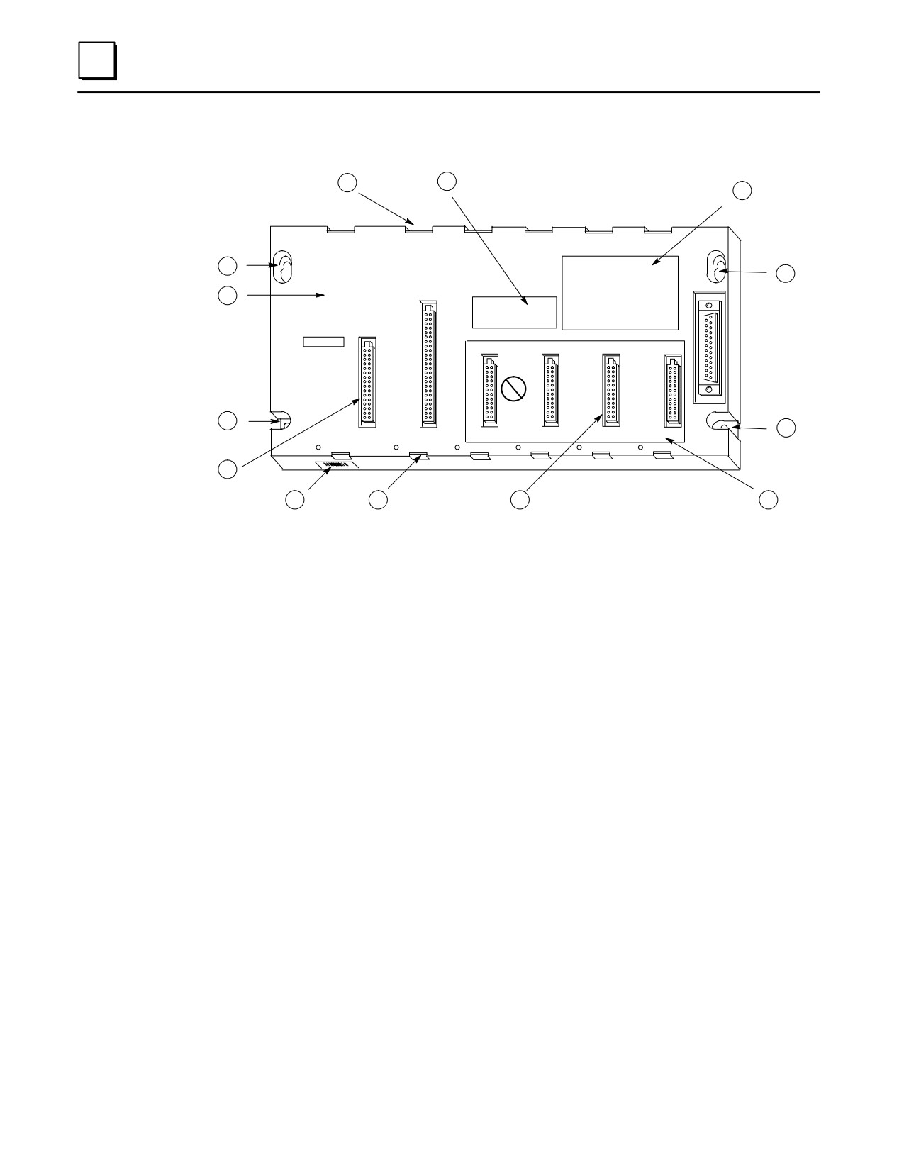
The callouts in the following picture show the items that are common to all Series 90-30
baseplates. Note that a modular CPU baseplate is shown.
3-1
GFK-0356P
3
1
10
9
2
PROGRAMMABLE
2
CONTROLLER
3
BASE 5-SLOT
E
X
P
A
CAUTION
N
NON-CPU SLOTS
USER PROGRAM
S
AND REGISTER
I
VALUES MAY BE
O
LOST IF POWER
N
SUPPLY IS
REMOVED FOR
CP
LONGER THAN
U
1 HOUR
4
CPU/1
I/O-2
I/O-3
I/O-4
I/O-5
4
POWER
SUPPLY
5
6
1
7
8
1.
Module retainers
2.
Upper mounting holes
3.
Baseplate description
4.
Lower mounting holes. The plastic cover is slotted at these two holes to facilitate a
ground connection. See the “Baseplate Safety Grounding” section of the
“Installation” chapter for ground connection details.
5.
Backplane connector for Power Supply
6.
Serial number label
7.
Backplane connectors for I/O or Option modules (slots 2-4) . Note that the slot
labeled CPU/1 is the backplane connector for a CPU module; however, on
Embedded CPU, Expansion, and Remote baseplates, this would be another I/O or
Option module slot.
8.
Slot number labels
9.
Compliance label
10.
Catalog number and certification (UL, CE, etc.) label. On an Embedded CPU
baseplate, this label will be located between Slots 4 and 5.
Figure 3-1. Common Baseplate Features
Two Baseplate Sizes
Series 90-30 baseplates come in two sizes: 5-slot and 10-slot. Be aware that the Power
Supply slot is not numbered, and is not considered to be one of the 5 or 10 slots. So a
5-slot baseplate has slots for a Power Supply and five other modules, and a 10-slot
baseplate has slots for a Power Supply and ten other modules.
3-2
Series 90-30 PLC Installation and Hardware Manual - October 1999
GFK-0356P
3
Baseplate Terms Explained
Backplane: Refers to the circuit board in the baseplate. It contains the baseplate
circuitry and sockets for the plug-in modules.
Rack: This term applies to an assembly consisting of a baseplate, power supply, and
other modules.
Rack Number: In systems that require more than one rack, each rack is given its own
unique number, which enables the CPU to distinguish one rack from another.
Slot Number: Each module location (called a ”slot”) on a baseplate has a unique
number (except for the unnumbered left slot which is for the Power Supply). The slot to
the right of the Power Supply slot is always called Slot 1. These slot numbers are marked
on the baseplate’s plastic cover. Each slot has a connector for module connections and
top and bottom retainers for holding the module in place.
Module Location: Since each rack is assigned a unique number, and since each slot in a
rack’s baseplate has a unique slot number, each individual module’s location in a system
can be identified by its rack and slot numbers. For example, a module could be referred
to as ”the module in Rack 1, Slot 4.” This numbering method enables the CPU to
correctly read from and write to a particular module, and report the location of a faulted
module.
CPU Baseplate: A baseplate that either has a CPU built-in to its backplane circuit board
(embedded CPU) or one that has a slot for a plug-in CPU module (modular CPU). There
can only be one CPU baseplate in a Series 90-30 PLC system and it will always be called
Rack 0 (zero). A CPU module can only mount in Slot 1 of a CPU baseplate. A special
Option module, such as the FIP Remote I/O Scanner module (IC693BEM330) can also be
used in Slot 1 of a CPU baseplate. I/O, Power Supply, and most Option modules cannot
fit in a CPU slot.
Expansion Baseplate: One that does not contain a CPU and which can be mounted up
to 50 cable-feet from the CPU baseplate. An Expansion baseplate cannot operate on its
own. It must be used in a system that has a controlling CPU.
Remote Baseplate: One that does not contain a CPU and which can be mounted up to
700 cable-feet from the CPU baseplate. A remote baseplate cannot operate on its own. It
must be used in a system that has a controlling CPU.
Power Supply Slot: Each baseplate must contain its own Power Supply module, which
must mount in the Power Supply slot. It is the slot located on the left end of the
baseplate, it is not numbered, and it has a unique size and shape so that only a Power
Supply module can mount in it.
Note
Attempts to force a module into an improper slot type will result in
damage to the module and/or the baseplate. Modules will mount in
the correct slot type easily and with a minimum of force.
GFK-0356P
Chapter 3 Baseplates
3-3
3
CPU Baseplates
There are two basic kinds of CPU baseplates, embedded and modular. The embedded
types fulfill the need for a good low cost PLC, but lack the power, expandability, and
versatility of the modular systems.
Embedded CPU Baseplate: This type has CPU and memory integrated circuit chips
soldered to its backplane circuit board.
Modular CPU Baseplate: This type does not have CPU and memory chips on its
backplane. Instead, it has a connector in Slot 1 for a plug-in CPU module which contains
the CPU and memory chips on an internal circuit board.
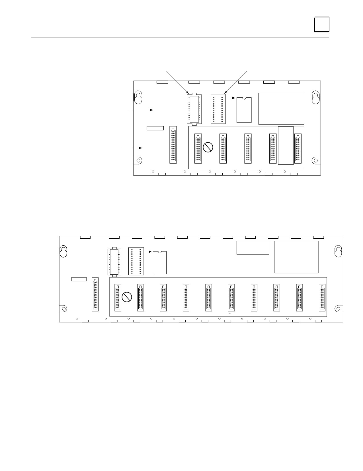
Embedded CPU Baseplates (Figures 3-2 and 3-3)
There are three models of embedded baseplates, the 311, 313, and 323. These model
numbers are based upon the CPU type that each contains. This chapter discusses only
the baseplate features of these products. CPU specifications for the embedded CPU are
located in Chapter 4. The embedded CPU baseplates have the following features:
The CPU type cannot be changed.
They do not support the use of expansion or remote racks, so these racks do
not have an expansion connector like the modular CPU baseplates do.
The models 311 and 313 are 5-slot baseplates, and the model 323 is a 10-slot
baseplate.
Since they do not require a plug-in CPU module, all numbered slots,
including Slot 1, can be used for I/O or Option modules.
The memory back-up battery is located in the Power Supply module; so if
the Power Supply is unplugged from the baseplate, the battery will be
disconnected from the memory circuits, which are located on the backplane
circuit board. However, the backplane circuit board contains a high value
capacitor, sometimes called a ”super capacitor,” that can store enough charge
to maintain the memory circuits for about 1 hour if the Power Supply is
removed or its battery is disconnected. Chapter 6 discusses the
IC693ACC315 Battery Accessory kit that can be used to maintain memory
contents when the Power Supply is removed from an embedded CPU
baseplate.
There are no configuration switches or jumpers on the Model 311, 313, or
323 baseplates.
An embedded CPU baseplate is always assigned, by default, Rack Number
Zero (0).
3-4
Series 90-30 PLC Installation and Hardware Manual - October 1999
GFK-0356P
3
a44563A
Replaceable System (firmware) PROM
Socket for Optional Program PROM
SYSTEM
PROGRAM
PROM
PROM
PROGRAMMABLE
1
CONTROLLER
ÎÎ
Description Label
BASE 5-SLOT
Says ”With CPU”
WITH CPU
ÎÎ
ÎÎ
CAUTION
ÎÎ
NON-CPU SLOTS
USER PROGRAM
AND REGISTER
VALUES MAY BE
Memory Backup
LOST IF POWER
SUPPLY IS
CP
Warning Label
REMOVED FOR
U
LONGER THAN
1 HOUR
I/O-1
I/O-2
I/O-3
I/O-4
I/O-5
POWER
SUPPLY
Figure 3-2. Models IC693CPU311 and IC693CPU313 (5-Slot) Embedded CPU Baseplates
a45134
SYSTEM
PROGRAM
PROM
PROM
1
PROGRAMMABLE
CONTROLLER
BASE 10-SLOT
WITH CPU
CAUTION
NON-CPU SLOTS
NON-CPU SLOTS
USER PROGRAM
AND REGISTER
VALUES MAY BE
LOST IF POWER
SUPPLY IS
CP
REMOVED FOR
U
LONGER THAN
1 HOUR.
POWER
I/O-1
I/O-2
I/O-3
I/O-4
I/O-5
I/O-6
I/O-7
I/O-8
I/O-9
I/O-10
SUPPLY
Figure 3-3. Model IC693CPU323 (10-slot) Embedded CPU Baseplate
GFK-0356P
Chapter 3 Baseplates
3-5
3
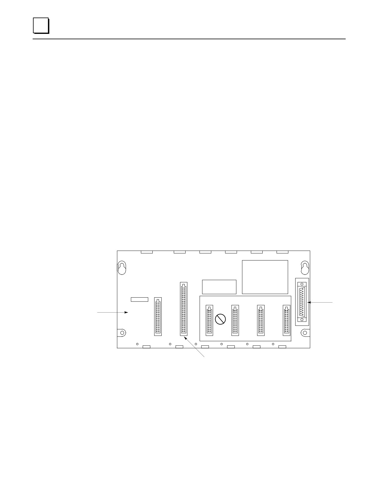
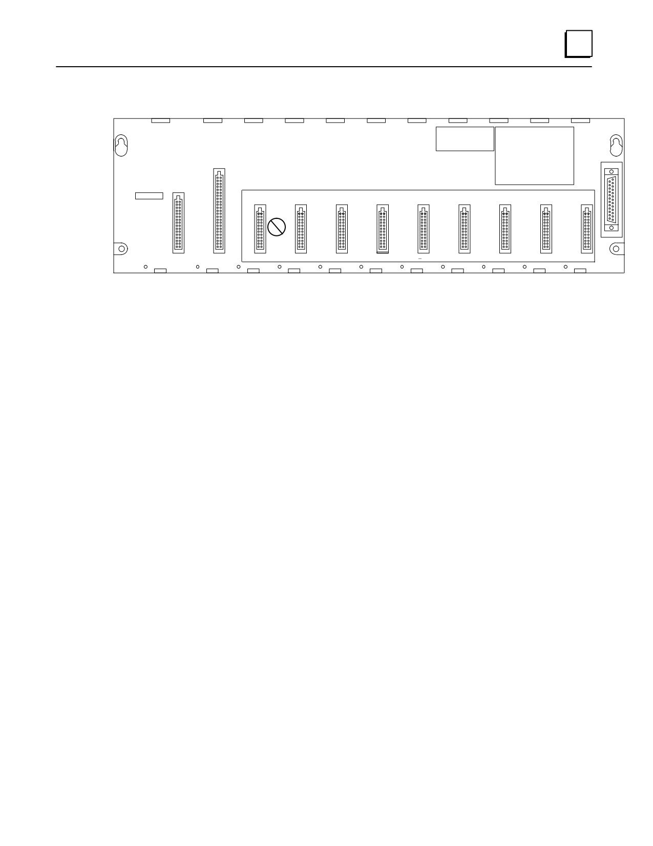
Modular CPU Baseplates (Figures 3-4 and 3-5)
A Power Supply module must be plugged into the left slot (which is not
numbered) of these baseplates. The left slot is a unique size and type that
only supports a Power Supply module.
A CPU module (or a special Option module) must be installed in Slot 1 of
these baseplates. Slot 1 is a unique size and type that only supports a CPU
module or a special Option module like the FIP Remote I/O Scanner
(IC693BEM330). Slot 1 is labeled CPU/1.
Slots numbered 2 and above are of a unique size and type that only
supports I/O or Option modules.
Expansion and Remote baseplates are supported, so a 25-pin D-type female
expansion connector is located at the right end of the baseplate for
connecting to an Expansion or Remote baseplate.
Since the CPU is modular, it can be replaced or changed to a different type if
additional features are desired.
Only one CPU baseplate is allowed per system. If more than one baseplate
is used in a system, the additional ones must be either Expansion or Remote
types.
A modular CPU baseplate is always assigned, by default, Rack Number 0.
a44564
PROGRAMMABLE
CONTROLLER
BASE 5-SLOT
E
X
P
A
CAUTION
NON-CPU SLOTS
N
USER PROGRAM
S
I/O Bus
Memory Backup
AND REGISTER
I
Expansion
Warning Label
VALUES MAY BE
O
LOST IF POWER
Connector
SUPPLY IS
N
REMOVED FOR
CP
LONGER THAN
U
1 HOUR
CPU/1
I/O-2
I/O-3
I/O-4
I/O-5
POWER
SUPPLY
CPU Slot (Slot 1)
Figure 3-4. IC693CHS397 5-Slot Modular CPU Baseplate
3-6
Series 90-30 PLC Installation and Hardware Manual - October 1999
GFK-0356P
3
a43049
PROGRAMMABLE
CONTROLLER
BASE 10-SLOT
E
X
P
A
CAUTION
NON-CPU SLOTS
NON-CPU SLOTS
N
USER PROGRAM
S
AND REGISTER
I
VALUES MAY BE
O
LOST IF POWER
N
SUPPLY IS
CP
REMOVED FOR
U
LONGER THAN
1 HOUR.
CPU/1
I/O-2
I/O-3
I/O-4
I/O-5
I/O-6
I/O-7
I/O-8
I/O-9
I/O-10
POWER
SUPPLY
Figure 3-5. IC693CHS391 10-Slot Modular CPU Baseplate
GFK-0356P
Chapter 3 Baseplates
3-7
3
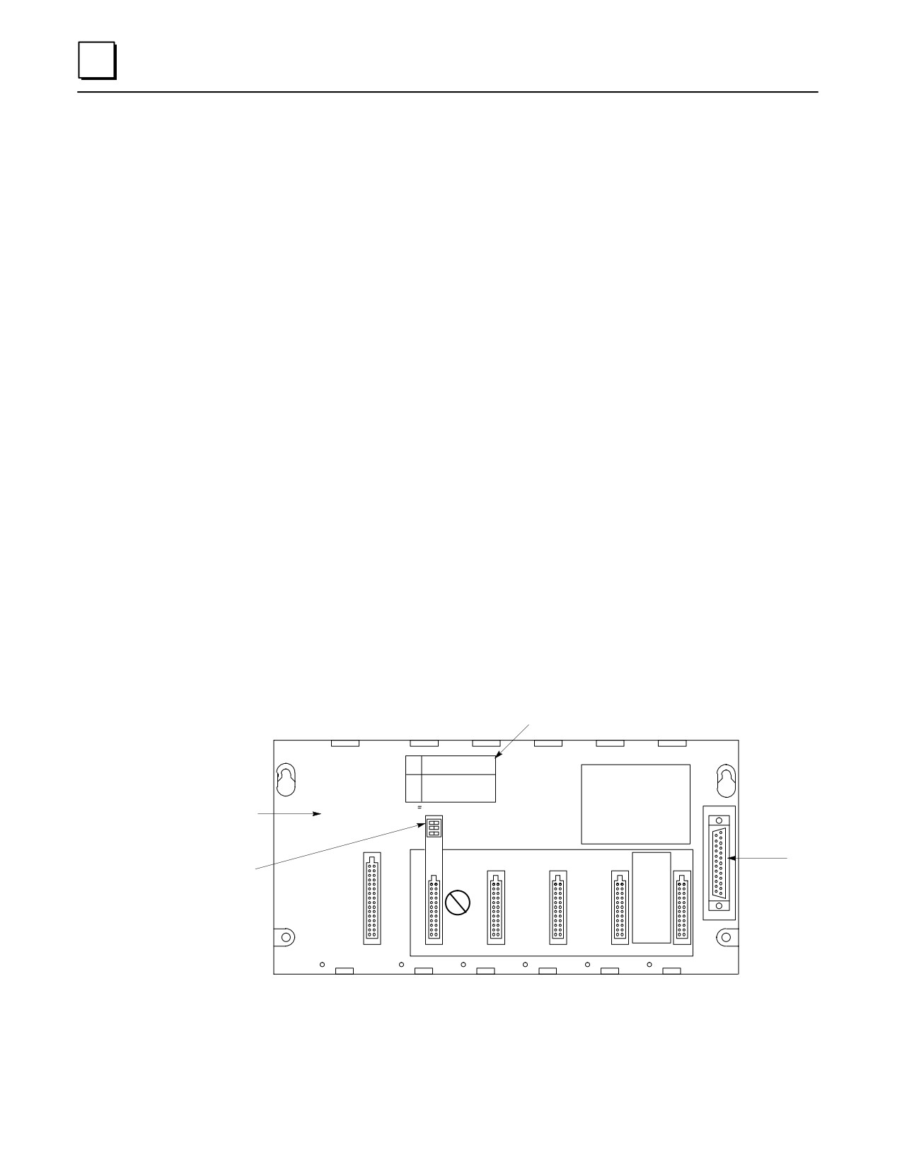
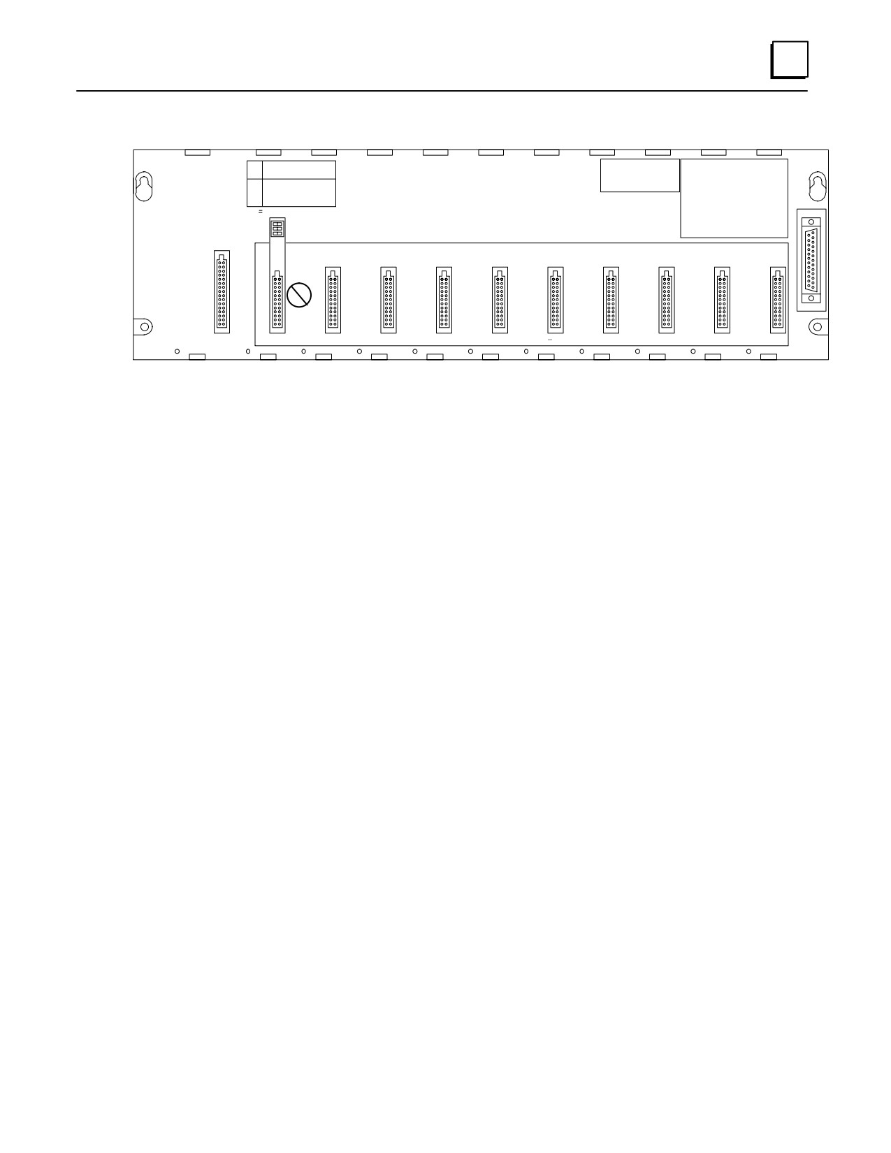
Expansion Baseplates (Figures 3-6 and 3-7)
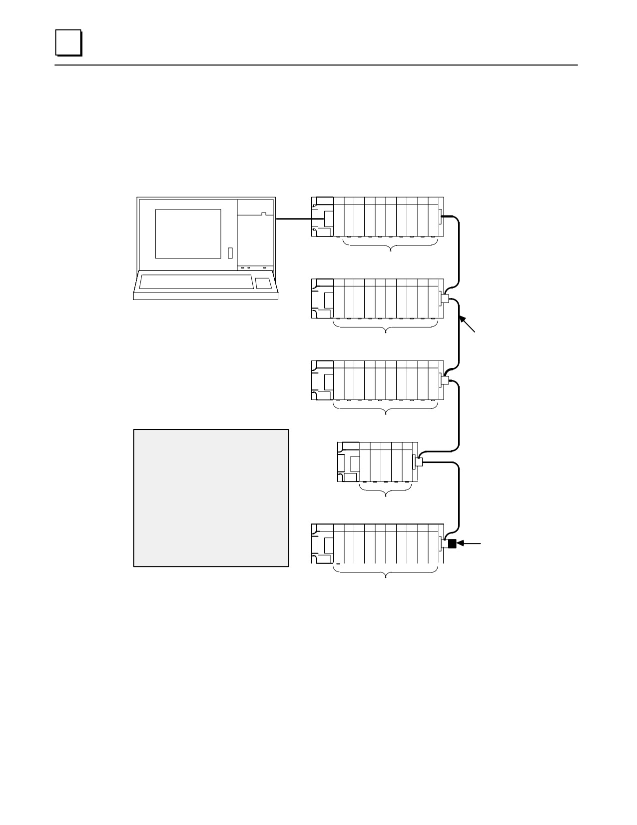
There can be no more than a total of 50 feet (15 meters) of cable
interconnecting Expansion baseplates and the CPU baseplate.
An Expansion baseplate cannot stand alone. It must be connected to a
system that has a CPU. The CPU can be in a PLC or in a Personal Computer
that is equipped with a Personal Computer Interface Card (see Chapter 11).
Maximum number of Expansion baseplates allowed per system depends on
the type of CPU they are used with. For CPUs 331, 340, and 341, the
maximum is 4. For CPUs numbered 350 and higher, the maximum is 7.
Each Expansion baseplate has a 25-pin female D-type I/O Bus Expansion
connector mounted at its right end for connection to other baseplates.
Available in two versions; 5-slot (IC693CHS398) and 10-slot (IC693CHS392)
An Expansion backplane does not support the following intelligent option
modules: PCM, ADC, BEM330, and CMM. These modules must be mounted
in a CPU baseplate. All other I/O and option modules can be mounted in any
type of rack.
All Expansion baseplates must be connected to a common ground (see the
“Installation” chapter for details).
Expansion baseplates are the same physical size, use the same type power
supplies, and support the same I/O and option modules as the Remote
baseplates.
Each Expansion baseplate has a Rack Number Selection DIP switch.
Rack Number Selection
Switch Setting Label
a44565
DIP
EXPANSION RACK
#
SW
1
2
3
4
5
6
7
1
X
X
X
PROGRAMMABLE
2
X
X X
CONTROLLER
3
X
X X
Description Label
BASE 5-SLOT
X CLOSED
Says ”Expansion”
EXPANSION
E
X
P
A
Rack Number
NON-CPU SLOTS
N
Expansion
Selection Switch
S
Connector
I
O
N
CP
U
I/O-1
I/O-2
I/O-3
I/O-4
I/O-5
POWER
SUPPLY
Figure 3-6. IC693CHS398 5-Slot Expansion Baseplate
3-8
Series 90-30 PLC Installation and Hardware Manual - October 1999
GFK-0356P
3
a43050
DIP
EXPANSION RACK
#
SW
1
2
3
4
5
6
7
1
X
X
X
PROGRAMMABLE
2
X
X X
CONTROLLER
3
X
X X
BASE 10-SLOT
X CLOSED
EXPANSION
E
X
P
NON-CPU SLOTS
NON-CPU SLOTS
A
N
S
I
O
N
CP
U
I/O-1
I/O-2
I/O-3
I/O-4
I/O-5
I/O-6
I/O-7
I/O-8
I/O-9
I/O-10
POWER
SUPPLY
Figure 3-7. IC693CHS392 10-Slot Expansion Baseplate
GFK-0356P
Chapter 3 Baseplates
3-9
3
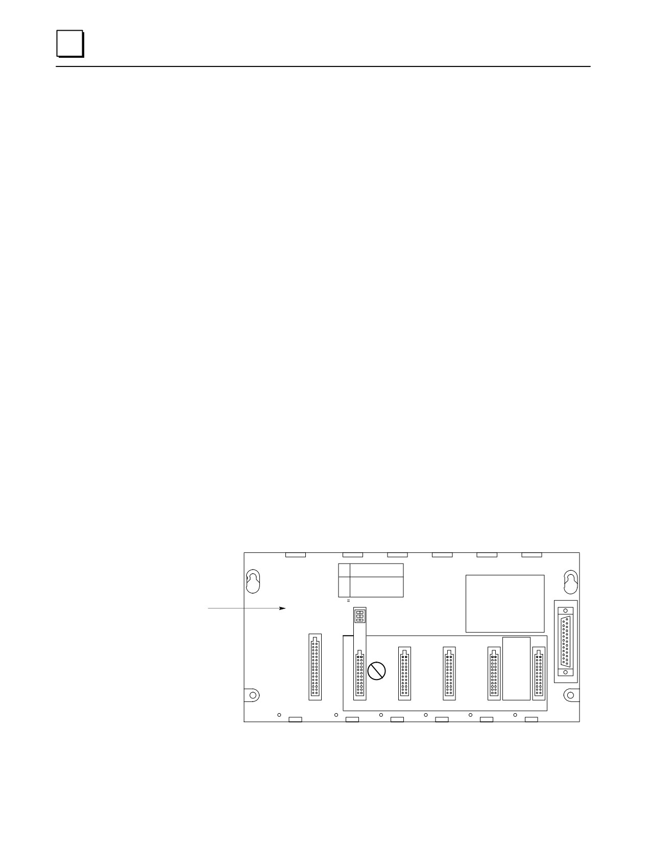
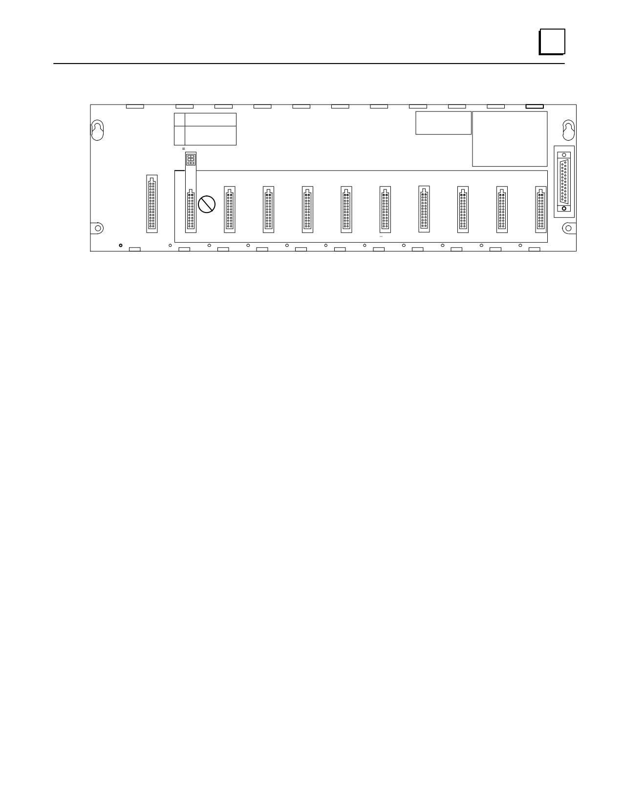
Remote Baseplates (Figures 3-8 and 3-9)
There can be no more than 700 feet of cable connecting all baseplates in a
system that uses Remote baseplates.
A Remote baseplate cannot stand alone. It must be connected to a system
that has a CPU. The CPU can be in a PLC or in a Personal Computer that is
equipped with a Personal Computer Interface Card (see Chapter 11).
Remote capability is facilitated by the Remote baseplate’s built-in isolation
between the +5 volt logic supply used by the I/O modules residing in the
Remote baseplate and the supply for the interface circuit associated with the
I/O Bus Expansion Interface. Isolation helps prevent problems associated
with unbalanced ground conditions.
Maximum number of Remote baseplates allowed per system depends on
the type of CPU they are used with. For CPUs 331, 340, and 341, the
maximum is 4. For CPUs numbered 350 and higher, the maximum is 7.
Each remote baseplate has a 25-pin female D-type Expansion connector
mounted at its right end for connection to other baseplates.
Remote baseplates are available in two sizes; 5-slot (IC693CHS398) and 10-slot
(IC693CHS392)
A Remote backplane does not support the following intelligent option
modules: PCM, ADC, BEM330, and CMM. These modules must be mounted
in a CPU baseplate. All other I/O and option modules can be mounted in any
type of baseplate.
Remote baseplates are the same physical size, use the same type power
supplies, and support the same I/O and option modules as the Expansion
baseplates.
Each Remote baseplate has a Rack Number Selection DIP switch.
a44968
DIP
EXPANSION RACK
#
SW
1
2
3
4
5
6
7
1
X
X
X
2
X
X X
PROGRAMMABLE
CONTROLLER
3
X
X X
Description Label
X CLOSED
BASE 5-SLOT
Says ”Remote”
REMOTE
E
X
P
A
N
NON-CPU SLOTS
S
I
O
C
N
P
U
I/O-1
I/O-2
I/O-3
I/O-4
I/O-5
POWER
SUPPLY
Figure 3-8. IC693CHS399 5-Slot Remote Baseplate
3-10
Series 90-30 PLC Installation and Hardware Manual - October 1999
GFK-0356P
3
a44969
DIP
EXPANSION RACK
#
SW
1
2
3
4
5
6
7
1
X
X
X
PROGRAMMABLE
2
X
X X
CONTROLLER
3
X
X X
BASE 10-SLOT
X CLOSED
REMOTE
E
X
P
A
NON-CPU SLOTS
NON-CPU SLOTS
N
S
I
O
CP
N
U
I/O-1
I/O-2
I/O-3
I/O-4
I/O-5
I/O-6
I/O-7
I/O-8
I/O-9
I/O-10
POWER
SUPPLY
Figure 3-9. IC693CHS393 10-Slot Remote Baseplate
GFK-0356P
Chapter 3 Baseplates
3-11
3
I/O Bus Expansion Cables
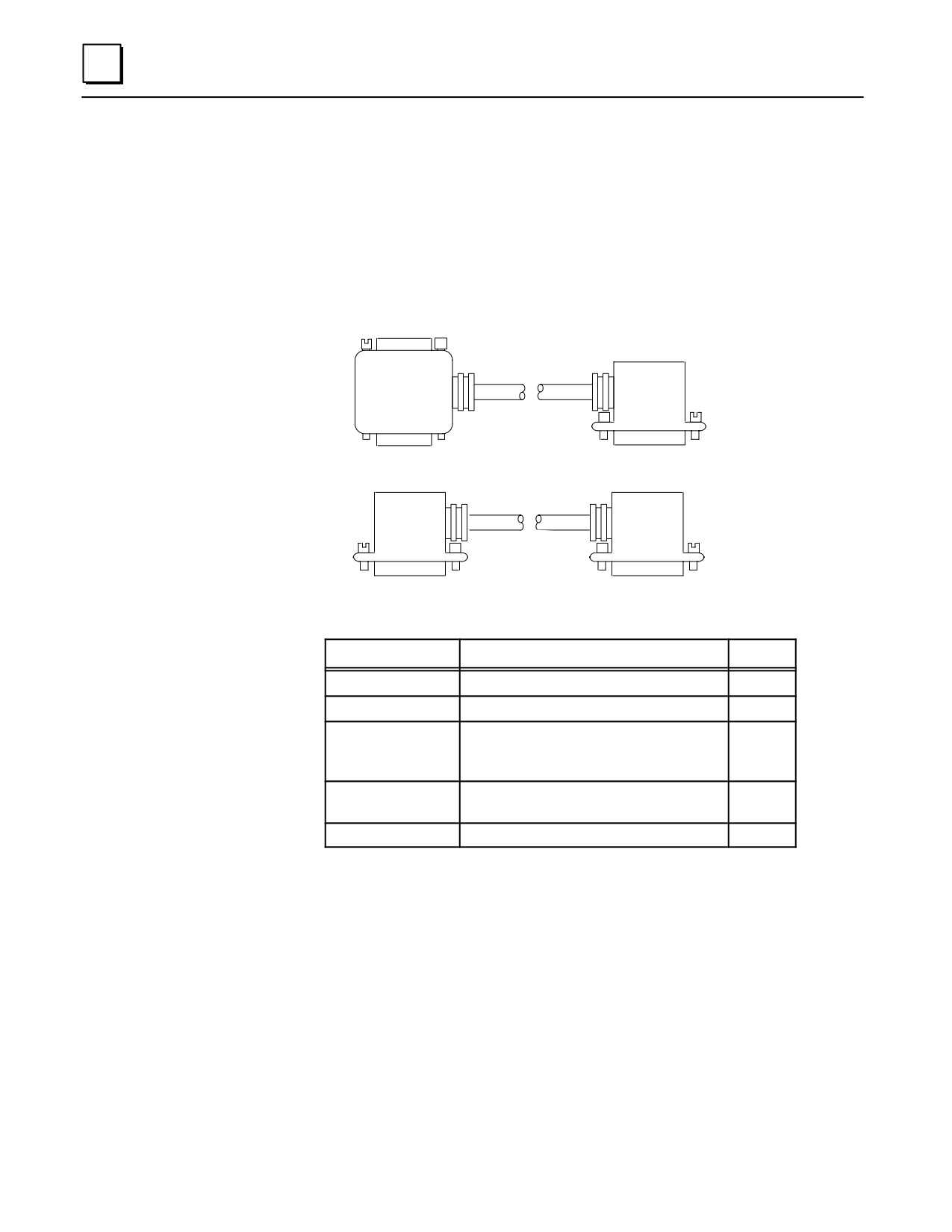
Five prewired I/O Bus Expansion cables are available from GE Fanuc. Catalog numbers and
lengths of these cables are listed in the following figure. You can build custom cables to suit
the needs of your application if cable lengths other than those listed are required. Refer to
the “Cables” chapter for detailed information on cable type and connectors. Note that the
same cables can be used with both Expansion and Remote baseplates, however the cables
used in a remote expansion system must use the cable type described in the “Cables”
chapter.
FEMALE
a43853A
CONNECTOR
ÎÎ Î
ÎÎ
Î
ÎÎ
Figure A
ÎÎ
.5, 3, 6, 26 FOOT
ÎÎ
ÎÎ
CABLES
ÎÎ
Î
MALE
MALE
CONNECTOR
CONNECTOR
ÎÎ
ÎÎ
ÎÎ
ÎÎ
ÎÎ
Figure B
ÎÎ
ÎÎ
ÎÎ
CABLE
MALE
MALE
CONNECTOR
CONNECTOR
Catalog Number
Length
Figure
IC693CBL300
3 feet (1 meter), continuous shield
A
IC693CBL301
6 feet (2 meters), continuous shield
A
IC693CBL302
50 feet (15 meters), continuous
B
shield with built in terminator (this
is not a Wye cable)
IC693CBL312
0.5 feet (.15 meters), continuous
A
shield
IC693CBL313
25 feet (8 meters), continuous shield
A
Figure 3-10. I/O Bus Expansion Cables
Note
The 3 foot cable (IC693CBL300) can be used as a Wye adapter between
custom-built cables and Remote baseplates.
Differences Between Remote and Expansion Racks
Basically, Remote racks provide the same functionality as Expansion racks, but with the
longer distance (700 feet/213 meters verses 50 feet/15 meters for Expansion racks)
capability. To minimize unbalanced ground conditions, Remote baseplates have extra
3-12
Series 90-30 PLC Installation and Hardware Manual - October 1999
GFK-0356P
3
isolation circuitry. Unbalanced ground conditions can occur when systems are located
long distances from each other and do not share the same ground system. However,
distance is not always the problem; even racks that are mounted near each other can
experience problems if the system is not grounded properly. See Chapter 2 for
grounding information.
The use of Remote racks requires a special consideration pertaining to scan time. In
order to operate at long distances, the I/O Bus runs at a lower clock speed (compared to
that used for Expansion racks) when communicating with Remote racks, which will
have an impact on performance. The impact will be relatively small for discrete I/O and
slightly more for other modules, such as the High Speed Counter or Genius
Communications Module. The increase in time needed to communicate with modules in
a remote baseplate will usually be small with respect to the overall scan time. For more
detailed information on scan time calculations, refer to Chapter 2 of GFK-0467, the Series
90-30/20/Micro PLC CPU Instruction Set Reference Manual.
Another important scan time consideration is the cable type used for communicating at
longer distances. Data propagation delay must be minimized to ensure proper system
timing and margins. Any deviation in cable type may result in erratic or improper
system operation. Suggested cable types are specified in the “Cables” chapter in the
IC693CBL300/etc. data sheet.
Mixing Expansion and Remote Baseplates in a System
Expansion and remote baseplates can be used in the same system as long as certain
requirements are met:
You do not exceed the 50 foot (15 meter) maximum cable distance from the
CPU to the last Expansion baseplate
You do not exceed the 700 foot (213 meter) maximum cable distance from
the CPU to the last Remote baseplate.
The cable type recommended for use with Remote baseplates must be used
throughout the system. The exception to this requirement is that the
prewired 3 foot (1 meter) cable, IC693CBL300, can be used as a Wye adapter
to simplify the custom cable assembly associated with the “daisy chain”
connections between baseplates. Information on building cables for use
with Remote baseplates can be found in the “Cables” chapter in the
IC693CBL300/etc. data sheet..
Termination Requirement for Expansion or Remote System
When two or more baseplates are connected via the I/O Bus Expansion System, the I/O
Expansion Bus must be properly terminated. The most common method of terminating
the I/O Expansion Bus is by installing a termination resistor pack (IC693ACC307) on the
open connector on the last (most distant from the CPU) Expansion or Remote baseplate
in the system. The resistor pack is physically mounted inside of a connector. Although a
termination resistor pack is shipped with each baseplate, only the last baseplate in the
chain needs to have this termination connector installed. Unused termination packs can
be discarded. The prewired 50 foot (15 meter) cable (IC693CBL302) has termination
resistors wired inside the connector on one end of the cable. This cable can be used if
only one expansion rack is needed in a system and a 50 foot cable link is required (the
IC693ACC307 resistor pack is not needed in this case). Also, a custom-built cable with
built-in resistors would eliminate the need for the IC693ACC307 resistor pack.
GFK-0356P
Chapter 3 Baseplates
3-13

3
Powering Down Individual Expansion or Remote Baseplates
Expansion or Remote baseplates can be powered-down individually without affecting the
operation of other baseplates; however, powering off a baseplate generates a loss of module
(LOSS_OF_MODULE) fault in the PLC Fault Table for each module in the baseplate. When
this fault condition occurs, and until the baseplate is powered back on and all modules
recovered, the lost I/O modules are not scanned. For more information on the power-up
and power-down sequence, see Chapter 2 in the Series 90-30 Programmable Controller
Reference Manual, GFK-0467.
Series 90-30 PLC Backplane
The Series 90-30 PLC backplane (on all three types of baseplates) has a dedicated I/O
communications bus. The signals on the remote baseplate backplane are optically coupled
and an isolated DC-DC power supply converter is provided to isolate the signals from other
backplanes.
Power bus - connects the power supply outputs to the modules in the
baseplate.
I/O Communications bus - the CPU communicates with I/O modules over
this bus. This bus is connected to the I/O busses in Expansion and Remote
racks via the I/O Bus Expansion connectors and cables.
Special Intelligent Module bus - exists only on a CPU baseplate; therefore,
certain special intelligent option modules, such as the PCM, ADC, and CMM
modules, will only work in a CPU baseplate.
Rack Number DIP Switch on Expansion and Remote Baseplates
Each baseplate in a Series 90-30 system is identified with a unique number called a “Rack
Number.” Rack Numbers for Expansion and Remote baseplates are selected by setting a
DIP switch located on each baseplate directly above the connector for Slot 1. Rack number
0 must always be present and is assigned, by default, to the CPU rack (the CPU baseplate
does not have this DIP switch). Racks do not need to be contiguously numbered, although
for consistency and clarity, it is recommended that rack numbers not be skipped (use 1, 2, 3 -
not 1, 3, 5). Rack numbers must not be duplicated within a system. The following table
shows the DIP switch positions for rack number selection.
Table 3-1. Rack Number Selection Switch Settings
Rack Number
DIP Switch
1
2
3
4
5*
6*
7*
1
open
closed
open
closed
open
closed
open
2
closed
open
open
closed
closed
open
open
3
closed
closed
closed
open
open
open
open
* Rack numbers 5, 6, and 7 only valid for CPUs 350 and higher.
3-14
Series 90-30 PLC Installation and Hardware Manual - October 1999
GFK-0356P
3
The particular CPU module used determines how may expansion and remote baseplates
are allowed:
The 331, 340, and 341 CPUs support a total of 4 Expansion and/or Remote
racks.
The 350, 351, 352, 360, 363, and 364 CPUs support a total of 7 Expansion
and/or Remote racks.
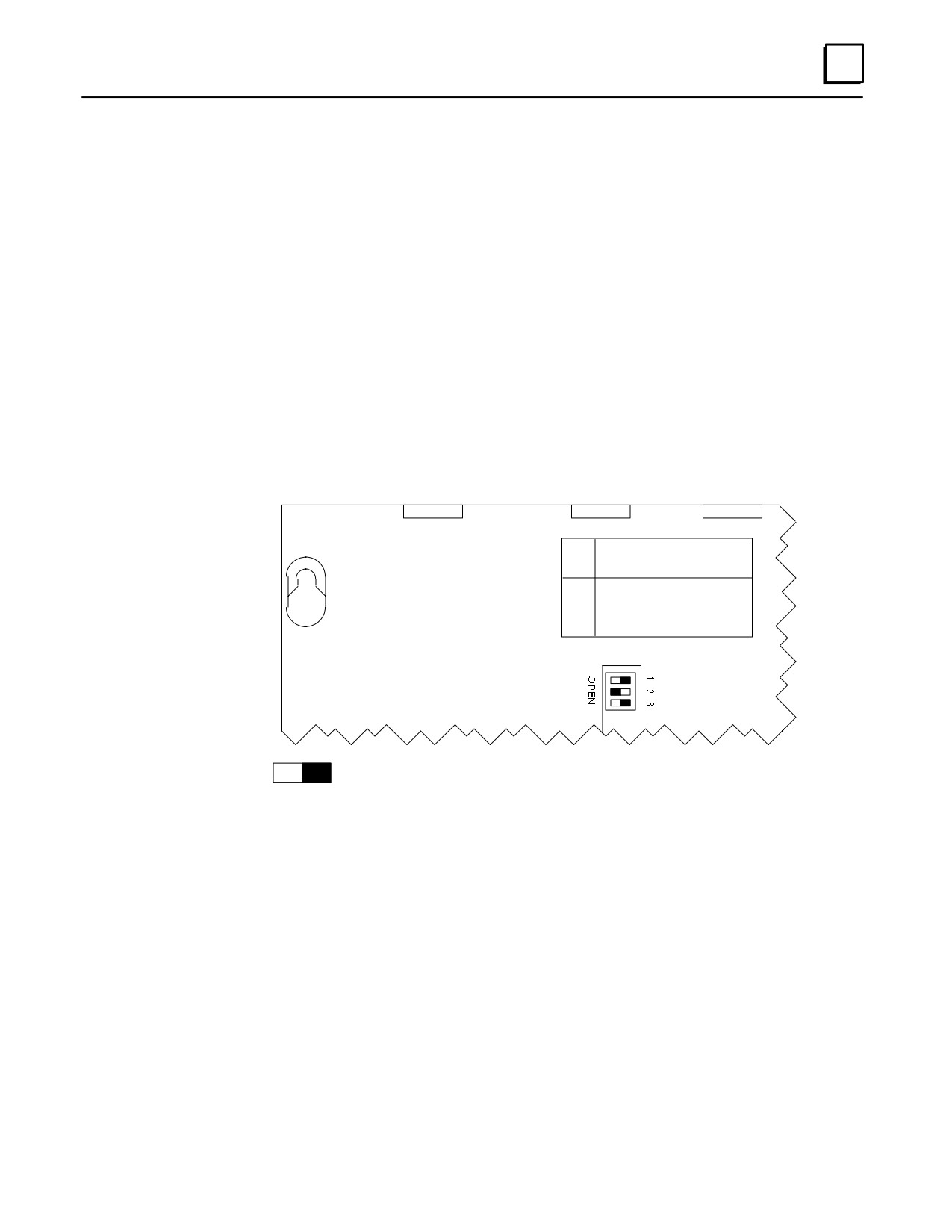
Each baseplate has a label above the DIP switch that shows the settings for each rack
number. The following figure shows this DIP switch package with an example of rack
#2 number selected.
Note
Use a ball-point pen to set the DIP switches. In general, it is best to
avoid using a pencil to set DIP switches since graphite (a gritty,
conductive material) from the pencil can enter and damage the switch.
a43054
DIP
EXPANSION RACK #
GEFanuc
SW
1
2
3
4
5
6
7
SERIES 90-30
1
X
X
X
PROGRAMMABLE
2
X
X
X
CONTROLLER
3
X
X
X
X = CLOSED
BASE 10-SLOT
EXPANSION
= CLOSED (Switch pushed down on right side)
Figure 3-11. Rack Number Selection Switch (Shown with Rack 2 Selected)
GFK-0356P
Chapter 3 Baseplates
3-15
3
Expansion Rack Connection Example
The following example shows a system that includes Expansion baseplates.
PROGRAMMER
CPU BASEPLATE
a47057
ÎÎÎÎÎ
ÎÎ
SERIAL
C
P
ÎÎÎÎÎ
Î
NOTE
U
TOTAL MAXIMUM
ÎÎÎÎÎ
ÎÎÎÎÎÎÎÎ
DISTANCE FROM
ÎÎÎÎÎÎ
DISCRETE/ANALOG/OPTION
CPU BASEPLATE
TO LAST EXPANSION
ÎÎÎÎÎÎÎÎ Î
EXPANSION BASEPLATE
BASEPLATE IS
50 FEET (15 METERS)
ÎÎÎÎÎÎÎÎÎÎ
Î
Î
ÎÎÎÎÎÎÎÎÎÎ
Î
Î
ÎÎÎÎÎÎÎÎ
I/O EXPANSION CABLES
DISCRETE/ANALOG/OPTION
EXPANSION BASEPLATE
Î
Î
Î
Î
ÎÎÎÎÎÎÎÎ
DISCRETE/ANALOG/OPTION
EXPANSION BASEPLATE
*NOTE
ÎÎ
Each signal pair on the I/O bus must
ÎÎ
be terminated at the end of the I/O
bus with120 ohm resistors. This ter-
ÎÎÎ
mination can be done with the I/O
Bus Terminator Plug (IC693ACC307),
DISCRETE/ANALOG/OPTION
by using the 50 foot (15 meter) cable
(IC693CBL302) with built-in terminat-
EXPANSION BASEPLATE
ing resistors, or by building a custom
I/O BUS
Î
TERMINATOR
cable with the resistors installed in
the connector at the end of the bus.
PLUG (See *NOTE)
Î
IC693ACC307
ÎÎÎÎÎÎÎÎ
DISCRETE/ANALOG/OPTION
Figure 3-12. Example of Connecting Expansion Baseplates
3-16
Series 90-30 PLC Installation and Hardware Manual - October 1999
GFK-0356P
3
Expansion and Remote Baseplates Connection Example
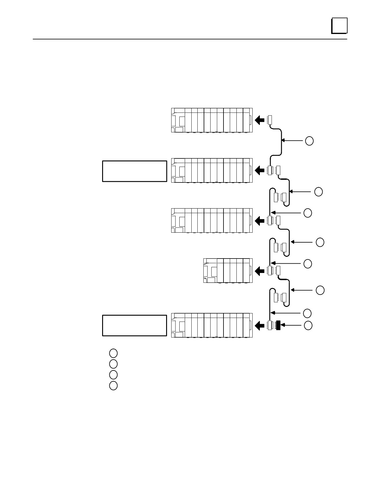
The following example shows cable connections in a system that includes both remote
and expansion baseplates. A system can have a combination of remote and expansion
baseplates as long as the distance and cable requirements are followed.
CPU BASEPLATE
a44965A
CPU
C
BASEPLATE
P
IC693CHS391/397
U
1
EXPANSION
BASEPLATE
EXPANSION BASEPLATE
IC693CHS392/398
Maximum Cable Distance
from CPU = 50 Feet
(15 METERS)
2
REMOTE BASEPLATE
3
REMOTE
BASEPLATE
IC693CHS393/399
2
REMOTE BASEPLATE
ÎÎ
REMOTE
3
BASEPLATE
ÎÎÎ
IC693CHS393/399
ÎÎÎ
2
REMOTE
BASEPLATE
REMOTE BASEPLATE
IC693CHS393/399
3
Maximum Cable Distance
from CPU = 700 Feet
4
(213 METERS)
1
Standard Wye Cable
2
Custom Built Point-to-Point Cable
3
IC693CBL300 Standard Wye Cable, Used as Wye Jumper
4
IC693ACC307 Bus Terminator
Figure 3-13. Example of Connecting Expansion and Remote Baseplates
GFK-0356P
Chapter 3 Baseplates
3-17
3
Baseplate Mounting Dimensions
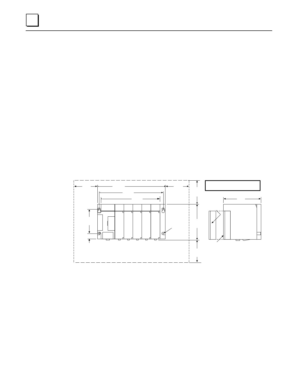
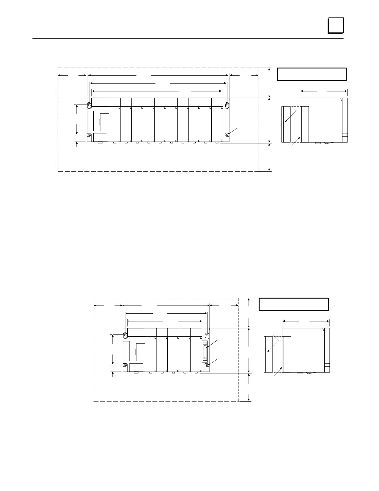
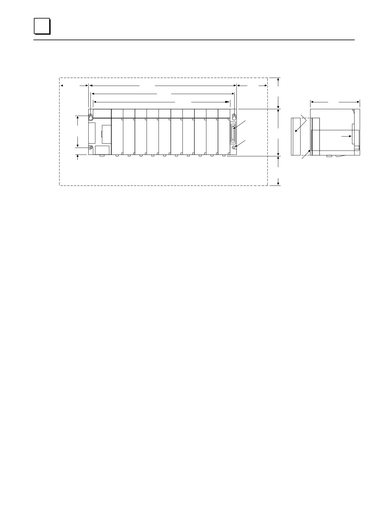
Series 90-30 PLC baseplates are designed to be panel mounted. Each baseplate has
standard attachment flanges for mounting on an electrical panel. Baseplate dimensions
and proper spacing requirements for installation purposes for both the 5 and 10-slot
baseplates with embedded CPU (Models 311 and Model 313 are 5-slot baseplates; Model
323 is a 10-slot baseplate), and the 5 and 10-slot baseplates for Modular CPUs are shown
in figures 3-1 through 3-4.
Note
All 5-slot baseplates have the same mounting dimensions and all 10-slot
baseplates have the same mounting dimensions. Baseplates must be
mounted in the orientation as shown in the following figures for proper cooling.
Embedded CPU (311, 313, and 323) Baseplate Dimensions
Baseplate dimensions and spacing requirements for installation for Models 311, 313, and
323 baseplates are shown below.
a45422
* 4.00
10.43
*
4.00
DIMENSIONS IN INCHES,
(102)
(265)
(102)
4.00
MILLIMETERS ARE IN PARENTHESIS
9.84
(250)
(102)
8.60
REMOVABLE
5.59
(218)
I/O
(142)
TERMINAL
ÎÎ
POWER
BLOCK
SUPPLY
ÎÎÎÎÎÎ
ÏÏ
ÎÎ
.20 DIA.
3.54
ÎÎÎÎÎÎ
(5.08)
5.12
ÏÏ
ÎÎ
(90)
(TYPICAL)
(130)
ÎÎÎÎÎÎ
ÏÏ
ÎÎ
ÎÎÎÎÎÎ
ÏÏ
ÎÎ
ÎÎÎÎÎÎ
ÏÏ
ÎÎ
.79
HINGED
SIDE VIEW
(20)
DOOR
4.00
(102)
* ALLOWANCE FOR COOLING
Figure 3-14. Model 311 and 313 5-Slot Baseplate Dimensions and Spacing Requirements
3-18
Series 90-30 PLC Installation and Hardware Manual - October 1999
GFK-0356P
3
a45421
DIMENSIONS IN INCHES,
* 4.00
17.44
4.00
MILLIMETERS ARE IN PARENTHESIS
(102)
(443)
(102)
4.00
16.85
(428)
(102)
REMOVABLE
15.60
5.59
I/O
(396)
(142)
TERMINAL
POWER
BLOCK
SUPPLY
Î
ÎÎÎÎÎÎÎÎÎÎÎÎÎ
.20 DIA.
Ï
Î
3.54
(5.08)
5.12
(90)
ÎÎÎÎÎÎÎÎÎÎÎÎÎ
(TYPICAL)
(130)
Ï
Î
ÎÎÎÎÎÎÎÎÎÎÎÎÎ
Ï
Î
ÎÎÎÎÎÎÎÎÎÎÎÎÎ
Ï
Î
FRONT VIEW
.79
HINGED
SIDE VIEW
(20)
DOOR
4.00
(102)
* ALLOWANCE FOR COOLING
Figure 3-15. Model 323 10-Slot Baseplate Dimensions and Spacing Requirements
Modular CPU, Expansion, and Remote Baseplate Dimensions
Baseplate dimensions and spacing requirements for installation for Modular CPU
baseplates are shown below.
a45424
* 4.00
10.43
4.00
DIMENSIONS IN INCHES,
(102)
(265)
(102)
4.00
MILLIMETERS ARE IN PARENTHESIS
9.84
(250)
(102)
8.60
REMOVABLE
5.59
(218)
I/O
(142)
TERMINAL
ÎÎ
POWER
SEE
BLOCK
SUPPLY
ÎÎÎÎÎÎ
NOTE
ÏÏ
ÎÎ
3.54
ÎÎÎÎÎÎ
.20 DIA.
ÏÏ
ÎÎ
(5.08)
5.12
(90)
(TYPICAL)
(130)
ÎÎÎÎÎÎ
ÏÏ
ÎÎ
ÎÎÎÎÎÎ
ÏÏ
ÎÎ
ÎÎÎÎÎÎ
ÏÏ ÎÎ
FRONT VIEW
.79
HINGED
SIDE VIEW
(20)
DOOR
NOTE:
4.00
IF THE CABLE IS USED, ALLOW ABOUT 6 INCH HORIZONTAL CLEARANCE
(102)
ON THE RIGHT SIDE OF THE RACK FOR ACCESS TO THE CONNECTOR.
* ALLOWANCE FOR COOLING
Figure 3-16. Modular CPU, Expansion, and Remote 5-Slot Baseplate Dimensions and
Spacing Requirements
GFK-0356P
Chapter 3 Baseplates
3-19
3
a45423
DIMENSIONS IN INCHES,
* 4.00
17.44
* 4.00
MILLIMETERS ARE IN PARENTHESIS
(102)
(443)
(102)
4.00
16.85
(428)
(102)
REMOVABLE
15.60
I/O
5.59
(396)
TERMINAL
(142)
ÎÎ
POWER
SEE
BLOCK
SUPPLY
ÎÎÎÎÎÎÎÎÎÎÎÎ
NOTE
ÏÏ
ÎÎ
.20 DIA.
3.54
ÎÎÎÎÎÎÎÎÎÎÎÎÎ
ÏÏ
ÎÎ
(5.08)
5.12
(90)
CONNECTOR
ÎÎÎÎÎÎÎÎÎÎÎÎÎ
(TYPICAL)
(130)
ÏÏ
FOR
ÎÎ
EXPANSION
ÎÎÎÎÎÎÎÎÎÎÎÎÎ
ÏÏ
CABLE
ÎÎ
ÎÎÎÎÎÎÎÎÎÎÎÎÎ
ÏÏ
ÎÎ
FRONT VIEW
HINGED
.79
NOTE:
SIDE VIEW
(20)
IF THE CABLE IS USED, ALLOW ABOUT 6 INCH HORIZONTAL CLEARANCE
DOOR
ON THE RIGHT SIDE OF THE RACK FOR ACCESS TO THE CONNECTOR.
4.00
(102)
* ALLOWANCE FOR COOLING
Figure 3-17. Modular CPU, Expansion, and Remote 10-Slot Baseplate Dimensions and
Spacing Requirements
3-20
Series 90-30 PLC Installation and Hardware Manual - October 1999
GFK-0356P
3
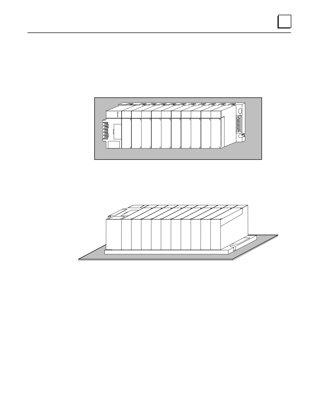
Load Ratings, Temperature, and Mounting Position
The power supply load rating depends on the mounting position of the baseplate and
the ambient temperature.
The load rating with the baseplate mounted upright on a panel is:
100% at 60 C (140 F)
ÎÎ
ÎÎ
Î
Power supply load ratings with the baseplate mounted horizontally are:
temperature at 25 C (77 F) - full load
temperature at 60 C (140 F) - 50% of full load
GFK-0356P
Chapter 3 Baseplates
3-21
3
Baseplate Adapter Brackets for 19” Rack Mounting
Two optional Baseplate Adapter Brackets allow a 10-slot baseplate to be mounted in a 19
inch rack. Each baseplate installation requires only one of the adapter brackets.
Warning
Be sure to follow grounding instructions in Chapter 2 when using
these adaptor brackets. Failure to properly ground the PLC can result
in improper operation, damage to equipment, and injury to personnel.
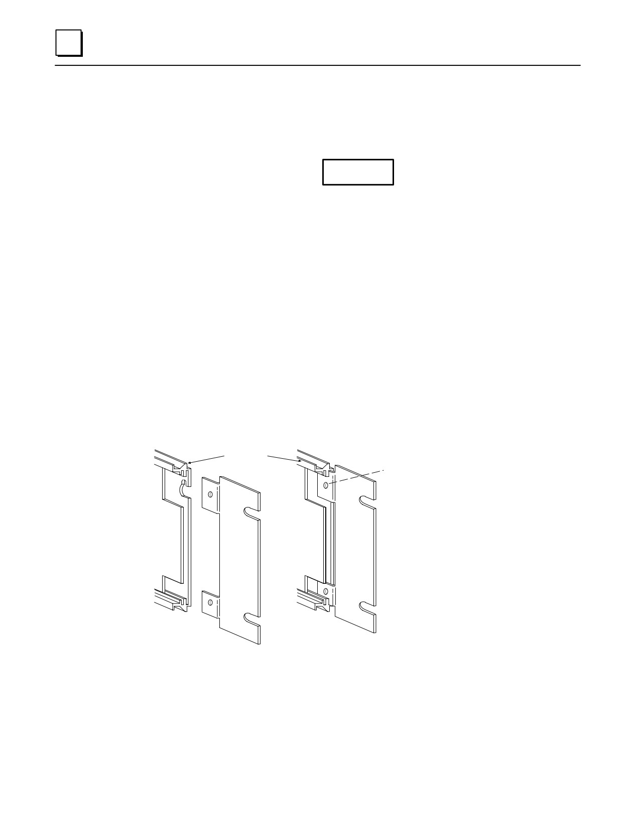
IC693ACC308 Front Mount Adapter Bracket. Used to mount a baseplate to the
front face of a 19” rack. Install the adapter bracket by inserting the tabs at the top
and bottom of the adapter bracket into the corresponding slots at the top and
bottom of the plastic baseplate cover. NOTE: Although the figure below shows the
plastic baseplate cover removed, this is for illustration purposes only. It is not
necessary to remove the cover to install the bracket. With the bracket in place, insert
and tighten the two screws (included with the bracket) through the back of the
baseplate holes into the threaded holes in the bracket.
IC693ACC313 Recessed Mount Adapter Bracket. Used to recess mount a baseplate
inside a 19” rack. A baseplate mounts on the rear panel of this adapter bracket using
four 8-32 (4 mm) screws, nuts, lockwashers and flat washers. The Adapter Bracket
bolts through its four slotted holes to the face of the 19” rack using applicable
hardware (lockwashers recommended).
RIGHT SIDE OF
a43726A
BASEPLATE
Insert two screws (1 at top; 1 at bottom)
from back of base unit through base unit
and bracket. Tighten screws to secure
bracket to base unit.
Note: Baseplate is shown with cover removed for illustration purposes. It
is not necessary to remove the baseplate cover to install the bracket.
Figure 3-18. IC693ACC308 Front Mount Adapter Bracket Installation
Dimensions for rack mounting a 10-slot baseplate with the IC693ACC308 Front Mount
Adapter Bracket are shown in the following figure.
3-22
Series 90-30 PLC Installation and Hardware Manual - October 1999
GFK-0356P
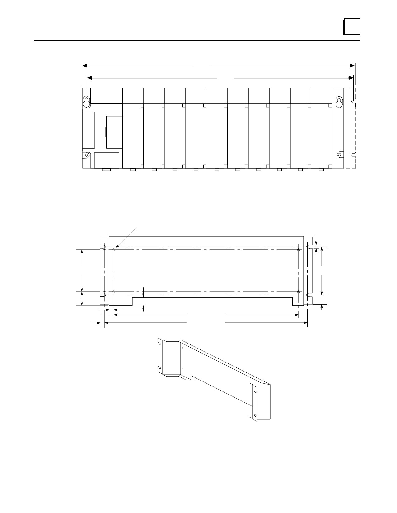
3
a45047
18.89
(480)
18.47
(469)
Î
ÎÎÎÎÎÎÎÎÎÎÎÎÎÎÎÎÎÎÎÎÎ
Î
ÎÎÎÎÎÎÎÎÎÎÎÎÎÎÎÎÎÎÎÎÎ
ÎÎÎÎÎÎÎÎÎÎÎÎÎÎÎÎÎÎÎÎÎ
ÎÎÎÎÎÎÎÎÎÎÎÎÎÎÎÎÎÎÎÎÎ
ÎÎÎÎÎÎÎÎÎÎÎÎÎÎÎÎÎÎÎÎÎ
ÎÎÎÎÎÎÎÎÎÎÎÎÎÎÎÎÎÎÎÎÎ
ÎÎÎÎÎÎÎÎÎÎÎÎÎÎÎÎÎÎÎÎÎ
DIMENSIONS IN INCHES (MILLIMETERS IN PARENTHESES)
Figure 3-19. Dimensions for 19
Rack Mounting Using IC693ACC308 Adapter Bracket
0.160 (4.06) dia. x 4
0.280
(7.1)
3.540 (90)
4.000
(101.6)
1.630
(41.4)
1.368
(34.7)
0.842
(21.4)
0.346
(8.8)
Inside
16.850 (428)
18.122
(460.3)
0.439
(11.2)
DIMENSIONS IN INCHES (MILLIMETERS IN PARENTHESES)
Figure 3-20. IC693ACC313 Recessed Mount Adapter Bracket
GFK-0356P
Chapter 3 Baseplates
3-23

3
Baseplate Comparison Table
Table 3-2. Series 90-30 Baseplate Comparison
Series 90-30 Baseplates
Catalog Number
Type
Size (Slots)
IC693CPU311
Embedded CPU
5
IC693CPU313
Embedded CPU
5
IC693CPU323
Embedded CPU
10
IC693CHS397
Modular CPU
5
IC693CHS391
Modular CPU
10
IC693CHS398
Expansion
5
IC693CHS392
Expansion
10
IC693CHS399
Remote
5
IC693CHS393
Remote
10
3-24
Series 90-30 PLC Installation and Hardware Manual - October 1999
GFK-0356P

Chapter
Power Supplies
4
Power Supply Categories
Series 90-30 power supplies are modular types that plug into the left slot of all 90-30
baseplates. They have been placed into two categories for the purpose of this chapter:
AC/DC Input Power Supplies
IC693PWR321, Standard 120/240 VAC or 125 VDC input, 30 watts total output
IC693PWR330, High Capacity 120/240 VAC or 125 VDC input, 30 watts total output
DC Input-Only Power Supplies
IC693PWR322, 24/48 VDC input, 30 watts total output
IC693PWR328 48 VDC input, 30 watts total output
IC693PWR331, High Capacity 24 VDC input, 30 watts total output
Power Supply Feature Comparison
The following table lists the features of the Series 90-30 PLC Power Supplies.
Table 4-1. Power Supply Comparison Table
Catalog
Load
Nominal
Number
Capacity
Input
Output Capacities (Voltage/Power
)
IC693PWR321
30 Watts
100 to 240 VAC or
+5 VDC
+24 VDC Isolated
+24 VDC Relay
125 VDC
15 watts
20 watts
15 watts
IC693PWR330
30 Watts
100 to 240 VAC or
+5 VDC
+24 VDC Isolated
+24 VDC Relay
125 VDC
30 watts
20 watts
15 watts
IC693PWR322
30 Watts
24 or 48 VDC
+5 VDC
+24 VDC Isolated
+24 VDC Relay
15 watts
20 watts
15 watts
IC693PWR328
30 Watts
48 VDC
+5 VDC
+24 VDC Isolated
+24 VDC Relay
15 watts
20 watts
15 watts
IC693PWR331
30 Watts
24 VDC
+5 VDC
+24 VDC Isolated
+24 VDC Relay
30 watts
20 watts
15 watts
Total of all outputs combined cannot exceed 30 watts.
4-1
GFK-0356P
4
AC/DC Input Power Supplies
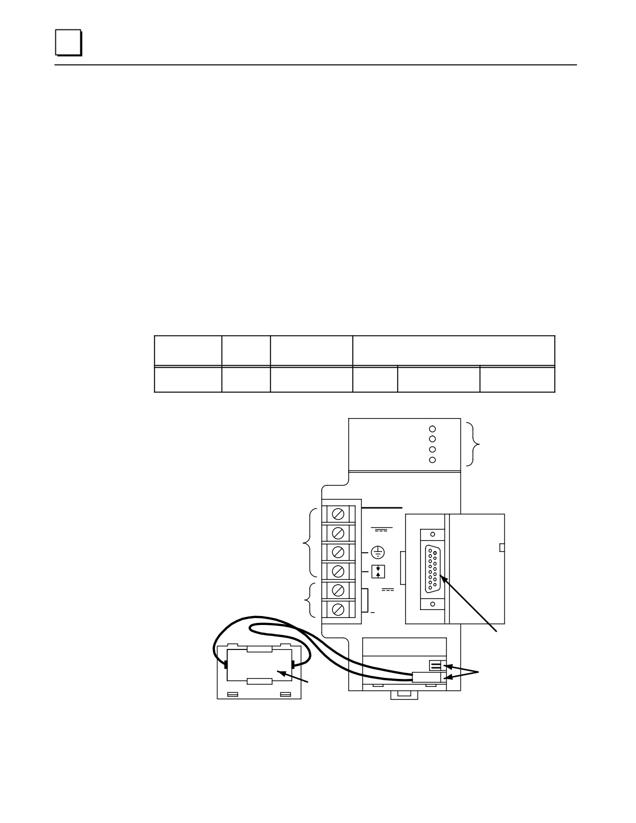
IC693PWR321 Standard Power Supply, 120/240 VAC or 125 VDC Input
The IC693PWR321 is a 30 watt supply that can operate from an input voltage source in the
range of 85 to 264 VAC or 100 to 300 VDC. This power supply provides three outputs:
+ 5 VDC output,
+ 24 VDC ”Relay” power output which provides power to circuits on Series 90-30
Output Relay modules.
“Isolated” +24 VDC, which is used internally by some modules, can also be used to
provide external power for 24 VDC Input modules.
The load capacity for each output of this power supply is shown in the following table.
Table 4-2. IC693PWR321 Power Supply Capacities
Catalog
Load
Nominal
Number
Capacity
Input
Output Capacities (Voltage/Power
)
IC693PWR321
30 Watts
100 to 240 VAC or
+5 VDC
+24 VDC Isolated
+24 VDC Relay
125 VDC
15 watts
20 watts
15 watts
Total of all outputs combined cannot exceed 30 watts.
a45613
PWR
IC693PWR321
GE Fanuc
OK
SYSTEM
STATUS
SERIES 90-30
RUN
INDICATORS
BATT
STANDARD
POWER SUPPLY
PROGRAMMABLE CONTROLLER
INPUT
100-240 VAC
∼
50/60HZ 90 VA
CONNECTIONS
125 VDC, 50W
FOR
AC/DC POWER
SOURCE
INTERNAL
POWER SOURCE
+
FOR
24 VDC
MODULES REQUIRING
OUTPUT
24VDC
0.8A MAX.
RS-485
B
COMPATIBLE
A
SERIAL PORT
T
T
E
BATTERY
R
CONNECTORS
LITHIUM
Y
BACK-UP
BATTERY
Figure 4-1. Standard AC/DC Input Power Supply - IC693PWR321
Power supplies must be installed in the leftmost slot in all baseplates.
4-2
Series 90-30 PLC Installation and Hardware Manual - October 1999
GFK-0356P

4
Note
Previous versions of this power supply had five terminals on the
terminal block. The new version (shown above), which has six
terminals, is functionally the same as the previous version. The change
was made to conform to European EC requirements.
Table 4-3. Specifications for IC693PWR321 Standard AC/DC Input Power Supply
Nominal Rated Voltage
120/240VAC or 125 VDC
Input Voltage Range
AC
85 to 264 VAC
DC
100 to 300 VDC
Input Power
90 VA with VAC Input
(Maximum with Full Load)
50 W with VDC Input
Inrush Current
4A peak, 250millisecondsmaximum
Output Power
5 VDC and 24 VDC Relay: 15 watts maximum
24 VDC Relay: 15 watts maximum
24 VDC Isolated: 20 watts maximum
NOTE: 30 watts maximum total (all three outputs)
Output Voltage
5 VDC: 5.0 VDC to 5.2 VDC (5.1 VDC nominal)
Relay 24 VDC: 24 to 28 VDC
Isolated 24 VDC: 21.5 VDC to 28 VDC
ProtectiveLimits
Overvoltage:
5 VDC output: 6.4 to 7 V
Overcurrent:
5 VDC output: 4 A maximum
Holdup Time:
20millisecondsminimum
GFK-0356P
Chapter 4 Power Supplies
4-3
4
IC693PWR330 High Capacity Power Supply, 120/240 VAC/125 VDC Input
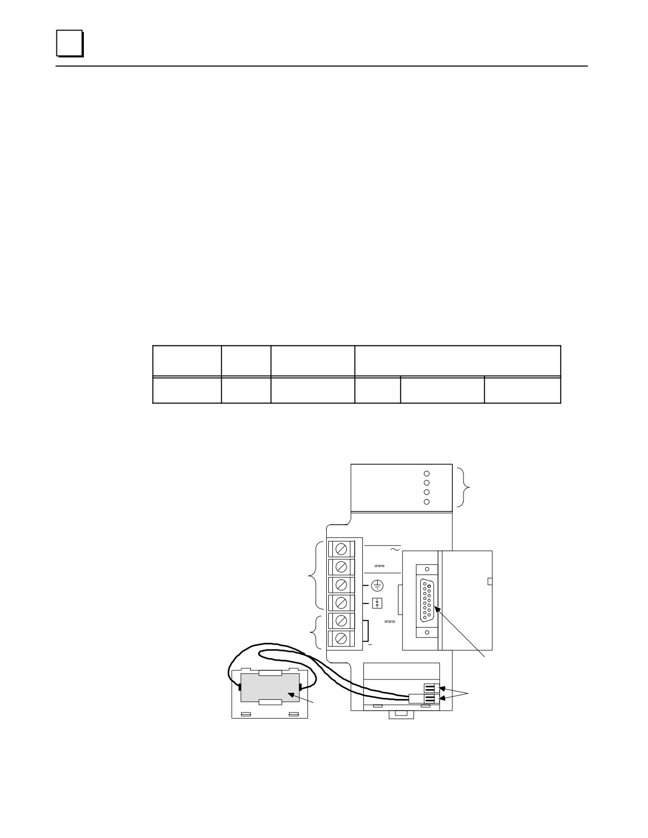
The IC693PWR330 High Capacity Power Supply is rated for 30 watts output. For
applications requiring greater +5V current capacity than is available with the standard supply
(IC693PWR321), this supply allows all 30 watts to be consumed from the +5V supply. It can
operate from an input voltage source in the range of 85 to 264 VAC or 100 to 300 VDC.
This power supply provides the following outputs:
+ 5 VDC output.
+ 24 VDC ”Relay” power output which provides power to circuits on Series 90-30
Output Relay modules.
“Isolated” +24 VDC, which is used internally by some modules, can also be used to
provide external power for 24 VDC Input modules.
The load capacity for each output of this power supply is shown in the following table.
Table 4-4. IC693PWR330 Power Supply Capacities
Catalog
Load
Nominal
Number
Capacity
Input
Output Capacities (Voltage/Power
)
IC693PWR330
30 Watts
100 to 240 VAC or
+5 VDC
+24 VDC Isolated
+24 VDC Relay
125 VDC
30 watts
20 watts
15 watts
Total of all outputs combined cannot exceed 30watts.
a45625
PWR
IC693PWR330
SYSTEM
GE Fanuc
OK
STATUS
Series 90-30
RUN
INDICATORS
BATT
HIGH CAPACITY
POWER SUPPLY
PROGRAMMABLE CONTROLLER
INPUT
100-240 VAC
50/60 HZ 100VA
ÎÎÎÎ
125VDC, 50W
CONNECTIONS FOR
ÎÎÎÎ
AC/DC POWER SOURCE
ÎÎÎÎ
ÎÎÎÎ
+
24 VDC
ÎÎÎÎ
INTERNAL POWER SOURCE FOR
OUTPUT
MODULES REQUIRING 24VDC
0.8A MAX.
ÎÎÎÎ
ÎÎÎÎ
RS-485
B
COMPATIBLE
ÎÎÎ
A
T
SERIAL PORT
T
E
BATTERY
LITHIUM
R
CONNECTORS
ÎÎÎ
Y
ÎÎÎ
BACK-UP
BATTERY
Figure 4-2. High Capacity AC/DC Input Power Supply - IC693PWR330
4-4
Series 90-30 PLC Installation and Hardware Manual - October 1999
GFK-0356P

4
Table 4-5. Specifications for IC693PWR330 High Capacity AC/DC Input Power Supply
Nominal Rated Voltage
120/240VAC or 125 VDC
Input Voltage Range
AC
85 to 264 VAC
DC
100 to 300 VDC
Input Power
100 VA with VAC Input
(Maximum with Full Load)
50 W with VDC Input
Inrush Current
4A peak, 250 ms maximum
Output Power
5 VDC: 30 watts maximum
24 VDC Relay: 15 watts maximum
24 VDC Isolated: 20 watts maximum
NOTE: 30 watts maximum total (all three outputs)
Output Voltage
5 VDC: 5.0 VDC to 5.2 VDC (5.1 VDC nominal)
24 VDC Relay: 24 to 28 VDC
24 VDC Isolated: 21.5 VDC to 28 VDC
ProtectiveLimits
Overvoltage:
5 VDC output: 6.4 to 7 V
Overcurrent:
5 VDC output: 7 A maximum
Holdup Time:
20 ms minimum
Field Wiring Connections for the AC/DC Input Power Supplies
The two AC/DC input power supplies have six terminals for user connections. These
connections are described below.
AC Power Source Connections
The Hot, Neutral, and Ground wires from the 120 VAC power source or L1, L2,
and Ground wires from the 240 VAC power source connect to the system
through the top three terminals of the terminal strip on the front of the power
supply.
DC Power Source Connections
Connect the + and - wires from the 125 VDC (nominal) power source to the
top two terminals on the terminal connector. These connections are not
polarity-sensitive on an AC/DC input power supply. (However, the DC
Input-only type supplies, which are discussed later in this chapter, are polarity
sensitive.)
Input Overvoltage Protection Devices
This information applies to all Series 90-30 power supplies except IC693PWR322
and IC693PWR328. The overvoltage protection devices for this power supply are
connected internally to pin 4 on the user terminal strip. This pin is normally
connected to frame ground (pin 3) with the supplied jumper strap which is
installed at the factory. If overvoltage protection is not required or is supplied
upstream, this feature can be disabled by removing the jumper strap from pins 3
and 4.
If you want to Hi-pot test this supply, overvoltage protection must be disabled
during the test by removing the terminal strip jumper strap. Re-enable
overvoltage protection after testing by reinstalling the strap.
GFK-0356P
Chapter 4 Power Supplies
4-5
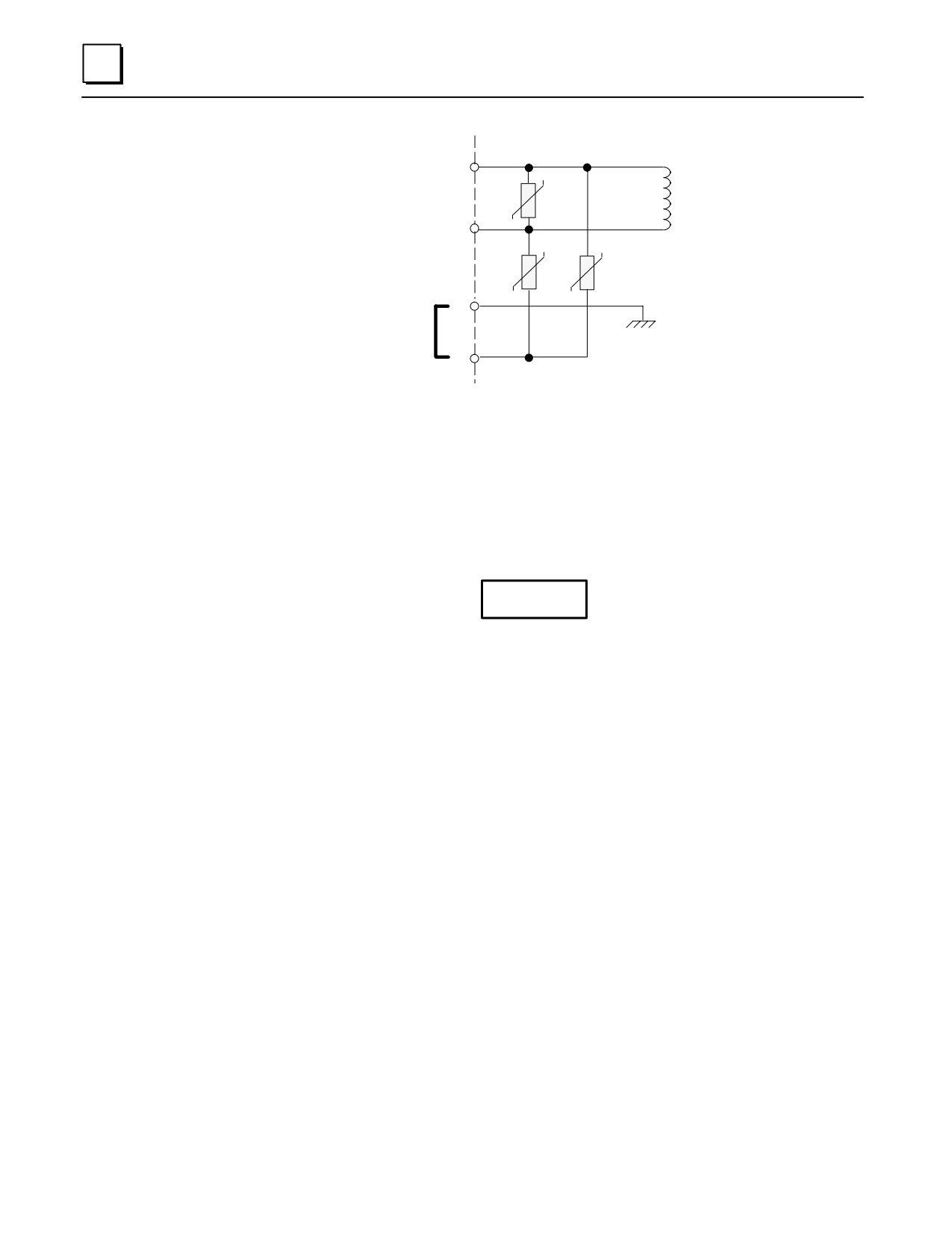
4
a47106
1
2
3
Frame Ground
Jumper Strap Connects
Overvoltage Protection
Devices to Frame Ground
4
Screw Terminals
on Terminal Board
Figure 4-3. Overvoltage Protection Devices and Jumper Strap
Isolated 24 VDC Supply Output Connections
The bottom two terminals of the power supply terminal strip provide connections
to the Isolated +24 volt DC output which can be used to provide power for
external circuits (within power limitations of the supply).
Caution
If the Isolated 24 VDC supply is overloaded or shorted, the
Programmable Logic Controller will stop operation.
4-6
Series 90-30 PLC Installation and Hardware Manual - October 1999
GFK-0356P