FANUC Series 90-30 PLC. Installation and Hardware Manual (GFK-0356P) - page 2
1
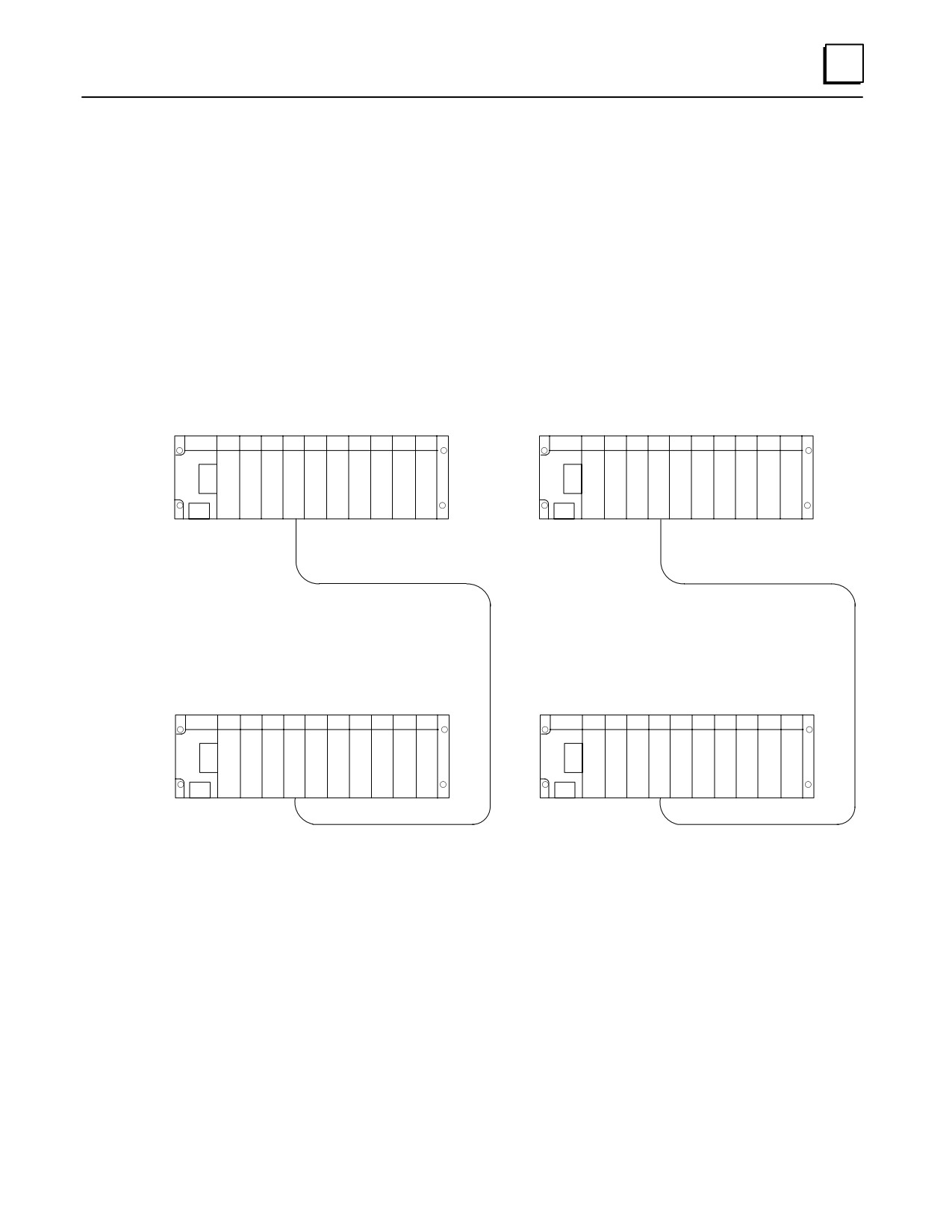
What if I need to cover more than 700 feet (213 meters) ?
You can cover much greater distances by using Series 90-30 communications option
modules. For example, Genius Bus Controller Modules (GBC) can communicate at
distances up to 7,500 feet (2,286 meters) over a shielded twisted-pair cable, as shown in
Example 1 below. Or, serial communications with Communications Coprocessor
Modules (CMM) using the RS-485 standard can cover up to 4,000 feet (1,219 meters), as
shown in Example 2 below. And virtually unlimited communication distances can be
attained with modems and telephone lines or radio transmitters. Also, there are
numerous networking options available such as Ethernet or WorldFIP.
Example 1 - GBC
Example 2 - CMM
Series 90-30 PLC
Series 90-30 PLC
CPU
GBC
CPU
CMM
Shielded, Twisted-Pair Cable, 7,500
Serial Cable, 4,000 Feet (1,219
Feet (2,286 Meters) Maximum Length
Meters) Maximum Length
Series 90-30 PLC
Series 90-30 PLC
CPU
GBC
CPU
CMM
Figure 1-10. Connecting PLCs Using GBC or CMM Modules
GFK-0356P
Chapter 1 Overview of the Series 90-30 PLC
1-9
Chapter
Installation
2
This chapter discusses installation details only. Other information about the products
such as hardware descriptions and specifications, are covered in the applicable chapter.
- Important Note -
The installation instructions described in this chapter apply to PLC installations
that do not require special procedures for noisy or hazardous environments. For
installations that must conform to more stringent requirements (such as CE
Mark), see GFK-1179, Installation Requirements for Conformance to
Standards. Also see GFK-0867, GE Fanuc Product Agency Approvals,
Standards,GeneralSpecifications.
Receiving your Products - Visual Inspection
When you receive your Series 90-30 PLC system, carefully inspect all shipping containers
for damage that may have occurred during shipping. If any part of the system is
damaged, notify the carrier immediately. The damaged shipping container should be
saved as evidence for inspection by the carrier.
As the consignee, it is your responsibility to register a claim with the carrier for damage
that happened during shipment. However, GE Fanuc will fully cooperate with you if
such action is necessary.
Pre-installation Check
After unpacking Series 90-30 PLC racks, cables, modules, etc., record all serial numbers.
Serial numbers are printed on the module packaging. Serial numbers are required to make a
claim during the warranty period of the equipment. All software product registration cards
should be completed and returned to GE Fanuc. See the “Module Features” section in this
chapter for location of module serial numbers. See the “Common Baseplate Features”
section in the “Baseplates” chapter for location of baseplate serial numbers.
You should verify that all components of the system have been received and that they
agree with your order. If the parts received do not agree with your order, call
Programmable Control Customer Service, toll free, in Charlottesville, VA at
1-800-432-7521. A Customer Service representative will provide further instructions.
If you require assistance with your installation, the GE Fanuc Technical Service Hotline
personnel in Charlottesville, VA are available to help you. North American customers
should call toll-free at 1-800-GE FANUC (1-800-433-2682). International customers
should dial direct: 804-978-6036. The GE Fanuc web site support address is
www.gefanuc.com/support/plc. Chapter 13, “Maintenance and Troubleshooting” has
additional telephone numbers and troubleshooting information.
Warranty Claims
Record the serial number of the defective item and contact your distributor for
instructions.
2-1
GFK-0356P
2
Working with Series 90-30 Modules
Module Features
1
13
7
8
12
2
11
IC693CPUXXX
3
CPU MODULE
25 MHZ
LISTED
xxxxxxx
4
123456789
10
14
1234567
5
2
6
6
7
8
9
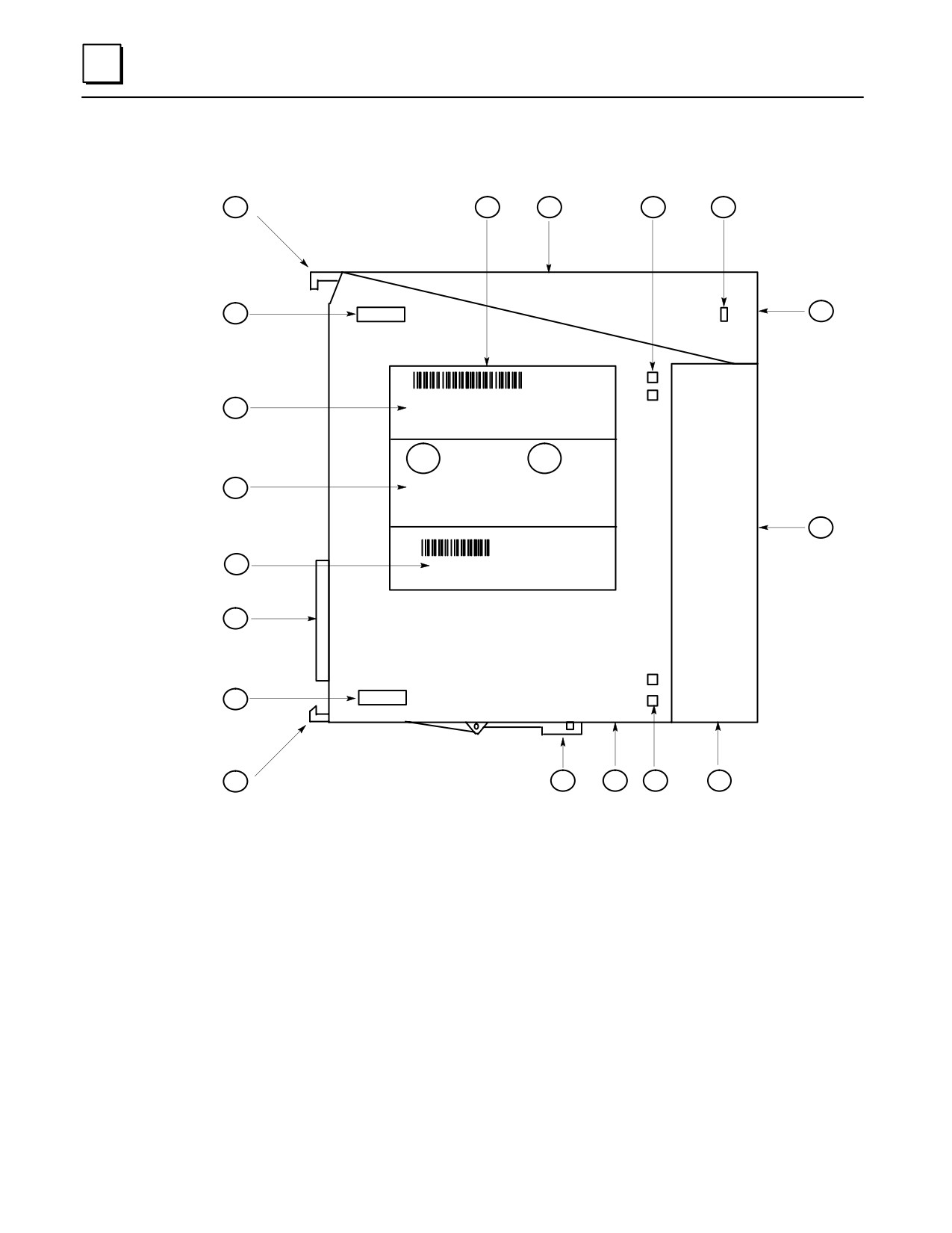
Figure 2-1. Features of Series 90-30 Module
1.
Pivot hook
2.
Circuit board holding tabs (two on each side of module)
3.
Catalog number and description section of label
4.
Certification (UL, CE, etc.) section of label
5.
Module connector - plugs into baseplate backplane connector
6.
Release lever - spring loaded
7.
Ventilation openings in module case (top and bottom)
8.
Front cover holding tabs (two on each side of module)
9.
Front cover (shown) or terminal board (for I/O modules).
10. Front cover faceplate or hinged cover for terminal board.
11. Lens cap (some modules do not have).
12. Lens cap holding tabs (one on each side of module)
13. Module label
14. Serial Number - used to determine module warranty status. Note that on some
modules, the Serial Number may be on a small tag on the back of the module.
2-2
Series 90-30 PLC Installation and Hardware Manual - October 1999
GFK-0356P
2
Installing a Module
Warning
Do not insert or remove modules with power applied. This could
cause the PLC to stop or malfunction. Injury to personnel and damage
to the module or baseplate may result. Also, attempts to force a
module into an improper slot type will result in damage to the module
and/or the baseplate. Modules will mount in the correct slot type
easily, with a minimum of force.
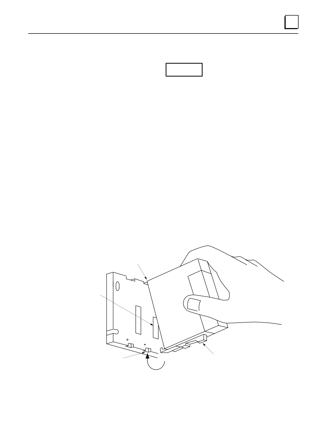
Use the following instructions as a guide when inserting a module into a baseplate slot.
Check that module catalog number matches slot configuration. Each slot is, or will
be, assigned a particular module type during configuration. A Power Supply
module must be installed in the left end unnumbered slot only, and a CPU module
and some special Option modules can only be installed in Slot 1 of a CPU baseplate.
I/O Modules and most Option modules install in slots numbered 2 and higher.
Grasp the module firmly with terminal board toward you and with rear pivot hook
facing away from you.
Align the module with the desired baseplate slot and connector. Tilt the module
upwards so that top rear pivot hook of the module engages the baseplate’s top
module retainer.
Swing the module downward until the module’s connector engages the baseplate’s
backplane connector, and the release lever on the bottom of the module snaps into
place in the baseplate’s bottom module retainer.
Visually inspect the module to be sure that it it properly seated.
a43055A
PIVOT HOOK
BACKPLANE
CONNECTOR
RELEASE LEVER
BOTTOM RETAINER
Figure 2-2. Installing a Module
GFK-0356P
Chapter 2 Installation
2-3
2
Removing a Module
Warning
Do not insert or remove modules with power applied. This could
cause the PLC to stop or malfunction. Injury to personnel and damage
to the module or baseplate may result. Also potentially dangerous
voltages from user devices may be present on a module’s screw
terminals even though power to the rack is turned off. Care must be
taken any time that you are handling the module’s removable terminal
board or any wires connected to it.
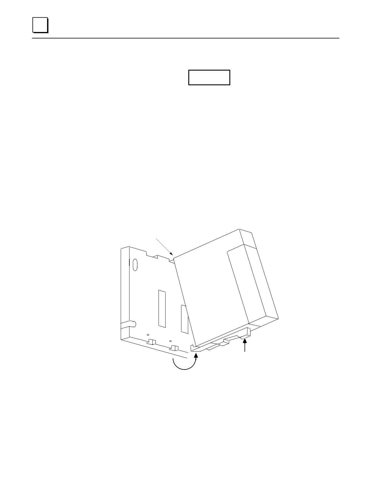
If the module has wiring, remove the module’s terminal board (NOTE: You do not
have to unwire the terminal board) or cables. The procedure for removing a
terminal board is described later in this section.
Locate the release lever at the bottom of the module and firmly press it up, towards
the module.
While holding the module firmly at its top and fully depressing release lever, swing
(pivot) the module upward (release lever must be free of its retaining slot).
Disengage pivot hook at the top rear of the module by moving the module up and
away from the baseplate.
a43056
PIVOT HOOK
ÎÎ
Î
Î
PRESS
RELEASE LEVER
Figure 2-3. Removing a Module
Note
Modules in expansion or remote baseplates can be added, removed, or
replaced while the PLC is in RUN mode if power is first removed from
the expansion or remote baseplate. I/O data to/from this baseplate will
not be updated while power is removed.
2-4
Series 90-30 PLC Installation and Hardware Manual - October 1999
GFK-0356P
2
Installing a Module’s Terminal Board
Note: Modules IC693MDL730F (and later) and IC693MDL731F (and later) have special
terminal boards that are equipped with holding screws. For Installation and Removal
instructions, please see the section “Installing and Removing Terminal Boards with
Holding Screws” later in this chapter.
To install a terminal board:
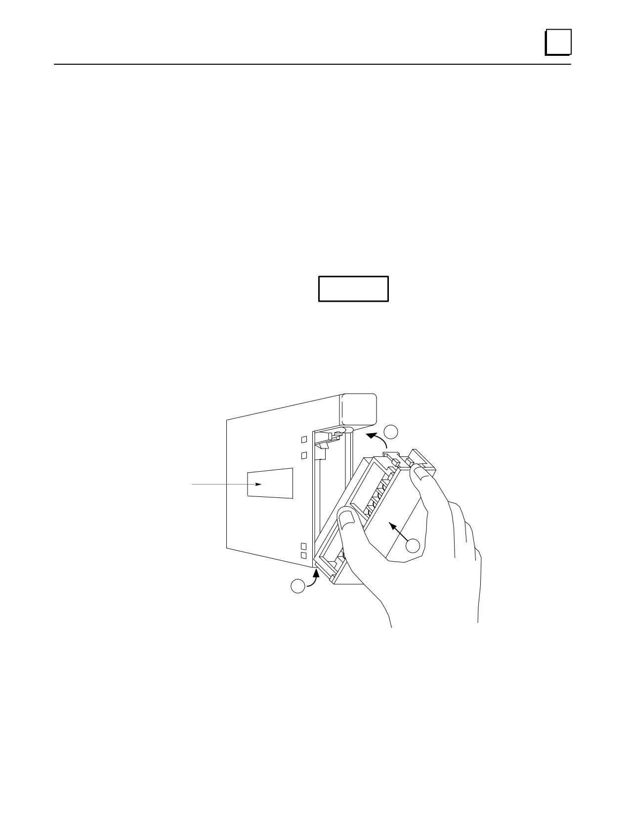
Hook the pivot hook➀, located on the bottom of the terminal board, to the lower
slot on the module.
Push the terminal board towards the module➁ until it snaps into place.
Open the terminal board cover➂ and ensure that the latch on the module is
securely holding the terminal board in place.
Caution
Compare the module catalog number on the label on the back of the hinged
door (see Figure 2-6) and the label on the side of the module (see below) to
ensure that they match. If a wired terminal board is installed on the wrong
module type, damage to the module may occur when the system is powered
up.
a43062
2
Module
Label
3
1
REFER TO TEXT FOR
INSTALLATION PROCEDURE
Figure 2-4. Installing an I/O Module’s Terminal Board
GFK-0356P
Chapter 2 Installation
2-5
2
Removing a Module’s Terminal Board
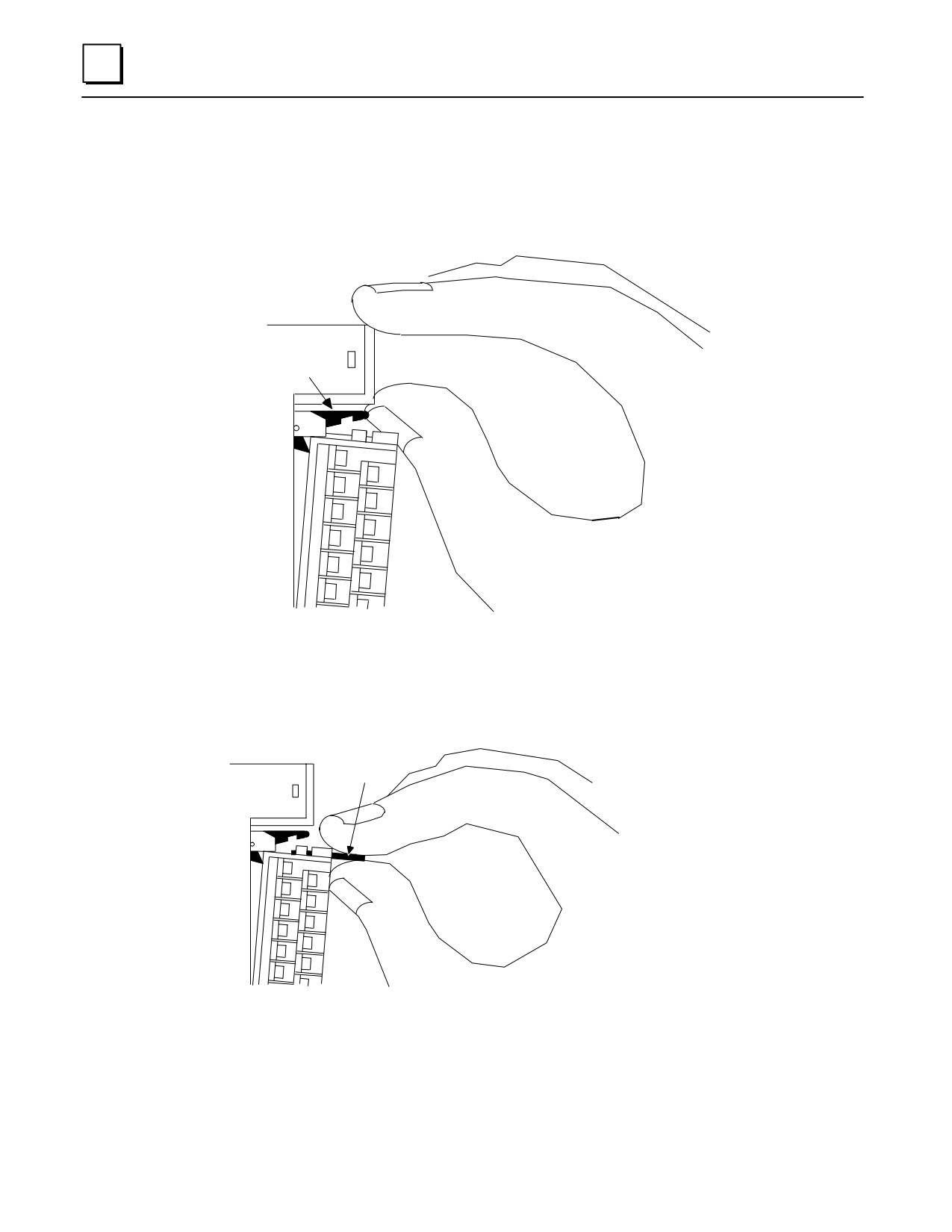
To remove a terminal board:
Open the plastic terminal board cover.
Push up on the jacking lever to release the terminal block.
a43061
ÎÎÎ
ÎÎÎ
JACKING
LEVER
Î
ÎÎÎ
ÎÎÎ
Grasp pull-tab and pull it towards you until contacts have separated from module
housing and bottom pivot hook has disengaged.
a43715
PULL
TAB
ÎÎÎ
ÎÎÎ
Figure 2-5. Removing a Module’s Terminal Board
2-6
Series 90-30 PLC Installation and Hardware Manual - October 1999
GFK-0356P
2
I/O Module Terminal Board Posts
Notice that the terminal board has three posts on the left side. The top and bottom posts
hold the terminal board cover in place. The purpose of the middle post is to keep the
terminal board wiring in place. This middle post can be easily snapped off if you do not
require it to hold the wiring in place.
Since minimal force is required to snap off the middle post, you should be careful that
you do not inadvertently snap it off if you are using it to keep your wiring in place.
Installing and Removing Terminal Boards with Holding Screws
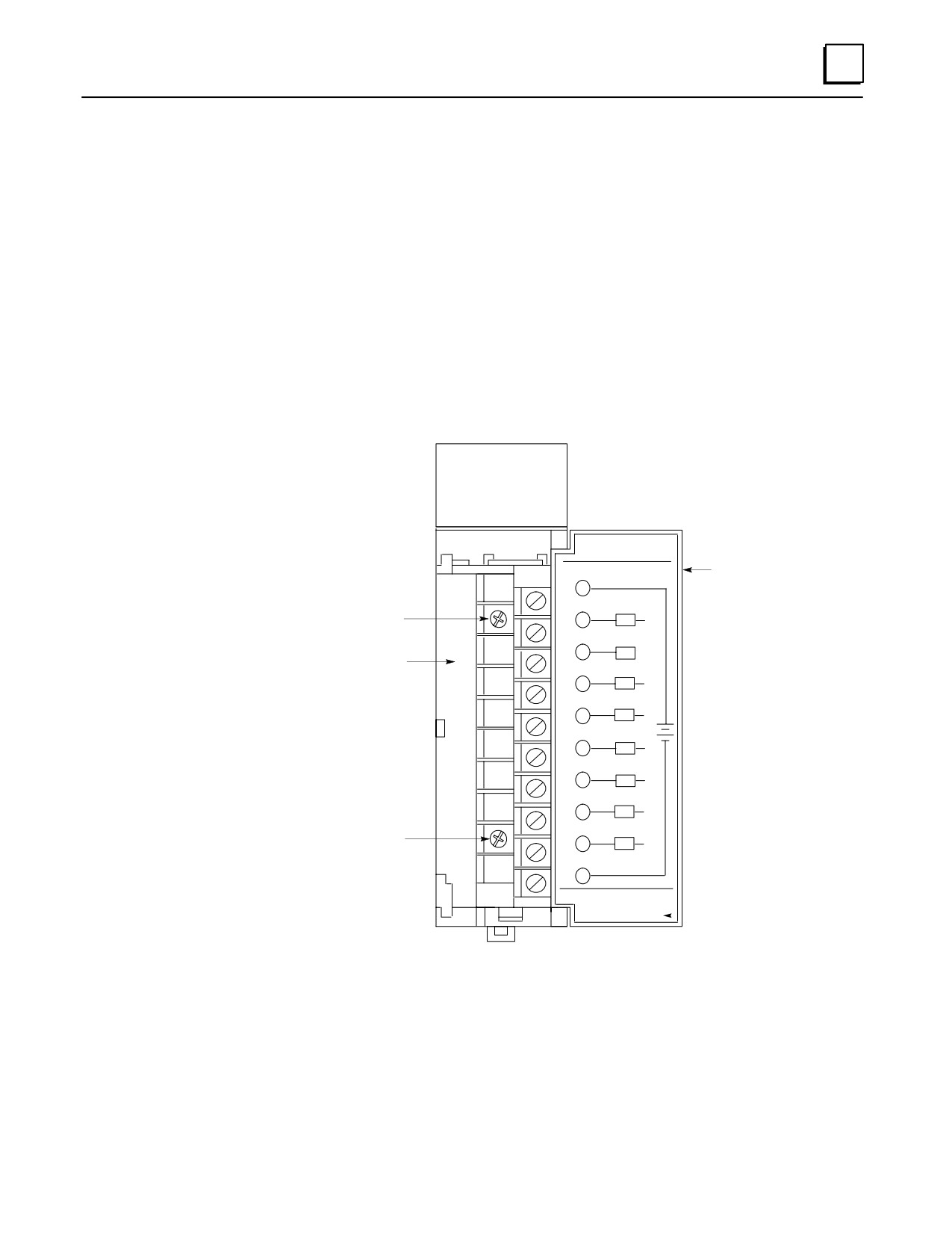
Discrete output modules IC693MDL730F (and later) and IC693MDL731F (and later)
have a special terminal board that is equipped with holding screws, shown in the figure
below. These screws prevent the terminal board-to-module connections from
deteriorating in applications where the PLC is subjected to severe vibration .
a43082B
A1 2 3 4 5 6 7 8
F
B1 2 3 4 5 6 7 8
ÎÎÎÎÎÎ
ÎÎÎÎÎÎÎ
Hinged Cover
ÎÎÎÎÎÎÎ
2
ÎÎÎÎÎÎÎ
Holding Screw
4
ÎÎÎÎA1ÎÎÎ
6
ÎÎÎÎÎÎÎ
A2
Removeable Terminal Board
ÎÎÎÎÎÎÎ
ÎÎ8ÎÎA3ÎÎÎ
ÎÎ10ÎÎA4Î+ÎÎ
ÎÎÎÎΖÎÎ
12
A5
ÎÎÎÎÎÎÎ
ÎÎ14ÎÎA6ÎÎÎ
ÎÎ16ÎÎA7ÎÎÎ
Holding Screw
ÎÎÎÎÎÎÎ
18
A8
ÎÎÎÎÎÎÎ
ÎÎ20ÎÎÎÎÎ
ÎÎÎÎÎÎÎ
IC693MDL730F
Module Catalog Number
ÎÎÎÎÎÎ
Figure 2-6. Terminal Board with Holding Screws
Removing: To Remove these terminal boards, first loosen the two holding screws on
the front of the terminal board, then follow the standard removal instructions in the
section “Removing an I/O Module’s Terminal Board.” The holding screws are held
captive in the terminal board and do not have to be completely removed.
Installing: To install these terminal boards, follow the standard installation
instructions in the section “Installing an I/O Module’s Terminal Board,” then tighten
the two holding screws to 8 to 10 inch pounds (1 Newton-meter) of torque.
GFK-0356P
Chapter 2 Installation
2-7
2
Baseplate Mounting
Warning
Be sure to follow baseplate grounding instructions in this chapter.
Failure to properly ground the PLC can result in improper operation,
damage to equipment, and injury to personnel.
Mounting a Baseplate to a Panel
Use four good-quality 8-32 x 1/2 (4 x 12 mm) machine screws, lock washers and flat
washers. Install the screws in four 8-32 tapped holes. The “Baseplates” chapter has
the applicable dimensions and mounting clearances. Alternately, 10-slot baseplates
can be mounted in standard 19-inch racks by using the appropriate adapter. This is
also discussed in the “Baseplates” chapter.
A vertical mounting orientation is preferred for maximum heat dissipation. Other
mounting orientations will require derating the Power Supply current capabilities.
See Chapter 12, “System Design,” for details.
All baseplates must be grounded. The “Baseplate Safety Grounding” section of this
chapter has details.
The Rack Number Selection switch must be set on each Expansion or Remote
baseplate. A CPU baseplate does not require this switch. Rack numbers should be
assigned by the system designer. Failure to set the Rack Number Selection switches
properly will result in system malfunction. See the “Baseplates” chapter for details
on setting these switches.
Mounting a Baseplate to a 19” Rack
Two optional Baseplate Adapter Brackets allow a 10-slot baseplate to be mounted in a 19
inch rack. Each baseplate installation requires only one of the adapter brackets.
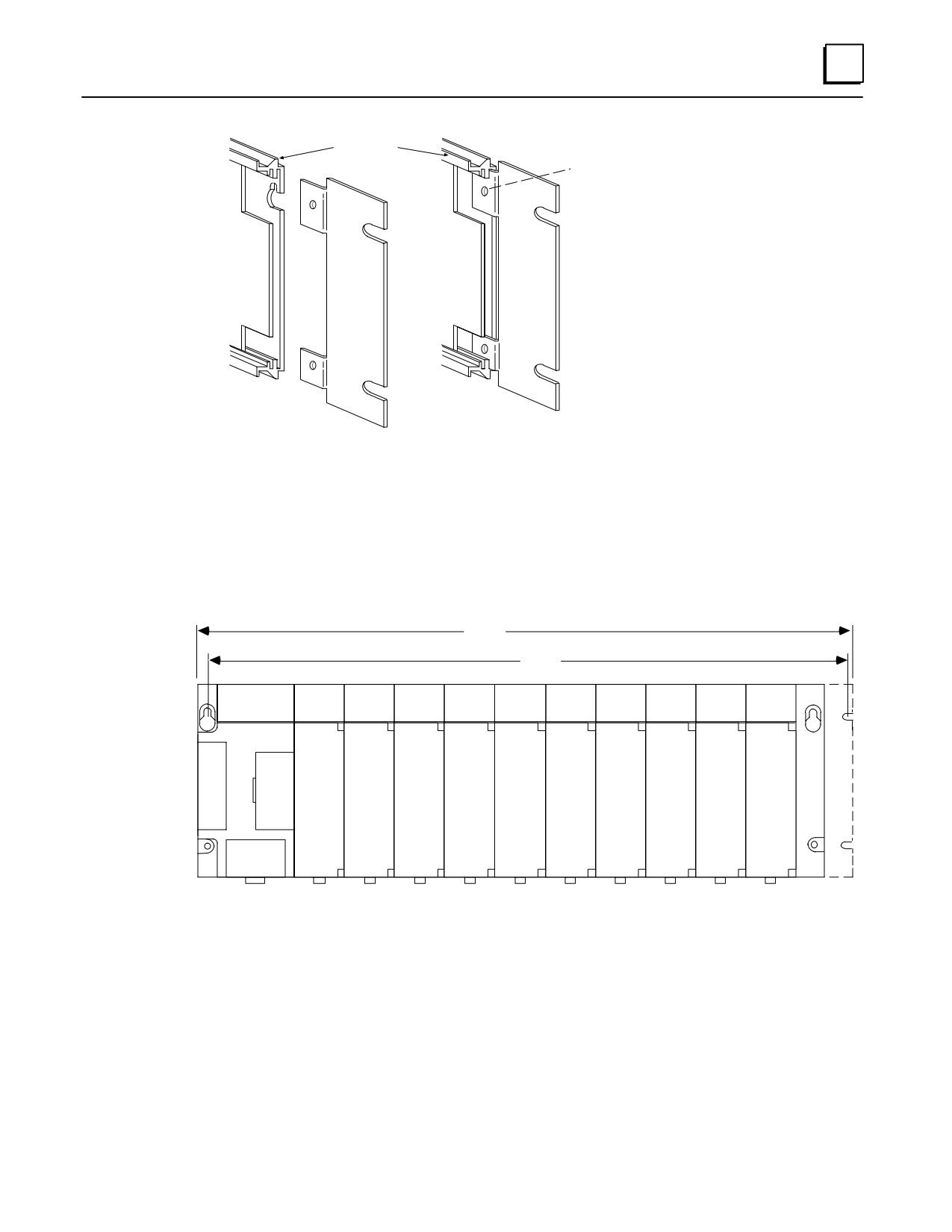
IC693ACC308 Front Mount Adapter Bracket. Used to mount a baseplate to the
front face of a 19” rack. Install the adapter bracket by inserting the tabs at the top
and bottom of the adapter bracket into the corresponding slots at the top and
bottom of the plastic baseplate cover. NOTE: Although the figure below shows the
plastic baseplate cover removed, this is for illustration purposes only. It is not
necessary to remove the cover to install the bracket. With the bracket in place, insert
and tighten the two screws (included with the bracket) through the back of the
baseplate holes into the threaded holes in the bracket.
IC693ACC313 Recessed Mount Adapter Bracket. Used to recess mount a baseplate
inside a 19” rack. A baseplate mounts on the rear panel of this adapter bracket using
four 8-32 (4 mm) screws, nuts, lockwashers and flat washers. The Adapter Bracket
bolts through its four slotted holes to the face of the 19” rack using applicable
hardware (lockwashers recommended).
2-8
Series 90-30 PLC Installation and Hardware Manual - October 1999
GFK-0356P
2
RIGHT SIDE OF
a43726A
BASEPLATE
Insert two screws (1 at top; 1 at bottom)
from back of base unit through base unit
and bracket. Tighten screws to secure
bracket to base unit.
Note: Baseplate is shown with cover removed for illustration purposes. It
is not necessary to remove the baseplate cover to install the bracket.
Figure 2-7. IC693ACC308 Front Mount Adapter Bracket Installation
Dimensions for rack mounting a 10-slot baseplate with the IC693ACC308 Front Mount
Adapter Bracket are shown in the following figure.
a45047
18.89
(480)
18.47
(469)
ÎÎÎÎÎÎÎÎÎÎÎÎÎÎÎÎÎÎÎÎÎ
Î
ÎÎÎÎÎÎÎÎÎÎÎÎÎÎÎÎÎÎÎÎÎ
ÎÎÎÎÎÎÎÎÎÎÎÎÎÎÎÎÎÎÎÎÎ
ÎÎÎÎÎÎÎÎÎÎÎÎÎÎÎÎÎÎÎÎÎ
ÎÎÎÎÎÎÎÎÎÎÎÎÎÎÎÎÎÎÎÎÎ
ÎÎÎÎÎÎÎÎÎÎÎÎÎÎÎÎÎÎÎÎÎ
ÎÎÎÎÎÎÎÎÎÎÎÎÎÎÎÎÎÎÎÎÎ
ÎÎÎÎÎÎÎÎÎÎÎÎÎÎÎÎÎÎÎÎÎ
DIMENSIONS IN INCHES (MILLIMETERS IN PARENTHESES)
Figure 2-8. Dimensions for 19
Rack Mounting Using IC693ACC308 Adapter Bracket
GFK-0356P
Chapter 2 Installation
2-9
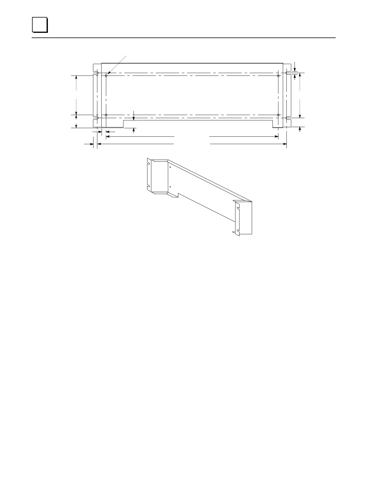
2
0.160 (4.06) dia. x 4
0.280
(7.1)
3.540 (90)
4.000
(101.6)
1.630
(41.4)
1.368
(34.7)
0.842
(21.4)
0.346
(8.8)
Inside
16.850 (428)
18.122
(460.3)
0.439
(11.2)
DIMENSIONS IN INCHES (MILLIMETERS IN PARENTHESES)
Figure 2-9. IC693ACC313 Recessed Mount Adapter Bracket
2-10
Series 90-30 PLC Installation and Hardware Manual - October 1999
GFK-0356P
2
Grounding Procedures
System Grounding Procedures
Warning
In addition to the following grounding information, we strongly urge
that you follow all applicable codes that apply to your area. For
example, in the United States, most areas have adopted the National
Electrical Code standard and specify that all wiring conform to its
requirements. In other countries, different codes will apply. For
maximum safety to personnel and property you must follow these
codes. Failure to do so can mean injury or death to personnel, damage
to property, or both.
All components of a programmable logic control system and the devices it is controlling
must be properly grounded. This is particularly important for the following reasons.
A low resistance path from all parts of a system to earth minimizes exposure to
shock in the event of short circuits or equipment malfunction.
The Series 90-30 PLC system requires proper grounding for correct operation.
The importance of a proper grounding cannot be over-emphasized.
Ground Conductors
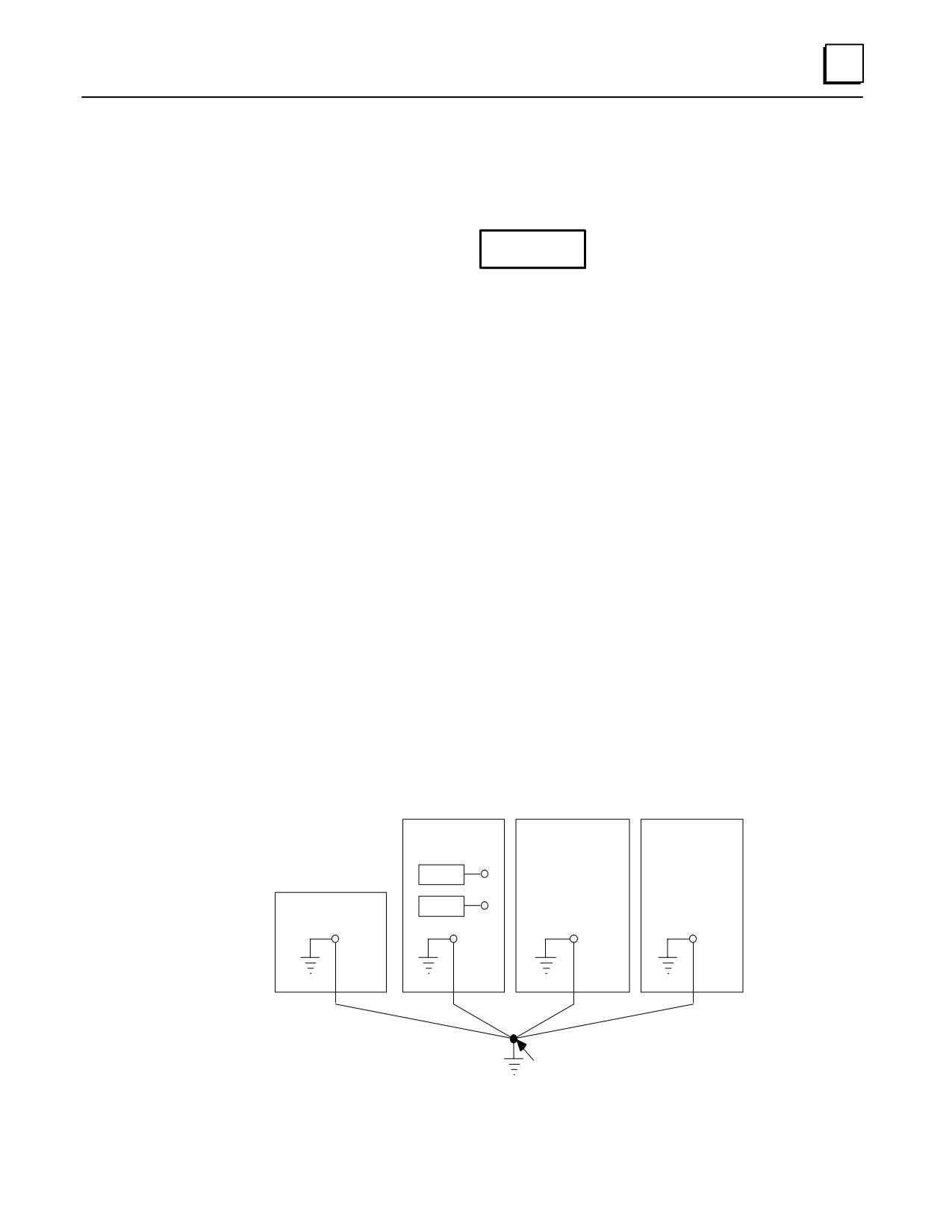
Ground conductors should be connected in a tree fashion with branches routed to a
central earth ground point, shown in the figure below. This ensures that no ground
conductor carries current from any other branch. This method is shown in the
following figure.
Ground conductors should be as short and as large in size as possible. Braided
straps or ground cables (typically green insulation with a yellow tracer - AWG #12
(3.3 mm2) or larger) can be used to minimize resistance. Conductors must always be
large enough to carry the maximum short circuit current of the path being
considered.
a43059
SERIES 90-30
MOTOR DRIVES
MACHINERY
PLC CABINET
AND OTHER
ELECTRICAL
RACK
CONTROL
EQUIPMENT
PROGRAMMING
RACK
DEVICE
NOTE
SIGNAL AND POWER
EARTH
CENTRAL
CONNECTIONS
GROUND
GROUND POINT
ARE NOT SHOWN
Figure 2-10. Recommended System Grounding
GFK-0356P
Chapter 2 Installation
2-11
2
Series 90-30 PLC Equipment Grounding
Equipment grounding recommendations and procedures are listed below. These
grounding procedures must be properly followed for safe, proper operation of your Series
90-30 PLC system.
Baseplate Safety Grounding
The following recommendations are offered, but applicable safety codes for your area or
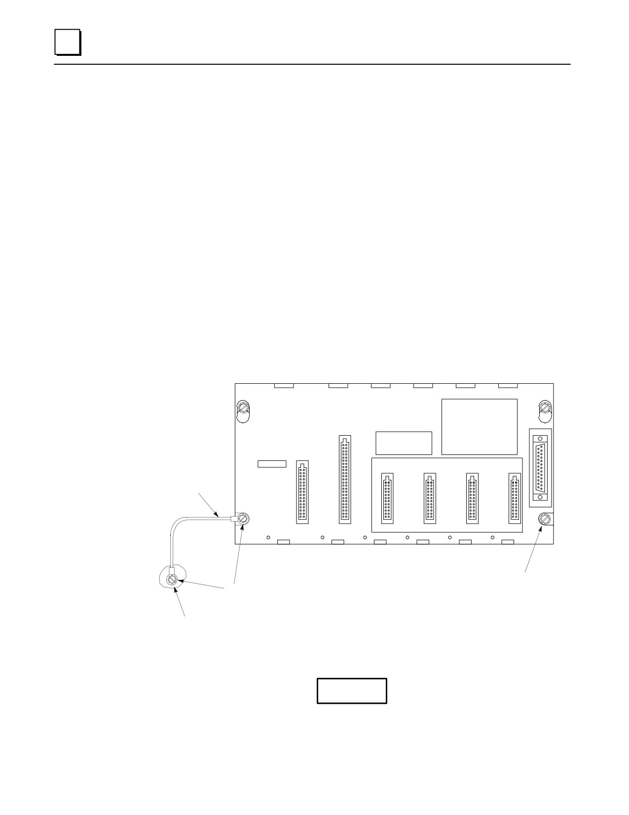
equipment type should also be consulted. The baseplate’s metal back must be grounded
using a separate conductor; the baseplate mounting screws are not considered to an
acceptable ground connection by themselves. Use a minimum AWG #12 (3.3 mm2) wire
with a ring terminal and star lock washer under the head of one of the baseplate’s two
lower mounting holes. These two holes have openings to the side to allow connecting a
wire and ring terminal under the head of a mounting screw. Connect the other end of this
ground wire to a tapped hole in the panel that the baseplate is mounted to, using a machine
screw, star lock washer, and flat washer. Alternately, if your panel has a ground stud, it is
recommended you use a nut and star lock washer for each wire on the ground stud to
ensure adequate grounding. Where connections are made to a painted panel, the paint
should be removed so clean, bare metal is exposed at the connection point. Terminals and
hardware used should be rated to work with the aluminum baseplate material.
PROGRAMMABLE
CONTROLLER
BASE 5-SLOT
E
X
P
A
CAUTION
NON-CPU SLOTS
N
USER PROGRAM
S
AND REGISTER
I
AWG #12 or
VALUES MAY BE
LOST IF POWER
O
Larger Wire
SUPPLY IS
N
REMOVED FOR
LONGER THAN
1 HOUR
CPU/1
I/O-2
I/O-3
I/O-4
I/O-5
POWER
SUPPLY
Alternate location
for Ground connection
Screw, Star Lock washer,
Flat Washer, Ring Terminal,
installed in tapped hole.
Paint Removed
From Panel Here
Figure 2-11. Baseplate Grounding
Warning
All baseplates must be grounded to minimize electrical shock hazard.
Failure to do so can result in severe personal injury.
2-12
Series 90-30 PLC Installation and Hardware Manual - October 1999
GFK-0356P
2
All baseplates grouped together in a Series 90-30 PLC system must have a common ground
connection. This is especially important for baseplates that are not mounted in the same
control cabinet.
Grounding 19” Rack-Mounted Baseplates
There are two Adapter Brackets used for mounting a 10-slot Series 90-30 baseplate to a
19” Rack. Regardless of which of the two Adapter Brackets is used, the 19” Rack should
be grounded as per the instructions in “System Grounding Procedures,” including Figure
2-10. (For details on the Adapter Brackets, see the “Mounting a Baseplate to a 19” Rack”
section earlier in this chapter.)
Nineteen-Inch Rack-mounted PLC baseplates should be grounded according to the
guidelines in the “Baseplate Safety Grounding” section, using a separate ground wire
from the PLC baseplate as shown in the previous figure (Fig. 2-11).
If using the Recessed Mount Adapter Bracket (IC693ACC313), the ground wire can
be installed as shown in Figure 2-11 with the ground attached to the Recessed
Mount Adapter Bracket. An additional ground wire connecting the Adapter Bracket
to a solid chassis ground on the 19” Rack should be installed. Use the same or
equivalent hardware and paint removal scheme as shown in Figure 2-11.
If using the Surface Mount Adapter Bracket (IC693ACC308), the ground wire
should be run from the baseplate as shown in Figure 2-11, to a solid chassis ground
on the 19” Rack. Use the same or equivalent hardware and paint removal scheme as
shown in Figure 2-11.
Programmer Grounding
For proper operation, the computer (programmer) running the PLC software must have
a ground connection in common with the CPU baseplate. Normally, this common
ground connection is provided by ensuring that the programmer ’s power cord is
connected to the same power source (with the same ground reference point) as the
baseplate. If it is not possible to ensure this common ground scheme, use a port isolator
(IC690ACC903) between the programmer and PLC serial connection. If the programmer
ground is at a different potential than the PLC ground, a shock hazard could exist. Also,
damage to the ports or converter (if used) could occur when the programmer serial cable
is connected between the two.
Warning
Failure to follow programmer grounding recommendations could
result in personal injury, equipment damage, or both.
GFK-0356P
Chapter 2 Installation
2-13
2
Module Shield Grounding
In general, the aluminum PLC baseplate is used for module shield grounding. On some
Series 90-30 modules, shield connections to the user terminal connector on the module
are routed to the baseplate through the module’s backplane connector. Other modules,
such as CPUs 351, 352, 363, and 364, require a separate shield ground. These are
discussed in the next several sections.
Shield Grounding Information for CPUs with External Port Connections
CPUs with external port connections, the 351, 352, 363, and 364, must have a separate
shield ground connection which provides shielding for these ports. The design of the
ground connection for the CPU351 and 352 is different from that of the CPU363 and 364,
so each grounding method is discussed in a separate heading.
CPU351 and 352 Shield Grounding
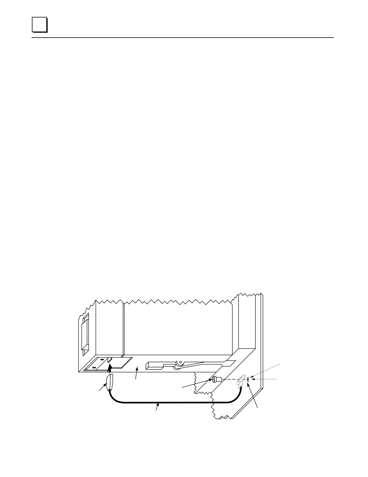
The CPU 351 or 352 module must be connected to frame ground at the slot where it is
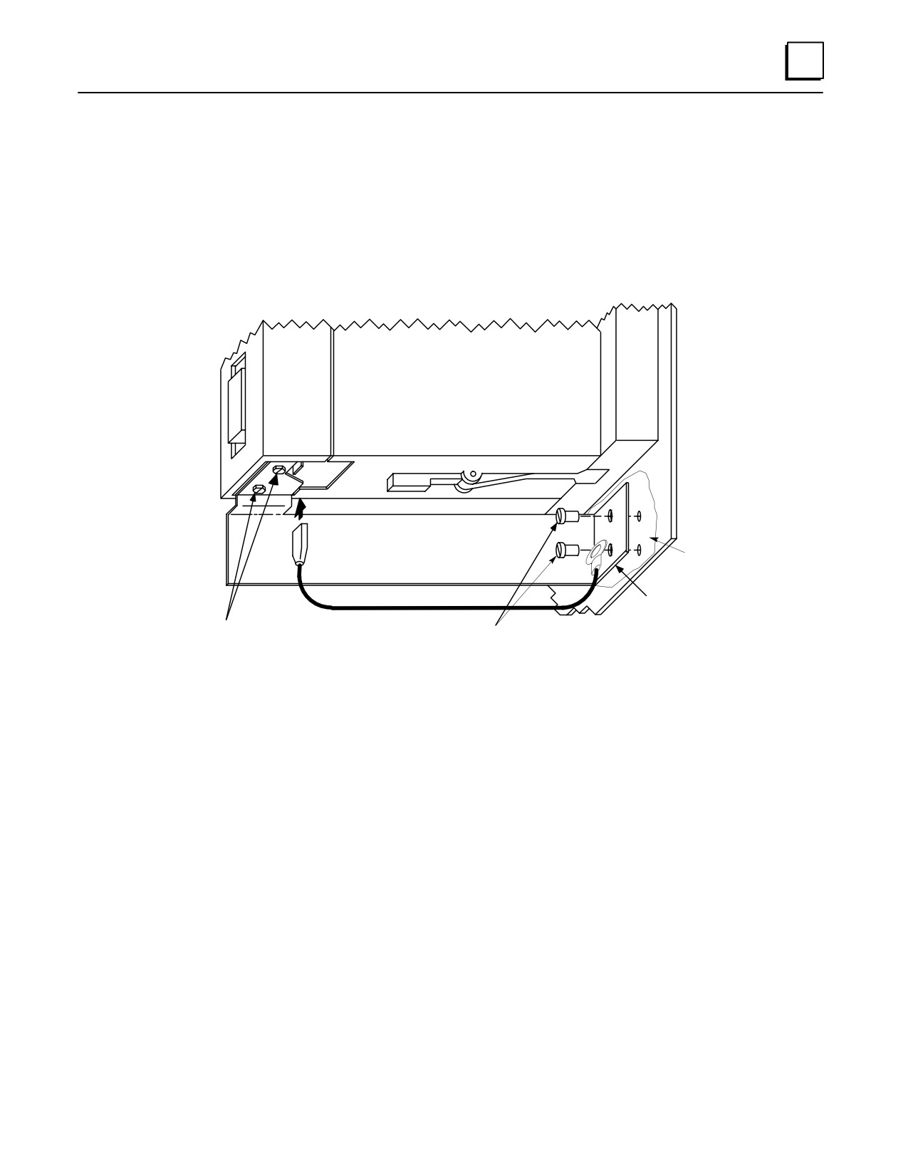
installed. Two methods are provided for making this ground connection. Each CPU
comes with an EMC Grounding Kit (44A737591-G01) that contains a ground wire,
grounding bracket, and screws.
1.
The connection from the CPU to frame ground can be made using the ground wire
(part number 44A735970-001R01) that comes with the module in the EMC
Grounding Kit. This wire has a stab-on connector on one end for connection to a
mating terminal on the bottom of the CPU, and a ring terminal on the other end for
connection to a grounded enclosure. Where the ring terminal contacts a painted
enclosure panel, either a star lock washer can be installed between the terminal and
the panel to cut through the paint, or the paint can be scraped away down to clean,
bare metal to ensure a good contact. Note: The star lock washer method is
suitable for a shield ground, but not suitable for a safety ground.
CPU351 or 352
#6 TAPPED HOLE
REMOVE PAINT UNDER
BOTTOM OF
RING TERMINAL OR INSTALL
CPU MODULE
USE 1 #6
STAR LOCK WASHER BETWEEN
MACHINE SCREW
TERMINAL AND PANEL
STAB-ON
CONNECTOR
MOUNT ON
44A735970-001R01
GROUNDED
ENCLOSURE
Figure 2-12. CPU 351 or 352 - Attaching Ground Wire
2-14
Series 90-30 PLC Installation and Hardware Manual - October 1999
GFK-0356P
2
2.
The second method, which can be used for systems in noisy environments consists
of installing the green ground wire and the optional grounding bracket (part
number 44C715646-001R01). This bracket attaches to the CPU using two #4
thread-rolling screws (part number N666P9004B6) and to the grounded enclosure
using two #6 thread-rolling screws (part number N666P13006B6). Two holes must
be drilled in the enclosure for mounting this bracket. Also, if the bracket will be
attached to a painted surface, the paint should be removed down to bare metal
under the bracket to ensure good contact between the bracket and the surface. See
the next figure.
a45514A
CPU351 or 352
44C715646-001R01
PAINT REMOVED WHERE
BRACKET
BRACKET MOUNTS TO PANEL
MOUNT ON
GROUNDED
ENCLOSURE
USE 2 #4
USE 2 #6
THREAD ROLLING SCREWS
THREAD ROLLING SCREWS
(N666P9004B6)
(N666P13006B6
Figure 2-13. CPU 351 or 352 - Mounting Grounding Bracket
Note: When the grounding bracket is used, pin 1 of the cable connector that plugs into
the Port 2 connector should not be connected. A metal connector shell must be used on
the cable for this port, and the cable shield must be terminated at the metal shell instead
of pin 1 of the connector.
CPU363 and CPU364 Shield Grounding
The CPU363 and CPU364 modules must be connected to frame ground at the slot where
they are installed. Each module comes with a grounding wire for this purpose. These
modules do not support or require the use of a grounding bracket. If the ring terminal
on the grounding wire is to be mounted to a painted surface, remove the paint under
the ring terminal to ensure good contact, or place a star lock washer between the ring
terminal and the painted surface. See the next figure. Note: The star lock washer
method is suitable for a shield ground, but not suitable for a safety ground.
GFK-0356P
Chapter 2 Installation
2-15
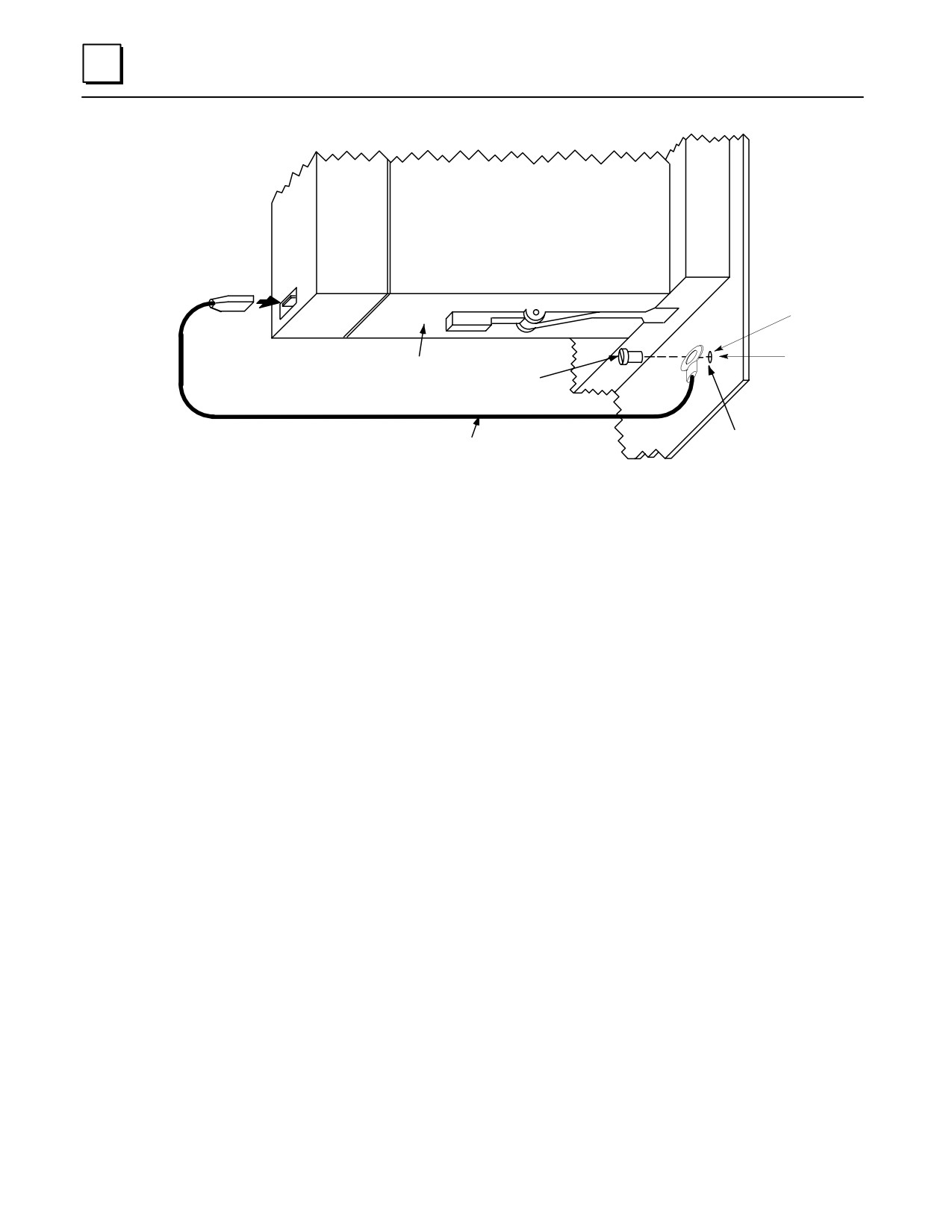
2
CPU363 or 364
STAB-ON
CONNECTOR
#6 TAPPED HOLE
REMOVE PAINT UNDER
BOTTOM
RING TERMINAL OR INSTALL
OF CPU MODULE
STAR LOCK WASHER BETWEEN
USE 1 #6
RING TERMINAL AND PANEL
MACHINE SCREW
MOUNT ON
44A735970-001R01
GROUNDED
ENCLOSURE
Figure 2-14. CPU 363 or CPU364 - Attaching Ground Wire
Additional Modules with Shield Grounding Requirements
Some of the Series 90-30 Option modules, such as the FIP Remote I/O Scanner
(IC693BEM330), and DSM modules (IC693DSM302 and IC693DSM314) also have shield
grounding requirements. These modules come equipped with suitable grounding
hardware. Please refer to each module’s user ’s manual for grounding instructions.
Appendix I contains a product to publication cross-reference to help you identify the
correct manual.
2-16
Series 90-30 PLC Installation and Hardware Manual - October 1999
GFK-0356P
2
General Wiring Guidelines
Warning
In addition to the following wiring suggestions, we strongly urge that
you follow all wiring and safety codes that apply to your area or your
type of equipment. For example, in the United States, most areas have
adopted the National Electrical Code standard and specify that all
wiring conform to its requirements. In other countries, different codes
will apply. For maximum safety to personnel and property you must
follow these codes. Failure to do so can lead to personal injury or
death, property damage or destruction, or both.
Color Coding Wires
These color codes are commonly used in industrial equipment manufactured in the
United States. They are cited here as a reference. Where they are in conflict with codes
that apply to your area or your type of equipment, you should follow your applicable
codes instead. Besides satisfying code requirements, wire color coding makes testing
and troubleshooting safer, faster, and easier.
Green or green with stripe- Ground
Black - Primary AC
Red - Secondary AC
Blue - DC
White - Common or neutral
Yellow - Secondary power source not controlled by the main disconnect. Alerts
maintenance personnel that there may be power present (from an external
source) even if the equipment is disconnected from its main power source.
Wire Routing
To reduce noise coupling among PLC wires, it is recommended you keep electrically
noisy wiring, such as AC power wiring and Discrete Output Module wiring, physically
separated from low-level signal wiring such as DC and Analog Input module wiring or
communications cables. This can be accomplished by grouping separately, where
practical, the following categories of wiring:
AC power wiring. This includes the AC input to the PLC power supply, as
well as other AC devices in the control cabinet.
Analog Input or Output Module wiring. This should be shielded to further
reduce noise coupling. See the Series 90-30 I/O Module Specifications Manual,
GFK-0898 for details.
Discrete Output Module wiring. These often switch inductive loads that
produce noise spikes when switched off.
DC Input Module wiring. Although suppressed internally, these low-level
inputs should be further protected against noise coupling by observing
these wiring practices.
GFK-0356P
Chapter 2 Installation
2-17
2
Communications Cables. Wiring such as Genius Bus or serial cables should
be kept away from noise-producing wiring.
Where AC or Output wiring bundles must pass near noise-sensitive signal wiring
bundles, avoid running them beside each other. Route them so that, if they have to
cross, they do so at a right angle. This will minimize coupling between them.
Grouping Modules to Keep Wires Segregated
If practical, grouping similar modules together in the PLC racks can help keep wiring
segregated. For example, one rack could contain only AC modules, and a different rack
only DC modules, with further grouping in each rack by input and output types. For
smaller systems, as an example, the left end of a rack could contain Analog modules, the
middle could contain DC modules, and the right end could contain AC modules.
Discrete I/O Module Connection Methods
For modules with 16 points or less, the standard method is to use the removable
terminal board which comes with these modules. The removable terminal
board makes it easy to prewire field wiring to the user supplied input and
output devices, and to replace modules in the field without disturbing existing
field wiring.
Some discrete 16-point I/O modules can be used with an optional Terminal Block
Quick Connect (TBQC) assembly. This assembly contains a module faceplate,
with built-in connector, that replaces the removeable terminal board. The
assembly also contains a DIN-rail mounted terminal block and a cable to connect
the module to the terminal block. The advantage of this method is that it saves
about two hours of wiring time per module compared with hand wiring from a
module’s removable terminal board to a user-supplied, panel-mounted terminal
block or strip.
Older 32-point I/O modules have one 50-pin connector on the front of the
module that is either connected by a cable with a connector on each end to a
Weidmuller panel-mounted terminal block (Weidmuller catalog no. 912263), or is
connected by a cable with stripped, tinned leads to a user-supplied terminal
block or strip.
Newer 32-point I/O modules have two 24-pin connectors on the front of the
module. These module may be wired in one of three ways. (1) Use a pair of
cables (IC693CBL327/328 - see data sheet in “Cables” chapter) to connect the
module to a user-supplied, panel-mounted terminal block or strip. These cables
have a 24-pin connector on one end, and stripped, tinned leads with wire
markers on the other end. (2) Use a pair of dual-connector cables to connect the
module to a Terminal Block Quick Connect (TBQC) terminal block
(IC693ACC377). See Appendix J for details. (3) Make your own custom cables.
Instructions are found in the IC693CBL327/328 data sheet in Chapter 10.
Connections to I/O Module Terminal Boards
Series 90-30 PLC I/O terminal boards have either 10 or 20 screw terminals that will
accept from two AWG #22 (0.36 mm2) to two AWG #16 (1.3 mm2), or one AWG #14 (2.1
mm2) copper 90 C (194 F) wire(s). Each terminal can accept solid or stranded wires, but
the wires into any given terminal should be the same type (both solid or both stranded)
2-18
Series 90-30 PLC Installation and Hardware Manual - October 1999
GFK-0356P
2
to ensure a good connection. Wires are routed to and from the terminals out of the
bottom of the terminal board cavity. The suggested torque for the I/O terminal board
connection screws is from 9.6 in-lbs to 11.5 in-lbs (1.1 - 1.3 Newton-meters).
For 24 volt DC input modules, an internal 24 volt power connection is provided on the
terminal board to supply a limited number of input devices. Also, a 24 volt DC output
is available on the power supply module’s terminal board to supply a limited number of
output devices.
Terminal Block Quick Connect Installation for 16-Point Discrete Modules
The Terminal Block Quick Connect (TBQC) Assembly is an option for certain Series 90-30
discrete I/O modules. See Appendix J for more information.
Remove standard terminal board from module.
Install TBQC faceplate (it has a 24-pin connector).
Mount the TBQC terminal block. It has a 24-pin connector and a terminal strip, and
mounts on a standard 35 mm DIN-rail.
Connect a TBQC cable between the TBQC faceplate connector on the module and
the connector on the TBQC terminal block.
Wire I/O devices to the terminal block.
Installation of 32-Point Discrete, 50-Pin Connector Modules
These 50-Pin modules are an older design and are not generally used on new systems,
unless to fulfill standardization requirements. They are mainly used as replacements for
existing installations. For new installations, we recommend the dual 24-pin connector
style because they have additional features not found on the older modules (LED
indicators, TBQC), and it is much easier to fabricate custom-length cables for them.
Installation information is provided here for the convenience of those still using these
modules.
Using Weidmuller
#912263 Terminal Block
Note: The TBQC is not available for these modules, but you may purchase a Weidmuller
#912263 from your electronics distributor for this application.
Mount the Weidmuller#912263 terminal block. It has a 50-pin connector and a
terminal strip, and mounts on a standard 35 mm DIN-rail.
Connect an IC693CBL306/307 cable between the module’s faceplate connector and
the connector on the Weidmuller terminal block. See Chapter 10 for cable data.
Wire I/O devices to the terminal block. See the Series 90-30 PLC I/O Module
Specifications Manual, GFK-0898, for pin-out information.
GFK-0356P
Chapter 2 Installation
2-19
2
Using Generic Terminal Block or Strip
Mount terminal block/strip to the enclosure panel.
Connect an IC693CBL308 or 309 cable, or a custom made cable, to the module’s
faceplate connector and wire the stripped ends of the cable to the terminal
block/strip. See Chapter 10 for cable data.
Wire I/O devices to the terminalblock/strip.
Direct Method
Connect an IC693CBL308 or 309 cable, or a custom made cable, to the module’s
faceplate connector and wire the stripped ends of the cable directly to the field
devices. See Chapter 10 for cable data. See the Series 90-30 PLC I/O Module
Specifications Manual, GFK-0898, for pin-out information.
Installation of Discrete 32-Point, Dual 24-Pin Connector Modules
Using a TBQC
Mount two TBQC terminal blocks. Each has a 24-pin connector and a terminal strip,
and mounts on a standard 35 mm DIN-rail.
Connect a pair of TBQC cables (IC693CBL329 - 334) between the module’s
faceplate connector and the connectors on the two TBQC terminal blocks. Note that
both a right side and left side cable is required. See Appendix J for a list of cables.
Wire I/O devices to the terminal blocks. See the Series 90-30 PLC I/O Module
Specifications Manual, GFK-0898, for pin-out information.
The Terminal Block Quick Connect (TBQC) Assembly is an option for certain Series 90-30
discrete I/O modules. See Appendix J for more information.
With a Generic Terminal Block/Strip
Mount terminal block/strip to the enclosure panel.
Connect an IC693CBL327/328 cables, or a custom made cables, to the module’s
faceplate connectors, and wire the stripped ends of the cables to the terminal
block/strip. Note that both a right side and left side cable is required. See Appendix
J for a list of cables. See Chapter 10 for cable data sheets.
Wire I/O devices to the terminal block/strip. See the Series 90-30 PLC I/O Module
Specifications Manual, GFK-0898, for pin-out information.
Direct Method
Connect an IC693CBL327/328 cables, or a custom made cables, to the module’s
faceplate connectors, and wire the stripped ends of the cable directly to the field
devices. See Chapter 10 for cable data. See the Series 90-30 PLC I/O Module
Specifications Manual, GFK-0898, for pin-out information.
2-20
Series 90-30 PLC Installation and Hardware Manual - October 1999
GFK-0356P
2
General Wiring Methods for Analog Modules
Twisted, shielded instrumentation cable is strongly recommended for analog module
input or output signal connections. Proper grounding of the shield is also important.
For maximum electrical noise suppression, the cable shield should only be grounded at
one end of the cable. For Input modules, ground the end that is in the noisiest
environment (which often is at the field device end). For Output modules, ground at the
module end. See GFK-0898, Series 90-30 PLC I/O Module Specifications, for more shield
grounding information.
Analog Input Module Wiring Methods
Correcting electrical noise problems can sometimes be a trial-and-error routine.
However, in general, it is generally best to ground the cable shield as close to the source
of the noise as possible, which is usually at the device end. In troubleshooting noise
problems, sometimes it is beneficial to experiment with the shield grounding point
location. Remember, the cable shield should be grounded at one end only. Also, it is best
to keep the length of stripped cable leads as short as possible to minimize the length of
unshielded conductors that will be exposed to the noisy environment. See the Series
90-30 PLC I/O Module Specifications Manual, GFK-0898 for additional details.
Using Generic Terminal Block or Strip
Mount a terminal strip inside the control enclosure and run a shielded cable from
the terminal strip to each input circuit on the module’s terminal board terminals.
Connect each cable’s shield to the metal panel next to the terminal strip. Do do not
connect the shields at the module end (cut shield off at module end of cable and
insulate with shrink tubing).
Wire the field device to the terminal strip with a shielded cable, grounding the shield
at the device end only (cut shield off at terminal strip end of cable and insulate with
shrink tubing). Also, keep the length of exposed (outside of shield) leads at the
terminal strip and device ends as short as possible.
Direct Method
Run a shielded cable from the field device (transducer, potentiometer, etc.) directly
to the module.
Connect the conductors to the applicable screws on the module’s terminal board.
Ground the shield at the field device end, exposing a minimum amount of
conductor to the noisy environment. Do not connect the shield at the module end
(cut shield off at module end of cable and insulate with shrink tubing).
TBQC
The Terminal Block Quick Connect (TBQC) Assembly is not recommended for use with
analog modules due to cable shielding requirements.
GFK-0356P
Chapter 2 Installation
2-21
2
Analog Output Module Wiring
General
Each output should be connected using a good quality shielded wire with the cable
shield grounded at the module end. See GFK-0898, Series 90-30 PLC I/O Module
Specifications, for more information.
Using Generic Terminal Block or Strip
Mount a terminal strip inside the control enclosure and run a shielded cable from
the terminal strip to each output circuit on the module’s terminal board terminals.
Ground each cable’s shield at the module end only. Do do not connect the shields at
the terminal strip end (cut shields off at terminal strip end of cables and insulate
with shrink tubing).
Wire the field device to the terminal strip with shielded cables, grounding the
shields at the terminal strip end only (cut shields off at field device end of cables and
insulate with shrink tubing). Also, keep the length of exposed (outside of shield)
leads at the terminal strip and device ends as short as possible.
Direct Method
Run a shielded cable from each field device (transducer, potentiometer, etc.) directly
to the module.
Connect the conductors to the applicable screws on the module’s terminal board.
Ground the shield at the module end only, exposing a minimum amount of
conductor to the noisy environment. Do not connect the shield at the device end
(cut shield off at device end of cable and insulate with shrink tubing).
TBQC
The Terminal Block Quick Connect (TBQC) Assembly is not recommended for use with
analog modules due to cable shielding requirements.
2-22
Series 90-30 PLC Installation and Hardware Manual - October 1999
GFK-0356P
2
AC Power Source Connections
AC Input Wiring to AC/DC Power Supplies
Warning
If the same AC power source is used to provide AC power to other baseplates
in a Series 90-30 PLC System, ensure that all AC input connections are
identical at each rack. Do not cross Line 1 (L1) and Line 2 (L2). A resulting
difference in potential can injure personnel or cause damage to equipment.
Each baseplate must be connected to a common ground.
Ensure that the protective cover is installed over all terminal boards. During
normal operation with an AC power source either 120 VAC or 240 VAC is
present on the AC Power Supply. The cover protects against accidental
shock hazard which could cause severe or fatal injury to the operator or
maintenance personnel.
Both the Standard (IC693PWR321) and High Capacity (IC693PWR330) AC/DCpower
supplies currently have six terminals for user connections. Early versions of some Series
90-30 power supplies had five terminals (see next figure). The wiring methods for both
five-terminal and six-terminal types is similar, except that step 3 below does not apply to
the five-terminal type.
The power supply terminal boards will accept one AWG #14 (2.1 mm2) or two AWG #16
(1.3 mm2) copper 75 C (167 F) wires. Each terminal can accept solid or stranded wires,
but the wires in any given terminal should be the same type. The suggested torque for
the power supply terminal board is 12 in-lbs (1.36 Newton-meters). Open the door
protecting the terminal board and make the following connections from the AC power
source, and ground connections (system grounding requirements are described in detail
later in this chapter).
1.
These are wide range supplies that can operate from an AC power source within the
nominal range of 100 VAC to 240 VAC at 50/60 Hz. This may vary -15% to +10%
for a total maximum range of 85 VAC to 264 VAC. These are auto-ranging supplies
that do not require jumper or switch settings for selection of power source voltage.
2.
Connect the hot and neutral wires or lines L1 and L2 to the upper two terminals on
the terminal board. Connect the safety ground wire to the ground terminal, which
is the third terminal from the top, and is marked with a ground symbol.
3.
For power supplies with six terminals, the factory jumper between the 3rd and 4th
terminals (see figure below), should be left in place for normal installations.
However, this jumper must be removed and external surge suppressors installed in
installations with a “Floating Neutral” input. Please see the section “Special
Instructions for Floating Neutral (IT) Systems” later in this chapter for details.
4.
After all connections to Power Supply terminal board have been completed, the
protective cover plate should be carefully reinstalled.
GFK-0356P
Chapter 2 Installation
2-23
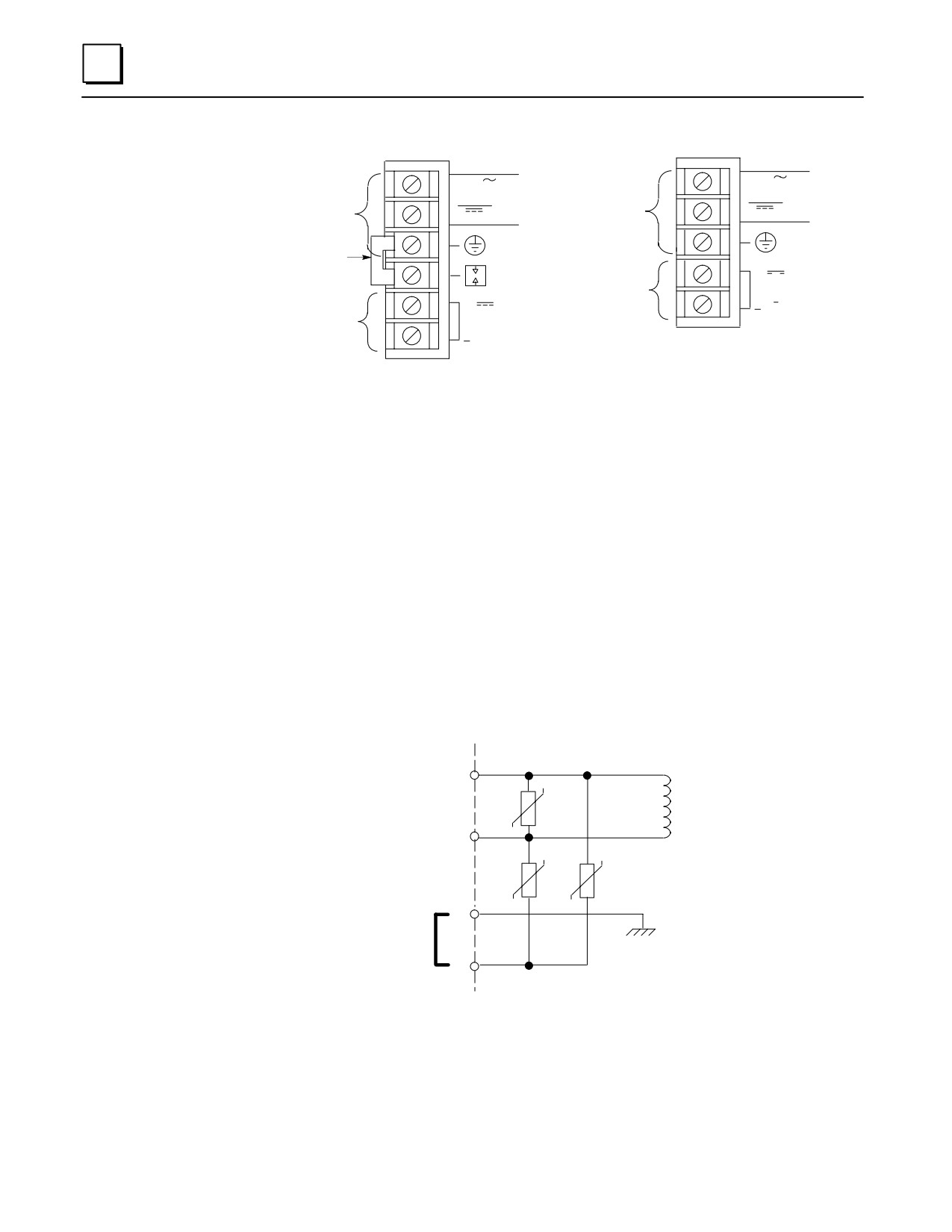
2
INPUT
INPUT
100-240 VAC
100-240 VAC
50/60HZ 90VA
50/60HZ 90VA
Input Power
125 VDC, 50W
Input Power
125 VDC, 50W
Factory Jumper
+
24 VDC Output
24 VDC
OUTPUT
For I/O Modules
+
0.8A MAX.
24 VDC Output
24 VDC
For I/O Modules
OUTPUT
0.8A MAX.
Six-Terminal Board
Five-Terminal Board
Figure 2-15. Power Supply Terminal Boards
Power Supply Overvoltage Protection Devices
The overvoltage protection devices for this power supply are connected internally to pin 4
on the user terminal board. This pin is normally connected to frame ground (pin 3) with
the supplied jumper strap which is installed at the factory. If overvoltage protection is not
required or is supplied upstream, this feature can be disabled by leaving pin 4 unconnected
by removing the jumper strap. Also, this jumper must be removed and external surge
suppressors installed in installations with a “Floating Neutral” input, please see the
following section “Special Instructions for Floating Neutral (IT) Systems” later in this
chapter.
If you want to Hi-pot test this supply, overvoltage protection must be disabled during the
test by removing the terminal board strap. Re-enable overvoltage protection after
testing by reinstalling the strap.
a47086
1
2
3
Frame Ground
Jumper Strap Connects
Overvoltage Protection
Devices to Frame Ground
4
Screw Terminals on Terminal Board
Figure 2-16. Overvoltage Protection Devices and Jumper Strap
2-24
Series 90-30 PLC Installation and Hardware Manual - October 1999
GFK-0356P
2
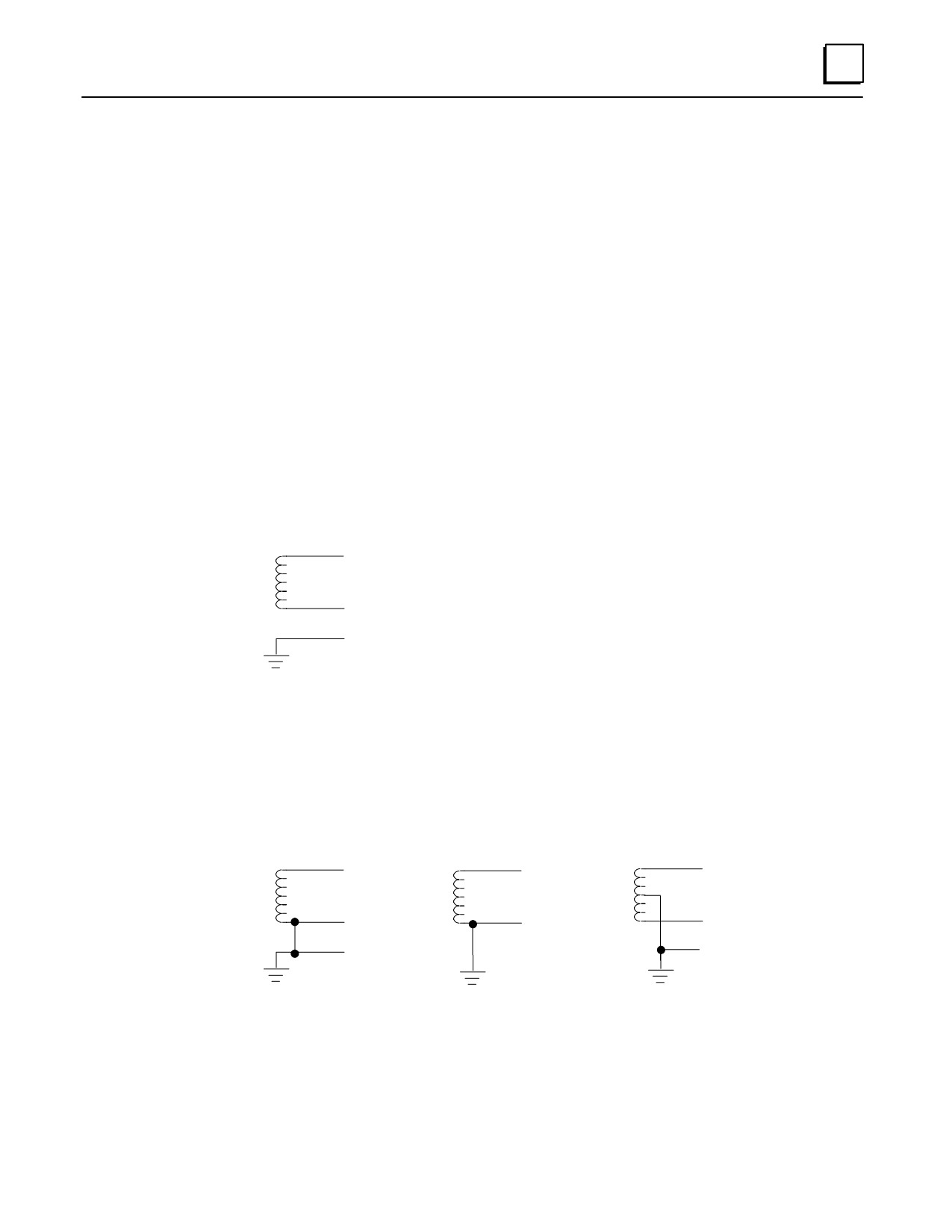
Special Installation Instructions for Floating Neutral (IT) Systems
When the AC input power supplies listed below are installed in a system where the
Neutral line is not referenced to Protective Earth Ground, these special installation
instructions must be followed to prevent damage to the power supply.
IC693PWR321S (or later version)
IC693PWR330A (or later version)
Definition of Floating Neutral Systems
A Floating Neutral System is a system of power distribution wiring where Neutral and
Protective Earth Ground are not tied together by a negligible impedance. In Europe this is
referred to as an IT system (see IEC950). In a Floating Neutral System, voltages measured
from input terminals to protective earth ground may exceed the 264 Volts AC maximum
input voltage specified in the power supply specifications in Chapter 24in this manual.
Example of Floating Neutral System
L1
N
PE
This system must be installed using the special installation instructions on the following
page.
Systems in which one leg of the power distribution wiring is tied to Protective Earth or a
tap between two legs of the power distribution wiring is tied to Protective Earth are not
Floating Neutral Systems.
Examples of Non-Floating Neutral System
L1
L
L1
N
N/PE
L2
PE
PE
These non-floating neutral systems do not require these special installation instructions.
GFK-0356P
Chapter 2 Installation
2-25
2
Use These Special Installation Instructions for Floating Neutral Systems
1.
The input power terminals should be wired according to the instructions in the “AC
Power Source Connections” section of this chapter.
2.
The factory installed jumper between terminals 3 and 4 of the Power Supply module
must be removed if using one of the Power Supplies that have this feature. See the
“Overvoltage Protection Devices” section of the “Power Supplies” chapter for details.
3.
Voltage surge protection devices, such as MOVs, MUST be installed between the
following terminals:
From L1 to earth ground
From L2 (Neutral) to earth ground
The voltage surge devices must be rated such that the system is protected from power
line transients that exceed Line voltage + 100V +(N-PE)MAX.
The expression N-PE refers to the voltage potential between neutral and Protective
Earth (PE) ground.
For example, in a 240 Volt AC system with neutral floating 50V above earth ground, the
transient protection should be rated at:
240V + 100V +50V = 390V
2-26
Series 90-30 PLC Installation and Hardware Manual - October 1999
GFK-0356P
2
DC Power Source Connections
DC Input Wiring to AC/DC and DC-Only Power Supplies
DC Input power can range from 12 to 30 VDC for the 24 VDC supply, 18 to 56 VDC for
the 24/48 VDC supply or 100 to 150 VDC for the 125 VDC supply. All Series 90-30 power
supplies have DC input capabilities. The following connection information applies to all
of them:
Connect the + and - wires from the power source to the top terminals on the terminal
board (+ to the top terminal, - to the second terminal). Connect the third terminal
from the top to system ground.
+24 VDC Output (All Supplies)
The bottom two terminals are connected to the isolated 24 volt DC output that can be
used to supply power to input circuits (within power limitations of the supply).
Warning
If the same DC input power source is used to provide power to two or
more power supplies in a Series 90-30 PLC System, ensure that
connection polarity is identical at each rack (top terminal + and second
terminal -). Do not cross the Positive (+) and Negative (-) lines. A
resulting difference in potential can injure personnel or cause damage
to equipment. Also, each baseplate must be connected to a common
system ground, described earlier in this chapter.
GFK-0356P
Chapter 2 Installation
2-27
2
Basic Installation Procedure
The system design, which includes producing the layout and wiring drawings, should be
completed before beginning the installation procedure. This section offers a basic
step-by-step approach to installing a Series 90-30 PLC system. Some steps refer to earlier
sections of this chapter for additional details. An attempt was made to place the steps in
an order that will make the process as efficient as possible. However, due to the wide
variance in system designs, this order may not be the most efficient for your system, so
you may wish modify this procedure to fit your needs.
1.
Gather the schematics, layouts, prints, and other information for the job.
Warning
To avoid the possibility of electrical shock to personnel or damage to
your PLC, we recommend that you shut off all power to the system
before mounting and wiring the PLC. Also, keep all electronic
components away from the area while drilling and tapping to keep
metal chips and filings out of these sensitive components.
2.
From the layout drawing, determine where the baseplate(s) will be mounted. Lay
out the hole locations, either using the dimensions given on your layout drawing or
from the “Baseplates” chapter of this manual.
3.
Mark the hole locations for the baseplate safety ground wire (see “Baseplate Safety
Ground” in this chapter).
4.
Mark the hole locations for module shield ground connections (if any). See “Module
Shield Ground” (and accompanying sections) in this chapter for instructions.
5.
Finish laying (marking hole locations) out the rest of the system. This includes any
terminal blocks you will be using. DIN-rail mounted terminal blocks for some of the
32-point I/O modules are manufactured by Weidmuller. DIN-rail mounted GE
Fanuc Terminal Block Quick Connect (TBQC) assemblies are optional for some of the
16-point and 32-point discrete I/O modules. If using these TBQCs, refer to Appendix
J for data. Also, APM and DSM modules use DIN-rail mounted terminal blocks.
Note
We recommend drilling and tapping all holes before mounting any
components. This will avoid getting chips and filings in the
components.
6.
Drill and tap the marked holes. For baseplate mounting, use 8-32 or 4mm size.
7.
Mount the baseplates. Use good quality 8-32 x 1/2 inch or 4 x 12mm size screws. We
recommend using star lock washers and flat washers under the screw heads (star
lock washer should be located between screw head and flat washer) to ensure a
tight baseplate ground connection, and to keep the screws from loosening. Connect
each baseplate ground wire as shown in the “Baseplate Safety Ground” section of
this chapter.
8.
If you have Expansion or Remote racks, determine the correct rack number for each
one, then set the rack numbers using the Rack Number Selection DIP switch on the
baseplate. Please refer to the “Baseplates” chapter for details on setting these DIP
switches. Rack numbers should be assigned by the system programmer because
they correspond to system configuration settings and program memory addressing.
2-28
Series 90-30 PLC Installation and Hardware Manual - October 1999
GFK-0356P
2
9.
If you have more than one baseplate (rack), connect the I/O Bus Expansion Cables
between the I/O Bus Expansion Connectors, which are located on the right end of
the baseplates. The cables are connected in a “daisy-chain” arrangement from one
baseplate to the other. This is made possible by the fact that the cables have a dual
connector on one end. Therefore, when the cable is plugged into a baseplate
connector, the second connector on that end of the cable provides a socket for
connecting to the next cable. The data sheet for the I/O Bus Expansion cables
(IC693CBL300 etc.) in the “Cables” chapter has sample wiring figures.
10.
On the last I/O Bus Expansion Connector, plug in an I/O Bus Expansion Terminator,
Catalog Number IC693ACC307 (unless using a cable with built-in terminator
resistors, which would either be GE Fanuc cable IC693CBL302, or your own
custom-built cable).
11.
Install the modules in their correct slots using your system layout drawings. (The
label on the side of each module identifies the module type and catalog number.)
Refer to the section “Installing Modules” if you are not familiar with how to do this.
12.
Connect cables to Option modules. Route cables away from noise-producing wires.
See the ”Wire Routing” section of this chapter.
13.
Be sure to follow the information in the “Wiring Guidelines” section of this chapter
to protect the system from electrical noise. Install the power wires to the Power
Supply and I/O modules:
I/O modules with removeable terminal boards. You can wire the terminal
boards in-place on the modules or remove them from the modules before
wiring. Although removing them may help make wiring easier (a previous
section “Working with Removeable Terminal Boards” shows how to remove a
terminal board), care should be taken to avoid mixing them (each terminal
board has the catalog number of the module printed on it, and the hinged cover
has a wiring diagram for that module type). If you are using wire duct, routing
each module’s wires through the opening in the duct directly under the module
will help to keep each terminal board in its correct position.
I/O Modules with terminal blocks. Some modules use terminal blocks that
mount to the enclosure panel. This includes all 32-point modules and, can
include other I/O modules if they are fitted with the optional Terminal Block
Quick Connect Assembly. Connect the terminal blocks to the connectors on the
modules with the provided cables.
14.
Connect the signal (switches, sensors, solenoids, etc.) wires to the terminal boards, or
terminal blocks/strips. If wiring to terminal boards, these can be removed for ease of
wiring, if desired. See the section “Removing a Module’s Terminal Board.”
15.
When finished wiring the I/O terminal boards (if used and if you removed them for
ease of wiring), re-install them on the modules, being careful to match each one with
the correct module.
GFK-0356P
Chapter 2 Installation
2-29