FANUC Series 90-30 PLC. Installation and Hardware Manual (GFK-0356P) - page 1
Preface
This manual describes the GE Fanuc Series 90
-30 Programmable Logic Controller
(PLC). It contains a description of hardware components and provides basic hardware
installation procedures. The Series 90-30 PLC is a member of the Series 90
family of
Programmable Logic Controllers from GE Fanuc.
For a list of product standards, refer to data sheet GFK-0867B or later, GE Fanuc Approvals,
Standards, General Specifications which lists all of the standards for GE Fanuc products.
Installation instructions in this manual are provided for installations that do not require
special procedures for noisy or hazardous environments. For installations that must
conform to more stringent requirements (such as CE Mark), see GFK-1179, Installation
Requirements for Conformance to Standards.
What’s New in This Manual
This manual has been rearranged into 13 chapters, each covering a specific topic
such as Installation, Baseplates, Power Supplies, CPUs, Option Modules, etc.
Chapter 5 contains information about CPU models IC693CPU363 and IC693CPU364
and CPU firmware release 9.00 features for CPUs 350 - 364.
Chapter 7 contains information about the IC693DVM300 Digital Valve Driver
module.
Preliminary information about Option modules IC693DSM314 and
IC693PTM100/101 (Chapter 8), and Power Supply IC693PWR328 (Chapter 4) has
been added.
Chapter 6 contains information on memory backup strategy and on the backup
battery, including such things as reading battery date codes and estimating battery
life.
Chapter 10 includes additional information on both new and old cables, including a
cable-to-product cross-reference table.
Chapter 12 introduces a new subject, System Design, to this manual. It describes
factors to consider and specifications needed for designing a Series 90-30 system.
Chapter 13 presents information on the subject of maintenance and troubleshooting
and includes information on obtaining technical help and information via the Web
site, Fax Link, and Technical Support telephone numbers.
Appendix G discusses new port isolator IC690ACC903.
A new section describing how to calculate Series 90-30 heat dissipation can be found
in Appendix H.
A product to publication number cross-reference has been added (Appendix I) to
help you find documentation for Series 90-30 products.
Appendix J includes information on the new Terminal Block Quick Connect
(IC693ACC377) and associated cables for 32-point modules.
Appendix K covers the subject of SNP Multidrop.
Appendix L contains data on Ethernet Transceivers IC649AEA102 and IC649AEA103.
Appendix M contains useful tables and formulas.
Some of the new modules and/or other products referenced above may not be available when
this manual is printed. For current availability of features and products consult your local
GE Fanuc PLC distributor or GE Fanuc sales representative.
GFK-0356P
Preface
v
Preface
Content of this Manual
Chapter 1. Overview of the Series 90-30 PLC: This chapter provides you with an
introduction to the Series 90-30 Programmable Logic Controller products and an
overview of how they fit together into a system.
Chapter 2. Installation: Provides information such as mounting, wiring, and grounding
Series 90-30 components.
Chapter 3. Baseplates: Baseplate types, descriptions, and specifications.
Chapter 4. Power Supplies: Power supply types, descriptions, and specifications.
Chapter 5. CPUs: CPU types, descriptions, and specifications.
Chapter 6. Memory Backup and Backup Battery: Discusses various memory backup
strategies as well as battery issues, such as battery life estimation and date code
interpretation.
Chapter 7. Input and Output Modules: Covers an overview of these modules. This
chapter refers you to the Series 90-30 I/O Module Specifications Manual (GFK-0898) for
details on these modules.
Chapter 8. Option Modules: Covers an overview of these modules. This chapter refers
you to the various manuals that cover these modules in detail.
Chapter 9. State Logic Products: Covers an overview of these modules. This chapter
refers you to the various manuals that cover these modules in detail.
Chapter 10. Cables: Contains a cable-to-product cross-reference table as well as data
sheets for the Series 90-30 cables.
Chapter 11. Programmer Hardware Products. Discusses such things as WSI boards,
PCIF cards, and converters and isolators.
Chapter 12. System Design: Factors to consider when designing a Series 90-30 PLC
system. Includes specifications and layout information needed for the design process.
Chapter 13. Maintenance: Features of Series 90-30 hardware and software that are
useful for troubleshooting. Also contains tables of spare parts and preventive
maintenance suggestions, and a fuse-to-module cross-reference. Includes information
on accessing GE Fanuc technical help resources such as Fax Link and our Web site.
Appendix A. Glossary: Contains terms relevant to the Series 90-30 PLC and to
Programmable Logic Controllers in general.
Appendix B. Commonly used Acronyms.
Appendix C. Serial Port and Cables: Serial port and cable specifications.
Appendix D. IC690ACC900 Converter: Contains detailed information about this obsolete
product.
Appendix E. IC655CCM590 Isolated Repeater/Converter: Contains detailed
information about this obsolete product
Appendix F. IC690ACC901 Miniconverter Kit: Product description and specifications.
Appendix G. IC690ACC903 Port Isolator: Product description and specifications.
vi
Series 90-30 PLC Installation and Hardware Manual
GFK-0356P
Preface
Appendix H. Series 90-30 Heat Dissipation: How to calculate heat dissipation for the
purpose of sizing enclosures.
Appendix I. Catalog Number to Publication Cross-Reference: Lists applicable
publications for Series 90-30 product catalog numbers.
Appendix J. Terminal Block Quick Connect. Describes the Terminal Block Quick
Connect system, which consists of an interposing terminal block, faceplate, and cable.
This assembly allows faster wiring of some discrete I/O modules.
Appendix K. SNP Multidrop. Explains how to connect a programming unit to multiple
PLCs and/or Option modules.
Appendix L. Ethernet Transceivers. Data on the two transceivers sold by GE Fanuc.
Appendix M. Tables and Formulas. Contains information such as Fahrenheit to Celsius
temperature conversion, AWG wire sizes to Metric conversion, ASCII codes, Metric to
English units conversions, etc.
Appendix N. 44A720084-001 EMI Line Filter. Describes the optional EMI line filter that
was used on some early versions of the Series 90-30 PLC to meet FCC EMI requirements
for non-industrial applications.
GFK-0356P
Preface
vii
Preface
Related Publications:
For more information on Series 90-30 products, refer to these publications (note: a
publication to product catalog number cross-reference is provided in Appendix H):
GFK-0255 - Series 90 PCM and Support Software User’s Manual
GFK-0256 - MegaBasic Programming Reference Manual
GFK-0293 - Series 90-30 High Speed Counter User’s Manual
GFK-0401 - Workmaster® II PLC Programming Unit Guide to Operation
GFK-0402 - Series 90-30 and 90-20 PLC Hand-Held Programmer User’s Manual
GFK-0412 - Genius® Communications Module User’s Manual
GFK-0466 - Logicmaster 90 Series 90-30/20/Micro Programming Software User’s Manual
GFK-0467 - Series 90-30/20/Micro Programmable Controllers Reference Manual
GFK-0487 - Series 90 PCM Development Software (PCOP) User’s Manual
GFK-0499 - CIMPLICITY® 90-ADS Alphanumeric Display System User’s Manual
GFK-0582 - Series 90 PLC Serial Communications User’s Manual
GFK-0631 - Series 90-30 I/O LINK Interface User’s Manual
GFK-0641 - CIMPLICITY® 90-ADS Alphanumeric Display System Reference Manual
GFK-0664 - Series 90-30 PLC Axis Positioning Module Programmer’s Manual
GFK-0685 - Series 90 Programmable Controllers Flow Computer User ’s Manual
GFK-0695 - Series 90-30 Enhanced Genius® Communications Module User ’s Manual
GFK-0726 - Series 90-30 PLC State Logic ProcessorUser ’s Guide
GFK-0732 - Series 90-30 PLC ECLiPS User ’s Manual
GFK-0747 - Series 90-30 PLC OnTOP User ’s Guide
GFK-0750 - OnTop for Series 90-30 (State Logic) ProgramUser ’s Manual
GFK-0781 - Motion Mate APM300 for Series 90-30 PLC Follower Mode User ’s Manual
GFK-0823 - Series 90-30 I/O LINK Master Module User ’s Manual
GFK-0828 - Series 90-30 Diagnostic System User ’s Manual
GFK-0840 - Motion Mate APM300 for Series 90-30 PLC Standard Mode User ’s Manual
GFK-0867 - GE Fanuc Product Agency Approvals, Standards, General Specifications
GFK-0898 - Series 90-30 PLC I/OModule Specifications
GFK-1028 - Series 90-30I/OProcessorModule User ’s Manual
GFK-1034 - Series 90-30 Genius® Bus Controller User ’s Manual
GFK-1037 - Series 90-30 FIP Remote I/O Scanner User ’s Manual
GFK-1056 - Series 90-30 State Logic Control System User ’s Manual
GFK-1186-TCP/IPEthernet Communications for the Series 90
-30 PLC Station Manager Manual
GFK-1179 - Series 90 PLC Installation Requirements for Conformance to Standards
GFK-1464 - Motion Mate DSM302 for Series 90
-30 PLCs User ’s Manual
GFK-1466 - Temperature Control Module for the Series 90
-30 PLC User ’s Manual
GFK-1541-TCP/IPEthernet Communications for the Series 90
PLC User ’s Manual
viii
Series 90-30 PLC Installation and Hardware Manual
GFK-0356P
Preface
We Welcome Your Comments and Suggestions
At GE Fanuc Automation, we strive to produce quality technical documentation. After
you have used this manual, please take a few moments to complete and return the
Reader ’s Comment Card located on the next page.
Thomas W. Myrtle
Senior Technical Writer
GFK-0356P
Preface
ix
Contents
Chapter 1
Overview of the Series 90-30 PLC
1-1
The Basic Parts of a Series 90-30 PLC
1-1
Assembling a Basic Series 90-30 PLC System
1-2
What else would be needed to make this basic system functional?
1-6
What if the application requires more than five modules?
1-6
What if the application requires more than ten modules?
1-7
What is the Difference Between Expansion and Remote baseplates? . . .
1-8
What if I need to cover more than 700 feet (213 meters) ?
1-9
Chapter 2
Installation
2-1
Receiving your Products - Visual Inspection
2-1
Pre-installation Check
2-1
Warranty Claims
2-1
Working with Series 90-30 Modules
2-2
Baseplate Mounting
2-8
Mounting a Baseplate to a Panel
2-8
Mounting a Baseplate to a 19” Rack
2-8
Grounding Procedures
2-11
System Grounding Procedures
2-11
Series 90-30 PLC Equipment Grounding
2-12
Module Shield Grounding
2-14
General Wiring Guidelines
2-17
Discrete I/O Module Connection Methods
2-18
Connections to I/O Module Terminal Boards
2-18
Terminal Block Quick Connect Installation for 16-Point Discrete Modules
2-19
Installation of 32-Point Discrete, 50-Pin Connector Modules
2-19
Installation of Discrete 32-Point, Dual 24-Pin Connector Modules
2-20
General Wiring Methods for Analog Modules
2-21
Analog Input Module Wiring Methods
2-21
Analog Output Module Wiring
2-22
AC Power Source Connections
2-23
Special Installation Instructions for Floating Neutral (IT) Systems
2-25
Definition of Floating Neutral Systems
2-25
Use These Special Installation Instructions for Floating Neutral Systems
2-26
DC Power Source Connections
2-27
Basic Installation Procedure
2-28
Table of Contents
xi
GFK-0356P
Contents
Chapter 3
Baseplates
3-1
Baseplate Types
3-1
Baseplate Terms Explained
3-3
CPU Baseplates
3-4
Expansion Baseplates (Figures 3-6 and 3-7)
3-8
Remote Baseplates (Figures 3-8 and 3-9)
3-10
Expansion Rack Connection Example
3-16
Expansion and Remote Baseplates Connection Example
3-17
Baseplate Mounting Dimensions
3-18
Load Ratings, Temperature, and Mounting Position
3-21
Baseplate Adapter Brackets for 19” Rack Mounting
3-22
Chapter 4
Power Supplies
4-1
Power Supply Categories
4-1
Power Supply Feature Comparison
4-1
AC/DC Input Power Supplies
4-2
IC693PWR321 Standard Power Supply, 120/240 VAC or 125 VDC Input .
4-2
IC693PWR330 High Capacity Power Supply, 120/240 VAC/125 VDC Input
4-4
Field Wiring Connections for the AC/DC Input Power Supplies
4-5
DC Input Only Power Supplies
4-7
Calculating Input Power Requirements for IC693PWR322
4-8
Calculating Input Power Requirements for IC693PWR328
4-11
IC693PWR331 High Capacity Power Supply, 24 VDC Input
4-13
Calculating Input Power Requirements for IC693PWR331
4-15
Field Wiring Connections to the DC Input-Only Power Supplies
4-16
Common Series 90-30 Power Supply Features
4-17
Output Voltage Connections to Backplane (All Supplies)
4-18
xii
Series 90-30 PLC Installation and Hardware Manual - October 1999
GFK-0356P
Contents
Chapter 5
CPUs
5-1
CPU Types for Series 90-30 PLCs
5-1
Embedded CPUs
5-1
Modular CPUs
5-2
General CPU Features
5-3
Series 90-30 CPU Capacities
5-10
User Memory Addresses (References)
5-11
Difference Between a Memory Address and a Nickname
5-11
User Memory Reference Types
5-11
350 - 364 CPUs
5-13
Hardware Features of the 350 - 364 CPUs
5-18
CPU350 and CPU360 Hardware Features
5-18
CPU351, CPU352, and CPU363 Hardware Features
5-19
CPU364 Hardware Features
5-22
CPU Data Sheets
5-24
CPU313
Catalog Number IC693CPU313
5-26
CPU323
Catalog Number IC693CPU323
5-27
CPU331
Catalog Number IC693CPU331
5-28
CPU340
Catalog Number IC693CPU340
5-29
CPU341
Catalog Number IC693CPU341
5-30
CPU350
Catalog Number IC693CPU350
5-31
CPU351
Catalog Number IC693CPU351
5-32
CPU352
Catalog Number IC693CPU352
5-33
CPU360
Catalog Number IC693CPU360
5-34
CPU363
Catalog Number IC693CPU363
5-35
CPU364
Catalog Number IC693CPU364
5-36
Chapter 6
Memory Backup and Backup Battery
6-1
Backup Battery for RAM Memory (All Supplies)
6-1
Battery Replacement Instructions
6-2
BatteryReplacement/Memory Protection Factors
6-3
Factors Affecting Battery Life
6-4
Low Battery Warning Methods
6-4
Operating Without a Memory Backup Battery
6-5
Determining Battery Age Using Battery Date Code
6-6
RAM Memory Battery Backup Connection Path
6-6
Maintaining RAM Memory During Storage or Shipment of a CPU
6-7
Batteries in Power Supplies on Expansion or Remote Racks
6-9
Table of Contents
xiii
GFK-0356P
Contents
Chapter 7
Input and Output Modules
7-1
Basic I/O Module Types
7-1
Discrete I/OModules
7-3
Wiring Methods for 32-Point Discrete I/O Modules
7-8
Analog Module Features
7-10
Wiring Methods for Analog Modules
7-11
I/O Module Power Supply Current Draw
7-12
I/O Module Wire Routing
7-12
IC693DVM300 Digital Valve Driver Module
7-14
Chapter 8
OptionModules
8-1
IC693CMM301 Genius Communications Module (GCM)
8-2
Status LEDs
8-2
IC693CMM302 Enhanced Genius Communications Module (GCM+) . .
8-4
IC693BEM331 Genius Bus Controller (GBC)
8-6
IC693BEM340 FIP Bus Controller (FBC) Module
8-10
IC693BEM330 FIP Remote I/O Scanner Module
8-12
IC693APU301/302 Motion Mate Axis Positioning Module (APM)
8-15
IC693DSM302 Motion Mate Digital Servo Module (DSM302)
8-17
IC693DSM314 Motion Mate Digital Servo Module (DSM314)
- Preliminary
8-20
IC693APU300 High Speed Counter (HSC) Module
8-24
IC693BEM320 I/O LINK Interface (Slave) Module
8-25
IC693BEM321 I/O LINK Master Module
8-26
IC693APU305 I/O Processor Module
8-28
IC693CMM321 Ethernet Interface Module
8-30
IC693PCM300/301/31P rogrammable Coprocessor Module (PCM)
8-32
IC693CMM311 Communications Coprocessor Module (CMM)
8-34
IC693ADC311 Alphanumeric Display Coprocessor (ADC)
8-35
IC693TCM302/303 Temperature Control Modules (TCM)
8-37
IC693PTM100/101Power Transducer (PTM)- Preliminary
8-40
Chapter 9
State Logic Products
9-1
State Logic Overview
9-1
State Logic Products
9-1
AD693CMM301 State Logic Serial Communications Module (SCM)
9-2
IC693SLP300 State Logic Processor Module
9-4
State Logic CPUs
9-8
State Logic CPU Data Sheets
9-13
CSE311
Catalog Number IC693CSE311
9-14
CSE313
Catalog Number IC693CSE313
9-15
CSE323
Catalog Number IC693CSE323
9-16
CSE331
Catalog Number IC693CSE331
9-17
CSE340
Catalog Number IC693CSE340
9-18
xiv
Series 90-30 PLC Installation and Hardware Manual - October 1999
GFK-0356P
Contents
Chapter 10
Cables
10-1
Cable Data Sheets
10-8
IC647CBL704
Workstation Interface to Series 90 CPU (SNP Port) Cable
10-9
IC690CBL701
PCM, ADC, CMM to Workmaster (PC-XT) Cable
10-13
PCM to Programmer Cable Installation
10-14
IC690CBL702
PC-AT to PCM, ADC, CMM Cable
10-15
PCM to Programmer Cable Installation
10-16
IC690CBL705
Workmaster II (PS/2) to PCM, ADC, CMM Cable
10-17
PCM to Programmer Cable Installation
10-18
IC690CBL714A Multidrop Cable
10-19
Connection Diagrams for IC690CBL714A Cable
10-21
IC693CBL300/301/302/312/313/314
I/O Bus Expansion Cables
10-23
Building Custom Length I/O Bus Expansion Cables
10-25
IC693CBL303
Hand-Hand Programmer and Converter (IC690ACC900) Cable
10-34
IC693CBL304/305
Port Expansion (WYE) Cables for PCM, ADC, and CMM
10-36
IC693CBL306/307
Extension Cables (50-Pin) for 32 Point Modules
10-39
IC693CBL308/309
I/O Cables (50-Pin) for 32 Point Modules
10-41
IC693CBL310
I/OInterface Cable (24-Pin) for 32 Point Modules
10-42
IC693CBL311/317/319/320
I/OInterface Cables for Power Mate APM Modules
10-45
IC693CBL315
I/OInterface Cable (24-Pin) for 32 Point Modules
10-49
IC693CBL316
Serial Cable, 9-Pin D-Shell to RJ-11 Connector
10-53
IC693CBL321/322/323
I/OFaceplate Connector to Terminal Block Connector, 24-Pin
10-54
IC693CBL327/328
I/O Interface Cables with Right Angle 24-Pin Connector
10-57
IC693CBL329/330/331/332/333/
Cables
24-Pin I/O Faceplate Connector to Terminal Block Connector
10-62
IC693CBL340/341
PTM Interface Cables -Preliminary Information
10-65
Table of Contents
xv
GFK-0356P
Contents
Chapter 11
Programmer Hardware Products
11-1
Products Discussed in this Chapter
11-1
IC640WMI310/320Work Station Interface Boards
11-2
Replacing Workmaster Computers
11-3
IC690ACC900 RS-422/RS-485 to RS-232 Converter
11-4
IC690ACC901 Miniconverter Kit
11-5
IC693PRG300 Hand-Held Programmer (HHP)
11-6
HHP Features
11-7
HHP Memory Card (IC693ACC303)
11-7
HHP Modes of Operation
11-7
IC693PIF301/400Personal Computer Interface (PCIF) Cards
11-8
IC655CCM590 Isolated Repeater/Converter
11-10
IC690ACC903 Port Isolator
11-10
Chapter 12
System Design
12-1
Introduction
12-1
Step 1: Planning Your System
12-1
Step 2: Determining I/O Requirements
12-1
Step 3: Selecting Option Modules
12-2
Step 4: Selecting a CPU
12-4
Step 5: Selecting Baseplates
12-6
Step 6: Selecting Power Supplies
12-6
Reducing PLC Module Count by Using Other GE Fanuc Products
12-7
Designing For Safety
12-8
Number of Modules Per Series 90-30 PLC System
12-11
Calculating Power Supply Loading
12-12
Scan (Sweep) Time Calculation
12-16
Calculating PLC Heat Dissipation
12-16
System Layout Guidelines
12-17
Series 90-30 PLC Layout Example
12-20
PLC Mounting Position
12-21
Chapter 13
Maintenance and Troubleshooting
13-1
Troubleshooting Features of Series 90-30 Hardware
13-1
Module LED Indicators
13-2
Troubleshooting Features of Programming Software
13-3
Replacing Modules
13-4
Series 90-30 Product Repair
13-4
Module Fuse List
13-5
Spare/ReplacementParts
13-6
Preventive Maintenance Suggestions
13-7
Getting Additional Help and Information
13-8
xvi
Series 90-30 PLC Installation and Hardware Manual - October 1999
GFK-0356P
Contents
Appendix A
Glossary
A-1
Glossary of Terms for the Series 90-30 PLC
A-1
Appendix B
Acronyms and Abbreviations
B-1
Appendix C
Serial Port and Cables
C-1
What this Appendix Contains
C-1
RS-422 Interface
C-1
Cable and Connector Specifications
C-2
Series 90 PLC Serial Port
C-3
Workmaster Serial Port
C-5
IBM-AT/XTSerialPort
C-6
RS-232/RS-485Converter
C-7
Serial Cable Diagrams
C-7
RS-232 Point-to-Point Connections
C-7
RS-422 Point-to-Point Connection
C-10
Multidrop Connections
C-11
Appendix D
IC690ACC900 Converter
D-1
Features
D-1
Functions
D-1
Location in System
D-1
Installation
D-2
Cable Description
D-3
Logic Diagram
D-6
Jumper Configuration
D-7
Appendix E
IC655CCM590 Isolated Repeater/Converter
E-1
Description of the Isolated Repeater/Converter
E-1
Logic Diagram of the Isolated Repeater/Converter
E-3
Pin Assignments for the Isolated Repeater/Converter
E-4
System Configurations
E-5
Cable Diagrams
E-7
Table of Contents
xvii
GFK-0356P
Contents
Appendix F
IC690ACC901 Miniconverter Kit
F-1
Appendix G
IC690ACC903 Port Isolator
G-1
Appendix H
Series 90-30 Heat Dissipation
H-1
Appendix I
Catalog Number to Publication Cross-Reference
I-1
Appendix J
Terminal Block Quick Connect Components
J-1
Terminal Block Quick Connect Components for 16-Point Modules
J-2
Terminal Blocks
J-2
Cable Current Rating
J-2
Cable Selection and Cross-Reference
J-3
I/OFace Plate for 16-Point Modules
J-3
I/OFace Plate Installation
J-3
Module Wiring Information
J-4
Cable Information
J-4
Connector Pin Orientation and Connection to Module Terminal
J-5
Terminal Block Information
J-5
Terminal Block Quick Connect Components for 32-Point Modules
J-11
Terminal Block
J-11
Cable Selection and Cross-Reference
J-12
Cable Current Rating
J-12
Cable Data
J-12
Terminal Block Data
J-12
Appendix K
SNP Multidrop
K-1
SNP Multidrop Overview
K-1
Cable and Connector Specifications
K-2
SNP Multidrop Examples
K-4
Configuring and Connecting a Programmer to a Multidrop Network
K-5
SNP Multidrop Troubleshooting
K-6
Appendix L
Ethernet Transceivers
L-1
IC649AEA102 Ethernet 10BASE-T Transceiver
L-1
IC649AEA103 Ethernet 10BASE2 Transceiver
L-2
Appendix M Tables and Formulas
M-1
Appendix N
44A720084-001 EMI Line Filter
N-1
44A720084-001 Optional EMI Line Filter
N-1
xviii
Series 90-30 PLC Installation and Hardware Manual - October 1999
GFK-0356P
Contents
Figure
1-1. Five-Slot CPU Baseplate
1-3
Figure
1-2. Power Supply Module
1-3
Figure
1-3. CPU Module
1-4
Figure
1-4. I/O Module
1-4
Figure
1-5. Assembling the System
1-5
Figure
1-6. A Basic System
1-6
Figure
1-7. Ten-Slot Rack
1-7
Figure
1-8. I/O Bus Expansion Cable
1-7
Figure 1-9. Connecting Expansion and Remote Baseplates
1-8
Figure
1-10. Connecting PLCs Using GBC or CMM Modules
1-9
Figure
2-1. Features of Series 90-30 Module
2-2
Figure
2-2. Installing a Module
2-3
Figure
2-3. Removing a Module
2-4
Figure
2-4. Installing an I/O Module’s Terminal Board
2-5
Figure
2-5. Removing a Module’s Terminal Board
2-6
Figure
2-6. Terminal Board with Holding Screws
2-7
Figure
2-7. IC693ACC308 Front Mount Adapter Bracket Installation
2-9
Figure
2-8. Dimensions for 19I Rack Mounting Using IC693ACC308 Adapter Bracket
2-9
Figure
2-9. IC693ACC313 Recessed Mount Adapter Bracket
2-10
Figure 2-10. Recommended System Grounding
2-11
Figure 2-11. Baseplate Grounding
2-12
Figure
2-12. CPU 351 or 352 - Attaching Ground Wire
2-14
Figure
2-13. CPU 351 or 352 - Mounting Grounding Bracket
2-15
Figure
2-14. CPU 363 or CPU364 - Attaching Ground Wire
2-16
Figure
2-15. Power Supply Terminal Boards
2-24
Figure 2-16. Overvoltage Protection Devices and Jumper Strap
2-24
Figure 3-1. Common Baseplate Features
3-2
Figure
3-2. Models IC693CPU311 and IC693CPU313 (5-Slot) Embedded CPU Baseplates
3-5
Figure
3-3. Model IC693CPU323 (10-slot) Embedded CPU Baseplate
3-5
Figure
3-4. IC693CHS397 5-Slot Modular CPU Baseplate
3-6
Figure
3-5. IC693CHS391 10-Slot Modular CPU Baseplate
3-7
Figure 3-6. IC693CHS398 5-Slot Expansion Baseplate
3-8
Figure 3-7. IC693CHS392 10-Slot Expansion Baseplate
3-9
Figure 3-8. IC693CHS399 5-Slot Remote Baseplate
3-10
Figure 3-9. IC693CHS393 10-Slot Remote Baseplate
3-11
Figure
3-10. I/O Bus Expansion Cables
3-12
Figure 3-11. Rack Number Selection Switch (Shown with Rack 2 Selected)
3-15
Table of Contents
xix
GFK-0356P
Contents
Figure 3-12. Example of Connecting Expansion Baseplates
3-16
Figure 3-13. Example of Connecting Expansion and Remote Baseplates
3-17
Figure 3-14. Model 311 and 313 5-Slot Baseplate Dimensions and Spacing Requirements
3-18
Figure 3-15. Model 323 10-Slot Baseplate Dimensions and Spacing Requirements
3-19
Figure 3-16. Modular CPU, Expansion, and Remote 5-Slot Baseplate Dimensions and Spacing
Requirements
3-19
Figure 3-17. Modular CPU, Expansion, and Remote 10-Slot Baseplate Dimensions and Spacing
Requirements
3-20
Figure
3-18. IC693ACC308 Front Mount Adapter Bracket Installation
3-22
Figure
3-19. Dimensions for 19I Rack Mounting Using IC693ACC308 Adapter Bracket
3-23
Figure
3-20. IC693ACC313 Recessed Mount Adapter Bracket
3-23
Figure
4-1. Standard AC/DC Input Power Supply - IC693PWR321
4-2
Figure
4-2. High Capacity AC/DC Input Power Supply - IC693PWR330
4-4
Figure 4-3. Overvoltage Protection Devices and Jumper Strap
4-6
Figure
4-4. Series 90-30 24/48 VDC Input Power Supply - IC693PWR322
4-7
Figure
4-5. Typical Efficiency Curve for 24/48 VDC Power Supply
4-8
Figure 4-6. Series 90-30 48 VDC Input Power Supply - IC693PWR328
4-10
Figure
4-7. Typical Efficiency Curve for IC693PWR328 Power Supply
4-11
Figure
4-8. Series 90-30 24 VDC Input High Capacity Power Supply - IC693PWR331
4-13
Figure
4-9. 5 VDC Current Output Derating for Temperatures above 50C (122F)
4-14
Figure 4-10. Overvoltage Protection Devices and Jumper Strap
4-18
Figure 4-11. Interconnection of Power Supplies
4-18
Figure
4-12. Timing Diagram for all Series 90-30 Power Supplies
4-19
Figure
4-13. Serial Port Connector
4-20
Figure
4-14. Backup Battery for RAM Memory
4-21
Figure
5-1. Models 311 and 313 (5-Slot) Embedded CPU Baseplates
5-2
Figure
5-2. IC693CHS397 5-Slot Modular CPU Baseplate
5-3
Figure
5-3. CPU Serial Port Connector on Power Supply
5-4
Figure
5-4. CPUs 351, 352, and 363
5-19
Figure
6-1. Backup Battery for RAM Memory
6-1
Figure 6-2. Installing the Battery Accessory Kit
6-8
Figure 7-1. Example of Series 90-30 Standard Density Discrete Output Module
7-4
Figure
7-2. Example of 32-Point I/O Module (IC693MDL654) With Dual Connectors
7-6
Figure
7-3. Example of 32-Point I/O Module (IC693MDL653) With Single Connector
7-7
Figure
7-4. 50-PIN, 32 Point I/O Module Connection Method
7-8
Figure
7-5. Example of Series 90-30 Analog Current Output Module
7-11
Figure
7-6. IC693DVM300 Digital Valve Driver Module
7-14
Figure
8-1. The IC693CMM301 GCM Module
8-2
xx
Series 90-30 PLC Installation and Hardware Manual - October 1999
GFK-0356P
Contents
Figure
8-2. Genius Bus Wiring Schematic
8-3
Figure
8-3. Example of Genius Communications Network
8-3
Figure
8-4. Enhanced Genius Communications Module
8-4
Figure
8-5. Genius Bus Controller Module
8-6
Figure
8-6. Example of FIP I/O System Configuration
8-10
Figure
8-7. Series 90-30 FIP Bus Controller
8-11
Figure
8-8. Example of FIP Remote I/O Scanner System Configuration
8-12
Figure 8-9. FIP Bus Interface Module
8-13
Figure
8-10. Motion Mate APM Module
8-15
Figure
8-11. Example of Motion Mate APM Servo System
8-16
Figure
8-12. Motion Mate DSM302 Module
8-17
Figure
8-13. Motion Mate DSM314 Module
8-20
Figure 8-14. High Speed Counter (HSC)
8-24
Figure
8-15. Example of a Series 90-30 PLC in a Fanuc I/O LINK Configuration
8-25
Figure
8-16. Example of I/O LINK Master System Configuration
8-26
Figure
8-17. I/O Processor Module
8-28
Figure 8-18. Ethernet Interface Module
8-30
Figure
8-19. Programmable Coprocessor Module (PCM)
8-32
Figure
8-20. Communications Control Module
8-34
Figure
8-21. Alphanumeric Display Coprocessor Module (ADC)
8-35
Figure
8-22. IC693TCM302/303 Temperature Control Module (TCM)
8-37
Figure
8-23. IC693PTM100/101 Components
8-41
Figure
8-24. IC693PTM100/101 Component Mounting
8-42
Figure
9-1. AD693CMM301 State Logic Serial Communications Module
9-2
Figure
9-2. IC693CBL305 WYE Cable
9-3
Figure
9-3. IC693SLP300 State Logic Processor Module for Series 90-30
9-4
Figure
9-4. State Logic Processor Module User Details
9-6
Figure
9-5. Model CSE311 or CSE313 5-Slot Embedded CPU Baseplate
9-9
Figure
9-6. Model CSE323 10-Slot Embedded CPU Baseplate
9-9
Figure
9-7. CPU Models CSE 331 or CSE 340
9-10
Figure
9-8. Serial Port Connector
9-11
Figure
10-1. Serial Port to Work Station Interface Board Cable Connection
10-9
Figure
10-2. Series 90 PLC to Workmaster II Serial Cable
10-10
Figure
10-3. Example of Multidrop Configuration with Converter
10-11
Figure
10-4. Series 90 PLC to Programmer 8-Wire Multidrop, Serial Data Configuration
10-12
Figure
10-5. PCM, ADC, or CMM to Workmaster or PC-XT Serial Cable
10-13
Figure
10-6. PCM to Workmaster Computer or PC-XT Personal Computer
10-14
Table of Contents
xxi
GFK-0356P
Contents
Figure
10-7. PCM, ADC, or CMM to Workmaster or PC-AT Serial Cable
10-15
Figure
10-8. PCM to PC-AT Personal Computer
10-16
Figure
10-9. PCM, ADC, or CMM to Workmaster II or PS/2 Serial Cable
10-17
Figure
10-10. PCM to Workmaster II Computer or PS/2 Computer
10-18
Figure
10-11.
Connecting Diagram for Multidrop Cable IC690CBL714A
10-20
Figure
10-12. Multidrop Arrangement for Series 90-30 Redundant System
10-21
Figure
10-13. Connecting CPU and APM to Programmer with IC690CBL714A Cable
10-21
Figure
10-14. Multidrop Arrangement for Series 90-70 TMR Redundant System
10-22
Figure
10-15. Detail of I/O Bus Expansion Cables
10-23
Figure
10-16. How to use Split-Ring Ferrules for Foil and Braided Cable Shield
10-27
Figure
10-17. Point-To-Point Cable Wiring for Continuous Shield Custom Length Cables
10-29
Figure
10-18. Point-To-Point Cable Wiring Diagram for Applications Requiring Less Noise Immunity
10-29
Figure
10-19. Earlier Versions of Remote Baseplate Custom WYE Cable Wiring Diagram
10-30
Figure
10-20. Current Remote baseplate (IC693CHS393/399) Custom Wye Cable Wiring Diagram
10-31
Figure 10-21. Example of Connecting Expansion Baseplates
10-32
Figure 10-22. Example of Connecting Expansion and Remote Baseplates
10-33
Figure
10-23. Wiring Connections for IC693CBL303 and Custom-Built Cables
10-35
Figure 10-24. Hand-Held Programmer Cable Connection to a Series 90-30 PLC
10-35
Figure
10-25. Wye Cable
10-36
Figure
10-26. Wye Cable Connections
10-37
Figure
10-27. 32 Point I/O Module to Weidmuller Terminal Block Assembly
10-40
Figure
10-28. IC693CBL310 Cable
10-42
Figure 10-29. Dimensions for Depth of Connector in front of PLC
10-44
Figure
10-30. I/O Connector Cable Specifications
10-45
Figure
10-31. IC693CBL315 Cable
10-49
Figure 10-32. Dimensions for Depth of Connector in front of PLC
10-52
Figure
10-33. IC693CBL316A Serial Cable Illustration and Connector Pinouts
10-53
Figure
10-34. Connector Orientation on I/O Faceplate
10-55
Figure
10-35. I/O Faceplate to Terminal Block Cable
10-55
Figure 10-36. Dimensions for Depth of Connector in front of PLC
10-56
Figure
10-37. IC693CBL327/328 Cables
10-57
Figure
10-38. Dimension for Depth of Connector for IC693CBL327/328
10-58
Figure
10-39. Dimensions for Depth of Connector in front of PLC for Custom Built Cables
10-61
Figure10-40IC693CBL329/330/331/332/333/334 Cables
10-62
Figure 10-41. Dimension for Depth of Connector
10-63
Figure 10-42. IC693CBL340/341 PTM Interface Cables
10-65
Figure 10-43. IC693PTM100 PTM Component Mounting
10-65
xxii
Series 90-30 PLC Installation and Hardware Manual - October 1999
GFK-0356P
Contents
Figure 11-1. WSI Board for the Workmaster II Computer
11-2
Figure 11-2. Location of WSI in a Series II 90-30 PLC System
11-2
Figure
11-3. Example of IC690ACC900 Converter Connection
11-4
Figure
11-4. IC690ACC901 Series 90 SNP Port to RS-232 Adapter
11-5
Figure 11-5. Hand-Held Programmer for the Series 90-30 PLC
11-6
Figure
11-6. Example of PCIF Interface to Series 90-30 I/O
11-8
Figure
12-1. Hard-Wired MCR Circuit Example
12-9
Figure
12-2. Allowable Location of Modules
12-19
Figure
12-3. Series 90-30 Example Layout
12-20
Figure 12-4. Recommended PLC Mounting Orientation
12-21
Figure 12-5. Derated PLC Mounting Orientation
12-21
Figure
13-1. Relationship of Indicator Lights to Terminal Board Connections
13-1
Figure C-1. Series 90 PLC, RS-422 Serial Port Connector Configuration
C-3
Figure C-2. Workmaster RS-232 Serial Port Connector Configuration
C-5
Figure C-3. IBM-AT/XTSerialPort
C-6
Figure C-4. IBM-AT (compatibles) Personal Computer to Series 90 PLCs
C-8
Figure C-5. Workmaster or IBM-XT (compatibles) Personal Computer to Series 90 PLCs
C-9
Figure C-6. Typical RS-422, Host to PLC Connection, with Handshaking
C-10
Figure C-7. Workmaster II/Series 90 PLC Multidrop Connection
C-11
Figure C-8. Workmaster/Series 90 PLC Multidrop Connection
C-12
Figure C-9. IBM-AT/Series 90 PLC Multidrop Connection
C-12
Figure C-10. IBM-XT/Series 90 PLC Multidrop Connection
C-13
Figure D-1. Front and Rear View of Converter
D-2
Figure D-2. Typical Configuration with Series 90-70 PLC
D-3
Figure D-3. Typical Configuration with Series 90-30 PLC
D-4
Figure D-4. RS-422/RS-485 to RS-232 Converter Logic Diagram
D-6
Figure D-5. Location of Jumpers for User Options
D-7
Figure E-1. Isolated/Repeater Converter
E-2
Figure E-2. RS-422 Isolated Repeater/RS-232 Converter Logic Diagram
E-3
Figure E-3. Example RS-422 Isolated Repeater/RS-232 Converter Connection
E-5
Figure E-4. Simple System Configuration Using the Isolated Repeater/Converter
E-6
Figure E-5. Complex System Configuration Using the Isolated Repeater/Converter
E-6
Figure E-6. Cable A; RS-232 CMM To Converter
E-7
Figure E-7. Cable B; RS-422 CMM To Converter
E-7
Figure E-8. Cable C; RS422 Twisted Pair
E-8
Figure E-9. Cable D; RS-422 Twisted Pair
E-9
Figure E-10. Cable E; RS-232 Converter to CMM
E-9
Table of Contents
xxiii
GFK-0356P
Contents
Figure F-1. Series 90 SNP to RS-232 Miniconverter
F-1
Figure F-2. Miniconverter to PC-AT
F-3
Figure F-3. Miniconverter to Workmaster II, PC-XT,PS/2
F-3
Figure F-4. Miniconverter to 9-Pin Workmaster or PC-XT Computer
F-3
Figure J-1. Typical TBQC Terminal Block
J-1
Figure J-2. TBQC Faceplate
J-5
Figure J-3. IC693ACC329 TBQC Terminal Block
J-6
Figure J-4. IC693ACC330 TBQC Terminal Block
J-7
Figure J-5. IC693ACC331 TBQC Terminal Block
J-8
Figure J-6. IC693ACC332 TBQC Terminal Block
J-9
Figure J-7. IC693ACC333 TBQC Terminal Block
J-10
Figure J-8. IC693MDL654 32-Point Module
J-11
Figure J-9. IC693ACC337 TBQC Terminal Block
J-13
Figure K-1. Series 90-30 Multidrop Example
K-1
Figure K-2. Multidrop Cable Wiring Diagram
K-3
Figure K-3. Connecting CPU and APM to Programmer with IC690CBL714A Cable
K-4
Figure K-4. Multidrop Arrangement for Series 90-70 TMR Redundant System
K-4
Figure K-5. Multidrop Arrangement for Series 90-30 Redundant System
K-5
Figure L-1. IC649AEA102 Ethernet 10BASE-T Transceiver
L-1
Figure L-2. IC649AEA103 Ethernet 10BASE2 Transceiver
L-2
Figure N-1. 44A720084-001 Line Filter Connections to Series 90-30 Power Supply
N-1
Figure N-2. Equivalent Circuit for 44A720084-001 Line Filter
N-2
Figure N-3. 44A720084-001 Line Filter Mounting Dimensions
N-2
xxiv
Series 90-30 PLC Installation and Hardware Manual - October 1999
GFK-0356P
Contents
Table 3-1. Rack Number Selection Switch Settings
3-14
Table 3-2. Series 90-30 Baseplate Comparison
3-24
Table 4-1. Power Supply Comparison Table
4-1
Table 4-2. IC693PWR321 Power Supply Capacities
4-2
Table 4-3. Specifications for IC693PWR321 Standard AC/DC Input Power Supply
4-3
Table 4-4. IC693PWR330 Power Supply Capacities
4-4
Table 4-5. Specifications for IC693PWR330 High Capacity AC/DC Input Power Supply
4-5
Table 4-6. IC693PWR322 Power Supply Capacities
4-7
Table 4-7. Specifications for IC693PWR322 Power Supply
4-8
Table 4-8. IC693PWR328 Power Supply Capacities
4-10
Table 4-9. Specifications for IC693PWR328 Power Supply
4-11
Table 4-10. IC693PWR331 Power Supply Capacities
4-13
Table 4-11. Specifications for IC693PWR331 Power Supply
4-14
Table 5-1. EPROM and EEPROM Catalog Numbers
5-9
Table 5-2. Series 90-30 CPU Capacities
5-10
Table 5-3. Range and Size of User References for CPU Models 311-341
5-11
Table 5-4. Range and Size of User References for CPU Models 350 through
364
5-12
Table 5-5. Port 1 (RS-232)
5-21
Table 5-6. Port 2 (RS-485)
5-21
Table 7-1. IC693DVM300 Specifications
7-15
Table 7-2. IC693DVM300 Connections
7-16
Table
7-3. Series 90-30 Discrete I/O Modules
7-17
Table
7-4. Series 90-30 Analog I/O Modules
7-17
Table 8-1. Comparison of TCM302 and TCM303
8-39
Table 9-1. System Specifications for Series 90-30 State Logic CPUs
9-12
Table 10-1. Series 90-30 Cable Cross-Reference
10-1
Table 10-2. Expansion Port Pin Assignments
10-26
Table 10-3. Wire List for 32 Point I/O Cables
10-41
Table 10-4. Wire List for 24-Pin Connectors
10-43
Table 10-5. Catalog Numbers for 24-Pin Connector Kits
10-46
Table
10-6. I/O Cable Wire Coding for IC693CBL311 and IC693CBL319
10-47
Table
10-7. I/O Cable Wire Coding for IC693CBL317 and IC693CBL320
10-48
Table 10-8. Catalog Numbers for 24-Pin Connector Kits
10-50
Table 10-9. Wire List for 24-Pin Connectors
10-51
Table 10-10. Catalog Numbers for 24-Pin Connector Kits
10-59
Table 10-11. Wire List for 24-Pin Connectors
10-60
Table 10-12. TBQC Cable Cross-Reference Table
10-63
Table of Contents
xxv
GFK-0356P
Contents
Table 11-1. Personal Computer Interface Card Comparison Table
11-8
Table 12-1. Power Supply Feature Comparison Table
12-7
Table 12-2. Maximum Number of Modules Per System
12-11
Table 12-3. Load Requirements (in milliamps)
12-13
Table 13-1. Fuse List for Series 90-30 Modules
13-5
Table
13-2. Spare/Replacement Parts
13-6
Table C-1. Connector/Cable Specifications
C-2
Table C-2. Series 90 PLC, RS-422 Serial Port Pin-out
C-4
Table C-3. Workmaster RS-232 Serial Port Pins-out
C-5
Table C-4. IBM-AT/XTSerialPort Pins-out
C-6
Table D-1. RS-232 Interface for Converter
D-4
Table D-2. RS-422/RS-485 Interface for Converter
D-5
Table D-3. Jumper Configuration for RS-422/RS-485 to RS-232 Converter
D-8
Table D-4. Specifications for IC690ACC900 Converter
D-9
Table E-1. Isolated Repeater/Converter Pin Assignments
E-4
Table F-1. Miniconverter RS-232 Port
F-2
Table F-2. Miniconverter RS-422 Port
F-2
Table F-3. Miniconverter Specifications
F-4
Table J-1. TBQC Terminal Block Selection Table
J-2
Table K-1. Connector and Cable Specifications
K-2
xxvi
Series 90-30 PLC Installation and Hardware Manual - October 1999
GFK-0356P
restart lowapp ARestart oddapp: ARestarts for autonumbers that do not restart in
each chapter. figure bi level 1, reset table_big level 1, reset chap_big level 1, reset1
Lowapp Alwbox restart evenap:A1app_big level 1, resetA figure_ap level 1, reset
table_ap level 1, reset figure level 1, reset table level 1, reset Table 1. these
restarts oddbox reset: 1evenbox reset: 1must be in the header frame of chapter 1.
a:ebx, l 1 resetA a:obx:l 1, resetA a:bigbx level 1 resetA a:ftr level 1 resetA c:ebx, l 1
reset1 c:obx:l 1, reset1 c:bigbx level 1 reset1 c:ftr level 1 reset1 Reminders for
autonumbers that need to be restarted manually (first instance will always be 4)
let_in level 1: A. B. C. letter level 1:A.B.C. num level 1: 1. 2. 3. num_in level 1: 1. 2.
3. rom_in level 1: I. II. III. roman level 1: I. II. III. steps level 1: 1. 2. 3.
Chapter
Overview of the Series 90-30 PLC
1
The Series 90-30 Programmable Logic Controller (PLC) is a member of the GE Fanuc
Series 90 PLC family.
The Basic Parts of a Series 90-30 PLC
The Series 90-30 PLC is very versatile because (1) it is programmable, and (2) it is
assembled from a wide variety of modular, plug-together components. Therefore, by
choosing the correct components and developing an appropriate program, the PLC can
be used for an almost unlimited variety of applications. Although there are many
choices of individual hardware components to use in a system, there are just a few basic
categories. Each of these component categories is covered in detail in a separate chapter
in this manual. They are introduced in this chapter so you can see how they fit together:
Baseplates
Power Supplies
CPUs
I/OModules
Option Modules
Cables
Baseplates
The baseplates are the foundation of the PLC system because most other components
mount on them. As a basic minimum, every system has at least one baseplate, which
usually contains the CPU (in which case, it is referred to as “the CPU Baseplate”). Many
systems require more modules than can be mounted on one baseplate, so there are also
Expansion and Remote baseplates that connect together. So, there are three different
categories of baseplates: CPU, Expansion, and Remote. Also, each of these is available in
two sizes, 5-slot and 10-slot, named according to the number of modules they can hold.
Power Supply Modules
Every baseplate, whether a CPU, Expansion, or Remote baseplate, and whether a 5-slot
or 10-slot size, must have its own power supply. The power supply always mounts in a
baseplate’s left-most slot. There are several power supply models available to meet a
variety of requirements.
1-1
GFK-0356P
1
CPUs
The CPU is the manager of the PLC. Every PLC system must have one. A CPU uses the
instructions in its firmware and application program to direct the PLC’s operation and to
monitor the the system to make sure there are no basic faults. Some Series 90-30 CPUs
are built into baseplates, but most are contained in plug-in modules. In some cases, the
CPU resides in a Personal Computer using a Personal Computer Interface Card that
interfaces to Series 90-30 Input, Output, and Option modules.
Input and Output (I/O) Modules
These modules enable the PLC to interface with input and output field devices such as
switches, sensors, relays, and solenoids. They are available in both discrete and analog
types.
Option Modules
These modules extend the capability of the PLC beyond the basic functions. These
provide such things as communications and networking options, motion control, high
speed counting, temperature control, interfacing to operator interface stations, etc.
Cables
These connect the PLC components together or to other systems. Many standard
prefabricated cables are available from GE Fanuc. They are primarily used to:
Interconnect baseplates
Connect a programmer to the CPU or to an option module
Connect option modules to field devices or other systems.
Assembling a Basic Series 90-30 PLC System
Let’s assemble, on paper, a basic system using the following components:
Baseplate
Power Supply module
CPU module
Some I/O modules
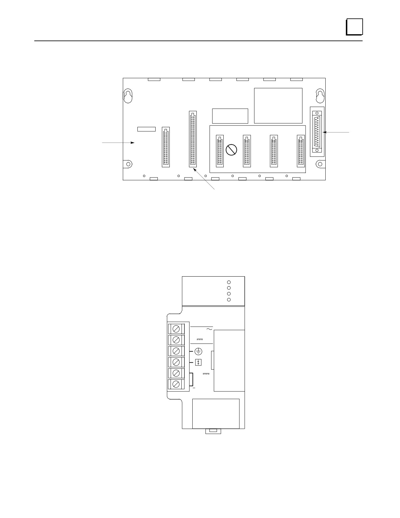
We’ll start with the baseplate. To keep it simple, we’ll use a 5-slot size. Note that a 5-slot
baseplate actually has six slots, but the power supply slot is not numbered. Note also,
that this baseplate has a CPU slot, which is slot number 1, and it has an expansion
connector on the right end, which is used for connecting to another baseplate if the
system has more than one baseplate.
1-2
Series 90-30 PLC Installation and Hardware Manual - October 1999
GFK-0356P
1
a44564
PROGRAMMABLE
CONTROLLER
BASE 5-SLOT
E
X
P
A
CAUTION
NON-CPU SLOTS
N
USER PROGRAM
S
I/O Bus
Memory Backup
AND REGISTER
I
Expansion
VALUES MAY BE
Warning Label
O
LOST IF POWER
Connector
SUPPLY IS
N
REMOVED FOR
CP
LONGER THAN
U
1 HOUR
CPU/1
I/O-2
I/O-3
I/O-4
I/O-5
POWER
SUPPLY
CPU Slot (Slot 1)
Figure 1-1. Five-Slot CPU Baseplate
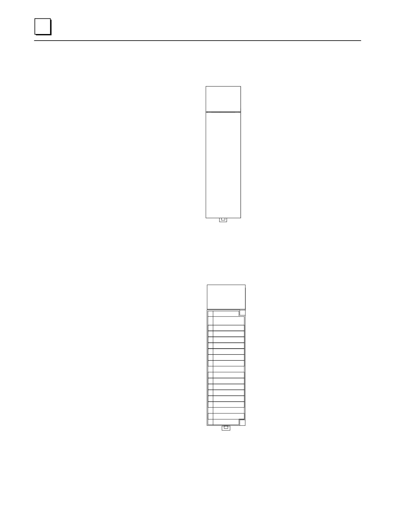
Next, we’ll add a power supply module. It mounts in the unnumbered slot on the left
end of the baseplate. This slot has a unique connector that will only fit a power supply
module.
a45625A
PWR
GE Fanuc
OK
Series 90-30
RUN
BATT
HIGH CAPACITY
POWER SUPPLY
PROGRAMMABLE CONTROLLER
INPUT
100-240 VAC
50/60 HZ 100VA
125VDC, 50W
+
24 VDC
OUTPUT
0.8A MAX.
B
A
T
T
E
R
Y
Figure 1-2. Power Supply Module
GFK-0356P
Chapter 1 Overview of the Series 90-30 PLC
1-3
1
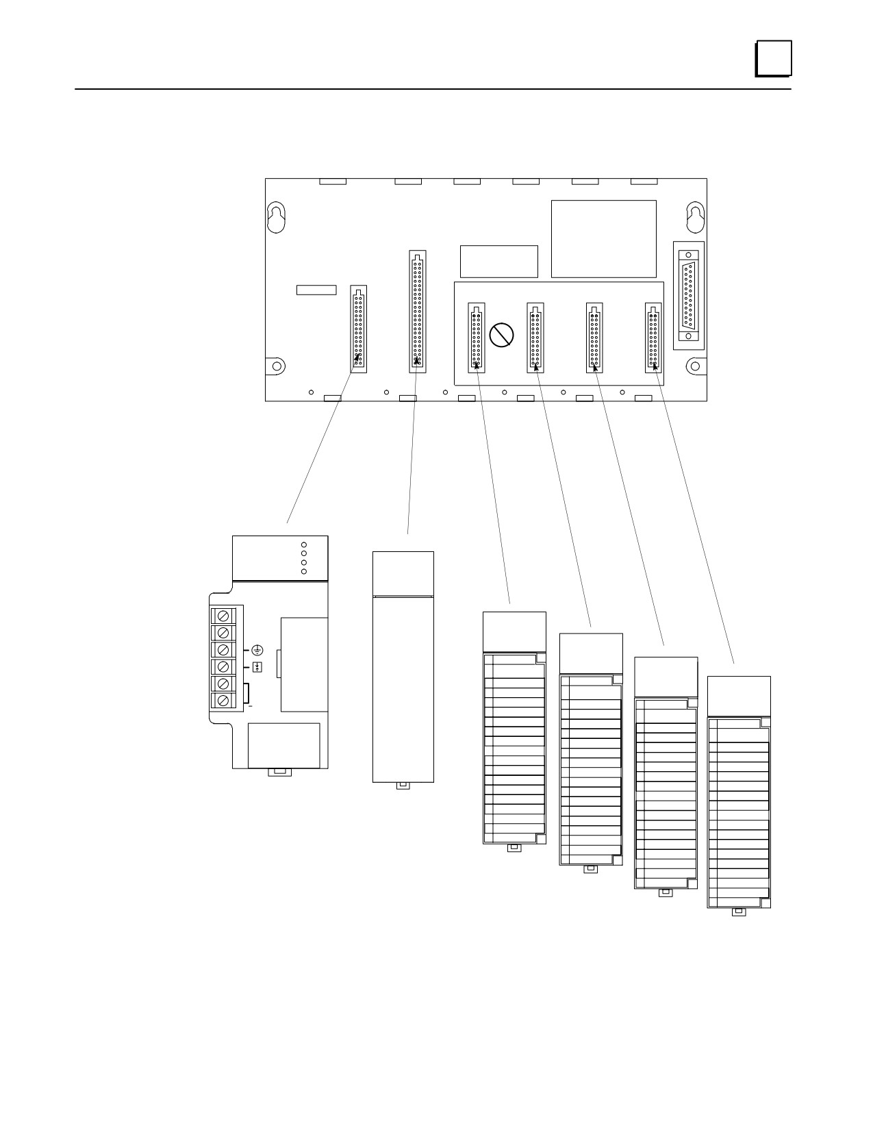
Then, a CPU module. A CPU module can only mount in baseplate slot 1, next to the
power supply. Slot 1 has a unique connector that will only fit CPU or special Option
modules.
ÎÎÎÎ
CPU340
ÎÎÎÎ
ÎÎÎÎ
ÎÎÎÎ
ÎÎÎÎ
ÎÎÎÎ
ÎÎÎÎ
ÎÎÎÎ
ÎÎÎÎ
ÎÎÎÎ
ÎÎÎÎ
ÎÎÎÎ
ÎÎÎÎ
ÎÎÎÎ
Figure 1-3. CPU Module
To finish, we will add some I/O modules to baseplate slots 2 through 5.
A1 2 3 4 5 6 7 8
F
B1 2 3 4 5 6 7 8
ÎÎÎÎ
ÎÎxxx xxx xx
Î
A2
ÎA1ÎÎÎÎ
ÎA3ÎÎÎÎ
A4
Î
ÎA5ÎÎÎ
A7
ÎA6ÎÎÎÎ
B1
ÎA8ÎÎÎÎ
ÎB2ÎÎÎÎ
ÎB4ÎÎÎÎ
B6
ÎB5ÎÎÎÎ
Î
ÎB7ÎÎÎ
B8
Î
ÎÎÎÎ
ÎÎÎÎ
Figure 1-4. I/O Module
1-4
Series 90-30 PLC Installation and Hardware Manual - October 1999
GFK-0356P
1
a44564A
PROGRAMMABLE
CONTROLLER
BASE 5-SLOT
E
X
P
A
CAUTION
NON-CPU SLOTS
N
USER PROGRAM
S
AND REGISTER
I
VALUES MAY BE
LOST IF POWER
O
SUPPLY IS
N
REMOVED FOR
CP
LONGER THAN
U
1 HOUR
CPU/1
I/O-2
I/O-3
I/O-4
I/O-5
POWER
SUPPLY
PWR
GE Fanuc
OK
ÎÎÎÎ
Series 90-30
RUN
CPU340
BATT
ÎÎÎÎ
HIgh Capacity
Power Supply
ÎÎÎ
Î
ÎÎÎÎ
A1 2 3 4 5 6 7 8
F
B1 2 3 4 5 6 7 8
ÎÎÎÎ
A1 2 3 4 5 6 7 8
F
B1 2 3 4 5 6 7 8
ÎÎÎÎ
ÎÎÎ
xxxxxx
Î
A1 2 3 4 5 6 7 8
F
B1 2 3 4 5 6 7 8
+
ÎÎÎÎ
Î
A1Îxxx xxx xx
ÎÎÎÎ
xxxxxx
Î
A2
A1 2 3 4 5 6 7 8
xxx xxx xx
F
B1 2 3 4 5 6 7 8
ÎÎÎÎ
Î
A3ÎÎÎÎÎÎA1
ÎÎÎÎ
A4
A2
xxxxxx
xxx xxx xx
A3
ÎÎÎÎ
Î
A6
A5ÎÎÎÎÎÎÎ
A1
ÎÎÎ
xxxxxx
Î
A4
A2
xxx xxx xx
A3
ÎÎÎÎ
Î
A8ÎÎ
Î
A5ÎÎÎA6
ÎÎÎÎÎÎÎA1
B1
A4
A2
A5
ÎÎÎÎ
ÎÎÎÎ
A7ÎÎÎA8
Î
A6
ÎÎÎ
A4
A3ÎÎÎ
B3
A7
ÎÎÎÎ
Î
B5
B4ÎÎÎ
B1ÎÎÎB2
Î
A8
ÎÎÎ
ÎÎÎA6
B3
Power Supply
B1
B2
ÎÎÎA8
CPU
Î
B7ÎÎ
ÎÎÎÎB4
B5
ÎÎÎÎ
B3
B1
B4
Î
B8ÎÎÎ
B6ÎÎÎB7
Î
B5
ÎÎÎ
B3
B2ÎÎÎ
B8
B6
ÎÎÎÎ
Î
B7
ÎÎÎ
ÎÎÎB5
B8
Î
Î
ÎÎ
ÎÎÎB7
B8
ÎÎÎÎ
I/O Modules
Figure 1-5. Assembling the System
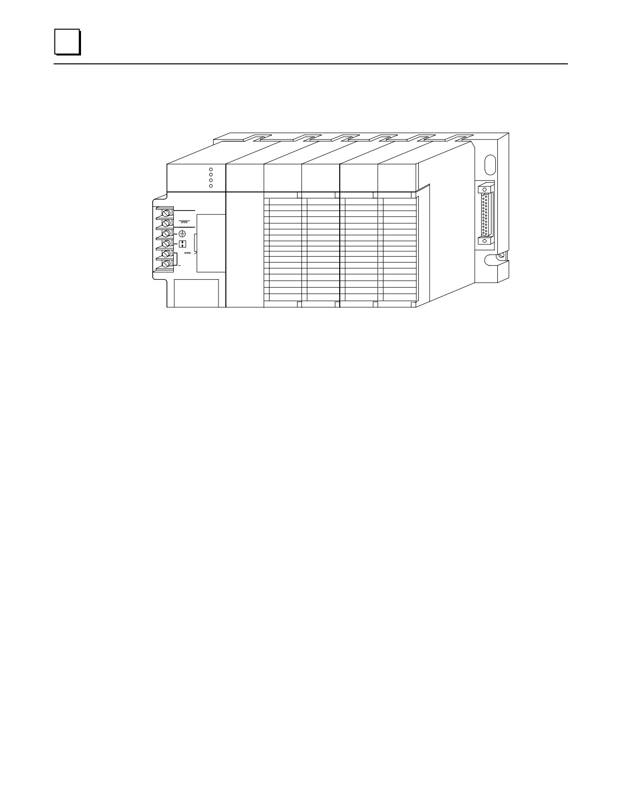
When assembled, the system will look like ...
GFK-0356P
Chapter 1 Overview of the Series 90-30 PLC
1-5
1
this:
a45616A
PWR
CPU
GE Fanuc
OK
A 1 2 3 4 5 6 7 8
A 1 2 3 4 5 6 7 8
A 1 2 3 4 5 6 7 8
A 1 2 3 4 5 6 7 8
F
F
F
F
SERIES 90-30
RUN
B 1 2 3 4 5 6 7 8
B 1 2 3 4 5 6 7 8
B 1 2 3 4 5 6 7 8
B 1 2 3 4 5 6 7 8
BATT
HIGH CAPACITY
POWER SUPPLY
PROGRAMMABLECONTROLLER
INPUT
100-240 ~C
50/60HZ 100VA
125 VDC, 50W
+
24 VDC
OUTPUT
0.8A MAX.
B
A
T
T
E
R
Y
Figure 1-6. A Basic System
An assembly of baseplate and modules such as this one is called a “Rack.”
What else would be needed to make this basic system functional?
To make this basic system functional, you would need:
Mounting. Safe, secure mounting for the PLC, preferably in a protective enclosure.
Wiring. This includes properly installed incoming power to the power supply, as
well as wiring from the I/O modules to field devices such as switches, sensors,
solenoids, relays, etc.
Program. An application program for the PLC to run. This is developed with GE
Fanuc PLC programming software.
What if the application requires more than five modules?
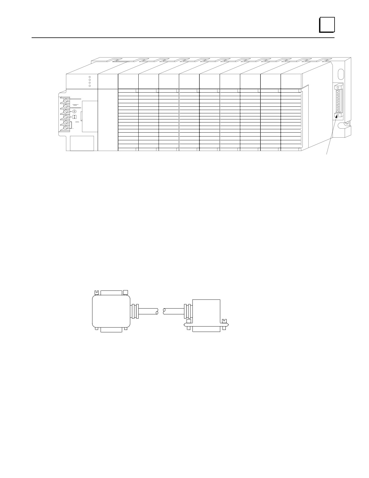
You could use a 10-slot baseplate, shown in the next picture:
1-6
Series 90-30 PLC Installation and Hardware Manual - October 1999
GFK-0356P
1
a45617
PWR
CPU
GE Fanuc
OK
A 1 2 3 4 5 6 7 8
A 1 2 3 4 5 6 7 8
A 1 2 3 4 5 6 7 8
A 1 2 3 4 5 6 7 8
A 1 2 3 4 5 6 7 8
A 1 2 3 4 5 6 7 8
A 1 2 3 4 5 6 7 8
A 1 2 3 4 5 6 7 8
A 1 2 3 4 5 6 7 8
F
F
F
F
F
F
F
F
F
SERIES 90-30
RUN
B 1 2 3 4 5 6 7 8
B 1 2 3 4 5 6 7 8
B 1 2 3 4 5 6 7 8
B 1 2 3 4 5 6 7 8
B 1 2 3 4 5 6 7 8
B 1 2 3 4 5 6 7 8
B 1 2 3 4 5 6 7 8
B 1 2 3 4 5 6 7 8
B 1 2 3 4 5 6 7 8
BATT
HIGH CAPACITY
POWER SUPPLY
PROGRAMMABLE CONTROLLER
INPUT
~
100-240 VAC
50/60HZ 100VA
125 VDC, 50W
+ 24 VDC
OUTPUT
0.8A MAX.
B
A
T
T
E
R
Y
I/O Bus Expansion Connector
Figure 1-7. Ten-Slot Rack
What if the application requires more than ten modules?
You can add one or more Expansion or Remote racks to this system. Some CPUs can
support up to seven additional racks. If you added seven additional 10-slot racks, you
could have 70 more modules.
Racks are interconnected in a ”daisy-chain” cabling arrangement. This interconnection
system is called the ”I/O Expansion Bus.” The connections are made from one
baseplate’s I/O Bus Expansion Connector (shown in the figure above) to the next one’s.
The I/O Bus Expansion Cables, shown below, have a double connector on one end to
facilitate these connections.
FEMALE
CONNECTOR
ÎÎ Î
Î
Î
ÎÎ
Î
ÎÎ
ÎÎ
ÎÎ Î
MALE
MALE
CONNECTOR
CONNECTOR
Figure 1-8. I/O Bus Expansion Cable
GFK-0356P
Chapter 1 Overview of the Series 90-30 PLC
1-7
1
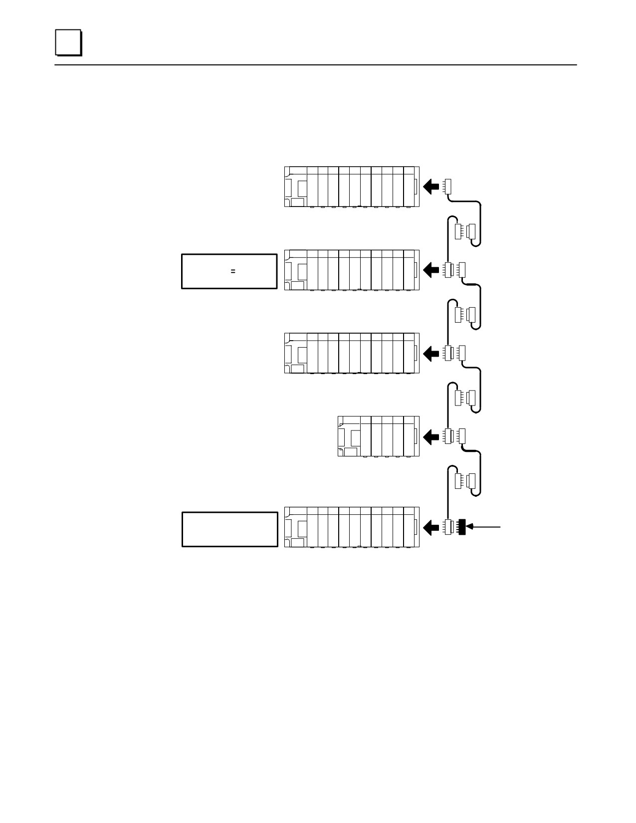
The next figure shows a system that has a CPU baseplate, one Expansion rack and three
Remote racks. Notice that the last rack, the one at the end of the I/O Expansion Bus,
must be terminated. A convenient way of terminating the bus is with an IC693ACC307
I/O Bus Terminator Plug, as shown.
CPU BASEPLATE
a44965A
CPU
C
BASEPLATE
P
U
EXPANSION
BASEPLATE
EXPANSION BASEPLATE
MAXIMUM DISTANCE
FROM CPU 50 FEET
(15 METERS)
REMOTE BASEPLATE
REMOTE
BASEPLATE
REMOTE BASEPLATE
REMOTE
BASEPLATE
ÎÎÎ
ÎÎÎ
ÎÎ
REMOTE
BASEPLATE
REMOTE BASEPLATE
I/O BUS
MAXIMUM DISTANCE
TERMINATOR
FROM CPU= 700 FEET
PLUG
(213 METERS)
IC693ACC307
Figure 1-9. Connecting Expansion and Remote Baseplates
What is the Difference Between Expansion and Remote baseplates?
The main factor to consider is distance. How far will the baseplate be from the CPU
baseplate? If the cabling distance from the CPU baseplate is 50 feet (15 meters) or less,
use an Expansion baseplate. The Expansion baseplate is preferable because of its higher
communication speed with the CPU baseplate. However, if a baseplate must be located
where it requires a cabling distance from the CPU rack in excess of 50 feet, an Expansion
baseplate will not work - a Remote baseplate must be used. The limit for a Remote
baseplate is a cabling distance of 700 feet (213 meters) from the CPU baseplate to the
farthest Remote baseplate.
1-8
Series 90-30 PLC Installation and Hardware Manual - October 1999
GFK-0356P