FANUC Series 30i-MODEL B, 31i-MODEL B, 32i-MODEL B. For Machining Center System. OPERATOR'S MANUAL - page 15
B-64484EN-2/02
APPENDIX
A.PARAMETERS
#4 DOV Override during extraction in rigid tapping:
0: Invalidated
1: Validated
(The override value is set in parameter No.
5211. However, set an
override value for rigid tapping return in parameter No. 5381.)
#5 PCP Rigid tapping:
0: Used as a high-speed peck tapping cycle
1: Not used as a high-speed peck tapping cycle
#6 FHD Feed hold and single block in rigid tapping:
0: Invalidated
1: Validated
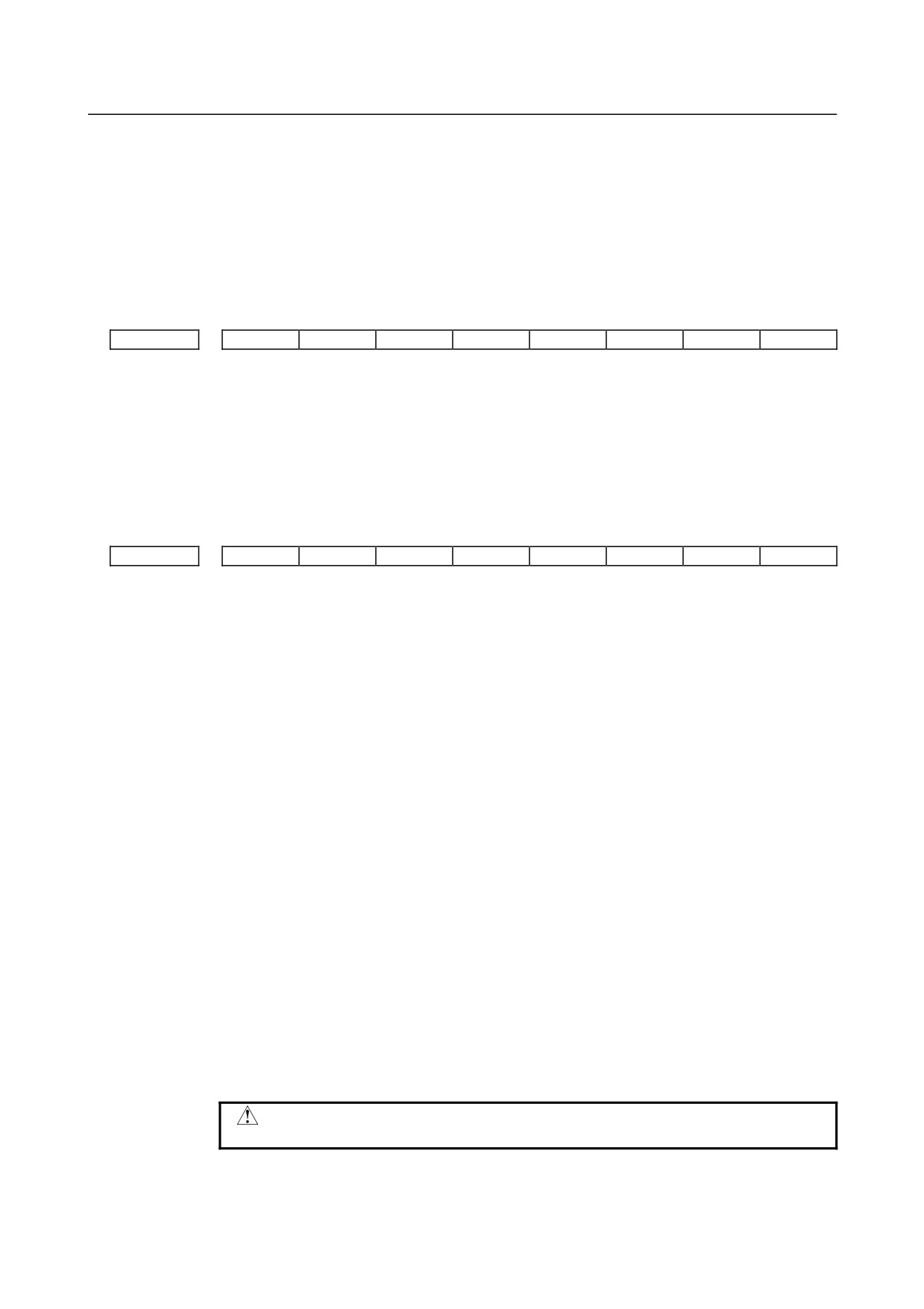
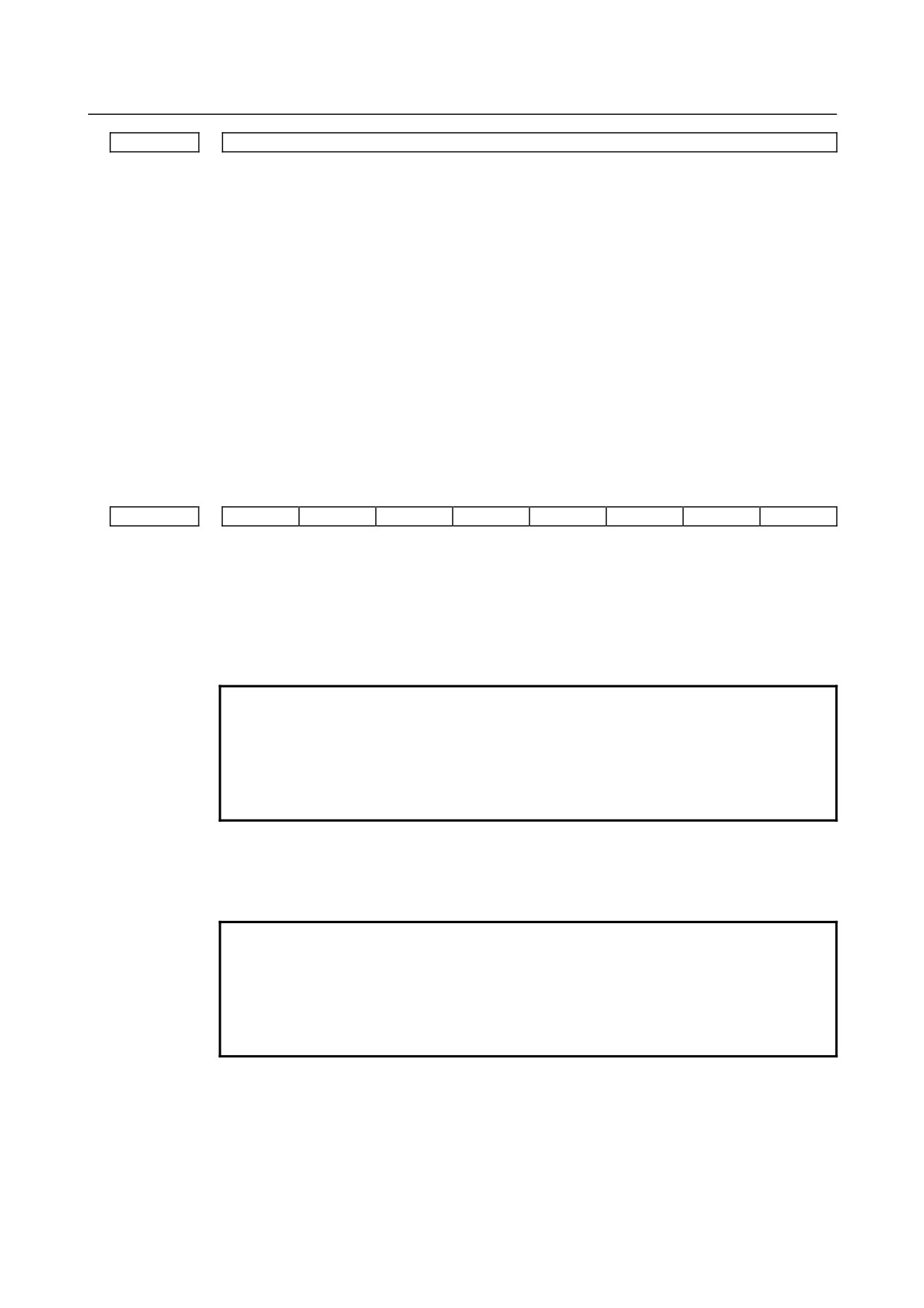
#7
#6
#5
#4
#3
#2
#1
#0
5201
OV3
OVU
[Input type] Parameter input
[Data type] Bit path
#3 OVU The increment unit of the override parameter No. 5211 for tool rigid tapping extraction is:
0:
1%
1:
10%
#4 OV3 A spindle speed for extraction is programmed, so override for extraction operation is:
0: Disabled.
1: Enabled.
#7
#6
#5
#4
#3
#2
#1
#0
5203
OVS
[Input type] Parameter input
[Data type] Bit path
#4 OVS In rigid tapping, override by the feedrate override select signal and cancellation of
override by the override cancel signal is:
0: Disabled.
1: Enabled.
When feedrate override is enabled, extraction override is disabled.
The spindle override is clamped to 100% during rigid tapping, regardless of the setting of
this parameter.
5211
Override value during rigid tapping extraction
[Input type] Parameter input
[Data type] Word path
[Unit of data] 1% or 10%
[Valid data range] 0 to 200
The parameter sets the override value during rigid tapping extraction.
- 417 -
A.PARAMETERS
APPENDIX
B-64484EN-2/02
NOTE
The override value is valid when bit 4 (DOV) of parameter No. 5200
is set to 1. When bit 3 (OVU) of parameter No. 5201 is set to 1, the
unit of set data is 10%. An override of up to 200% can be applied to
extraction.
5213
Return in peck rigid tapping cycle
[Input type] Setting input
[Data type] Real path
[Unit of data] mm, inch (input unit)
[Min. unit of data] Depend on the increment system of the drilling axis
[Valid data range] 0 or positive 9 digit of minimum unit of data (refer to the standard parameter setting table
(B))
(When the increment system is IS-B, 0.0 to +999999.999)
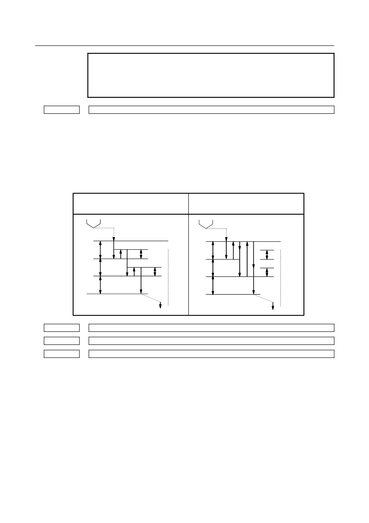
This parameter sets the return or clearance in the peck tapping cycle.
When the parameter PCP (bit 5 of No.5200) is
When the parameter PCP (bit 5 of No.5200)
set to 0.
is set to 1.
q : Depth of cut
q : Depth of cut
d : Return value
d : Clearance value
R point
R point
q
q
d
d
q
q
d
d
q
q
Z point
Z point
5241
Maximum spindle speed in rigid tapping (first gear)
5242
Maximum spindle speed in rigid tapping (second gear)
5243
Maximum spindle speed in rigid tapping (third gear)
[Input type] Parameter input
[Data type] 2-word spindle
[Unit of data] min-1
[Valid data range] 0 to 9999
Spindle position coder gear ratio
1 : 1
0 to 7400
1 : 2
0 to 9999
1 : 4
0 to 9999
1 : 8
0 to 9999
Each of these parameters is used to set a maximum spindle speed for each gear in rigid
tapping.
Set the same value for both parameter No. 5241 and parameter No. 5243 for a one-stage
gear system. For a two-stage gear system, set the same value as set in parameter No. 5242
in parameter No. 5243. Otherwise, alarm PS0200, “ILLEGAL S CODE COMMAND”
will be issued. This applies to the M series.
- 418 -
B-64484EN-2/02
APPENDIX
A.PARAMETERS
5321
Spindle backlash in rigid tapping (first-stage gear)
5322
Spindle backlash in rigid tapping (second-stage gear)
5323
Spindle backlash in rigid tapping (third-stage gear)
[Input type] Parameter input
[Data type] Word spindle
[Unit of data] Detection unit
[Valid data range] -9999 to 9999
Each of these parameters is used to set a spindle backlash.
#7
#6
#5
#4
#3
#2
#1
#0
5400
RIN
[Input type] Parameter input
[Data type] Bit path
#0 RIN Coordinate rotation angle command (R) :
0: Specified by an absolute method
1: Specified by an absolute method (G90) or incremental method (G91)
5410
Angular displacement used when no angular displacement is specified for coordinate system rotation
[Input type] Setting input
[Data type] 2-word path
[Unit of data] 0.001 degree
[Valid data range] -360000 to 360000
This parameter sets the angular displacement for coordinate system rotation. When the
angular displacement for coordinate system rotation is not specified with address R in the
block where G68 is specified, the setting of this parameter is used as the angular
displacement for coordinate system rotation.
#7
#6
#5
#4
#3
#2
#1
#0
5431
MDL
[Input type] Parameter input
[Data type] Bit path
NOTE
When this parameter is set, the power must be turned off before
operation is continued.
#0 MDL The G60 code (single direction positioning) is:
0: One-shot G code (group 00).
1: Modal G code (group 01).
5480
Number of the axis for controlling the normal direction
[Input type] Parameter input
[Data type] Byte path
[Valid data range] 1 to the maximum controlled axis number
This parameter sets the controlled axis number of the axis for controlling the normal
direction.
- 419 -
A.PARAMETERS
APPENDIX
B-64484EN-2/02
5481
Feedrate of rotation of the normal direction controlled axis
[Input type] Parameter input
[Data type] Real axis
[Unit of data] deg/min
[Min. unit of data] Depend on the increment system of the applied axis
[Valid data range] Refer to the standard parameter setting table (C)
This parameter sets the feedrate of the movement along the normal direction controlled
axis that is inserted at the start point of a block during normal direction control.
Limit value used to determine whether to ignore the rotation insertion of the normal direction
5482
controlled axis
[Input type] Parameter input
[Data type] Real path
[Unit of data] Degree
[Min. unit of data] Depend on the increment system of the reference axis
[Valid data range] 0 or positive 9 digit of minimum unit of data (refer to the standard parameter setting table
(B))
The rotation block of the normal direction controlled axis is not inserted when the
rotation insertion angle calculated during normal direction control does not exceed this
setting.
The ignored rotation angle is added to the next rotation insertion angle, and the block
insertion is then judged.
NOTE
1 No rotation block is inserted when 360 or more degrees are set.
2 If 180 or more degrees are set, a rotation block is inserted only
when the circular interpolation setting is 180 or more degrees.
#7
#6
#5
#4
#3
#2
#1
#0
5484
SDC
[Input type] Parameter input
[Data type] Bit path
#0 SDC Gentle normal direction control function is:
0: Disabled.
1: Enabled.
5485
Limit for single-block rotation by the gentle normal direction control function
[Input type] Parameter input
[Data type] Real path
[Unit of data] degree
[Min. unit of data] Depend on the increment system of the reference axis
[Valid data range] 0 to 360
This parameter is valid when bit 0 (SDC) of parameter No. 5484 is set to 1.
Gentle normal direction control rotates a normal direction control axis simultaneously
with an X/Y-axis move block when the calculated rotation insertion angle is smaller than
this parameter setting. If it is greater than the setting, the normal direction control axis is
rotated with a single block.
- 420 -
B-64484EN-2/02
APPENDIX
A.PARAMETERS
NOTE
1 This parameter is valid only when the normal direction control axis
is rotated according to the settings of parameters No. 5482 and No.
5483.
2 If this parameter is set to 360 or greater, the setting is assumed to
be 360, and the normal direction control axis is rotated
simultaneously with the X/Y-axis move block.
3 If this parameter is set to 180 or greater, the normal direction
control axis is rotated simultaneously with the X/Y-axis move block
unless circular interpolation is used.
4 If this parameter is set to a negative value, the setting is assumed
to be 0, and the normal direction control axis is rotated with the
single block.
5486
Block distance to move until the end of rotation of the normal direction control axis
[Input type] Parameter input
[Data type] Real path
[Unit of data] mm, inch (input unit)
[Min. unit of data] Depend on the increment system of the reference axis
[Valid data range] 0 or positive 9 digit of minimum unit of data
This parameter sets the command block distance to move until the rotation of the normal
direction control axis is completed. When 0 is specified, this function is disabled.
#7
#6
#5
#4
#3
#2
#1
#0
5500
SIM
G90
INC
ABS
REL
[Input type] Parameter input
[Data type] Bit path
#1 REL The position display of the index table indexing axis in the relative coordinate system is:
0: Not rounded by one rotation.
1: Rounded by one rotation.
#2 ABS The position display of the index table indexing axis in the absolute coordinate system is:
0: Not rounded by one rotation.
1: Rounded by one rotation.
#3 INC When the M code that specifies rotation in the negative direction (parameter No. 5511) is
not set, rotation in the G90 mode is:
0: Not set to the shorter way around the circumference.
1: Set to the shorter way around the circumference.
#4 G90 A command for the index table indexing axis is:
0: Assumed to be an absolute or incremental programming according to the mode.
1: Always assumed to be an absolute programming.
#6 SIM When the same block includes a command for the index table indexing axis and a
command for another controlled axis:
0: The setting of bit 0 (IXS) of parameter No. 5502 is followed.
1: The commands are executed.
- 421 -
A.PARAMETERS
APPENDIX
B-64484EN-2/02
NOTE
Even when this parameter is set to 1, an alarm PS1564, “INDEX
TABLE AXIS - OTHER AXIS SAME TIME” is issued if the block is
neither G00, G28, nor G30 (or the G00 mode).
#7
#6
#5
#4
#3
#2
#1
#0
5501
ITI
[Input type] Parameter input
[Data type] Bit path
#0 ITI The index table indexing function is:
0: Enabled.
1: Disabled.
#7
#6
#5
#4
#3
#2
#1
#0
5502
IXS
[Input type] Parameter input
[Data type] Bit axis
#0 IXSx When a command is specified in a block that contains a command for the index table
indexing axis:
0 : An alarm PS1564, “INDEX TABLE AXIS - OTHER AXIS SAME TIME” is
issued.
1 : The command is executed.
If bit 6 (SIM) of parameter No. 5500 is set to 1, a simultaneous operation with all axes
except the index table indexing axis can be performed regardless of the setting of this
parameter.
To set an axis that allows simultaneous operation for each axis, set SIM to 0, and set this
parameter.
NOTE
Even when this parameter is set to 1, an alarm PS1564, “INDEX
TABLE AXIS - OTHER AXIS SAME TIME” is issued if the block is
neither G00, G28, nor G30 (or the G00 mode).
5511
M code that specifies rotation in the negative direction for index table indexing
[Input type] Parameter input
[Data type] 2-word path
[Valid data range] 0 to 99999999
0: The rotation direction for the index table indexing axis is determined according to
the setting of bit 3 (INC) of parameter No. 5500 and a command.
1 to 99999999:
The rotation for the index table indexing axis is always performed in the positive
direction. It is performed in the negative direction only when a move command is
specified together with the M code set in this parameter.
NOTE
Be sure to set bit 2 (ABS) of parameter No. 5500 to 1.
- 422 -
B-64484EN-2/02
APPENDIX
A.PARAMETERS
5512
Minimum positioning angle for the index table indexing axis
[Input type] Parameter input
[Data type] Real path
[Unit of data] deg
[Min. unit of data] Depend on the increment system of the reference axis
[Valid data range] 9 digit of minimum unit of data (refer to standard parameter setting table (A))
(When the increment system is IS-B, -999999.999 to +999999.999)
This parameter sets the minimum positioning angle (travel distance) for the index table
indexing axis. The travel distance specified in the positioning command must always be
an integer multiple of this setting. When 0 is set, the travel distance is not checked.
The minimum positioning angle is checked not only for the command, but also for the
coordinate system setting and workpiece origin offset.
5610
Limit of initial permissible error during involute interpolation
[Input type] Parameter input
[Data type] Real path
[Unit of data] mm, inch (input unit)
[Min. unit of data] Depend on the increment system of the reference axis
[Valid data range] 0 or positive 9 digit of minimum unit of data (refer to the standard parameter setting table
(B))
(When the increment system is IS-B, 0.0 to +999999.999)
This parameter sets the allowable limit of deviation between an involute curve passing
through a start point and an involute curve passing through an end point for an involute
interpolation command.
5620
Lower override limit in automatic feedrate control during involute interpolation
[Input type] Parameter input
[Data type] Byte path
[Unit of data] %
[Valid data range] 0 to 100
In "override in the cutter compensation mode" under involute interpolation automatic
feedrate control, the feedrate of the tool center near a basic circle may become very low
in the case of an inner offset. To prevent this, set a lower override limit in this parameter.
Thus, the feedrate is clamped so that the feedrate is not lower than a specified feedrate
multiplied by the lower override limit set in this parameter.
NOTE
When 0 or a value not within the valid data range is set, involute
interpolation automatic feedrate control ("override in the cutter
compensation mode" and "acceleration clamping near a basic
circle") is disabled.
#7
#6
#5
#4
#3
#2
#1
#0
6000
HGO
MGO
[Input type] Parameter input
[Data type] Bit path
- 423 -
A.PARAMETERS
APPENDIX
B-64484EN-2/02
#1 MGO When a GOTO statement for specifying custom macro control is executed, a high-speed
branch to 20 sequence numbers executed from the start of the program is:
0: A high-speed branch is not caused to n sequence numbers from the start of the
executed program.
1: A high-speed branch is caused to n sequence numbers from the start of the program.
#4 HGO When a GOTO statement in a custom macro control command is executed, a high-speed
branch to the 30 sequence numbers immediately before the executed statement is:
0: Not made.
1: Made.
#7
#6
#5
#4
#3
#2
#1
#0
6210
MDC
[Input type] Parameter input
[Data type] Bit path
#6 MDC The measurement result of automatic tool length measurement is:
0: Added to the current offset.
1: Subtracted from the current offset.
6241
Feedrate during measurement of automatic tool length measurement (for the XAE1 and GAE1 signals)
6242
Feedrate during measurement of automatic tool length measurement (for the XAE2 and GAE2 signals)
6243
Feedrate during measurement of automatic tool length measurement (for the XAE3 and GAE3 signals)
[Input type] Parameter input
[Data type] Real path
[Unit of data] mm/min, inch/min, deg/min (machine unit)
[Min. unit of data] Depend on the increment system of the applied axis
[Valid data range] Refer to the standard parameter setting table (C)
(When the increment system is IS-B, 0.0 to +999000.0)
These parameters set the relevant feedrate during measurement of automatic tool length
measurement.
NOTE
When the setting of parameter No. 6242 or 6243 is 0, the setting of
parameter No. 6241 is used.
6251
γ value during automatic tool length measurement (for the XAE1 and GAE1 signals)
6252
γ value during automatic tool length measurement (for the XAE2 and GAE2 signals)
6253
γ value during automatic tool length measurement (for the XAE3 and GAE3 signals)
[Input type] Parameter input
[Data type] 2-word path
[Unit of data] mm, inch, deg (machine unit)
[Min. unit of data] Depend on the increment system of the applied axis
[Valid data range] 9 digit of minimum unit of data (refer to standard parameter setting table (A))
(When the increment system is IS-B, -999999.999 to +999999.999)
These parameters set the relevant γ value during automatic tool length measurement.
- 424 -
B-64484EN-2/02
APPENDIX
A.PARAMETERS
NOTE
1 When the setting of parameter No. 6252 or 6253 is 0, the setting of
parameter No. 6251 is used.
2 Set a radius value regardless of whether diameter or radius
programming is specified.
6254
ε value during automatic tool length measurement (for the XAE1 and GAE1 signals)
6255
ε value during automatic tool length measurement (for the XAE2 and GAE2 signals)
6256
ε value during automatic tool length measurement (for the XAE3 and GAE3 signals)
[Input type] Parameter input
[Data type] 2-word path
[Unit of data] mm, inch, deg (machine unit)
[Min. unit of data] Depend on the increment system of the applied axis
[Valid data range] 9 digit of minimum unit of data (refer to standard parameter setting table (A))
(When the increment system is IS-B, -999999.999 to +999999.999)
These parameters set the relevant ε value during automatic tool length measurement.
NOTE
1 When the setting of parameter No. 6252 or 6253 is 0, the setting of
parameter No. 6251 is used.
2 Set a radius value regardless of whether diameter or radius
programming is specified.
#7
#6
#5
#4
#3
#2
#1
#0
7001
ABS
[Input type] Parameter input
[Data type] Bit path
#1 ABS For the move command after manual intervention in the manual absolute on state:
0: Different paths are used in the absolute (G90) and incremental (G91) modes.
1: The same path (path in the absolute mode) is used in the absolute (G90) and
incremental (G91) modes.
#7
#6
#5
#4
#3
#2
#1
#0
7570
CFA
FTP
[Input type] Parameter input
[Data type] Bit path
#0 FTP Fixture offset type setting
0: Movement type (The tool moves when the fixture offset changes.)
1: Shift type (The tool does not move when the fixture offset changes.)
- 425 -
A.PARAMETERS
APPENDIX
B-64484EN-2/02
#3 CFA When the fixture offset function is used, and a rotation axis is specified in the increment
mode (G91 mode) after manual intervention in the state where the manual absolute switch
is on:
0: A vector calculation is made using coordinates not reflecting a manual intervention
amount.
1: A vector calculation is made using coordinates reflecting a manual intervention
amount.
#7
#6
#5
#4
#3
#2
#1
#0
7575
FAX
[Input type] Parameter input
[Data type] Bit axis
#0 FAX Fixture offset on each axis is:
0: Disabled.
1: Enabled.
7580
Rotation axis for fixture offset (first group)
7581
Linear axis 1 for fixture offset (first group)
7582
Linear axis 2 for fixture offset (first group)
7583
Rotation axis for fixture offset (second group)
7584
Linear axis 1 for fixture offset (second group)
7585
Linear axis 2 for fixture offset (second group)
7586
Rotation axis for fixture offset (third group)
7587
Linear axis 1 for fixture offset (third group)
7588
Linear axis 2 for fixture offset (third group)
[Input type] Parameter input
[Data type] Byte path
[Valid data range] 0 to Number of controlled axes
These parameters specify rotation axes for fixture offset and pairs of
linear axes for
selecting a rotation plane. Specify a pair of linear axes so that rotation from the positive
direction of linear axis 1 to the positive direction is in the normal direction of the rotation
axis.
Up to three groups of a rotation axis setting and two linear axis settings can be specified.
The fixture offset value is calculated first for the rotation axis in the first group. Then, for
the second and third groups, the fixture value is sequentially calculated using the previous
calculation result. When you do not need the third group, set 0 for the rotation axis.
#7
#6
#5
#4
#3
#2
#1
#0
8360
ROV
[Input type] Setting input
[Data type] Bit path
- 426 -

B-64484EN-2/02
APPENDIX
A.PARAMETERS
#0 ROV As rapid traverse override for a section from the chopping start point to point R:
0: Chopping override is used.
1: Rapid traverse override is used.
8370
Chopping axis
[Input type] Parameter input
[Data type] Byte path
[Valid data range] 1 to Number of controlled axes
This parameter sets which servo axis the chopping axis corresponds to.
8371
Chopping reference point (point R)
[Input type] Parameter input
[Data type] Real path
[Unit of data] mm, inch, deg (input unit)
[Min. unit of data] Depend on the increment system of the chopping axis
[Valid data range] 9 digit of minimum unit of data (refer to standard parameter setting table (A))
(When the increment system is IS-B, -999999.999 to +999999.999)
The data set in this parameter is absolute coordinates.
8372
Chopping upper dead point
[Input type] Parameter input
[Data type] Real path
[Unit of data] mm, inch, deg (input unit)
[Min. unit of data] Depend on the increment system of the chopping axis
[Valid data range] 9 digit of minimum unit of data (refer to standard parameter setting table (A))
(When the increment system is IS-B, -999999.999 to +999999.999)
The data set in this parameter is absolute coordinates.
8373
Chopping lower dead point
[Input type] Parameter input
[Data type] Real path
[Unit of data] mm, inch, deg (input unit)
[Min. unit of data] Depend on the increment system of the chopping axis
[Valid data range] 9 digit of minimum unit of data (refer to standard parameter setting table (A))
(When the increment system is IS-B, -999999.999 to +999999.999)
The data set in this parameter is absolute coordinates.
8374
Chopping feedrate
[Input type] Parameter input
[Data type] Real path
[Unit of data] mm/min, inch/min, deg/min (input unit)
[Min. unit of data] Depend on the increment system of the chopping axis
[Valid data range] Refer to the standard parameter setting table (C)
(When the increment system is IS-B, 0.0 to +999000.0)
This parameter sets the chopping feedrate.
8375
Maximum chopping feedrate
[Input type] Parameter input
[Data type] Real axis
- 427 -
A.PARAMETERS
APPENDIX
B-64484EN-2/02
[Unit of data] mm/min, inch/min, deg/min (machine unit)
[Min. unit of data] Depend on the increment system of the applied axis
[Valid data range] Refer to the standard parameter setting table (C)
(When the increment system is IS-B, 0.0 to +999000.0)
The chopping feedrate is clamped at this parameter setting. The maximum feedrate must
be set for the chopping axis. If this parameter is set to 0, no movement is made for
chopping.
NOTE
Please set a value that is smaller than the normal rapid traverse
rate (parameter No. 1420) to Maximum chopping feedrate.
8376
Chopping compensation factor
[Input type] Parameter input
[Data type] Byte path
[Unit of data] %
[Valid data range] 0 to 100
The value obtained by multiply the sum of the servo delay in an chopping operation and
the acceleration/deceleration delay by the rate set in this parameter is used as chopping
delay compensation. When this parameter is set to 0, chopping delay compensation is not
applied.
8377
Chopping compensation start tolerance
[Input type] Parameter input
[Data type] 2-word path
[Unit of data] Detection unit
[Valid data range] 0 to 99999999
In a chopping operation, compensation is applied when the difference between an amount
of shortage at the upper dead point and that at the lower dead point due to the servo
position control delay is less than the value set in this parameter. When this parameter is
set to 0, compensation is not applied.
10360
Bias value for the offset number of a tool offset for each axis
[Input type] Setting input
[Data type] Word axis
[Valid data range] 0 to the number of tool offsets
When parallel operation is performed, this parameter specifies a bias value for the offset
number of a tool offset for each axis. The offset data to be used as a tool offset for an axis
has a number obtained by adding a value set in this parameter for the axis to a specified
offset number.
10361
Bias for the offset number of tool length compensation for each axis
[Input type] Setting input
[Data type] Word axis
[Valid data range] 0 to the number of tool offsets
When parallel operation is performed, this parameter specifies a bias value for the offset
number of tool length compensation for each axis. The offset data to be used as the tool
length compensation amount for an axis has a number obtained by adding a value set in
this parameter for the axis to a specified offset number.
- 428 -
B-64484EN-2/02
APPENDIX
A.PARAMETERS
#7
#6
#5
#4
#3
#2
#1
#0
10370
RPC
[Input type] Setting input
[Data type] Bit path
#0 RPC When a return from the reference position (G29) is made, axis switching is:
0: Disabled.
1: Enabled.
10371
Axis switching number
[Input type] Setting input
[Data type] Byte path
[Valid data range] 0 to 5
One of six types of axis switching can be selected by setting its axis switching number in
this parameter. Programmed addresses X, Y, and Z correspond to machine axes x, y, and
z as follows:
Programmed address
Axis switching No.
X
Y
Z
0
x
y
z
1
x
z
y
2
y
x
z
3
y
z
x
4
z
x
y
5
z
y
x
Axis switching number 0 indicates that axis switching is not performed.
#7
#6
#5
#4
#3
#2
#1
#0
11400
TOP
[Input type] Parameter input
[Data type] Bit path
#2 TOP Set a tool length compensation or tool offset operation.
0: Tool length compensation or tool offset operation is performed by an axis
movement.
1: Tool length compensation or tool offset operation is performed by shifting the
coordinate system.
NOTE
This parameter is an-individual path parameter having the same
function as bit 6 (TOS) of parameter No. 5006.
To use different compensation types for individual paths, set the
parameter TOS with 0 and specify a compensation type for each
path separately, using the parameter TOP. If the parameter TOS is
1, the parameter TOP is assumed to be 1 even if it is 0.
#7
#6
#5
#4
#3
#2
#1
#0
11600
AX1
[Input type] Parameter input
- 429 -
A.PARAMETERS
APPENDIX
B-64484EN-2/02
[Data type] Bit path
#5 AX1 If, in coordinate system rotation mode, a 1-axis command is issued in absolute mode,
0: First, the specified position is calculated in the coordinate system before rotation,
and then the coordinate system is rotated.
1: First, the coordinate system is rotated, and then the tool moves to the specified
position in the coordinate system.
(FS16i/18i/21i compatible specification)
#7
#6
#5
#4
#3
#2
#1
#0
11630
FRD
[Input type] Parameter input
[Data type] Bit path
#0 FRD The minimum command unit of the rotation angles of coordinate rotation and
3-dimensional coordinate system conversion is:
0:
0.001 degree.
1:
0.00001 degree. (1/100,000)
#7
#6
#5
#4
#3
#2
#1
#0
19607
NAA
CAV
CCC
[Input type] Parameter input
[Data type] Bit path
#2
CCC In the cutter compensation/tool nose radius compensation mode, the outer corner
connection method is based on:
0: Linear connection type.
1: Circular connection type.
#5
CAV When an interference check finds that interference (overcutting) occurred:
0: Machining stops with the alarm PS0041,
“INTERFERENCE IN CUTTER
COMPENSATION”.
(Interference check alarm function)
1: Machining is continued by changing the tool path to prevent interference
(overcutting) from occurring. (Interference check avoidance function)
For the interference check method, see the descriptions of bit 1 (CNC) of parameter No.
5008 and bit 3 (CNV) of parameter No. 5008.
#6
NAA When the interference check avoidance function considers that an avoidance operation is
dangerous or that a further interference to the interference avoidance vector occurs:
0: An alarm is issued.
When an avoidance operation is considered to be dangerous, the alarm PS5447,
“DANGEROUS AVOIDANCE AT G41/G42” is issued.
When a further interference to the interference avoidance vector is considered to
occur, the alarm PS5448, “INTERFERENCE TO AVD. AT G41/G42” is issued.
1: No alarm is issued, and the avoidance operation is continued.
CAUTION
Usually set this parameter to 0.
- 430 -
B-64484EN-2/02
APPENDIX
A.PARAMETERS
19625
Number of blocks to be read in the cutter compensation/tool nose radius compensation mode
[Input type] Setting input
[Data type] Byte path
[Valid data range] 3 to 8
This parameter sets the number of blocks to be read in the cutter compensation/tool nose
radius compensation mode. When a value less than 3 is set, the specification of 3 is
assumed. When a value greater than 8 is set, the specification of 8 is assumed. As a
greater number of blocks are read, an overcutting (interference) forecast can be made with
a command farther ahead. However, the number of blocks read and analyzed increases, so
that a longer block processing time becomes necessary.
Even if the setting of this parameter is modified in the MDI mode by stopping in the
cutter compensation/tool nose radius compensation mode, the setting does not become
valid immediately. Before the new setting of this parameter can become valid, the cutter
compensation/tool noise radius compensation mode must be canceled, then the mode
must be entered again.
#7
#6
#5
#4
#3
#2
#1
#0
25860
NCV
SCV
[Input type] Parameter input
[Data type] Bit path
#2 SCV At power-on, a spindle unit compensation vector is:
0: Not calculated.
1: Calculated.
NOTE
This parameter is effective in the case of either of the following
settings:
• Bit 6 (CLR) of parameter No. 3402 = 0
• Bit 6 (CLR) of parameter No. 3402 = 1 and bit 3 (C27) of
parameter No. 3409 = 1
#3 NCV At power-on, an nutating rotary head tool length compensation vector is:
0: Not calculated.
1: Calculated.
NOTE
This parameter is effective in the case of either of the following
settings:
• Bit 6 (CLR) of parameter No. 3402 = 0
• Bit 6 (CLR) of parameter No. 3402 = 1, bit 0 (C08) of parameter
No. 3407 = 1, and bit 7 (CFH) of parameter No. 3409 = 1
- 431 -

A.PARAMETERS
APPENDIX
B-64484EN-2/02
A.2 DATA TYPE
Parameters are classified by data type as follows:
Data type
Valid data range
Remarks
Bit
Bit machine group
Bit path
0 or 1
Bit axis
Bit spindle
Byte
Byte machine group
-128 to 127
Some parameters handle these types of
Byte path
0 to 255
data as unsigned data.
Byte axis
Byte spindle
Word
Word machine group
-32768 to 32767
Some parameters handle these types of
Word path
0 to 65535
data as unsigned data.
Word axis
Word spindle
2-word
2-word machine group
Some parameters handle these types of
2-word path
0 to ±999999999
data as unsigned data.
2-word axis
2-word spindle
Real
Real machine group
See the Standard Parameter
Real path
Setting Tables.
Real axis
Real spindle
NOTE
1 Each of the parameters of the bit, bit machine group, bit path, bit axis, and bit
spindle types consists of 8 bits for one data number (parameters with eight
different meanings).
2 For machine group types, parameters corresponding to the maximum number of
machine groups are present, so that independent data can be set for each
machine group.
3 For path types, parameters corresponding to the maximum number of paths are
present, so that independent data can be set for each path.
4 For axis types, parameters corresponding to the maximum number of control
axes are present, so that independent data can be set for each control axis.
5 For spindle types, parameters corresponding to the maximum number of
spindles are present, so that independent data can be set for each spindle axis.
6 The valid data range for each data type indicates a general range. The range
varies according to the parameters. For the valid data range of a specific
parameter, see the explanation of the parameter.
- 432 -
B-64484EN-2/02
APPENDIX
A.PARAMETERS
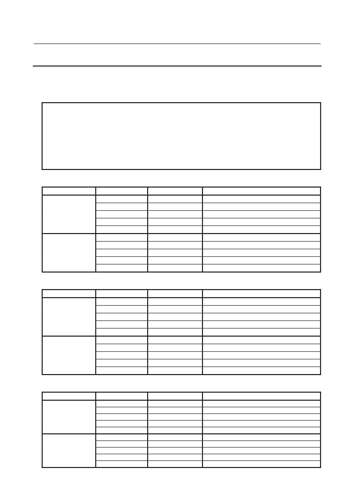
A.3 STANDARD PARAMETER SETTING TABLES
This section defines the standard minimum data units and valid data ranges of the CNC parameters of the
real type, real machine group type, real path type, real axis type, and real spindle type. The data type and
unit of data of each parameter conform to the specifications of each function.
NOTE
1 Values are rounded up or down to the nearest multiples of the minimum data
unit.
2 A valid data range means data input limits, and may differ from values
representing actual performance.
3 For information on the ranges of commands to the CNC, refer to Appendix D,
"Range of Command Value" in the OPERATOR’S MANUAL (Common to Lathe
System / Machining Center System.
(A) Length and angle parameters (type 1)
Unit of data
Increment system
Minimum data unit
Valid data range
IS-A
0.01
-999999.99
to
+999999.99
IS-B
0.001
-999999.999
to
+999999.999
mm
IS-C
0.0001
-99999.9999
to
+99999.9999
deg.
IS-D
0.00001
-9999.99999
to
+9999.99999
IS-E
0.000001
-999.999999 to
+999.999999
IS-A
0.001
-99999.999
to
+99999.999
IS-B
0.0001
-99999.9999
to
+99999.9999
inch
IS-C
0.00001
-9999.99999
to
+9999.99999
IS-D
0.000001
-999.999999 to
+999.999999
IS-E
0.0000001
-99.9999999 to
+99.9999999
(B) Length and angle parameters (type 2)
Unit of data
Increment system
Minimum data unit
Valid data range
IS-A
0.01
0.00
to
+999999.99
IS-B
0.001
0.000
to
+999999.999
mm
IS-C
0.0001
0.0000
to
+99999.9999
deg.
IS-D
0.00001
0.00000
to
+9999.99999
IS-E
0.000001
0.000000
to
+999.999999
IS-A
0.001
0.000
to
+99999.999
IS-B
0.0001
0.0000
to
+99999.9999
inch
IS-C
0.00001
0.00000
to
+9999.99999
IS-D
0.000001
0.000000
to
+999.999999
IS-E
0.0000001
0.0000000 to
+99.9999999
(C) Velocity and angular velocity parameters
Unit of data
Increment system
Minimum data unit
Valid data range
IS-A
0.01
0.00
to +999000.00
IS-B
0.001
0.000
to +999000.000
mm/min
IS-C
0.0001
0.0000
to
+99999.9999
degree/min
IS-D
0.00001
0.00000
to
+9999.99999
IS-E
0.000001
0.000000
to
+999.999999
IS-A
0.001
0.000
to
+96000.000
IS-B
0.0001
0.0000
to
+9600.0000
inch/min
IS-C
0.00001
0.00000
to
+4000.00000
IS-D
0.000001
0.000000
to
+400.000000
IS-E
0.0000001
0.0000000 to
+40.0000000
- 433 -
A.PARAMETERS
APPENDIX
B-64484EN-2/02
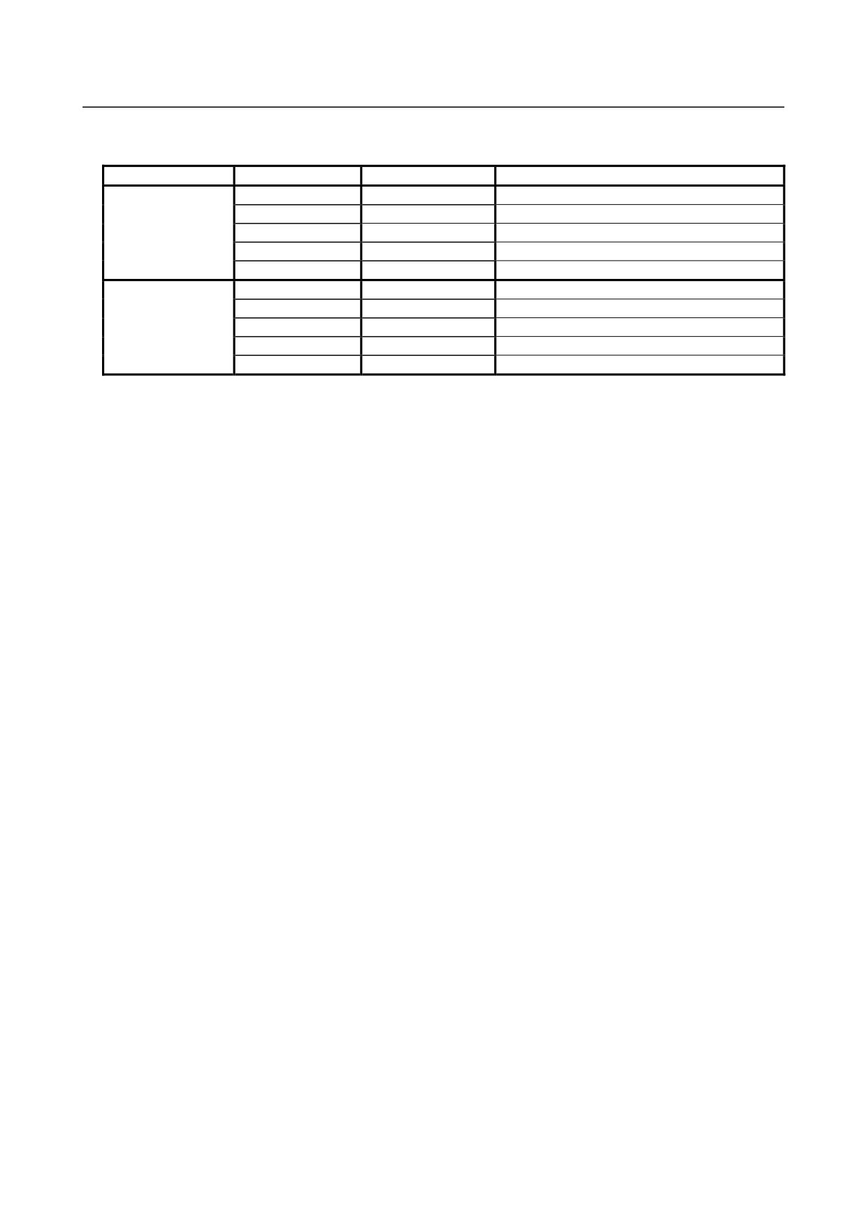
(D) Acceleration and angular acceleration parameters
Unit of data
Increment system
Minimum data unit
Valid data range
IS-A
0.01
0.00
to
+999999.99
IS-B
0.001
0.000
to
+999999.999
mm/sec2
IS-C
0.0001
0.0000
to
+99999.9999
deg./sec2
IS-D
0.00001
0.00000
to
+9999.99999
IS-E
0.000001
0.000000
to
+999.999999
IS-A
0.001
0.000
to
+99999.999
IS-B
0.0001
0.0000
to
+99999.9999
inch/sec2
IS-C
0.00001
0.00000
to
+9999.99999
IS-D
0.000001
0.000000
to
+999.999999
IS-E
0.0000001
0.0000000
to
+99.9999999
- 434 -