FANUC Series 0i-MODEL D, Series 0i Mate-MODEL D. CONNECTION MANUAL (HARDWARE) - page 10
B-64303EN/03
9.CONNECTION OF I/O Link SLAVE DEVICES
9.9.7.2 Detachable key top
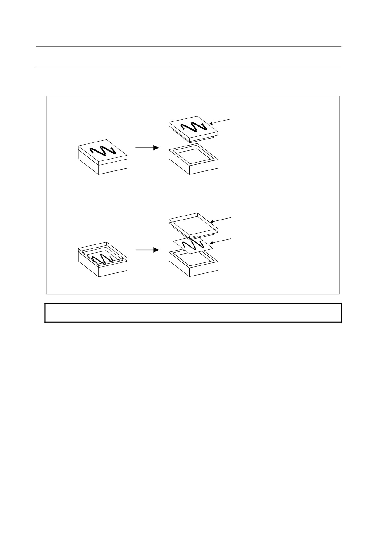
Keyboard of machine operator's panel has 55 keys. All key tops are detachable. MTB can customize keys
and make his original key layout easily. And using transparent key top (optional), a film sheet with
marking is inserted into the key.
Symbolic key top or
Blank key top
Transparent key top
Film sheet (*)
(12.5mm×12.5mm, t=0.1mm Max.)
NOTE
(*) Use the oil-proof sheet in the environment which oil is used for.
- 257 -
9.CONNECTION OF I/O Link SLAVE DEVICES
B-64303EN/03
9.10 CONNECTION TO THE SMALL MACHINE OPERATOR'S
PANEL OR SMALL MACHINE OPERATOR'S PANEL B
9.10.1 Overview
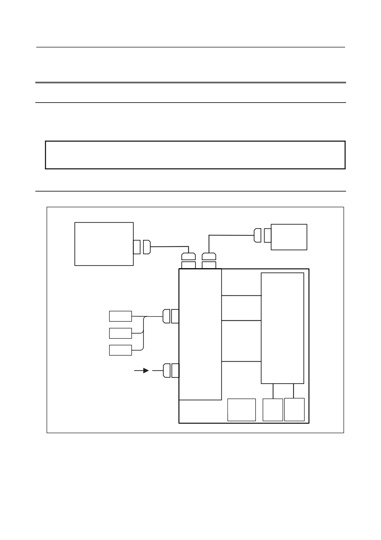
The small machine operator's panel or small machine operator's panel B is a machine operator's panel
connected to the CNC with an I/O Link. The operator's panel contains 30 keys, an emergency stop
switch, and two override rotary switches.
NOTE
Use a 3-keystroke support model, which does not accept more than three
simultaneous keystrokes. See Subsection 9.10.10.2, "Order specification".
9.10.2 Overall Connection Diagram
For small machine operator's panel
CNC
I/O Unit
I/O ÕƯÄ
Control unit or slave unit
I/O Link
JD1B
in the previous‚Ìstage
ƒXƒŒ [ƒuƒ†ƒjƒbƒg
I/O Link
JD1A (JD51A)
Small machine
operator's panel
JD1B JD1A
Operator's
‘€ ì”ÕI/O
Keyboa
rdƒh
panel I/O
CE53
CE53
MPG
JA3
CE54
CE54
MPG
MPG
CPD1(OUT)
CPD(IN)
+24V +24 V“dŒ¹ply
CPD1(IN)
CM65 CM66
Emergency
Rotar°
y
Rotar°
y
stop switch
switch
switch
½²¯Á
(SB1)
(SA1)
(SA2)
- 258 -
B-64303EN/03
9.CONNECTION OF I/O Link SLAVE DEVICES
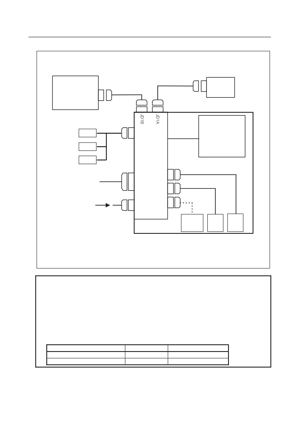
For small machine operator's panel B
CNC or I/O
Link
slave unit in
the
I/O Link slave unit in
Œã’i‚ÌI/O Link
previous stagejƒbƒg
the next stageƒjƒbƒg
JD1B
I/O Link
JD1A (JD51A)
¬Œ^‹@ŠB‘€ ì”Õ
Small machine operator's panel
Keybo
ardh
MPG
JA3
CE72
CE72
MPG
I/O board
MPG
CM66
General-purpose DI/DO
DI: 24 pointsDI:24“_
CE73
DO: 16 pointDO:16“_
CM65
+24VDC
CE74
CA102
power supply
Emergency
Rotary
Rotary
stop switch
switch
switch
½²¯Á
(SB1)
(SA1)
(SA2)
The small machine operator's panel B is different from the small machine operator's panel in connection as
¬Œ^‹@ŠB‘€ ì”ÕB‚Í
¬Œ^‹@ŠB‘€ ì”Õ‚Æ”äŠr‚µ‚Ä A‰º‹L‚Ì Ú‘±‚ªˆÙ‚È‚è‚Ü‚· B
describe
d below.
E
”ñ í’âŽ~ƒXƒCƒbƒ` (SB1) ‚ðƒRƒlƒNƒ^CE74‚É Ú‘±‚·‚邱‚Æ‚ª‚Å‚«‚Ü‚· BCE74‚ÍI/Oƒ{
[ƒh“à‚ŔėpDI‚Ì
- The emergency stop switch (SB1) can be connected to connector CE74. Connector CE74 is connected to
general-purpose DI address Xm2+4.4 in the I/O board.‚Ü‚· B
- The following general-purpose DI/DO points can be connected: 24 DI points and 16 DO points.
NOTE
1 If this operator's panel is used together with a unit (such as an I/O module for
branching) connected to an I/O Link having another MPG interface, only the
MPG interface of the unit (module) nearest the CNC connected to the I/O Link
will be enabled by default. To enable the MPG interfaces of the second and
subsequent units, set appropriate parameters. For details, refer to the manual
supplied with the NC used.
2 The following screw-on connectors cannot be used for the connection of an I/O
Link and manual pulse generator.
Connectors that cannot used on the cable side
Specification
Manufacturer
Connector case
FI-20-CV7
Hirose Electric Co., Ltd.
Connector case and connector
FI30-20S-CV7
Hirose Electric Co., Ltd.
- 259 -
9.CONNECTION OF I/O Link SLAVE DEVICES
B-64303EN/03
9.10.3 Connection of Each Section
9.10.3.1 Power connection
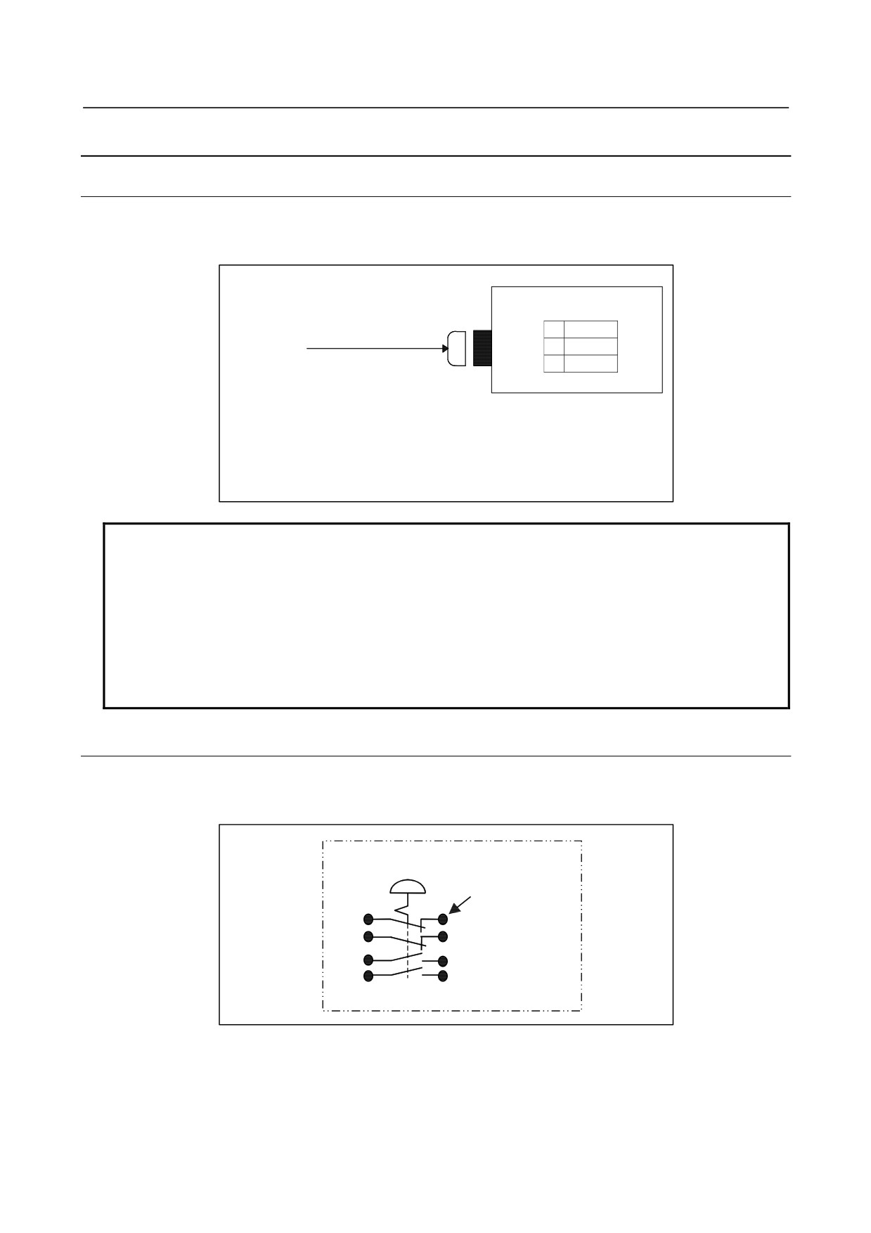
To the CPD1 connector, shown in the figure below, supply the power necessary for this operator's panel
to operate, as well as the power for the general-purpose DI.
CPD1
01
+24V
02
V
0V
24VDC“dŒ¹
02
0V
power supply
03
03
Recommended con
„nector for use on the CPD1 cable side
A02B-0120-K324 (including the following connector housing and contact)
ƒnƒEƒWƒ“ƒO3ƒsƒ“ j
Housing: Japan AMP 1-178288-3 (3 pins)
ƒRƒ“ƒ^ƒNƒg
Contact: Japan AMP 1-175218-5
NOTE
The +24V power supplied to this connector must be turned OFF during
operation. Turning it OFF will cause a CNC communication alarm to be
generated. Make sure that at power ON, the supply of this +24V power is at the
same time as or earlier than the supply of the power to the CNC and that at
power OFF, it is at the same time as or later than the interruption of the power to
the CNC.
When the CNC connected to this operator's panel with an I/O Link is to be turned
off, the power to this operator's panel must also be turned off.
9.10.3.2 Emergency stop switch
The emergency stop switch has contact A in two circuits and contact B in two circuits.
(This signal is
not sent to the CNC with a FANUC I/O Link.)
The machine tool builder is required to connect the switch to other DI/DO devices.
Emergency stop switch (SB1)
M3.5 screw terminal
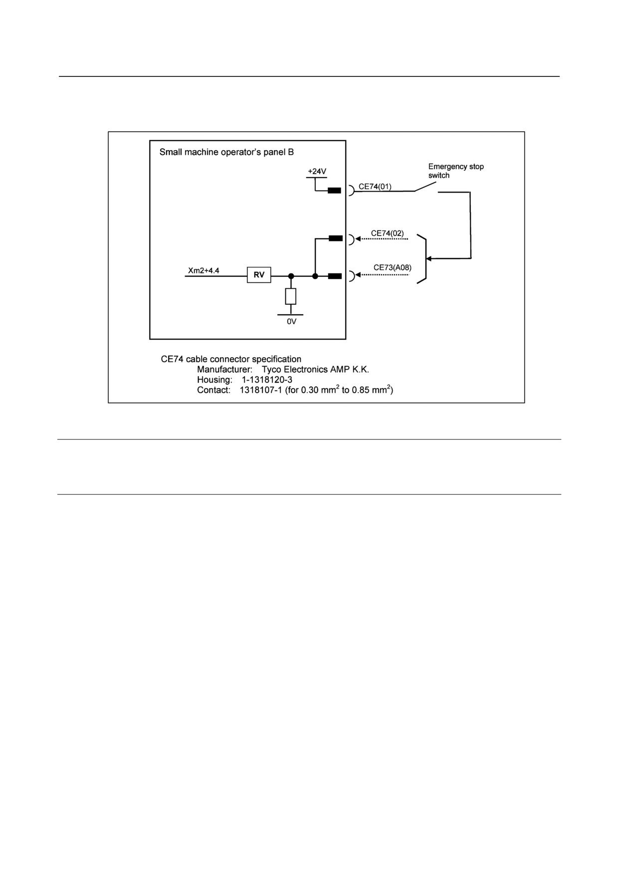
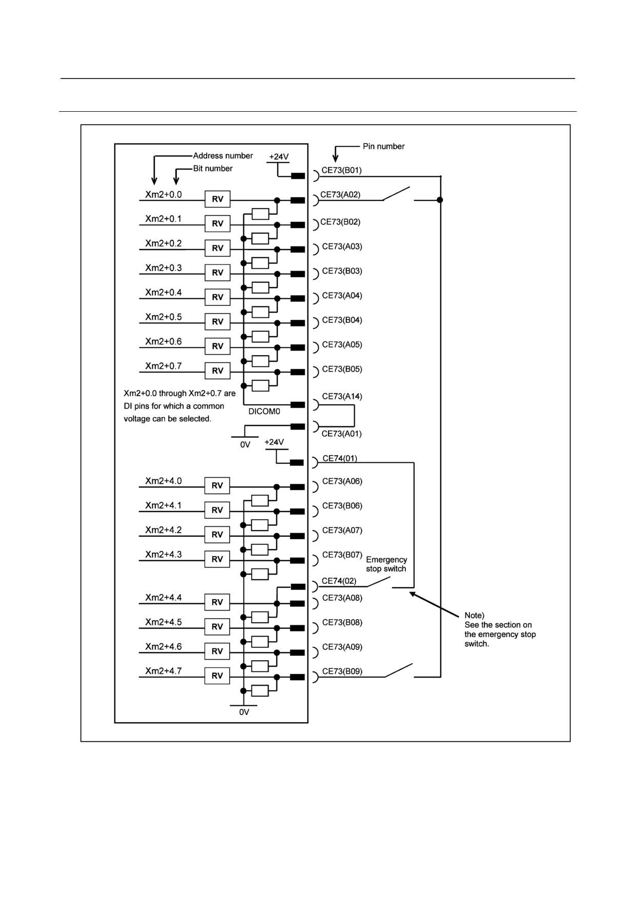
With the small machine operator's panel B, the input (pin 02) of the emergency stop input connector
(CE74) is connected to general-purpose DI address Xm2+4.4 in the I/O board as shown below.
When the general-purpose DI start address is X0004, the input of CE74 is X0008.4, to which the signal of
the emergency stop switch can be directly connected.
- 260 -
B-64303EN/03
9.CONNECTION OF I/O Link SLAVE DEVICES
When the input signal (Xm2+4.4) is used as an emergency stop signal, the signal should be input to pin
02 of the emergency stop input connector (CE74) or pin A08 of the general-purpose DI/DO connector
(CE73).
9.10.3.3 I/O Link connection
See Section 8.2.
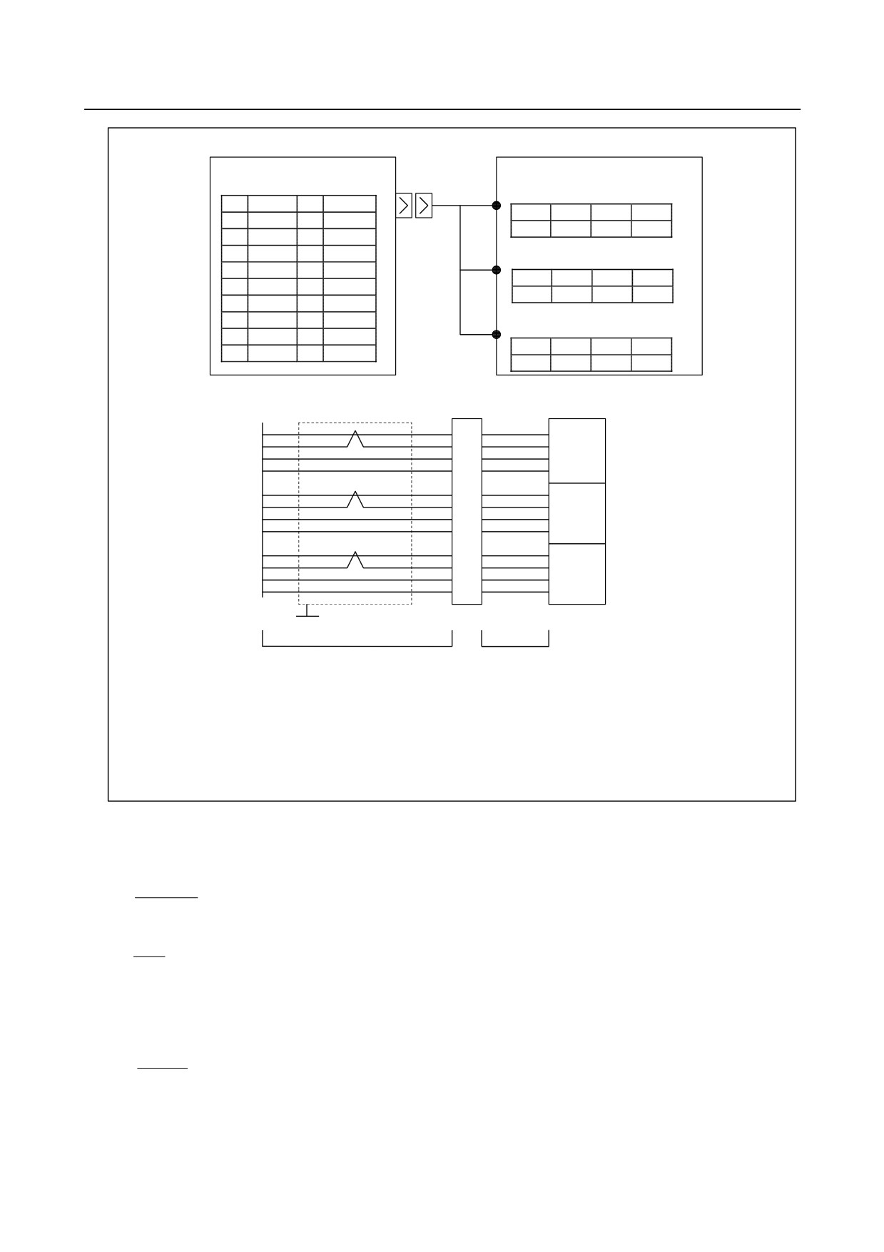
9.10.3.4 Manual pulse generator connection
An example in which three manual pulse generators are connected is given below. If this operator's
panel is used together with a unit (such as an I/O module for connection) connected to an I/O Link having
another MPG interface, only the MPG interface of the unit (module) nearest the CNC connected to the
I/O Link will be enabled by default. To enable the MPG interfaces of the second and subsequent units,
set appropriate parameters. For details, refer to the manual supplied with the CNC used.
- 261 -
9.CONNECTION OF I/O Link SLAVE DEVICES
B-64303EN/03
Small machine operator's panel
JA3
Manual pulse generator #1
(M3 screw terminal)
1
HA1
11
3
4
5
6
2
HB1
12
0V
+5V
0V
HA1
HB1
3
HA2
13
Manual pulse generator #2
4
HB2
14
0V
(M3 screw terminal)
5
HA3
15
3
4
5
6
6
HB3
16
0V
+5V
0V
HA2
HB2
7
17
Manual pulse generator #3
8
18
+5V
(M3 screw terminal)
9
+5V
19
3
4
5
6
10
20
+5V
+5V
0V
HA3
HB3
Cable connection
Terminal block
Manual pulse generators
1
#1
HA1
7BK
HA1
5
HA1
HB1
2
7WH
6
HB1
HB1
+5V
9
5RD
3
+5V
+5V
0V
12
5BK
4
0V
0V
HA2
3
8RD
5
HA2
#2
HA2
HB2
4
8BK
6
HB2
HB2
+5V
18
4RD
3
+5V
+5V
0V
14
3BK
4
0V
0V
HA3
5
5
9BK
#3
HA3
HA3
HB3
6
9WH
6
HB3
HB3
+5V
20
6RD
3
+5V
+5V
0V
16
1BK
4
0V
0V
GROUNDING PLATE
Wiring
Cable
Recommended wire material: A66L-0001-0286 (#20 AWG y 6 + #24 AWG y 3 pair)
Recommended connectors: A02B-0120-K303 (including the following connector and case)
(Connector: Hirose Electric FI40B-2015S Soldering type)
(Case: Hirose Electric FI-20-CV)
Recommended cable: A02B-0120-K841 (7 m) (cable for three manual pulse generators)
A02B-0120-K848 (7 m) (cable for two manual pulse generators)
A02B-0120-K847 (7 m) (cable for one manual pulse generator)
(These cables are not used for the connection in the portion indicated by "Wiring".)
Calculate the maximum allowable length of the cable for the manual pulse generator, with the method
described below.
Manual pulse generators are supplied with 5 VDC power. The drop in voltage due to cable resistance
must not exceed 0.2V (on 0V and 5V lines in total).
0.1×R×2L
0.2≧
m
Where
m
0.1
:
Power supply current for the manual pulse generator = 0.1 A
L≦
R
R
:
Wire resistance per unit length [Ω/m]
m
:
Number of 0-V wires (= number of 5-V wires)
L
:
Cable length [m]
Therefore,
3
L≦
=76.75 [m]
0.0394
Example: When cable A66L-0001-0286 is used
This cable consists of three pairs of signal lines and six power wires (20/0.18, 0.0394 Ω/m).
When these three cables are used for 0V and 5V lines, the cable length is:
- 262 -
B-64303EN/03
9.CONNECTION OF I/O Link SLAVE DEVICES
Thus, the length is 76.75 m.
(Because of the applicable regulation of FANUC, however, the length is
limited to 50 m.)
For two units, the cable can be extended to 38.37 m.
For three units, it can be extended to 25.58 m.
If the cable A66L-0001-0284#10P is used,
the cable can be extended to 12.88 m for one unit,
6.44 m for two units, and
4.29 m for three units.
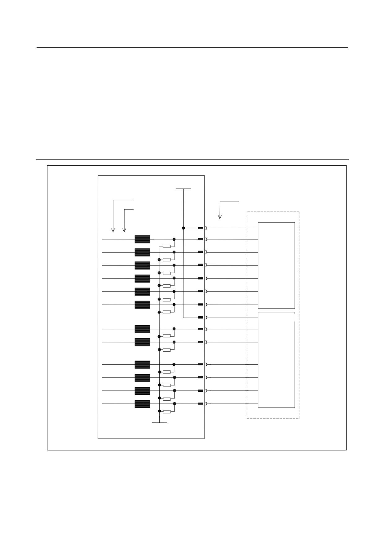
9.10.4 DI Signal Connection (Rotary Switch Connection)
+24V
Address No.
ƒAƒhƒŒƒX”Ô †
Terminal No.
†
Bit No.”Ô
†
CM65(A04)
D
Rotary switch
CM65(B05)
(SA1)
Xm+0.0
A
RV
Xm+0.1
CM65(A03)
F
RV
Xm+0.2
CM65(A05)
B
RV
Xm+0.3
CM65(B03)
E
RV
Xm+0.4
CM65(B04)
C
RV
Xm+0.5
CM65(B02)
G
RV
CM66(A04)
D
Rotary switch
(SA2)
Xm+1.0
CM66(B05)
A
RV
Xm+1.1
CM66(A03)
F
RV
Xm+1.2
CM66(A05)
B
RV
Xm+1.3
CM66(B03)
E
RV
Xm+1.4
CM66(B04
C
RV
Xm+1.5
CM66(B02)
G
RV
0V
- 263 -
9.CONNECTION OF I/O Link SLAVE DEVICES
B-64303EN/03
9.10.5
General-purpose DI/DO Connection (Only for the Small
Machine Operator's Panel B)
9.10.5.1
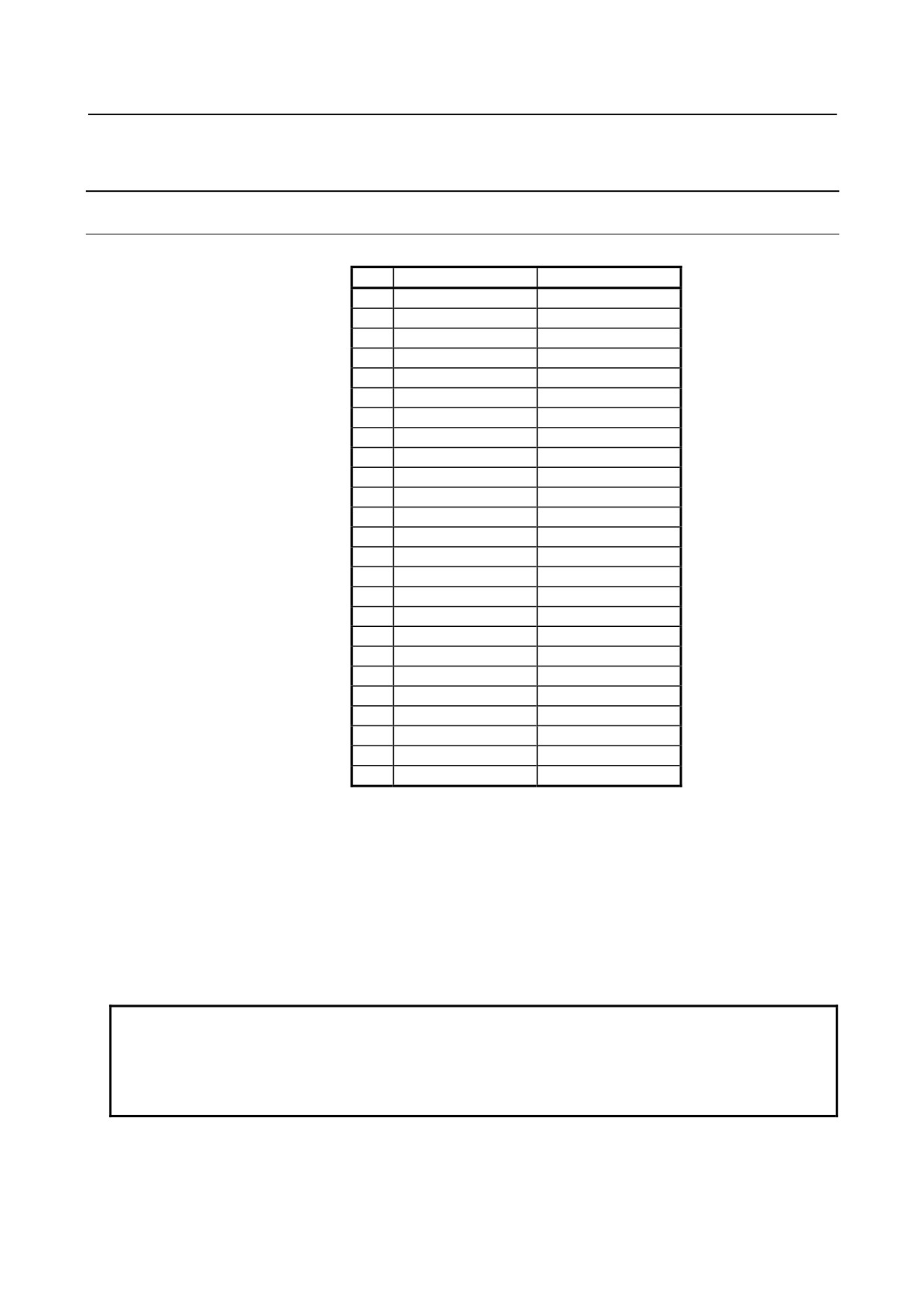
Connector pin allocation
General-purpose DI/DO (CE73)
A
B
01
0V
+24V
02
Xm2+0.0
Xm2+0.1
03
Xm2+0.2
Xm2+0.3
04
Xm2+0.4
Xm2+0.5
05
Xm2+0.6
Xm2+0.7
06
Xm2+4.0
Xm2+4.1
07
Xm2+4.2
Xm2+4.3
08
Xm2+4.4
Xm2+4.5
09
Xm2+4.6
Xm2+4.7
10
Xm2+5.0
Xm2+5.1
11
Xm2+5.2
Xm2+5.3
12
Xm2+5.4
Xm2+5.5
13
Xm2+5.6
Xm2+5.7
14
DICOM0
DICOM5
15
16
Yn2+0.0
Yn2+0.1
17
Yn2+0.2
Yn2+0.3
18
Yn2+0.4
Yn2+0.5
19
Yn2+0.6
Yn2+0.7
20
Yn2+1.0
Yn2+1.1
21
Yn2+1.2
Yn2+1.3
22
Yn2+1.4
Yn2+1.5
23
Yn2+1.6
Yn2+1.7
24
DOCOM
DOCOM
25
DOCOM
DOCOM
Flat cable connector specification:
A02B-0120-K342
(Hirose Electric Co., Ltd. HIF3BB-50D-2.54R)
50 contacts
Cable wire specification:
A02B-0120-K886
(50-pin cable (Hitachi Cable, Ltd. or Oki Electric Cable Co., Ltd.))
Maximum cable length:
50m
NOTE
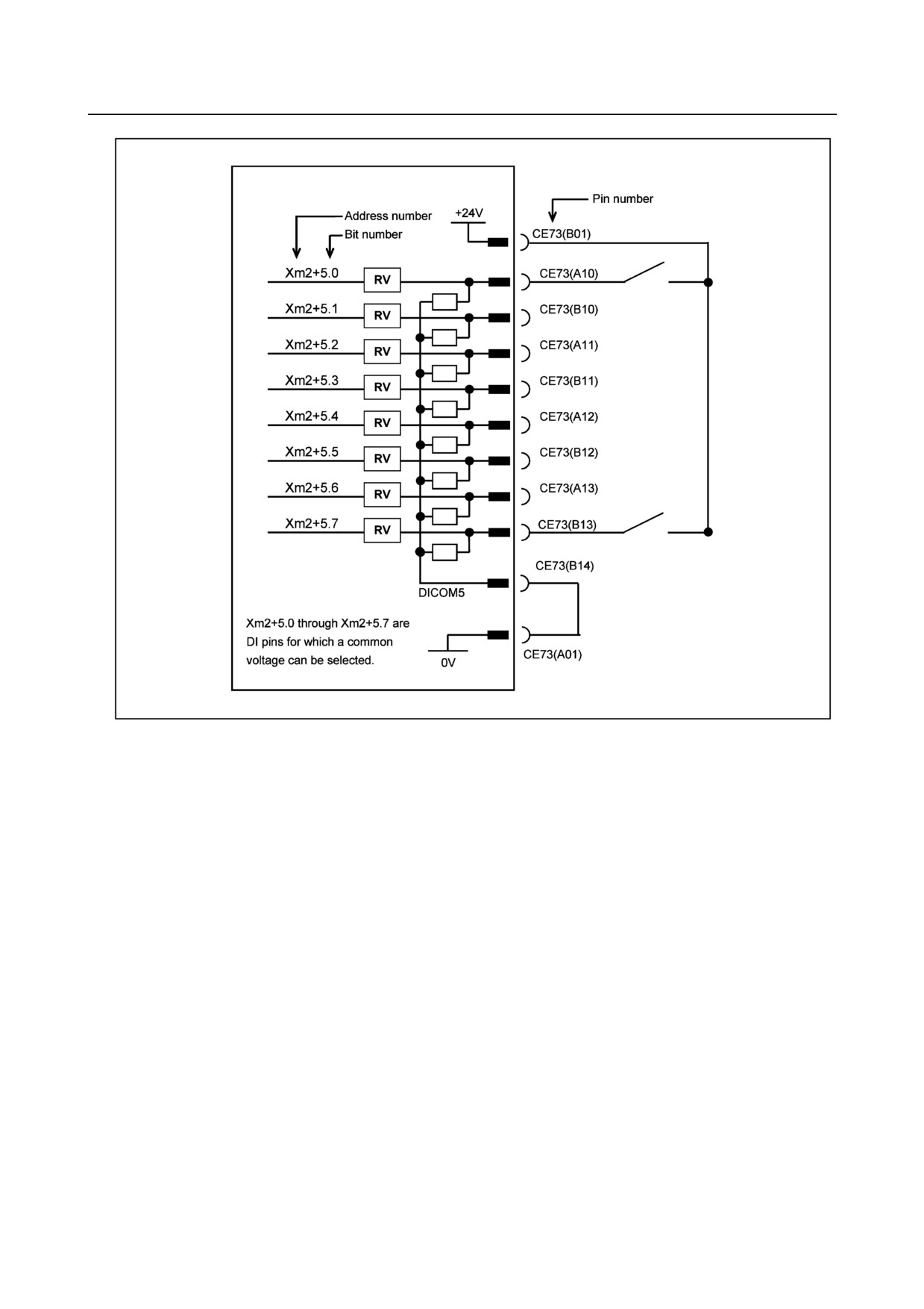
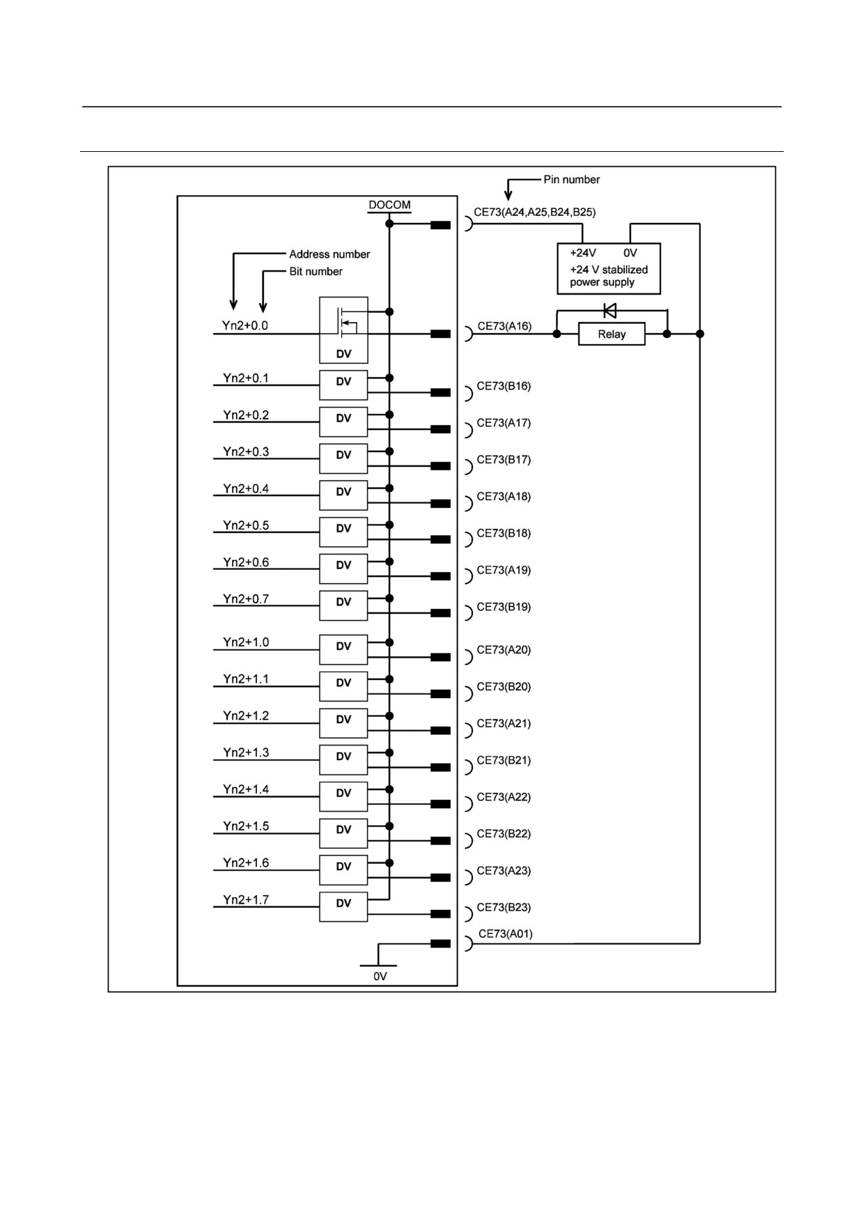
1 Xm2 and Yn2 indicate the general-purpose DI/DO start addresses in the I/O
Link.
2 The B01 pin, +24 V, is 24 VDC output for DI signals. Do not supply 24 VDC to
this pin from the outside.
- 264 -
B-64303EN/03
9.CONNECTION OF I/O Link SLAVE DEVICES
9.10.5.2 General-purpose DI (input signal) connection
- 265 -
9.CONNECTION OF I/O Link SLAVE DEVICES
B-64303EN/03
- 266 -
B-64303EN/03
9.CONNECTION OF I/O Link SLAVE DEVICES
9.10.5.3 General-purpose DO (output signal) connection
- 267 -
9.CONNECTION OF I/O Link SLAVE DEVICES
B-64303EN/03
DO signal reaction to a system alarm
There is a possibility that the Operator’s panel will not operate normally due to a failure of CNC or I/O
Link slave module, or abnormally power supply voltage. To prevent accidents even in this case, design
the machine to operate safely by making a safety circuit outside the Operator’s panel.
The circuit of this Operator’s panel is designed so that all DO signals are turned off if a system alarm is
occurred in the CNC which controls the Operator’s panel, or if a power of the CNC or the Operator’s
panel is turned off. However, it cannot be guaranteed that DO signals of the Operator’s panel will
certainly be turned off. Therefore, manage signals related to safety by making a safety circuit outside this
Operator’s panel.
9.10.6 I/O Address
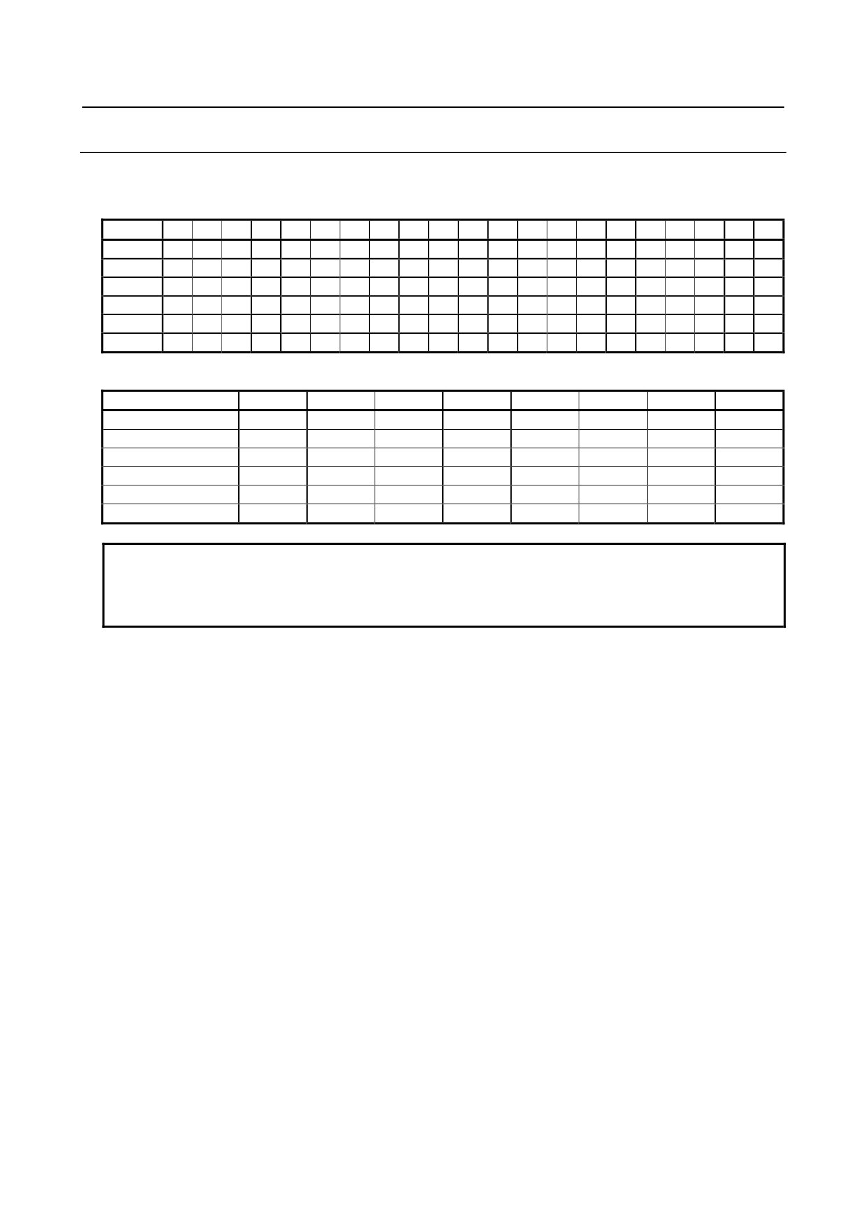
9.10.6.1 Keyboard of the operator's panel
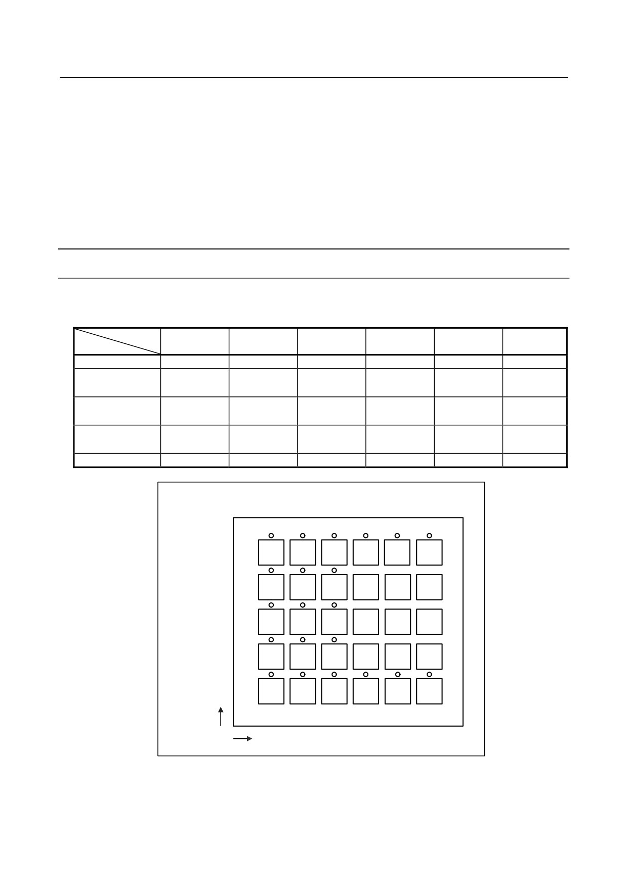
The I/O address correspondence between the key switches on the machine operator's panel and LEDs are
as follows.
BIT
5
4
3
2
1
0
Key/LED
Xm+4/Yn+0
A6
A5
A4
A3
A2
A1
Xm+5/Yn+1
B6/
B5/
B4/
B3
B2
B1
Without LED
Without LED
Without LED
Xm+6/Yn+2
C6/
C5/
C4/
C3
C2
C1
Without LED
Without LED
Without LED
Xm+7/Yn+3
D6/
D5/
D4/
D3
D2
D1
Without LED
Without LED
Without LED
Xm+8/Yn+4
E6
E5
E4
E3
E2
E1
Key switch/LED arrangement
A
B
C
D
E
ƒAAddress
1
2
3
4
5
6
- 268 -
B-64303EN/03
9.CONNECTION OF I/O Link SLAVE DEVICES
9.10.6.2 Override signals
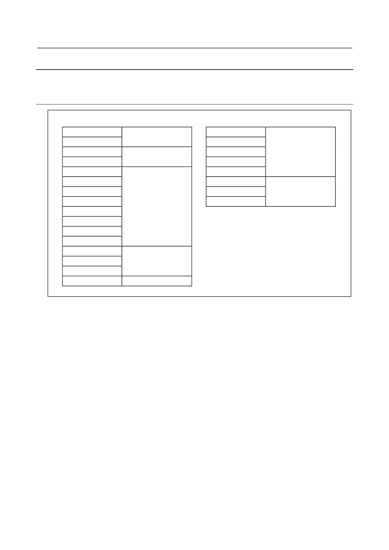
Gray codes are output according to the table below.
Rotary switch (SA1)
%
0
1
2
4
6
8
10
15
20
30
40
50
60
70
80
90
95
100
105
110
120
Xm+0.0
0
1
1
0
0
1
1
0
0
1
1
0
0
1
1
0
0
1
1
0
0
Xm+0.1
0
0
1
1
1
1
0
0
0
0
1
1
1
1
0
0
0
0
1
1
1
Xm+0.2
0
0
0
0
1
1
1
1
1
1
1
1
0
0
0
0
0
0
0
0
1
Xm+0.3
0
0
0
0
0
0
0
0
1
1
1
1
1
1
1
1
1
1
1
1
1
Xm+0.4
0
0
0
0
0
0
0
0
0
0
0
0
0
0
0
0
1
1
1
1
1
Xm+0.5
0
1
0
1
0
1
0
1
0
1
0
1
0
1
0
1
0
1
0
1
0
Rotary switch (SA2)
%
50
60
70
80
90
100
110
120
Xm+1.0
0
1
1
0
0
1
1
0
Xm+1.1
0
0
1
1
1
1
0
0
Xm+1.2
0
0
0
0
1
1
1
1
Xm+1.3
0
0
0
0
0
0
0
0
Xm+1.4
0
1
0
1
0
1
0
1
Xm+1.5
0
0
0
0
0
0
0
0
NOTE
1 Xm+0.5 and Xm+1.4 are parity bits.
2 If parity bits are used, the output timing of override signals may differ from that of
the parity bits.
- 269 -
9.CONNECTION OF I/O Link SLAVE DEVICES
B-64303EN/03
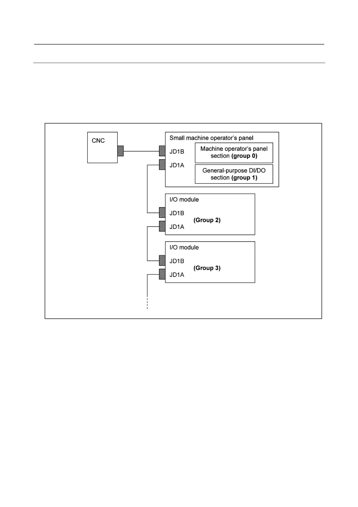
9.10.7 I/O Address Allocation
The I/O address maps for the main panel are as follows.
9.10.7.1 For small machine operator's panel
Map of the DI space
Map for the DO space
Xm+0
General-purpose DI
Yn+0
Xm+1
(Rotary switch)
Yn+1
Operator's panel Keyboard
Xm+2
Yn+2
Reserved
(LED)
Xm+3
Yn+3
Xm+4
Yn+4
Xm+5
Yn+5
Xm+6
Yn+6
Reserved
Xm+7
Operator's panel Keyboard
Yn+7
Xm+8
(Key switch)
Xm+9
Xm+10
Xm+11
Xm+12 (1st MPG)
Xm+13 (2nd MPG)
MPG
Xm+14 (3rd MPG)
Xm+15
Reserved
- 270 -
B-64303EN/03
9.CONNECTION OF I/O Link SLAVE DEVICES
9.10.7.2 For small machine operator's panel B
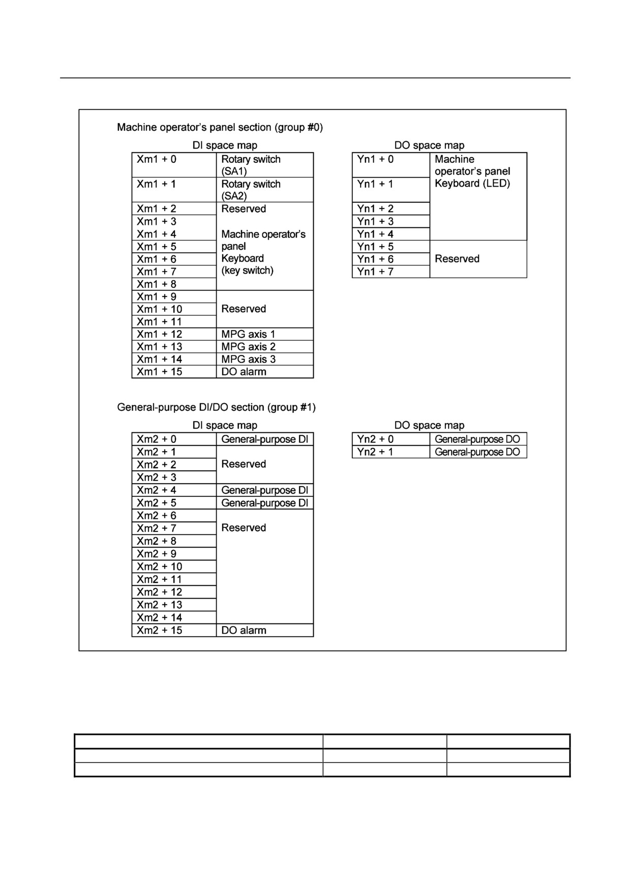
For I/O Link allocation, each unit is usually allocated as one group. However, as shown below, one unit
of the small machine operator's panel B has two functions, the machine operator's panel section and the
general-purpose DI/DO section, which are allocated as sequential groups in that order.
The following is an example in which the machine operator's panel section is allocated as group 0.
In this case, the general-purpose DI/DO section is allocated as group 1.
The I/O module in the next stage is allocated as group 2.
JD51A
- 271 -
9.CONNECTION OF I/O Link SLAVE DEVICES
B-64303EN/03
I/O address maps of the small machine operator's panel B
Xm1 and Yn1 indicate the start addresses for the machine operator's panel section of the small machine
operator's panel B in the I/O Link, while Xm2 and Yn2 indicate the start addresses for the
general-purpose DI/DO section.
Module name
DI
DO
Machine operator's panel section
CM16I (16byte)
CM08O (8byte)
General-purpose DI/DO section
CM06I (6byte)
CM02O (2byte)
To use a DO alarm in the general-purpose DI/DO space, 16-byte allocation is required. In this case, set
CM16I as a DI module name in the general-purpose DI/DO section.
- 272 -
B-64303EN/03
9.CONNECTION OF I/O Link SLAVE DEVICES
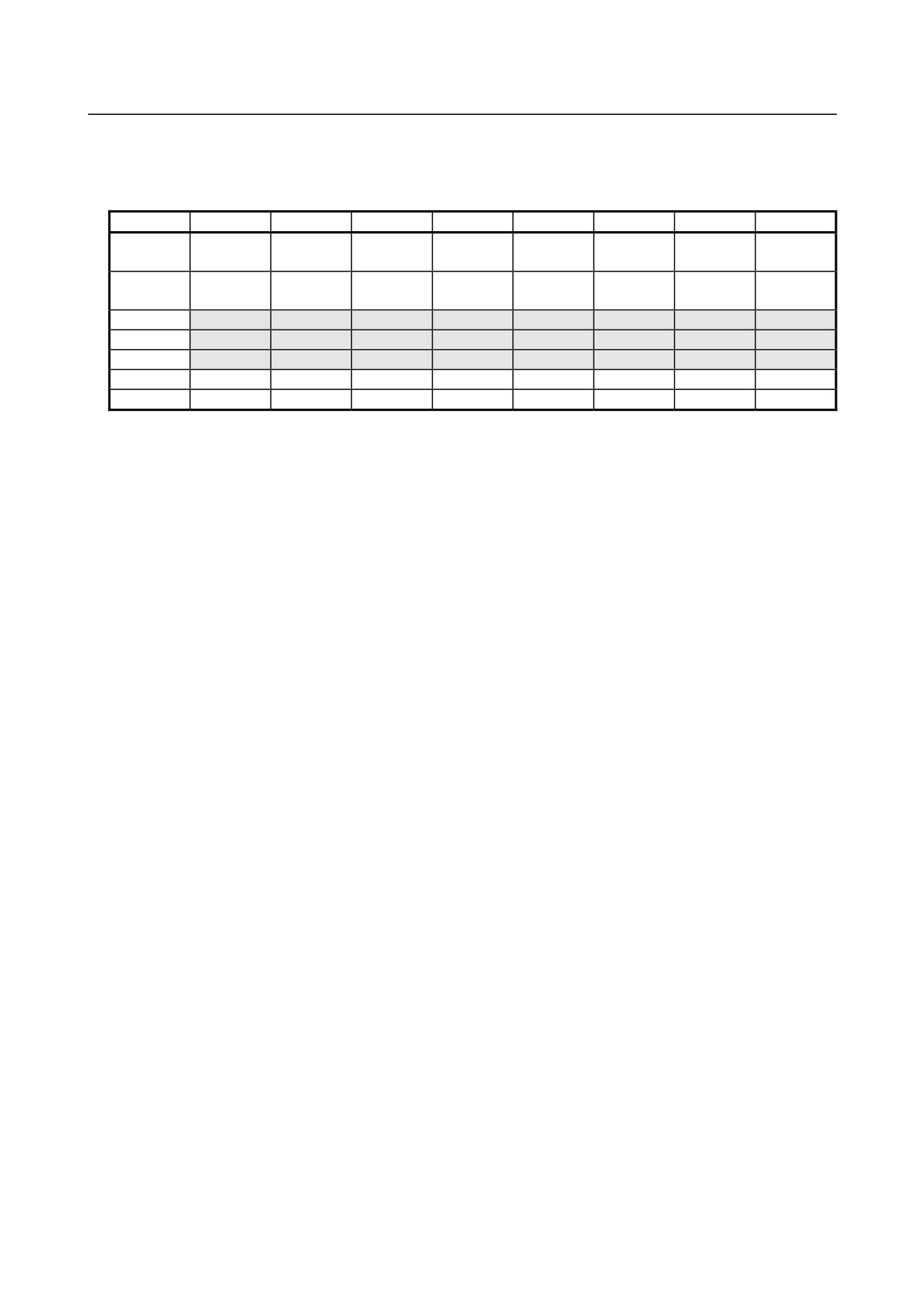
When DI addresses in the general-purpose DI/DO section are allocated starting at X0004, the fixed
signals such as SKIP, *DECn, and *ESP can be allocated as shown below.
Fixed addresses directly supervised by the CNC
7
6
5
4
3
2
1
0
X004
SKIP
ESKIP
-MIT2
+MIT2
-MIT1
+MIT1
ZAE
XAE
SKIP6
SKIP5
SKIP4
SKIP3
SKIP2
SKIP8
SKIP7
SKIP
ESKIP
SKIP5
SKIP4
SKIP3
ZAE
YAE
XAE
SKIP6
SKIP2
SKIP8
SKIP7
X005
X006
X007
X008
*ESP
X009
*DEC4
*DEC3
*DEC2
*DEC1
- 273 -
9.CONNECTION OF I/O Link SLAVE DEVICES
B-64303EN/03
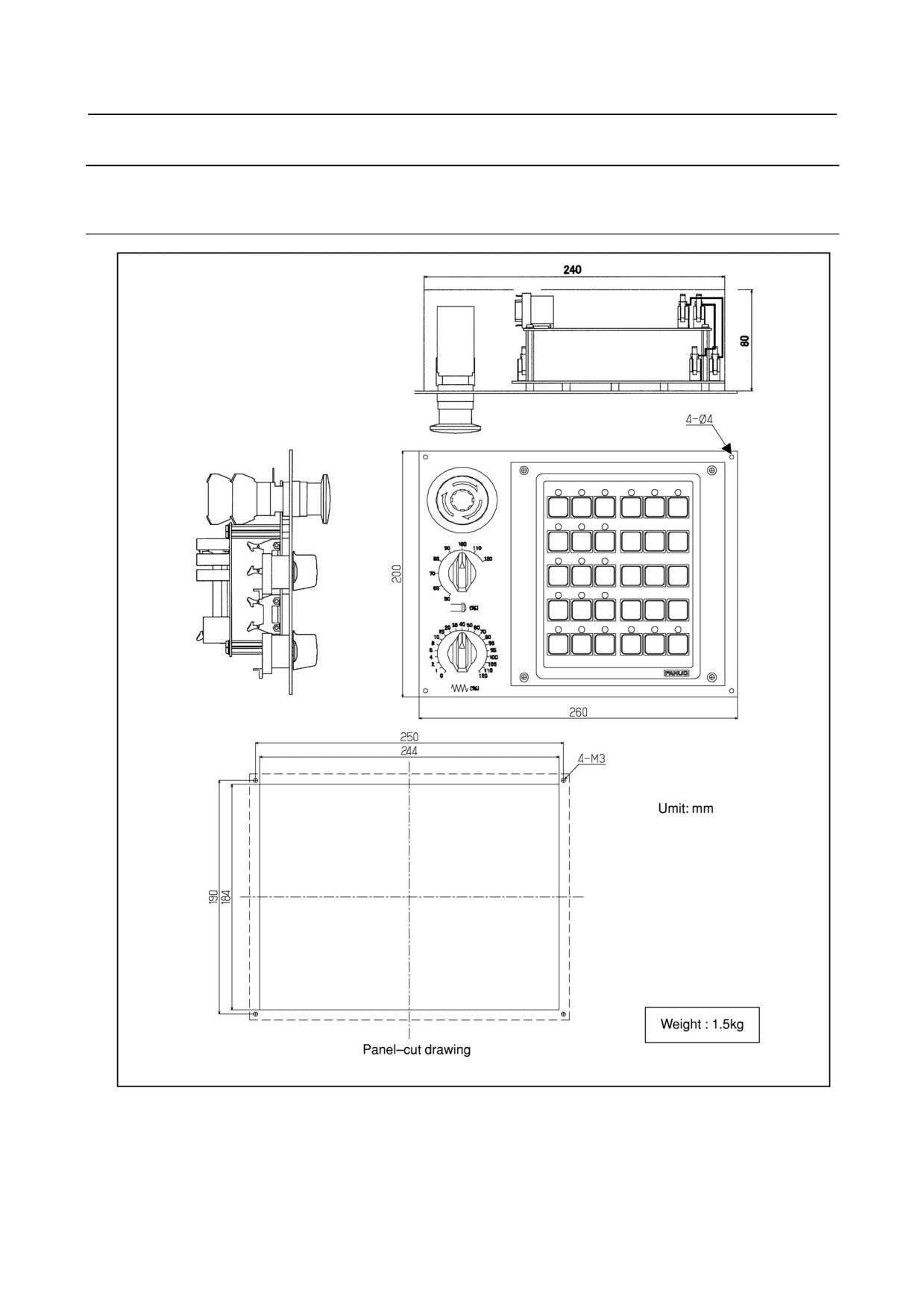
9.10.8 External Dimensions
9.10.8.1 Outline drawing and panel-cut drawing of the small machine
operator's panel
- 274 -
B-64303EN/03
9.CONNECTION OF I/O Link SLAVE DEVICES
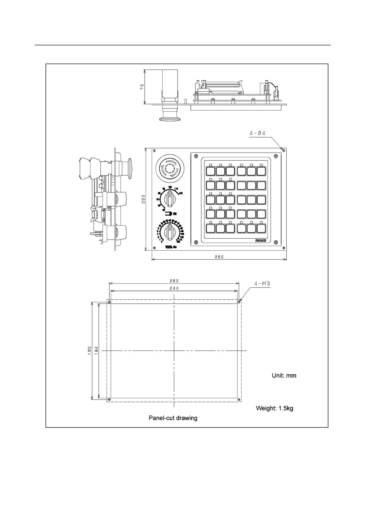
Small machine operator's panel B
- 275 -
9.CONNECTION OF I/O Link SLAVE DEVICES
B-64303EN/03
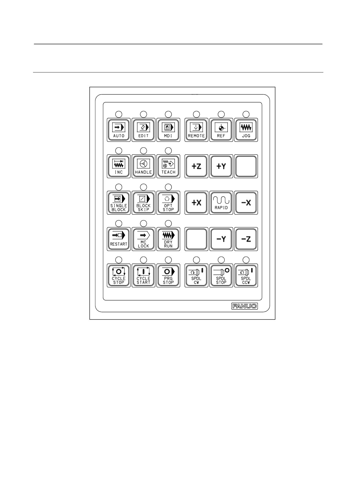
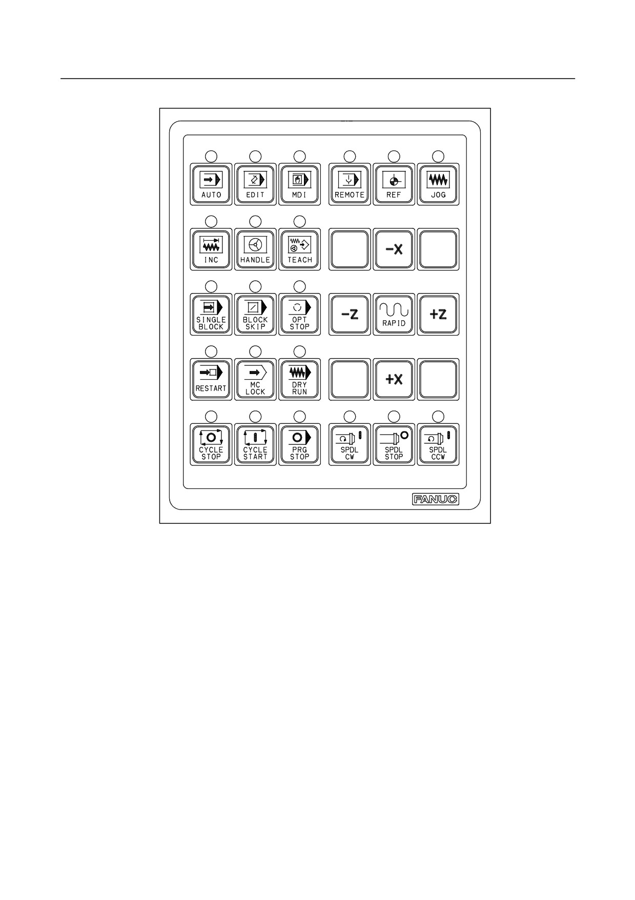
9.10.8.2 Layout of the key sheet (Same for both the small machine
operator's panel and small machine operator's panel B)
M series
- 276 -
B-64303EN/03
9.CONNECTION OF I/O Link SLAVE DEVICES
T series
- 277 -
9.CONNECTION OF I/O Link SLAVE DEVICES
B-64303EN/03
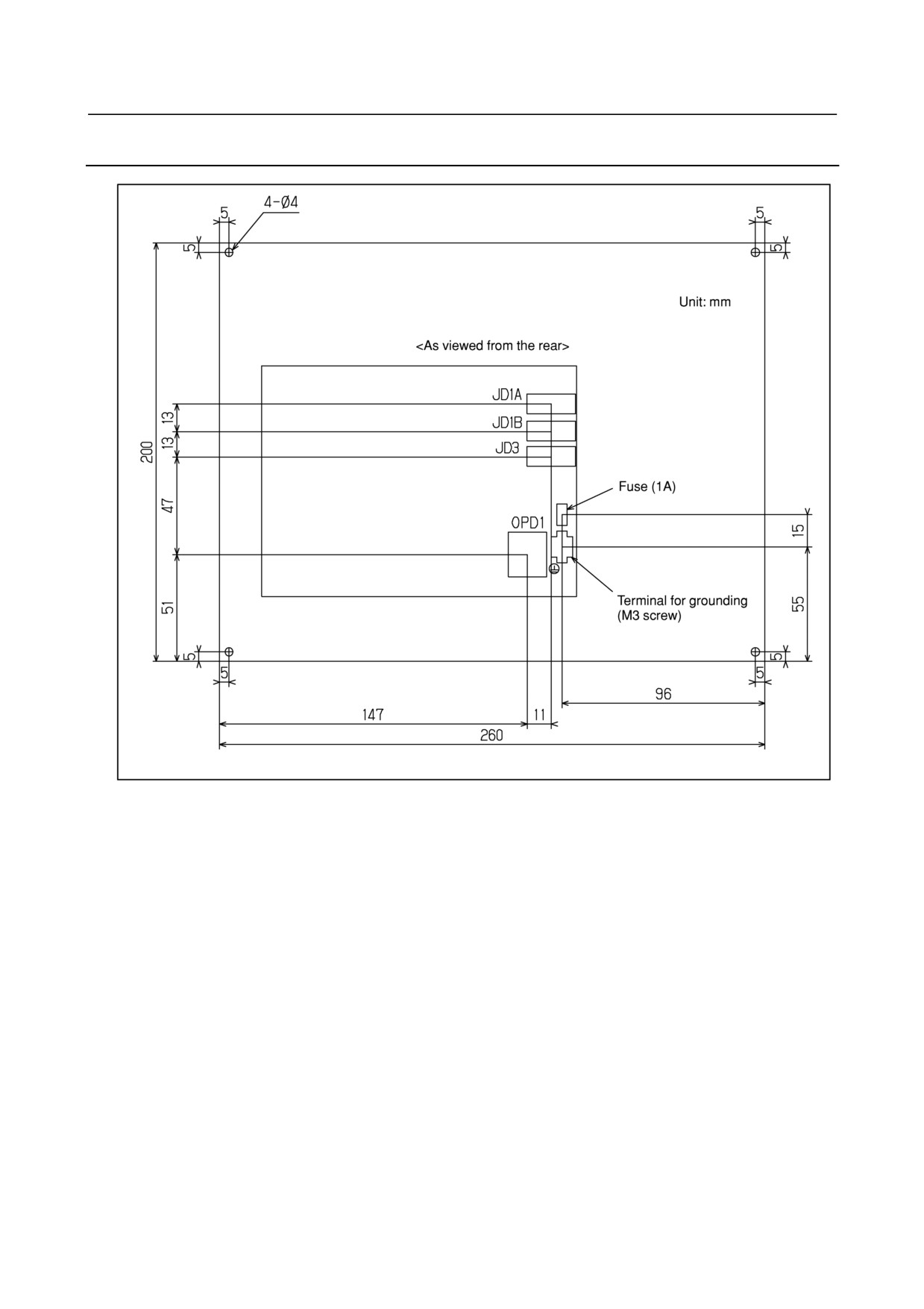
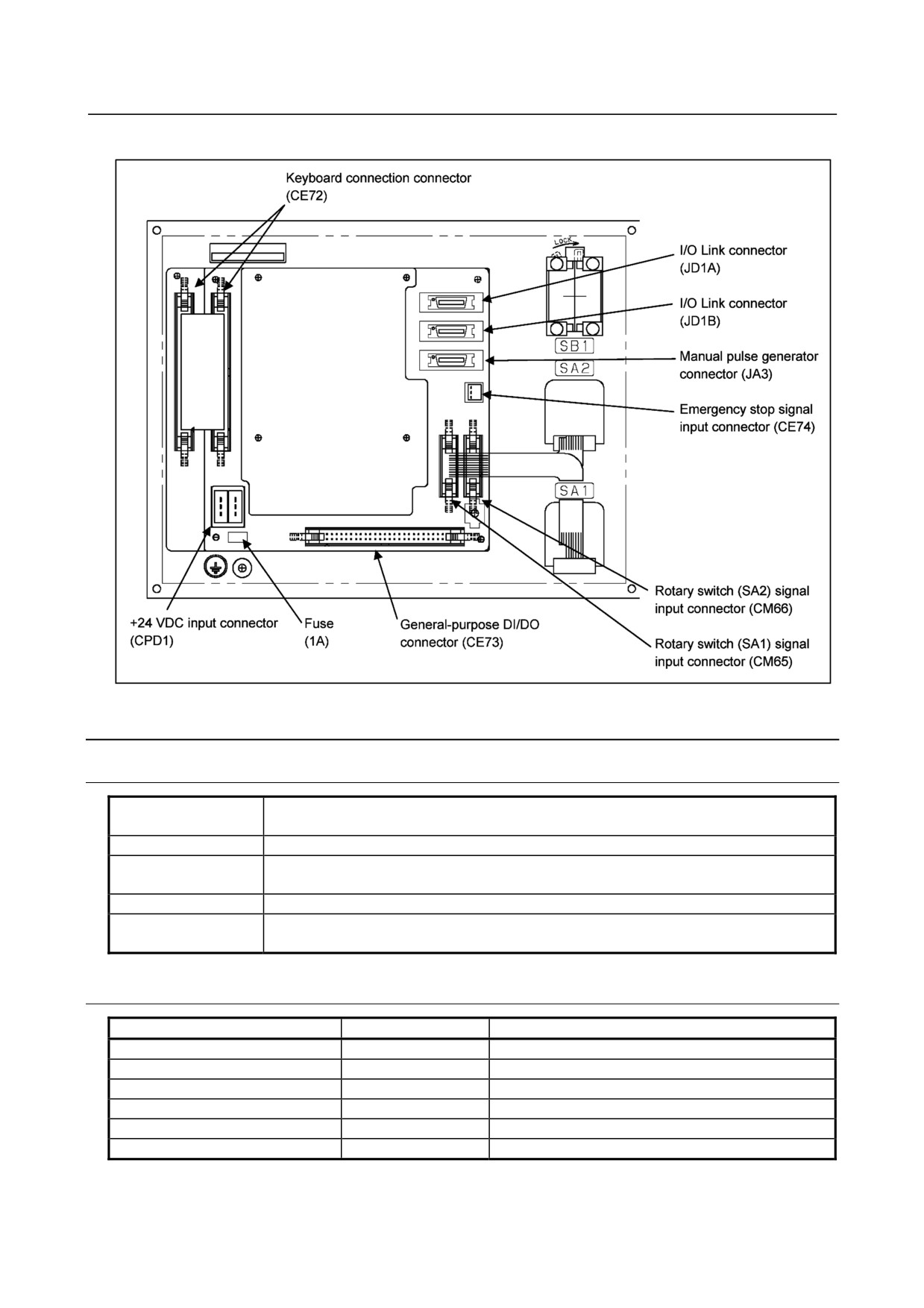
9.10.9 Connector Layout of the Small Machine Operator's Panel
- 278 -
B-64303EN/03
9.CONNECTION OF I/O Link SLAVE DEVICES
Connector Layout of the small machine operator's panel B
9.10.10 Specifications
9.10.10.1 Environmental requirement
Temperature around a
At operation
0°C to 55°C
unit
Storing or transporting
-20°C to 60°C
Temperature variance
Max.
1.155°C/min
Humidity
Normally
75% or less (Relative humidity)
Short time (Within one month
95% or less (Relative humidity)
Vibration
Operating
0.5G or less
Atmosphere
Normal FA atmosphere (Consult us when using the system under environments with
higher degree of dust, coolant, or organic solution.)
9.10.10.2 Order specification
Name
Specification
Remarks
Small machine operator's panel
A02B-0299-C152#M
M series, 3-keystroke support model
Small machine operator's panel
A02B-0299-C152#T
T series, 3-keystroke support model
Small machine operator's panel B
A02B-0309-C151#M
M series, 3-keystroke support model
Small machine operator's panel B
A02B-0309-C151#T
T series, 3-keystroke support model
Transparent keysheet
A02B-0299-K210
Three transparent keysheets
Fuse (Spare part)
A02B-0815-K001
1A
- 279 -
9.CONNECTION OF I/O Link SLAVE DEVICES
B-64303EN/03
9.10.10.3 Operator's panel specification
Item
Specification
Remarks
Keyswitches of machine
30 keys
Matrix DI
operator's panel
LED
Green
Supplied with 21 key switches
Override rotary switch
2
Gray code output (with a parity bit)
Emergency stop switch
1
Number of Contact : 4 (Contact a × 2, Contact b × 2)
M3.5 Screw
MPG interface
Max. 3 units
Interface to CNC
FANUC I/O Link connection
9.10.10.4 Power supply specification
Item
Specification
Remarks
24VDC ±10% (from Power connector CPD1, including
0.4A
Including all DI consumption
momentary values)
Momentary values and ripples are also included in ±10%.
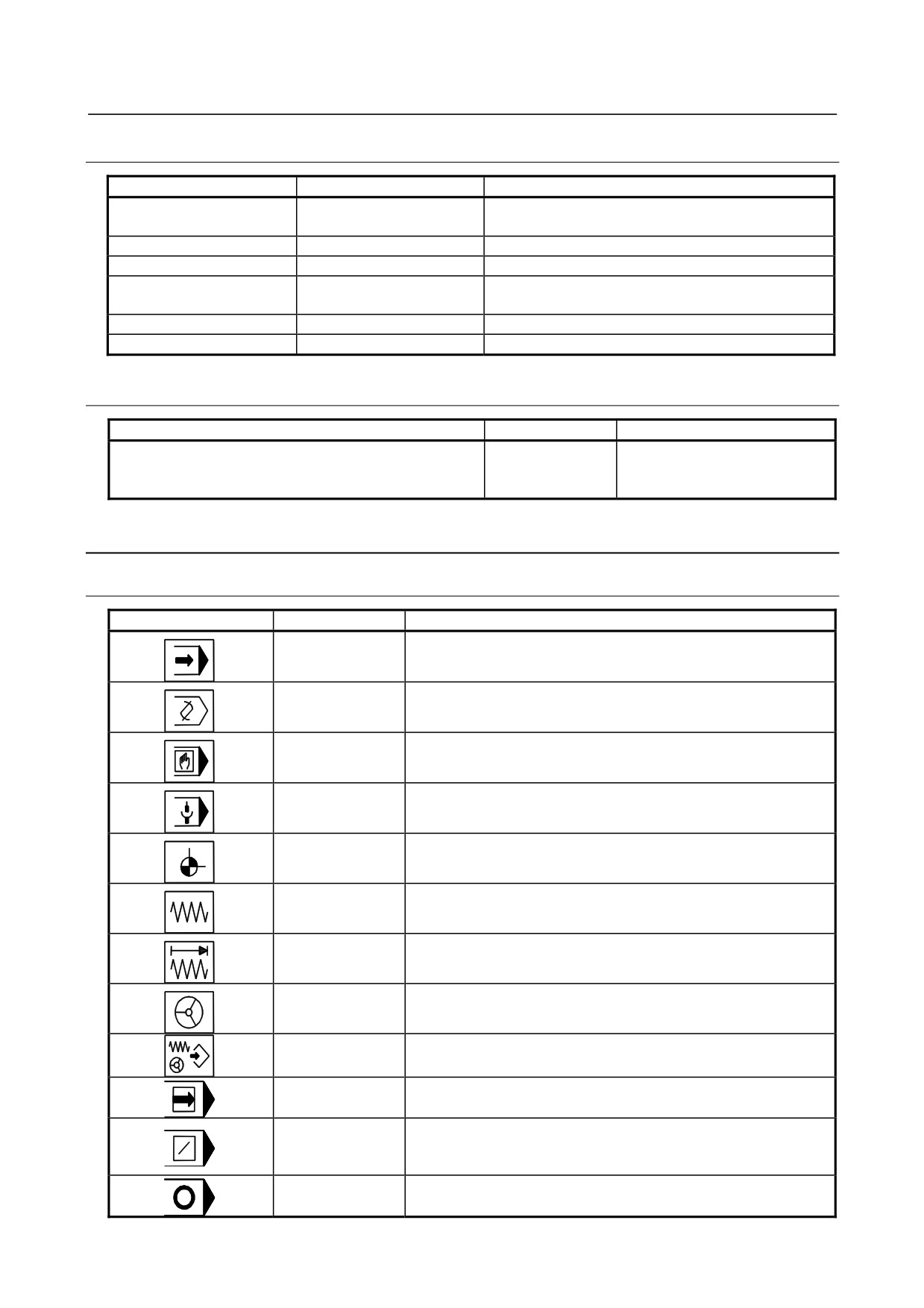
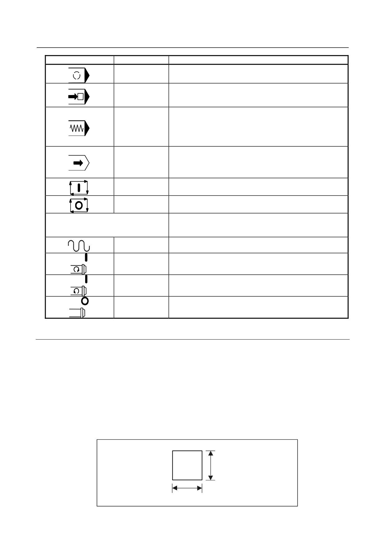
9.10.11 Key Symbol Indication on Machine Operator's Panel
9.10.11.1 Meaning of key symbols
Symbol indication
English
Meaning of key
AUTO
AUTO mode selection signal; Sets automatic operation mode.
EDIT
EDIT mode selection signal; Sets program edit operation mode.
MDI
MDI mode selection; Sets MDI mode.
REMOTE
DNC operation mode; Sets DNC operation mode.
REF
Reference position return mode selection; Sets reference position
return mode.
JOG
JOG feed mode selection; Sets jog feed mode.
INC
Step feed mode selection; Sets step feed mode.
HANDLE
Manual handle feed mode selection; Sets manual handle feed
mode.
TEACH
Teach-in jog (reach-in handle) mode selection signal; Sets teach-in
jog (teach-in handle) mode.
SINGLE
Single block signal; Executes program one by one. This key is
BLOCK
used to check a program.
BLOCK
Block skip: Pressing this button during automatic operation
SKIP
causes the block under execution to stop, skipping to the end of
block (;).
PRG
Program stop (output only); Turns on the LED on the button when
STOP
automatic operation is stopped by M00 specified in the program.
- 280 -
B-64303EN/03
9.CONNECTION OF I/O Link SLAVE DEVICES
Symbol indication
English
Meaning of key
OPT
Optional stop; Stops automatic operation after execution of the
STOP
block of a program where M01 is specified in the program.
RESTART
Program restart; A program may be restart at a block by specifying
the sequence number of the block, after automatic operation is
stopped because of a broken tool or for holidays.
DRY
Dry run; Sets the axis feedrate to the jog federate instead of a
RUN
programmed feedrate when automatic operation is performed by
setting this button to on.
This function is used to check only the movement of the tool when
no workpiece is mounted.
MC
Machine lock; Updates only position display on the screen without
LOCK
making any axis movement, when automatic operation is
performed by setting this button to on.
This function is used to check a program.
CYCLE
Cycle start; Start automatic operation.
START
CYCLE
Cycle stop; Stops automatic operation.
STOP
+X
-X
Manual feed axis selection; Performs jog feed (or step feed) in the
+Y
-Y
direction in which this button is set to ON in jog feed (or step feed)
+Z
-Z
mode.
RAPID
Traverse; Performs jog feed at rapid traverse rate when this button
is set to on.
SPDL
Positive spindle rotation direction; Rotates the spindle motor in the
CW
positive direction.
SPDL
Negative spindle rotation direction; Rotates the spindle motor in
CCW
the negative direction.
SPDL
Spindle stop; Stops the spindle motor rotation.
STOP
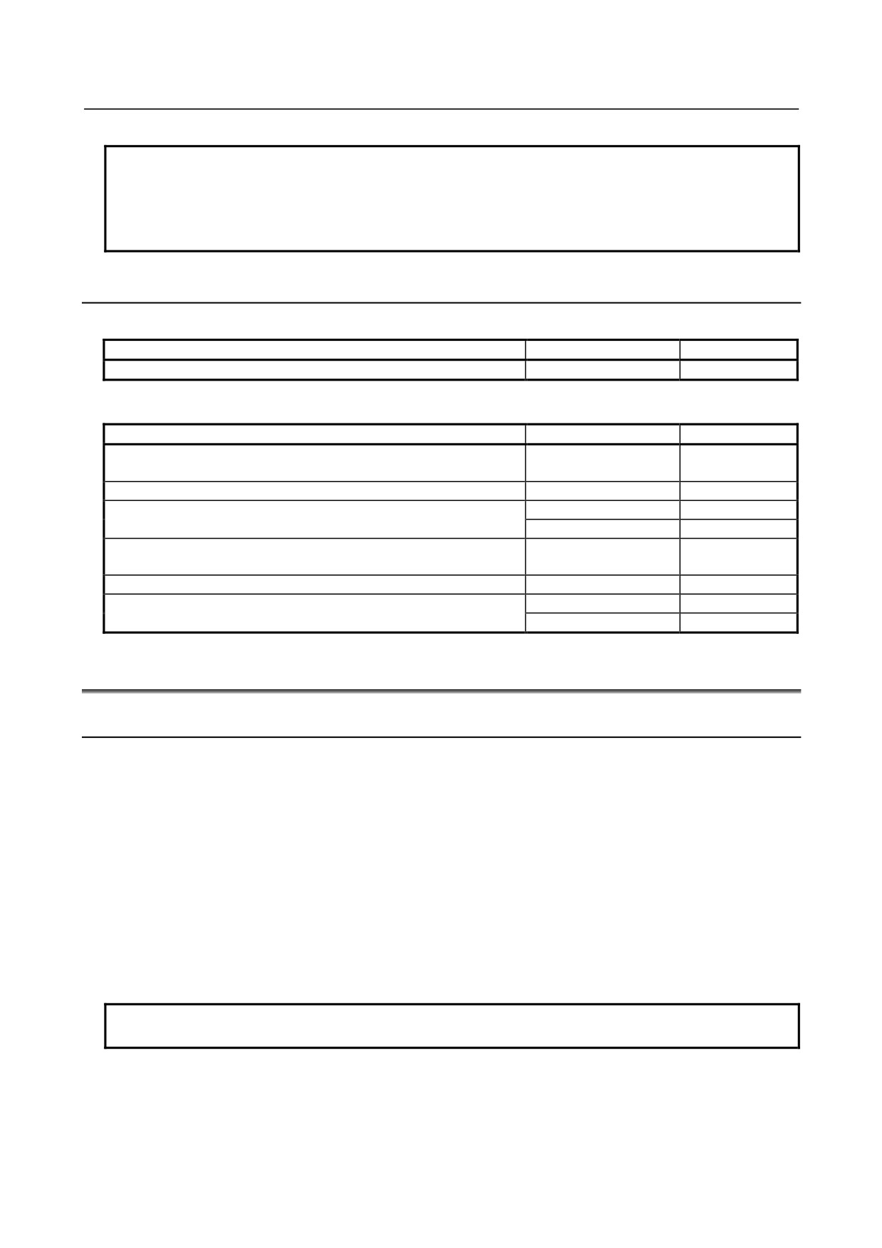
9.10.11.2 Customization of the key sheet
If a customer wishes to partially modify the standard key sheet, he or she can customize the key sheet.
• The machine tool builder prints out the desired key indication on a sticker prepared by the machine
tool builder.
• Apply the sticker on the standard key sheet.
• Remove the screws from the front side, remove the escutcheon, apply a transparent key sheet on the
standard key sheet, taking care not to get dust or air caught between them. Finally, put back the
escutcheon.
• The transparent key sheet is an option.
Specification: A02B-0299-K210 (set of three transparent key sheets)
Size of the sticker
13 mm
13 mm
- 281 -
9.CONNECTION OF I/O Link SLAVE DEVICES
B-64303EN/03
NOTE
If a small machine operator's panel customized in this way is to be maintained
(replaced), the application of the sticker must be performed by the customer.
The customer must prepare a sticker. Once peeled off, the transparent sheet
cannot be reused. Another transparent sheet must be used.
9.10.12 Maintenance Parts
Consumables
Name
Ordering specification
Remarks
Fuse (Operator's panel I/O printed circuit board)
A60L-0001-0290#LM10
Rated: 1A
Items to be repaired
Name
Ordering specification
Remarks
Operator's panel I/O printed circuit board for small machine
A20B-2002-0470
operator's panel
Keyboard printed circuit board for small machine operator's panel
A20B-2004-0220
Small machine operator's panel
A02B-0299-C152#M
M series
A02B-0299-C152#T
T series
Operator's panel I/O printed circuit board for small machine
A20B-2004-0160
operator's panel B
Keyboard printed circuit board for small machine operator's panel B
A20B-2004-0170
Small machine operator's panel B
A02B-0309-C151#M
M series
A02B-0309-C151#T
T series
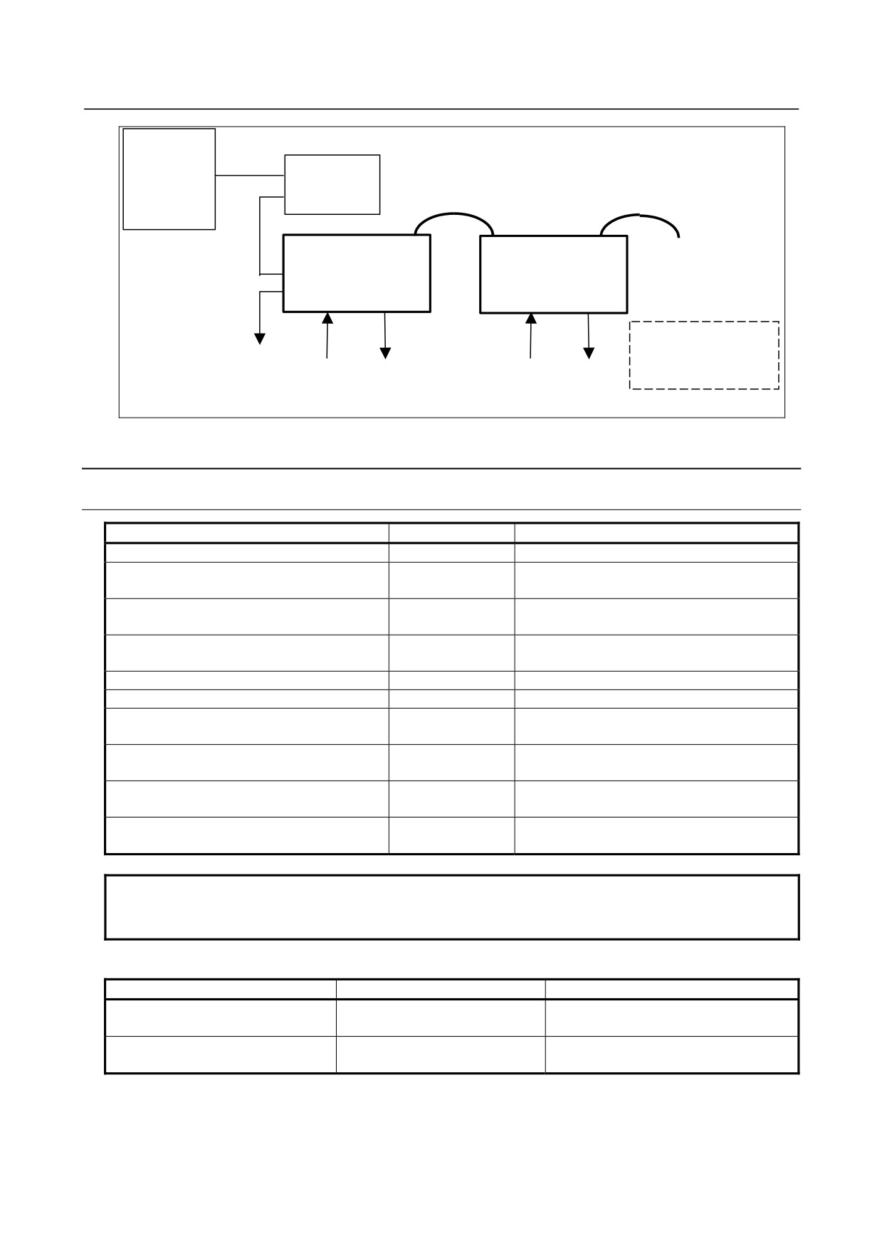
9.11 CONNECTION OF TERMINAL TYPE I/O MODULE
9.11.1 Overview
The terminal type I/O module can be connected to the I/O Link, and the specifications of the existing
connector panel I/O module (Section 9.1) are applicable to the terminal type I/O module. The terminal
type I/O module has the following features:
• Input/output signals are connected on a spring-type terminal block (ferrule terminal block).
• A terminal block can be attached to or detached from the main body of the module.
• An LED for state indication is provided for each I/O signal.
• The digital output circuit is photocoupler-insulated.
• The terminal type I/O module can be installed on the DIN rail.
• By using expansion modules, the maximum number of digital input points can be extended to 96 and
the maximum number of digital output points can be extended to 64.
• An expansion module with a manual pulse generator (MPG) interface is available.
NOTE
Expansion module D has no LED for state indication.
- 282 -
B-64303EN/03
9.CONNECTION OF I/O Link SLAVE DEVICES
CNC, etc.
Operator's
I/O Link
panel I/O
Terminal type I/O
Terminal type I/O
module
module
(Basic module)
(Expansion module)
I/O Link
Up to 3 expansion
modules can be
connected.
Input
Output
Input
Output
24 points
16 points
24 points
16 points
9.11.2 Module Specifications
9.11.2.1 Types of modules
Name
Drawing No.
Specifications
Basic module
A03B-0823-C001
DI/DO : 24/16
DI/DO : 24/16
Expansion module A
A03B-0823-C002
With MPG interface
DI/DO : 24/16
Expansion module B
A03B-0823-C003
Without MPG interface
DO : 16
Expansion module C
A03B-0823-C004
2-A output module
Expansion module D
A03B-0823-C005
Analog input module
Fuse (accessory)
A03B-0823-K001
2 A (for basic module)
Spare terminal block set
Cable-side terminal block set (including each
A03B-0823-K010
(for basic module and expansion module A/B)
of T1 through T4)
Spare terminal block set
Cable-side terminal block set (including each
A03B-0823-K011
(for expansion module C)
of T1 and T2)
Spare terminal block set
Cable-side terminal block set (including each
A03B-0823-K012
(for expansion module D)
of T1 and T2)
Cable length: 100 mm
Inter-module cable A
A03B-0823-K100
Used for expansion module connection
NOTE
A cable-side terminal block is shipped with the main unit. Spare terminal blocks
are used for replacement.
Module specifications (common items)
Item
Specifications
Remarks
Expandable up to 16 units or 1024/1024
Interface with CNC
FANUC I/O Link connection
points as CNC slaves
Interface between basic module and
Up to three expansion modules
Bus connection using a flat cable
expansion modules
connectable per basic module
For the specifications (such as signal input requirements) specific to each module, see the relevant pages
of each item.
- 283 -
9.CONNECTION OF I/O Link SLAVE DEVICES
B-64303EN/03
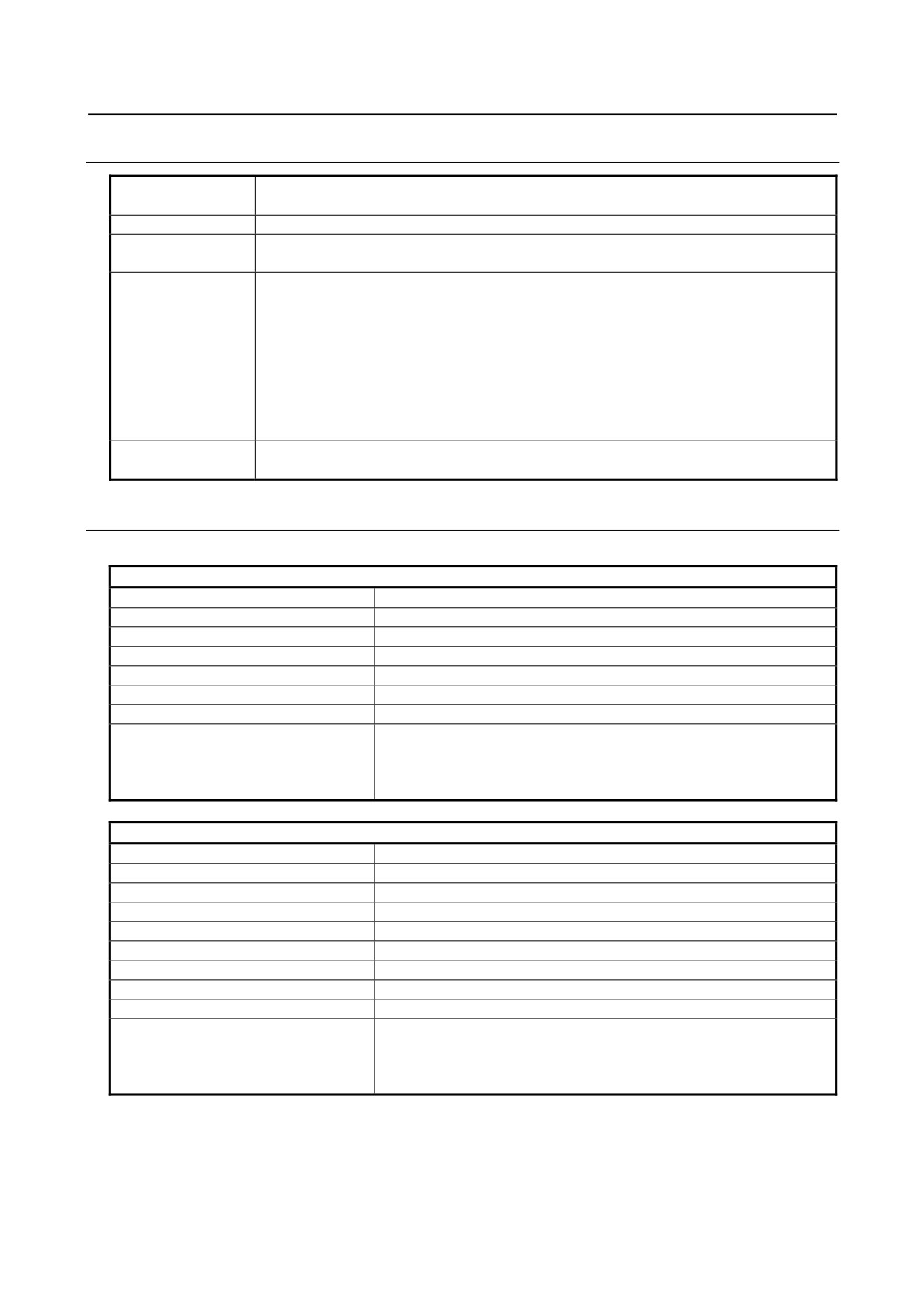
9.11.2.2 Installation conditions
Ambient temperature
Operation: 0°C to 55°C
for the unit
Storage and transportation: -20°C to 60°C
Temperature change
1.1°C/minute maximum
Humidity
Normal condition: 75% or less (relative humidity)
Short term (within one month): 95% or less (relative humidity)
Vibration
Operation: 0.5 G or less
Non-operation: 1.0 G or less
FANUC performs evaluation test under the following conditions:
10 Hz to 58 Hz: 0.075 mm (amplitude)
58 Hz to 500 Hz: 1 G
Vibration direction: X, Y, and Z
Number of sweeps: 10 cycles
Compliance with IEC60068-2-6
Atmosphere
Normal machining factory environment (For use in an environment with relatively high levels
of dust, coolant, organic solutions, and so forth, additional measures are required.)
9.11.2.3 I/O signal specifications
Basic module, expansion modules A and B
Digital input
Number of points
24 points
Common
8 points/common (6 common terminals)
Rated input voltage
24 VDC (+10%, −10%)
Rated input current
7 mA (average)
Polarity
Sink type
ON voltage/current
20 VDC or more, 6 mA or more
OFF voltage/current
8 VDC or less, 1.5 mA or less
Response time
Driver delay time: 50μs(MAX)
In addition, the I/O Link transfer time between the CNC and the I/O
module and the ladder scan cycle time (by the CNC) need to be taken
into account.
Digital output
Number of points
16 points
Common
8 points/common (8 common terminals)
Rated output voltage
12 VDC to 24 VDC (+20%, −15%)
Rated output current
0.2 A/pt
Polarity
Source type
Maximum voltage decrease when ON
0.63 V (load current × 1.25Ω)
Maximum leakage current when OFF
40 μA
Insulation method
Photocoupler insulation
Output protection function
Protection against overheat and overcurrent
Response time
Driver delay time: 50μs(MAX)
In addition, the I/O Link transfer time between the CNC and the I/O
module and the ladder scan cycle time (by the CNC) need to be taken
into account.
- 284 -
B-64303EN/03
9.CONNECTION OF I/O Link SLAVE DEVICES
Expansion module C
Digital output
Number of points
16 points
Common
4 points/common
Rated output voltage
12 VDC to 24 VDC (+20%, −15%)
Rated output current
2 A/pt (4 A/common)
Polarity
Source type
Maximum voltage decrease when ON
0.18 V (load current × 0.09Ω)
Maximum leakage current when OFF
0.1 mA
Insulation method
Photocoupler insulation
Output protection function
Protection against overheat, overcurrent, short-circuiting, and open load
Response time
Driver delay time: 50μs(MAX)
In addition, the I/O Link transfer time between the CNC and the I/O
module and the ladder scan cycle time (by the CNC) need to be taken
into account.
Expansion module D
Analog input
Number of input channels
4 channels
Analog input range
-10 VDC to +10 VDC
Voltage input or current input can
(Input resistance: 4.7 MΩ)
be selected on a
channel-by-channel basis by
-20 VDC to +20 mA
wiring.
(Input resistance: 250Ω)
Digital conversion range
12 bits (binary), two's complement representation
Input/output correspondence
Analog input
Digital output
+10 V
+2000
+5 V or +20 mA
+1000
0 V or 0 mA
0
-5 V or -20 mA
-1000
-10 V
-2000
Resolution
5 mV or 20 μA
Overall precision
Voltage input: ±0.5% (with respect to full scale)
Current input: ±1.0% (with respect to full scale)
Maximum input voltage/current
±15 V/±30 mA
A-D conversion time
2 ms or less
Minimum update period of digital output
Ladder scan period of CNC connected
Number of occupied input/output points
DI = 3 bytes, DO = 2 bytes(NOTE)
NOTE
This module has four analog input channels but has only one 12-bit digital output
channel within the occupied input points (3 bytes). Namely, a channel for
conversion is selected dynamically using a ladder program. Channel switching
DO points for selecting a channel are present in the occupied output points (2
bytes).
(See "Addresses of expansion module D" in Subsection 9.11.6.1, "Address
map".)
- 285 -
9.CONNECTION OF I/O Link SLAVE DEVICES
B-64303EN/03
9.11.2.4 Power supply capacity
Module name
Power supply voltage
Current rating
Basic module
24 VDC ±10%
0.2 A + 7.3 mA × DI
(DI: Number of DI points in the ON state)
Expansion module A, B
Supplied from the basic module
0.1 A + 7.3 mA × DI
(DI: Number of DI points in the ON state)
Expansion module C
Supplied from the basic module
0.1 A
Expansion module D
Supplied from the basic module
0.1 A
9.11.2.5 Heat dissipation
The heat dissipation of a module is the sum of "Basic heat dissipation" in the table below plus the total
obtained by multiplying each of "Heat dissipation per input point" and "Heat dissipation per output point"
in the table below by the number of points that are turned on at the same time.
Basic heat
Heat dissipation
Heat dissipation per output point (W)
Module name
dissipation (W)
per input point (W)
IL: Output load current
Basic module
4.8
0.23
0.04+0.9×IL2
Expansion module A, B
2.4
0.23
0.04+0.9×IL2
Expansion module C
2.4
-
0.04+0.1×IL2
Expansion module D
2.4
-
-
9.11.2.6 Weight
Module name
Weight (g)
Basic module
420
Expansion module A
400
Expansion module B
380
Expansion module C
440
Expansion module D
400
- 286 -