FANUC Series 0i-MODEL D, Series 0i Mate-MODEL D. CONNECTION MANUAL (HARDWARE) - page 8
B-64303EN/03
9.CONNECTION OF I/O Link SLAVE DEVICES
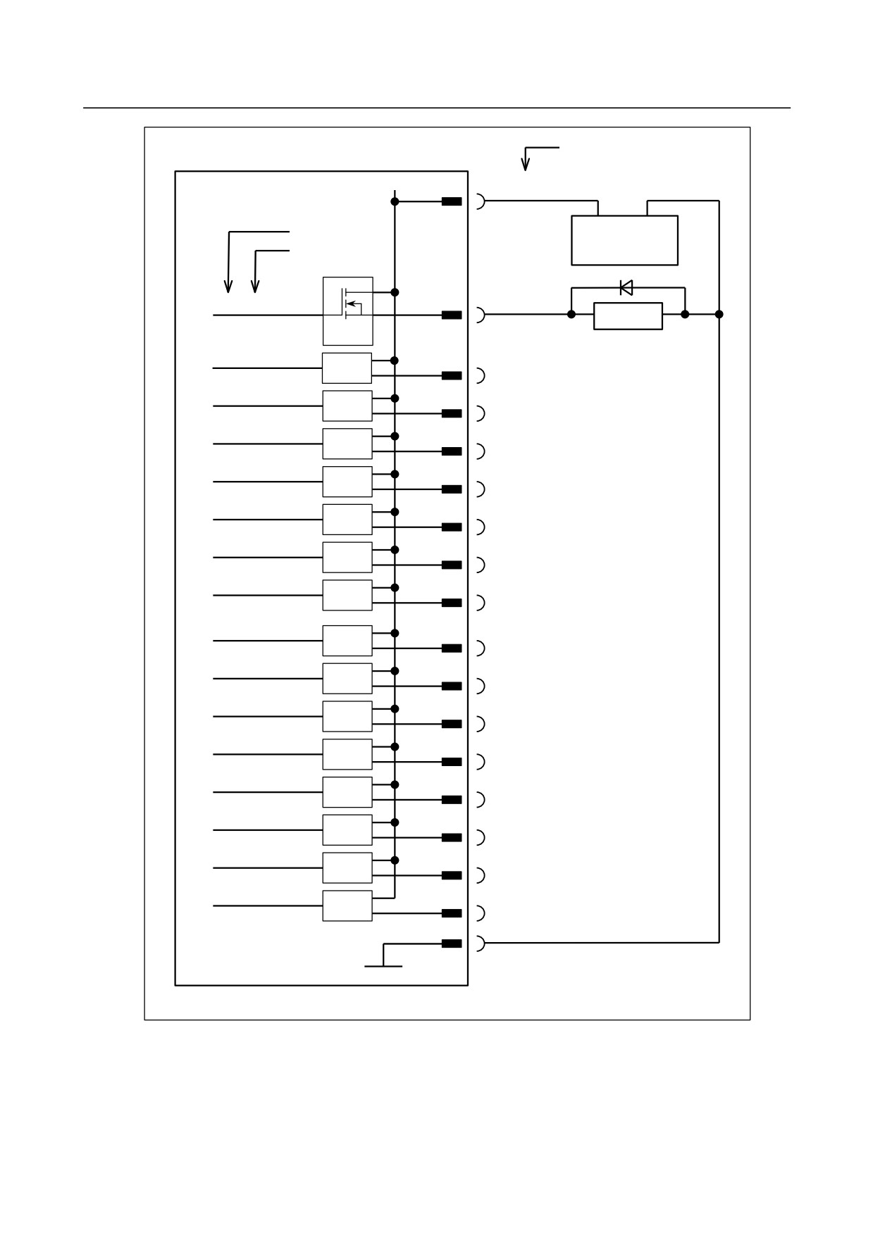
Pin number
DOCOM67
CB162(A07,B07)
+24V
0V
Address number
+24 V stabilized
Bit number
power supply
Yn+6.0
CB162(C07)
Relay
DV
Yn+6.1
DV
CB162(A08)
Yn+6.2
DV
CB162(B08)
Yn+6.3
DV
CB162(C08
Yn+6.4
DV
CB162(A09)
Yn+6.5
DV
CB162(B09)
Yn+6.6
DV
CB162(C09)
Yn+6.7
DV
CB162(A10)
Yn+7.0
DV
CB162(B10)
Yn+7.1
DV
CB162(C10)
Yn+7.2
DV
CB162(A11)
Yn+7.3
DV
CB162(B11)
Yn+7.4
DV
CB162(C11)
Yn+7.5
DV
CB162(A12)
Yn+7.6
DV
CB162(B12)
Yn+7.7
DV
CB162(C12)
CB162(A31,B31,C31,
A30,B30,C30)
0V
- 197 -
9.CONNECTION OF I/O Link SLAVE DEVICES
B-64303EN/03
9.5.8
DI/DO Signal Specifications
This subsection describes the specifications of the DI/DO signals used with the basic module and
expansion module.
DI (input signal specifications)
Number of points
48 points (per module)
Contact rating
30 VDC, 16 mA or more
Leakage current between
1 mA or less (26.4 V)
contacts when opened
Leakage current between
2 V or less (including a cable voltage decrease)
contacts when closed
Delay time
The receiver delay time is 2 ms (maximum).
In addition, [I/O Link transfer time between CNC and I/O module (2 ms
maximum)] + [ladder scan period (depending on CNC)] must be considered.
DO (output signal specifications)
Number of points
32 points (per module)
Maximum load current when ON
200 mA or less including momentary variations
Saturation voltage when ON
1 V (maximum) when the load current is 200 mA
Withstand voltage
24 V +20% or less including momentary variations
Leakage current when OFF
20 µA or less
Delay time
The driver delay time is 50 µs (maximum). In addition, [I/O Link transfer time
between CNC and I/O module (2 ms maximum)] + [ladder scan period
(depending on CNC)] needs to be considered.
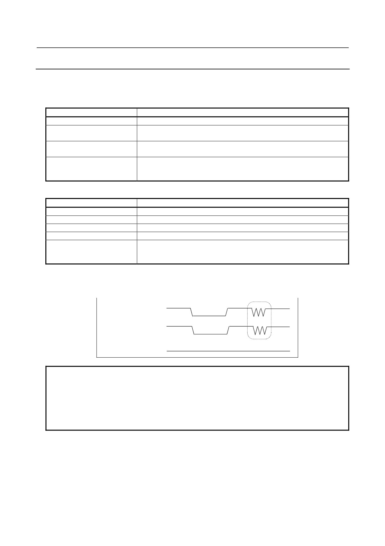
ON/OFF of the power supply (DO common) for DO signals (output signals)
By turning off (opening) the power supply pin (DOCOM) for the DO signals (output signals), all the DO
signals of each module can be turned off at the same time. At this time, the DO state is as shown below.
ON
DOCOM
OFF
DO state when DO is
ON
on in the sequence
OFF
DO state when DO is
ON
off in the sequence
OFF
NOTE
When DO is on in the sequence, the ON/OFF state of DOCOM is directly
reflected in the DO state as indicated above by the dashed box.
The +24 V signal to be supplied to the I/O module must not be turned off during
operation. Otherwise, a CNC communication alarm is issued. Ensure that +24 V
is supplied either when or before the power to the CNC is turned on, and that
+24 V is removed either when or after the power to the CNC is turned off.
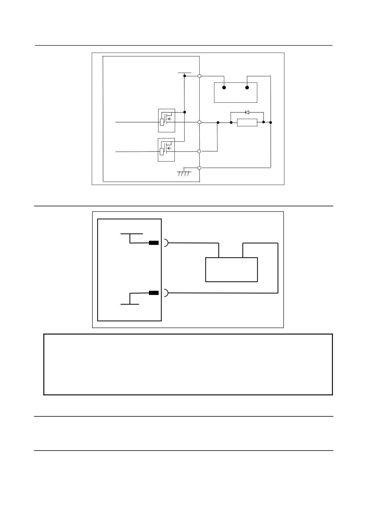
Parallel DO (output signal) connection
A DO load current two times larger can be obtained by connecting DO points in parallel and exercising
ON/OFF control at the same time in the sequence as shown below. Namely, the maximum load current
per DO point is 200 mA, but 400 mA can be obtained by connecting two DO points in parallel and
turning on the two DO points at the same time. In this case, however, the leakage current is also doubled
up to 40 μA when the DO points are turned off.
- 198 -
B-64303EN/03
9.CONNECTION OF I/O Link SLAVE DEVICES
DOCOM
CB150(01),(33)
+24V
0V
+24 V stabilized power supply
Relay
DV
DV
9.5.9
Power Supply Connection
+24V
CB161(A32,B32,C32)
CB162(A32,B32,C32)
+24V
0V
+24V stabilized power supply
CB161(A31,B31,C31, A30,B30,C30)
CB162(A31,B31,C31, A30,B30,C30)
0V
NOTE
The +24 V signal to be supplied to the I/O module must not be turned on/off
during operation.
If the +24V signal is turned off during operation, a CNC communication alarm is
issued. Ensure that +24 V is supplied either when or before the power to the
CNC is turned on, and that +24 V is removed either when or after the power to
the CNC is turned off.
9.5.10 Manual Pulse Generator Connection
See Subsection 9.2.15, "Manual Pulse Generator Connection".
9.5.11 Cable Length for Manual Pulse Generator
See Subsection 9.2.16, "Cable Length for Manual Pulse Generator".
- 199 -
9.CONNECTION OF I/O Link SLAVE DEVICES
B-64303EN/03
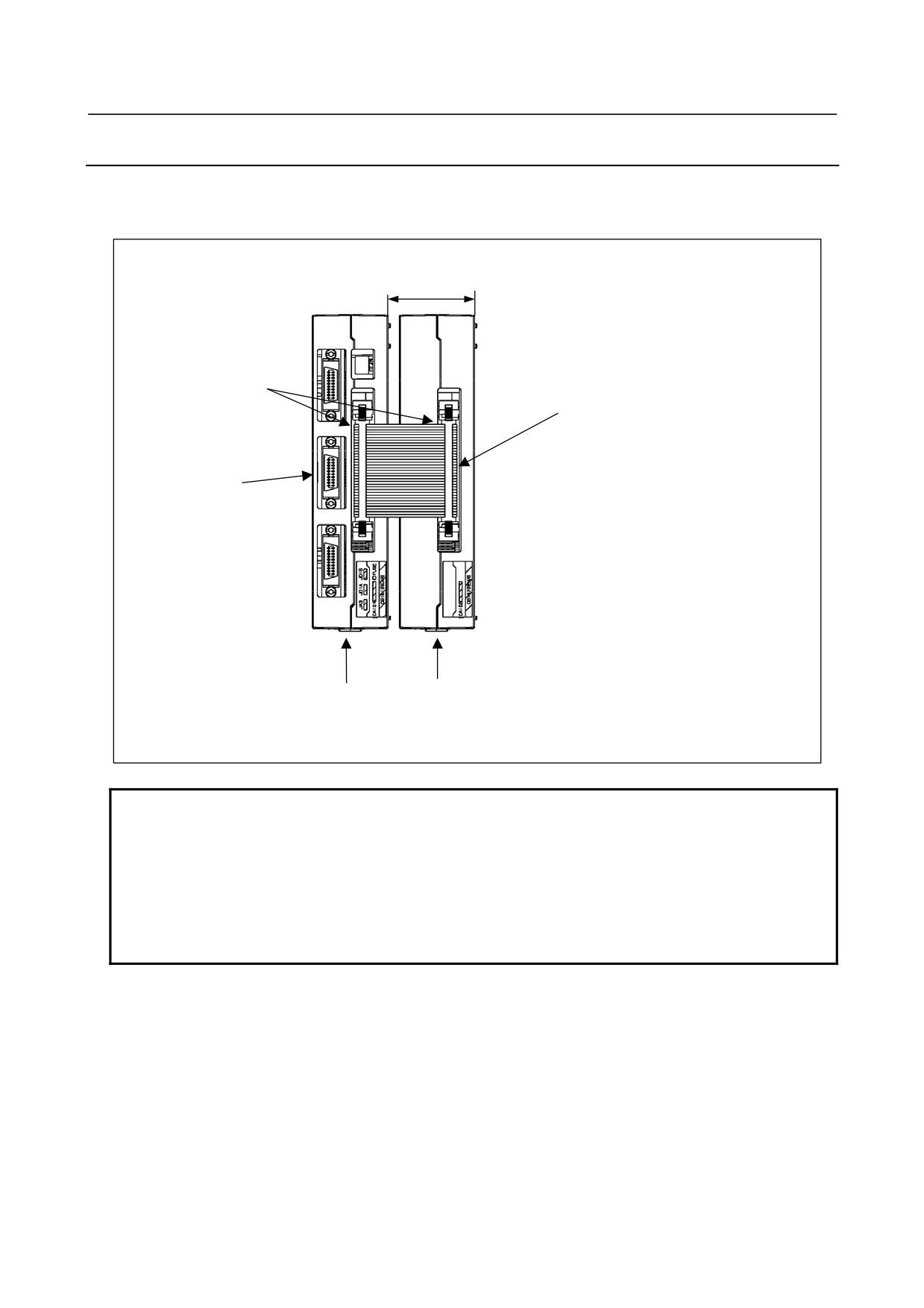
9.5.12 Connection between Modules
Connect the basic module with an expansion module by using a 34-pin flat cable. At this time, install an
expansion module on the right side of the basic module to prevent the I/O Link connector from being
covered by the flat cable.
40 mm
A1 pin mark
34-pin flat cable
I/O Link connector
Flat cable-side connector
Hirose Electric: HIF3BA-34DA-2.54R
Module-side connector
Hirose Electric: 3BA-34PA-2.54DS, or
Yamaichi Denki: FAP-3403-1202-0BS
Basic module
Expansion module
Front view
NOTE
When installing a flat cable, ensure that all pins are connected on a one-to-one
basis.
The modules must be spaced at least 40 mm apart.
In this case, the length of the flat cable is about 35 mm. When the modules are
separated furthermore, the length of the flat cable is:
35 mm + (module spacing - 40 mm)
Note, however, that the maximum allowable flat cable length is 300 mm.
- 200 -
B-64303EN/03
9.CONNECTION OF I/O Link SLAVE DEVICES
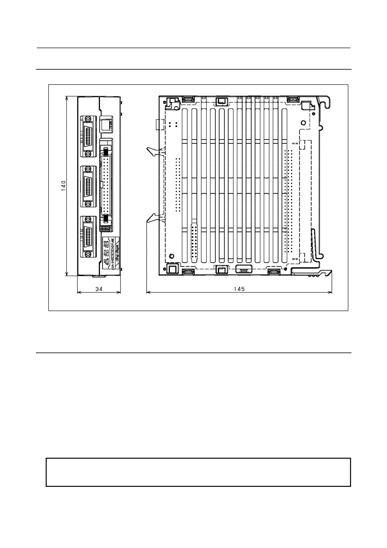
9.5.13 Unit Dimensions
The basic module and expansion module have the same dimensions.
Weight: Basic module
280 g
Expansion module
210 g
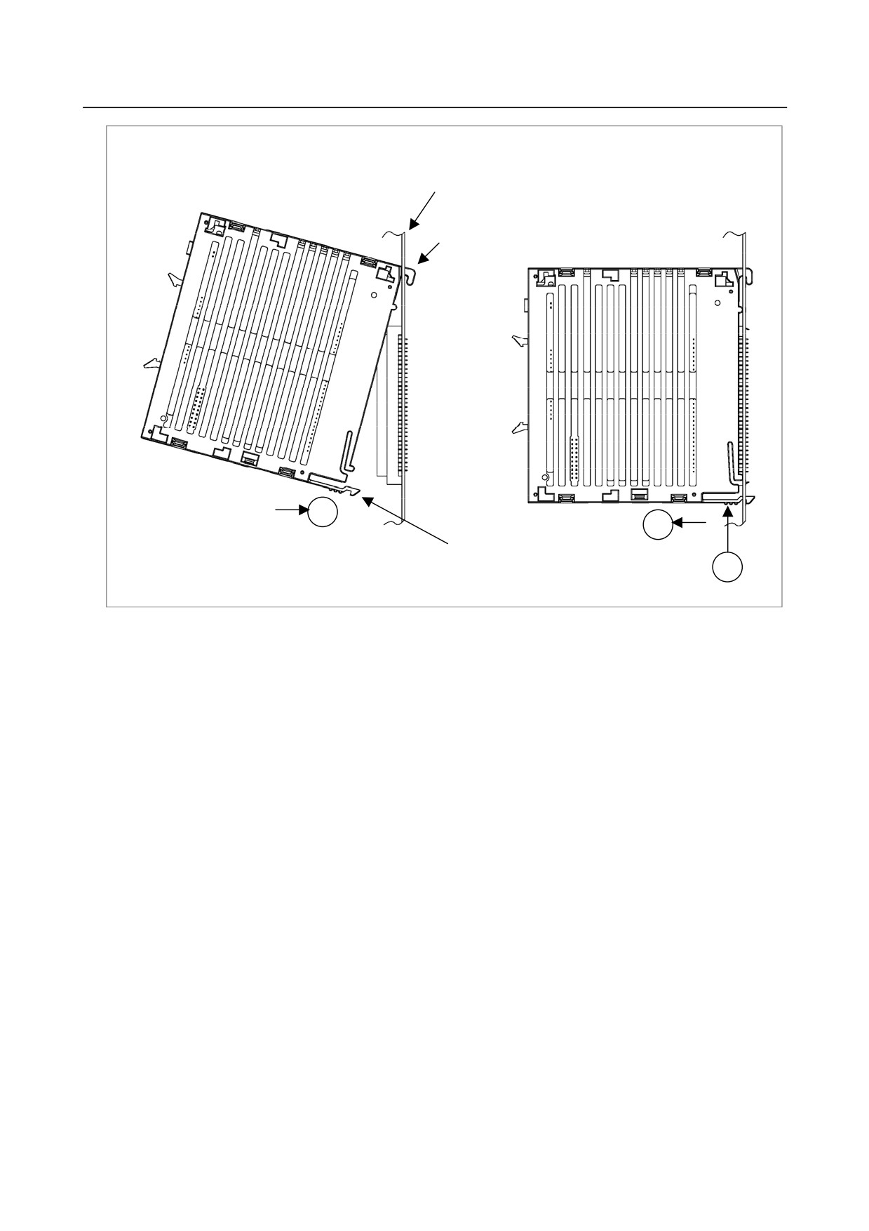
9.5.14 Mounting the Module
Mounting the module
1. Insert the hook of the module into the square hole located at the upper part of the connector panel
printed circuit board.
2. Using the hook as a fulcrum, push the module in the direction of A and mate the module's connector
with the connector on the printed circuit board.
3. Push the stopper into the square hole located at the lower part of the connector panel printed circuit
board until it clicks into place.
Dismounting the module
1. Press point B of the stopper.
2. Using the hook as a fulcrum, pull the lower part of the module in the direction of C.
NOTE
When mounting and dismounting a module, hold the module by its top and
bottom surfaces. Avoid applying force to the sides (where slits are provided).
- 201 -
9.CONNECTION OF I/O Link SLAVE DEVICES
B-64303EN/03
Connector panel PC board
Hook
A
C
Stopper
B
- 202 -
B-64303EN/03
9.CONNECTION OF I/O Link SLAVE DEVICES
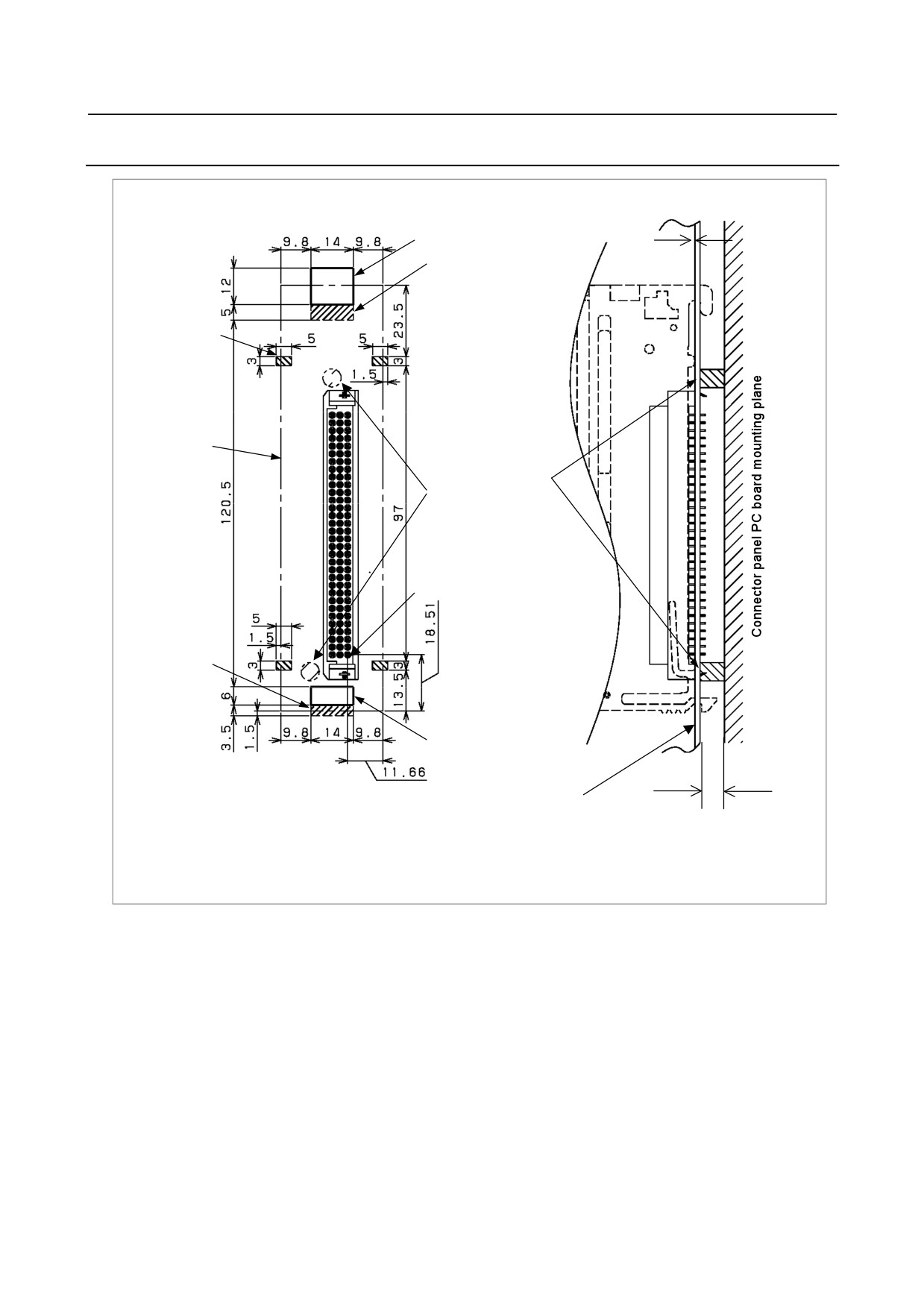
9.5.15 Connector Panel Printed Circuit Board
PC board thickness: 1.7±0.1mm
Square hole (14×12), R1
Printing prohibited
area on solder side
(14×5)
Printing
prohibited area
on component
side (4 - 5×3)
I/O module
mounting area
Provide pedestals on
(component
solder side to
mounting
prevent warpage at
prohibited)
I/O module insertion
time
MRF-96MD
A1 pin
Printing
prohibited area
on solder side
(14×3)
Square hole (14×6), R1
Connector panel PC board
Provide a clearance of at least
6 mm.
- 203 -
9.CONNECTION OF I/O Link SLAVE DEVICES
B-64303EN/03
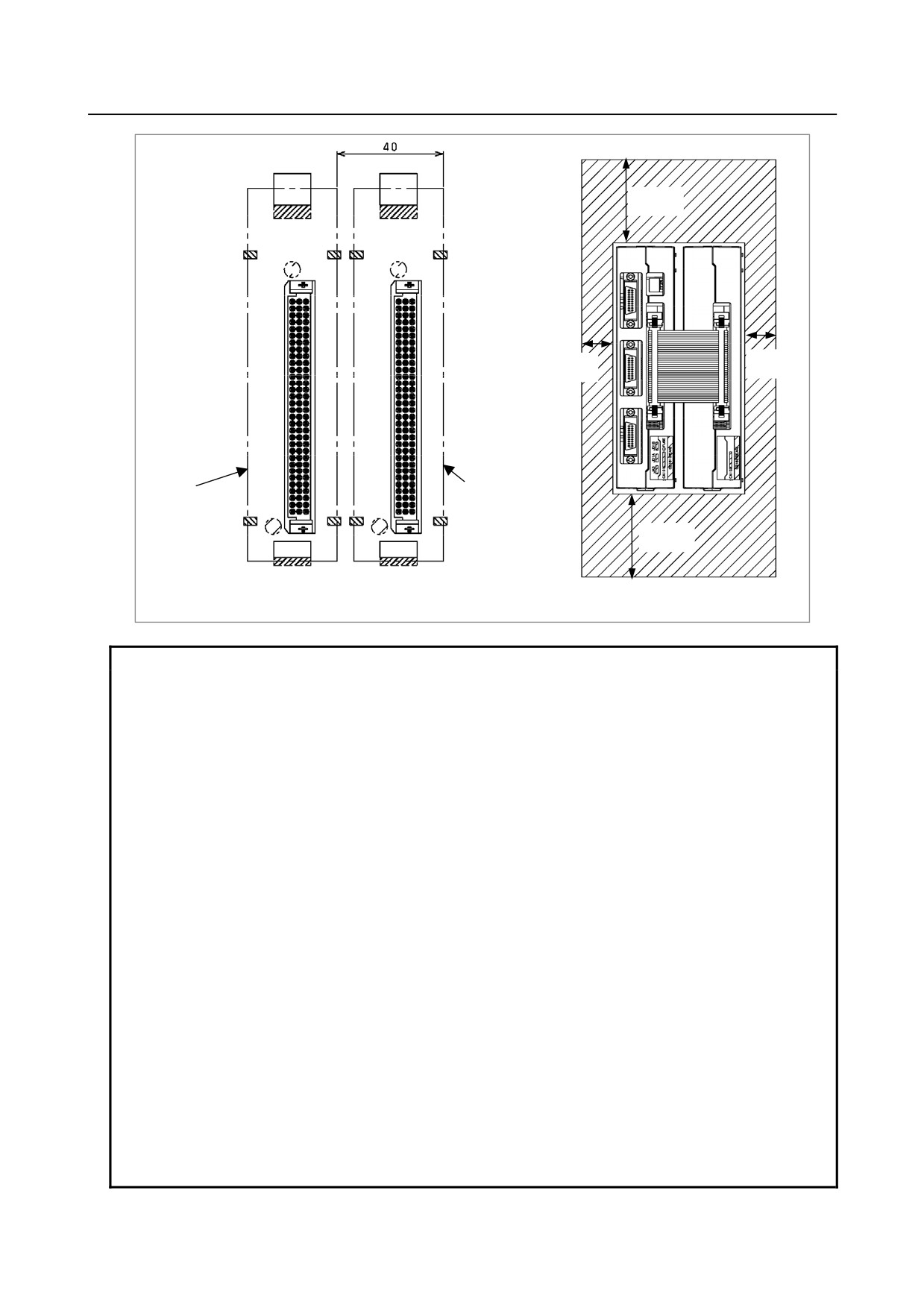
50mm
10mm
10mm
Basic
Expansion module
module
50mm
When two modules are placed side by side, the
modules must be spaced at least 40 mm apart.
NOTE
1
To ensure adequate ventilation within an I/O module, allow a clearance of 50
mm or more above and below the module and a clearance of 10 mm or more on
the left and right sides. Never place a device that generates a large amount of
heat below an I/O module.
2
To the front panel of an I/O module, the cables for the I/O Link and manual pulse
generator are connected.
For cabling, allow a clearance of about 70 mm at the front of an I/O module.
3
Space the basic module and expansion module at least 40 mm apart from each
other.
4
An I/O module is secured to the connector panel by inserting the hook into a
hole on the connector panel as with the current distribution I/O module. Allow a
clearance for hooking on the rear side of the connector panel.
5
For securing an I/O module, four printing prohibited areas are provided on the
surface of the connector panel, and a printing prohibited area is also provided
beside the upper and lower square holes on the rear side.
6
When mounting the basic module and expansion module side by side, ensure
that the basic module is mounted on the left side when viewed from the I/O Link
connector.
7
When inserting an I/O module into the connector panel, provide pedestals at
positions nearest to the connector of the connector panel to support the top and
bottom areas of the connector from the rear side to protect the connector panel
from being warped.
8
Ensure that the thickness of the connector panel printed circuit board is 1.7 mm
±0.1 mm.
- 204 -
B-64303EN/03
9.CONNECTION OF I/O Link SLAVE DEVICES
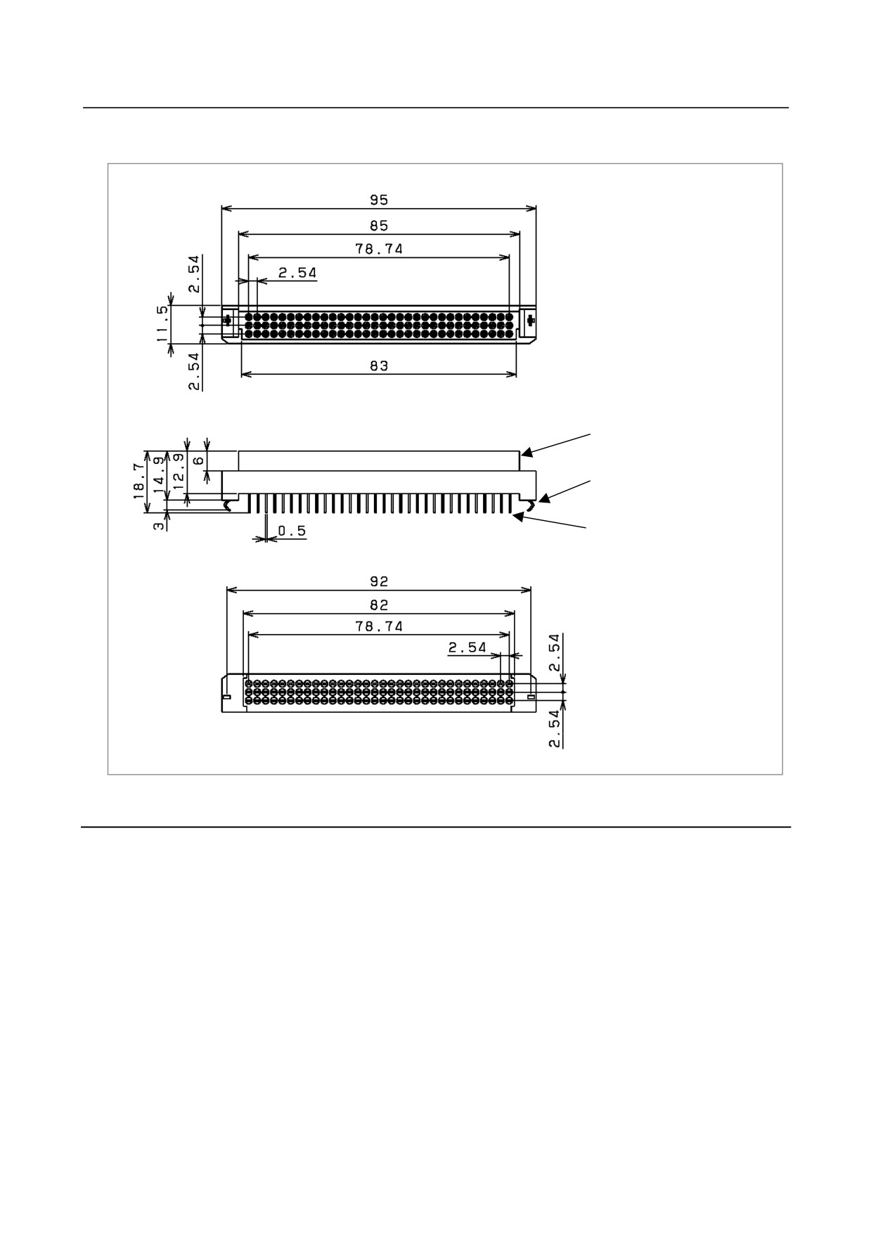
Dimensions of the connector (MRF-96FD) for the connector panel printed circuit board
(Part order specification drawing number: : A03B-0815-K030)
<1>
<2>
<3>
Unit: mm
<1> Insulator
<2> Locking hardware
<3> Contact
9.5.16 Other Notes
DO signal reaction to a system alarm
There is a possibility that the I/O module will not operate normally due to a failure of CNC or I/O Link
slave module, or abnormally power supply voltage. To prevent accidents even in this case, design the
machine to operate safely by making a safety circuit outside the I/O module.
The circuit of this I/O module is designed so that all DO signals are turned off if a system alarm is
occurred in the CNC which controls the I/O module, or if a power of the CNC or the I/O module is turned
off. However, it cannot be guaranteed that DO signals of the I/O module will certainly be turned off.
Therefore, manage signals related to safety by making a safety circuit outside this I/O module.
- 205 -
9.CONNECTION OF I/O Link SLAVE DEVICES
B-64303EN/03
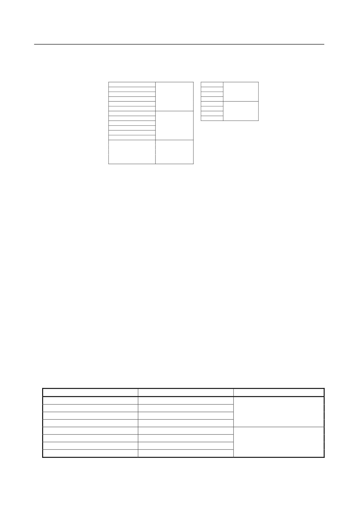
Address allocation
For the connector panel I/O module, I/O addresses are mapped as follow:
DI space map
DO space map
Xm
Yn
Xm + 1
Yn + 1
Basic module
Xm + 2
Basic module
Yn + 2
Xm + 3
Yn + 3
Xm + 4
Yn + 4
Xm + 5
Yn + 5
Expansion module
Xm + 6
Yn + 6
Xm + 7
Yn + 7
Xm + 8
Expansion module
Xm + 9
Xm + 10
Xm + 11
Xm + 12 (for 1st MPG)
Xm + 13 (for 2nd MPG)
Basic module
Xm + 14 (for 3rd MPG)
Xm + 15 (for DO alarm
detection)
Each of Xm and Yn represents the start address of the module on the I/O Link.
Basically, I/O module type-2 is allocated a group of DI addresses (16 bytes) and a group of DO addresses
(8 bytes). Add or remove expansion module hardware as required. The reason is explained below.
The MPG interface (MPG counter) occupies a DI space from Xm+12 to Xm+14. These addresses are
fixed regardless of whether an expansion module is used, and Xm+12 to Xm+14 must be allocated as a
DI work area to enable the use of an MPG. Therefore, when using an MPG, allocate DI addresses in units
of 16-byte groups. The CNC directly processes the value of the MPG counter. So, ensure that the ladder
does not use this area.
DI address Xm+15 is used to detect an overheating alarm issued for a cause such as overcurrent of the IC
used for a DO driver. Address Xm+15 is fixed regardless of whether an expansion module is used. This
address must be allocated as a work area before this address can be used.
For the reason mentioned above, allocate DI addresses for I/O module type-2 in units of 16-byte groups.
DO (output signal) alarm detection
The DO driver of the basic module and expansion module A/B has a function for detecting a load
overcurrent and its temperature. If an accident such as the connecting of the cable to ground causes an
abnormal increase in the load current or in the DO driver temperature, a protection circuit, which is
provided for each DO driver (1 byte), is activated and keeps the 1-byte DO signal in the OFF state until
the cause of the problem is eliminated. Even in this case, the CNC and I/O module continue operation
with no alarm issued. However, the DI address (Xm+15) identifies the DO driver that has detected the
alarm. The table below indicates the correspondence between the DI address (Xm+15) bits and the DO
addresses. Bit value "1" of the DI address (Xm+15) indicates that the corresponding DO driver has
detected an alarm. If a DO alarm is issued, troubleshooting and recovery can be enhanced by checking the
contents of the Xm+15 area with the DGN screen of the CNC or by performing Xm+15 alarm processing
in advance with the ladder.
Alarm detection address and bit
DO address
Location
Xm+15.0
Yn+0
Basic module
Xm+15.1
Yn+1
Xm+15.2
Yn+2
Xm+15.3
Yn+3
Xm+15.4
Yn+4
Expansion module
Xm+15.5
Yn+5
Xm+15.6
Yn+6
Xm+15.7
Yn+7
- 206 -
B-64303EN/03
9.CONNECTION OF I/O Link SLAVE DEVICES
9.6
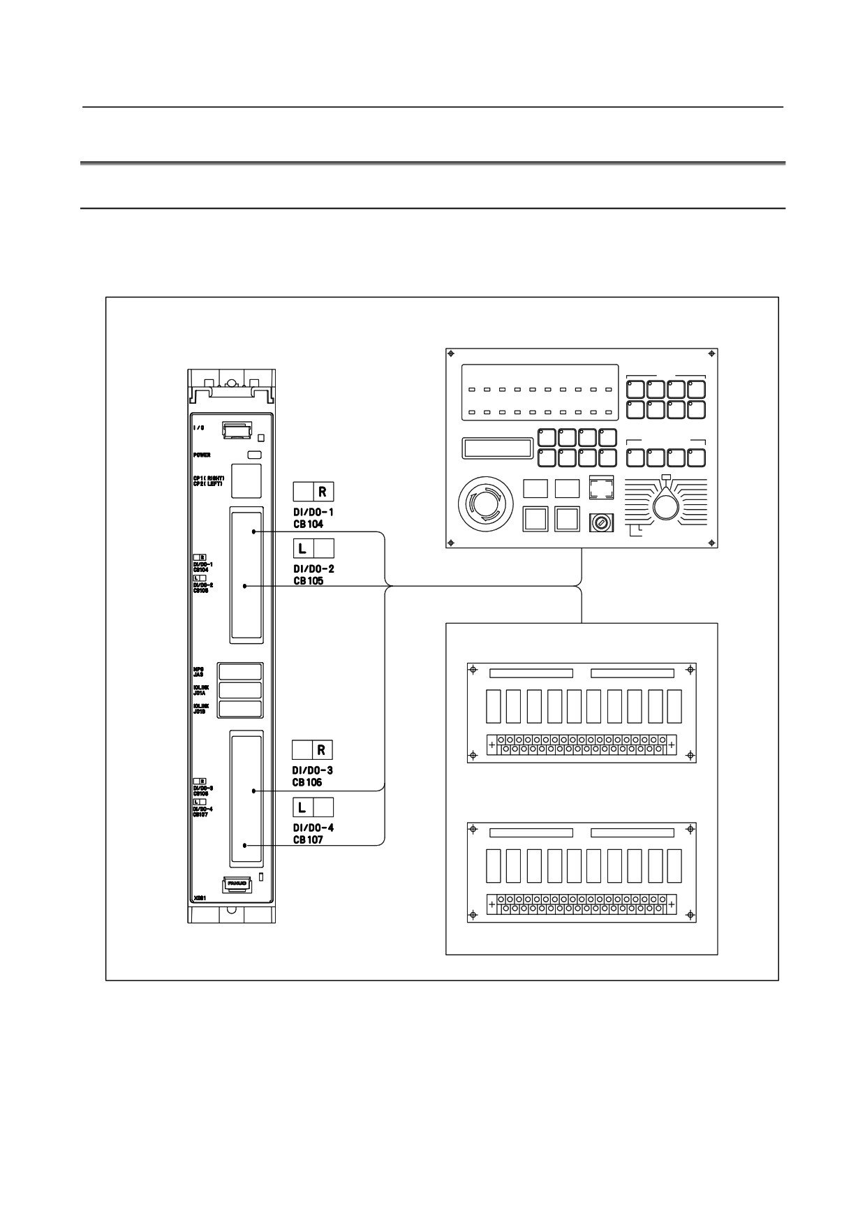
CONNECTION OF I/O UNITS FOR 0i
9.6.1
Overview
With the I/O unit for 0i, up to 96 DI points and up to 64 DO points can be used.
I/O Link is used to connect to controls. For the connection method, see Subsection 8.2.1.
For the I/O unit for 0i, it is necessary to perform I/O Link assignment.
Machine operator's panel
I/O unit for 0i
Power magnetic
panel circuit
- 207 -
9.CONNECTION OF I/O Link SLAVE DEVICES
B-64303EN/03
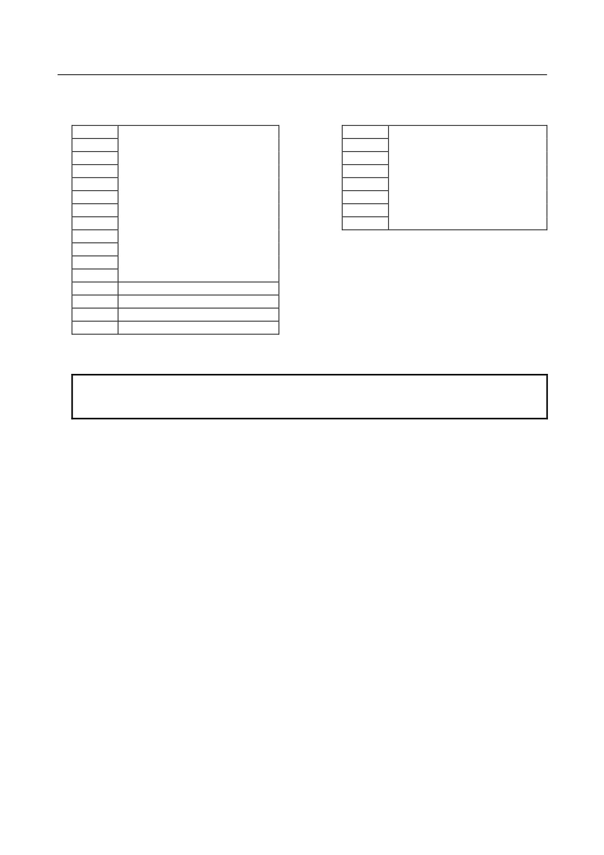
Built-in I/O assignment
DI space map
DO space map
X0
DI 96 points
Y0
DO 64 points
X1
Y1
X2
Y2
X3
Y3
X4
Y4
X5
Y5
X6
Y6
X7
Y7
X8
Module name: CM08O
X9
X10
X11
X12
First MPG
X13
Second MPG
X14
Third MPG
X15
DO alarm detection
Module name: CM16I
NOTE
Since readout from a manual pulse generator (X12 to X14) is directly performed
by the CNC, only the above assignment must be performed by the PMC.
If the number of DI/DO points is not sufficient, external I/O units such as the dispersed I/O can be added
using the FANUC I/O Link.
A MIL-compatible ribbon cable connector is used as the interface connector of the I/O unit for 0i to
simplify connection to the connector panel.
The connector can also be used for the Series 0i Mate.
DO signal reaction to a system alarm
There is a possibility that the I/O unit will not operate normally due to a failure of CNC or I/O Link slave
module, or abnormally power supply voltage. To prevent accidents even in this case, design the machine
to operate safely by making a safety circuit outside the I/O unit.
The circuit of this I/O unit is designed so that all DO signals are turned off if a system alarm is occurred
in the CNC which controls the I/O unit, or if a power of the CNC or the I/O unit is turned off. However, it
cannot be guaranteed that DO signals of the I/O unit will certainly be turned off. Therefore, manage
signals related to safety by making a safety circuit outside this I/O unit.
DO (output signal) alarm detection
The DO driver of the I/O unit for 0i is capable of detecting an overcurrent and measuring its own
temperature. If an accident, such as the connecting of the cable to ground, causes an abnormal increase in
the load current or in the driver temperature, a protection circuit, which is provided for each DO driver (1
byte), is activated and keeps the DO signal for the relevant 1 byte in the OFF state until the cause of the
problem is eliminated. Even if this occurs, the CNC and I/O module continue operating. The DI address
(Xm+15) identifies the DO driver which has detected the alarm. The following table shows the
correspondence between the DI address (Xm+15) bits and the DO addresses. Bit value "1" indicates that
the corresponding DO driver has detected an alarm. The contents of the Xm+15 area can be checked by
using the DGN screen of the CNC or by performing alarm processing for the area in advance by using
Ladder. This helps alarm detection and recovery.
- 208 -

B-64303EN/03
9.CONNECTION OF I/O Link SLAVE DEVICES
Alarm detection address and bit
DO address
Xm+15.0
Yn+0
Xm+15.1
Yn+1
Xm+15.2
Yn+2
Xm+15.3
Yn+3
Xm+15.4
Yn+4
Xm+15.5
Yn+5
Xm+15.6
Yn+6
Xm+15.7
Yn+7
9.6.2
Cautions
The following cautions must be observed when using I/O signal receivers and drivers for the machine
interface.
DI Signals and Receivers
DI signals are basically of the sink type (a type that drains energy). Some DI signals, however, can be
set to either sink type or source type (a type that supplies energy). See the description of the I/O board
in the following section for details.
A common signal is provided for selectable receivers. Whether the common signal is connected to 0 V
or 24 V determines whether a DI signal is of sink or source type.
A source type DI signal is undesirable from the viewpoint of safety, however, because if the input signal
line is grounded, it will be latched in the same state as that existing when the contact is closed. It is
recommended that all DI signals be set to sink type.
Always connect the common signal to either 0 or 24 V; do not leave it open.
DO Signals and Drivers
The driver of DO signals is source type (a type that supplies energy, non-insulating).
There is a possibility that the I/O unit will not operate normally due to a failure of CNC or I/O Link slave
module, or abnormally power supply voltage. To prevent accidents even in this case, design the machine
to operate safely by making a safety circuit outside the I/O unit.
The circuit of this I/O unit is designed so that all DO signals are turned off if a system alarm is occurred
in the CNC which controls the I/O unit, or if a power of the CNC or the I/O unit is turned off. However, it
cannot be guaranteed that DO signals of the I/O unit will certainly be turned off. Therefore, manage
signals related to safety by making a safety circuit outside this I/O unit.
- 209 -
9.CONNECTION OF I/O Link SLAVE DEVICES
B-64303EN/03
9.6.3
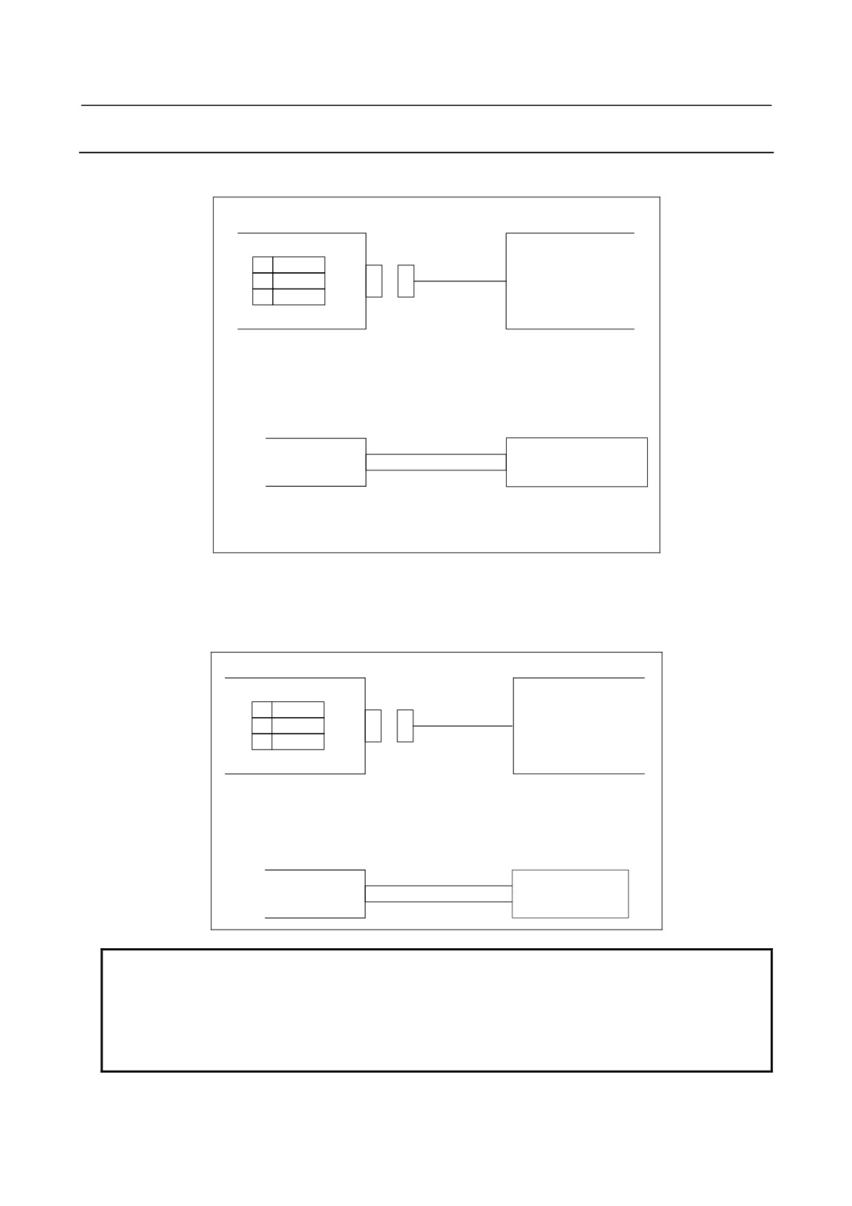
Cable for Power Supply to Control Unit
Supply power to the I/O unit for 0i from external resource.
I/O unit for 0i
External power
CP1
24VDC stabilized
power
1
+24V
2
0V
24VDC ±10%
3
Cable
CP1
AMP Japan
1-178288-3 (housing)
1-175218-5 (Contact)
External power
Select a source that
+24V (1)
meets the external
0V (2)
power terminal.
Recommended cable : A02B-0124-K830 (5m)
(Crimp terminal of size M3 is available on the external power side)
Part of the 24 VDC power input to CP1 can be taken out from CP2 by branching. CP2 should be
connected as shown below. In this case, the rating of the external 24 VDC power supplied to CP1 must
be the sum of the power consumed within the control unit and that supplied to external equipment via
CP2. The maximum capacity of power that can be obtained from a branch is 1.0 A.
I/O unit for 0i
External device
CP2
1
+24V
2
0V
3
Cable
CP2
AMP JAPAN
2-178288-3 (Housing)
1-175218-5 (Contact)
External device
Select a connector that
+24V (1)
matches the pin layout
0V (2)
of the external device.
NOTE
Do not interrupt +24 V supplied to this connector during operation. Otherwise,
an alarm about communication with the CNC is issued.
A voltage of +24 V must not be supplied after power-on of the CNC and +24 V
must not be interrupted before power-off of the CNC. When powering off the
CNC body, be sure to power off the I/O unit for 0i.
- 210 -
B-64303EN/03
9.CONNECTION OF I/O Link SLAVE DEVICES
9.6.4
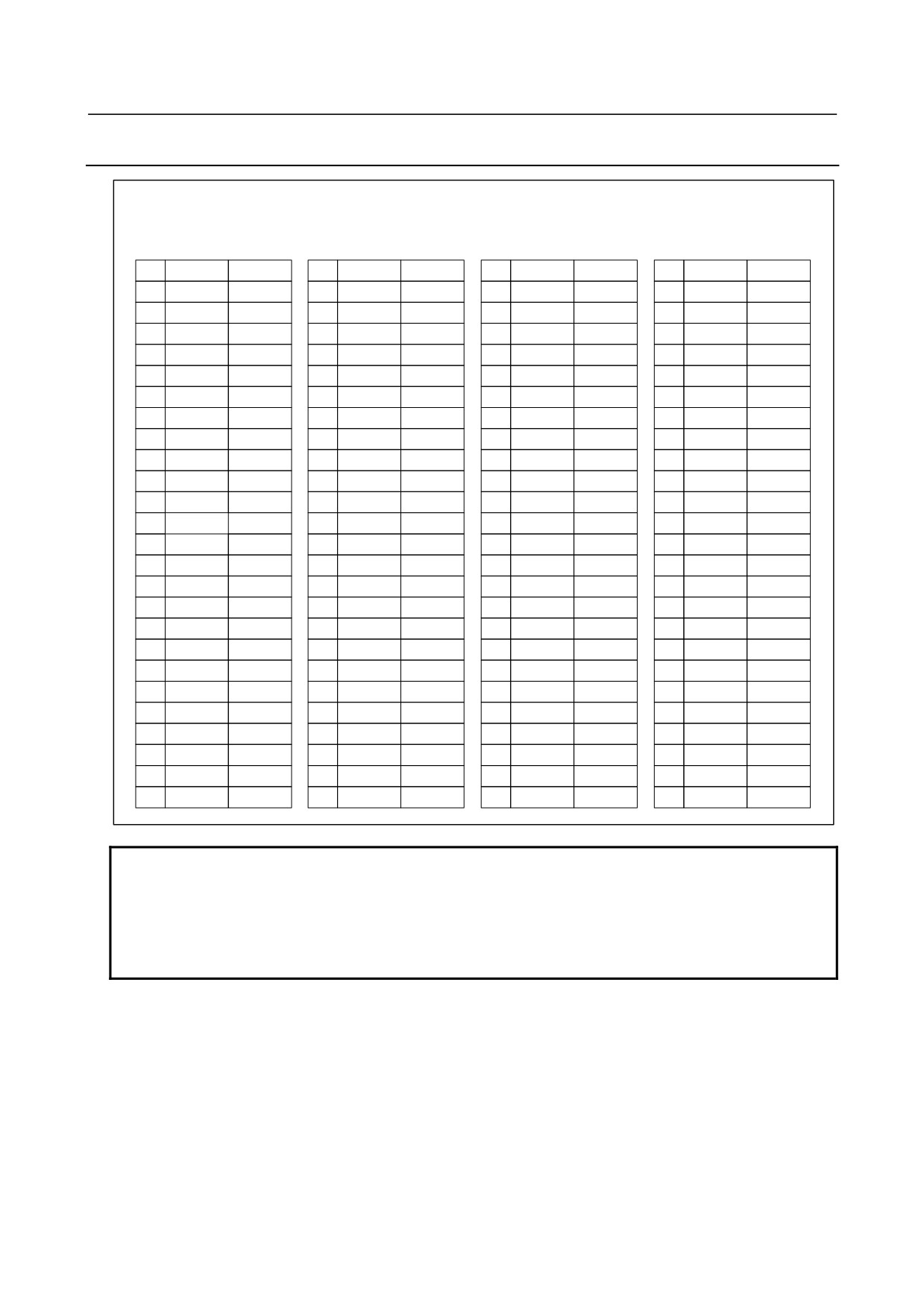
Connector Pin Arrangement
CB104
CB105
CB106
CB107
HIROSE 50PIN
HIROSE 50PIN
HIROSE 50PIN
HIROSE 50PIN
A
B
A
B
A
B
A
B
01
0V
+24V
01
0V
+24V
01
0V
+24V
01
0V
+24V
02
Xm+0.0
Xm+0.1
02
Xm+3.0
Xm+3.1
02
Xm+4.0
Xm+4.1
02
Xm+7.0
Xm+7.1
03
Xm+0.2
Xm+0.3
03
Xm+3.2
Xm+3.3
03
Xm+4.2
Xm+4.3
03
Xm+7.2
Xm+7.3
04
Xm+0.4
Xm+0.5
04
Xm+3.4
Xm+3.5
04
Xm+4.4
Xm+4.5
04
Xm+7.4
Xm+7.5
05
Xm+0.6
Xm+0.7
05
Xm+3.6
Xm+3.7
05
Xm+4.6
Xm+4.7
05
Xm+7.6
Xm+7.7
06
Xm+1.0
Xm+1.1
06
Xm+8.0
Xm+8.1
06
Xm+5.0
Xm+5.1
06
Xm+10.0
Xm+10.1
07
Xm+1.2
Xm+1.3
07
Xm+8.2
Xm+8.3
07
Xm+5.2
Xm+5.3
07
Xm+10.2
Xm+10.3
08
Xm+1.4
Xm+1.5
08
Xm+8.4
Xm+8.5
08
Xm+5.4
Xm+5.5
08
Xm+10.4
Xm+10.5
09
Xm+1.6
Xm+1.7
09
Xm+8.6
Xm+8.7
09
Xm+5.6
Xm+5.7
09
Xm+10.6
Xm+10.7
10
Xm+2.0
Xm+2.1
10
Xm+9.0
Xm+9.1
10
Xm+6.0
Xm+6.1
10
Xm+11.0
Xm+11.1
11
Xm+2.2
Xm+2.3
11
Xm+9.2
Xm+9.3
11
Xm+6.2
Xm+6.3
11
Xm+11.2
Xm+11.3
12
Xm+2.4
Xm+2.5
12
Xm+9.4
Xm+9.5
12
Xm+6.4
Xm+6.5
12
Xm+11.4
Xm+11.5
13
Xm+2.6
Xm+2.7
13
Xm+9.6
Xm+9.7
13
Xm+6.6
Xm+6.7
13
Xm+11.6
Xm+11.7
14
14
14
COM4
14
15
15
15
15
16
Yn+0.0
Yn+0.1
16
Yn+2.0
Yn+2.1
16
Yn+4.0
Yn+4.1
16
Yn+6.0
Yn+6.1
17
Yn+0.2
Yn+0.3
17
Yn+2.2
Yn+2.3
17
Yn+4.2
Yn+4.3
17
Yn+6.2
Yn+6.3
18
Yn+0.4
Yn+0.5
18
Yn+2.4
Yn+2.5
18
Yn+4.4
Yn+4.5
18
Yn+6.4
Yn+6.5
19
Yn+0.6
Yn+0.7
19
Yn+2.6
Yn+2.7
19
Yn+4.6
Yn+4.7
19
Yn+6.6
Yn+6.7
20
Yn+1.0
Yn+1.1
20
Yn+3.0
Yn+3.1
20
Yn+5.0
Yn+5.1
20
Yn+7.0
Yn+7.1
21
Yn+1.2
Yn+1.3
21
Yn+3.2
Yn+3.3
21
Yn+5.2
Yn+5.3
21
Yn+7.2
Yn+7.3
22
Yn+1.4
Yn+1.5
22
Yn+3.4
Yn+3.5
22
Yn+5.4
Yn+5.5
22
Yn+7.4
Yn+7.5
23
Yn+1.6
Yn+1.7
23
Yn+3.6
Yn+3.7
23
Yn+5.6
Yn+5.7
23
Yn+7.6
Yn+7.7
24
DOCOM
DOCOM
24
DOCOM
DOCOM
24
DOCOM
DOCOM
24
DOCOM
DOCOM
25
DOCOM
DOCOM
25
DOCOM
DOCOM
25
DOCOM
DOCOM
25
DOCOM
DOCOM
NOTE
1 The B01 +24 V pins of the connectors (CB104, CB105, CB106, and CB107) are
used for the DI input signals, and which output 24 VDC.
Do not connect +24 V of an external power supply to these pins.
2 Each DOCOM is connected in the printer board. If using the DO signal (Y) of a
connector, be sure to input 24 VDC to each pin of the DOCOM of that connector.
• Connector recommended for use on the cable side
HIF3BB-50D-2.54R (Hirose) : Refer to Appendix C6.
- 211 -
9.CONNECTION OF I/O Link SLAVE DEVICES
B-64303EN/03
9.6.5
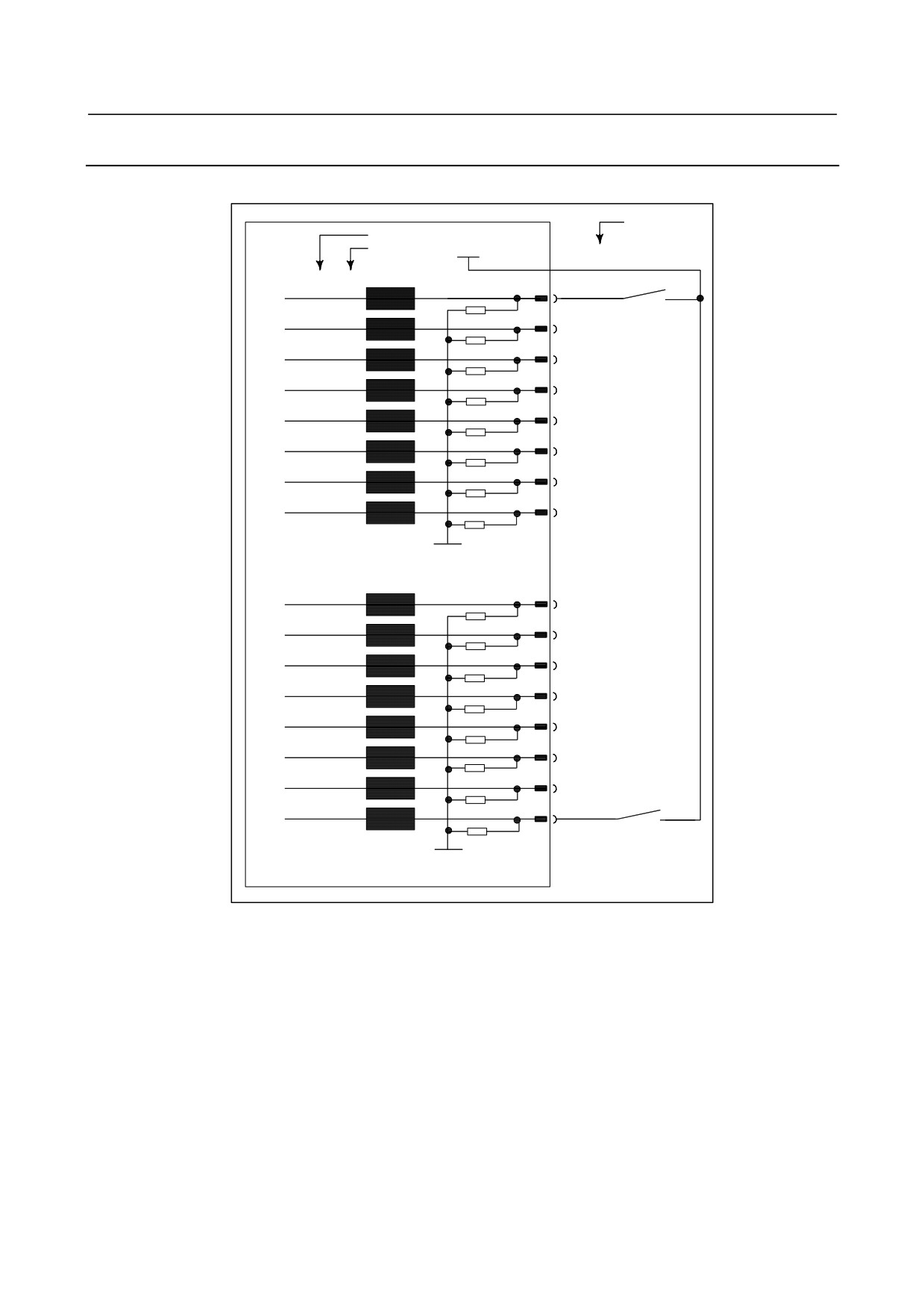
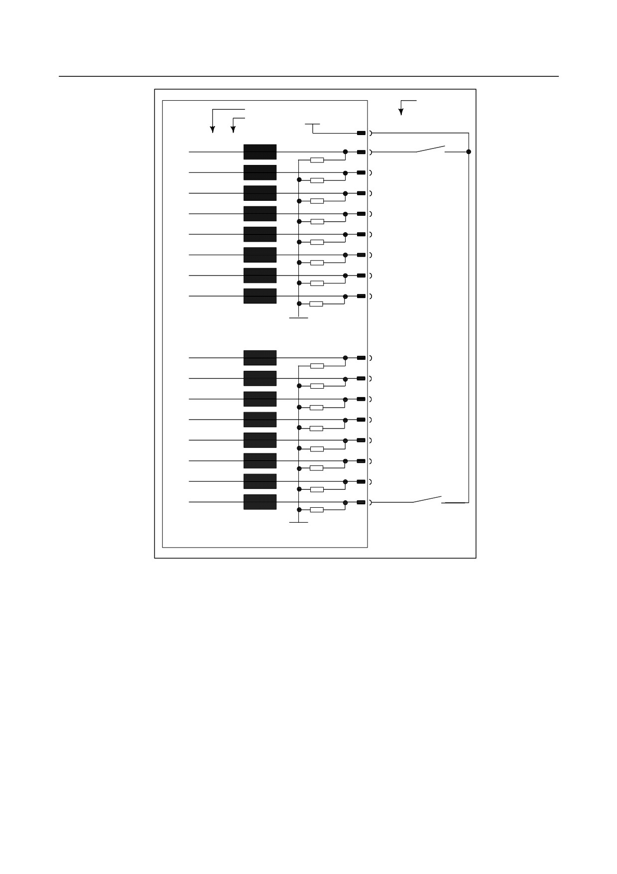
Connecting DI/DO
For example, connecting DI
Terminal
No.
Address No.†
+24V
Bit No.”Ô
†
CB104(B01)
Xm+0.0
CB104(A02)
RV
Xm+0.1
CB104(B02)
RV
Xm+0.2
CB104(A03)
RV
Xm+0.3
CB104(B03)
RV
Xm+0.4
CB104(A04)
RV
Xm+0.5
CB104(B04)
RV
Xm+0.6
CB104(A05)
RV
Xm+0.7
CB104(B05)
RV
0V
Xm+1.0
CB104(A06)
RV
Xm+1.1
CB104(B06)
RV
Xm+1.2
CB104(A07)
RV
Xm+1.3
CB104(B07)
RV
Xm+1.4
CB104(A08)
RV
Xm+1.5
CB104(B08)
RV
Xm+1.6
CB104(A09)
RV
Xm+1.7
CB104(B09)
RV
0V
- 212 -
B-64303EN/03
9.CONNECTION OF I/O Link SLAVE DEVICES
Terminal N
o†
Address No.
+24V
Bit No.”Ô
†
CB104(B01),CB105(B01)
Xm+2.0
CB104(A10)
RV
Xm+2.1
CB104(B10)
RV
Xm+2.2
CB104(A11)
RV
Xm+2.3
CB104(B11)
RV
Xm+2.4
CB104(A12)
RV
Xm+2.5
CB104(B12)
RV
Xm+2.6
CB104(A13)
RV
Xm+2.7
CB104(B13)
RV
0V
Xm+3.0
CB105(A02)
RV
Xm+3.1
CB105(B02)
RV
Xm+3.2
CB105(A03)
RV
Xm+3.3
CB105(B03)
RV
Xm+3.4
CB105(A04)
RV
Xm+3.5
CB105(B04)
RV
Xm+3.6
CB105(A05)
RV
Xm+3.7
CB105(B05)
RV
0V
- 213 -
9.CONNECTION OF I/O Link SLAVE DEVICES
B-64303EN/03
Terminal N
o†
Address No.
+24V
Bit No.”Ô
†
CB106(B01)
Xm+4.0
CB106(A02)
RV
Xm+4.1
CB106(B02)
RV
Xm+4.2
CB106(A03)
RV
Xm+4.3
CB106(B03)
RV
Xm+4.4
CB106(A04)
RV
Xm+4.5
CB106(B04)
RV
Xm+4.6
CB106(A05)
RV
Xm+4.7
CB106(B05)
RV
COM4
CB106(A14)
CB106(A01)
0V
Xm+5.0
CB106(A06)
RV
Xm+5.1
CB106(B06)
RV
Xm+5.2
CB106(A07)
RV
Xm+5.3
CB106(B07)
RV
Xm+5.4
CB106(A08)
RV
Xm+5.5
CB106(B08)
RV
Xm+5.6
CB106(A09)
RV
Xm+5.7
CB106(B09)
RV
0V
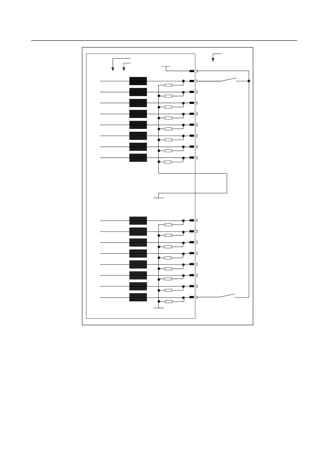
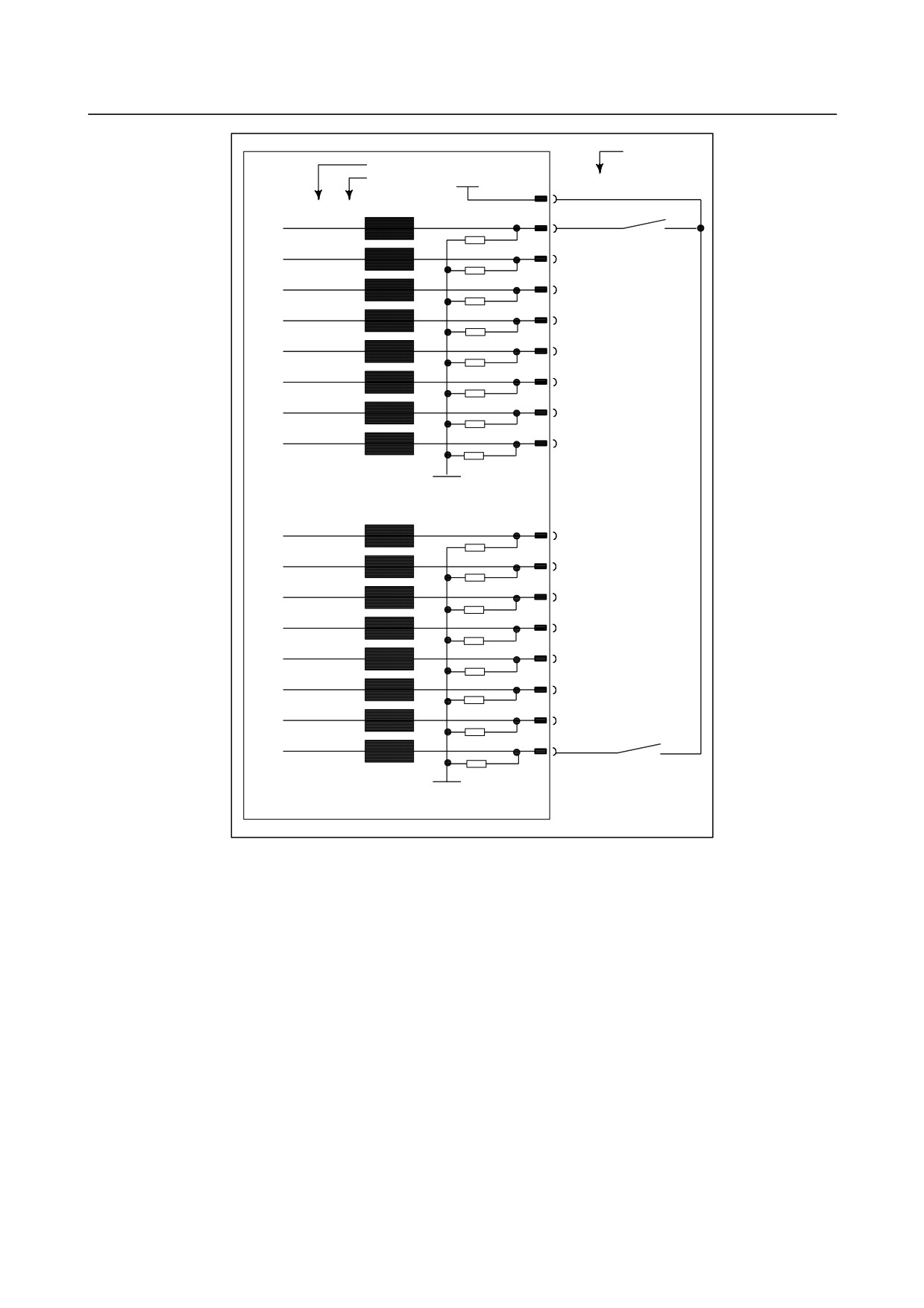
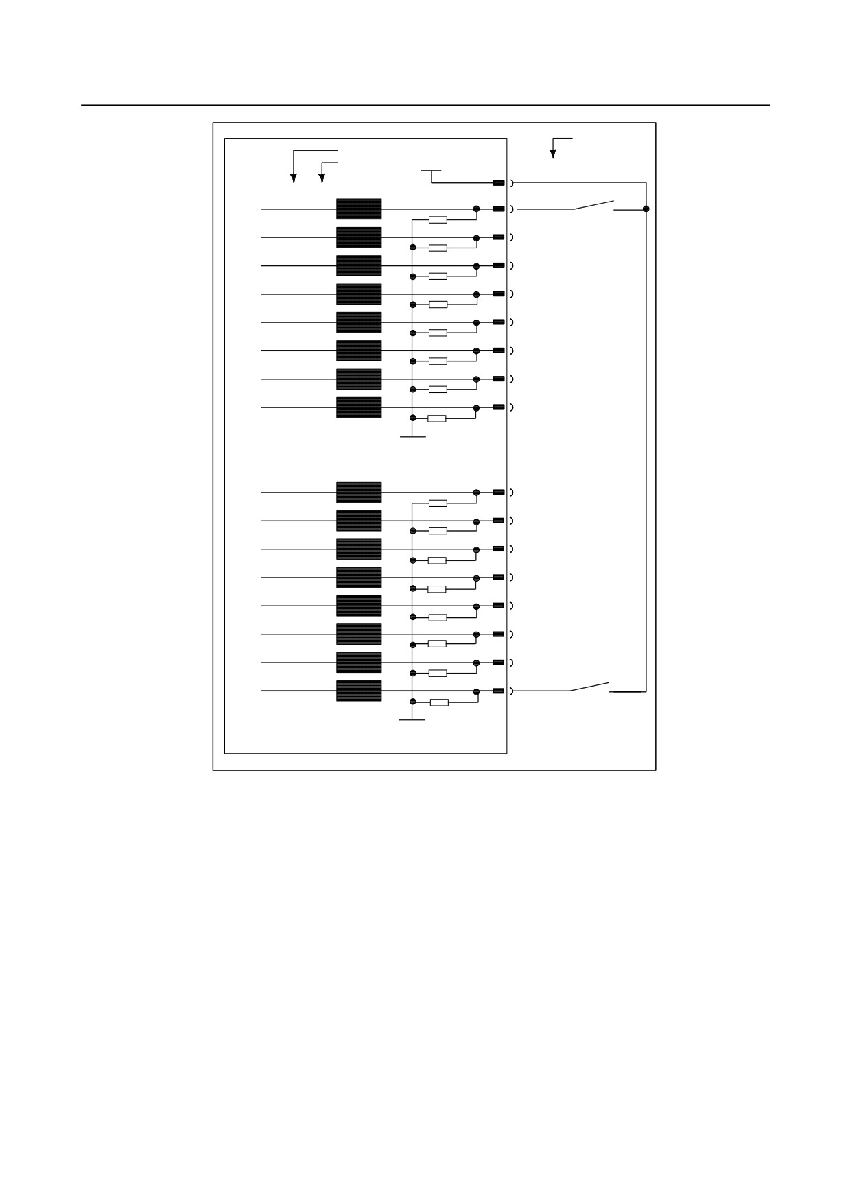
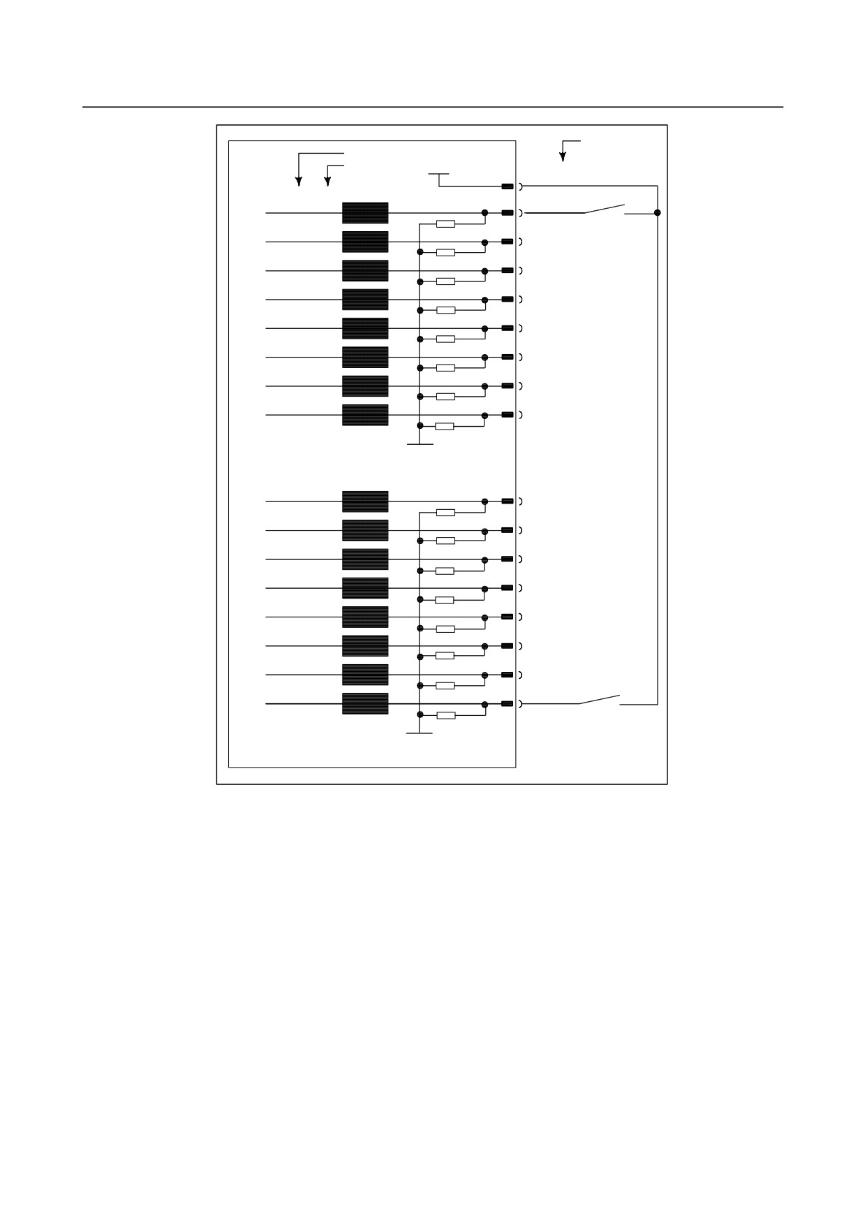
For address Xm+4, either a source or sink type (with a 0- or 24-V common voltage) can be selected.
COM4 must be connected to either 24 or 0 V; never leave it open. From the viewpoint of safety
standards, it is recommended that a sink type signal be used. The above diagram shows an example in
which the signal is of sink type (with a 24-V common voltage).
- 214 -
B-64303EN/03
9.CONNECTION OF I/O Link SLAVE DEVICES
Terminal
No
†
Address No.
+24V
Bit No.”Ô
†
CB106(B01),CB107(B01)
Xm+6.0
CB106(A10)
RV
Xm+6.1
CB106(B10)
RV
Xm+6.2
CB106(A11)
RV
Xm+6.3
CB106(B11)
RV
Xm+6.4
CB106(A12)
RV
Xm+6.5
CB106(B12)
RV
Xm+6.6
CB106(A13)
RV
Xm+6.7
CB106(B13)
RV
0V
Xm+7.0
CB107(A02)
RV
Xm+7.1
CB107(B02)
RV
Xm+7.2
CB107(A03)
RV
Xm+7.3
CB107(B03)
RV
Xm+7.4
CB107(A04)
RV
Xm+7.5
CB107(B04)
RV
Xm+7.6
CB107(A05)
RV
Xm+7.7
CB107(B05)
RV
0V
- 215 -
9.CONNECTION OF I/O Link SLAVE DEVICES
B-64303EN/03
Terminal N
o.†
Address No.†
+24V
Bit No.”Ô
†
CB105(B01)
Xm+8.0
CB105(A06)
RV
Xm+8.1
CB105(B06)
RV
Xm+8.2
CB105(A07)
RV
Xm+8.3
CB105(B07)
RV
Xm+8.4
CB105(A08)
RV
Xm+8.5
CB105(B08)
RV
Xm+8.6
CB105(A09)
RV
Xm+8.7
CB105(B09)
RV
0V
Xm+9.0
CB105(A10)
RV
Xm+9.1
CB105(B10)
RV
Xm+9.2
CB105(A11)
RV
Xm+9.3
CB105(B11)
RV
Xm+9.4
CB105(A12)
RV
Xm+9.5
CB105(B12)
RV
Xm+9.6
CB105(A13)
RV
CB105(B13)
Xm+9.7
RV
0V
- 216 -
B-64303EN/03
9.CONNECTION OF I/O Link SLAVE DEVICES
Terminal N
o.†
Address No.†
+24V
Bit No.”Ô
†
CB107(B01)
Xm+10.0
CB107(A06)
RV
Xm+10.1
CB107(B06)
RV
Xm+10.2
CB107(A07)
RV
Xm+10.3
CB107(B07)
RV
Xm+10.4
CB107(A08)
RV
Xm+10.5
CB107(B08)
RV
Xm+10.6
CB107(A09)
RV
Xm+10.7
CB107(B09)
RV
0V
Xm+11.0
CB107(A10)
RV
Xm+11.1
CB107(B10)
RV
Xm+11.2
CB107(A11)
RV
Xm+11.3
CB107(B11)
RV
Xm+11.4
CB107(A12)
RV
Xm+11.5
CB107(B12)
RV
Xm+11.6
CB107(A13)
RV
Xm+11.7
CB107(B13)
RV
0V
- 217 -
9.CONNECTION OF I/O Link SLAVE DEVICES
B-64303EN/03
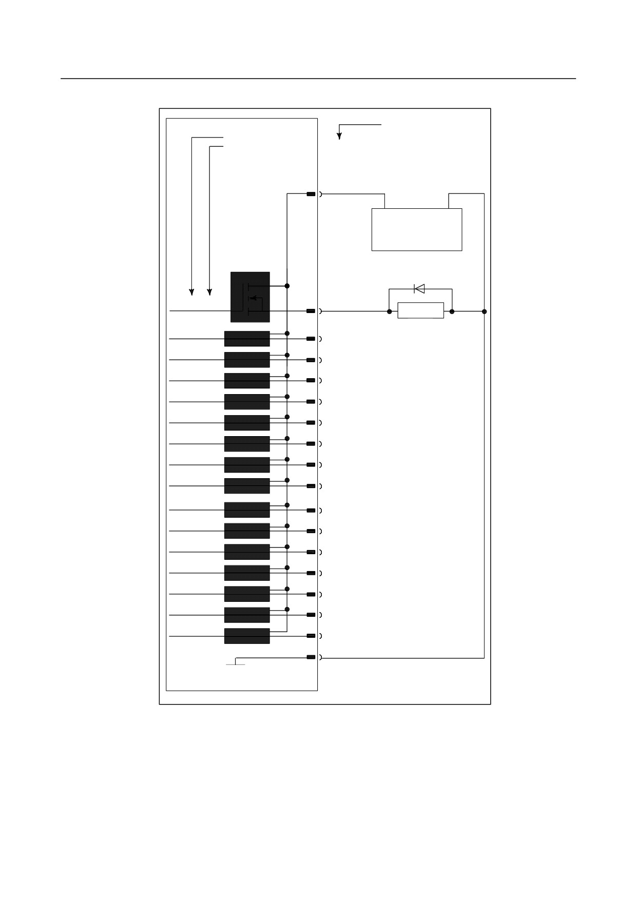
For example, connecting DO
Termina
lNo.
ƒAƒhƒŒƒX”Ô.†
ƒrƒbƒ.
g”Ô
†
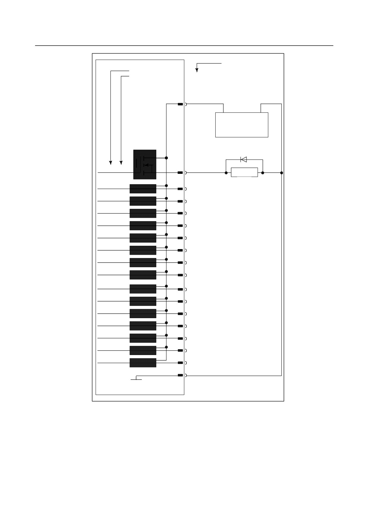
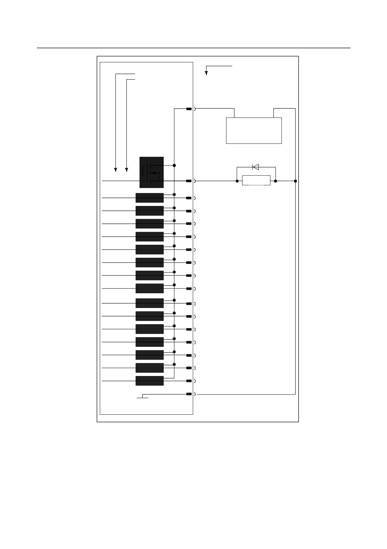
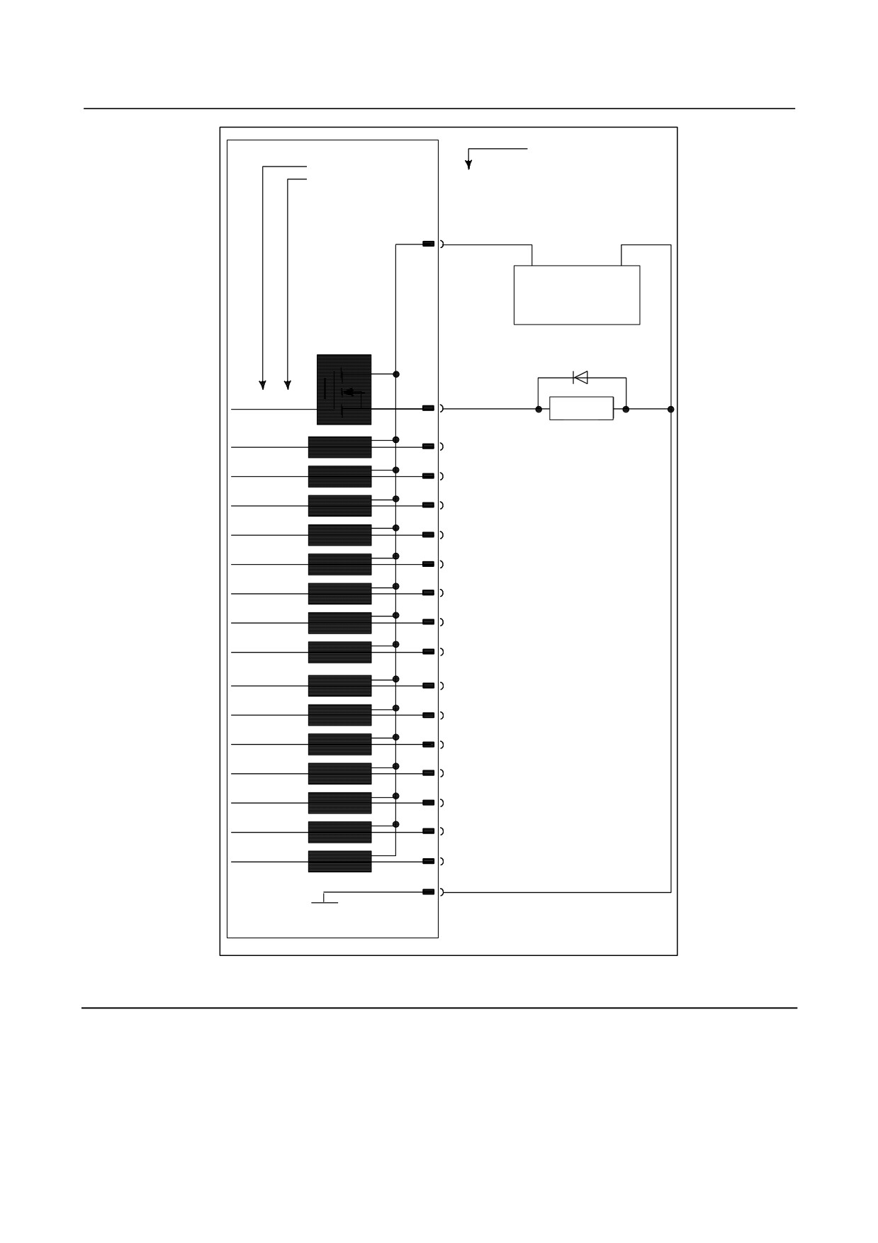
CB104(A24,B24,A25,B25)
CB105(A24,B24,A25,B25)
CB106(A24,B24,A25,B25)
CB107(A24,B24,A25,B25)
DOCOM
+24V
0V
+24V stabilized
+24VˆÀ’艻“dŒ¹
power supply
DV
Yn+0.0
CB104(A16)
ƒŠlay
ƒŒ [
Yn+0.1
CB104(B16)
DV
Yn+0.2
CB104(A17)
DV
Yn+0.3
CB104(B17)
DV
Yn+0.4
CB104(A18)
DV
Yn+0.5
CB104(B18)
DV
Yn+0.6
CB104(A19)
DV
Yn+0.7
CB104(B19)
DV
Yn+1.0
CB104(A20)
DV
Yn+1.1
CB104(B20)
DV
Yn+1.2
CB104(A21)
DV
Yn+1.3
CB104(B21)
DV
Yn+1.4
CB104(A22)
DV
Yn+1.5
CB104(B22)
DV
Yn+1.6
CB104(A23)
DV
Yn+1.7
CB104(B23)
DV
CB104(A01)
0V
- 218 -
B-64303EN/03
9.CONNECTION OF I/O Link SLAVE DEVICES
Terminal
No.
†
Address No.
ƒAƒhƒŒƒX”Ô †
Bit No.”Ô
†
CB104(A24,B24,A25,B25)
CB105(A24,B24,A25,B25)
CB106(A24,B24,A25,B25)
CB107(A24,B24,A25,B25)
DOCOM
+24V
0V
+24V stabilized
+24VˆÀ’艻“dŒ¹
power supply
DV
Yn+2.0
CB105(A16)
Relay
ƒŒ [
Yn+2.1
CB105(B16)
DV
Yn+2.2
CB105(A17)
DV
Yn+2.3
CB105(B17)
DV
Yn+2.4
CB105(A18)
DV
Yn+2.5
CB105(B18)
DV
Yn+2.6
CB105(A19)
DV
Yn+2.7
CB105(B19)
DV
Yn+3.0
CB105(A20)
DV
Yn+3.1
CB105(B20)
DV
Yn+3.2
CB105(A21)
DV
Yn+3.3
CB105(B21)
DV
Yn+3.4
CB105(A22)
DV
Yn+3.5
CB105(B22)
DV
Yn+3.6
CB105(A23)
DV
Yn+3.7
CB105(B23)
DV
CB105(A01)
0V
- 219 -
9.CONNECTION OF I/O Link SLAVE DEVICES
B-64303EN/03
Terminal†
No.
ƒAƒhƒŒƒX”Ôo.†
Bit No.”Ô
†
CB104(A24,B24,A25,B25)
CB105(A24,B24,A25,B25)
CB106(A24,B24,A25,B25)
CB107(A24,B24,A25,B25)
DOCOM
+24V
0V
+24V stabilized
+24VˆÀ’艻“dŒ¹
power supply
DV
Yn+4.0
CB106(A16)
Relay
ƒŒ [
Yn+4.1
CB106(B16)
DV
Yn+4.2
CB106(A17)
DV
Yn+4.3
CB106(B17)
DV
Yn+4.4
CB106(A18)
DV
Yn+4.5
CB106(B18)
DV
Yn+4.6
CB106(A19)
DV
Yn+4.7
CB106(B19)
DV
Yn+5.0
CB106(A20)
DV
Yn+5.1
CB106(B20)
DV
Yn+5.2
CB106(A21)
DV
Yn+5.3
CB106(B21)
DV
Yn+5.4
CB106(A22)
DV
Yn+5.5
CB106(B22)
DV
Yn+5.6
CB106(A23)
DV
Yn+5.7
CB106(B23)
DV
CB106(A01)
0V
- 220 -
B-64303EN/03
9.CONNECTION OF I/O Link SLAVE DEVICES
Terminal†
No.
ƒAƒhƒŒƒX”Ô.†
Bit No.”Ô
†
CB104(A24,B24,A25,B25)
CB105(A24,B24,A25,B25)
CB106(A24,B24,A25,B25)
CB107(A24,B24,A25,B25)
DOCOM
+24V
0V
+24V stabilized
+24VˆÀ’艻“dŒ¹
power supply
DV
CB107(A16)
Yn+6.0
Relay
ƒŒ [
Yn+6.1
CB107(B16)
DV
Yn+6.2
CB107(A17)
DV
Yn+6.3
CB107(B17)
DV
Yn+6.4
CB107(A18)
DV
Yn+6.5
CB107(B18)
DV
Yn+6.6
CB107(A19)
DV
Yn+6.7
CB107(B19)
DV
Yn+7.0
CB107(A20)
DV
Yn+7.1
CB107(B20)
DV
Yn+7.2
CB107(A21)
DV
Yn+7.3
CB107(B21)
DV
Yn+7.4
CB107(A22)
DV
Yn+7.5
CB107(B22)
DV
Yn+7.6
CB107(A23)
DV
Yn+7.7
CB107(B23)
DV
CB107(A01)
0V
9.6.6
I/O Signal Requirements and External Power Supply for DO
Requirements for DI signals
Contact capacity :
30 VDC 16 mA or more
Leakage current between contact points for an open circuit :
1 mA or less (at 26.4 V)
Voltage drop between contact points for a closed circuit :
2 V or less (including the voltage drop in the cables)
- 221 -
9.CONNECTION OF I/O Link SLAVE DEVICES
B-64303EN/03
Ratings for the DO output driver
Maximum load current when turned on :
200 mA or less, including momentary surges
(The maximum current for one DOCOM (power supply) pin must be 0.7 A or less.)
Saturation voltage when turned on :
1.0 V max when the load current is 200 mA
Dielectric strength :
24 V +20% or less, including momentary surges
Leakage current when turned off :
100 μA or less
External power supply for DO
Power supply voltage :
24V±10%
Power supply current :
(Sum of maximum load current including momentary surges + 100 mA) or more
Power-on sequence :
Turn on the external power supply at the same time or before turning on the control unit.
Power-off sequence :
Turn off the external power supply at the same time or after turning off the control unit.
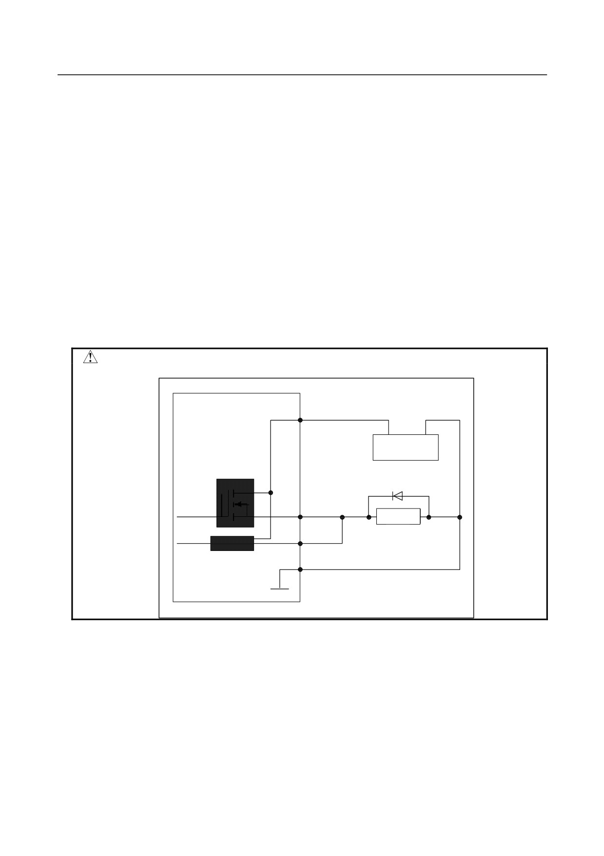
CAUTION
1 Never use the following DO parallel connection.
DOCOM
+24V
0V
DV
Relay
ƒŒ [
DV
0V
- 222 -
B-64303EN/03
9.CONNECTION OF I/O Link SLAVE DEVICES
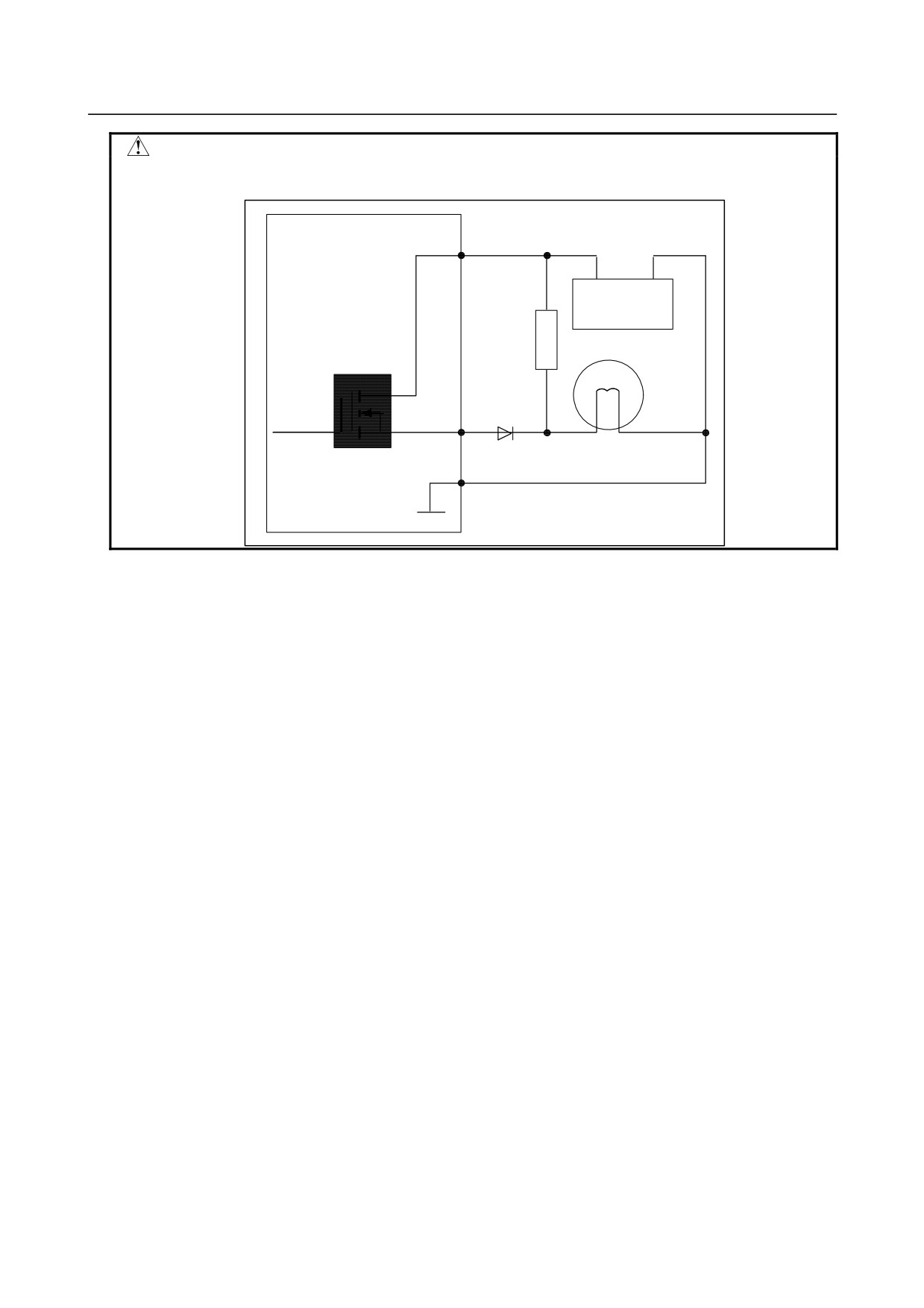
CAUTION
2 When using a dark lighting resistor as shown in the following figure, use a
leakage-proof diode.
DOCOM
+24V
0V
Dark
lighting
ˆÃ“_“”’ï
resister
R
DV
Lampƒv
Leakage-proof diodeƒI [
ƒh
0V
- 223 -

9.CONNECTION OF I/O Link SLAVE DEVICES
B-64303EN/03
NOTE
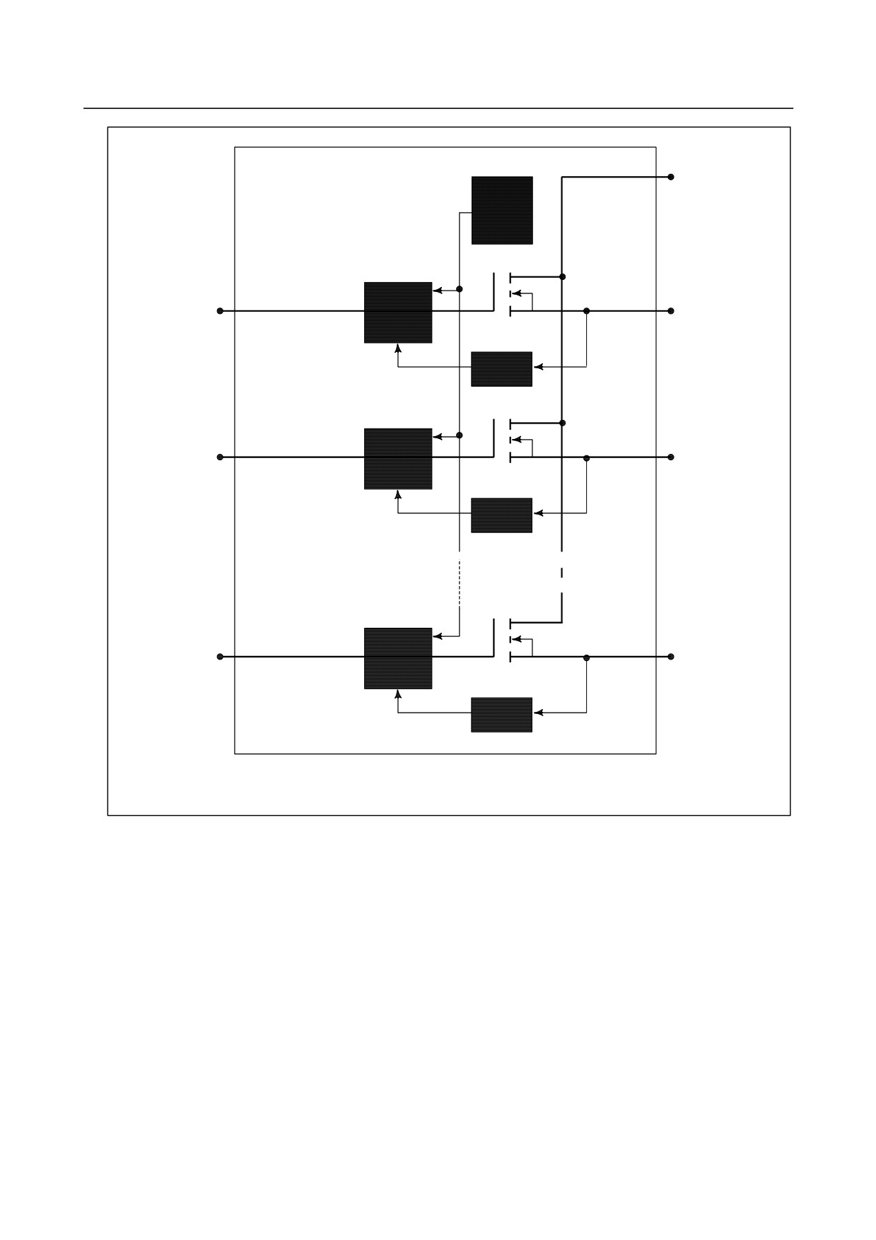
Output signal driver
Each of the output signal driver devices used on this I/O board outputs eight
signals.
A driver device monitors the current of each output signal. If it detects an
overcurrent on an output, it turns off the output. Once an overcurrent causes
an output to turn off, the overcurrent is no longer present. Then, the output is
turned on again. In ground-fault or overload conditions, outputs may turn on
and off alternately. This phenomenon also occurs when a load with a high
surge current is connected.
Each driver device contains an overheat detector circuit. If an overcurrent is
observed on an output continuously because of a ground-fault or similar reason
and the temperature in the device rises, the overheat detector circuit turns off all
eight outputs. The output-off state is maintained. This state can be released
by logically turning off then on again the outputs after the internal temperature of
the device drops to a specified level. This state can also be released by turning
off the system power supply.
The output signals of the driver devices are assigned the following addresses:
Device #0: Yn+0.0 to Yn+0.7
Device #1: Yn+1.0 to Yn+1.7
Device #2: Yn+2.0 to Yn+2.7
Device #3: Yn+3.0 to Yn+3.7
Device #4: Yn+4.0 to Yn+4.7
Device #5: Yn+5.0 to Yn+5.7
Device #6: Yn+6.0 to Yn+6.7
Device #7: Yn+7.0 to Yn+7.7
If NC diagnosis shows that an output is on but the output is actually not turned
on, an overload on that output or another output in the same device may have
turned off the eight outputs of that device. In such a case, turn off the system
power supply and remove the cause of the overload.
- 224 -
B-64303EN/03
9.CONNECTION OF I/O Link SLAVE DEVICES
DOCOM
OHD
CONTROL
IN#0
OUT#0
LOGIC
OCD
CONTROL
IN#1
OUT#1
LOGIC
OCD
E
E
E
E
・
E
・E
・E
・
E
・
E
・
・
・
E
・
・
CONTROL
IN#7
OUT#7
LOGIC
OCD
HD: Over-heat de
ector circuit, OCD: Over-current detector circuit
- 225 -
9.CONNECTION OF I/O Link SLAVE DEVICES
B-64303EN/03
9.6.7
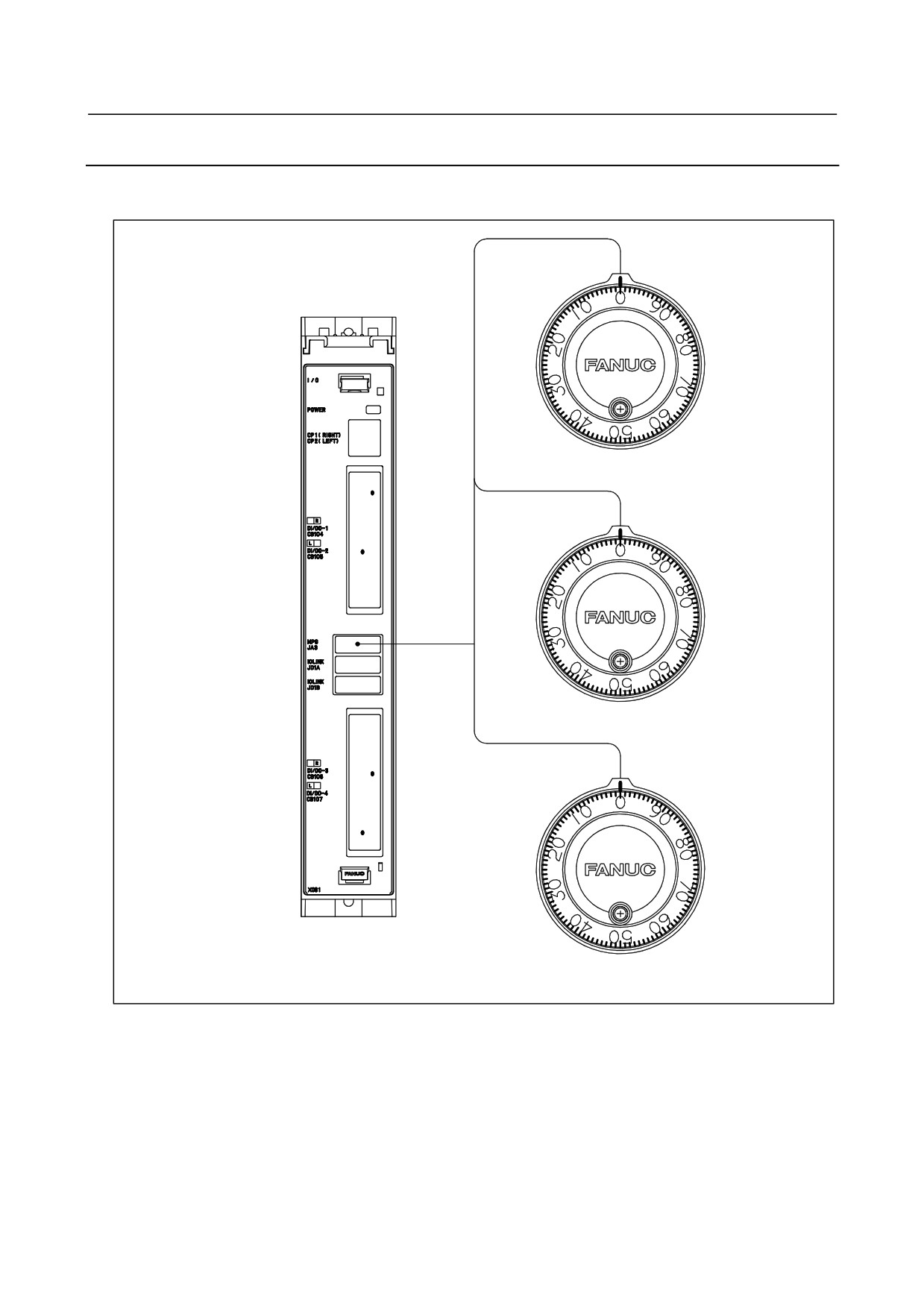
Connecting the Manual Pulse Generator
Manual pulse generators are used to manually move an axis in the handle feed mode.
I/O unit for 0i
Manual Pulse Generator (No.1)
MPG
JA3
Manual Pulse Generator (No.2)
Manual Pulse Generator (No.3)
- 226 -