FANUC Series 0i-MODEL D, Series 0i Mate-MODEL D. CONNECTION MANUAL (HARDWARE) - page 7
B-64303EN/03
9.CONNECTION OF I/O Link SLAVE DEVICES
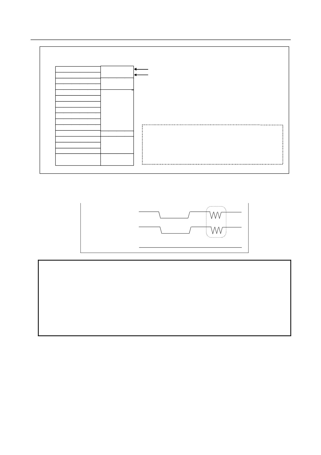
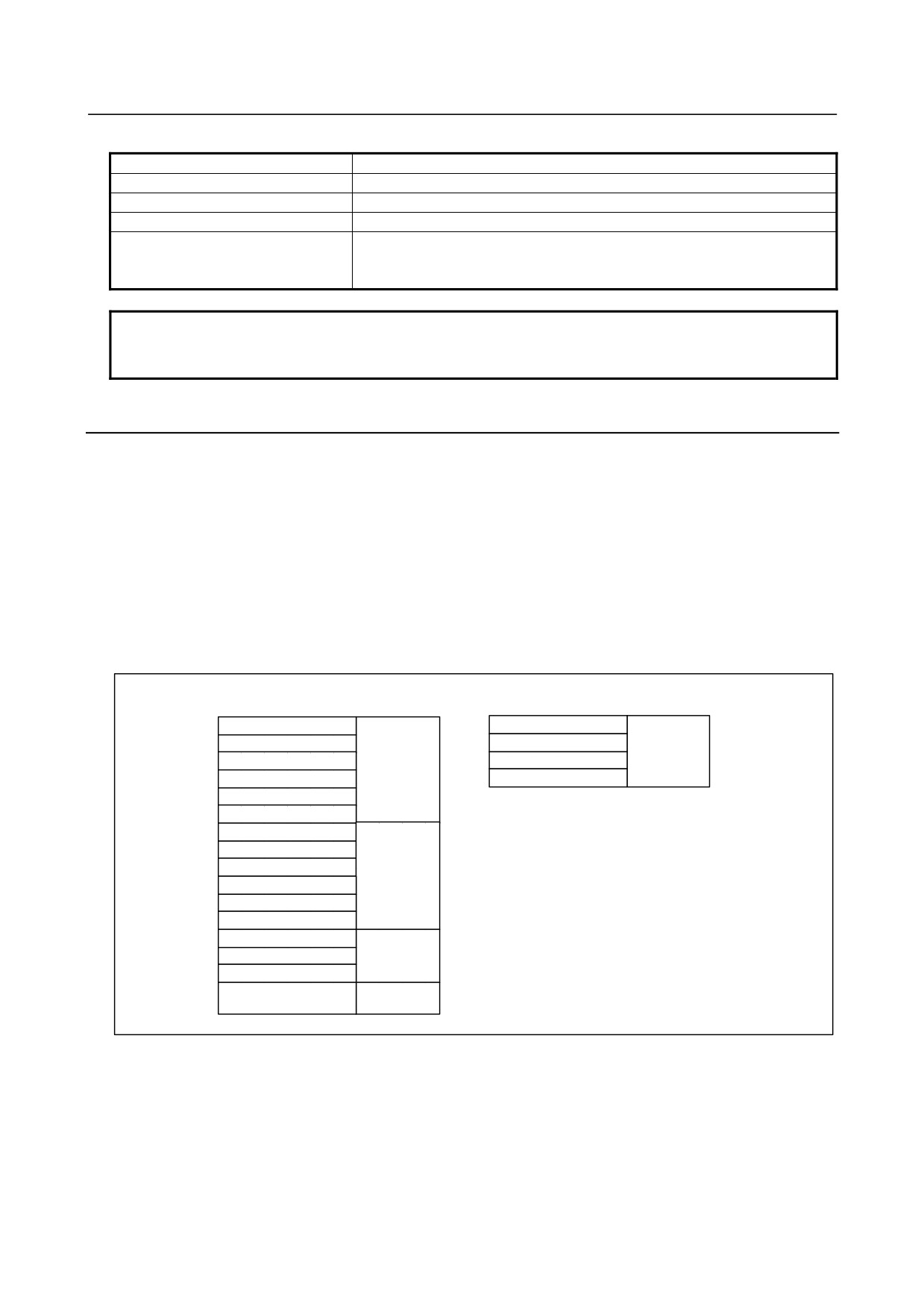
When DI addresses are allocated in units of 16 bytes, starting at X0008
X0008
General-purpose
*ESP fixed signal
X0009
input signal
*DECn fixed signal
X0010
Reserved
X0011
X0012
X0013
X0014
X0015
Matrix input
signal
X0016
X0017
X0018
Although fixed signals such as SKIP cannot be used, allocating DI
X0019
Reserved
addresses starting from X0008 allows the *DECn signal to be used
X0020(for 1st MPG)
and the *ESP fixed signal to be allocated to an address for which the
X0021(for 2nd MPG)
common voltage is fixed to 24 V.
MPG
X0022(for 3rd MPG)
(Fixed signals cannot be allocated to the for the matrix input signals.)
X0023(DO alarm
DO alarm
detection)
detection
Turning the DO (output signal) power on and off (DOCOM)
All the DO signals can be turned off simultaneously by turning off (opening) the DO (output signal)
power supply pin "DOCOM". Doing so causes the DO signal status to change as shown below.
ON
DOCOM
OFF
When DO is ON in
ON
the sequence
OFF
When DO is OFF in
ON
the sequence
OFF
NOTE
When the DO signal is in the ON state in the sequence, the ON or OFF state of
the DOCOM pin determines the state of the signal, as indicated by the dotted
lines in the above figure. Do not turn off the +24 V supply, provided by the
CPD1 to the I/O module, during the operation. Turning off the +24 V supply
would cause a CNC communication alarm. When turning on the power, the
+24 V supply to the I/O module must be turned on before or at the same time as
the power supply to the CNC. When turning off the power, the +24 V supply to
the I/O module must be turned off after or at the same time as the power supply
to the CNC.
Parallel DO (output signal) connection
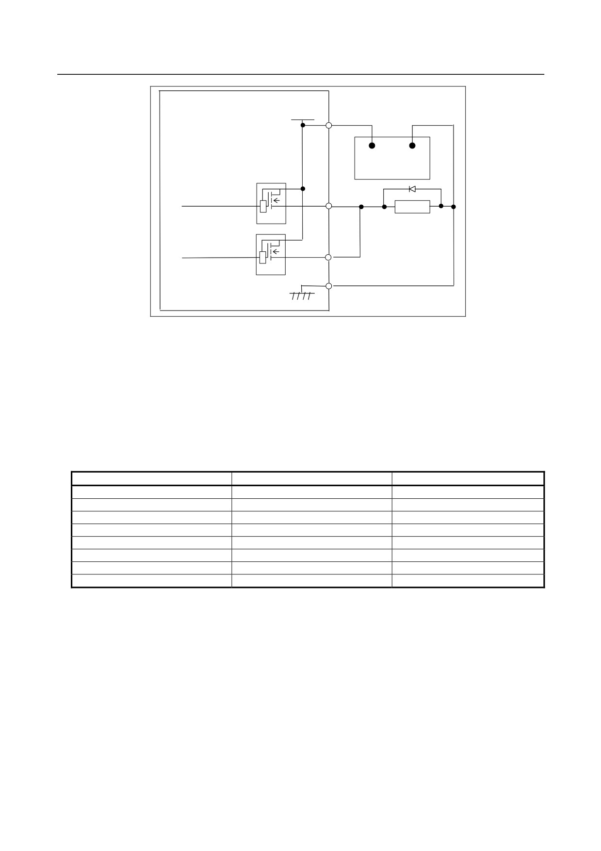
The DO load current can be doubled by connecting two DO points in parallel and turning them on and off
simultaneously in sequence, as shown in the figure below. The maximum load current per DI point is
200 mA. Connecting two DO points in parallel and turning them on at the same time produces a current
of 400 mA. Note that, however, when two DO points are connected in parallel, the leakage current also
doubles while they are off (max. 40 mA).
- 167 -
9.CONNECTION OF I/O Link SLAVE DEVICES
B-64303EN/03
CE53(A25), (B25)
DOCOM
CE54(B24), (A25), (B25)
+24V
0V
+24V stabilized
power supply
Relay
DV
DV
DO (output signal) alarm detection
The DO driver of the I/O module is capable of detecting an overcurrent and measuring its own
temperature. If an accident, such as connecting the cable to ground, causes an abnormal increase in the
load current or in the driver temperature, a protection circuit, which is provided for each DO driver (1
byte), is activated which keeps the DO signal for the relevant 1 byte in the OFF state until the cause of the
problem is eliminated. Even if this occurs, the CNC and the I/O module continue operating. The DI
address (Xm+15) identifies which DO driver has detected an alarm. The following table shows the
correspondence between the DI address (Xm+15) bits and the DO addresses. Bit value "1" indicates that
the corresponding DO driver has detected an alarm. The contents of the Xm+15 area can be checked by
using the DGN screen of the CNC or by performing the alarm processing for the area in advance by using
Ladder. This helps alarm detection and recovery.
Alarm detection address and bit
DO address
Remarks
Xm+15.0
Yn+0
Xm+15.1
Yn+1
Xm+15.2
Yn+2
Xm+15.3
Yn+3
Xm+15.4
Yn+4
Xm+15.5
Yn+5
Xm+15.6
Yn+6
Xm+15.7
Yn+7
Reserved
- 168 -
B-64303EN/03
9.CONNECTION OF I/O Link SLAVE DEVICES
9.4
CONNECTION OF OPERATOR'S PANEL I/O MODULE
AND POWER MAGNETICS CABINET I/O MODULE
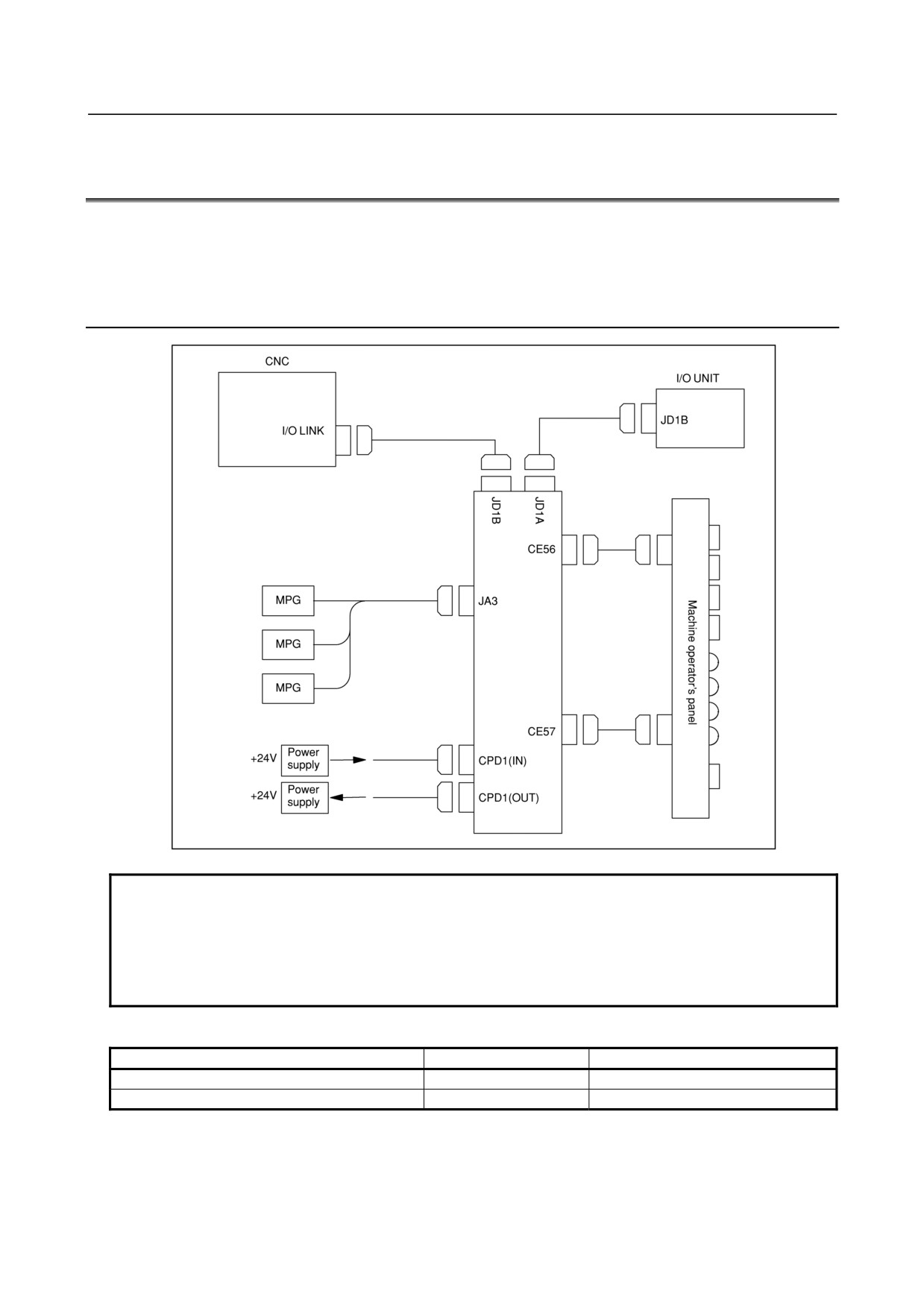
The difference between the operator's panel I/O module and the power magnetics cabinet I/O module lies
in whether an interface to a manual pulse generator is provided. The power magnetics cabinet does not
provide an interface to a manual pulse generator.
9.4.1
Overall Connection Diagram
JD51A
NOTE
When the operator's panel I/O module is used together with a unit (connector
panel I/O module) connected to the I/O Link supporting another MPG interface,
only the MPG interface of the unit (module) closest to the CNC connected to the
I/O Link is enabled. The following screw type connectors cannot be used to
connect the I/O Link or MPG.
Connectors that cannot be used on the cable side
Specification
Manufacturer
Connector case
FI-20-CV7
Hirose Electric Co., Ltd.
Connector case and connector
FI30-20S-CV7
Hirose Electric Co., Ltd.
- 169 -
9.CONNECTION OF I/O Link SLAVE DEVICES
B-64303EN/03
9.4.2
Power Connection
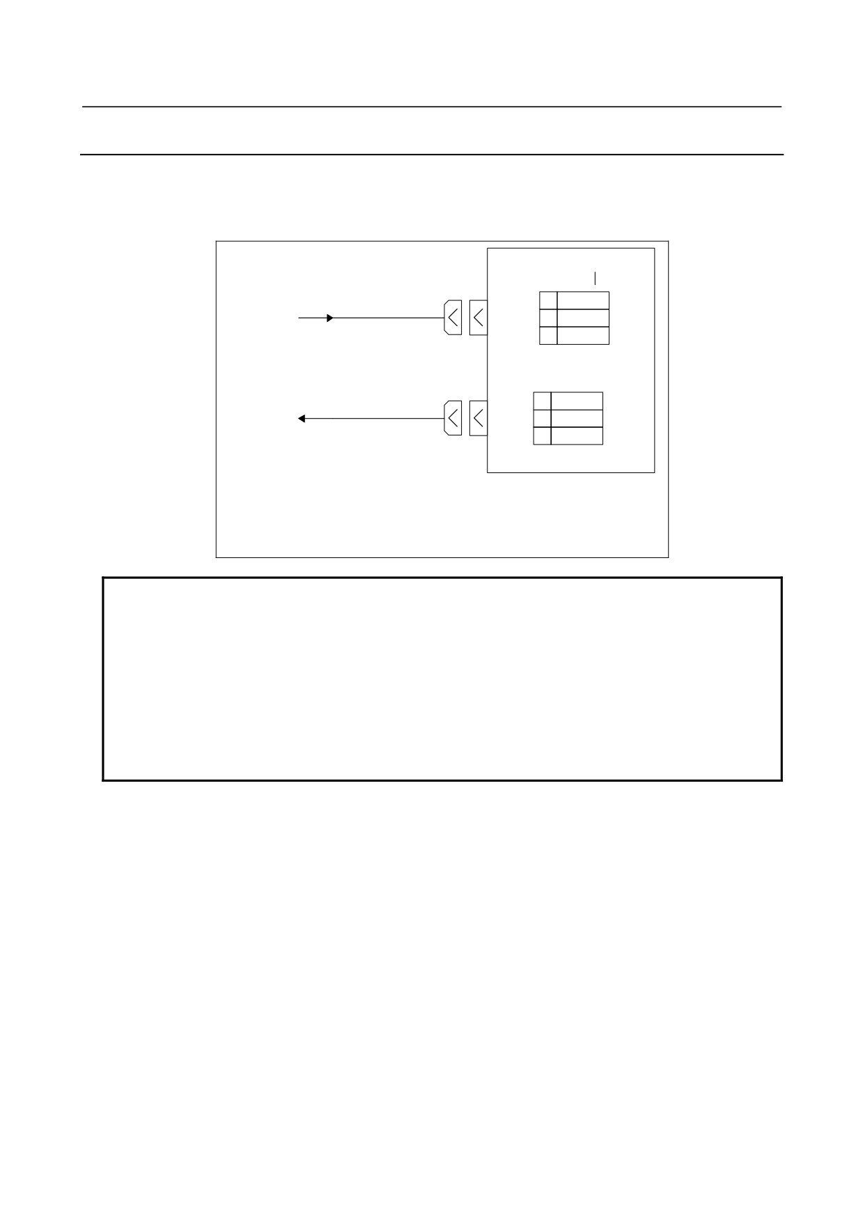
Provide the CPD1 (IN) connector, shown below, with the power necessary for the printed circuit board
operation and that for DI operation. To facilitate power division, the power is output to CPD1 (OUT)
exactly as it is input from CPD1 (IN). When power division is required, use CPD1 (OUT).
Up to 1.0 A can be supplied by branching.
CPD1(IN)
DOCOM
01
+24V
24 V power
02
0V
supply
03
CPD1(OUT)
01
+24V
24 V power
02
0V
supply
03
Recommended cable-side connector:
A02B-0120-K324 (including the following connector housing and case)
(Housing: Japan AMP 1-178288-3)
(Contacts: Japan AMP
1-175218-5)
NOTE
The specification of the power supply connector CPD1 (IN) is the same as that
for CPD1 (OUT). There are no indications on the printed circuit board to
distinguish between the IN and OUT connectors. Do not turn off the +24 V
supply to the connector during operation. Turning off the +24 V supply will
cause a CNC communication alarm. When turning on the power, the +24 V
supply to the I/O module must be turned on before or at the same time as the
power supply to the CNC. When turning off the power, the +24 V supply to the
I/O module must be turned off after or at the same time as the power supply to
the CNC.
- 170 -
B-64303EN/03
9.CONNECTION OF I/O Link SLAVE DEVICES
9.4.3
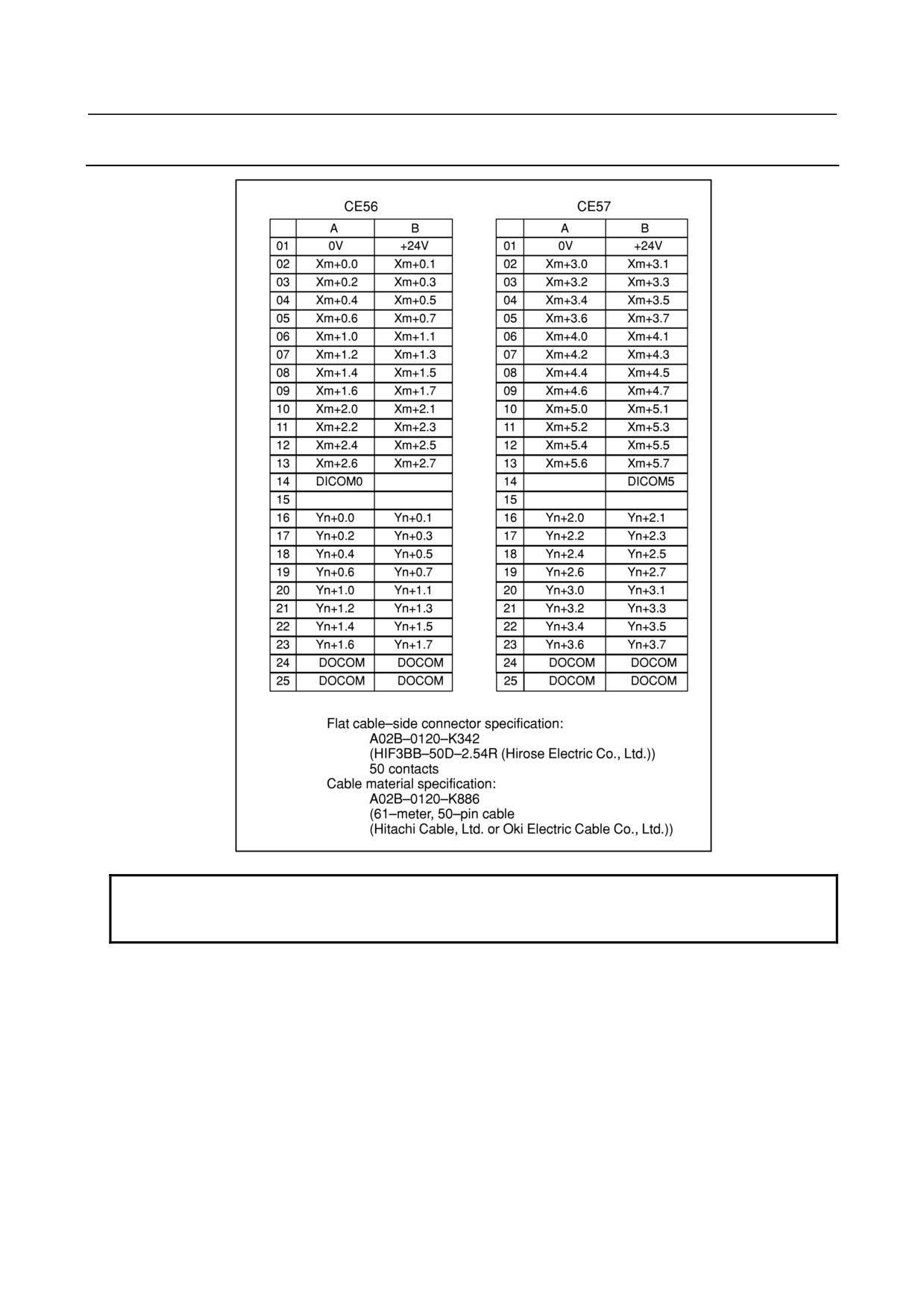
DI/DO Connector Pin Arrangement
NOTE
An output DC voltage of +24 V at CE56 (B01) and CE57 (B01) is for DI signals.
Do not supply 24 VDC to these pins from the outside.
- 171 -
9.CONNECTION OF I/O Link SLAVE DEVICES
B-64303EN/03
9.4.4
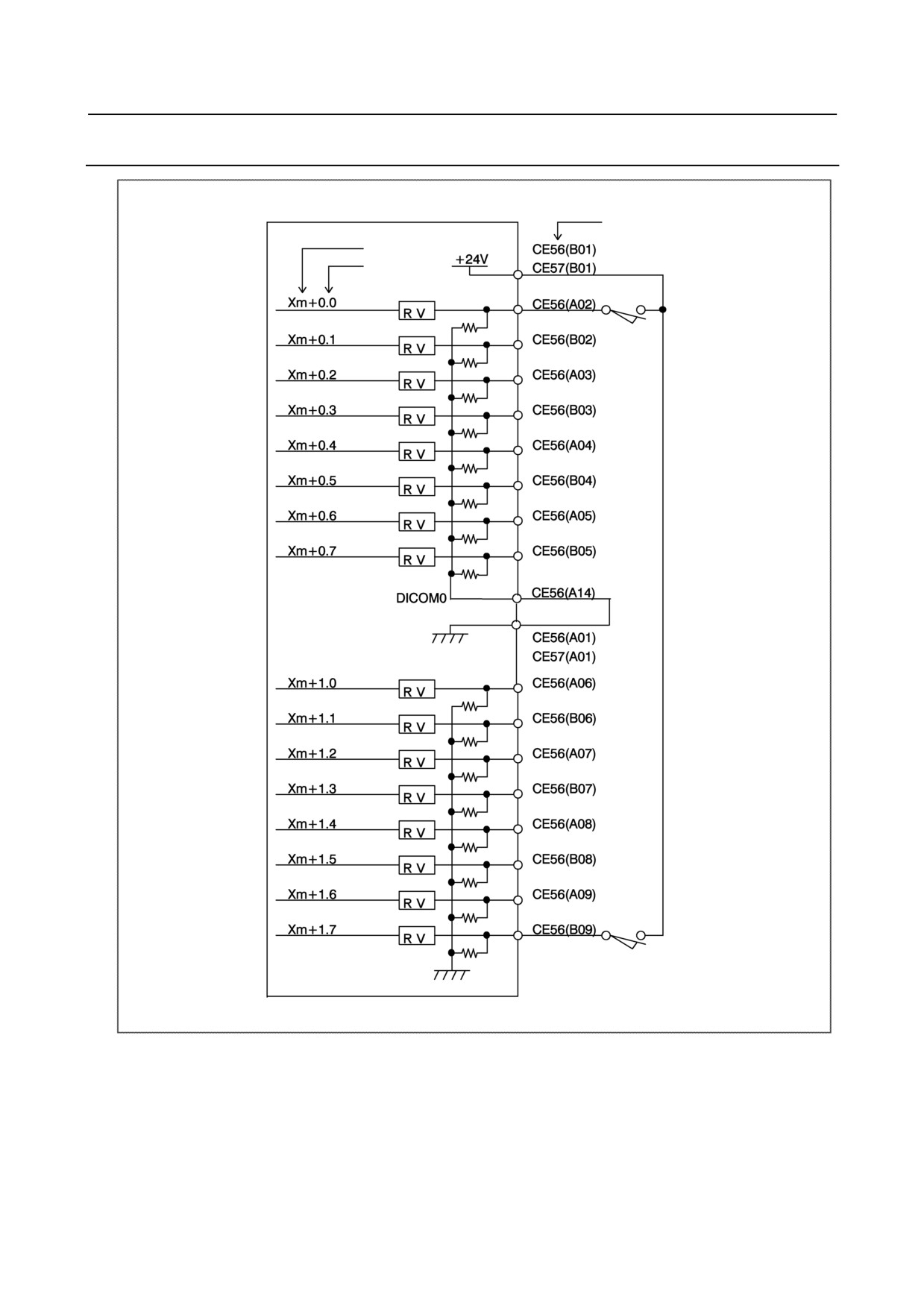
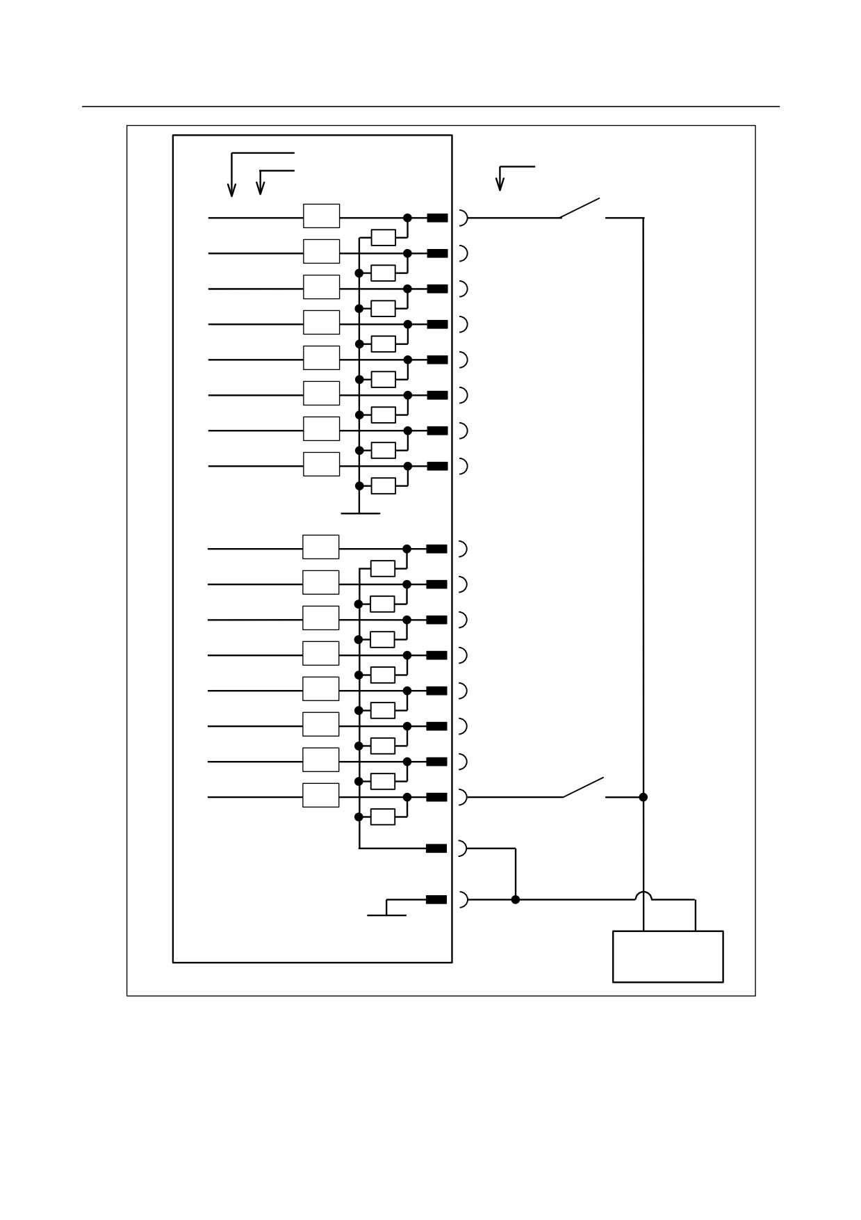
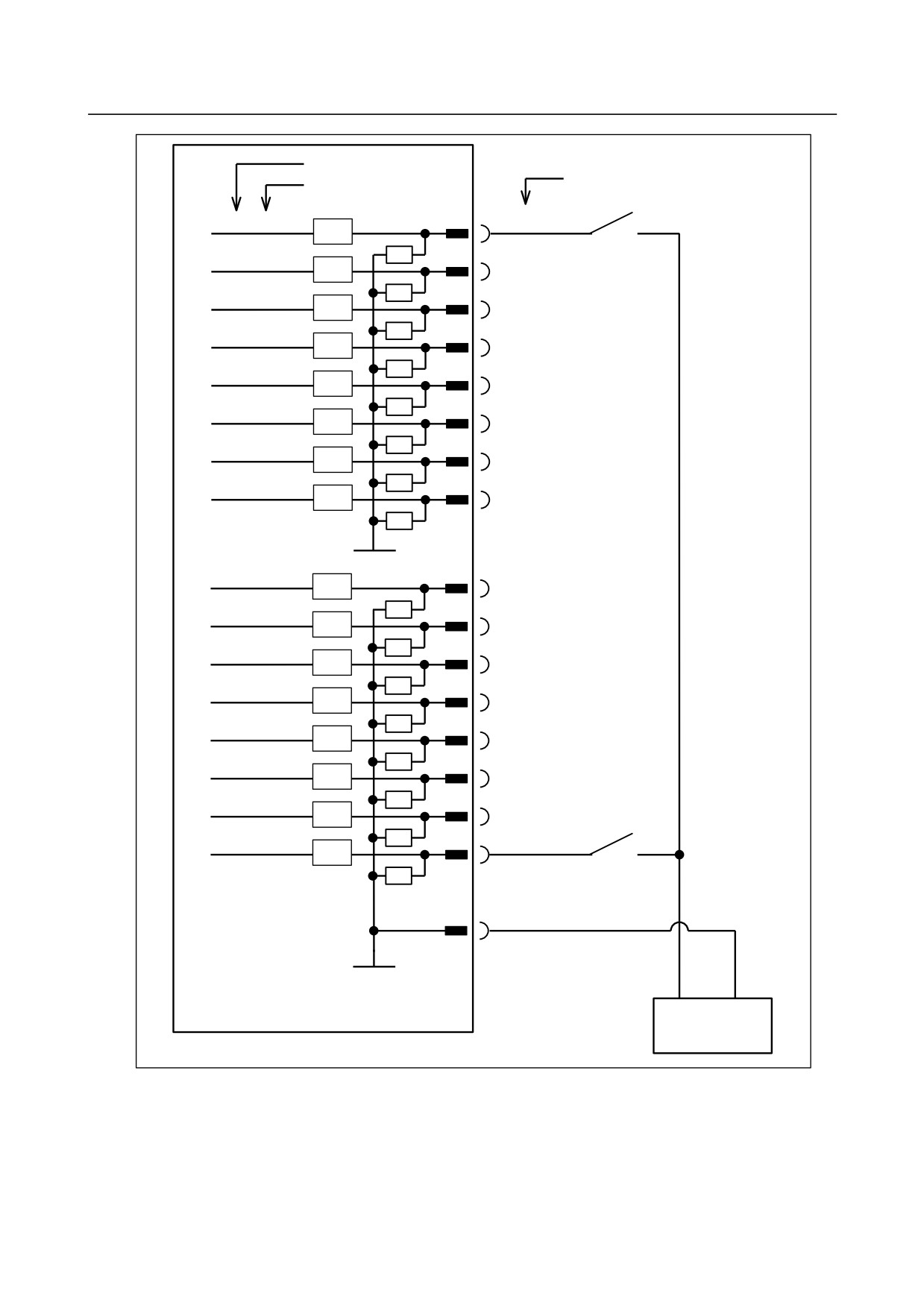
DI (General-purpose Input Signal) Connection
Pin No.
Address No.
Bit No.
- 172 -
B-64303EN/03
9.CONNECTION OF I/O Link SLAVE DEVICES
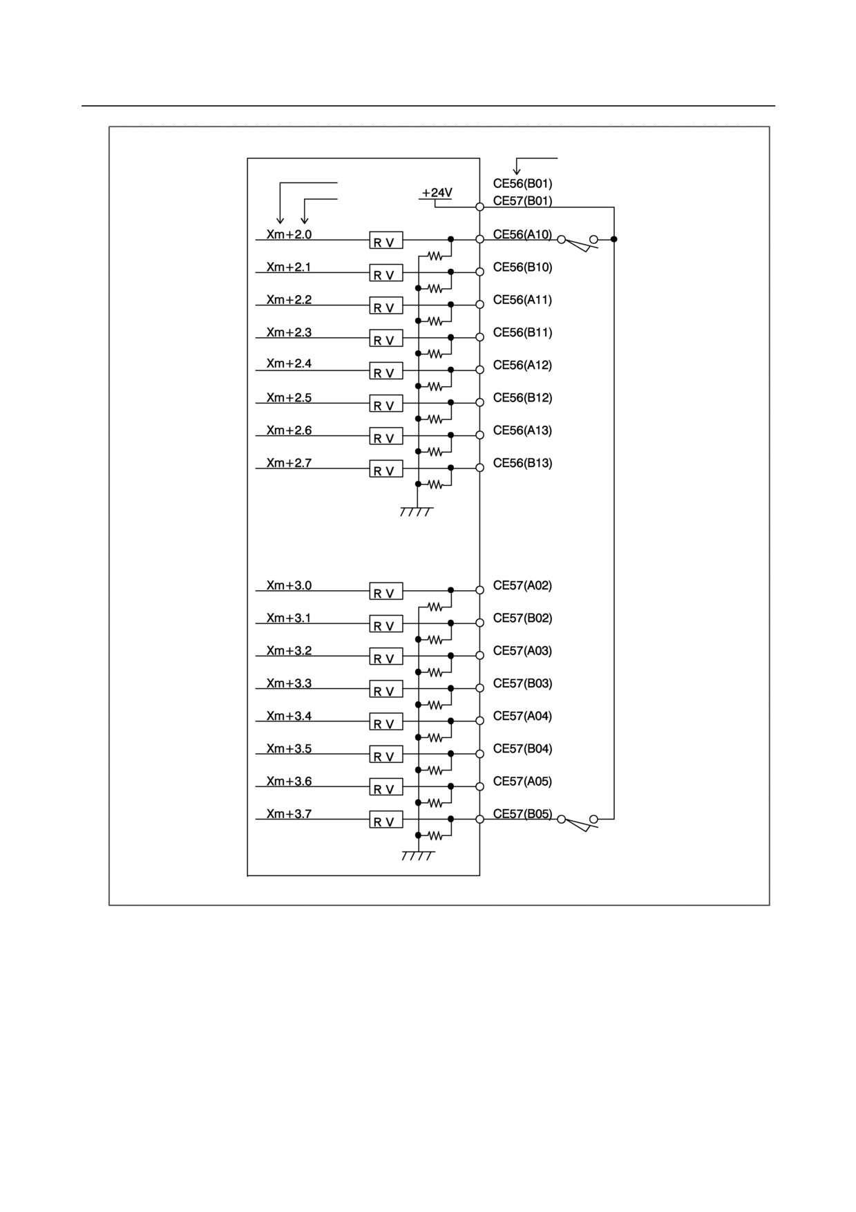
Pin No.
Address No.
Bit No.
- 173 -
9.CONNECTION OF I/O Link SLAVE DEVICES
B-64303EN/03
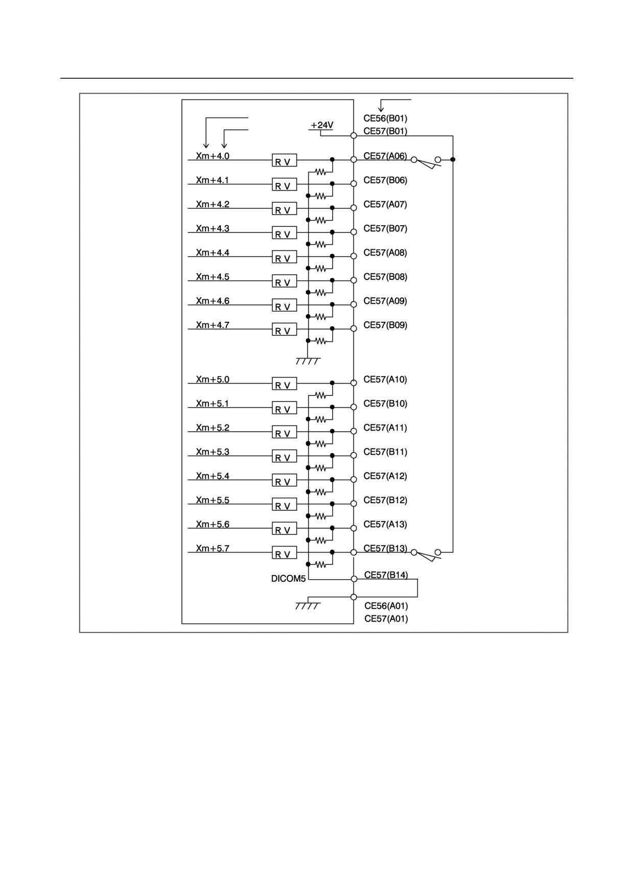
Pin No.
Address No.
Bit No.
- 174 -

B-64303EN/03
9.CONNECTION OF I/O Link SLAVE DEVICES
NOTE
1 Xm+0.0 through Xm+0.7 and Xm+5.0 through Xm+5.7 are DI pins for which a
common voltage can be selected. That is, by connecting the DICOM0
CE56(A14) or DICOM5 CE57(B14) pin to the +24 V power supply, a DI signal
can be input with its logical state reversed. If, however, a cable is connected to
ground, it has the same effect as inputting an ON state DI signal. To prevent
this from occurring, the connection of the DICOM0 CE56(A14) and DICOM5
CE57(B14) pins to the 0 V power supply is recommended whereever possible.
For safety reasons, the emergency stop signal needs to be allocated to an
appropriate bit of the addresses for which the common voltage is fixed. See
"Address allocation" in Section 9.6.9 for details of how to allocate the emergency
stop signal.
For unused DI pins allocated to the addresses for which the common voltage is
fixed, the logic is fixed to "0". For unused pins allocated to the addresses for
which the common voltage can be selected, the logic is fixed to "0" when the
DICOM0 CE56(A14) or DICOM5 CE57(B14) pin is connected to the 0 V power
supply. When the DICOM0 CE56(A14) or DICOM5 CE57(B14) pin is
connected to the +24 V power supply, the logic is fixed to "1". The logic of the
unused pins is variable when the contacts of the DICOM0 CE56(A14) and
DICOM5 CE57(B14) pins are open.
2 An output DC voltage of +24 V at CE56 (B01) and CE57 (B01) is for DI signals.
Do not supply 24 VDC to these pins from the outside.
- 175 -
9.CONNECTION OF I/O Link SLAVE DEVICES
B-64303EN/03
9.4.5
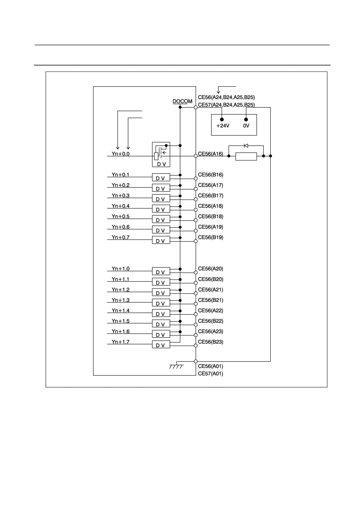
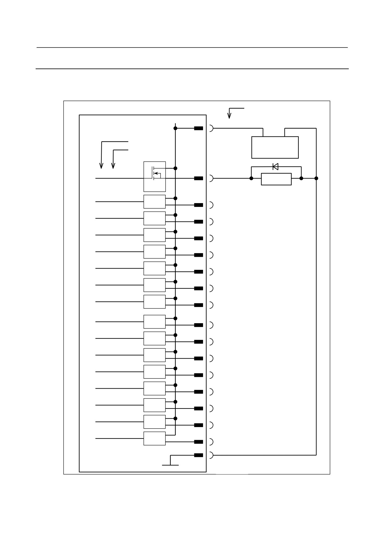
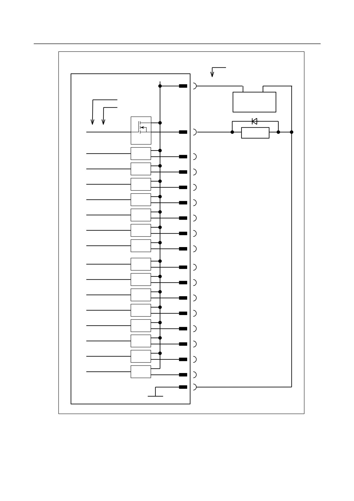
DO (Output Signal) Connection
Pin No.
Address No.
Bit No.
+24V stabilized power supply
Relay
- 176 -
B-64303EN/03
9.CONNECTION OF I/O Link SLAVE DEVICES
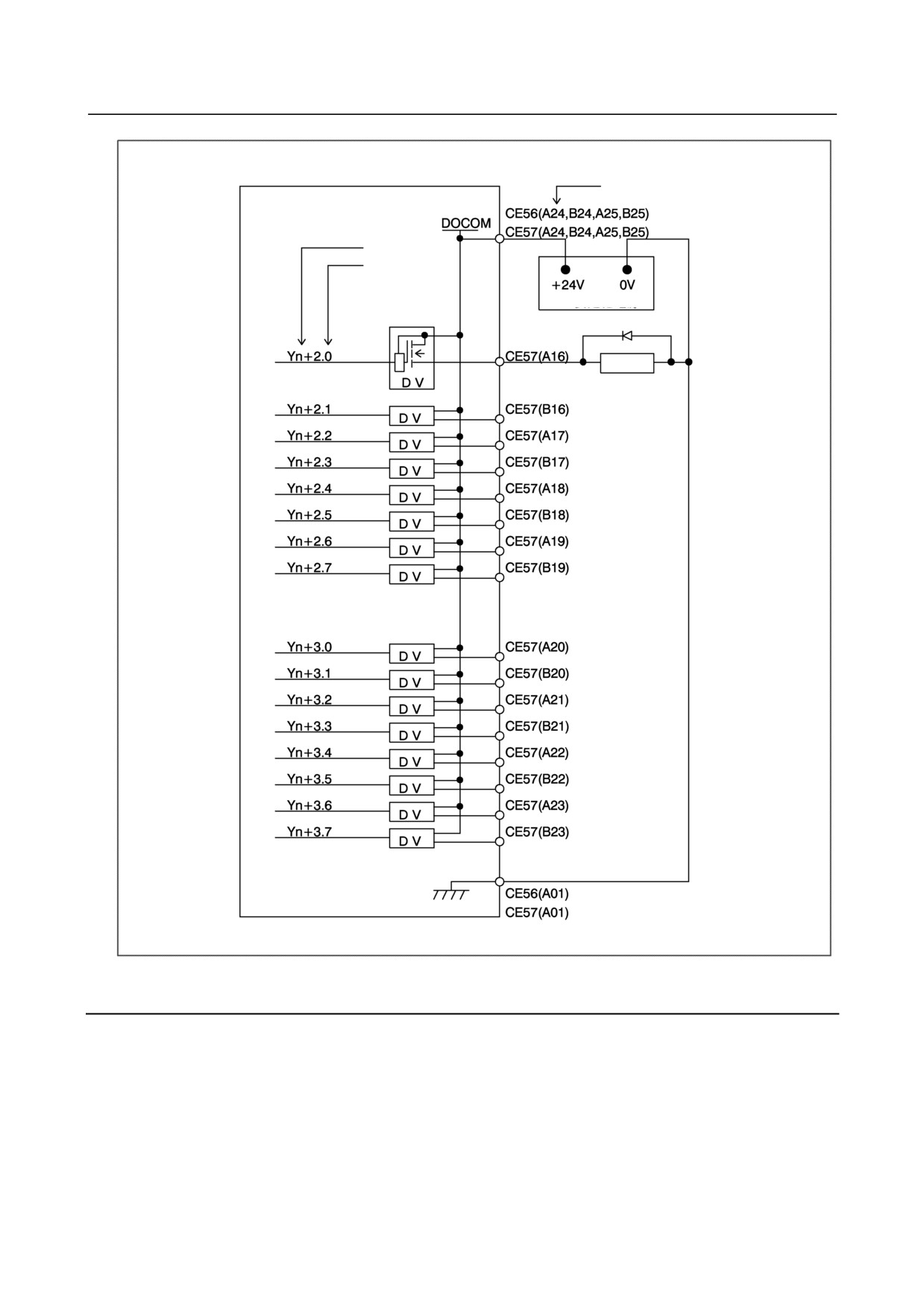
Pin No.
Address No.
Bit No.
+24V stabilized power supply
Relay
9.4.6
Manual Pulse Generator Connection
For details of the connection of the manual pulse generator, see Section 9.2.15.
- 177 -
9.CONNECTION OF I/O Link SLAVE DEVICES
B-64303EN/03
9.4.7
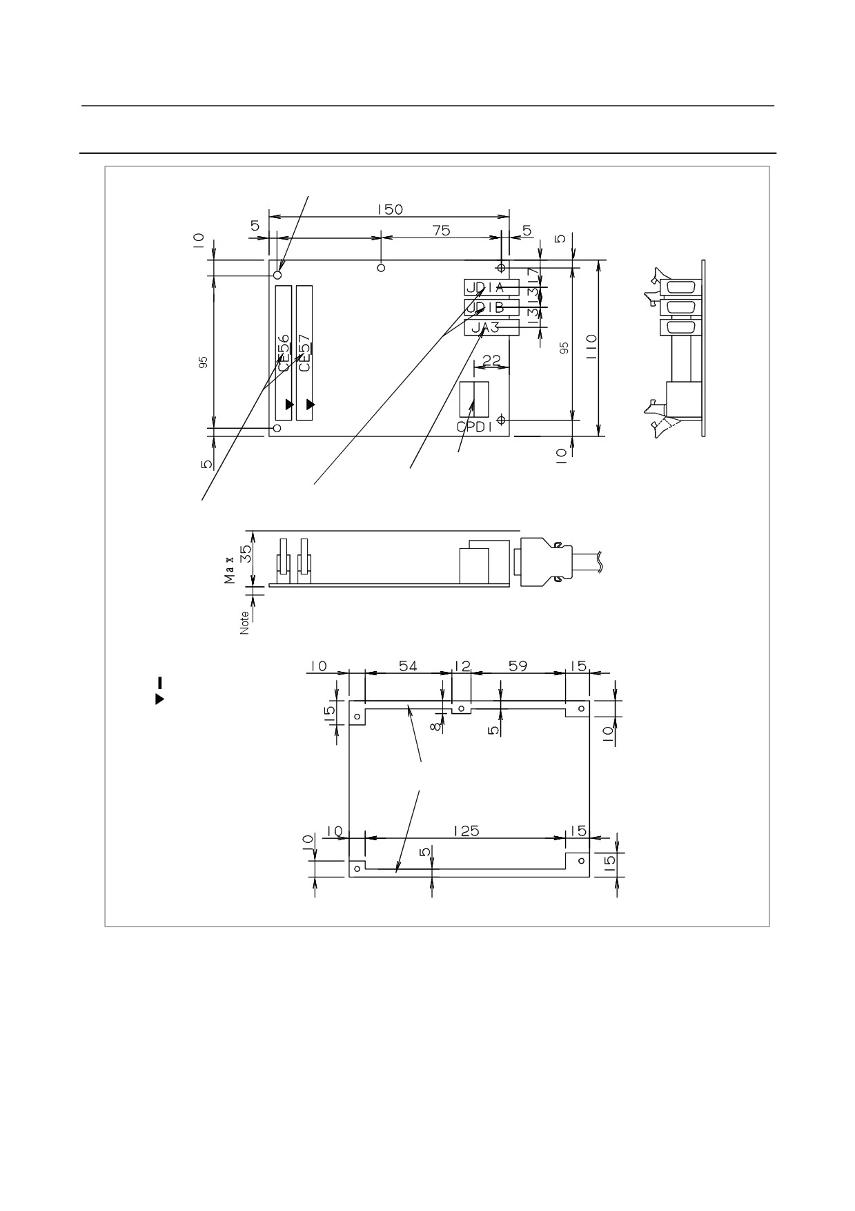
External View
5-φ3.2
65
24 V power supply
connection
Manual pulse generator connection
I/O Link signal connection
Operator's panel DI/DO interface
24 V power supply
Note) Lead wires and other components are mounted on the rear face of the
printed circuit board. Ensure that the printed circuit boards are
spaced 5 mm or more from one another to prevent interference.
: Polarity guide
: A1 pin mark
Available area to install plate at the rear side
(Perspective drawing viewed from the front)
- 178 -
B-64303EN/03
9.CONNECTION OF I/O Link SLAVE DEVICES
9.4.8
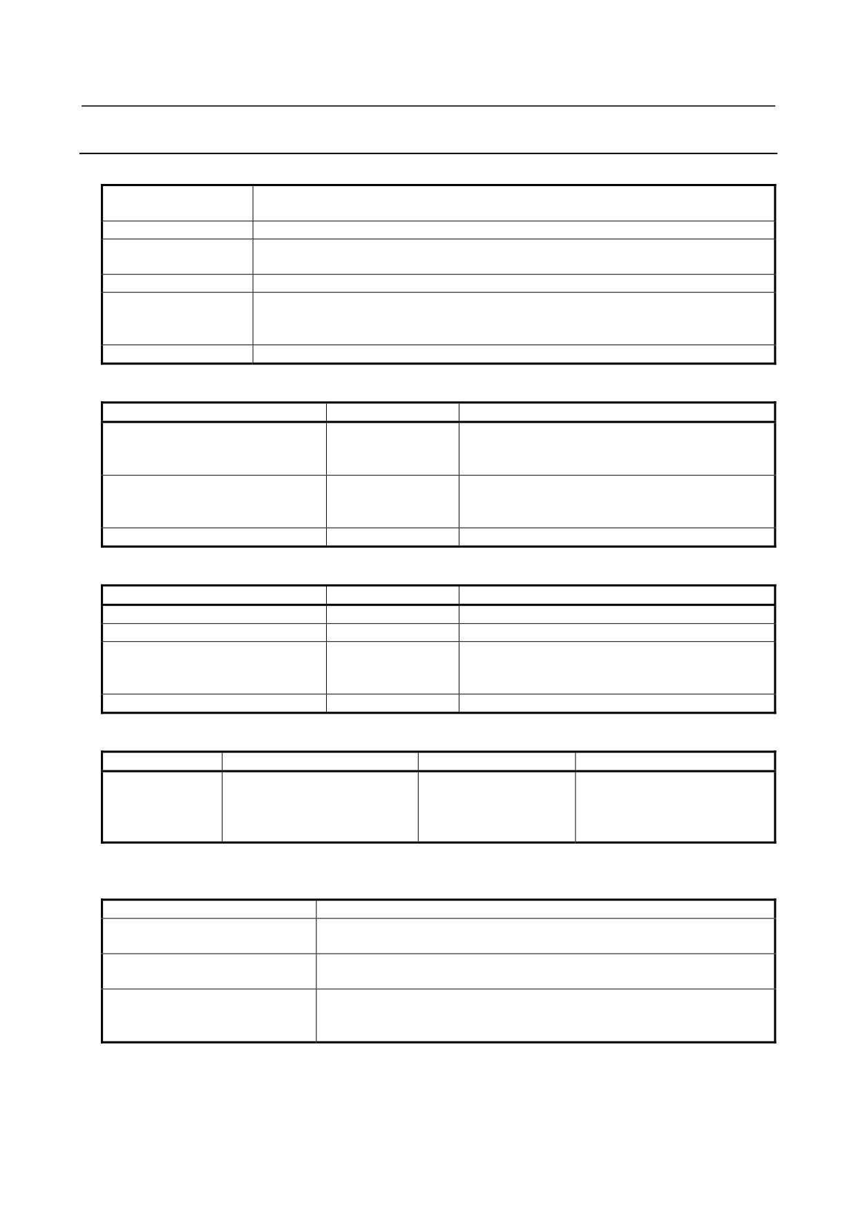
Specifications
Installation specifications
During operation
0°C to 58°C
Ambient temperature
During storage and transportation
-20C to 60°C
Temperature change
Max. 1.1°C/min.
Normal
75% or less
Relative humidity
Short term (1 month or less)
95% or less
Vibration
During operation
0.5 G or less
Ordinary machining factory environment (Special consideration is required when installing
Environment
the module in a dusty place or where highly concentrated cutting lubricant or organic
solvent is used.)
Other requirements
(1) Install the I/O module in a fully enclosed cabinet.
Ordering specifications
Item
Specification
Remarks
Operator's panel I/O module
A20B-2002-0520
DI : 48 points
(with MPG interface)
DO : 32 points
MPG interface is supported.
Power magnetics panel I/O module
A20B-2002-0521
DI : 48 points
(without MPG interface)
DO : 32 points
MPG interface is not supported.
Fuse (replacement part)
A03B-0815-K001
1A
Module specifications
Item
Specification
Remarks
DI points
48 points
24 V input
DO points
32 points
24 V source type output
CNC interface
FANUC I/O Link
Up to 16 modules can be connected as CNC slaves.
connection
Or, a maximum of 1024 points can be supported on
both the input and output sides.
MPG interface
Max. 3 units
Power supply rating
Module
Supply voltage
Power supply rating
Remarks
Operator's panel
24 VDC ±10% is supplied from
0.3A+7.3mA×DI
DI = number of DI points in the
I/O module and
power supply connector CPD1.
ON state
power magnetics
The tolerance of ±10% includes
cabinet I/O module
momentary and ripple currents.
DI (input signal) specifications
(general-purpose input signal)
Contact rating
30 VDC, 16 mA or more
Open circuit intercontact leakage
1 mA or less (at 26.4 V)
current
Closed circuit intercontact
2 V or less (including cable voltage drop)
voltage drop
Receiver delay: Max. 2 ms
Delay
The time required for I/O Link transmission between the CNC and I/O module
(max. 2 ms + CNC ladder scan cycle) must also be taken into account.
- 179 -
9.CONNECTION OF I/O Link SLAVE DEVICES
B-64303EN/03
DO (output signal) specifications
Maximum load current in ON state
200 mA or less (including momentary current)
Saturation voltage in ON state
Max. 1 V (when load current is 200 mA)
Withstand voltage
24 V +20% or less (including momentary values)
Leakage current in OFF state
20 μA or less
Driver delay: Max. 50 μs
Delay
The time for I/O Link transmission between the CNC and I/O module (max. 2
ms + CNC ladder scan cycle) must also be taken into account.
NOTE
Ensure that the maximum current per DOCOM pin (DO power supply pin) does
not exceed 0.7 A.
9.4.9
Other Notes
DO signal reaction to a system alarm
There is a possibility that the I/O module will not operate normally due to a failure of CNC or I/O Link
slave module, or abnormally power supply voltage. To prevent accidents even in this case, design the
machine to operate safely by making a safety circuit outside the I/O module.
The circuit of this I/O module is designed so that all DO signals are turned off if a system alarm is
occurred in the CNC which controls the I/O module, or if a power of the CNC or the I/O module is turned
off. However, it cannot be guaranteed that DO signals of the I/O module will certainly be turned off.
Therefore, manage signals related to safety by making a safety circuit outside this I/O module.
Address allocation
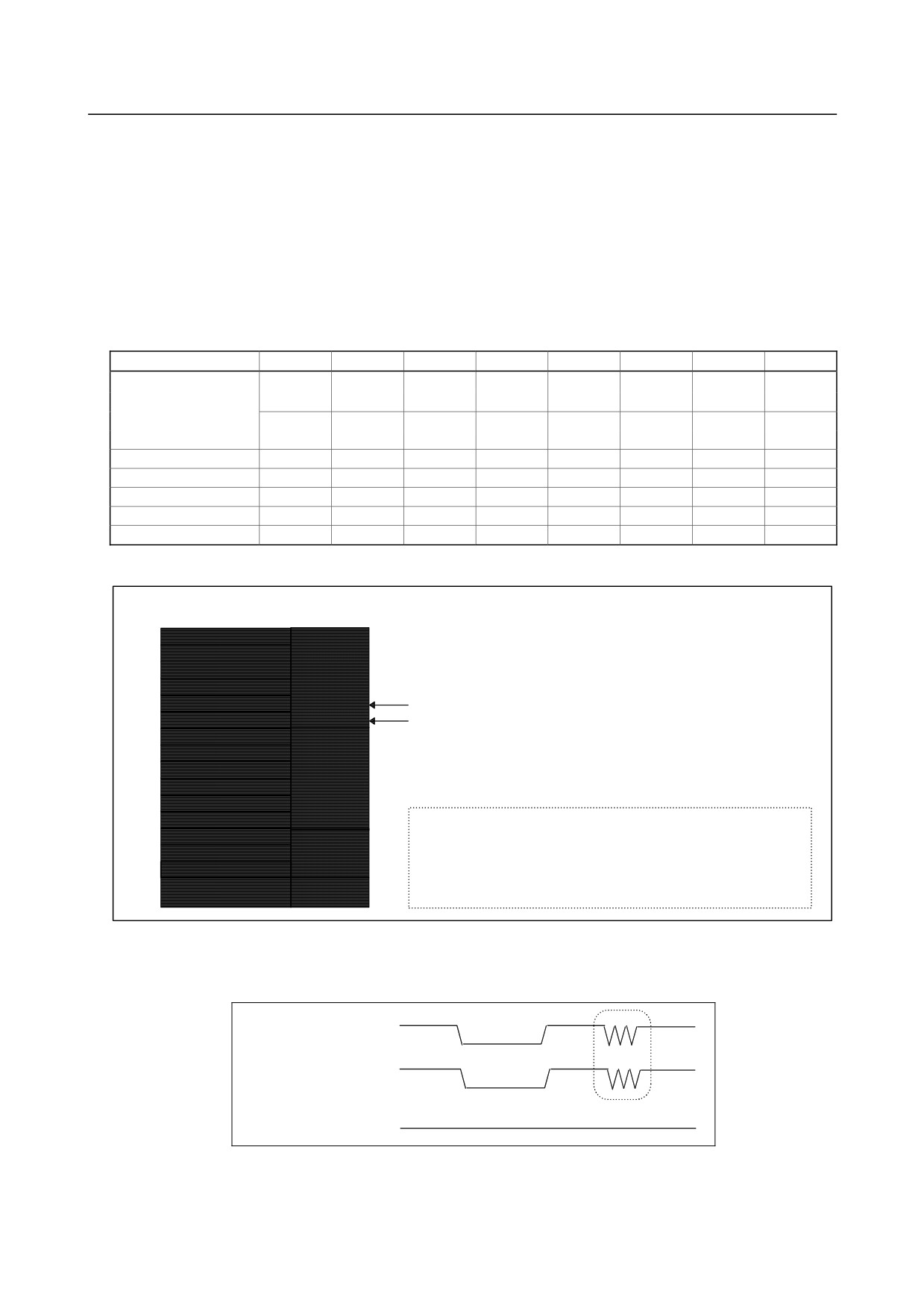
For the operator's panel I/O module, I/O addresses are mapped as follows.
DI space map
DO space map
Xm
Yn
Xm+1
Yn+1
Output signal
Xm+2
Yn+2
Input signal
Xm+3
Yn+3
Xm+4
Xm+5
Xm+6
Xm+7
Xm+8
Not used
Xm+9
Xm+10
Xm+11
Xm+12 (for 1st MPG)
Xm+13 (for 2nd MPG)
MPG
Xm+14 (for 3rd MPG)
Xm+15 (DO alarm
DO alarm
detection)
detection
Basically, this 48/32-point I/O module is allocated a group of DI addresses (16 bytes) and a group of DO
addresses (4 bytes). This address allocation is explained below.
The MPG interface (MPG counter) occupies DI space from Xm+12 through Xm+14. These addresses
are fixed, and Xm+12 through Xm+14 must be allocated as a DI work area to enable the use of the MPG.
Therefore, when using an MPG for the i series CNC, allocate DI addresses in units of 16 bytes.
Do not use the DI space from Xm+12 through Xm+14 for Ladder; the CNC processes the MPG counter
value directly.
- 180 -
B-64303EN/03
9.CONNECTION OF I/O Link SLAVE DEVICES
DI address Xm+15 is used for detecting overcurrent and overheating alarms that occur in the IC used in
the DO driver.
(For details, see the section describing the detection of DO (output signal) alarms.)
This address is fixed, and must be allocated as a work area before it can be used. When using this area,
therefore, allocate DI addresses in units of 16 bytes.
Basically, I/O addresses can be allocated to the 48/32-point I/O module freely. When allocating DI
addresses, however, consider also the fixed addresses that are directly supervised by the CNC, and keep
the following in mind.
Fixed addresses directly supervised by the CNC (Example: Series 0i)
7
6
5
4
3
2
1
0
X0004
SKIP
ESKIP
-MIT2
+MIT2
-MIT1
+MIT1
XAE2
XAE1
SKIP6
SKIP5
SKIP4
SKIP3
SKIP2
SKIP8
SKIP7
SKIP
ESKIP
SKIP5
SKIP4
SKIP3
XAE3
XAE2
XAE1
SKIP6
SKIP2
SKIP8
SKIP7
X0005
X0006
X0007
X0008
*ESP
X0009
*DEC5
*DEC4
*DEC3
*DEC2
*DEC1
The upper row indicates the T series (first path), and the lower row indicates the M series.
When DI addresses are allocated in units of 16 bytes, starting at X0004
X0004
X0005
X0006
Input signal
X0007
X0008
*ESP fixed signal
X0009
*DECn fixed signal
X0010
X0011
X0012
Not used
X0013
X0014
X0015
X0016 (for 1st MPG)
Allocating DI addresses from X0004 allows the fixed signals,
X0017 (for 2nd MPG)
MPG
such as SKIP and *DECn, to be used and the *ESP fixed
signal to be allocated to an address for which the common
X0018 (for 3rd MPG)
voltage in fixed to 24 V.
X0019 (DO alarm
DO alarm
detection)
detection
Turning the DO (output signal) power on and off (DOCOM)
All the DO signals can be turned off simultaneously by turning off (opening) the DO (output signal)
power supply pin "DOCOM". Doing so causes the DO signal status to change as shown below.
ON
DOCOM
OFF
When DO is ON in
ON
the sequence
OFF
When DO is OFF in
ON
the sequence
OFF
- 181 -
9.CONNECTION OF I/O Link SLAVE DEVICES
B-64303EN/03
NOTE
When the DO signal is in the ON state in the sequence, the ON or OFF state of
the DOCOM pin determines the state of the signal, as shown within dotted lines
in the above figure. Do not turn off the +24 V supply provided by the CPD1 to
the I/O module during the operation. Turning off the +24 V supply causes a
CNC communication alarm. When turning on the power, the +24 V supply to
the I/O module must be turned on before or at the same time as the power
supply to the CNC. When turning off the power, the +24 V supply to the I/O
module must be turned off after or at the same time as the power supply to the
CNC.
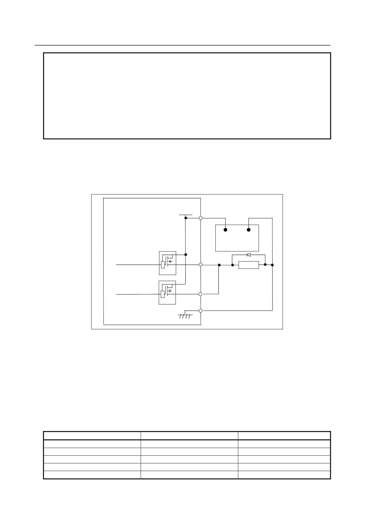
Parallel DO (output signal) connection
The DO load current can be doubled by connecting two DO points in parallel and turning them on and off
simultaneously in sequence, as shown in the figure below. The maximum load current per DI point is
200 mA. Connecting two DO points in parallel and turning them on at the same time produces a current
of 400 mA. Note that, however, when two DO points are connected in parallel, the leakage current also
doubles when they are off (max. 40 mA).
CE56(A24, B24, A25, B25)
DOCOM
CE57(A24, B24, A25, B25)
+24V
0V
+24V stabilized
power supply
Relay
DV
DV
DO (output signal) alarm detection
The DO driver of the I/O module is capable of detecting an overcurrent and measuring its own
temperature. If an accident, such as the connecting of the cable to ground, causes an abnormal increase
in the load current or in the driver temperature, a protection circuit, which is provided for each DO driver
(1 byte), is activated and keeps the DO signal for the relevant 1 byte in the OFF state until the cause of
the problem is eliminated. Even if this occurs, the CNC and I/O module continue operating. The DI
address (Xm+15) identifies the DO driver which has detected the alarm. The following table shows the
correspondence between the DI address (Xm+15) bits and the DO addresses. Bit value "1" indicates that
the corresponding DO driver has detected an alarm. The contents of the Xm+15 area can be checked by
using the DGN screen of the CNC or by performing alarm processing for the area in advance by using
Ladder. This helps alarm detection and recovery.
Alarm detection address and bit
DO address
Remarks
Xm+15.0
Yn+0
Xm+15.1
Yn+1
Xm+15.2
Yn+2
Xm+15.3
Yn+3
Xm+15.4
Yn+4
Reserved
- 182 -
B-64303EN/03
9.CONNECTION OF I/O Link SLAVE DEVICES
Alarm detection address and bit
DO address
Remarks
Xm+15.5
Yn+5
Reserved
Xm+15.6
Yn+6
Reserved
Xm+15.7
Yn+7
Reserved
9.5
I/O MODULE TYPE-2 FOR CONNECTOR PANEL
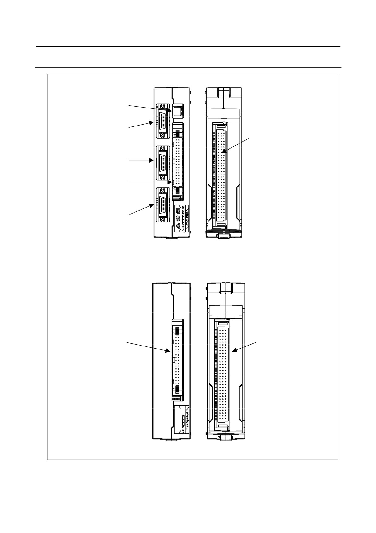
9.5.1
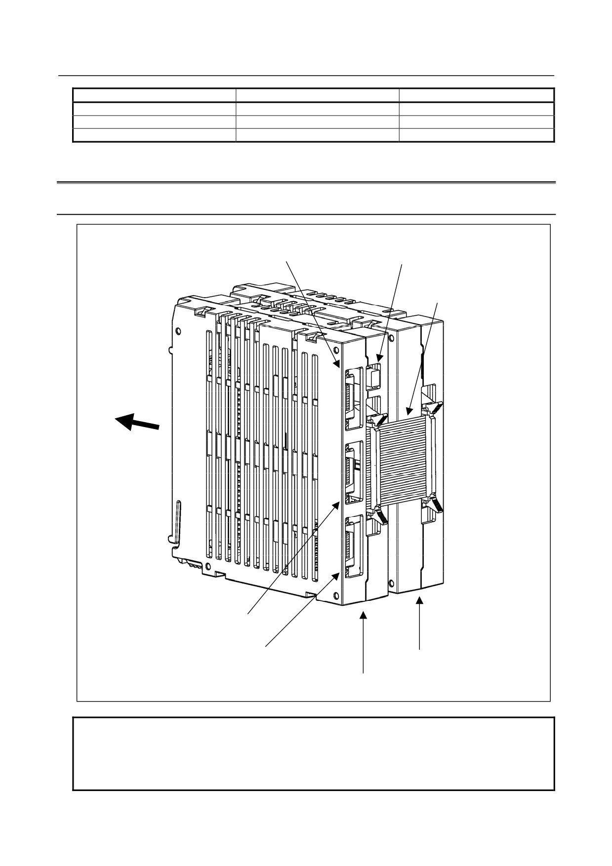
Configuration
I/O Link connector
Fuse
Inter-module flat
cable
Installed on
connector panel
PC board
I/O Link connector
Connector for manual pulse generator
Expansion module
Basic module
NOTE
Be sure to install the basic module on the left side of the expansion module.
This unit cannot be installed on the DIN rail.
In a maximum configuration, one basic module plus one expansion module can
be installed per group as shown above (DI/DO=96/64).
- 183 -
9.CONNECTION OF I/O Link SLAVE DEVICES
B-64303EN/03
9.5.2
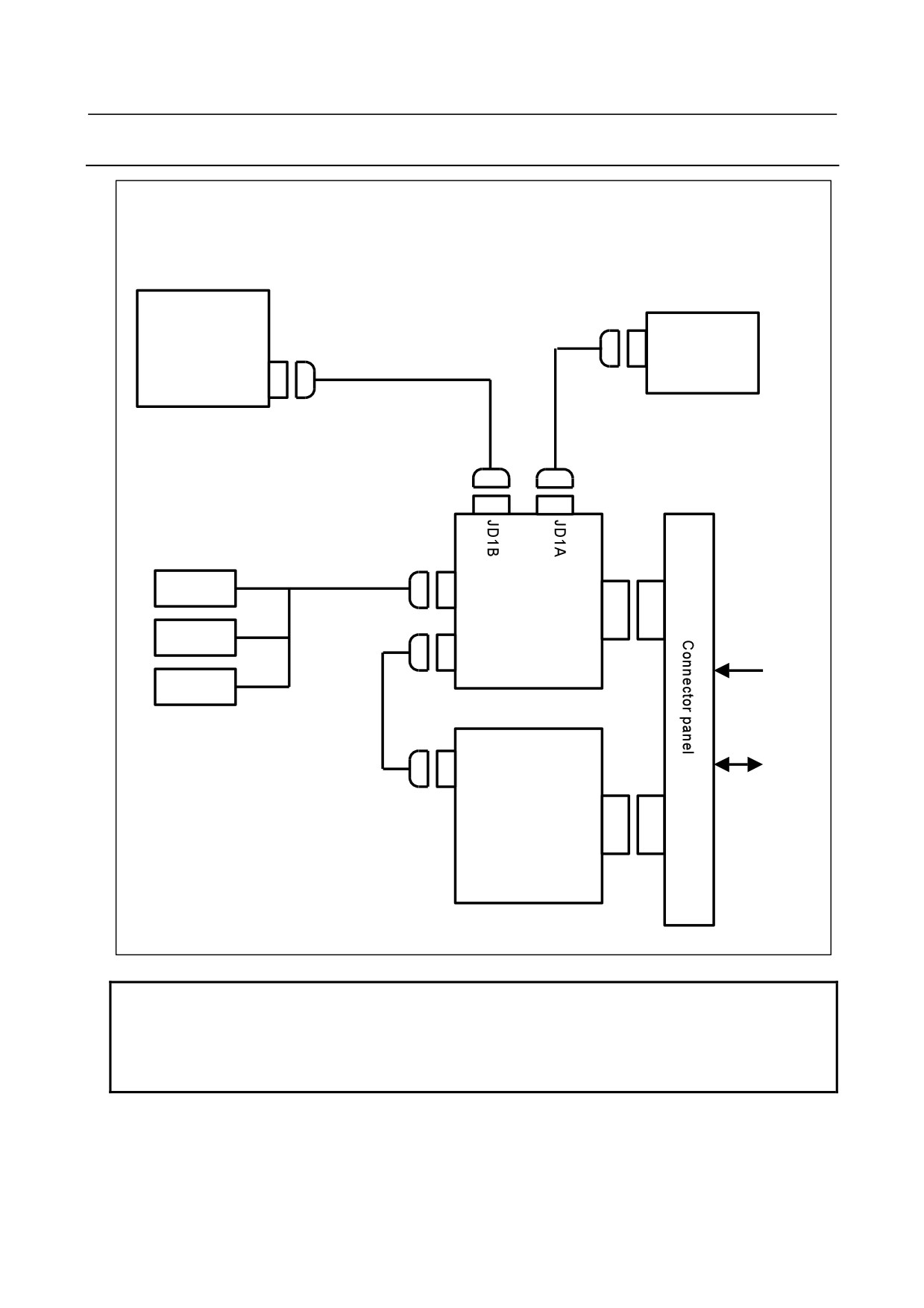
Connector Layout Diagram
Basic module
Fuse
I/O Link connector
(JD1B)
Connector for connector
panel PC board
connection (CB161)
I/O Link connector
(JD1A)
Connector for
inter-module connection
(CA101)
Connector for manual
pulse generator
(JA3)
Front
Rear
Expansion module
Connector for
Connector for connector
inter-module
panel PC board
connection (CA102)
connection (CB162)
Front
Rear
- 184 -
B-64303EN/03
9.CONNECTION OF I/O Link SLAVE DEVICES
9.5.3
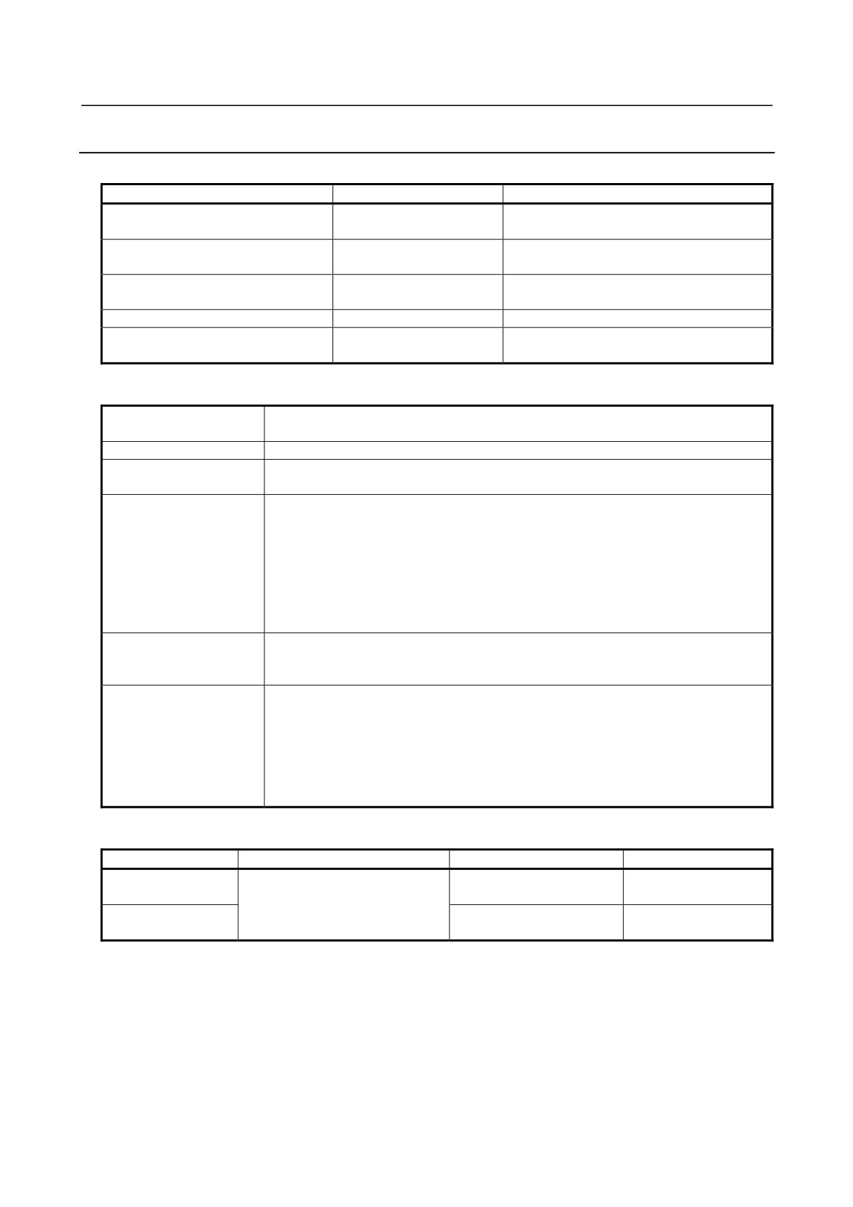
Connection Diagram
CNC or preceding
I/O Link slave unit
Following I/O Link
slave unit
JD1B
I/O Link
JD1A(JD51A)
JA3
MPG
CB161
+24V
MPG
CA101
power
MPG
Basic module
Flat
cable
CA102
DI/DO
on
machine
CB161
side
Expansion module
NOTE
The maximum configuration of a group consists of one basic module plus one
expansion module as shown above. At this time, the number of input points is
96, and the number of output points is 64. To add points, connect an additional
slave onto the I/O Link.
- 185 -
9.CONNECTION OF I/O Link SLAVE DEVICES
B-64303EN/03
9.5.4
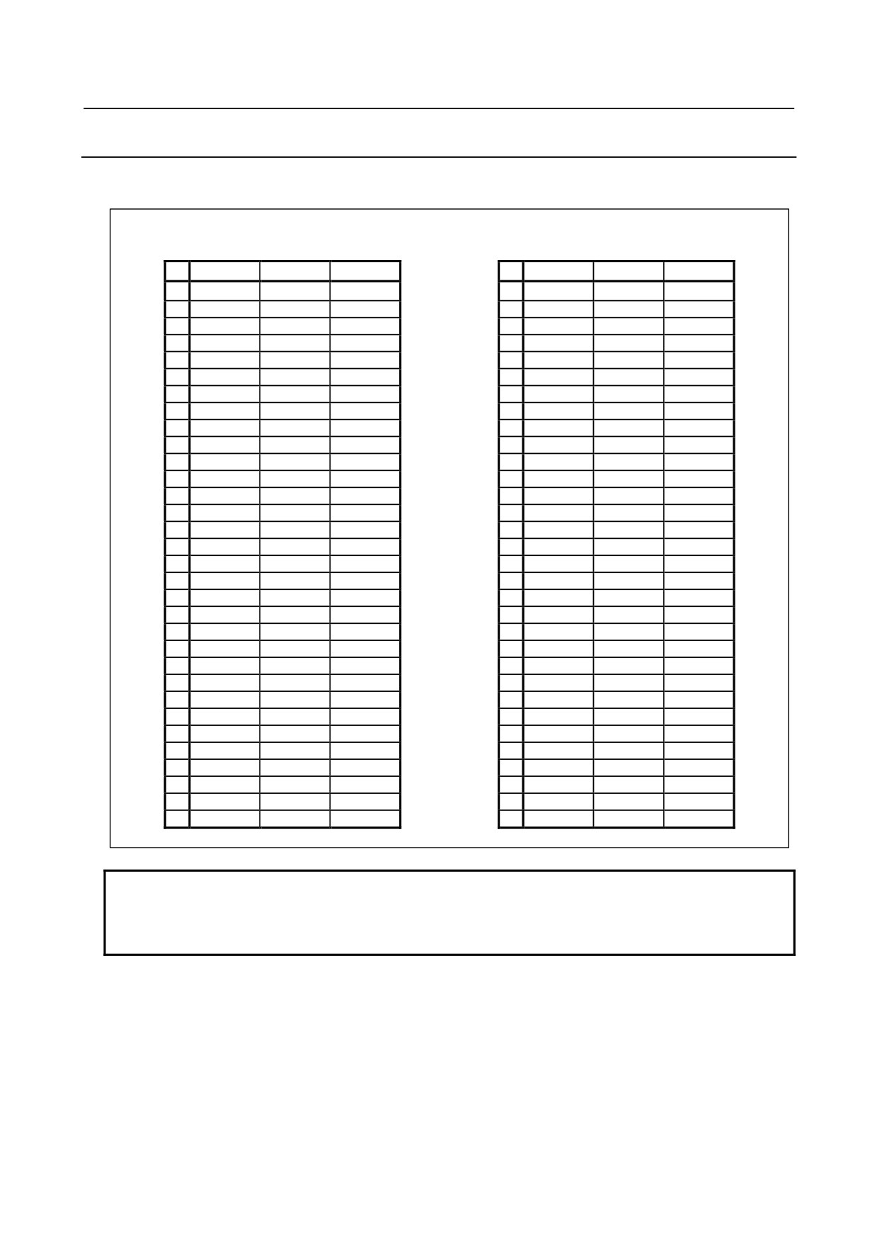
Module Specifications
Types of modules
Name
Drawing No.
Specifications
Distribution I/O type-2
A03B-0815-C040
DI/DO=48/32
(Basic module B1)
With MPG interface
Distribution I/O type-2
A03B-0815-C041
DI/DO=48/32
(Basic module B2)
Without MPG interface
Distribution I/O type-2
A03B-0815-C042
DI/DO=48/32
(Expansion module E1)
Fuse (accessory)
A03B-0815-K002
1 A (for basic module)
Inter-module flat cable
A03B-0815-K102
Cable length: 35 mm
Module interval: 5 mm
Installation conditions
Ambient temperature
Operation: 0°C to 55°C
for the unit
Storage and transportation: -20°C to 60°C
Temperature change
1.1°C/minute maximum
Humidity
Normal condition: 75% (relative humidity) or less, no condensation
Short term (within one month): 95% or less (relative humidity), no condensation
Vibration
Operation: 0.5 G or less. FANUC performs evaluation test under the following
conditions:
10 Hz to 58 Hz: 0.075 mm (amplitude)
58 Hz to 500 Hz: 1 G
Vibration direction: X, Y, and Z
Number of sweeps: 10 cycles
Compliance with IEC68-2-6
Non-operation: 1.0 G or less
Atmosphere
Normal machining factory environment (For use in an environment with relatively high
levels of dust, coolant, organic solutions, and so forth, additional measures are
required.)
Other conditions
(1) Use each I/O module in a completely sealed cabinet.
(2) For ventilation within each I/O module, allow a clearance of 40 mm or more
between modules. Moreover, allow a clearance of 50 mm or more above and
below each module.
Never place a device that generates a large amount of heat below an I/O module.
(3) When mounting I/O modules, ensure that the basic module is mounted on the left
side when viewed from the flat cable.
Power supply rating
Module
Power supply voltage
Power supply rating
Remarks
Basic module
24 VDC ±10% is fed through
0.3A+7.3mA×DI
Number of DI points
CB161 and CB162; ±10%
with DI=ON
Expansion module
includes momentary variations
0.2A+7.3mA×DI
Number of DI points
and ripples.
with DI=ON
As a guideline for heat dissipation, assume [power supply rating × 24 (W)].
- 186 -
B-64303EN/03
9.CONNECTION OF I/O Link SLAVE DEVICES
9.5.5
DI/DO Connector Pin Assignment
This subsection describes the DI/DO connector
pin assignment of the basic module and expansion
module.
Basic module
Expansion module
CB161 (HONDA MRF-96ML)
CB162 (HONDA MRF-96ML)
A
B
C
A
B
C
32
+24V
+24V
+24V
32
+24V
+24V
+24V
31
0V
0V
0V
31
0V
0V
0V
30
0V
0V
0V
30
0V
0V
0V
29
DICOM0
Xm+0.0
29
DICOM6
Xm+6.0
28
Xm+0.1
Xm+0.2
Xm+0.3
28
Xm+6.1
Xm+6.2
Xm+6.3
27
Xm+0.4
Xm+0.5
Xm+0.6
27
Xm+6.4
Xm+6.5
Xm+6.6
26
Xm+0.7
Xm+1.0
Xm+1.1
26
Xm+6.7
Xm+7.0
Xm+7.1
25
Xm+1.2
Xm+1.3
Xm+1.4
25
Xm+7.2
Xm+7.3
Xm+7.4
24
Xm+1.5
Xm+1.6
Xm+1.7
24
Xm+7.5
Xm+7.6
Xm+7.7
23
Xm+2.0
Xm+2.1
Xm+2.2
23
Xm+8.0
Xm+8.1
Xm+8.2
22
Xm+2.3
Xm+2.4
Xm+2.5
22
Xm+8.3
Xm+8.4
Xm+8.5
21
Xm+2.6
Xm+2.7
Xm+3.0
21
Xm+8.6
Xm+8.7
Xm+9.0
20
Xm+3.1
Xm+3.2
Xm+3.3
20
Xm+9.1
Xm+9.2
Xm+9.3
19
Xm+3.4
Xm+3.5
Xm+3.6
19
Xm+9.4
Xm+9.5
Xm+9.6
18
Xm+3.7
Xm+4.0
Xm+4.1
18
Xm+9.7
Xm+10.0
Xm+10.1
17
Xm+4.2
Xm+4.3
Xm+4.4
17
Xm+10.2
Xm+10.3
Xm+10.4
16
Xm+4.5
Xm+4.6
Xm+4.7
16
Xm+10.5
Xm+10.6
Xm+10.7
15
Xm+5.0
Xm+5.1
Xm+5.2
15
Xm+11.0
Xm+11.1
Xm+11.2
14
Xm+5.3
Xm+5.4
Xm+5.5
14
Xm+11.3
Xm+11.4
Xm+11.5
13
Xm+5.6
Xm+5.7
DICOM3
13
Xm+11.6
Xm+11.7
DICOM9
12
Yn+3.5
Yn+3.6
Yn+3.7
12
Yn+7.5
Yn+7.6
Yn+7.7
11
Yn+3.2
Yn+3.3
Yn+3.4
11
Yn+7.2
Yn+7.3
Yn+7.4
10
Yn+2.7
Yn+3.0
Yn+3.1
10
Yn+6.7
Yn+7.0
Yn+7.1
9
Yn+2.4
Yn+2.5
Yn+2.6
9
Yn+6.4
Yn+6.5
Yn+6.6
8
Yn+2.1
Yn+2.2
Yn+2.3
8
Yn+6.1
Yn+6.2
Yn+6.3
7
DOCOM23
DOCOM23
Yn+2.0
7
DOCOM67
DOCOM67
Yn+6.0
6
Yn+1.5
Yn+1.6
Yn+1.7
6
Yn+5.5
Yn+5.6
Yn+5.7
5
Yn+1.2
Yn+1.3
Yn+1.4
5
Yn+5.2
Yn+5.3
Yn+5.4
4
Yn+0.7
Yn+1.0
Yn+1.1
4
Yn+4.7
Yn+5.0
Yn+5.1
3
Yn+0.4
Yn+0.5
Yn+0.6
3
Yn+4.4
Yn+4.5
Yn+4.6
2
Yn+0.1
Yn+0.2
Yn+0.3
2
Yn+4.1
Yn+4.2
Yn+4.3
1
DOCOM01
DOCOM01
Yn+0.0
1
DOCOM45
DOCOM45
Yn+4.0
NOTE
1 Each of Xm and Yn represents the start address of the module on the I/O Link.
2 The A32, B32, and C32 pins of each connector are used to feed 24 V to the
module externally. Be sure to connect these pins.
- 187 -
9.CONNECTION OF I/O Link SLAVE DEVICES
B-64303EN/03
9.5.6
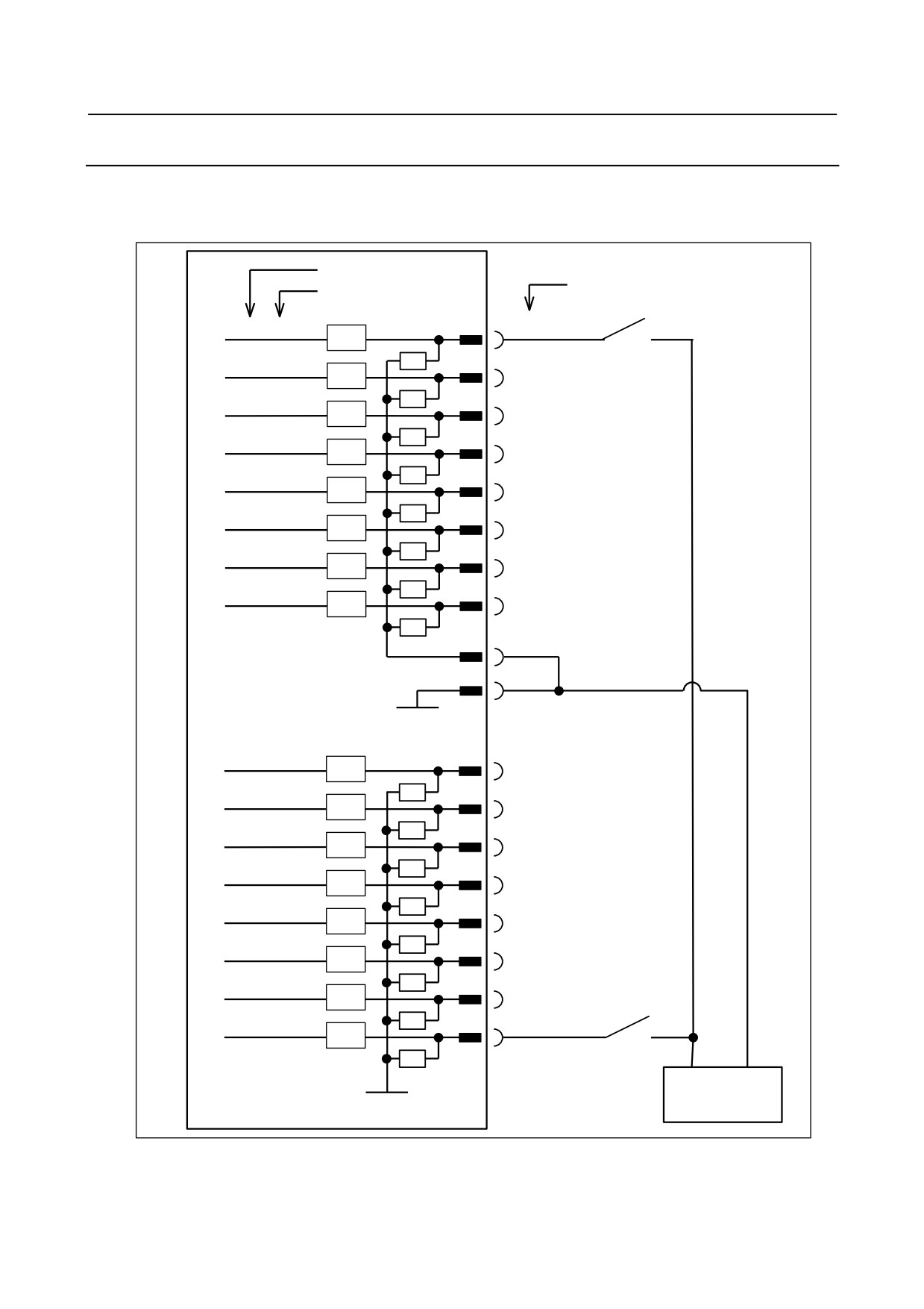
DI (Input Signal) Connection
This subsection describes the DI (input signal) connections of the basic module and expansion modules.
○ 96 points maximum (Up to 48 points (basic
module) + 48 points (expansion module)
can
be
connected.)
Address number
Pin number
Bit number
Xm+0.0
CB161(C29)
RV
Xm+0.1
RV
CB161(A28)
Xm+0.2
CB161(B28)
RV
Xm+0.3
RV
CB161(C28)
Xm+0.4
CB161(A27)
RV
Xm+0.5
RV
CB161(B27)
Xm+0.6
CB161(C27)
RV
Xm+0.7
RV
CB161(A26)
Xm+0.0 to Xm+0.7 are DI
CB161(B29
signals for which a common
DICOM0
voltage can be selected.
CB161(A31,B31,C31,
0V
A30,B30,C30)
Xm+1.0
CB161(B26)
RV
Xm+1.1
CB161(C26)
RV
Xm+1.2
CB161(A25)
RV
Xm+1.3
CB161(B25)
RV
Xm+1.4
CB161(C25)
RV
Xm+1.5
CB161(A24)
RV
Xm+1.6
CB161(B24)
RV
Xm+1.7
CB161(C24)
RV
+24V
0V
0V
+24 V stabilized
power supply
- 188 -
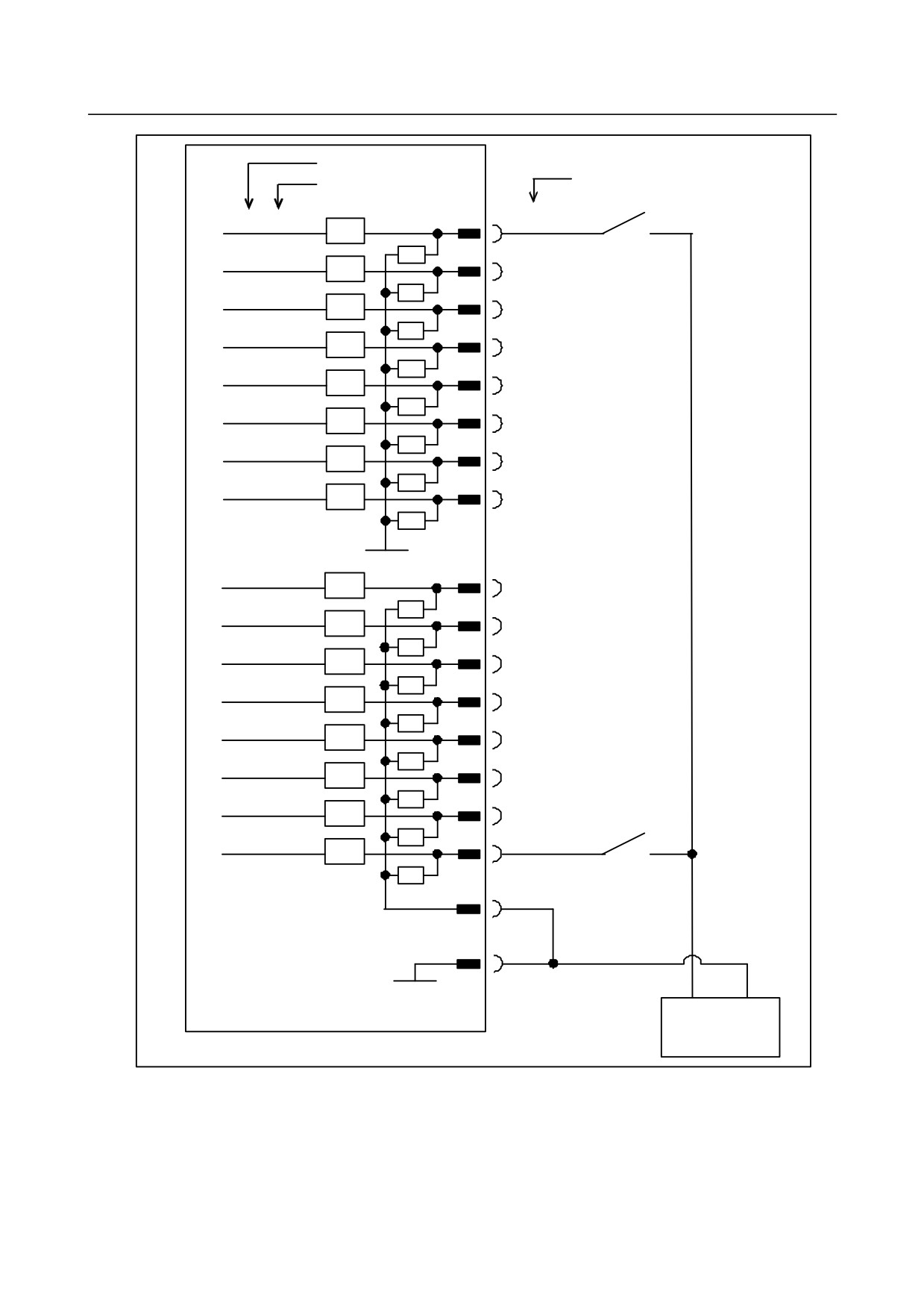
B-64303EN/03
9.CONNECTION OF I/O Link SLAVE DEVICES
Address number
Pi n number
Bit numb er
Xm+2.0
CB161(A23)
RV
Xm+2.1
CB161(B23)
RV
Xm+2.2
CB161(C23)
RV
Xm+2.3
CB161(A22)
RV
Xm+2.4
CB161(B22)
RV
Xm+2.5
CB161(C22)
RV
Xm+2.6
CB161(A21)
RV
Xm+2.7
CB16 1(B21)
RV
0V
Xm+3.0
CB161(C21)
RV
Xm+3.1
CB161(A20)
RV
Xm+3.2
CB161(B20)
RV
Xm+3.3
CB161(C20)
RV
Xm+3.4
CB161(A19)
RV
Xm+3.5
CB161(B19)
RV
Xm+3.6
CB161(C19)
RV
Xm+3.7
CB161(A18)
RV
Xm+3.0 to Xm+3.7 are DI
CB161(C1
signals for which a common
DICOM3
voltage c an be selected.
CB161(A31,B31,C31,
0V
A30,B30,C30)
+24V
0V
+24V stabilized
power supply
- 189 -
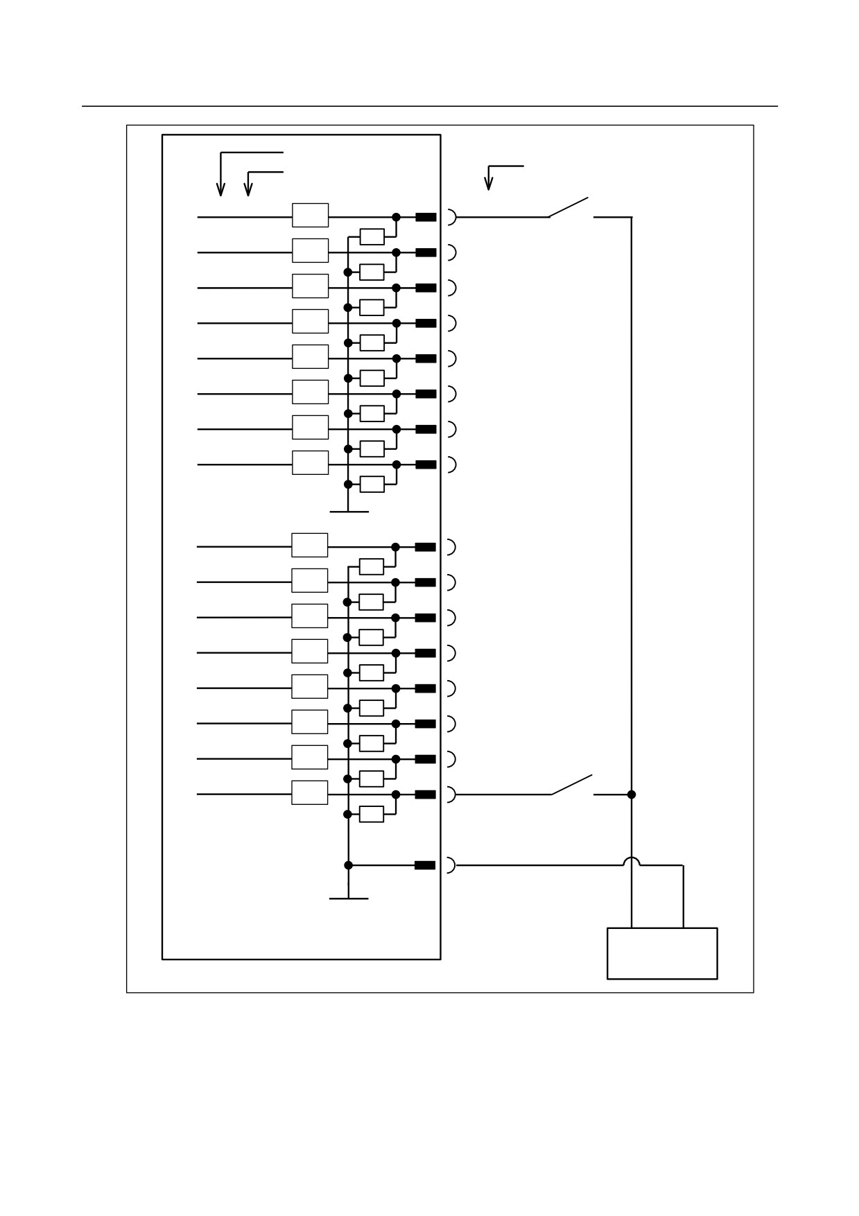
9.CONNECTION OF I/O Link SLAVE DEVICES
B-64303EN/03
Address number
Pin number
Bit number
Xm+4.0
CB161(B18)
RV
Xm+4.1
CB161(C18)
RV
Xm+4.2
CB161(A17)
RV
Xm+4.3
CB161(B17)
RV
Xm+4.4
CB161(C17)
RV
Xm+4.5
CB161(A16)
RV
Xm+4.6
CB161(B16)
RV
Xm+4.7
CB161(C16)
RV
0V
Xm+5.0
CB161(A15)
RV
Xm+5.1
CB161(B15)
RV
Xm+5.2
CB161(C15)
RV
Xm+5.3
CB161(A14)
RV
Xm+5.4
CB161(B14)
RV
Xm+5.5
CB161(C14)
RV
Xm+5.6
CB161(A13)
RV
Xm+5.7
CB161(B13)
RV
CB161(A31,B31,C31,
A30,B30,C30)
0V
+24V
0V
+24 V stabilized
power supply
- 190 -
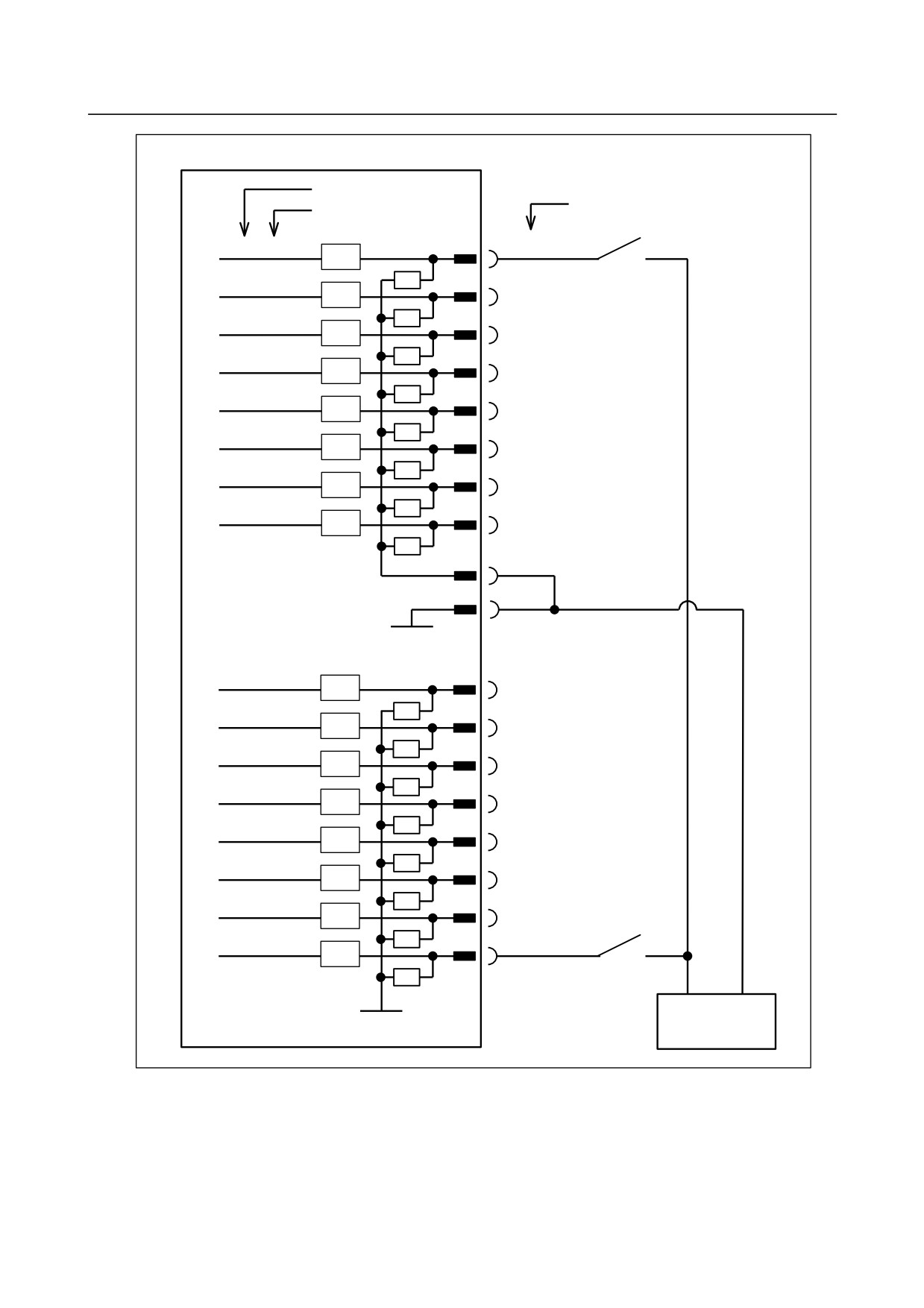
B-64303EN/03
9.CONNECTION OF I/O Link SLAVE DEVICES
Address number
Pin number
Bit number
Xm+6.0
CB162(C29)
RV
Xm+6.1
CB162(A28)
RV
Xm+6.2
CB162(B28)
RV
Xm+6.3
CB162(C28)
RV
Xm+6.4
CB162(A27)
RV
Xm+6.5
CB162(B27)
RV
Xm+6.6
CB162(C27)
RV
Xm+6.7
CB162(A26)
RV
Xm+6.0 to Xm+6.7 are DI
CB162(B29)
signals for which a common
voltage can be selected.
CB162(A31,B31,C31,
0V
A30,B30,C30)
Xm+7.0
CB162(B26)
RV
Xm+7.1
CB162(C26)
RV
Xm+7.2
CB162(A25)
RV
Xm+7.3
CB162(B25)
RV
Xm+7.4
CB162(C25)
RV
Xm+7.5
CB162(A24)
RV
Xm+7.6
CB162(B24)
RV
Xm+7.7
CB162(C24)
RV
+24V
0V
0V
+24 V stabilized
power supply
- 191 -
9.CONNECTION OF I/O Link SLAVE DEVICES
B-64303EN/03
Address number
Pin number
Bit number
Xm+8.0
CB162(A23)
RV
Xm+8.1
CB162(B23)
RV
Xm+8.2
CB162(C23)
RV
Xm+8.3
CB162(A22)
RV
Xm+8.4
CB162(B22)
RV
Xm+8.5
CB162(C22)
RV
Xm+8.6
CB162(A21)
RV
Xm+8.7
CB162(B21)
RV
0V
Xm+9.0
CB162(C21)
RV
Xm+9.1
CB162(A20)
RV
Xm+9.2
CB162(B20)
RV
Xm+9.3
CB162(C20)
RV
Xm+9.4
CB162(A19)
RV
Xm+9.5
CB162(B19)
RV
Xm+9.6
CB162(C19)
RV
Xm+9.7
CB162(A18)
RV
Xm+9.0 to Xm+9.7 are DI
CB162(C13)
signals for which a common
voltage can be selected.
DICOM9
CB162(A31,B31,C31,
0V
A30,B30,C30)
+24V
0V
+24 V stabilized
power supply
- 192 -
B-64303EN/03
9.CONNECTION OF I/O Link SLAVE DEVICES
Address number
Pin number
Bit number
Xm+10.0
CB162(B18)
RV
Xm+10.1
CB162(C18)
RV
Xm+10.2
CB162(A17)
RV
Xm+10.3
CB162(B17)
RV
Xm+10.4
CB162(C17)
RV
Xm+10.5
CB162(A16)
RV
Xm+10.6
CB162(B16)
RV
Xm+10.7
CB162(C16)
RV
0V
Xm+11.0
CB162(A15)
RV
Xm+11.1
CB162(B15)
RV
Xm+11.2
CB162(C15)
RV
Xm+11.3
CB162(A14)
RV
Xm+11.4
CB162(B14)
RV
Xm+11.5
CB162(C14)
RV
Xm+11.6
CB162(A13)
RV
Xm+11.7
CB162(B13)
RV
CB162(A31,B31,C31,
A30,B30,C30)
0V
+24V
0V
+24 V stabilized
power supply
- 193 -
9.CONNECTION OF I/O Link SLAVE DEVICES
B-64303EN/03
9.5.7
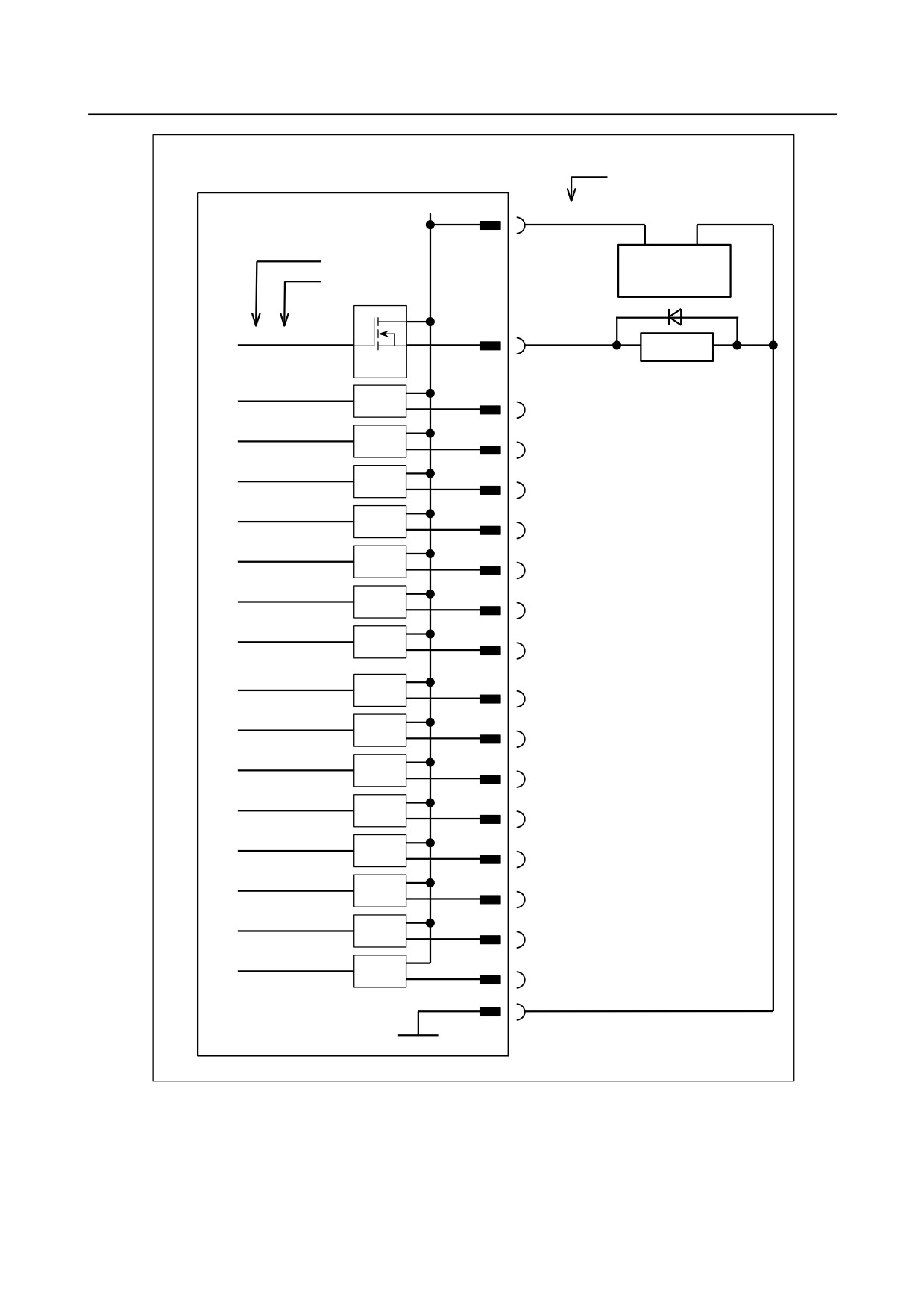
DO (Output Signal) Connection
This subsection describes the DO (output signal) connections of the basic module and expansion module.
○ 64 points maximum (Up to 32 points (basic
module) + 32 points (expansion module)
can
be
connected.)
Pin number
DOCOM01
CB161(A01,B01)
Address number
+24V
0V
Bit number
+24 V stabilized
power supply
Yn+0.0
CB161(C01)
Relay
DV
Yn+0.1
DV
CB161(A02)
Yn+0.2
DV
CB161(B02)
Yn+0.3
DV
CB161(C02)
Yn+0.4
DV
CB161(A03)
Yn+0.5
DV
CB161(B03)
Yn+0.6
DV
CB161(C03)
Yn+0.7
DV
CB161(A04)
Yn+1.0
DV
CB161(B04)
Yn+1.1
DV
CB161(C04)
Yn+1.2
DV
CB161(A05)
Yn+1.3
DV
CB161(B05)
Yn+1.4
DV
CB161(C05)
Yn+1.5
DV
CB161(A06)
Yn+1.6
DV
CB161(B06)
Yn+1.7
DV
CB161(C06)
CB161(A31,B31,C31,
A30,B30,C30)
0V
- 194 -
B-64303EN/03
9.CONNECTION OF I/O Link SLAVE DEVICES
Pin number
DOCOM23
CB161(A07,B07)
+24V
0V
Address number
+24 V stabilized
Bit number
power supply
Yn+2.0
CB161(C07)
Relay
DV
Yn+2.1
DV
CB161(A08)
Yn+2.2
DV
CB161(B08)
Yn+2.3
DV
CB161(C08)
Yn+2.4
DV
CB161(A09)
Yn+2.5
DV
CB161(B09)
Yn+2.6
DV
CB161(C09)
Yn+2.7
DV
CB161(A10)
Yn+3.0
DV
CB161(B10)
Yn+3.1
DV
CB161(C10)
Yn+3.2
DV
CB161(A11)
Yn+3.3
DV
CB161(B11)
Yn+3.4
DV
CB161(C11)
Yn+3.5
DV
CB161(A12)
Yn+3.6
DV
CB161(B12)
Yn+3.7
DV
CB161(C12)
CB161(A31,B31,C31,
A30,B30,C30)
0V
- 195 -
9.CONNECTION OF I/O Link SLAVE DEVICES
B-64303EN/03
Pin number
DOCOM45
CB162(A01,B01)
Address number
+24V
0V
Bit number
+24 V stabilized
power supply
Yn+4.0
CB162(C01)
Relay
DV
Yn+4.1
DV
CB162(A02)
Yn+4.2
DV
CB162(B02)
Yn+4.3
DV
CB162(C02)
Yn+4.4
DV
CB162(A03)
Yn+4.5
DV
CB162(B03)
Yn+4.6
DV
CB162(C03)
Yn+4.7
DV
CB162(A04)
Yn+5.0
DV
CB162(B04)
Yn+5.1
DV
CB162(C04)
Yn+5.2
DV
CB162(A05)
Yn+5.3
DV
CB162(B05)
Yn+5.4
DV
CB162(C05)
Yn+5.5
DV
CB162(A06)
Yn+5.6
DV
CB162(B06)
Yn+5.7
DV
CB162(C06)
CB162(A31,B31,C31,
A30,B30,C30)
0V
- 196 -