FANUC Series 0i-MODEL D, Series 0i Mate-MODEL D. CONNECTION MANUAL (HARDWARE) - page 5
B-64303EN/03
7.SERVO INTERFACE
7.3.5
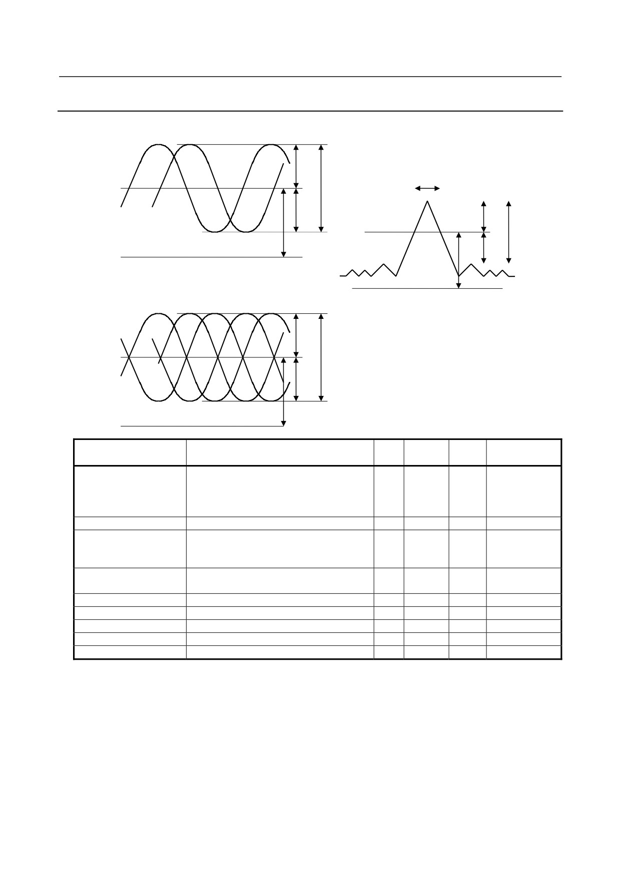
Input Signal Specifications
A/B (Type I)
VB
a/2
TZ LZ
VXA VXB
Z
VA
a/2
c/2
Effective
component c
VOA,VOB
VOZ
c/2
0V
A/B (Type II)
0V
VB
VA
b/2
b
VXA
b/2
VXB
VOA,VOXA
0V
VOB,VOXB
Min.
Standard
Max.
Item
Symbol
Unit
spec.
spec.
spec.
Amplitude (phase A/B)
Type I a of phase A and phase B
0.6
1.0
1.5
VP-P
Type II Sum of b of phase A and b of
phase XA Sum of b of phase B and b of
phase XB
Amplitude (phase Z)
Sum of c of Z and c of XZ (analog signal)
0.2
0.4
-
V
Center value
Type I VOA,VXA ,VOB,VXB
(DC level)
Type II VOA,VOXA ,VOB,VOXB
2.0
2.5
3.0
V
VOZ,VOXZ
Offset voltage
Type I VOA-VXA , VOB-VXB
-0.1
0
+0.1
V
(phase A/B)
Type II VOA-VOXA , VOB-VOXB
Offset voltage (phase Z)
VOZ-VOXZ
-0.05
0
+0.05
V
Pulse width of phase Z
TZ
600
-
-
nSec
Length of phase Z
LZ
1/4
-
-
Pitch of A (or B)
Input impedance
100
120
140
Ω
Input frequency
-
-
200
kHz
* The detection precision depends on the precision of signals from the encoder.
- 107 -
7.SERVO INTERFACE
B-64303EN/03
7.3.6
Connection of Battery for Absolute Position Detector
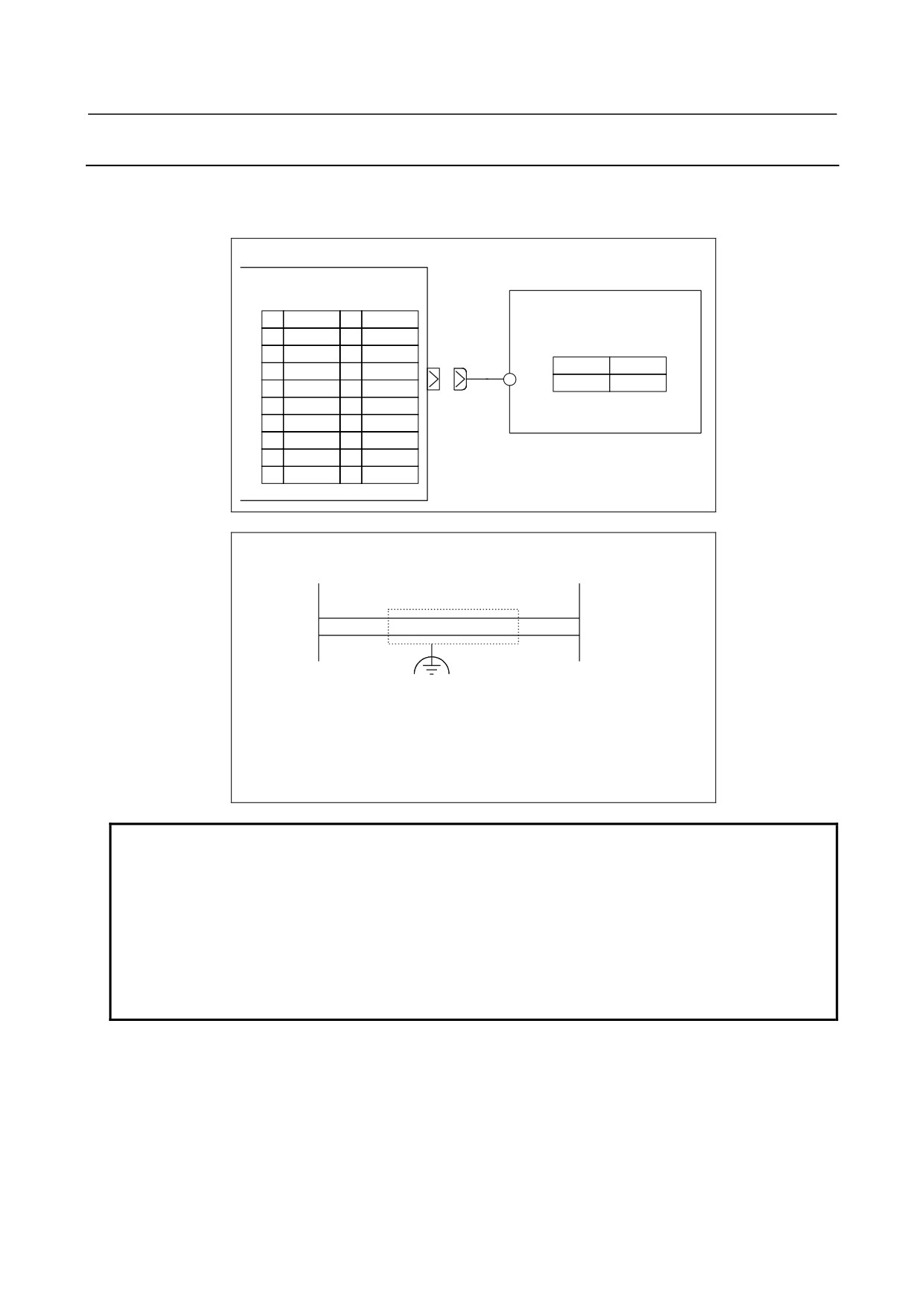
When a separate absolute position detector that requires battery backup is connected to an additional unit,
a battery case for the separate absolute pulse coder must be connected to JA4A of the analog input
separate detector interface unit.
Analog input separate detector
Battery case for the separate
interface unit
absolute pulse coder
JA4A
(PCR-EV20MDT)
01
11
02
12
(M3 terminal)
03
0V
13
+
-
04
14
+6V
0V
05
15
06
16
07
+6V
17
08
18
09
19
10
20
Cable connection
JA4A
Battery case
7
+
+6V
+6V
3
-
0V
0V
RECOMMENDED CABLE MATERIAL:
≥0.2 mm2 (7/0.18)
Recommended connectors:
PCR-E20FA (Honda Tsushin Kogyo)
FI30-20S (Hirose Electric)
FCN-247J020-G/E (Fujitsu)
52622-2011 (Molex)
NOTE
If the cable is connected to JA4A when the separate absolute pulse coder
battery case contains the battery, the battery voltage is applied to the battery
power supply pin (+6 V) for each of the feedback connectors (JF105 to JF108).
In this case, if the battery line and 0 V are short-circuited, the battery may heat
up or the protection circuit within the separate detector interface unit may fail.
First, make sure the battery case contains no battery or the cable is not
connected to JA4A. Then, complete all cabling work and confirm cables are
correctly connected. Finally, place the battery or connect the cable to JA4A.
- 108 -
B-64303EN/03
7.SERVO INTERFACE
7.3.7
Connection Between the Analog Input Separate Detector
Interface Unit and Additional Unit
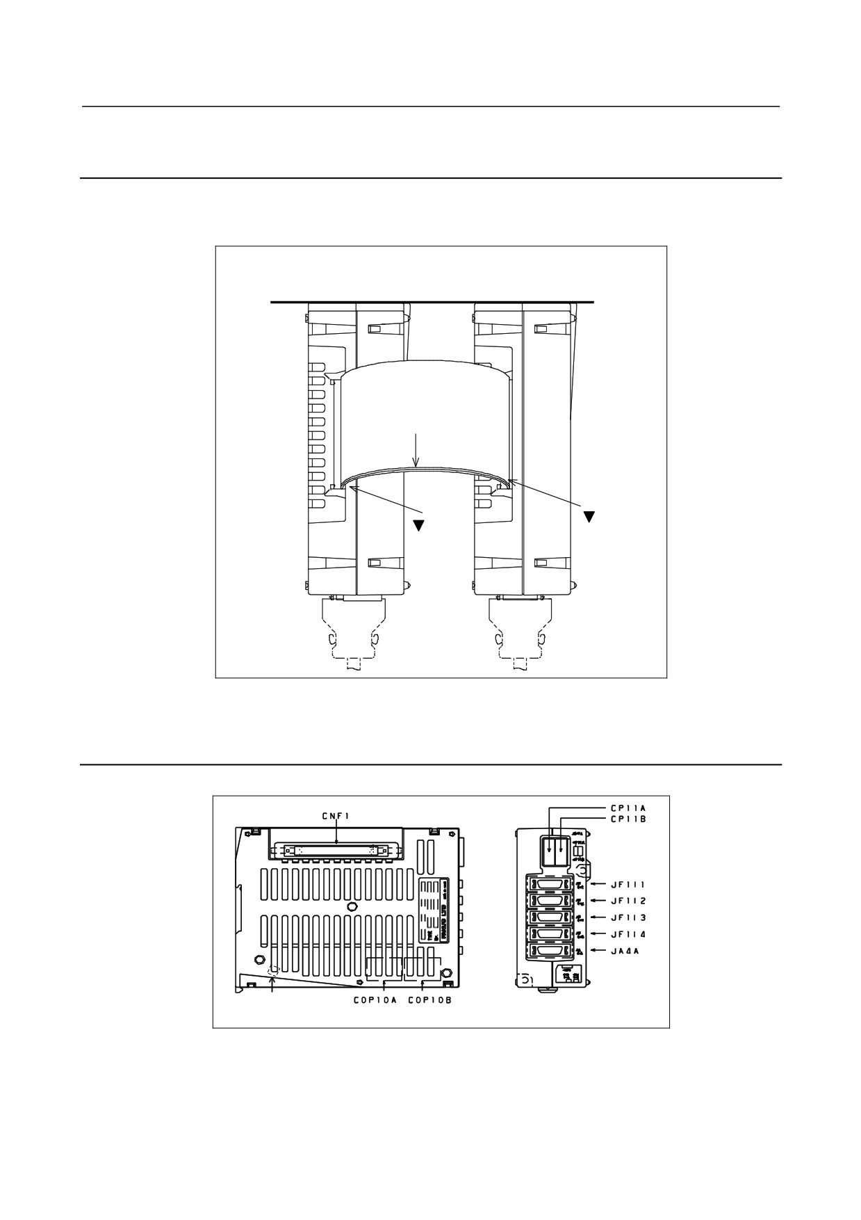
A flat cable is used to connect the analog input separate detector interface unit and additional unit as
shown below.
The flat cable is 100 mm long.
Units viewed from top
Analog input separate
Additional unit
detector interface unit
Mounting
surface
CNF1
CNF2
Marking
mark
mark
Place an order on a flat cable together with separate detector interface units.
7.3.8
Connector Locations
Connector locations on the analog input separate detector interface unit
GND
For the outside dimensions, see Appendix A.
- 109 -
7.SERVO INTERFACE
B-64303EN/03
7.3.9
Installation
1)
Notes on installation
(1) Use an interface unit in a completely enclosed cabinet.
(2) Install an interface unit on a vertical surface, and provide a space of 100 mm above and below
the unit. Below an interface unit, do not place equipment that generates a large amount of
heat.
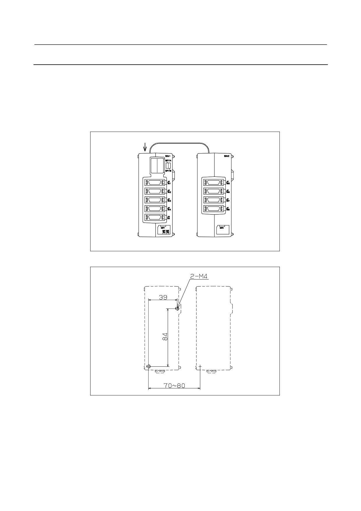
(3) When using an analog input separate detector interface unit and addition unit, place the units as
shown below so that the flat cable connecting the units does not block the vent holes. A flat
cable not longer than 100 mm must be used.
Vent holes
Flat cable
Basic unit
Additional unit
2)
Installation using screws
Analog input separate
detector interface unit
Additional unit
When using both an analog input separate detector interface unit and additional unit, install the units as
shown above, with the mounting holes horizontally separated by 70 to 80 mm.
- 110 -
B-64303EN/03
7.SERVO INTERFACE
7.3.10 Notes on Installing an Analog Input Separate Detector
Interface Unit
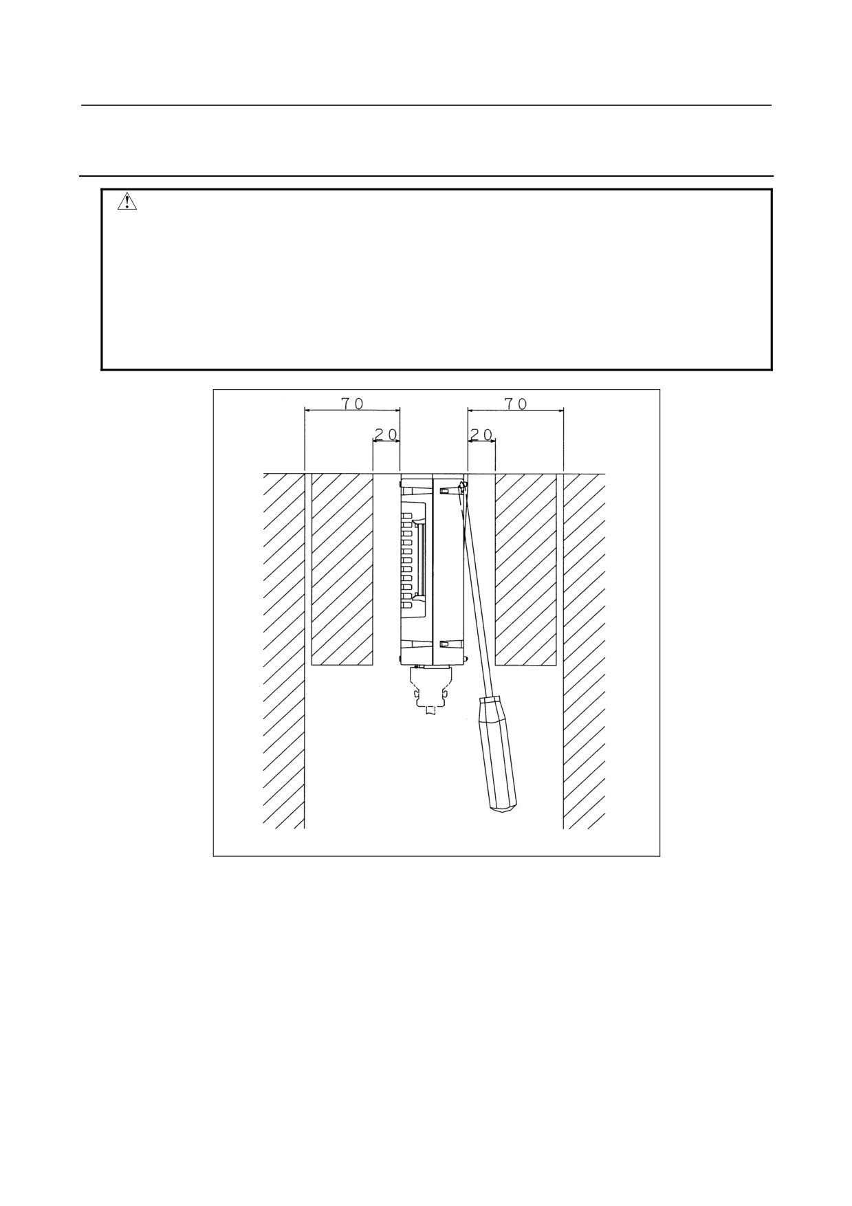
CAUTION
To install/remove the unit, a screwdriver must be inserted obliquely. So,
sufficient access clearances are required on both sides of the unit. As a
guideline, if the front of an adjacent unit appears flush with the unit or slightly set
back, allow a clearance of about 20 mm between the unit and the adjacent unit.
If the front of an adjacent unit protrudes beyond the front of the unit, allow a
clearance of about 70 mm between the unit and the adjacent unit. Also, when
installing the unit near a side of the cabinet, allow a clearance of about 70 mm
between the unit and the side of the cabinet.
Access clearance near an analog input separate detector interface unit
- 111 -
7.SERVO INTERFACE
B-64303EN/03
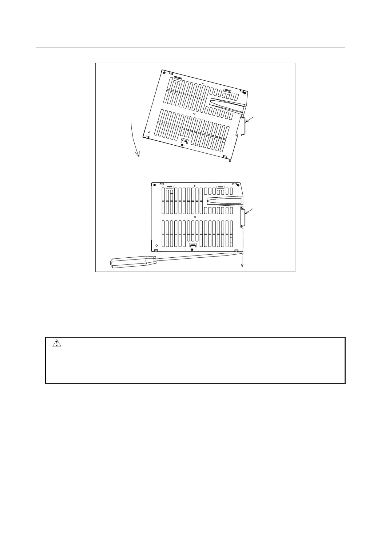
Installing the unit on the DIN rail
Installing the unit on
the DIN rail
DIN rail
Removing the unit
from the DIN rail
DIN rail
Installing the unit:
1.
Hook the unit on the top of the DIN rail.
2.
Push the unit in until it clicks.
Removing the unit:
1.
Push down the lock by using a screwdriver.
2.
Remove the unit by pulling the lower end of the unit towards you.
CAUTION
When removing the unit, be careful not to damage the lock by applying
excessive force. When installing and removing the unit, hold the upper and
lower ends of the unit so that stress is not applied to the side (that surface with
the slits) of the unit.
- 112 -
B-64303EN/03
8.CONNECTION TO FANUC I/O Link
8 CONNECTION TO FANUC I/O Link
WARNING
There is a possibility that I/O Link slave module will not operate normally due to
a failure of CNC or I/O module, or abnormally power supply voltage. To prevent
accidents even in this case, design the machine to operate safely by making a
safety circuit outside the I/O Link slave module.
8.1
OVERVIEW
FANUC I/O Link is a serial interface that has a CNC, a cell controller, various I/O units, the machine
operator's panel, or the Power Mate connected and receives or sends I/O signals (bit data) at high speed
between the devices. The FANUC I/O Link regards one device as the master and other devices as slaves
when more than one device is connected. Input signals from the slaves are sent to the master at specified
intervals. Output signals from the master are also sent to the slaves at specified intervals.
8.2
CONNECTION
The I/O Link interface connector JD51A is provided on the main board.
In the I/O there are the master station and its slave stations. The master is the control unit of the CNC,
and the slave is the I/O unit-A. The slaves are divided into groups, and up to 16 groups can be
connected to one I/O Link. (For the Series 0i Mate, however, the number of I/O points are limited.)
The I/O Link is connected in different ways depending on the types of units actually used and the I/O
points. To connect the I/O Link, the assignment and addresses of the I/O signals have been made
programmable with the PMC program. The total number of I/O points for each channel of I/O Link is
1024 or less.
There are two I/O Link connectors: JD1A and JD1B. These connectors are provided for all units that have
the I/O Link function. A cable must be connected from JD1A to JD1B. Although JD1A of the last unit
is not used and left open, it need not be connected with a terminator.
The pin assignments of connectors JD1A and JD1B are common to all units on the I/O Link, and are
illustrated on Subsec. 8.2.1. Use the figures when connecting the I/O Link irrespective of the type of
unit.
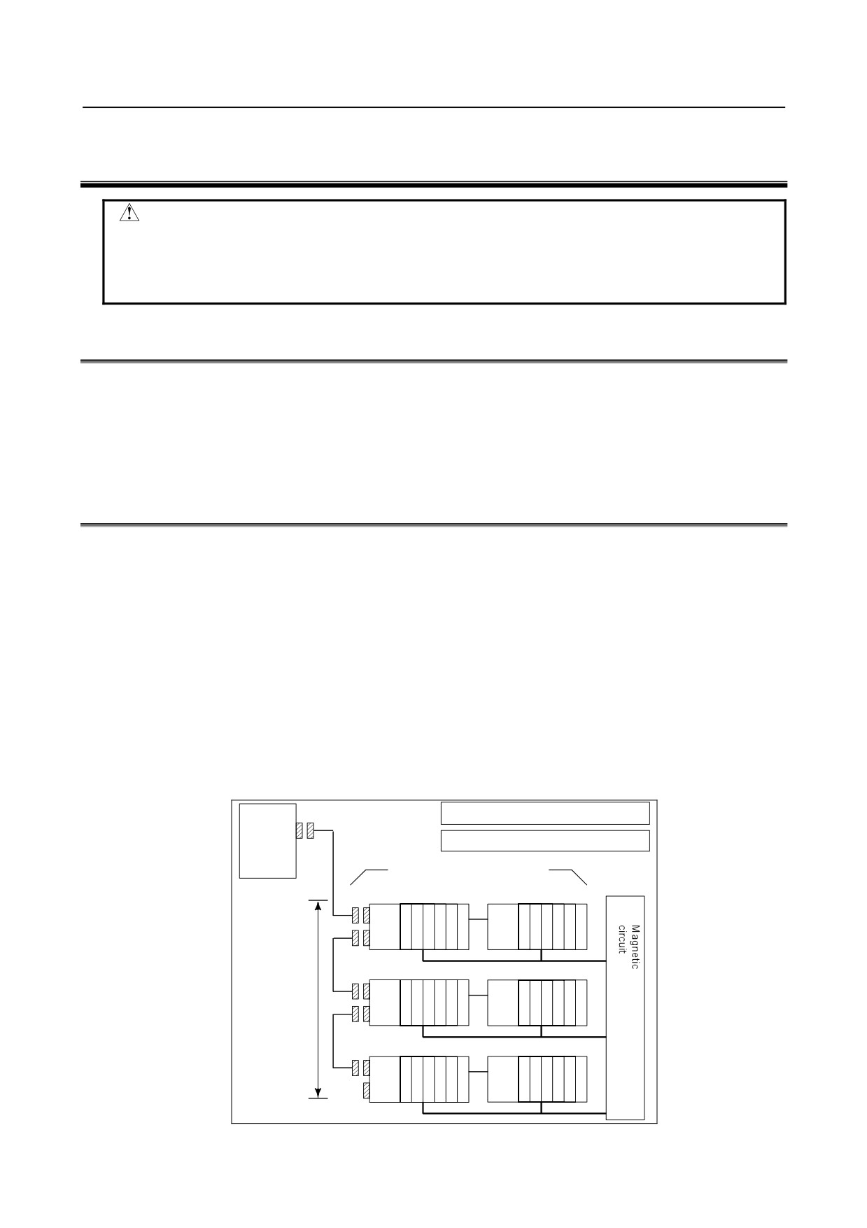
Control unit
I/O256/256 or less per group
JD51A
FANUC I/O Link
I/O1024/1024 or less per channel
FANUC I/O Unit-A × 2max
Control unit
Base unit 1
Base unit 2
JD1B
JD1A
Max.
16 group
JD1B
JD1A
:
JD1B
JD1A
Fig. 8.2 I/O Link connection diagram
- 113 -
8.CONNECTION TO FANUC I/O Link
B-64303EN/03
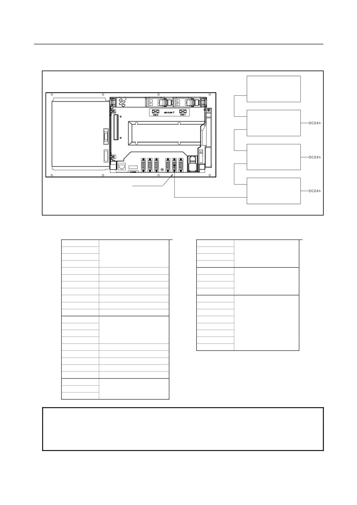
Example of I/O Link connection of the Series 0i Mate
I/O Link βi servo
0i Mate-D control unit
(See Section 9.8.)
Machine operator’s
panel
(See Section 9.9.)
Rear of unit
Operator’s panel I/O module
(DI;48 points, DO;32 points)
(with an M.P.G.)
(See Section 9.4.)
I/O Link connector
[JD51A]
Operator’s panel I/O module
(DI;48 points, DO;32 points)
(without an M.P.G.)
(See Section 9.4.)
M.P.G. : Manual Pulse Generator
The following example assumes that two operator's panel I/Os and one machine operator's panel are used.
DI space map
DO space map
X4
Operator’s panel I/O
Y0
Operator’s panel I/O
X5
48 DI points
Y1
32 DO points
:
Y2
X9
Y3
X10
Reserved
Y4
Operator’s panel I/O
:
Reserved
Y5
32 DO points
X15
Reserved
Y6
X16
1st MPG
Y7
X17
2nd MPG
Y8
Machine operator’s panel
X18
3rd MPG
Y9
X19
DO alarm detection
Y10
X20
Operator’s panel I/O
Y11
X21
48 DI points
Y12
:
Y13
X25
Y14
X26
Reserved
Y15
:
Reserved
:
Reserved
X34
Reserved
X35
DO alarm detection
X36
Machine operator’s panel
:
X47
NOTE
1 The manual pulse generators in X16 to X18 are directly read by the CNC, so
only the above allocation must be performed by the PMC.
2 For DO alarm detection in X19 and X35, see Subsection 9.4.9.
3 For the Series 0i Mate, up to 256 DI points and up to 256 Do points can be used.
- 114 -
B-64303EN/03
8.CONNECTION TO FANUC I/O Link
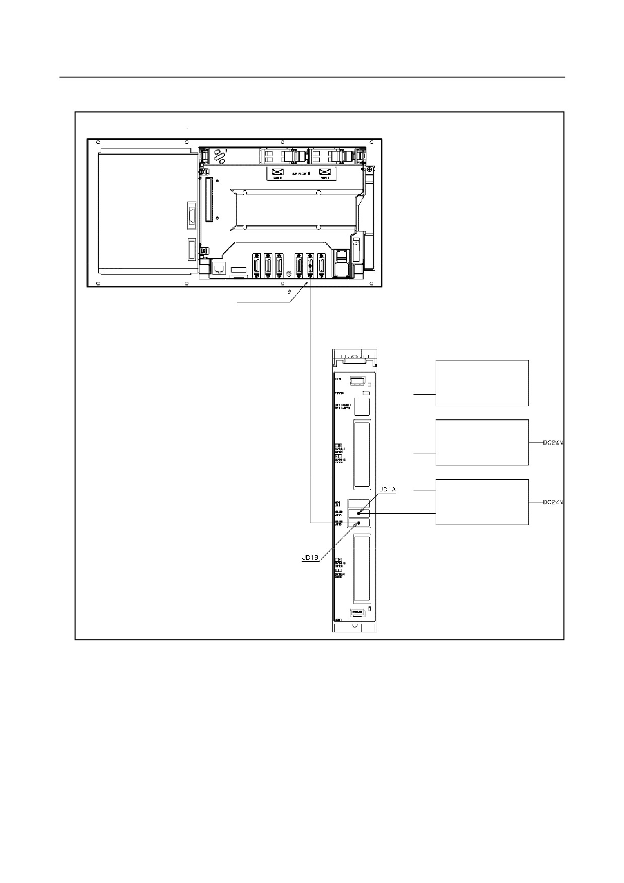
Example of I/O Link connection of the Series 0i
0i-D control unit
Rear of unit
I/O Link connector
[JD51A]
I/O unit for 0i
I/O Link βi servo
(See Section 9.8.)
Other units with the I/O
Link interface
Machine operator’s
panel
(See Section 9.9.)
- 115 -
8.CONNECTION TO FANUC I/O Link
B-64303EN/03
DI space map
DO space map
X0
I/O Unit for 0i-D
Y0
I/O Unit for 0i-D
X1
96 DI points
Y1
64 DO points
X2
Y2
X3
Y3
X4
Y4
X5
Y5
X6
Y6
X7
Y7
X8
Y8
Machine operator’s panel,
X9
Y9
other I/O
X10
Y10
X11
Y11
X12
I/O Unit for 0i-D: 1st MPG
Y12
X13
I/O Unit for 0i-D: 2nd MPG
Y13
X14
I/O Unit for 0i-D: 3rd MPG
Y14
X15
I/O Unit for 0i-D: DO alarm
Y15
detection
X16
Machine operator’s panel,
Y16
X17
other I/O
Y17
X18
Y18
X19
Y19
X20
Y20
・
・
・
・
・
・
NOTE
1 The manual pulse generators in X12 to X14 are directly read by the CNC, so
only the above allocation must be performed by the PMC.
2 For DO alarm detection in X15, see Section 9.6.
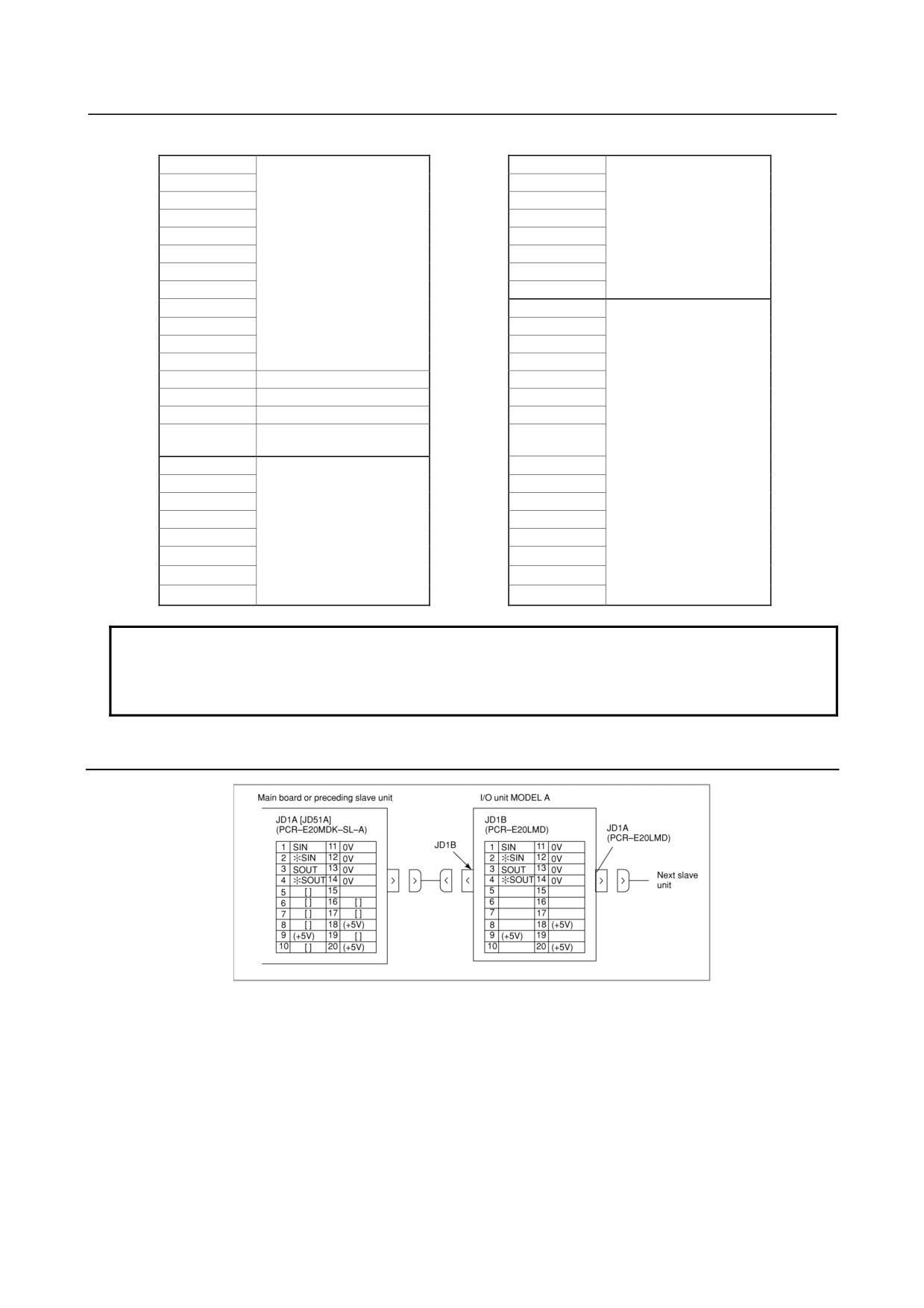
8.2.1
Connection of FANUC I/O Link by Electric Cable
+5 V terminals are for an optical I/O Link adapter. They are not necessary when connecting with a
metal cable.
A line for the +5V terminal is not required when the Optical I/O Link Adapter is not used.
No connections must be made to the pins with brackets ([ ]) because they are used in JD51A when the
second channels are connected in the FANUC I/O Link.
Do not make a connection to a pin for which no signal is assigned.
- 116 -
B-64303EN/03
8.CONNECTION TO FANUC I/O Link
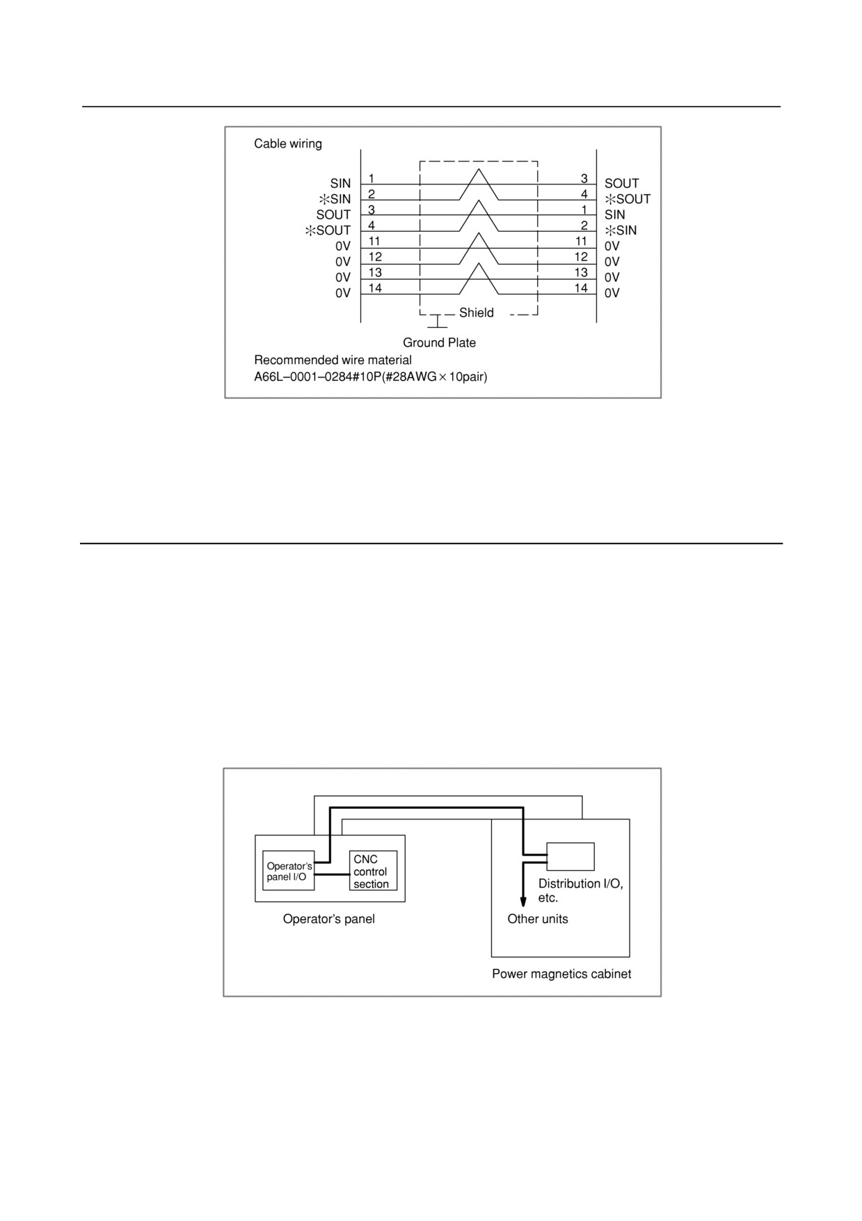
Recommended cable connectors
PCR-E20FA (Honda Tsushin Kogyo Co., Ltd.)
FCN-247J020-G/E (Fujitsu Ltd.)
52622-2011 (Molex Japan Co., Ltd.)
8.2.2
Connection of FANUC I/O Link by Optical Fiber Cable
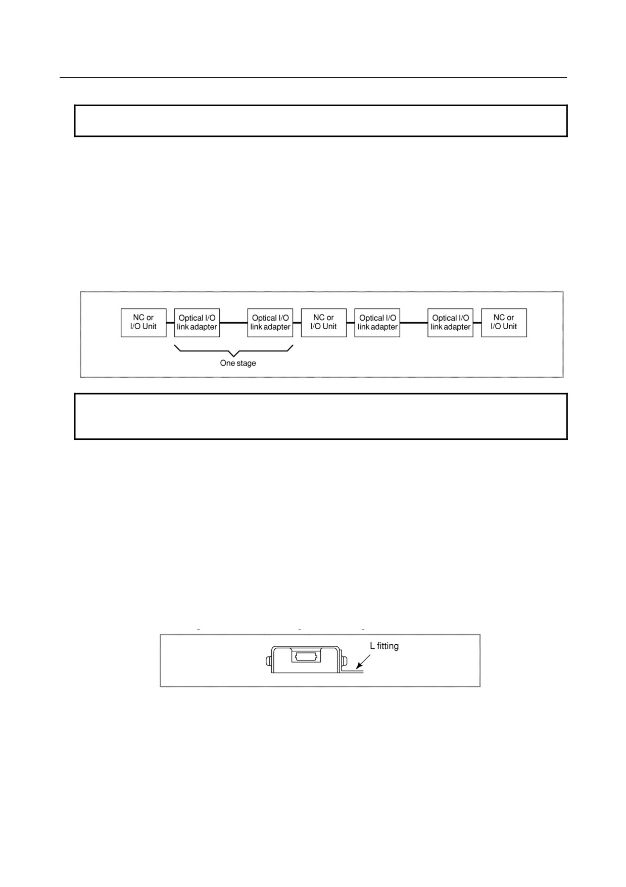
The FANUC I/O Link can be extended to the maximum length of 200 m with optical fiber cables using an
optical I/O Link adapter. The length of the electrical cable connected to the optical conversion adapter
must not exceed 2 m.
In the following cases, use an optical fiber cable.
• When the cable is more than 10 meters long. When the cable is more than 15 meters long if it is
laid within the same cabinet.
• When the cable is run between different cabinets, and the cabinets cannot be connected with each
other via a ground wire of 5.5 mm2 or more.
If the power magnetics cabinet includes an I/O Link slave unit, and cables are connected through a
duct to the operator's panel (as shown below), the control section I/O Link slave unit can be assumed
to be incorporated in the same cabinet.
• When there is concern that the cable is influenced by strong noise; for example :When there is a
strong electromagnetic noise source beside the cable such as a welding machine.
When a noise generating cable such as a power cable runs for a long distance in parallel with the
cable.
- 117 -
8.CONNECTION TO FANUC I/O Link
B-64303EN/03
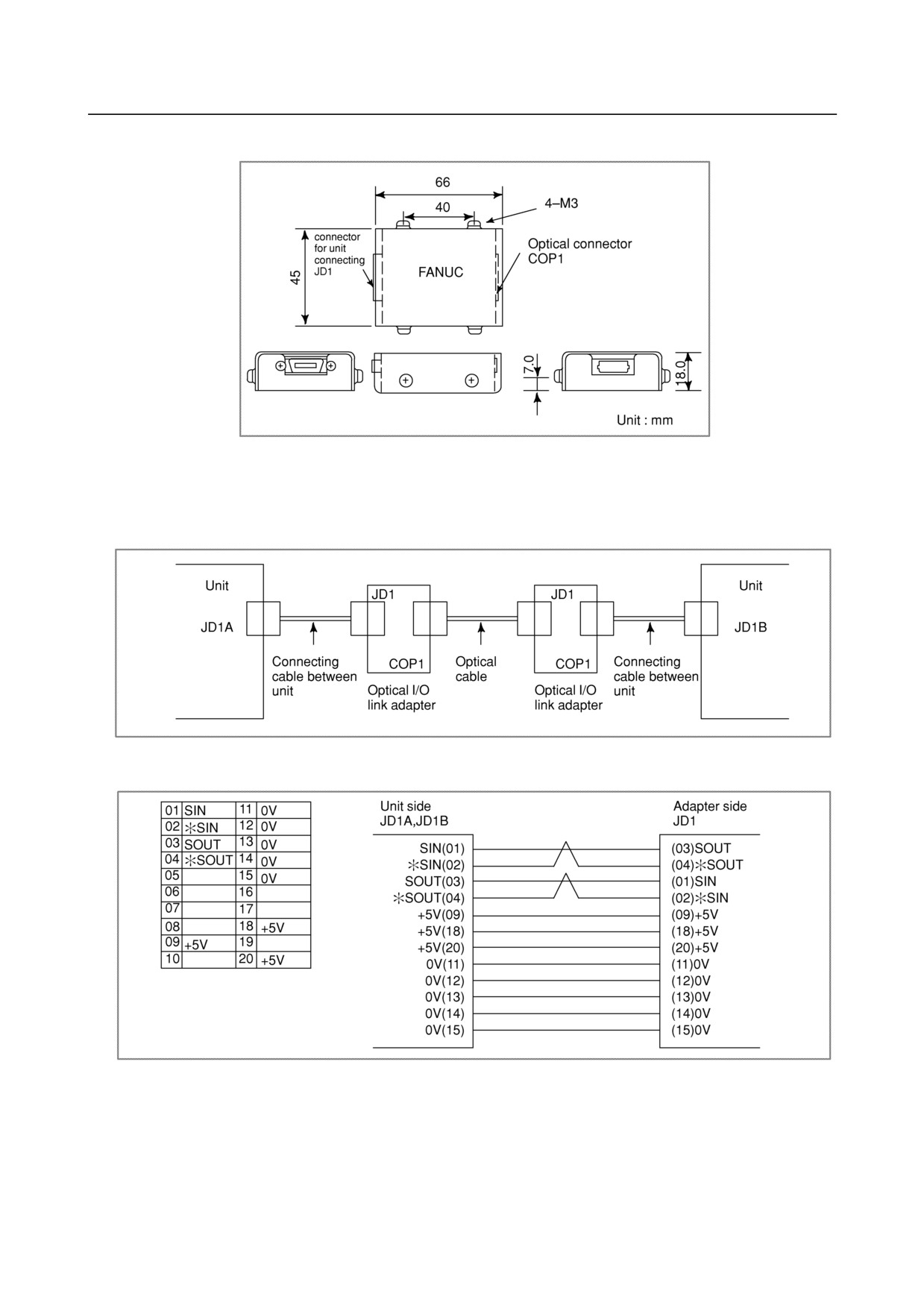
External dimension of optical link adapter
Weight of optical link adapter
Main body: Approx. 100 g.
-
Connection
-
Connection diagram
1
Recommended cable connectors
PCR-E20FA (Honda Tsushin Kogyo Co., Ltd.)
FCN-247J020-G/E (Fujitsu Ltd.)
52622-2011 (Molex Japan Co., Ltd.)
2
Recommended cable (wire material) : A66L-0001-0284#10P
3
Cable length : Max. 2 m (when the recommended cable is used)
- 118 -
B-64303EN/03
8.CONNECTION TO FANUC I/O Link
-
Optical cable
NOTE
For handling of optical cables, see Appendix D.
• Optical cable specification
A66L-6001-0026#L or later
For #L or later, specify the cable length. (See the Appendix D, “OPTICAL FIBER CABLE.”)
• Maximum number of connectable stages
Up to 16 high-speed type I/O link adapter stages can be connected in one I/O link, while only up to
five conventional I/O link adapters (standard type) can be connected.
1)
Standard type (A13B-0154-B001)
up to 5 adapter stages can be connected in series
2)
High-speed type (A13B-0154-B004)
up to 16 adapter stages can be connected in series
NOTE
It is impossible to use both high-speed and standard type adapters on the same
line.
• Power supply
The same power supply type can be used for both the standard type (A13B-0154-B001) and
high-speed type (A13B-0154-B004).
(a) Power supply voltage:
4.75 to 5.25 V (at receiving end)
(b) Required current:
200 mA
• Installation conditions
(a) The optical link adapter enclosure is not fully sealed ; install it with the CNC control unit in the
fully enclosed cabinet.
(b) Ground the case using the case fixing screw of the optical link adapter.
(c) The optical link adapter is light, and it may not be necessary to mount it with screws.
However, keep it from coming in contact with other circuits to prevent possible short-circuits.
When mounting the optical link adapter in a cabinet, attach it with an L-type fitting using the
case fixing screws (M3) of the optical link adapter.
• Required parts
(a) For making up an I/O Link using the optical link adapter, the following parts are necessary:
<1> Optical I/O Link adapter
2
<2> Interunit connecting cable
2
<3> Optical cable
1
• Relay with an optical fiber relay adapter
For the outline drawing of the optical fiber relay adapter, see Appendix D.
- 119 -
8.CONNECTION TO FANUC I/O Link
B-64303EN/03
NOTE
Optical fiber cables can be relayed only at are location.
When a high-speed optical link adapter is used, no optical fiber relay adapter can
be used.
• Maximum transmission distance with an optical fiber cable(s)
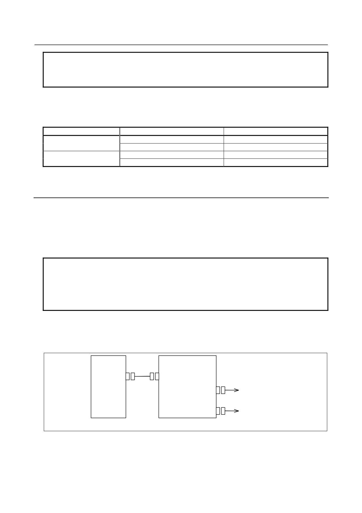
The table below shows the maximum transmission distance with an optical fiber cable(s), which
varies depending on whether a connection adapter is used for a relay.
Number of relay
Maximum transmission distance
0
200m
Standard type
1
100m (total)
0
100m
High-speed type
1
N/A
8.2.3
Connection when Multiple Channels of FANUC I/O Links are
Used
For the Series 0i, up to two channels of FANUC I/O Link interfaces can be used. This function can be
used to expand the number of I/O points to 2048/2048.
Signals for two channels are assigned to the FANUC I/O Link connector (JD51A) on the main board.
When using only one channel, see Subsection 8.2.1.
When using the second channel, use the I/O Link branching adapter for two channels to branch the
FANUC I/O Link.
NOTE
When Dual Check Safety is used in the Series 0i, up to three channels of
FANUC I/O Link interfaces can be used. However, the third channel can be
used only for connection of safety-related I/Os in Dual Check Safety. For
connection when using Dual Check Safety, refer to the FANUC Series
0i-MODEL D Dual Check Safety Connection Manual (B-64303EN-4).
Using the second channel
To use the second channel, use the I/O Link branching adapter to set a branch in the FANUC I/O Link.
Connection
CNC
I/O Link branching adapter
JD51A
JD44B
FANUC I/O Link channel 1
JD1A-1
FANUC I/O Link channel 2
JD1A-2
Connection after the I/O Link branching adapter is the same as that for the FANUC I/O Link.
Part number of the I/O Link branching adapter: A20B-1007-0680 (60 g)
- 120 -
B-64303EN/03
8.CONNECTION TO FANUC I/O Link
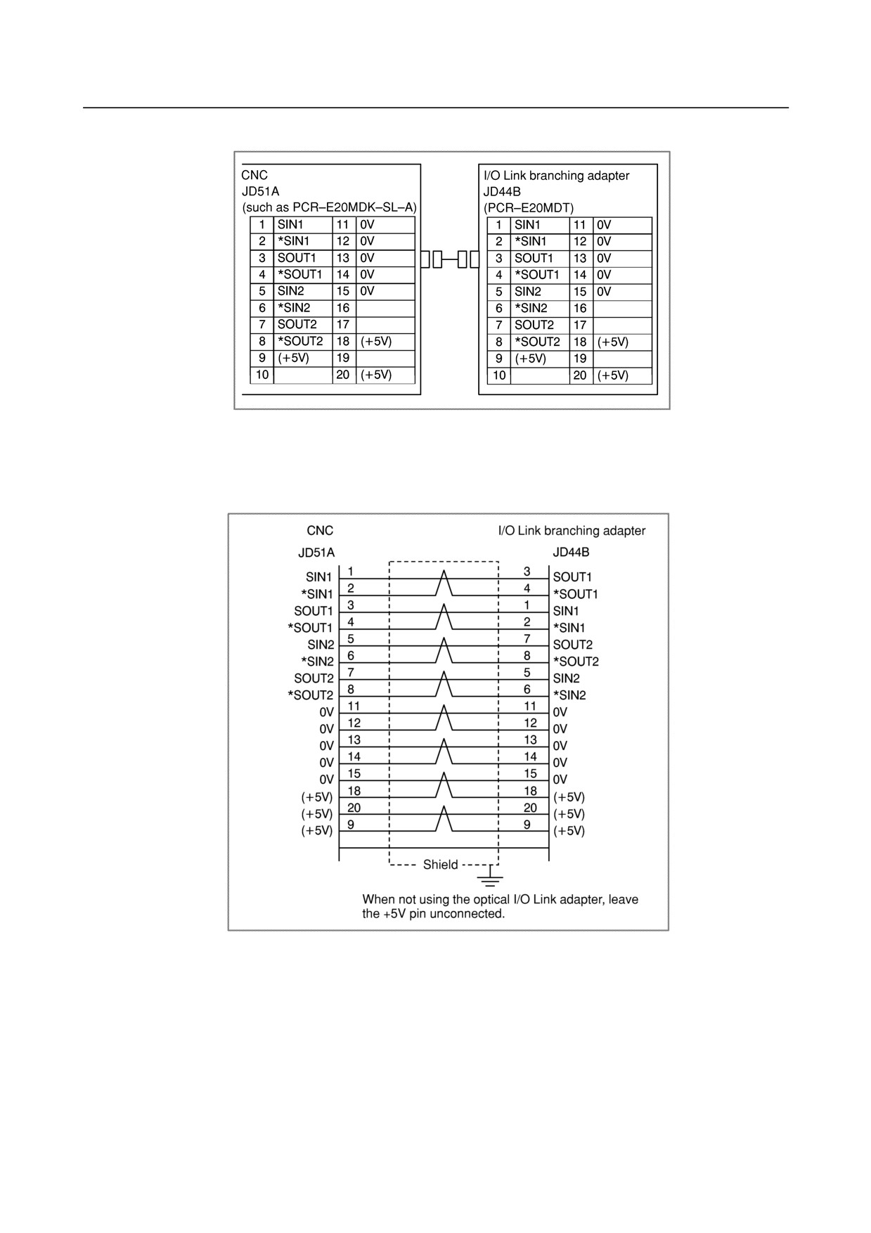
Connection between the CNC and I/O Link branching adapter
The +5V pin is provided to use the optical I/O Link adapter for optical fiber transmission. When not
using the optical I/O Link adapter, leave the +5V pin unconnected.
Cabling
Recommended cable connectors:
PCR-E20FA (Honda Tsushin Kogyo Co., Ltd.)
FI30-20S (Hirose Electric Co., Ltd.)
FCN-247J020-G/E (Fujitsu)
52622-2011 (Molex Japan Co., Ltd.)
Recommended cable: A66L-0001-0284#10P
Connection between the I/O Link branching adapter and slave I/O devices
The I/O Link branching adapter can be connected to slave I/O devices in the same way as for the
conventional FANUC I/O Link. See 8.2.1.
- 121 -
8.CONNECTION TO FANUC I/O Link
B-64303EN/03
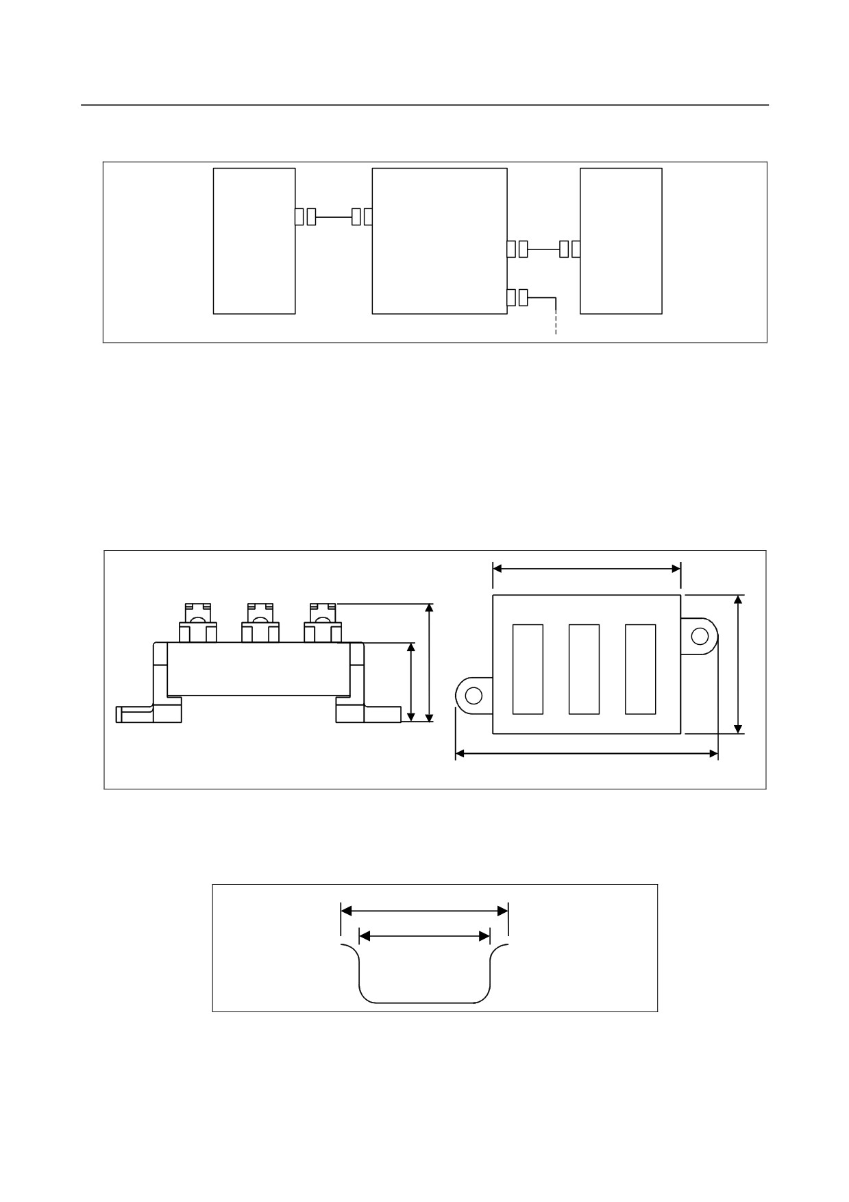
Cable length
CNC
I/O Link branching adapter
I/O device
lA
JD44A
JD44B
lB
JD1A-1
JD1B
JD1A-2
The total of lA and lB must not exceed 10 m; where lA is the length of the cable between connector JD44A
on the CNC and connector JD44B on the I/O Link branching adapter, and lB is the length of the cable
between connector JD1A-1 or JD1A-2 on the I/O Link branching adapter and connector JD1B on the I/O
unit. When all cables are accommodated in the same cabinet, however, a total cable length of up to 15
m is allowed.
Installation of the I/O Link branching adapter
Install the I/O Link branching adapter in a hermetically sealed cabinet like the CNC.
External dimensions of the I/O Link branching adapter
60
JD44B JD1A-1
JD1A-2
34
23
45
85
Unit : mm
Allow a clearance of about 10 cm above the adapter for connection and routing of cables.
Installation of the I/O Link branching adapter
1)
Installation on the DIN rail
35
25
Unit: mm
Recommended DIN rail
- 122 -
B-64303EN/03
8.CONNECTION TO FANUC I/O Link
2)
Screwing
11.6
2-M4
70
Unit: mm
Drilling on the plate
8.2.4
Power Supply Precautions
Take the following precautions about the power supply of a slave unit connected through the FANUC I/O
Link.
• During power-up, supply +24 V when or before turning on the CNC.
• When turning off a slave unit, be sure to turn off the other units connected through the same I/O
Link.
These are general rules. Therefore, when additional rules are specified for each unit, be sure to observe
them.
- 123 -
9.CONNECTION OF I/O Link SLAVE DEVICES
B-64303EN/03
9 CONNECTION OF I/O Link SLAVE
DEVICES
WARNING
There is a possibility that I/O Link slave module will not operate normally due to
a failure of CNC or I/O module, or abnormally power supply voltage. To prevent
accidents even in this case, design the machine to operate safely by making a
safety circuit outside the I/O Link slave module.
9.1
UNITS CONNECTABLE WITH THE FANUC I/O LINK
Basically, those units that have the slave interface of the FANUC I/O Link can be connected. The table
provides a list of general units that can be connected. A detailed description of each unit listed in the table
is provided later. For details of other units, refer to their manuals.
General units that are connectable
Unit name
General description
Reference
FANUC I/O Unit-MODEL A
I/O unit with a module configuration that can flexibly handle a
Connection and
combination of input/output signals required for the power
Maintenance
magnetics circuit
Manual
B-61813E
FANUC I/O Unit-MODEL B
I/O unit of distribution type that can flexibly handle a combination
Connection and
of input/output signals required for the power magnetics circuit
Maintenance
Manual
B-62163E
Handy Machine Operator’s
Small hand-held operator's panel that is operated on the machine
Connection
Panel
side and has a manual pulse generator, emergency stop switch,
Manual
enable switch, display unit, and input keys
B-63753EN
Distribution I/O
I/O unit of distribution type that can flexibly handle a combination
Section 9.2
Connector Panel I/O Module
of input/output signals required for the power magnetics circuit.
This unit has an interface with a manual pulse generator.
Distribution I/O
Unit that has an interface with the machine operator's panel. This
Section 9.3
Operator's Panel I/O Module
unit has an interface with a manual pulse generator.
(for Matrix Input)
Distribution I/O
Unit that has an interface with the machine operator's panel. This
Section 9.4
Operator's Panel I/O Module
unit can also handle input/output signals required for the power
magnetics circuit. This unit has an interface with a manual pulse
generator.
Distribution I/O
Unit that has an interface with the power magnetics cabinet. This
Section 9.4
Power Magnetics Cabinet I/O
unit can also handle input/output signals required for the power
Module
magnetics circuit.
Distribution I/O
I/O unit of distribution type that can flexibly handle a combination
Section 9.5
I/O Module Type-2 for
of input/output signals required for the power magnetics circuit.
Connector Panel
This unit has an interface with a manual pulse generator.
Connection Of I/O Units for 0i
As an I/O unit for a machine interface, an I/O unit for 0i that has a
Section 9.6
function equivalent to the function of the I/O card built into the
Series 0i-B can be used. The number of DI/DO points for 0i is
96/64.
Fanuc I/O Link Connection
Unit that makes a connection with a FANUC I/O Link master to
Section 9.7
Unit
transfer DI/DO signals
Connecting the Fanuc Servo
Unit that makes a connection with a CNC through the FANUC I/O
Section 9.8
Unit β Series With I/O Link
Link for servo motor control
- 124 -
B-64303EN/03
9.CONNECTION OF I/O Link SLAVE DEVICES
Unit name
General description
Reference
Connection To Standard
Standard machine operator's panel. This panel can be easily
Section 9.9
Machine Operator's Panel
customized.
Connection to the Small
Small machine operator's panel. The operator's panel has 30
Section 9.10
Machine Operator's Panel or
keys, an emergency stop switch, and two rotary switches for
Small Machine Operator's
override. Two types are available: small machine operator's panel
Panel B
and small machine operator's panel B.
Terminal Type I/O Module
I/O module that is equivalent to a connector panel I/O module.
Section 9.11
Input/output signals are connected on a spring-type terminal block
(ferrule terminal block).
I/O Link-As-I Converter
Converter unit that connects the FANUC I/O Link with the AS-i
Section 9.12
(Actuator Sensor Interface), which is an I/O-level open network
9.2
CONNECTION OF CONNECTOR PANEL I/O MODULE
9.2.1
Configuration
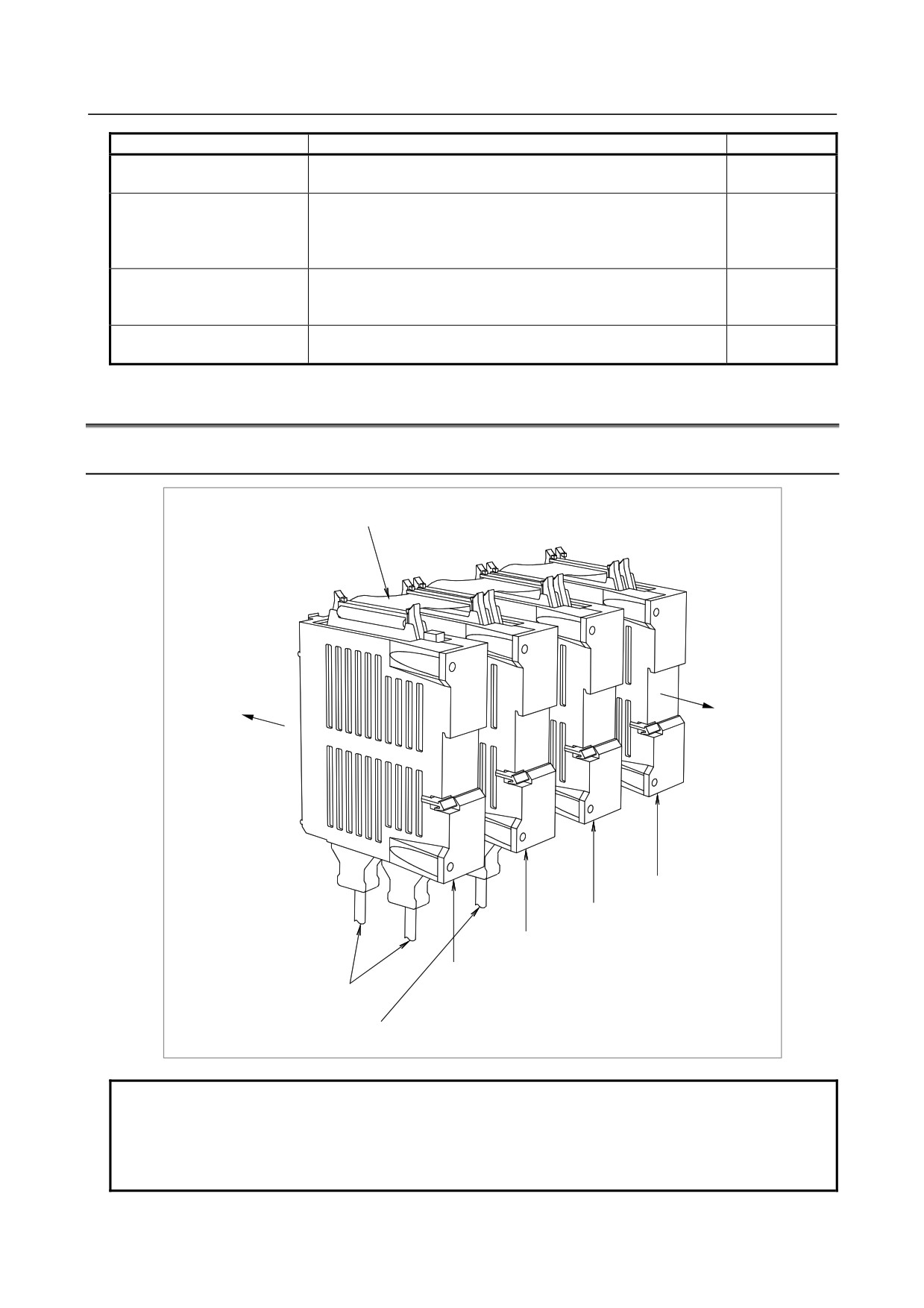
Flat cable for module connection
Direction to be
used when the
Direction to be used when
modules are
the modules are
mounted using
connected directly to the
DIN rails or
connection printed circuit
screws
board
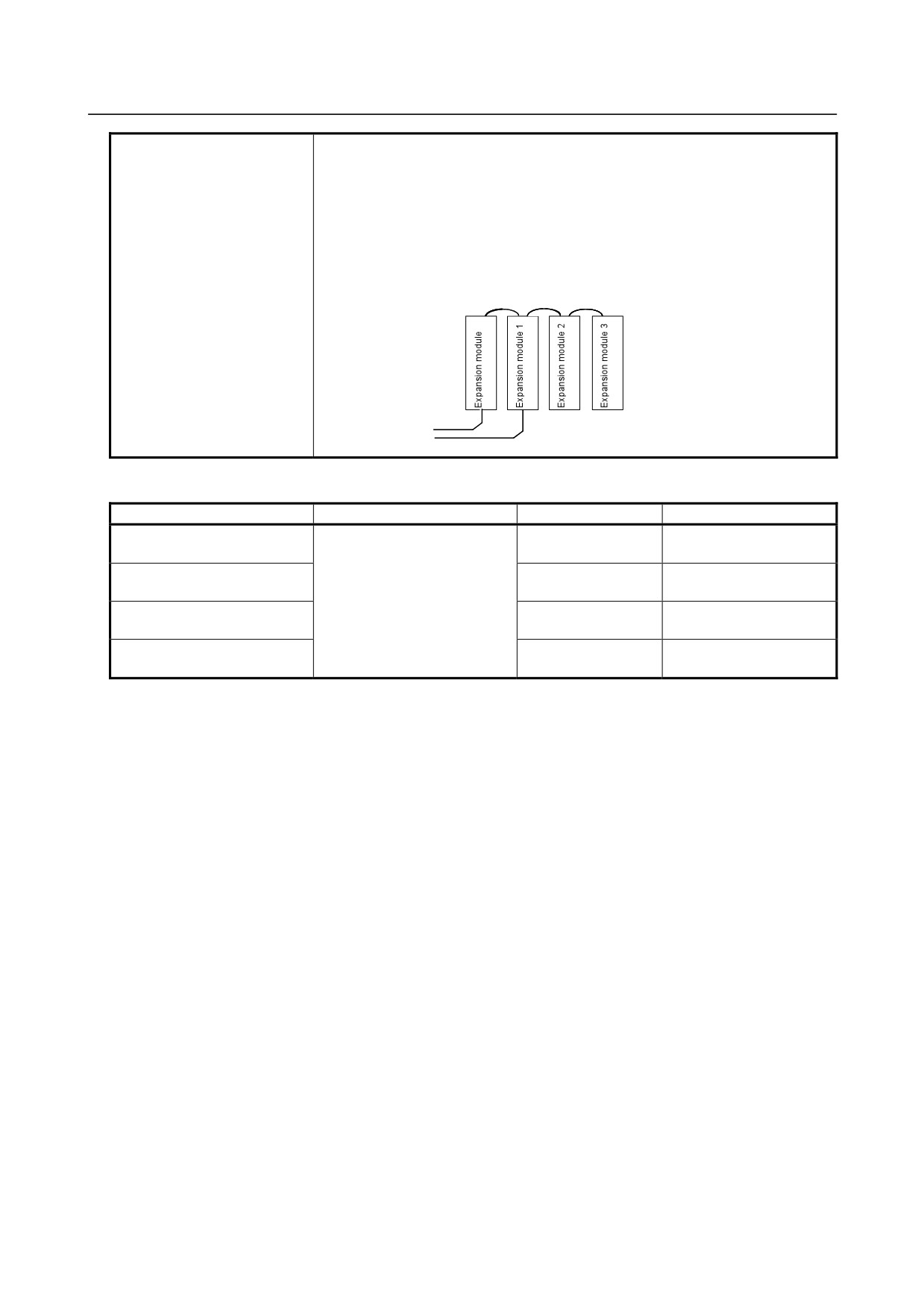
Expansion module 3
JD1A
JD1B
Expansion module 2
Expansion module 1
(with manual pulse generator)
Basic module
I/O Link cable
Manual pulse generator cable
NOTE
For direction connection to the connection printed circuit board, expansion
modules are installed to the right of the basic module on the installation plane.
For installation using DIN rails or screws, expansion modules are installed to the
left of the basic module on the installation plane.
- 125 -
9.CONNECTION OF I/O Link SLAVE DEVICES
B-64303EN/03
9.2.2
Connection Diagram
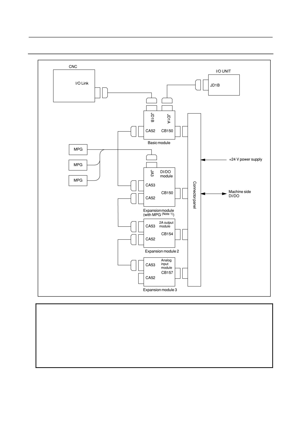
JD51A
NOTE
1 Ensure that the expansion module with the MPG interface is located nearest to
the basic module, as shown in the figure. When this module is used with other
units (such as I/O modules for the operator's panel) that are connected to the I/O
Link and have the MPG interface, only the MPG interface of the unit (module)
that is on the I/O Link and is nearest to the CNC is enabled.
2 The connection diagram above shows an example of using a DI/DO module, 2A
output module, and analog input module as expansion modules. These
expansion modules can be used in any combination.
- 126 -
B-64303EN/03
9.CONNECTION OF I/O Link SLAVE DEVICES
9.2.3
Module Specifications
Types of modules
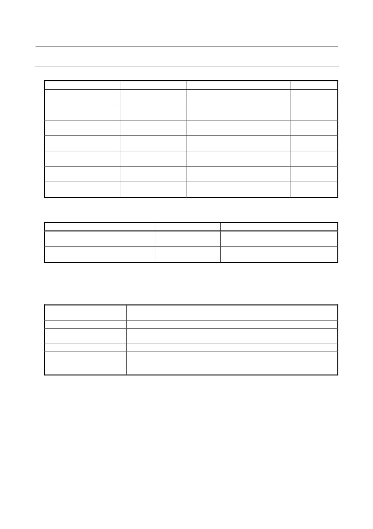
Name
Drawing No.
Specifications
Remarks
I/O module for connection
A03B-0815-C001
DI/DO : 24/16
(basic module)
I/O module for connection
DI/DO : 24/16
A03B-0815-C002
(expansion module A)
With MPG interface
I/O module for connection
DI/DO : 24/16
A03B-0815-C003
(expansion module B)
Without MPG interface
I/O module for connection
DO : 16
A03B-0815-C004
(expansion module C)
2A output module
I/O module for connection
A03B-0815-C005
Analog input module
NOTE 1
(expansion module D)
1A
Fuse (accessory)
A03B-0815-K002
(for basic module)
20 mm long
Inter-module flat cable
A03B-0815-K100
Suitable for a module interval of 32 mm
NOTE 1 It is possible to connect up to two Analog input modules to one Basic module.
Module specifications (common items)
Item
Specifications
Remarks
FANUC I/O Link
Expandable up to 16 units or 1024/1024
Interface with CNC
connection
points as CNC slaves
Interface between basic module and
Bus connection using a
Up to three expansion modules connectable
expansion modules
flat cable
per basic module
For the specifications (such as signal input requirements) specific to each module, see the relevant pages
of each item.
Installation conditions
Ambient temperature for the
Operation: 0°C to 55°C
unit
Storage and transportation: -20°C to 60°C
Temperature change
1.1°C/minute maximum
Humidity
Normal condition: 75% (relative humidity)
Short term (within one month): 95% (relative humidity)
Vibration
Operation: 0.5 G or less
Atmosphere
Normal machining factory environment (For use in an environment with relatively
high levels of dust, coolant, organic solutions, and so forth, additional measures
are required.)
- 127 -
9.CONNECTION OF I/O Link SLAVE DEVICES
B-64303EN/03
Other conditions
(1) Use each I/O module in a completely sealed cabinet.
(2) For ventilation within each I/O module, each module must be installed in the
orientation shown below.
Moreover, for ventilation and wiring, allow a clearance of 100 mm or more
above and below each module. Never place a device that generates a large
amount of heat below an I/O module.
(3) While referring to Subsection 9.2.7, ensure that the vent hole of the basic
module is not obstructed by the flat cable.
Upper side
I/O Link connection
Lower side
MPG connection
Power supply rating
Module
Power supply voltage
Power supply rating
Remarks
Basic module
24 VDC ±10% is fed through
0.2A+7.3mA×DI
Number of DI points with
the I/O connector (CB150) of
DI=ON
Expansion modules A and B
0.2A+7.3mA±DI the basic
0.1A+7.3mA×DI
Number of DI points with
module;
DI=ON
Expansion module C
±10% includes momentary
0.1A
(2A module)
variations and ripples.
Expansion module D
0.1A
(analog input module)
As a guideline for the heat dissipation, assume [power supply capacity × 24 (W)].
- 128 -
B-64303EN/03
9.CONNECTION OF I/O Link SLAVE DEVICES
9.2.4
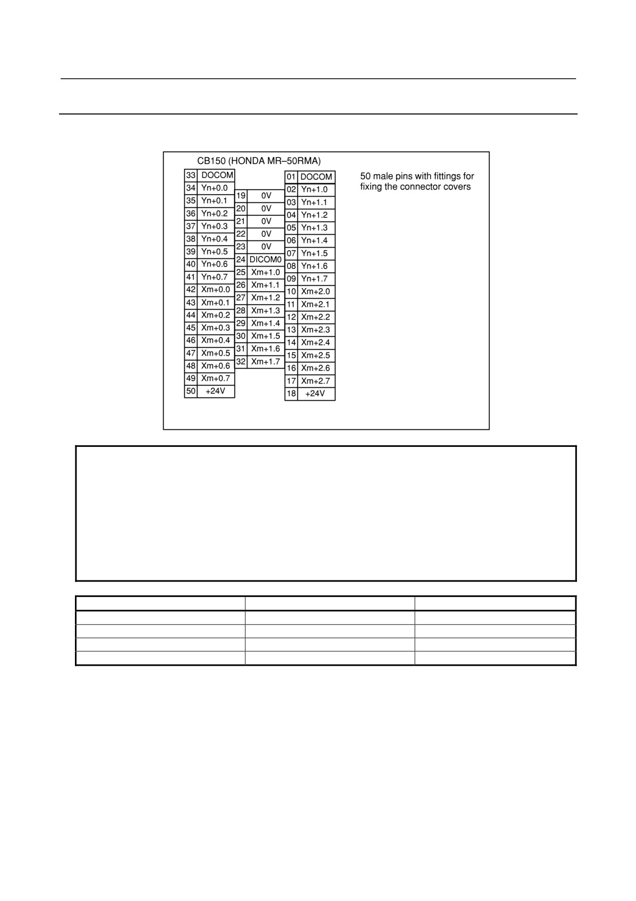
DI/DO Connector Pin Assignment
This section describes the DI/DO connector pin allocation of the basic module and expansion modules A
and B.
NOTE
1 The DI and DO addresses for the basic and expansion modules run
contiguously. These basic and expansion module DI and DO addresses are
allocated to the I/O Link as a group. For example, when the DI and DO top
addresses are X0004 and Y0000 (m = 4 and n = 0), respectively, then the
addresses are allocated as shown in the following table.
2 Pins 18 and 50 (+24V) of connector CB150 are used to apply 24 V externally to
a module. Be sure to connect these pins because the +24 V applied to the
module is used internally.
DI
DO
Basic module
X4 to X6
Y0 to Y1
Expansion module 1
X7 to X9
Y2 to Y3
Expansion module 2
X10 to X12
Y4 to Y5
Expansion module 3
X13 to X15
Y6 to Y7
- 129 -
9.CONNECTION OF I/O Link SLAVE DEVICES
B-64303EN/03
9.2.5
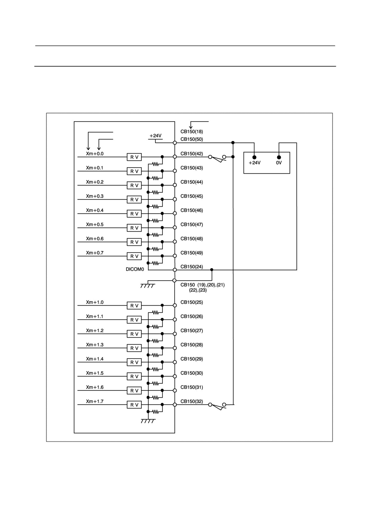
DI (Input Signal) Connection
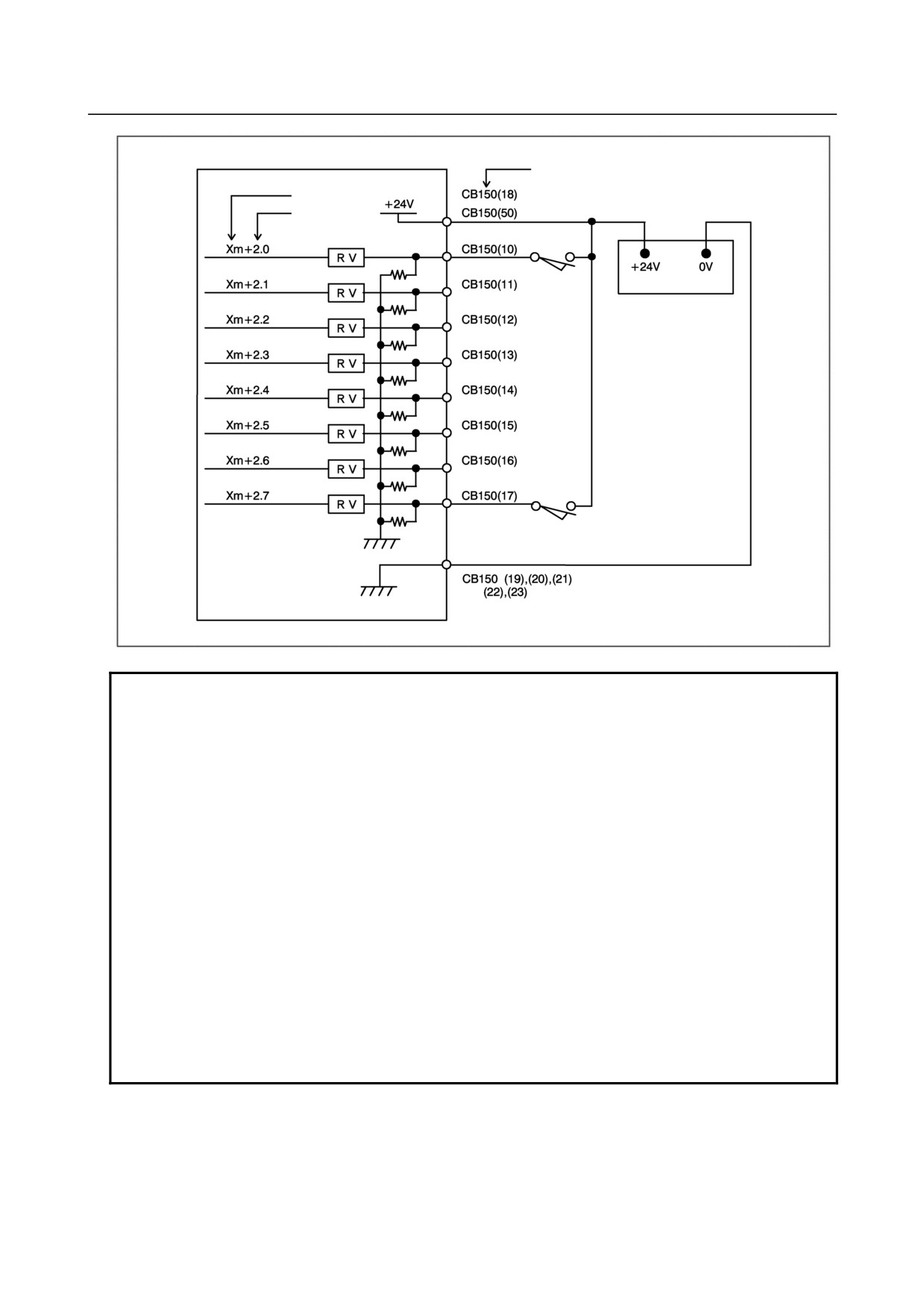
This section describes the DI (input signal) connections of the basic module and expansion modules A
and B.
• A maximum of 96 points are provided (24 points per module; 1 basic module + 3 expansion
modules).
Pin No.
Address No.
Bit No.
+24V stabilized power
supply
- 130 -
B-64303EN/03
9.CONNECTION OF I/O Link SLAVE DEVICES
Pin No.
Address No.
Bit No.
+24V stabilized power
supply
NOTE
Xm+0.0 through Xm+0.7 are DI pins for which a common voltage can be
selected. That is, by connecting the DICOM0 CB150(24) pin to the +24 V power
supply, a DI signal can be input with its logical state reversed. If, however, a
cable is connected to ground, it has the same effect as inputting an ON state DI
signal. To prevent such accidents, the connection of the DICOM0 CB150(24) pin
to the 0 V power supply is recommended whereever possible.
For safety reasons, the emergency stop signal needs to be allocated to an
appropriate bit of the addresses for which the common voltage is fixed, ranging
from Xm+1.0 to Xm+1.7 or from Xm+2.0 to Xm+2.7. See Subsection 8.4.19 for
information about how to allocate the emergency stop signal.
For unused DI pins allocated to the addresses for which the common voltage is
fixed (fromXm+1.0 to Xm+1.7 and from Xm+2.0 to Xm+2.7), the logic is fixed to
“0”. For unused pins allocated to Xm+0.0 to Xm+0.7 for which the common
voltage can be selected, the logic is fixed to “0” when the DICOM0 CB150(24)
pin is connected to the 0 V power supply. When the DICOM0 CB150(24) pin is
connected to the +24 V power supply, the logic is fixed to “1”. The logic of the
unused pins allocated to Xm+0.0 to Xm+0.7 is variable when the contact of the
DICOM0 CB150(24) pin is open.
- 131 -
9.CONNECTION OF I/O Link SLAVE DEVICES
B-64303EN/03
9.2.6
DO (Output Signal) Connection
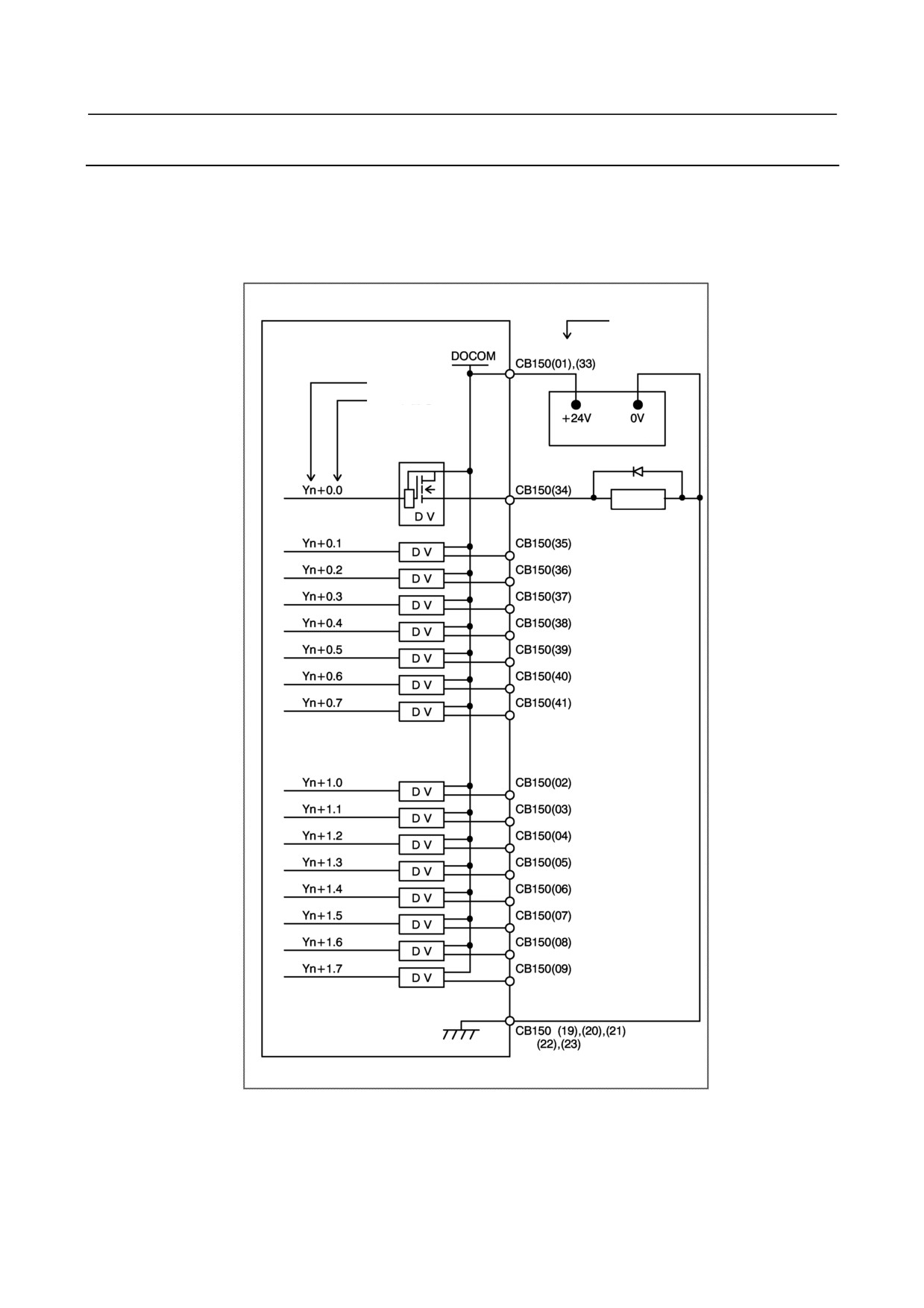
This section describes the DO (output signal) connections of the basic module and expansion modules A
and B.
• A maximum of 64 points are provided (16 points per module; 1 basic module + 3 expansion
modules).
Pin No.
Address No.
Bit No.
+24V stabilized power
supply
Relay
- 132 -
B-64303EN/03
9.CONNECTION OF I/O Link SLAVE DEVICES
9.2.7
DI/DO Signal Specifications
This section describes the specifications of the DI/DO signals used with the basic module and expansion
modules A and B.
DI (input signal specifications)
Number of points
24 points (per module)
Contact rating
30 VDC, 16 mA or more
Leakage current between
1 mA or less (26.4 V)
contacts when opened
Voltage decrease between
2 V or less (including a cable voltage decrease)
contacts when closed
Delay time
The receiver delay time is 2 ms (maximum). In addition, [I/O Link transfer time
between CNC and I/O module (2 ms maximum)] + [ladder scan period
(depending on CNC)] must be considered.
DO (output signal specifications)
Number of points
16 points (per module)
Maximum load current when ON
200 mA or less including momentary variations
Saturation voltage when ON
1 V (maximum) when the load current is 200 mA
Withstand voltage
24 V +20% or less including momentary variations
Leakage current when OFF
20 µA or less
Delay time
The driver delay time is 50 µs (maximum). In addition, [I/O Link transfer time
between CNC and I/O module (2 ms maximum)] + [ladder scan period
(depending on CNC)] needs to be considered.
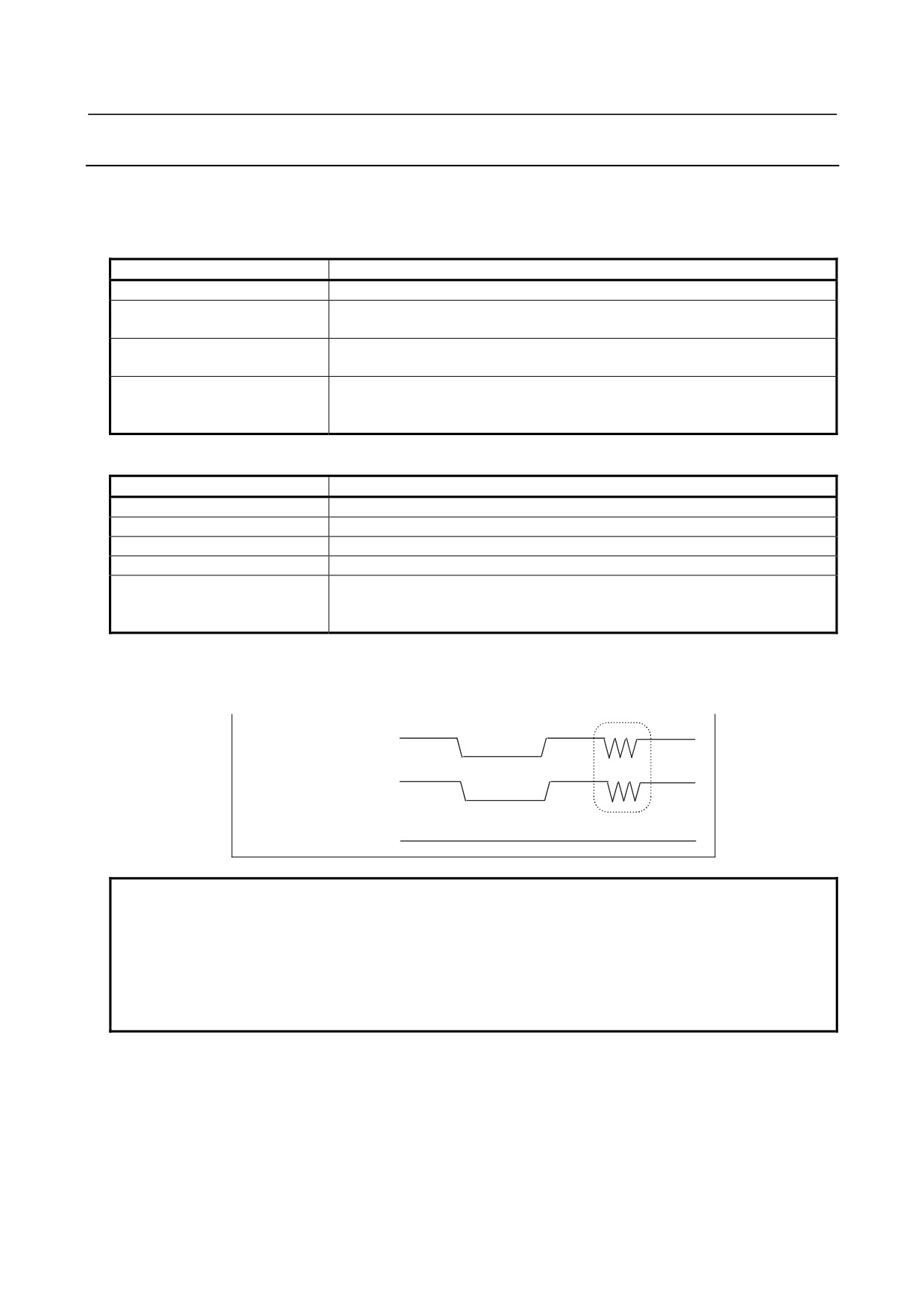
ON/OFF of the power supply (DO common) for DO signals (output signals)
By turning off (opening) the power supply pin (DOCOM) for the DO signals (output signals), all the DO
signals of each module can be turned off at the same time. At this time, the DO state is as shown below.
ON
DOCOM
OFF
DO state when DO is
ON
on in the sequence
OFF
DO state when DO is
ON
off in the sequence
OFF
NOTE
When DO is on in the sequence, the ON/OFF state of DOCOM is directly
reflected in the DO state as indicated above by the dashed box. The +24 V
signal to be supplied to the I/O module must not be turned off during operation.
Otherwise, a CNC communication alarm is issued. Ensure that +24 V is supplied
either when or before the power to the CNC is turned on, and that +24 V is
removed either when or after the power to the CNC is turned off.
Parallel DO (output signal) connection
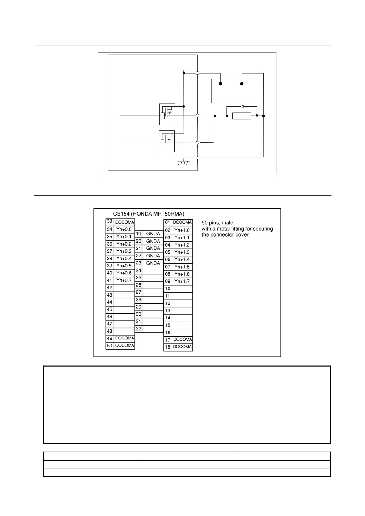
A DO load current of twice the level can be obtained by connecting DO points in parallel and exercising
ON/OFF control at the same time in the sequence. Namely, the maximum load current per DO point is
200 mA.
By connecting two DO points in parallel and turning on the two DO points at the same time, 400 mA can
be obtained. In this case, however, the leakage current is doubled up to 40 µA when the DO points are
turned off.
- 133 -
9.CONNECTION OF I/O Link SLAVE DEVICES
B-64303EN/03
DOCOM
CB150(01),(33)
+24V
0V
+24 V regulated
power supply
Relay
DV
DV
9.2.8
2A Output Connector Pin Allocation
This section describes the 2A output connector pin allocation of expansion module C.
NOTE
1 The DI/DO addresses of an expansion module and the DI/DO addresses of the
basic module are contiguous.
Addresses allocated to I/O Link are handled as a group covering the basic and
expansion modules. That is, when the first addresses allocated are X0004 and
Y0000 (m = 4, n = 0), the DI/DO addresses are as listed below.
2 When the 2A output module is used, the DI addresses of the module cannot be
used. (When the 2A output module is used as expansion module 3, X13 through
X15 cannot be used.)
DI
DO
Basic module
X4 to X6
Y0 to Y1
Basic module 1
X7 to X9
Y2 to Y3
- 134 -
B-64303EN/03
9.CONNECTION OF I/O Link SLAVE DEVICES
DI
DO
Basic module 2
X10 to X12
Y4 to Y5
Basic module 3
X13 to X15
Y6 to Y7
9.2.9
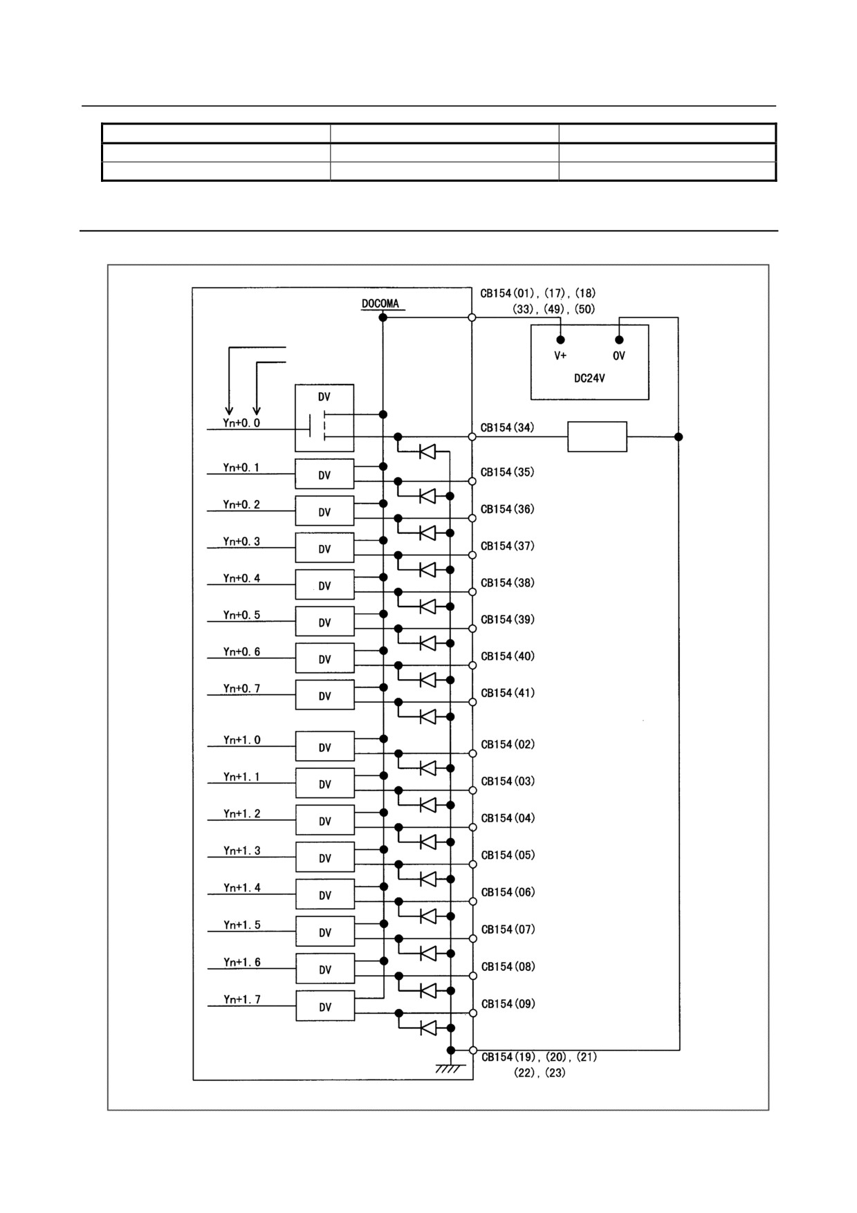
2A DO (Output Signal) Connection
This section describes the 2A output connector connections of expansion module C.
Address No.
Bit No.
Solenoid,
etc.
- 135 -
9.CONNECTION OF I/O Link SLAVE DEVICES
B-64303EN/03
9.2.10
2A Output DO Signal Specifications
This section describes the specifications of the 2A output DO signals used with expansion module C.
DO (output signal specifications)
Number of points
32 points (per module)
2 A or less per point.
Maximum load current when ON
12 A maximum for the entire module (DO: 16 points) (including momentary
variations).
24 V +20% or less
Withstand voltage
(including momentary variations)
Leakage current when OFF
100 µA or less
[I/O Link transfer time (2 ms maximum)] + [ladder scan period (depending on
Delay time
CNC)] must be considered.
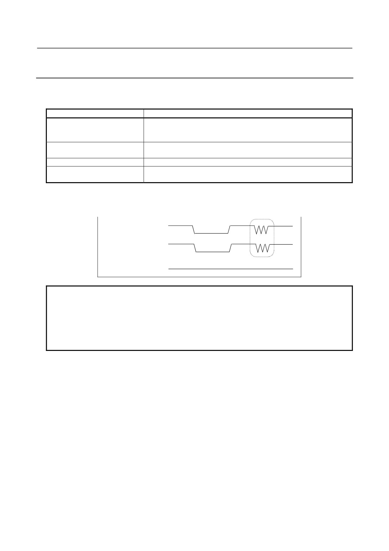
ON/OFF of the power supply (DO common) for DO signals (output signals)
By turning off (opening) the power supply pin (DOCOM) for the DO signals (output signals), all the DO
signals of each module can be turned off at one time. At this time, the DO state is as shown below.
ON
DOCOM
OFF
DO state when DO is
ON
on in the sequence
OFF
DO state when DO is
ON
off in the sequence
OFF
NOTE
When DO is on in the sequence, the ON/OFF state of DOCOM is directly
reflected in the DO state as indicated above by the dashed box. The +24 V
signal to be supplied to the I/O module must not be turned off during operation.
Otherwise, a CNC communication alarm is issued. Ensure that +24 V is supplied
either when or before the power to the CNC is turned on, and that +24 V is
removed either when or after the power to the CNC is turned off.
Parallel DO (output signal) connection
The 2A output module does not allow parallel DO connections including parallel connections with the
DO signals of other modules.
- 136 -