FANUC Series 0i-MODEL D, Series 0i Mate-MODEL D. CONNECTION MANUAL (HARDWARE) - page 4
B-64303EN/03
6.SPINDLE CONNECTION
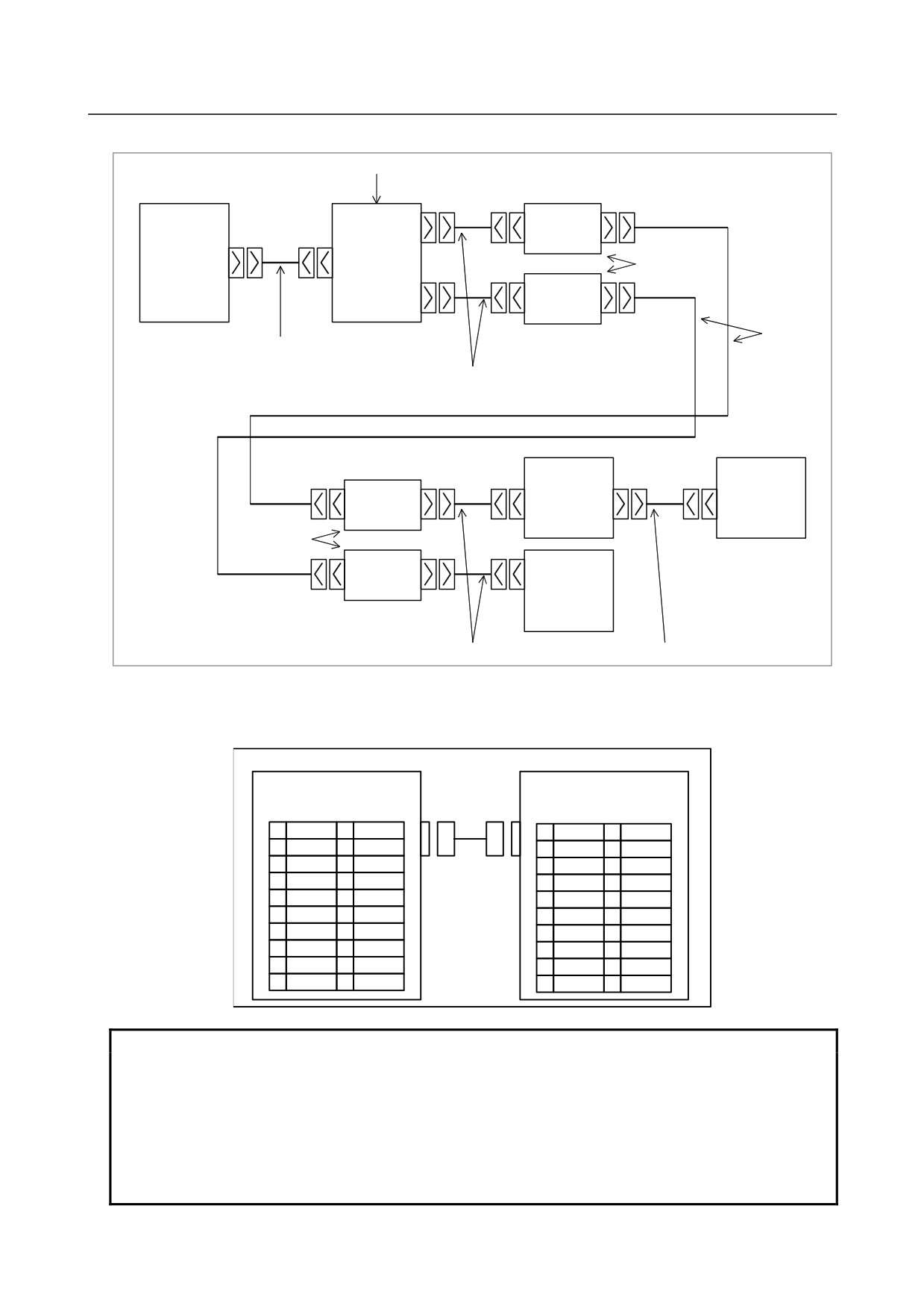
(Connection diagram when optical cables are used)
Serial spindle connector panel
CNC
JD1
JA7A-1
COP1
Optical adapter
JA48
JA41
JD1
JA7A-2
COP1
Interconnection cable 4
Optical cable
Interconnection cable 2
Spindle amplifier
Spindle amplifier
JD1
JA7B
JA7B
COP1
JA7A
JA7A
Optical adapter
JA7B
JD1
COP1
JA7A
Spindle amplifier
Interconnection cable 2
Interconnection cable 1
(Cable connections when only electrical cables are used)
Cable connection between the CNC and serial spindle connector panel
(Interconnection cable 3)
CNC
Serial spindle connector panel
JA41 (main board)
FI80-20P, DF1R020WB1
JA48
(PCR-EV20MDT)
PCR-E20MDT
1
SINA
11
1
SINA
11
2
*SINA
12
0V
2
*SINA
12
0V
3
SOUTA
13
3
SOUTA
13
4
*SOUTA
14
0V
4
*SOUTA
14
0V
5
< >
15
SINB
5
15
SOUTB
6
< >
16
0V
6
16
0V
7
< >
17
*SINB
7
17
*SOUTB
8
< >
18
(+5V)
8
18
(+5V)
9
(+5V)
19
SOUTB
9
(+5V)
19
SINB
10
*SOUTB
20
(+5V)
10
*SINB
20
(+5V)
NOTE
1 When an optical cable is used for the connection between the CNC and a
spindle, the +5V signals indicated in parentheses are used to feed power to the
optical adapter.
2 No connections must be made to the pins with angle brackets (< >) because
they are reserved for expansions.
3 The upper connector specification of JA41 is for the LCD-mounted type.
The lower connector specification in parentheses is for the stand-alone type.
- 77 -
6.SPINDLE CONNECTION
B-64303EN/03
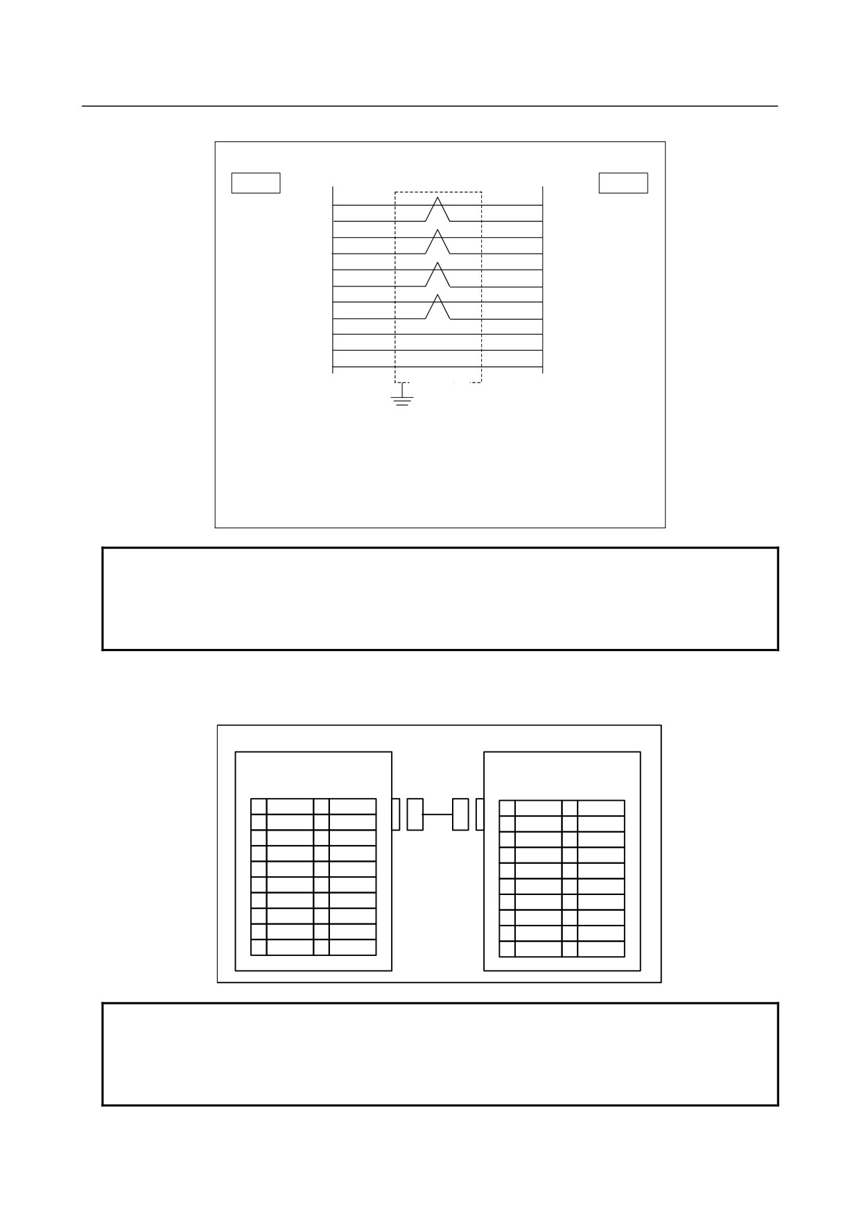
Cable connection
JA41
JA48
1
3
SINA
SOUTA
2
4
*SINA
*SOUTA
3
1
SOUTA
SINA
4
2
*SOUTA
*SINA
15
15
SINB
SOUTB
17
17
*SINB
*SOUTB
19
19
SOUTB
SINB
10
10
*SOUTB
*SINB
12
12
0V
0V
14
14
0V
0V
16
16
0V
0V
Shield
Ground plate
Recommended cable connector:
PCR-E20FA (manufactured by Honda Tsushin Kogyo)
FCN-247J020-G/E (manufactured by Fujitsu)
52622-2011 (manufactured by Molex Japan)
Recommended cable specification: A02B-0236-K845
Recommended wire specification: A66L-0001-0284#10P (#28AWG × 10 pairs)
NOTE
When this cable is installed close to other cables such as a power line, a
shielded wire must be connected to the ground plate. When the CNC is
installed close to the serial spindle connector panel, however, no connection to
the ground plate is necessary.
(Cable connections when optical cables are used)
Cable connection between the CNC and serial spindle connector panel
(Interconnection cable 4)
CNC
Serial spindle connector panel
JA41 (main board)
JA48
FI80-20P, DF1R020WB1
(PCR-EV20MDT)
PCR-E20MDT
1
SINA
11
1
SINA
11
2
*SINA
12
0V
2
*SINA
12
0V
3
SOUTA
13
3
SOUTA
13
4
*SOUTA
14
0V
4
*SOUTA
14
0V
5
< >
15
SINB
5
15
SOUTB
6
< >
16
0V
6
16
0V
7
< >
17
*SINB
7
17
*SOUTB
8
< >
18
+5V
8
18
+5V
9
+5V
19
SOUTB
9
+5V
19
SINB
10
*SOUTB
20
+5V
10
*SINB
20
+5V
NOTE
1 No connections must be made to the pins with angle brackets (< >) because
they are reserved for expansions.
2 The upper connector specification of JA41 is for the LCD-mounted type.
The lower connector name in parentheses is for the stand-alone type.
- 78 -
B-64303EN/03
6.SPINDLE CONNECTION
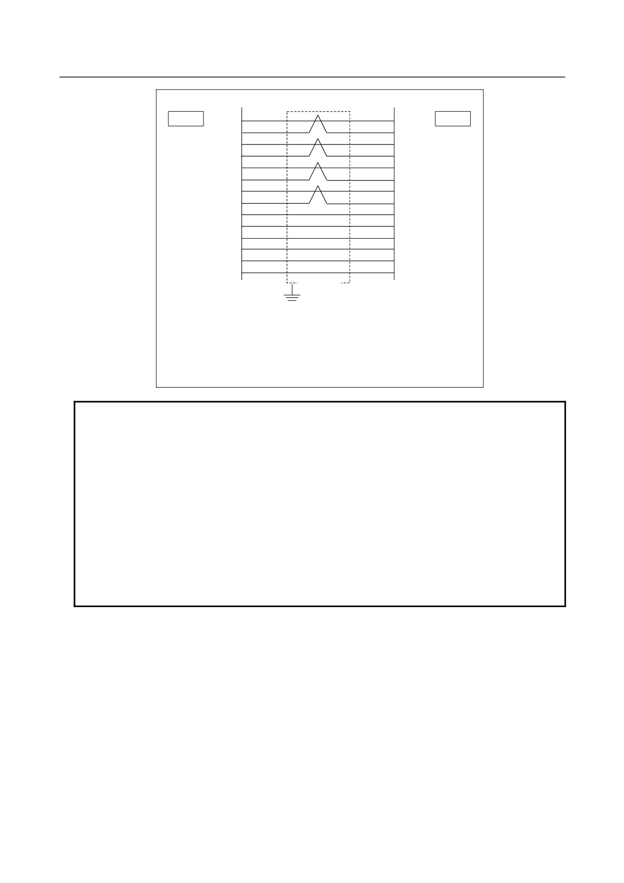
Cable connection
1
3
JA41
SINA
SOUTA
JA48
2
4
*SINA
*SOUTA
3
1
SOUTA
SINA
4
2
*SOUTA
*SINA
15
15
SINB
SOUTB
17
17
*SINB
*SOUTB
19
19
SOUTB
SINB
10
10
*SOUTB
*SINB
9
9
+5V
+5V
18
18
+5V
+5V
20
20
+5V
+5V
12
12
0V
0V
14
14
0V
0V
16
16
0V
0V
Shield
Ground plate
Recommended cable connector:
PCR-E20FA (manufactured by Honda Tsushin Kogyo)
FCN-247J020-G/E (manufactured by Fujitsu)
52622-2011 (manufactured by Molex Japan)
Recommended cable specification: A02B-0236-K847
Recommended wire specification: A66L-0001-0284#10P (28AWG × 10 pairs)
NOTE
1 When this cable is installed close to other cables such as a power line, a
shielded wire needs to be connected to the ground plate. When the CNC is
installed close to the serial spindle connector panel, however, a connection to
the ground plate is unnecessary.
2 Connection cable 1 between the serial spindle connector panel and the spindle
amplifier, and connection cable 2 between the serial spindle connector panel and
the optical module are the same as those used when one or two serial spindles
are connected.
3 When this cable is installed close to other cables such as a power line, a
shielded wire needs to be connected to the ground plate. However, when the
serial spindle connector panel is installed near the spindle amplifier or when the
serial spindle connector panel is installed near the optical module, no connection
to the ground plate is necessary.
- 79 -
6.SPINDLE CONNECTION
B-64303EN/03
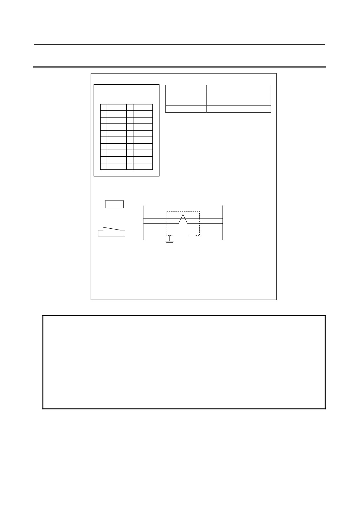
6.2
ANALOG SPINDLE
CNC
JA40 (main board)
Signal name
Description
FI80-20P, DF1R020WB1
SVC,ES
Spindle voltage command
(PCR-EV20MDT)
and common
1
(
)
11
(
)
ENB1,ENB2
Spindle enable
2
(0V)
12
3
(
)
13
(
)
4
14
5
ES
15
(
)
6
(
)
16
7
SVC
17
(
)
8
ENB1
18
9
ENB2
19
(
)
10
20
Cable connection
Analog spindle servo
unit or inverter
JA40
7
10
SVC
DA2
5
12
ES
E
8
14
ENB1
9
16
ENB2
Shield
Ground plate
Recommended cable connector:
PCR-E20FA (manufactured by Honda Tsushin Kogyo)
FCN-247J020-G/E (manufactured by Fujitsu)
52622-2011 (manufactured by Molex Japan)
Recommended wire specification: A66L-0001-0284#10P (28AWG × 10 pairs)
NOTE
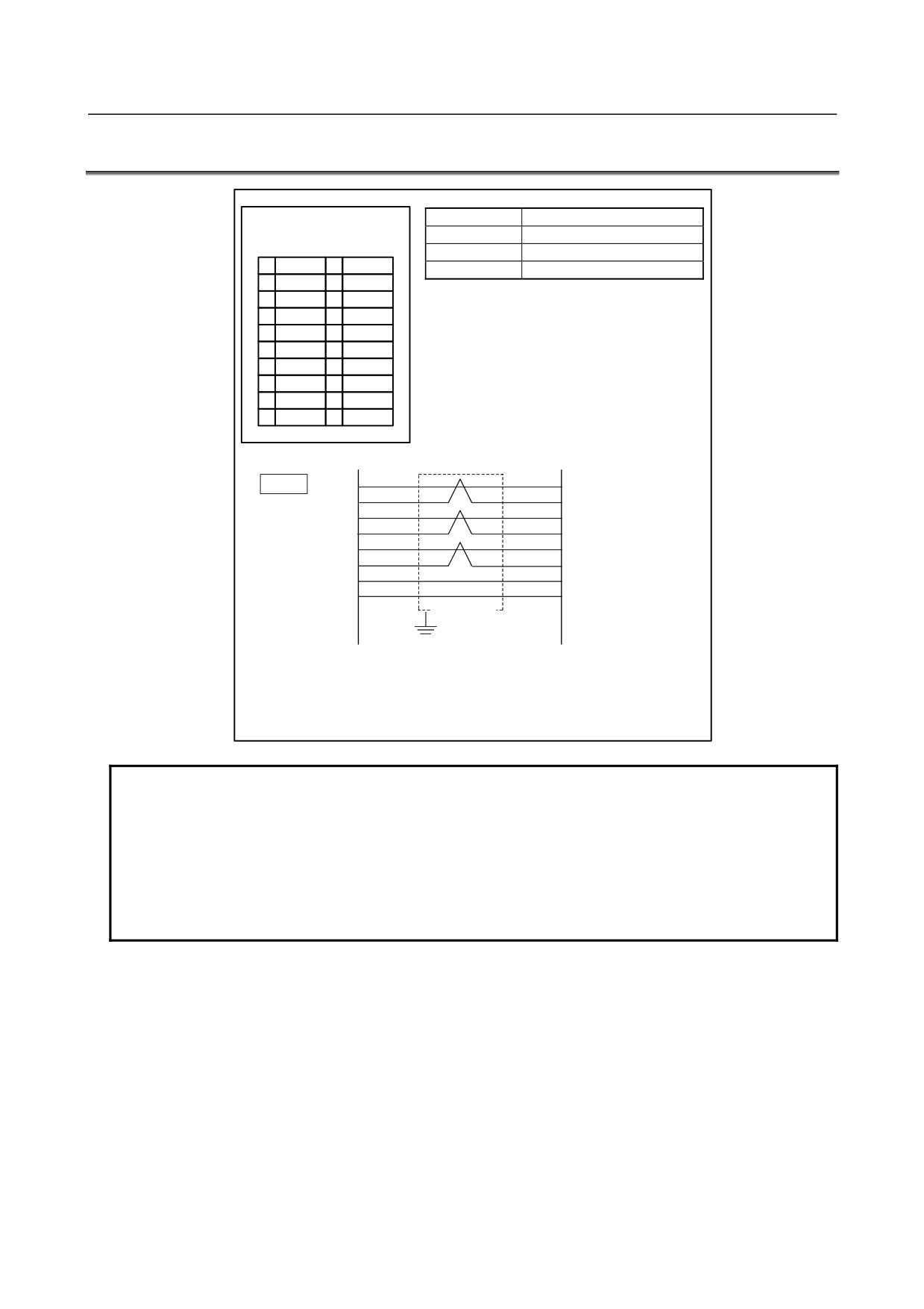
1 ENB1 and ENB2 are turned on when the spindle voltage command is valid.
These signals are used when other than the FANUC analog spindle servo unit is
used.
2 The rating of analog output is shown below.
Output voltage: ±10 V
Output current: 2 mA (Max.)
Output impedance: 100 Ω
3 The signals enclosed by parentheses ( ) are used for high-speed skip (HDI).
4 The upper connector specification of JA40 is for the LCD-mounted type.
The lower connector name in parentheses is for the stand-alone type.
- 80 -
B-64303EN/03
6.SPINDLE CONNECTION
6.3
POSITION CODER
CNC
JA41 (main board)
Signal name
Description
FI80-20P, DF1R020WB1
SC,*SC
Position coder C phase signal
(PCR-EV20MDT)
PA,*PA
Position coder A phase signal
1
(
)
11
(
)
PB,*PB
Position coder B phase signal
2
(
)
12
0V
3
(
)
13
(
)
4
(
)
14
0V
5
PA
15
SC
6
*PA
16
0V
7
PB
17
*SC
8
*PB
18
+5V
9
+5V
19
(
)
10
(
)
20
+5V
Cable connection
1
3
JA41
PA
A(PA)
2
4
*PA
N(*PA)
3
1
PB
C(PB)
4
2
*PB
R(*PB)
15
15
SC
B(PZ)
17
17
*SC
P(*PZ)
19
19
+5V
H
10
10
0V
K
Shield
Ground plate
Recommended cable connector:
PCR-E20FA (manufactured by Honda Tsushin Kogyo)
FCN-247J020-G/E (manufactured by Fujitsu)
52622-2011 (manufactured by Molex Japan)
Recommended wire specification: A66L-0001-0284#10P (28AWG × 10 pairs)
NOTE
1 The signals enclosed by parentheses ( ) are used for serial spindles.
These
signals are not used for analog spindles.
2 The 15-pin soldering connector (FI40B-2015S (conventionally, FI40-2015S))
manufactured by Hirose Electric cannot be used for the connector on the cable
side.
3 The upper connector specification of JA41 is for the LCD-mounted type.
The lower connector name in parentheses is for the stand-alone type.
- 81 -
7.SERVO INTERFACE
B-64303EN/03
7 SERVO INTERFACE
7.1
CONNECTION TO THE SERVO AMPLIFIERS
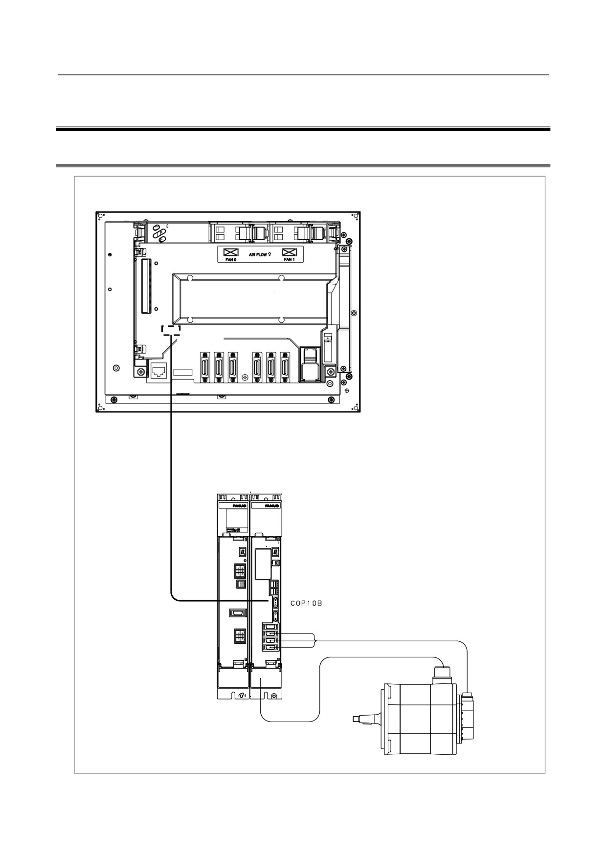
Control unit
Rear of unit
COP10A-1
This figure shows an example of connection for the
LCD-mounted type.
- 82 -
B-64303EN/03
7.SERVO INTERFACE
7.1.1
Overview
This chapter generally describes connections between this CNC and servo units.
For details on connections to servo amplifiers, refer to the manual of each servo amplifier.
7.1.2
Interface to the Servo Amplifiers
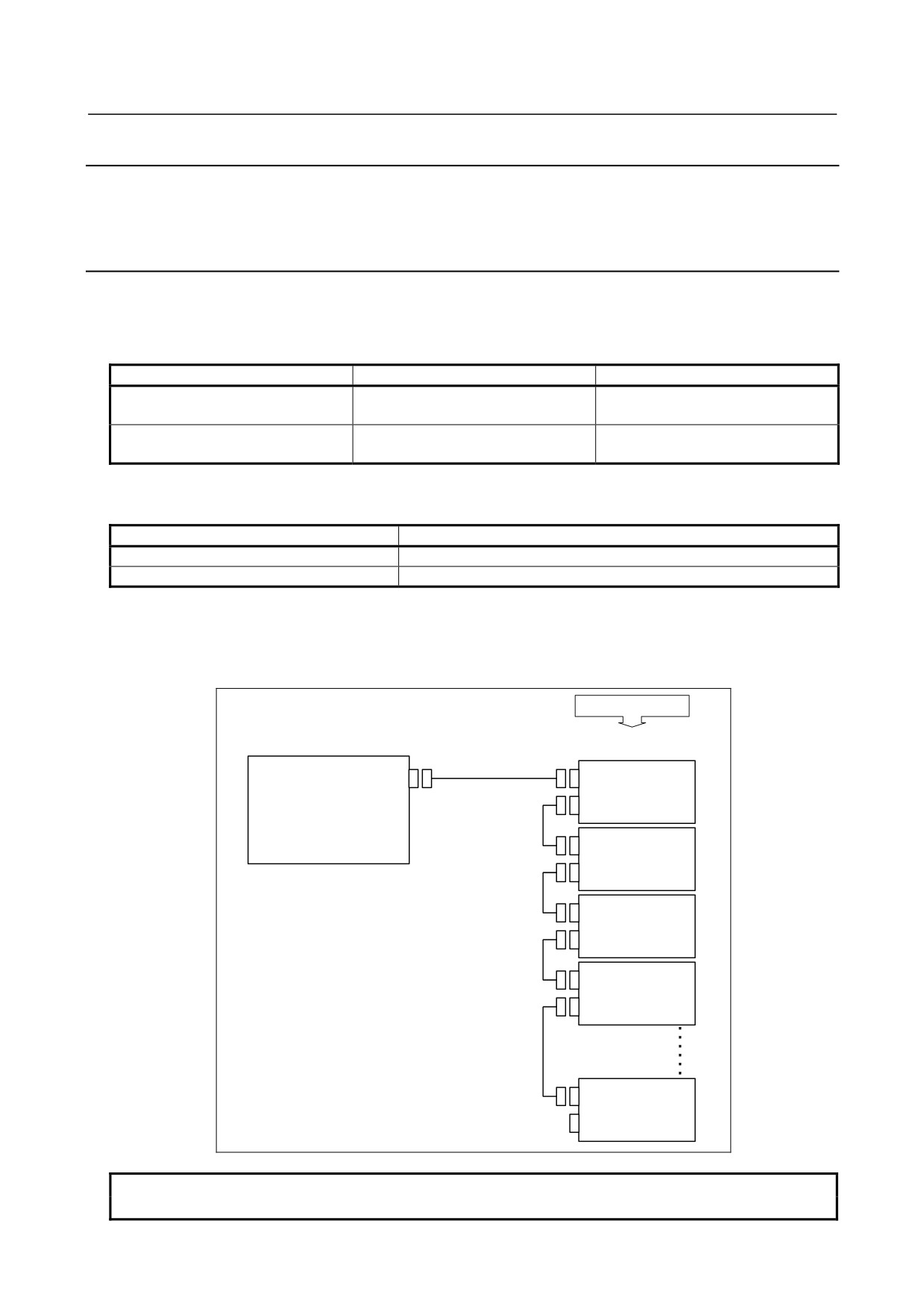
The connections between the CNC control unit and servo amplifiers should be made using optical cables.
The optical connector is present on the axis card.
<Optical cable types>
Usage
Cable drawing number
Cable length restriction
For internal connection
A02B-0236-K851 to -K856
Within 10 m
(A66L-6001-0023#~)
For external connection
Within 50 m
A66L-6001-0026#~
Within 40 m (between slave units)
<Cable length restriction>
(1)
Total cable length of each FSSB line is as follows
Control mode
Maximum total length
HRV2
500m
HRV3
200m
(2)
The cable length between CNC and the first slave unit is
•
Within 50m with A66L-6001-0026#~
(3)
Within 40m between slave units
Slave units
Control unit
Servo amplifier
FSSB line
2)
COP10A-1
COP10B
COP10A
Optical fiber cable
3)
COP10B
COP10A
3)
COP10B
COP10A
3)
COP10B
COP10A
Separate
detector
interface unit
3)
COP10B
COP10A
NOTE
For details and handling of optical cables, see Appendix D.
- 83 -
7.SERVO INTERFACE
B-64303EN/03
7.2
SEPARATE DETECTOR INTERFACE
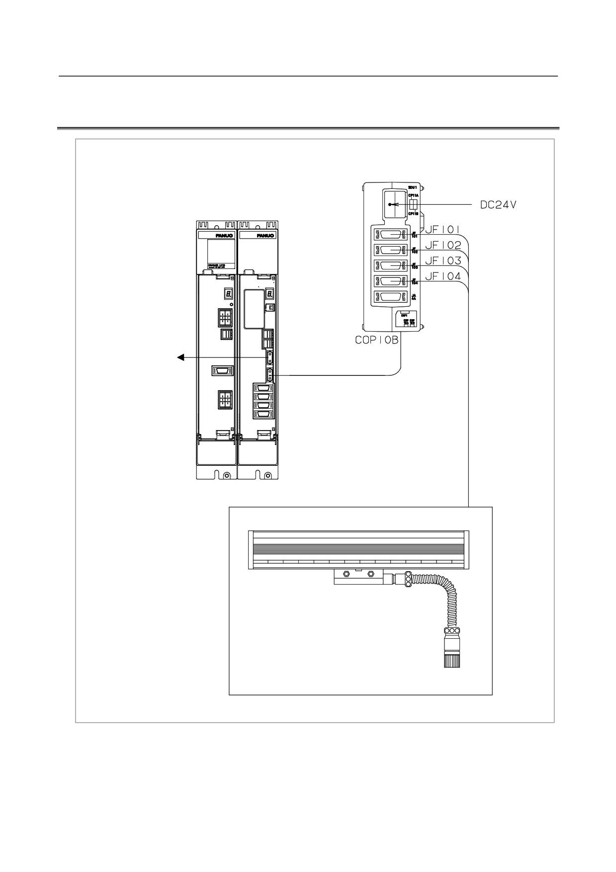
Separate detector interface unit
CP11A
Servo amplifier
Control unit or the
previous-stage servo
COP10B
amplifier
COP10A
Digital output
Linear encoder or rotary encoder
- 84 -
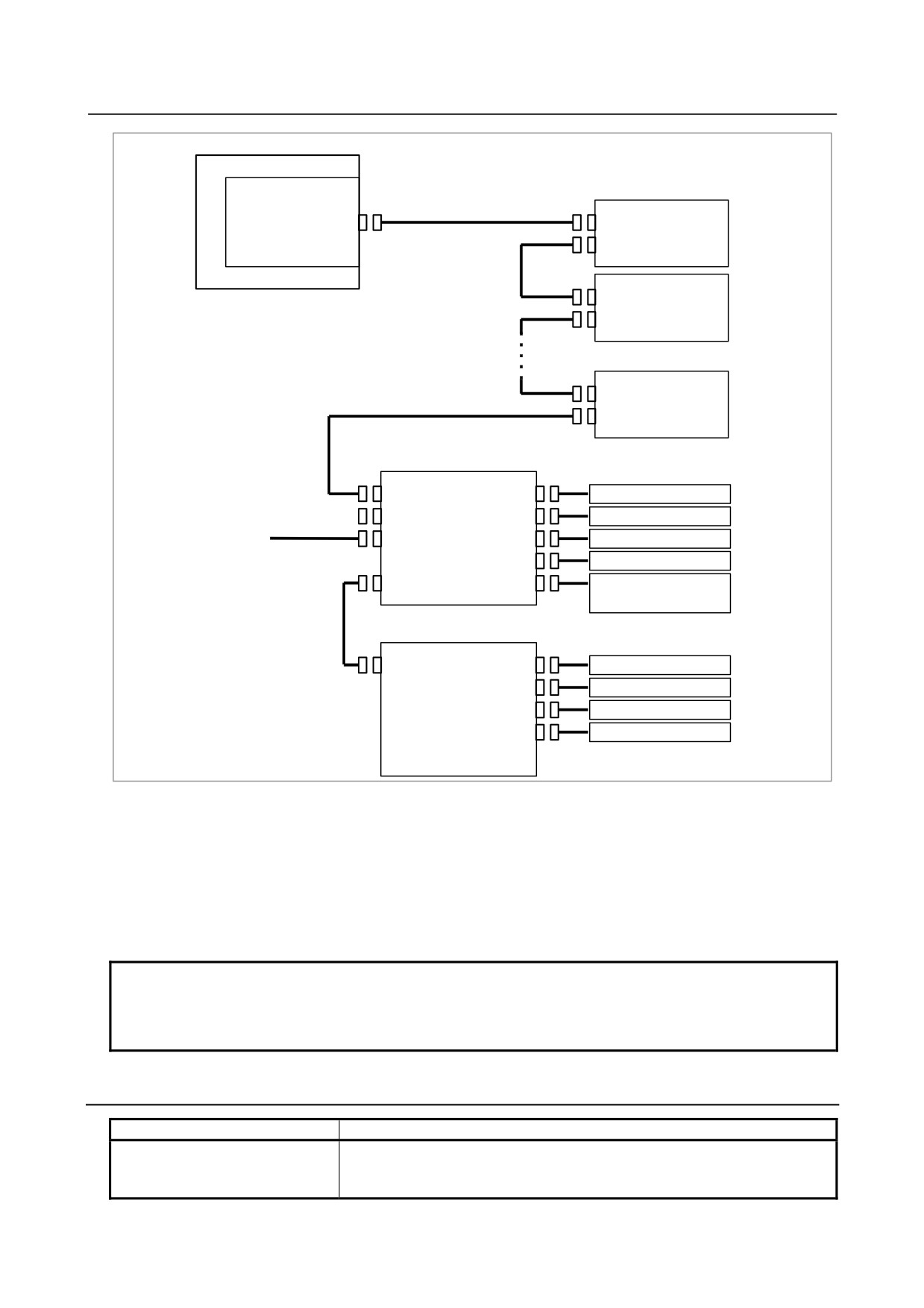
B-64303EN/03
7.SERVO INTERFACE
CNC
Servo amplifier
Servo card
Optical fiber cable
COP10A
COP10B
COP10A
COP10B
COP10A
COP10B
Optical fiber cable
COP10A
Separate detector interface unit (basic)
COP10B
JF101
Linear encoder axis 1
COP10A
JF102
Linear encoder axis 2
24VDC
CP11A
JF103
Linear encoder axis 3
JF104
Linear encoder axis 4
CNF1
JA4A
Battery for absolute
position detector
Flat cable
Separate detector interface unit (additional)
CNF2
JF105
Linear encoder axis 5
JF106
Linear encoder axis 6
JF107
Linear encoder axis 7
JF108
Linear encoder axis 8
When a separate detector such as a separate rotary encoder or linear encoder is used, a separate detector
interface unit is required. The separate detector interface unit is connected through an optical fiber cable
as an unit on an FSSB line.
A separate detector interface unit consists of basic units and additional units. Up to four pulse coders or
liner scales can be connected by adding an additional unit (up to eight units can be connected as a total).
An additional unit is connected to a basic unit through a flat cable. The maximum number of separate
detector interface units that can be connected to an FSSB line is two for HRV2 and HRV3.
NOTE
1 Unused optical connectors must be covered with the caps.
2 When using an encoder with an analog output of 1 Vp-p, see the description of
the analog input separate detector interface.
7.2.1
Separate Detector Interface Unit Specification
Item
Specification
Power supply capacity
Voltage
24 VDC ±10%
Current
0.9 A (basic unit only)
1.5 A (basic unit + additional unit)
- 85 -
7.SERVO INTERFACE
B-64303EN/03
Item
Specification
Ordering information
A02B-0303-C205 (basic)
A02B-0236-C204 (additional)
Method of installation
An interface unit can be installed by using screws or a DIN rail.
7.2.2
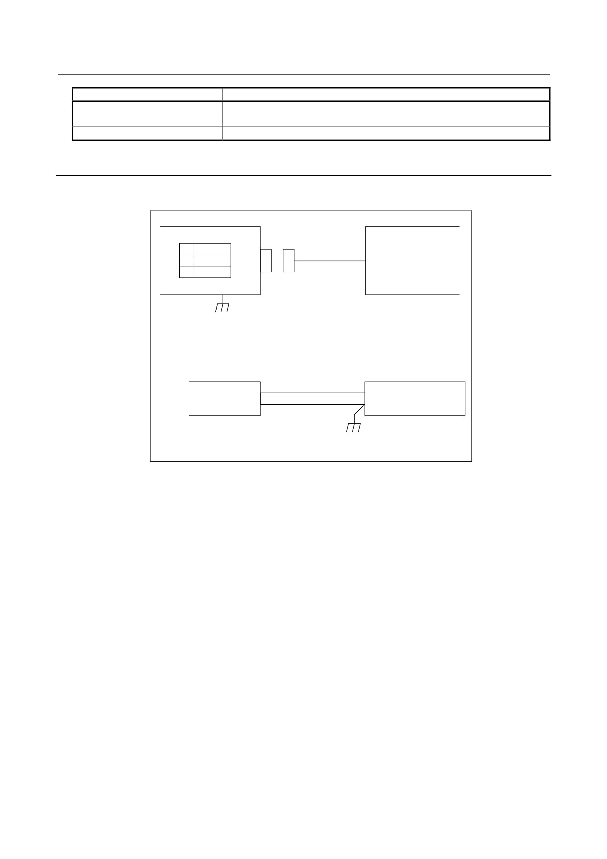
Connection of Power Supply
Power to the separate detector interface unit should be supplied from an external 24 V DC power supply.
An extended unit is powered by a basic unit.
Separate detector interface unit (basic)
External power supply
CP11A
1
+24V
24 VDC regulated power
2
0V
supply
3
24 VDC ±10%
GND
Cable
CP11A
AMP JAPAN
1-178288-3 (Housing)
1-175218-5 (Contact)
External power supply
Select a connector that
+24V (1)
matches the pin layout of
0V (2)
the external power supply.
Recommended cable specification: A02B-0124-K830 (5 m)
(The external power supply end of the cable is provided with M3 crimp terminals.)
The 24 VDC input to CP11A can be output at CP11B for use in branching. The connection of CP11B is
identical to that of CP11A. In this case, the power supplied to CP11A should be equal to the sum of the
rating of the separate detector interface unit and that of the units after CP11B.
Be sure to ground the 0-V line of the power supply to the separate detector interface unit. In addition,
keep any noise source (such as an AC power cable and contactor) away from the power line of the
separate detector interface unit as far as possible to prevent noise from being picked up through the power
line.
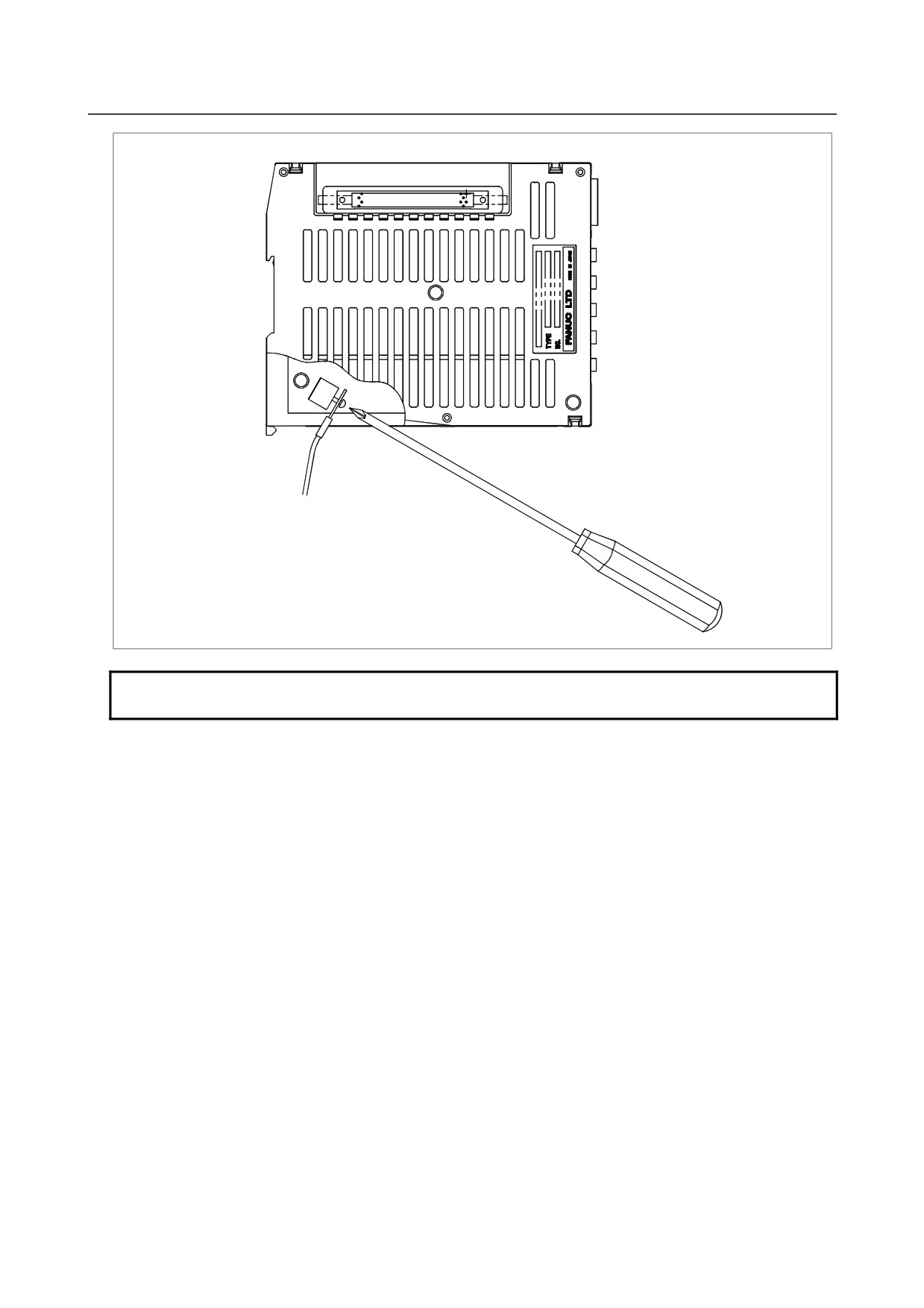
Secure the ground line to the ground terminal (GND) for signals of a separate detector interface unit,
which is located at the bottom of the unit, with an M3 screw as shown in the figure below. Connect the
ground line to the ground plate of the cabinet.
- 86 -
B-64303EN/03
7.SERVO INTERFACE
GND
To ground plate of cabinet
NOTE
The torque with which a screw is tightened is 5 kgf⋅cm or less.
- 87 -
7.SERVO INTERFACE
B-64303EN/03
7.2.3
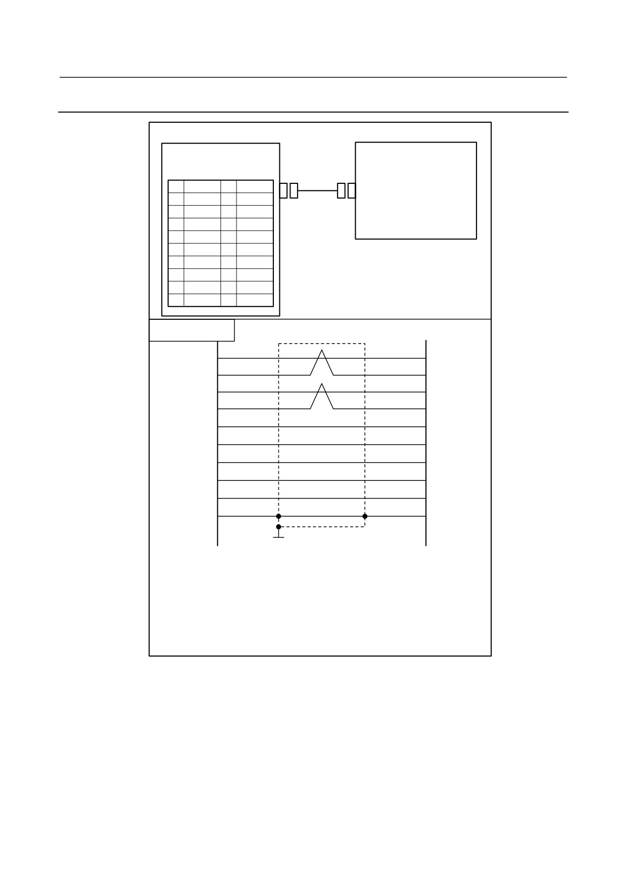
Separate Detector Interface (Serial Interface)
Separate detector interface unit
Separate detector
JF101 to JF108
(PCR-EV20MDT)
1
SD
11
2
*SD
12
0V
3
13
4
14
0V
5
REQ
15
6
*REQ
16
0V
7
(+6V)
17
The +6V signal is provided for absolute
8
18
+5V
position detectors that
require battery
9
+5V
19
backup.
10
20
+5V
Cable connection
1
SD
SD
2
*SD
*SD
5
REQ
REQ
6
*REQ
*REQ
7
(+6V)
(+6V)
18
+5V
+5V
20
+5V
+5V
12
0V
0V
14
0V
0V
16
Shielded drain wire
0V
FG
Shield
(Frame
Ground plate
Recommended cable:
A66L-0001-0286 (#20AWG × 6 + #24AWG × 3-pair)
Recommended connectors:
PCR-E20FA (Honda Tsushin Kogyo)
FI30-20S (Hirose Electric)
FCN-247J020-G/E (Fujitsu)
52622-2011 (Molex)
FI40B-2015S (Hirose Electric)
- 88 -

B-64303EN/03
7.SERVO INTERFACE
NOTE
1 The +5V signals above can be used to feed power to the detectors. The supply
current per linear scale is 0.35 A maximum.
Lower limit of the 5V signals:
4.95 V for the basic unit, and 4.9 V for the
additional unit
2 If the cable is connected to JA4A when the separate absolute pulse coder
battery case contains the battery, the battery voltage is applied to the battery
power supply pin (+6 V) for each of the feedback connectors (JF101 to JF108).
In this case, if the battery line and 0 V are short-circuited, the battery may heat
up or the protection circuit within the separate detector interface unit may fail.
First, make sure the battery case contains no battery or the cable is not
connected to JA4A. Then, complete all cabling work and confirm cables are
correctly connected. Finally, place the battery or connect the cable to JA4A.
- 89 -
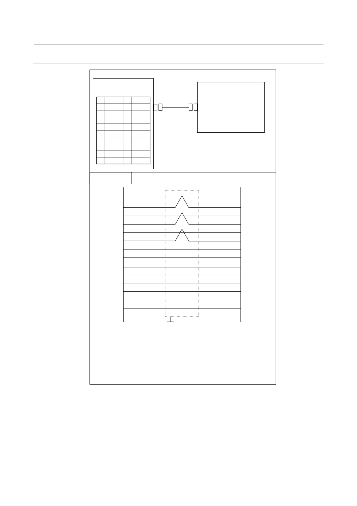
7.SERVO INTERFACE
B-64303EN/03
7.2.4
Separate Detector Interface (Parallel interface)
Separate detector interface unit
Separate detector
JF101 to JF108
(PCR-EV20MDT)
1
PCA
11
2
*PCA
12
0V
3
PCB
13
4
*PCB
14
0V
5
PCZ
15
6
*PCZ
16
0V
7
(+6V)
17
8
(REQ)
18
+5V
The +6V and REQ signals are provided for
9
+5V
19
absolute position
detectors
that require
10
20
+5V
battery backup.
Cable connection
1
PCA
PCA
2
*PCA
*PCA
3
PCB
PCB
4
*PCB
*PCB
5
PCZ
PCZ
6
*PCZ
*PCZ
7
(+6V)
(+6V)
8
(REQ)
(REQ)
9
+5V
+5V
18
+5V
+5V
20
+5V
+5V
12
0V
0V
14
0V
0V
16
0V
0V
Shield
Ground plate
RECOMMENDED CABLE MATERIAL
A66L-0001-0286
(#20AWG × 6 + #24AWG × 3-pair)
Recommended connectors:
PCR-E20FA (Honda Tsushin Kogyo)
FI30-20S (Hirose Electric)
FCN-247J020-G/E (Fujitsu)
52622-2011 (Molex)
FI40B-2015S (Hirose Electric)
- 90 -
B-64303EN/03
7.SERVO INTERFACE
NOTE
1 The +5V signals above can be used to feed power to the detectors. The supply
current per detector is 0.35 A maximum.
Minimum tolerance to 5 V:
4.95 V for main unit and 4.9 V for added section
2 If the cable is connected to JA4A when the separate absolute pulse coder
battery case contains the battery, the battery voltage is applied to the battery
power supply pin (+6 V) for each of the feedback connectors (JF101 to JF108).
In this case, if the battery line and 0 V are short-circuited, the battery may heat
up or the protection circuit within the separate detector interface unit may fail.
First, make sure the battery case contains no battery or the cable is not
connected to JA4A. Then, complete all cabling work and confirm cables are
correctly connected. Finally, place the battery or connect the cable to JA4A.
7.2.5
Input Signal Requirements (Parallel interface)
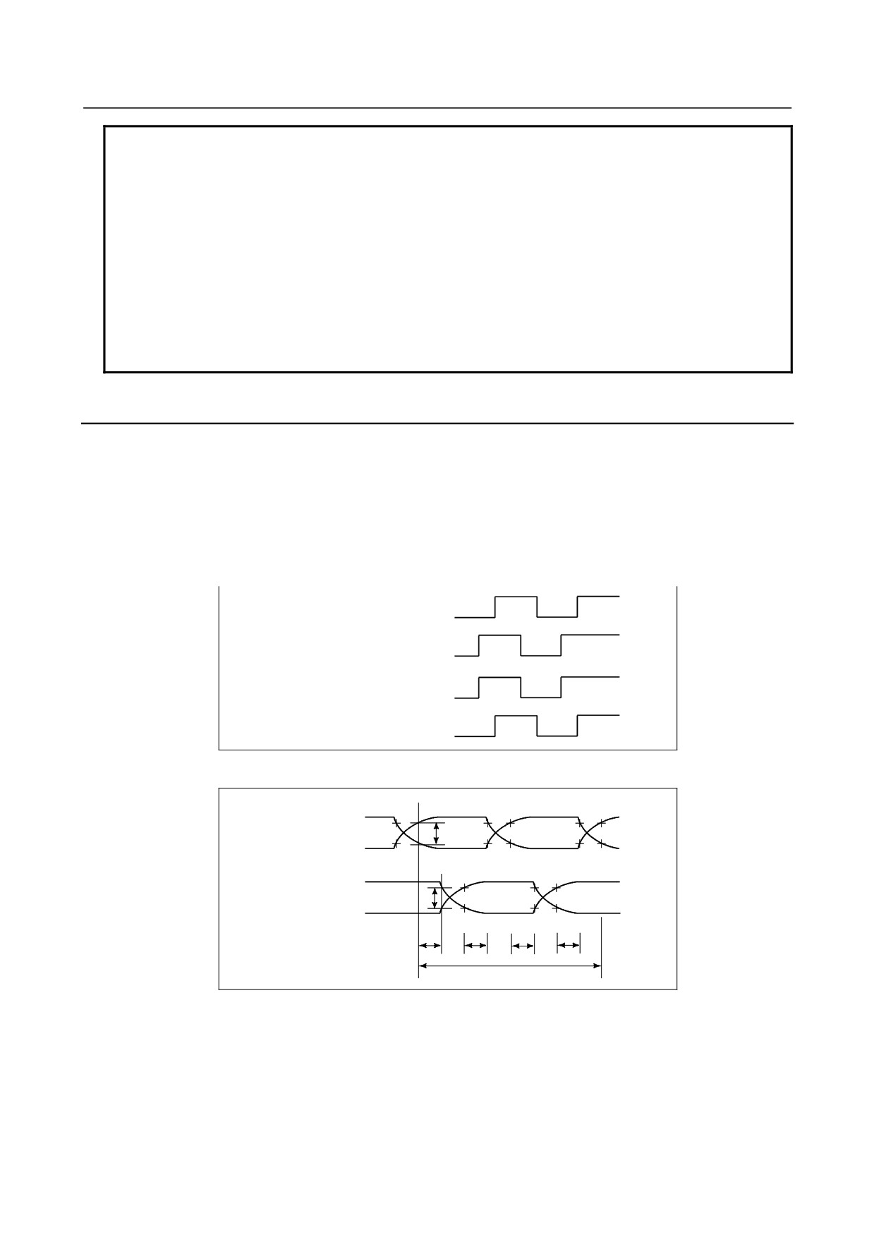
The feedback signals from the separate detectors connected via the parallel interface are defined as
follows:
(1) A and B phase signal input
This is a method to input position information by the mutual 90 degree phase slip of A and B phase
signals.
Detection of the position is performed with the state in which the B phase is leading taken as a shift
in the plus direction, and the state in which the A phase is leading as a shift in the minus direction.
Shift in plus direction A phase signal
B phase signal
Shift in minus direction A phase signal
B phase signal
(2) Phase difference and minimum repeat frequency
A
PCA/*PCA
0.5V
*PCA/PCA
B
PCB/*PCB
0.5V
*PCB/PCB
Td
Td
Td
Td
Tp
- 91 -
7.SERVO INTERFACE
B-64303EN/03
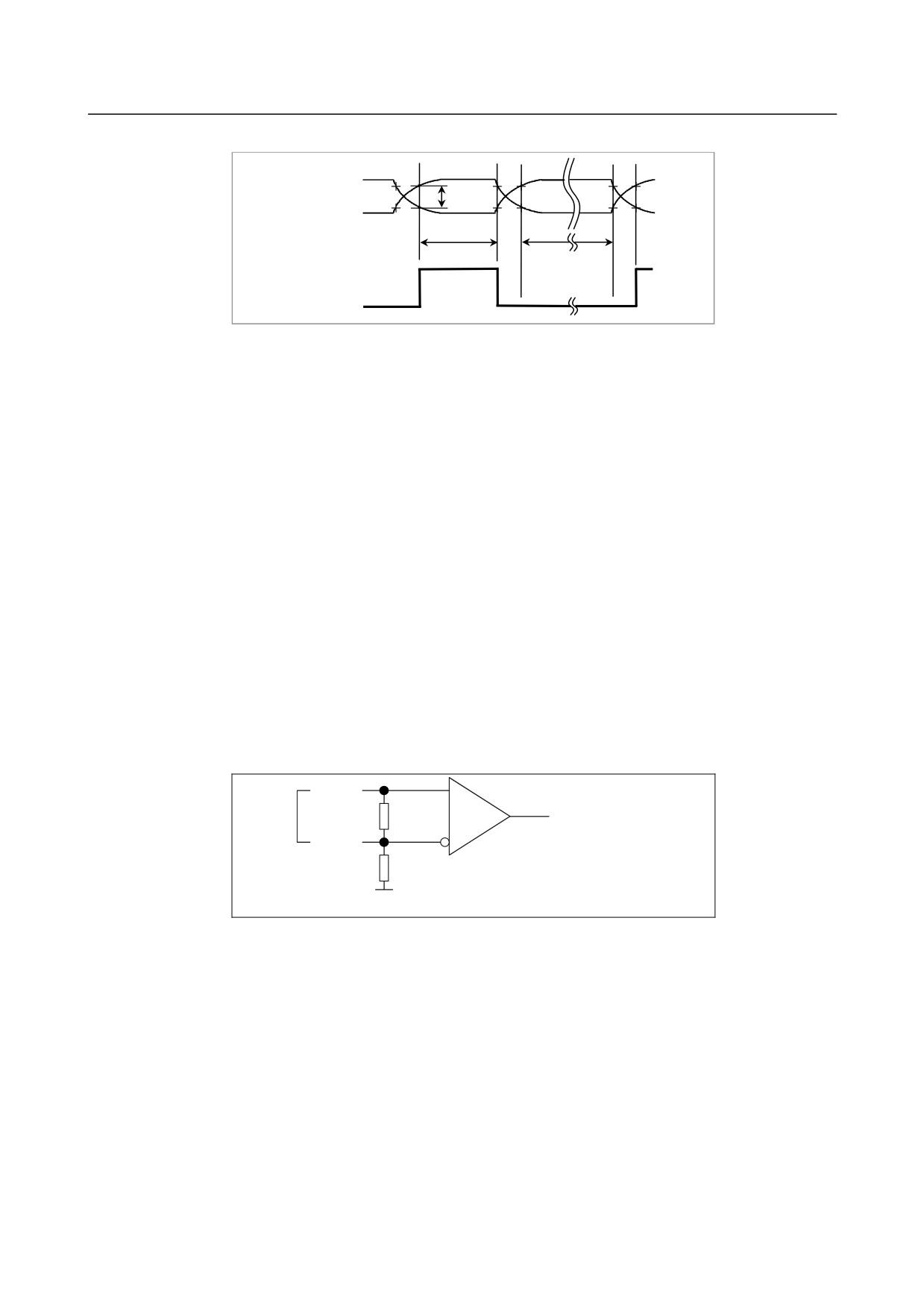
(3) Z phase signal input
*PCZ
0.5V
PCZ
Tw
TOFF
Z phase signal
Time requirements
Requirements for the signals at the input pins of input connectors JF101 to JF108. The signals for these
connectors are differential input signals with A and B phases. An important factor is time TD from
point A, when the potential difference between PCA and *PCA exceeds 0.5V, to point B, when the
potential difference between PCB and *PCB becomes lower than 0.5V. The minimum value of TD is
0.15msec. The period and pulse width of the signals must be long enough to satisfy the above
requirements.
The Z phase signal is also a differential signal. The following conditions are stipulated for the time from
when the potential difference between PCZ and *PCZ exceeds 0.5 V to when the potential difference
becomes lower than 0.5 V.
Tw ≥ 1/4 frequency of A phase or B phase
TOFF > 1.5 msec
Input voltage requirements
The voltage of the A and B phase signals must meet the following requirements:
High level:
2.4 V or more
Low level:
0.8 V or less
Receiver circuit
PCA
A-phase
110Ω
signal
*PCA
560Ω
The same circuit is used for B-phase
signals (PCB and *PCB)
5V
Rotation directions of a servo motor and separate rotary encoder
If a separate rotary encoder rotates in a direction opposite to the direction of servo motor rotation when
the servo motor is rotating, the connection of the feedback cable from the separate rotary encoder must be
changed as follows:
(1) Exchange signal PCA with signal PCB.
(2) Exchange signal *PCA with signal *PCB.
- 92 -
B-64303EN/03
7.SERVO INTERFACE
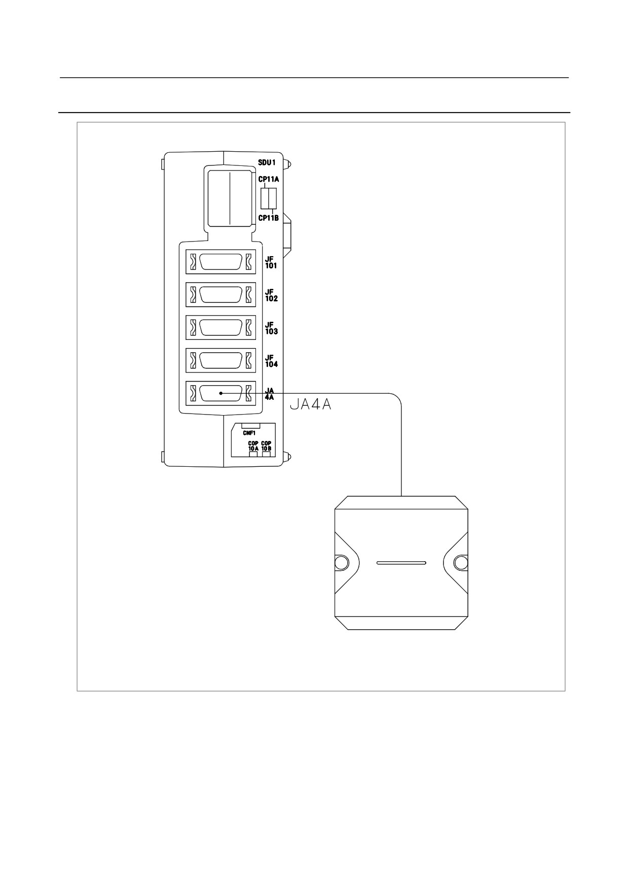
7.2.6
Connection of Battery for Absolute Position Detector
Separate detector interface unit
Absolute pulse coder battery case
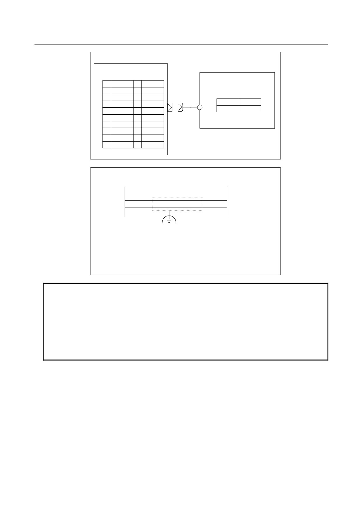
When the separate absolute position detector that needs battery backup is connected, the battery case for
the separate absolute pulse coder must be connected.
- 93 -
7.SERVO INTERFACE
B-64303EN/03
Separate detector interface unit
Battery case for the separate
absolute pulse coder
JA4A
(PCR-EV20MDT)
01
11
02
12
(M3 terminal)
03
0V
13
+
-
04
14
+6V
0V
05
15
06
16
07
+6V
17
08
18
09
19
10
20
Cable connection
JA4A
Battery case
7
+
+6V
+6V
3
-
0V
0V
RECOMMENDED CABLE MATERIAL:
≥0.2 mm2 (7/0.18)
Recommended connectors:
PCR-E20FA (Honda Tsushin Kogyo)
FI30-20S (Hirose Electric)
FCN-247J020-G/E (Fujitsu)
52622-2011 (Molex)
NOTE
If the cable is connected to JA4A when the separate absolute pulse coder
battery case contains the battery, the battery voltage is applied to the battery
power supply pin (+6 V) for each of the feedback connectors (JF101 to JF108).
In this case, if the battery line and 0 V are short-circuited, the battery may heat
up or the protection circuit within the separate detector interface unit may fail.
First, make sure the battery case contains no battery or the cable is not
connected to JA4A. Then, complete all cabling work and confirm cables are
correctly connected. Finally, place the battery or connect the cable to JA4A.
- 94 -
B-64303EN/03
7.SERVO INTERFACE
7.2.7
Connection Between the Basic Unit and Additional Unit
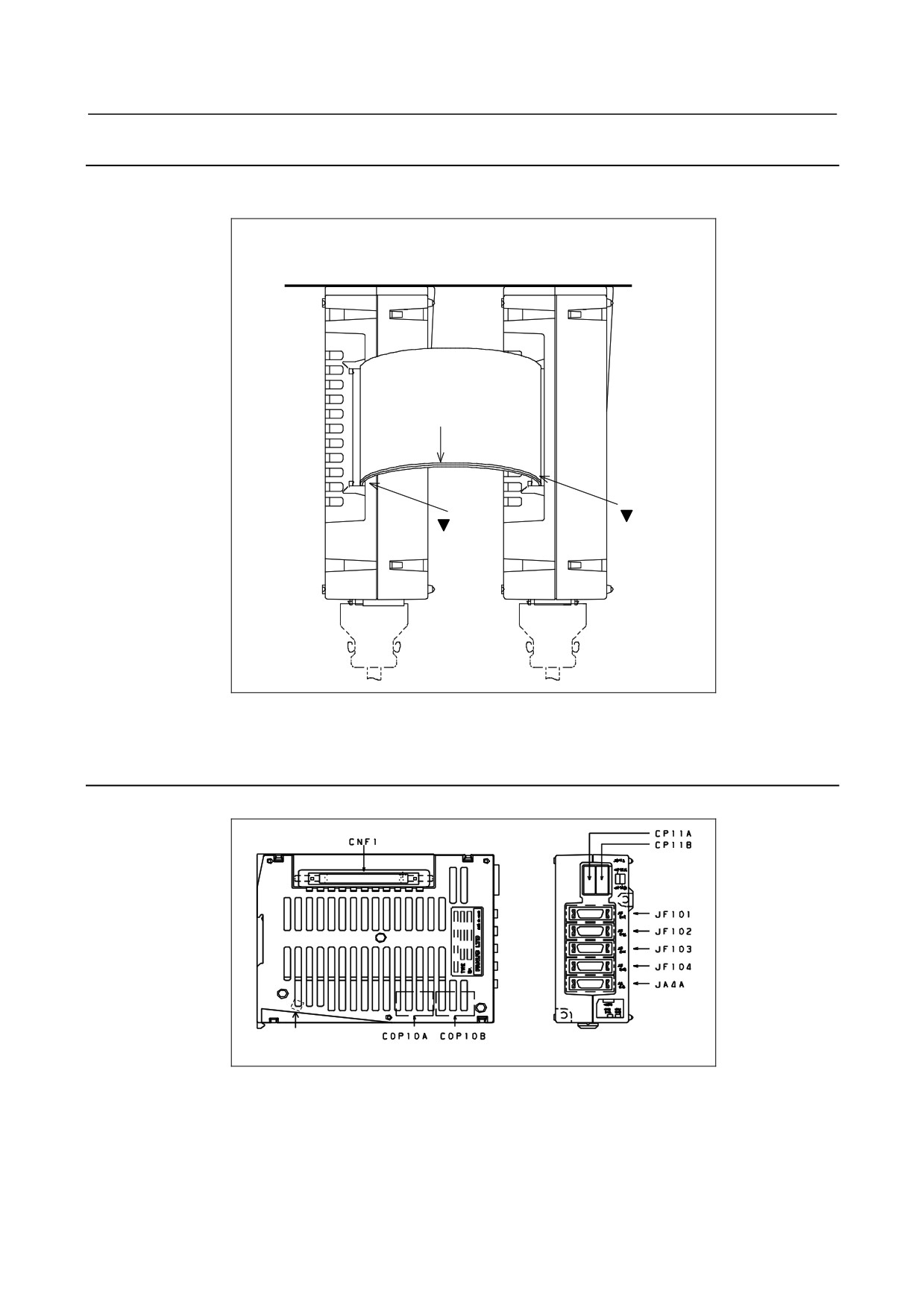
A flat cable is used to make a connection between the basic unit and additional unit as shown below.
A flat cable not longer than 100 mm must be used.
Units viewed from top
Basic unit
Additional unit
Mounting
surface
CNF1
CNF2
Marking
mark
mark
Place an order on a flat cable together with separate detector interface units.
7.2.8
Connector Locations
Connector locations on the basic unit
GND
- 95 -
7.SERVO INTERFACE
B-64303EN/03
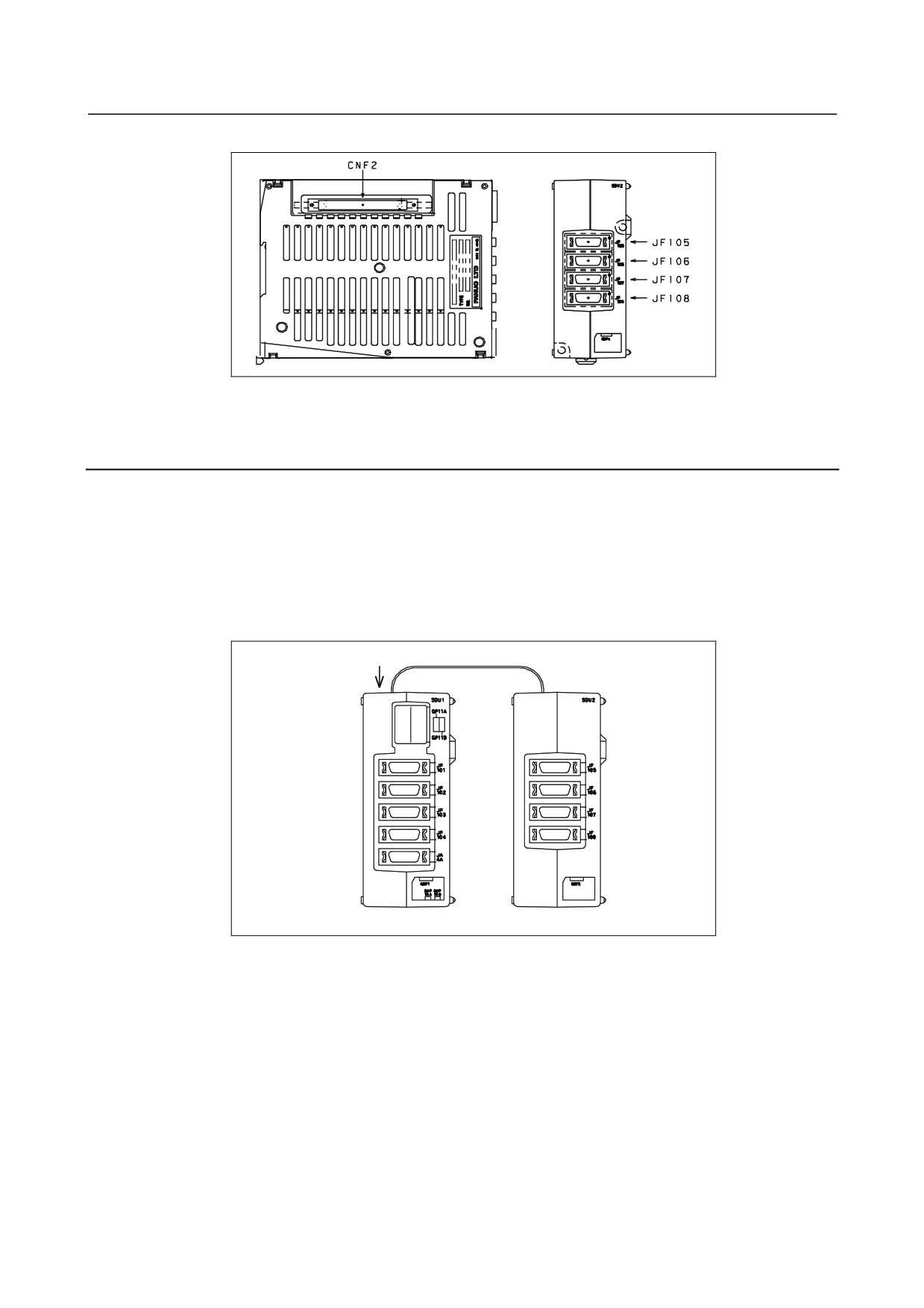
Connector locations on the additional unit
For the outside dimensions, see Appendix A.
7.2.9
Installation
1)
Notes on installation
(1) Use an interface unit in a completely enclosed cabinet.
(2) Install an interface unit on a vertical surface, and provide a space of 100 mm above and below
the unit. Below an interface unit, do not place equipment that generates a large amount of
heat.
(3) When using a basic unit and additional unit, place the units as shown below so that the flat
cable connecting the units does not block the vent holes. A flat cable not longer than 100 mm
must be used.
Vent holes
Flat cable
Basic unit
Additional unit
- 96 -
B-64303EN/03
7.SERVO INTERFACE
2)
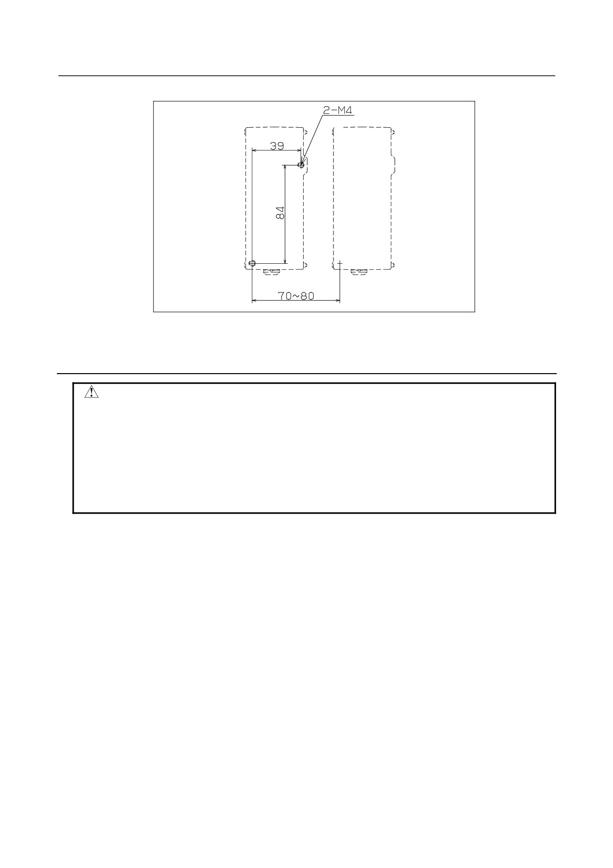
Installation using screws
Basic unit
Additional unit
When using both a basic unit and additional unit, install the units as shown above, with the mounting
holes horizontally separated by 70 to 80 mm.
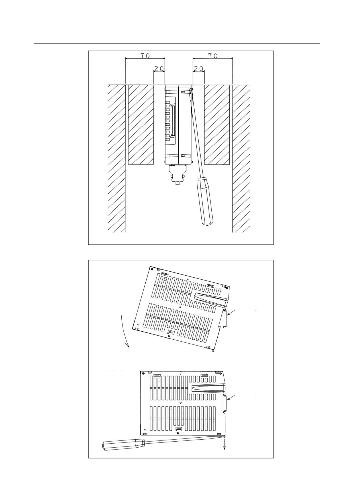
7.2.10 Notes on Installing a Separate Detector Interface Unit
CAUTION
To install/remove the unit, a screwdriver must be inserted obliquely. So,
sufficient access clearances are required on both sides of the unit. As a
guideline, if the front of an adjacent unit appears flush with the unit or slightly set
back, allow a clearance of about 20 mm between the unit and the adjacent unit.
If the front of an adjacent unit protrudes beyond the front of the unit, allow a
clearance of about 70 mm between the unit and the adjacent unit. Also, when
installing the unit near a side of the cabinet, allow a clearance of about 70 mm
between the unit and the side of the cabinet.
- 97 -
7.SERVO INTERFACE
B-64303EN/03
Access clearance near a separate detector interface unit
Installing the unit on the DIN rail
Installing the unit on
the DIN rail
DIN rail
Removing the unit
from the DIN rail
DIN rail
- 98 -
B-64303EN/03
7.SERVO INTERFACE
Installing the unit:
1.
Hook the unit on the top of the DIN rail.
2.
Push the unit in until it clicks.
Removing the unit:
1.
Push down the lock by using a screwdriver.
2.
Remove the unit by pulling the lower end of the unit towards you.
CAUTION
When removing the unit, be careful not to damage the lock by applying
excessive force. When installing and removing the unit, hold the upper and
lower ends of the unit so that stress is not applied to the side (that surface with
the slits) of the unit.
- 99 -
7.SERVO INTERFACE
B-64303EN/03
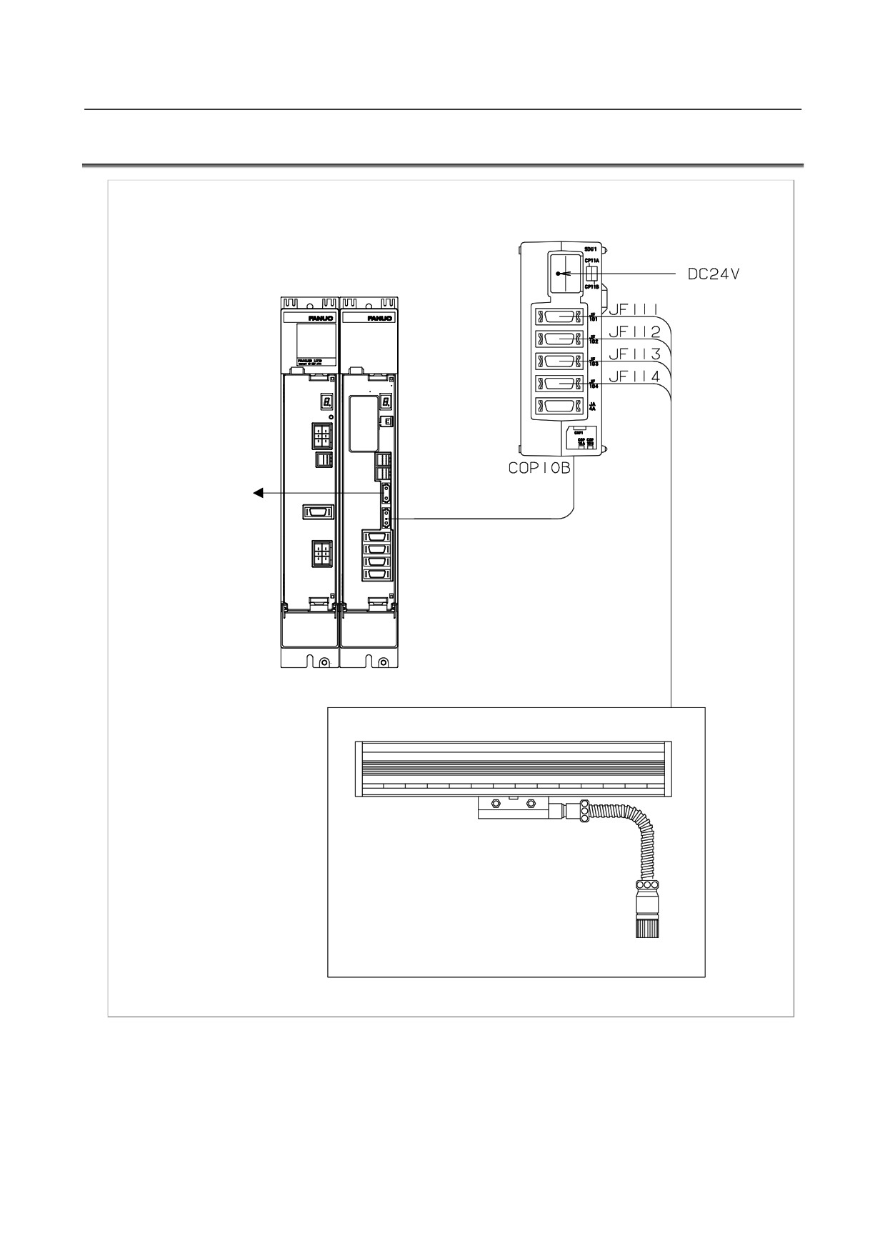
7.3
ANALOG INPUT SEPARATE DETECTOR INTERFACE
Analog input separate detector interface unit
CP11A
Servo amplifier
Control unit or the
COP10B
previous-stage servo
amplifier
COP10A
1 Vp-p output linear encoder or rotary
encoder
- 100 -
B-64303EN/03
7.SERVO INTERFACE
7.3.1
Overview
When a separate detector such as a rotary encoder or linear encoder with an analog output of 1 Vp-p is
used, an analog input separate detector interface unit is used. The analog input separate detector unit is
connected via an optical cable as a unit on the FSSB line. Up to four 1-Vp-p output separate detectors
can be connected to a basic unit.
One additional unit (A02B-0236-C204) can be connected to the basic unit with a flat cable. Four
separate detectors with digital output can be connected to the additional unit. When five or more 1-Vp-p
output separate detectors are to be used, more than one basic unit (analog input separate detector interface
unit) is required. The JA4A connector is provided for the battery for absolute position detectors
connected to the additional unit.
The maximum number of separate detector interface units that can be connected to one FSSB line is two
for HRV2 and HRV3, regardless of which input type, the analog input type or digital input type, is used.
NOTE
1 Unused optical connectors must be covered with the caps.
2 A digital output encoder refers to an encoder that outputs A and B rectangular
waveforms (parallel) or a FANUC serial interface output encoder (serial).
3 No 1-Vp-p output encoder can be connected to additional units.
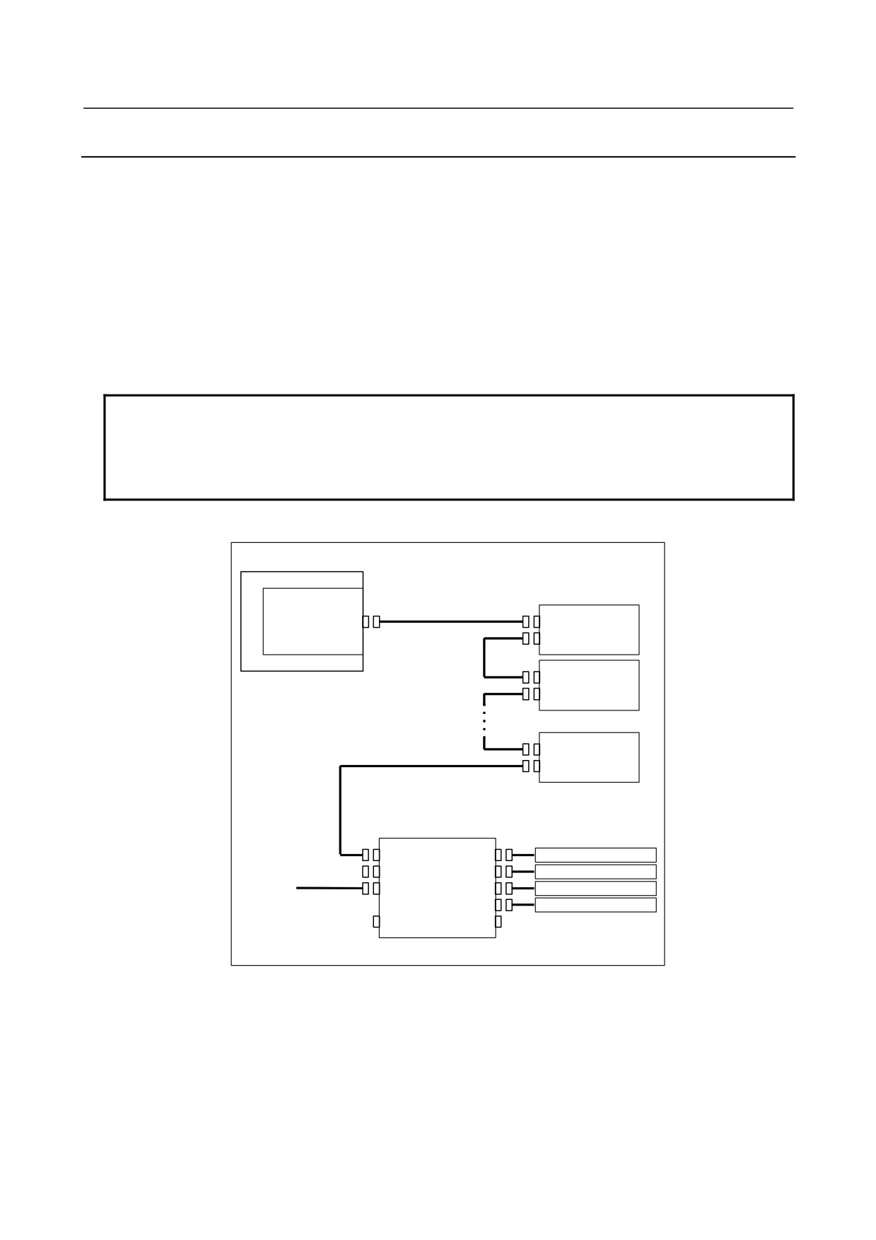
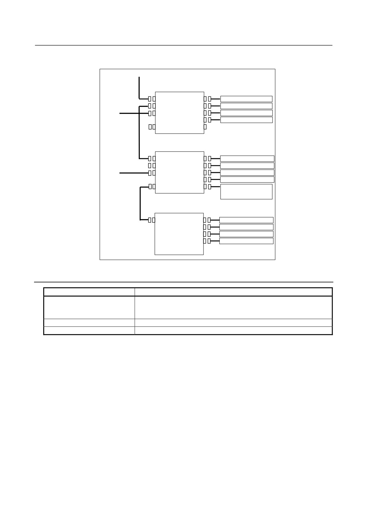
(1) Connecting 1-Vp-p output encoders to the 1st to 4th axes
CNC
Servo amplifier module
Servo card
Optical fiber cable
COP10A
COP10B
COP10A
COP10B
COP10A
COP10B
Optical fiber cable
COP10A
Analog input separate detector interface unit
COP10B
JF111
1Vp-p output encoder 1 axis
COP10A
JF112
1Vp-p output encoder 2 axes
24VDC
CP11A
JF113
1Vp-p output encoder 3 axes
JF114
1Vp-p output encoder 4 axes
CNF1
JA4A
- 101 -
7.SERVO INTERFACE
B-64303EN/03
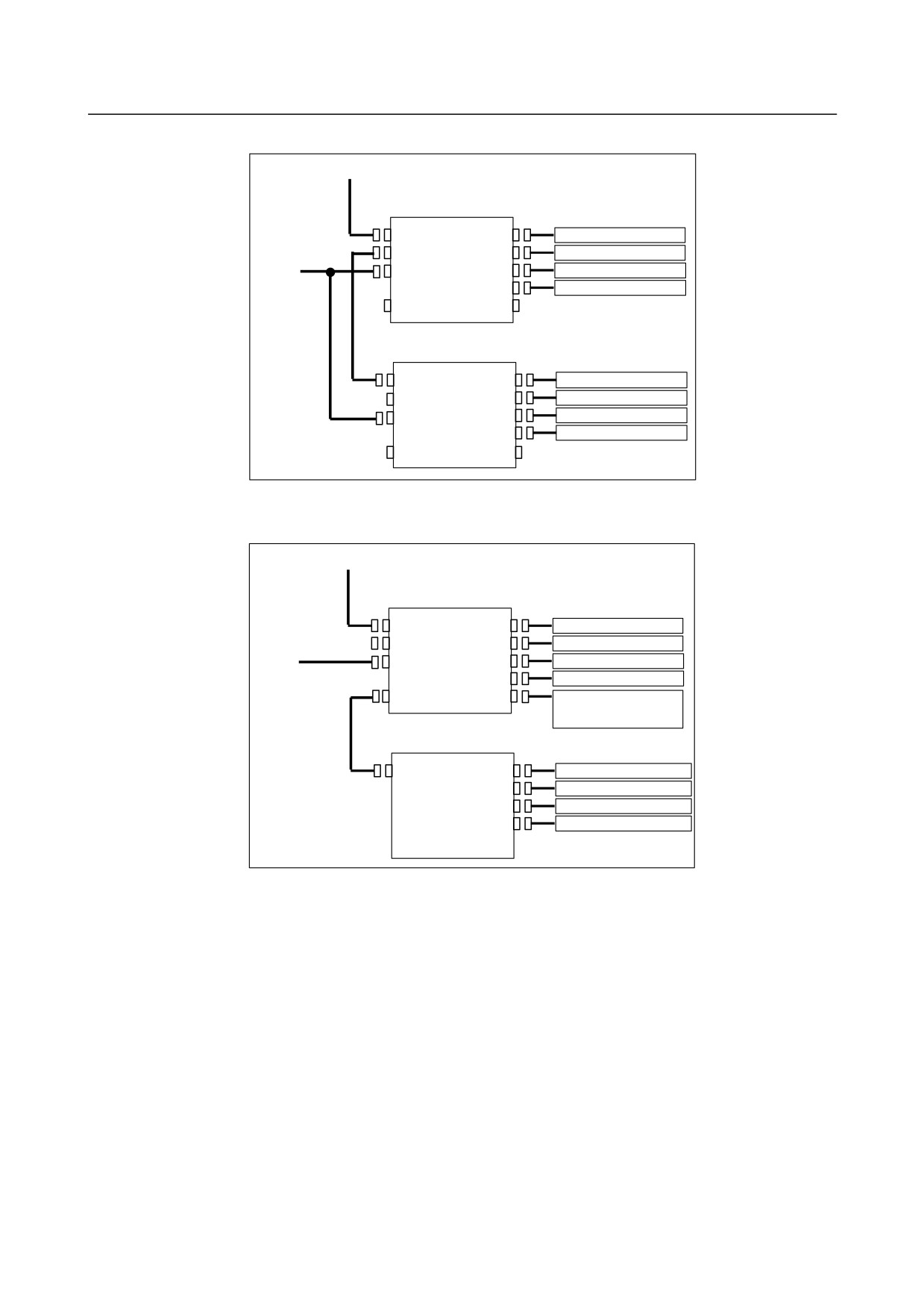
(2) Connecting 1-Vp-p output encoders to the 5th to 8th axes
Optical fiber cable
Analog input separate detector interface unit
COP10B
JF111
1Vp-p output encoder 1 axis
Optical fiber cable
COP10A
JF112
1Vp-p output encoder 2 axes
24VDC
CP11A
JF113
1Vp-p output encoder 3 axes
JF114
1Vp-p output encoder 4 axes
CNF1
JA4A
Analog input separate detector interface unit
JF111
COP10B
1Vp-p output encoder 5 axes
COP10A
JF112
1Vp-p output encoder 6 axes
CP11A
JF113
1Vp-p output encoder 7 axes
JF114
1Vp-p output encoder 8 axes
CNF1
JA4A
(3) Connecting 1-Vp-p output encoders to the 1st to 4th axes and digital output encoders to the 1st to
4th axes
Optical fiber cable
Analog input separate detector interface unit
COP10B
JF111
1Vp-p output encoder 1 axis
COP10A
JF112
1Vp-p output encoder 2 axes
24VDC
CP11A
JF113
1Vp-p output encoder 3 axes
JF114
1Vp-p output encoder 4 axes
CNF1
JA4A
Battery for separate absolute
position detectors connected to
Flat cable
additional unit
Separate detector interface unit (additional unit)
CNF2
JF105
Digital output encoder 1 axis
JF106
Digital output encoder 2 axes
JF107
Digital output encoder 3 axes
JF108
Digital output encoder 4 axes
- 102 -
B-64303EN/03
7.SERVO INTERFACE
(4) Connecting 1-Vp-p output encoders to the 1st to 4th axes and digital output encoders to the 5th to
8th axes
Optical fiber cable
Analog input separate detector interface unit
JF111
COP10B
Optical fiber cable
1Vp-p output encoder 1 axis
JF112
COP10A
1Vp-p output encoder 2 axes
24VDC
JF113
CP11A
1Vp-p output encoder 3 axes
JF114
1Vp-p output encoder 4 axes
CNF1
JA4A
Separate detector interface unit (basic unit)
JF101
COP10B
Digital output encoder 1 axis
JF102
COP10A
Digital output encoder 2 axes
24VDC
JF103
CP11A
Digital output encoder 3 axes
JF104
Digital output encoder 4 axes
CNF1
JA4A
Battery for separate absolute
detector
Flat cable
Separate detector interface unit (additional unit)
JF105
CNF2
Digital output encoder 5 axes
JF106
Digital output encoder 6 axes
JF107
Digital output encoder 7 axes
JF108
Digital output encoder 8 axes
7.3.2
Analog Input Separate Detector Interface Unit Specification
Item
Specification
Power supply capacity
Voltage
24 VDC ±10%
Current
0.9 A (basic unit only)
1.5 A (basic unit + additional unit)
Ordering information
A02B-0305-C201 (basic)
Method of installation
An interface unit can be installed by using screws or a DIN rail.
- 103 -
7.SERVO INTERFACE
B-64303EN/03
7.3.3
Connection of Power Supply
Power to the analog input separate detector interface unit should be supplied from an external 24 VDC
power supply. An extended unit is powered by a basic unit.
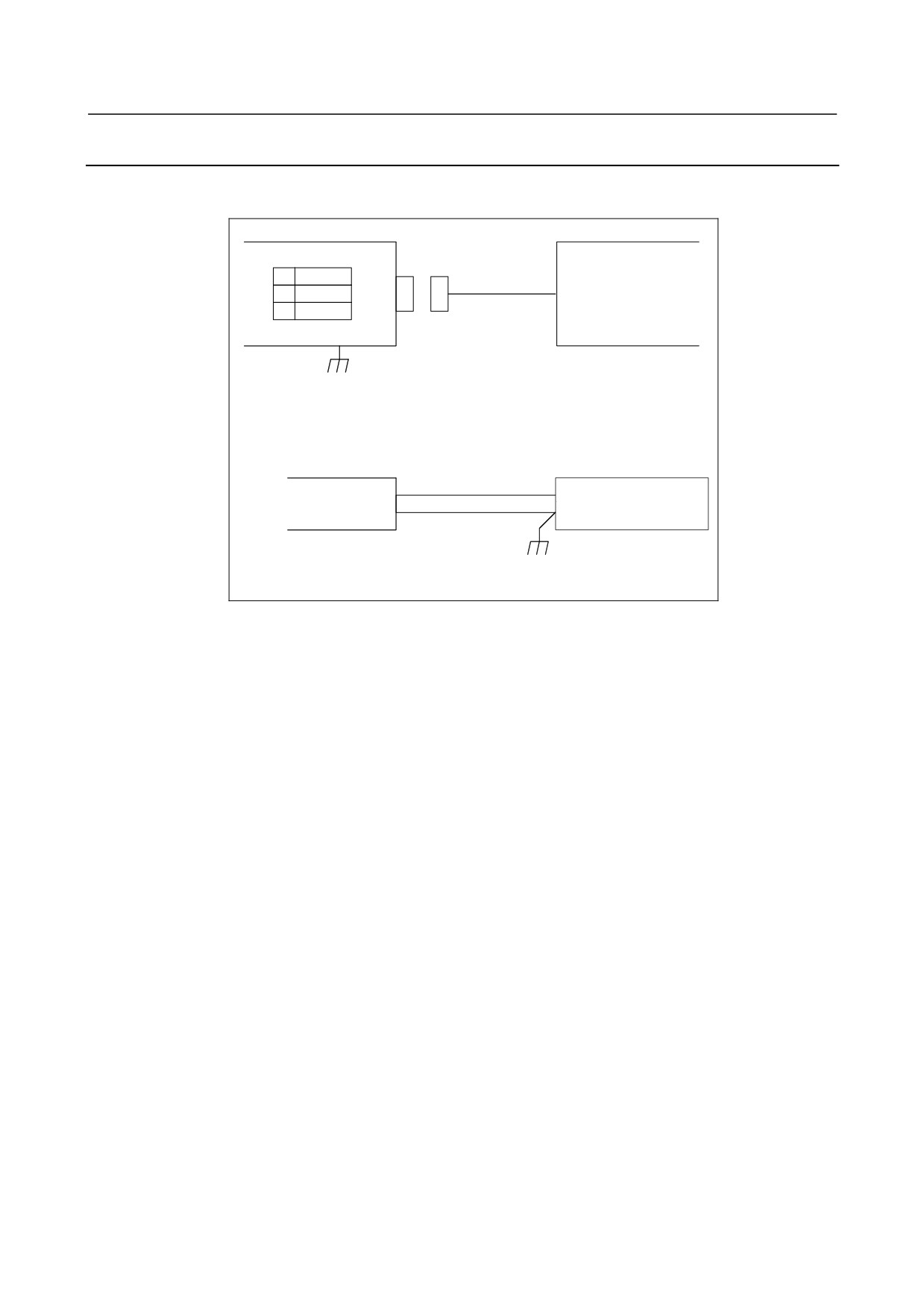
Analog input separate detector interface unit
External power supply
CP11A
1
+24V
24 VDC regulated power
2
0V
supply
3
24 VDC ±10%
GND
Cable
CP11A
AMP JAPAN
1-178288-3 (Housing)
1-175218-5 (Contact)
External power supply
Select a connector that
+24V (1)
matches the pin layout of
0V (2)
the external power supply.
Recommended cable specification: A02B-0124-K830 (5 m)
(The external power supply end of the cable is provided with M3 crimp terminals.)
The 24 VDC input to CP11A can be output at CP11B for use in branching. The connection of CP11B is
identical to that of CP11A. In this case, the power supplied to CP11A should be equal to the sum of the
rating of the analog input separate detector interface unit and that of the units after CP11B.
Be sure to ground the 0-V line of the power supply to the analog input separate detector interface unit.
In addition, keep any noise source (such as an AC power cable and contactor) away from the power line
of the analog input separate detector interface unit as far as possible to prevent noise from being picked
up through the power line.
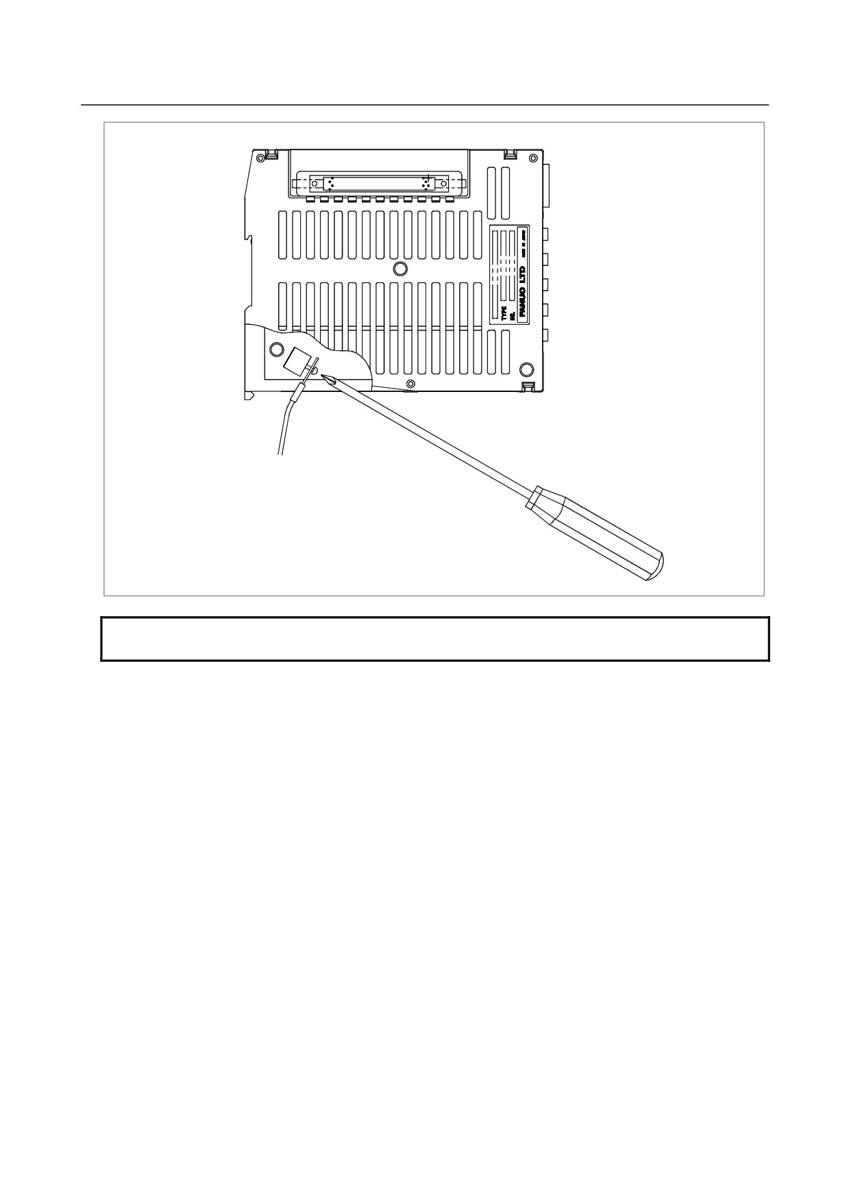
Secure the ground line to the ground terminal (GND) for signals of an analog input separate detector
interface unit, which is located at the bottom of the unit, with an M3 screw as shown in the figure below.
Connect the ground line to the ground plate of the cabinet.
- 104 -
B-64303EN/03
7.SERVO INTERFACE
GND
To ground plate of cabinet
NOTE
The torque with which a screw is tightened is 5 kgf⋅cm or less.
- 105 -
7.SERVO INTERFACE
B-64303EN/03
7.3.4
Analog Input Separate Detector Interface (Analog 1Vp-p
Interface)
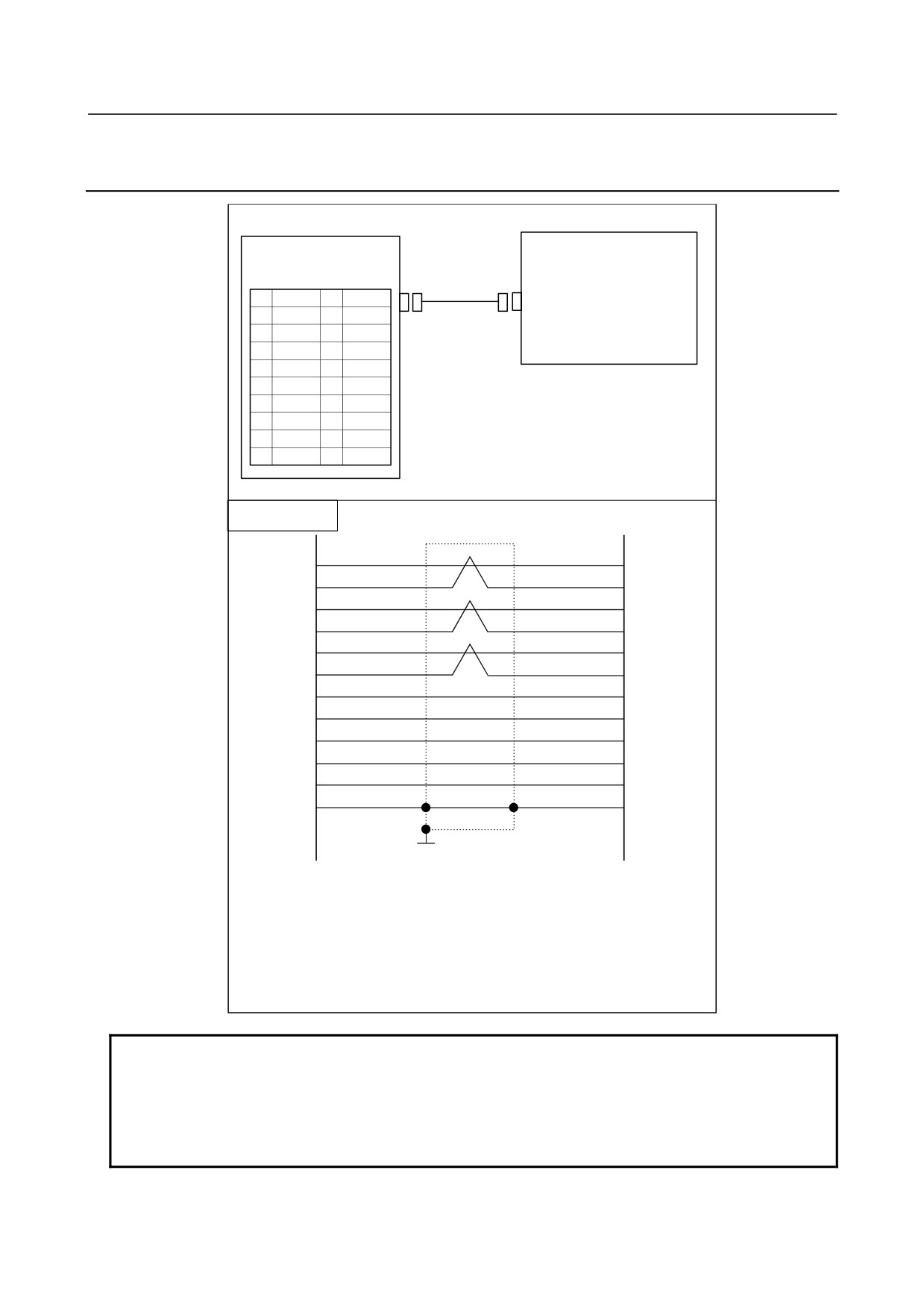
Analog Input Separate Detector Interface
Analog 1Vp-p output encoder
JF111 to F114
(PCR-EV20MDT)
1
PCA
11
NC
2
*PCA
12
0V
3
PCB
13
NC
4
*PCB
14
0V
5
PCZ
15
NC
6
*PCZ
16
0V
7
17
Leave NC (No Connection) open.
8
18
+5V
9
+5V
19
NC
10
20
+5V
Cable connection
1
PCA
PCA
2
*PCA
*PCA
3
PCB
PCB
*PCB
4
*PCB
5
PCZ
PCZ
6
*PCZ
*PCZ
9
+5V
+5V
18
+5V
+5V
20
+5V
+5V
12
0V
0V
14
0V
0V
Shielded drain wire
16
0V
FG
(Frame ground)
Shield
Ground plate
Recommended cable:
A66L-0001-0286 (#20AWG × 6 + #24AWG × 3-pair)
Recommended connectors:
PCR-E20FA (Honda Tsushin Kogyo)
FI30-20S (Hirose Electric)
FCN-247J020-G/E (Fujitsu)
52622-2011 (Molex)
FI40B-2015S (Hirose Electric)
NOTE
When supplementary descriptions other than warnings and notes are provided,
the above +5V signals can be used as the power supply of detectors.
In this case, the maximum current consumption per detector is 0.35 A.
Lower limit of the 5V signals:
4.95 V for the basic unit, and 4.9 V for the
additional unit
- 106 -