FANUC Series 0i-MODEL D, Series 0i Mate-MODEL D. CONNECTION MANUAL (HARDWARE) - page 2
B-64303EN/03
3.INSTALLATION
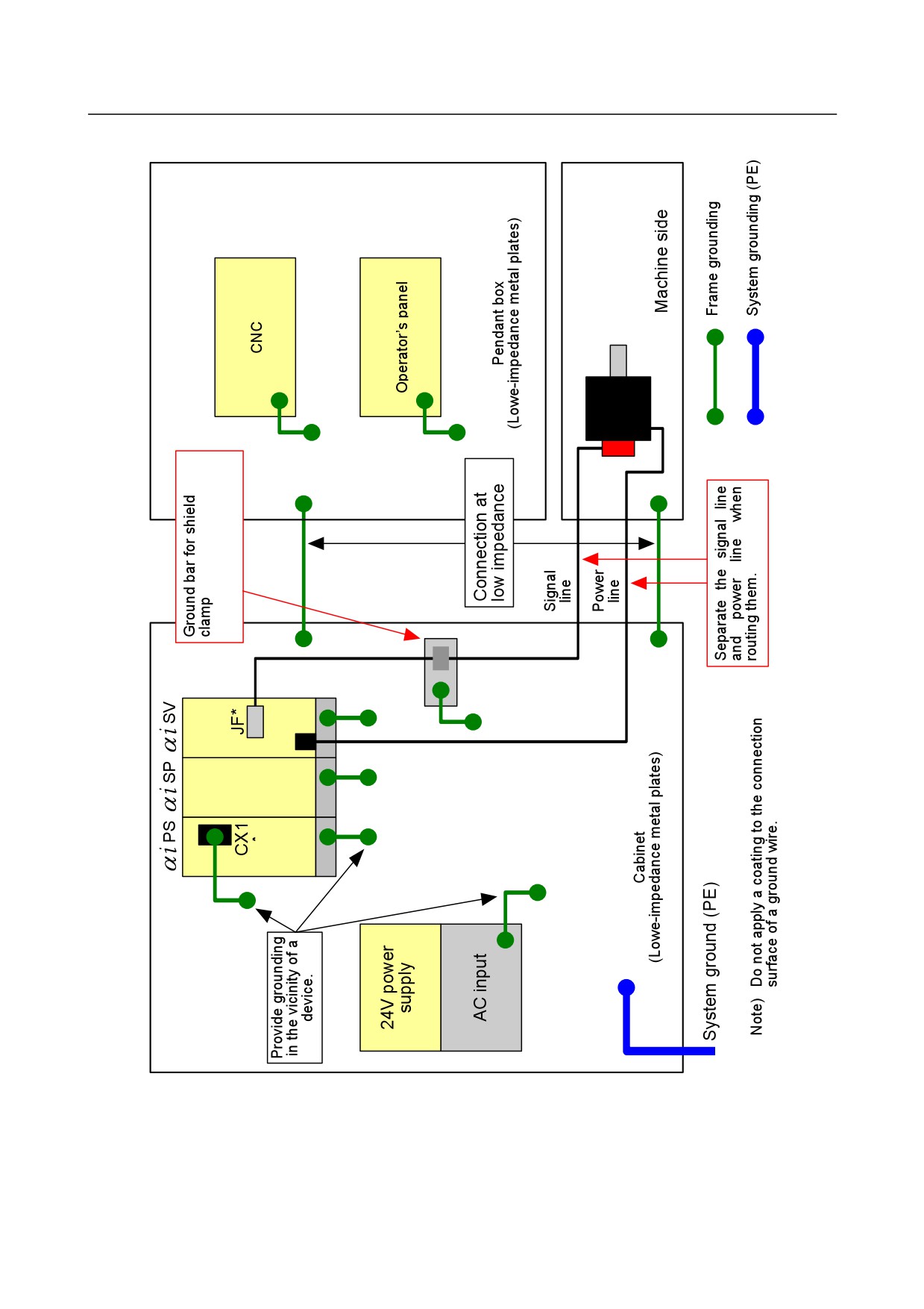
Fig. 3.5.1.2 (a) Schematic diagram for multipoint grounding scheme
- 17 -
3.INSTALLATION
B-64303EN/03
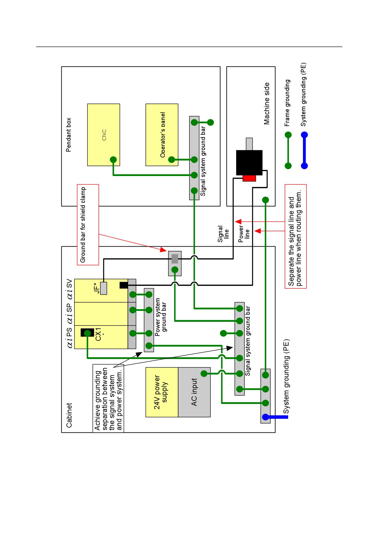
Fig. 3.5.1.2 (b) Schematic diagram for single-point grounding scheme
- 18 -
B-64303EN/03
3.INSTALLATION
3.5.1.3 Cable clamp and shield processing
Signal lines basically require shield clamps. The influence of external noise can be suppressed by
properly providing the signal lines with the shield clamps.
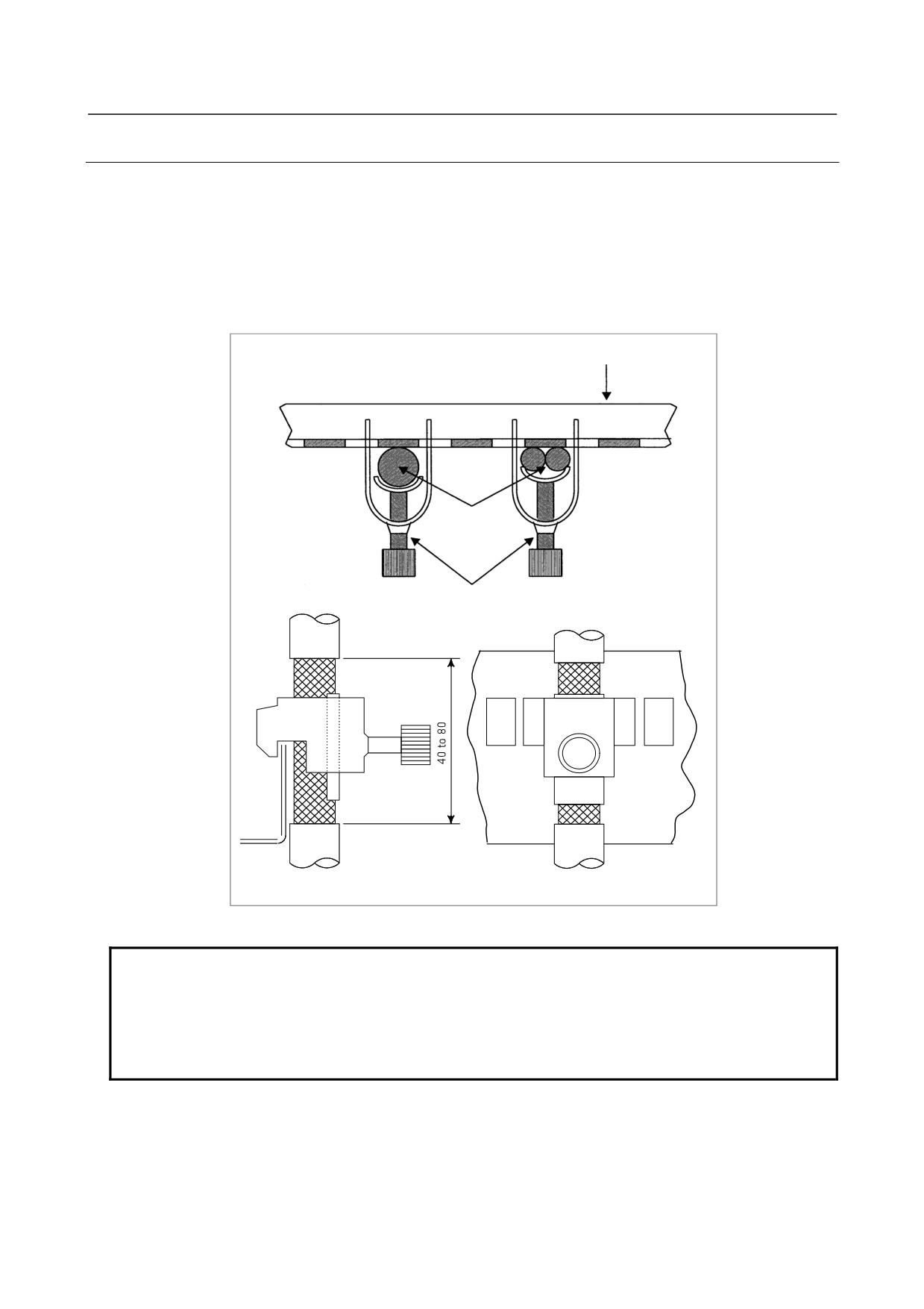
Partially peel the sheath off a cable and expose the shield, and press the exposed portion against the
ground bar with the clamp. Care should be taken so that the ground bar and shield have a surface contact
in a larger area. (See the figure below.)
When the multipoint grounding scheme is used, care should be taken so that the ground bar for the shield
clamp and cabinet are connected at low impedance by, for example, preventing the cabinet side contact
surface from being coated.
Ground plate
Cable
Metal fittings for
clamp
Fig. 3.5.1.3 (a) Cable clamp (1)
NOTE
Select a cable with a proper length.
If the cable is too long, the noise immunity may be reduced or noise may be
caused on other cables. In addition, when the excess length is coiled, the
inductance is increased and a high voltage is induced during turning on or off of
signals. This may cause a malfunction due to a failure or noise.
- 19 -
3.INSTALLATION
B-64303EN/03
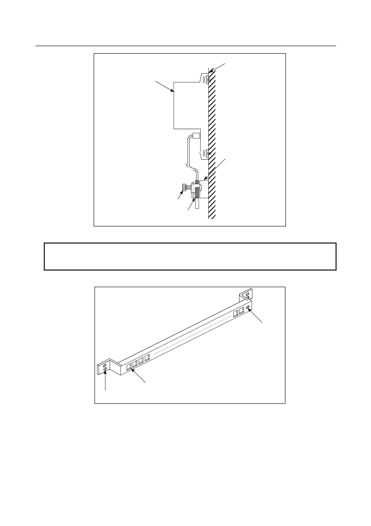
Machine side
installation board
Control unit
Ground plate
Metal fittings for
clamp
Shield cover
Fig. 3.5.1.3 (b) Cable clamp (2)
NOTE
Bundle the cables connected to a CNC or amplifier near each unit and shield
them.
Prepare ground plate like the following figure.
Ground terminal
(grounded)
Hole for securing
metal fitting clamp
Mount screw hole
Fig. 3.5.1.3 (c) Ground plate
For the ground plate, use a metal plate of 2 mm or thicker, which surface is plated with nickel.
- 20 -
B-64303EN/03
3.INSTALLATION
Ground plate
8
12
20
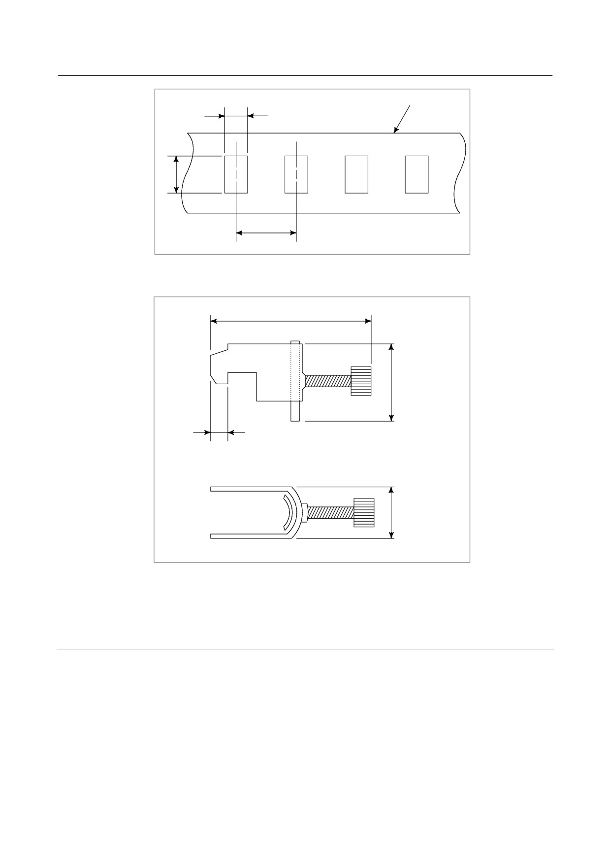
Fig. 3.5.1.3 (d) Ground plate holes
(Reference) Outer drawings of metal fittings for clamp.
Max. 55
28
6
17
Fig. 3.5.1.3 (e) Outer drawings of metal fittings for clamp
Ordering specification for metal fittings for clamp
A02B-0124-K001 (8 pieces)
3.5.1.4 Cabinet
A cabinet is an important element in improving noise immunity and suppressing radiated noise. One of
the causes of problems related to noise immunity and radiated noise is faulty electrical continuity between
the metal plates that make up the cabinet. Typically, noise that becomes a problem is high-frequency
noise, against which measures must be taken in the cabinet design.
(1) Basic cabinet structure
A cabinet should basically be made of metal.
To improve noise immunity, there must be low-impedance electrical continuity between the metal
plates that make up the cabinet, which are the side plates, top plate, and bottom plate, and a
welding-type cabinet structure is recommended.
- 21 -
3.INSTALLATION
B-64303EN/03
As for a cabinet welding method, bead welding is more suitable than spot welding for providing
low-impedance electrical continuity between the metal plates.
For an assembly-type cabinet structure, provide electrical continuity by bringing the metal plates
into direct contact with each other, without applying a coating to their joint surface areas.
In a structure that has the metal plates connected only with wires because of structural constraints,
low-impedance connections are more difficult to make than in a structure in which welding is made
or the metal plates are brought into direct contact with each other. It is necessary to maintain
sufficient levels of items such as the cross-sectional area of a wire to use, continuity of connections,
and contact areas.
Bead welding
Bring the metal plates into direct contact with each
other, without applying a coating to their joint areas.
NOTE
For improved noise immunity, how to provide low-impedance electrical continuity
in the cabinet is described here. To construct a protective circuit, a protective
grounding connection must be made between the metal plates by using electric
wires with a cross-sectional area appropriate for the AC input power capacity of
the unit mounted on each metal plate.
(2) Mounting units on the cabinet
The shortest possible lengths of unit ground wires should be used to make connections. A ground
wire with a small conductor diameter causes impedance to high-frequency noise to become
particularly higher, leading to an insufficient grounding effect. For the location of the ground
terminal of each unit, refer to the manual relevant to the unit. The following shows the
recommended method by which the metal plate with the unit mounted is installed on the cabinet.
Care should be taken so that the cabinet and metal plate are connected to each other on their broad
areas with no coating. It is not recommended that electrical continuity be provided only by screws,
because impedance to high frequency cannot be sufficiently low.
- 22 -
B-64303EN/03
3.INSTALLATION
<Good example>
Cabinet
Metal
plate
Unit
Shortest connection
Continuity on areas with
with thick ground wire
no coating
<Bad example>
Cabinet
Metal
plate
Unit
Continuity only by
Thin ground wire,
screw in a coated area
long ground wire
3.5.2
Connecting the Ground Terminal of the Control Unit
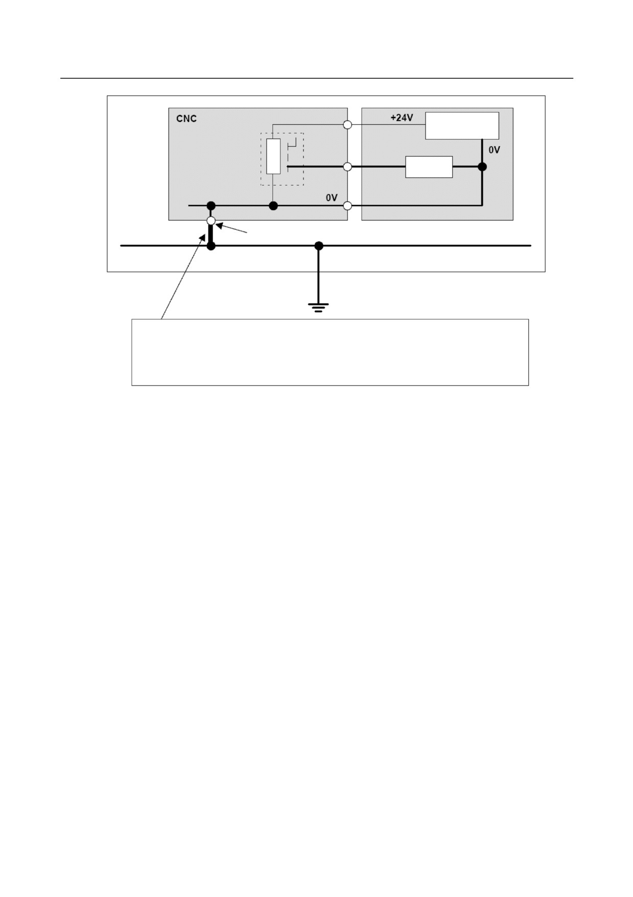
Connecting the 0 V output in the CNC to a protective circuit (ground)
The IEC 204-1 and JIS B 6015 standards specify the following:
- Protection against malfunctions due to ground faults
“To make the control circuit prevent malfunctions of a machine tool due to a ground fault and not to
prevent the machine tool from stopping, either of the ground and electronic circuits shall be connected to
a protective circuit.”
Note that for each FANUC CNC, the 0V output in the CNC is connected to a protective circuit (ground).
- 23 -
3.INSTALLATION
B-64303EN/03
Machine
24 VDC power
supply
Power
magnetics
Output
cabinet
signal
Relay
NC ground terminal
Machine protective circuit (ground) network
Connection to the ground in the user factory
This bold line indicates grounding for the control unit described in the connection manual.
As shown in this figure, by just connecting the ground terminal of the control unit to the machine ground,
the 0 V output of the relay circuit in the power magnetics cabinet is connected to the ground (protective
circuit).
- 24 -
B-64303EN/03
3.INSTALLATION
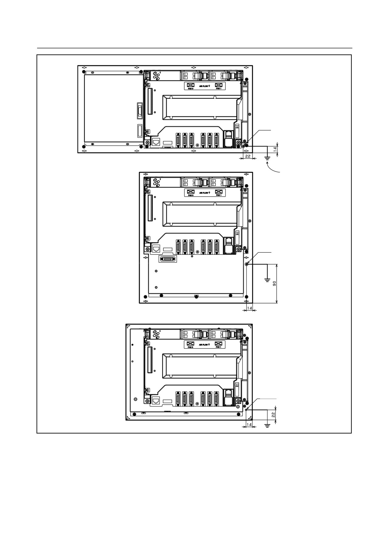
For the 8.4" LCD/MDI (horizontal) type
Unit back face
M4 screw
For the 8.4" LCD/MDI (vertical) type
Grounding cable
Unit back face
M4 screw
For the 10.4" LCD type
Unit back face
M4 stud
Connect the 0V line in the control unit to the ground plate of the cabinet via the protective ground
terminal (shown in the above figure).
For the locations of the ground terminals of the other units, see the external dimensions of each unit in the
appendix.
- 25 -
3.INSTALLATION
B-64303EN/03
3.5.3
Separating Signal Lines
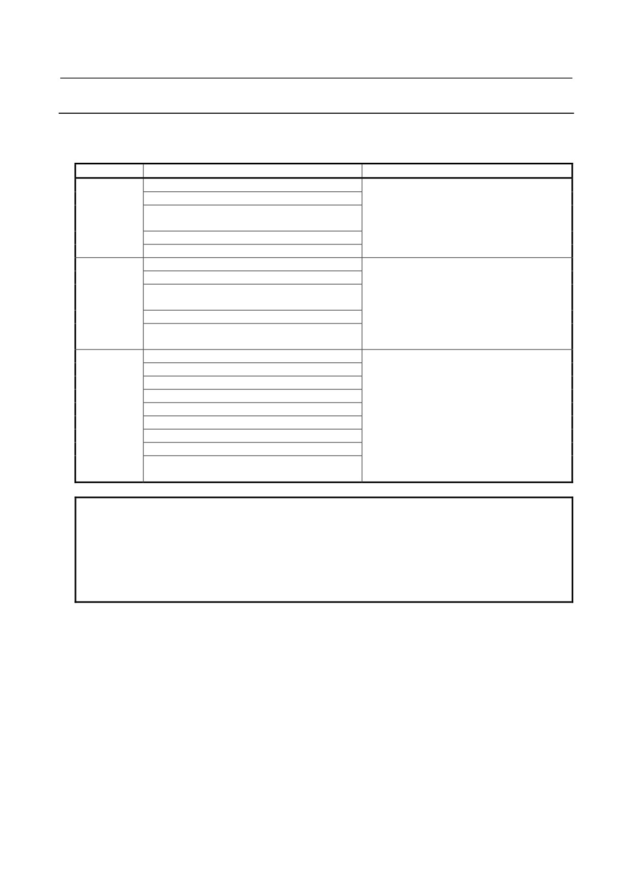
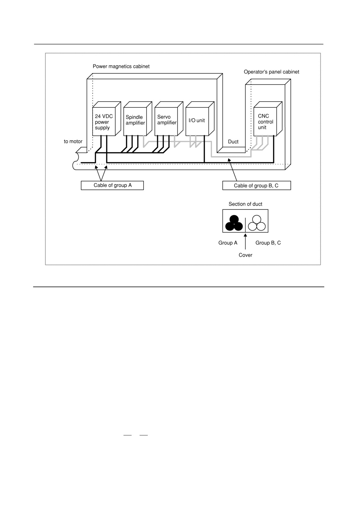
The cables used for the CNC machine tool are classified as listed in the following table.
Process the cables in each group as described in the action column.
Group
Signal line
Action
A
Primary AC power line
Bind the cables in group A separately (Note 1)
Secondary AC power line
from groups B and C, or cover group A with an
AC/DC power lines (containing the power lines for
electromagnetic shield (Note 2).
the servo and spindle motors)
See Subsection 3.5.4 and connect spark killers
AC/DC solenoid
or diodes with the solenoid and relay.
AC/DC relay
B
DC solenoid (24 VDC)
Connect diodes with the DC solenoid and relay.
DC relay (24 VDC)
Bind the cables in group B separately from
DI/DO cable between the I/O unit and power
group A, or cover group B with an
magnetics cabinet
electromagnetic shield.
DI/DO cable between the I/O unit and machine
Separate group B as far from group C as
24 VDC input power cables connected to the
possible.
control unit and its peripherals
It is desirable to perform shield processing.
C
Cable between the CNC and I/O unit
Bind the cables in group C separately from
Cable for position and velocity feedback
group A, or cover group C with an
Cable between the CNC and spindle amplifier
electromagnetic shield.
Cable for the position coder
Separate group C as far from group B as
Cable for the manual pulse generator
possible.
Be sure to perform shield processing as
Cable between the CNC and the MDI (Note 3)
described in Subsection 3.5.5.
RS-232C and RS-422 interface cable
Cable for the battery
Other cables for which shield processing is
specified
NOTE
1 Binding the cables in one group separately from another means that the groups
are placed 10 cm or more apart from one another.
2 Covering a group with an electromagnetic shield means that shielding is
provided between groups with grounded steel plates.
3 The shield is not required when the cable between the CNC and MDI is no more
than 30 cm in length.
- 26 -
B-64303EN/03
3.INSTALLATION
3.5.4
Noise Suppressor
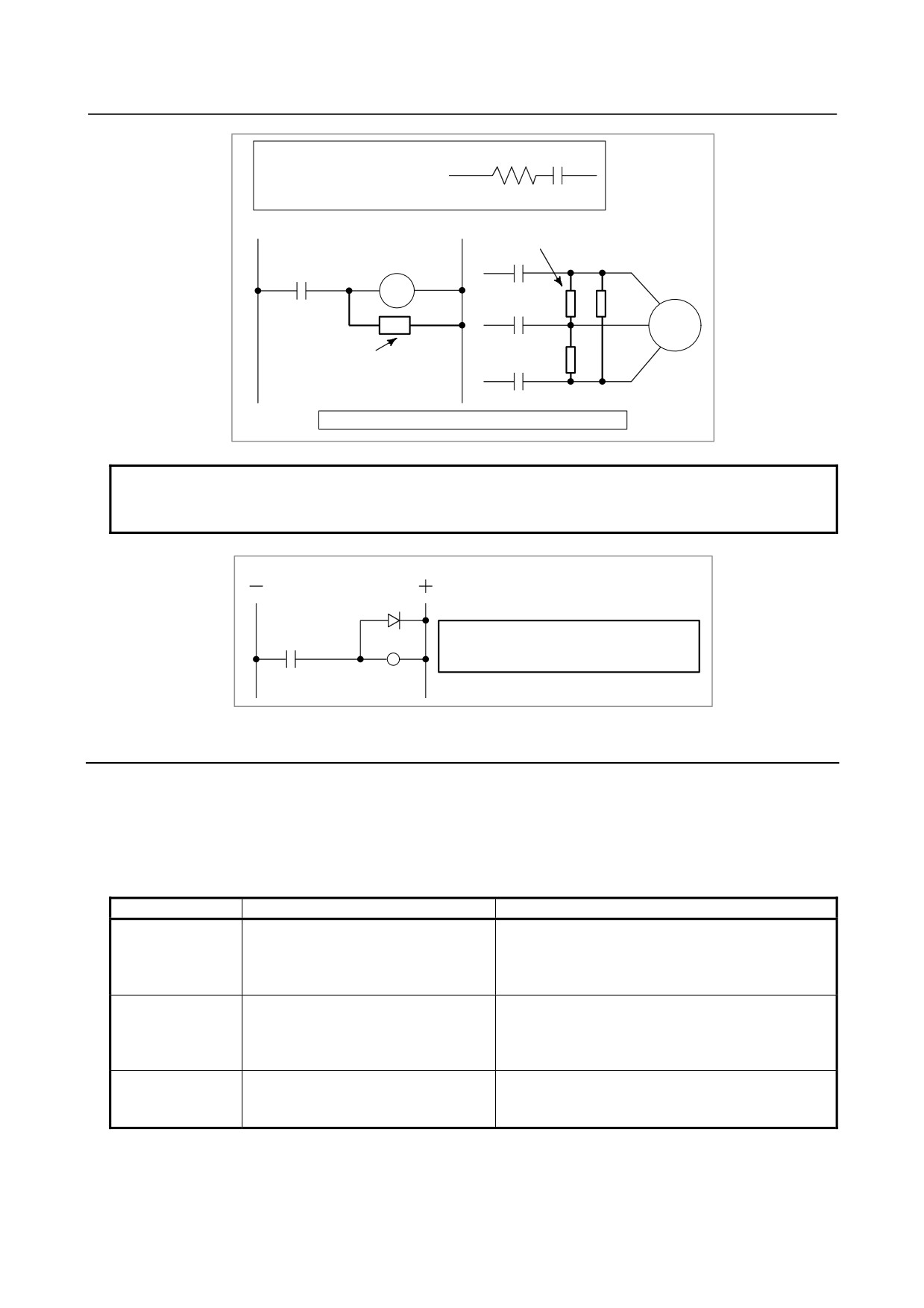
The AC/DC solenoid, AC/DC relay, and other devices are used in the power magnetics cabinet.
A high pulse voltage is caused by coil inductance when these devices are turned on or off.
This pulse voltage is induced through a cable or any other component, causing the electronic circuits to be
disturbed.
Take the following measures against the pulse voltage:
1)
See Subsection 3.5.3 for groups A and B, and use spark killers for AC circuits or diodes for DC
circuits.
2)
See “Notes on selecting the spark killer” below for information about selection of spark killers or
diodes.
Notes on selecting the spark killer
• Use a CR-type spark killer. (Use it for AC circuits.)
(A varistor is useful in clamping the peak pulse voltage, but cannot suppress the sudden rise of the
pulse voltage. FANUC therefore recommends the use of a CR-type spark killer.)
• The reference CR values of the spark killer shall conform to the following based on the current ((I
(A)) and DC resistance of the coil in the stationary state:
1)
Resistance (R)
: Equivalent of the DC resistance of the coil
2
2
I
I
2)
Capacitance (C) :
~
(μF)
10
20
I
:Current of the coil in the stationary state [A]
- 27 -
3.INSTALLATION
B-64303EN/03
R
C
Equivalent circuit of the spark killer
Spark killer
AC relay
Motor
Spark killer
Mount the noise eliminator near a motor or a relay coil.
NOTE
Use a CR-type noise eliminator. Varistor-type noise eliminators clamp the peak
pulse voltage but cannot suppress a sharp rising edge.
Diode (used for direct-current circuits)
Diode
Use a diode which can withstand a voltage up
DC relay
to two times the applied voltage and a current
up to two times the applied current.
3.5.5
Measures Against Surges due to Lightning
To protect equipment from surge voltages caused by lightning, install a lightning surge protector between
lines and between a line and ground. For how to install protectors, see Appendix A "FITTING A
LIGHTNING SURGE PROTECTION DEVICE" in FANUC SERVO AMPLIFIER αi series
DESCRIPTIONS (B-65282EN).
Lightning surge protector specifications
Ordering number
Specification
Remarks
For line-to-line installation:
Manufactured by Okaya Electric Industries Co., Ltd.
RAV-781BYZ-2
A06B-6077-K142
For 200VAC line
For line-to-ground installation:
TÜV approved products
RAV-781BXZ-4
For line-to-line installation:
Manufactured by Okaya Electric Industries Co., Ltd.
RAV-152BYZ-2A
A06B-6077-K143
For 400VAC line
For line-to-ground installation:
TÜV approved products
RAV-801BXZ-4
Integration type for line-to-line
Manufactured by Okaya Electric Industries Co., Ltd.
A06B-6077-K144
installation/line-to-ground installation:
For 200VAC line
RCM-601BUZ-4
TÜV approved products
* The line-to-line or line-to-ground installation type (A06B-6077-K144) and the integration type
(A06B-6077-K142) are equivalent in performance and specifications.
- 28 -
B-64303EN/03
3.INSTALLATION
3.6
CONTROL UNIT
3.6.1
Installation of the Control Unit
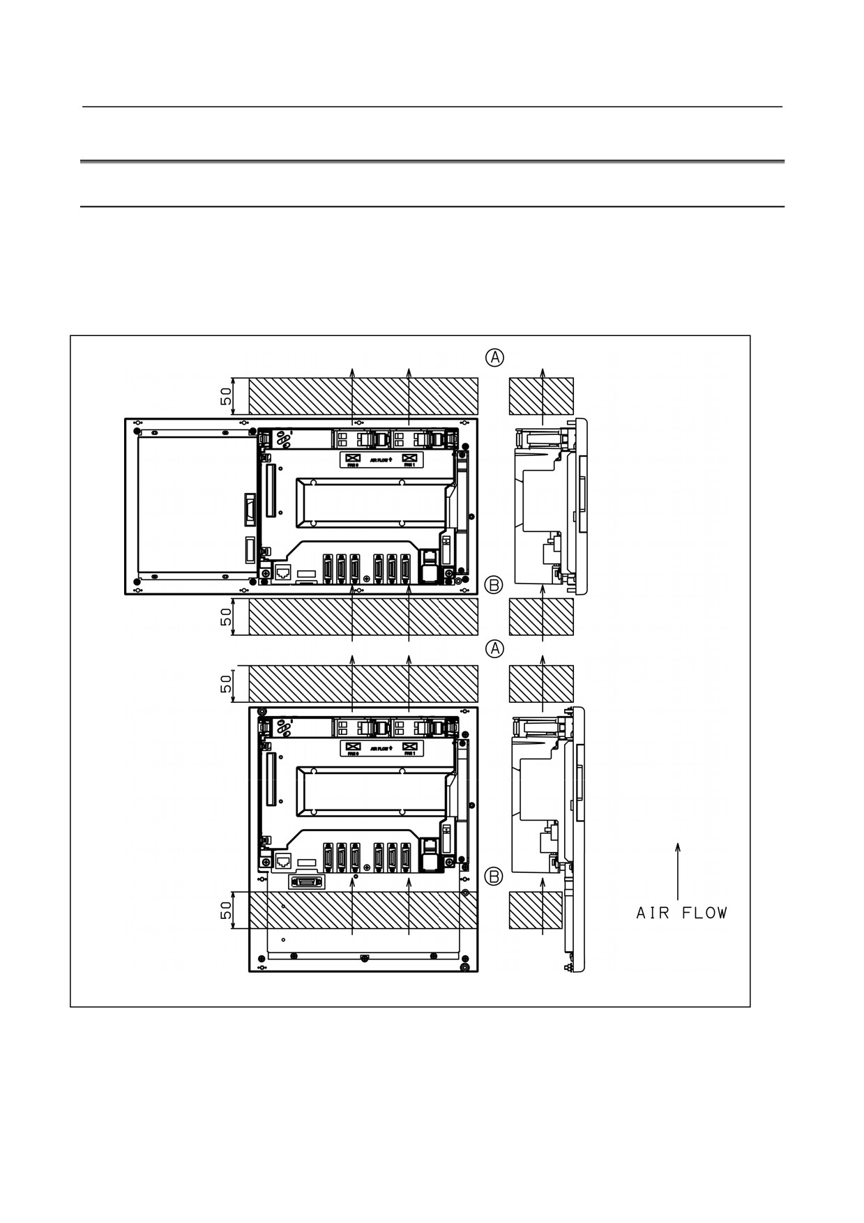
The control unit has a built-in fan motor.
Air enters the control unit through the bottom and is drawn through the fan motor which is located on the
top of the control unit.
Space (A), shown in Fig. 3.6.1, must be provided to ensure unrestricted air flow. Also, space (B) should
be provided whenever possible. When space (B) cannot be provided, ensure that nothing is placed in the
immediate vicinity which could obstruct the air flow.
For a horizontal unit
For a vertical unit
Unit : mm
Fig. 3.6.1
- 29 -
3.INSTALLATION
B-64303EN/03
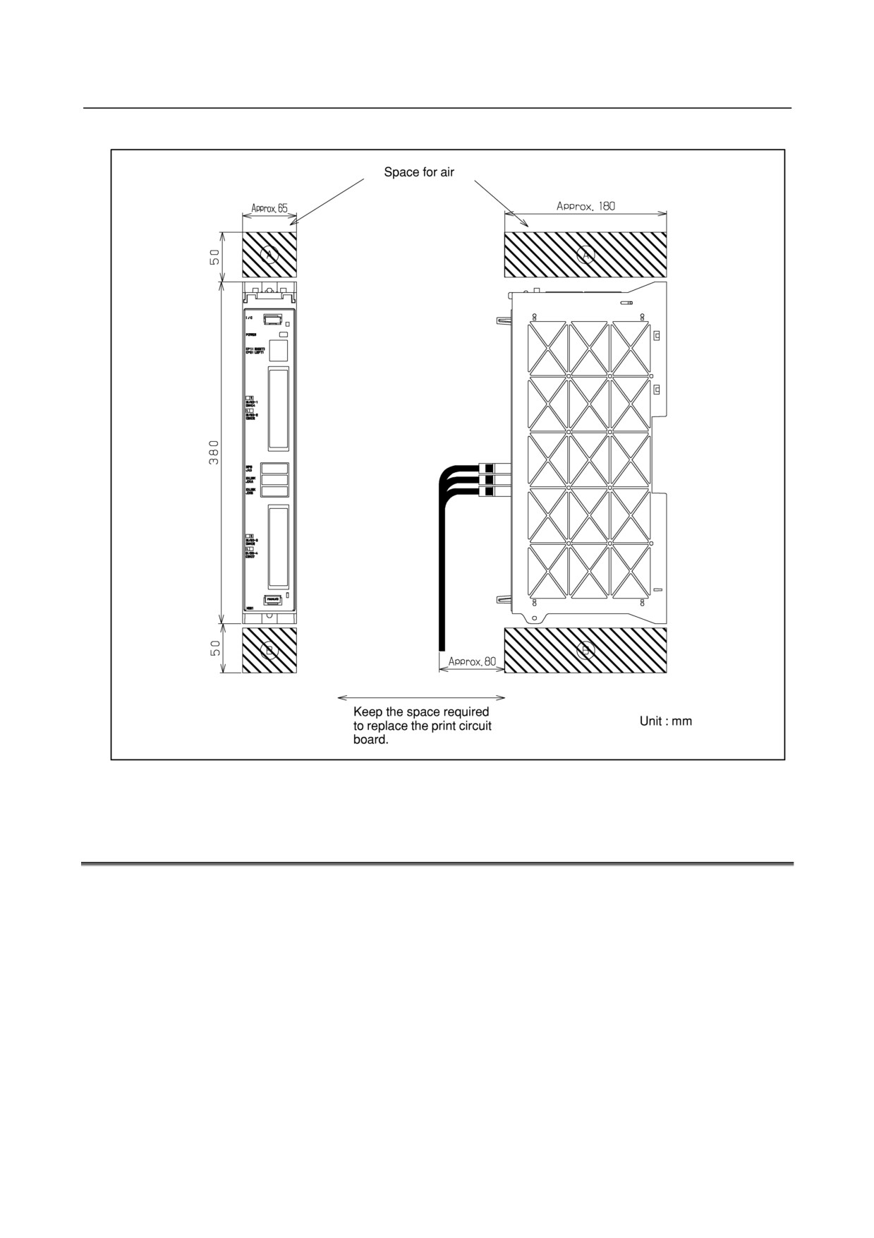
Installing the I/O unit for 0i
Fig. 3.6.2
3.7
SEVERE DUST/LIQUID PROTECTION OF CABINETS AND
PENDANT BOXES
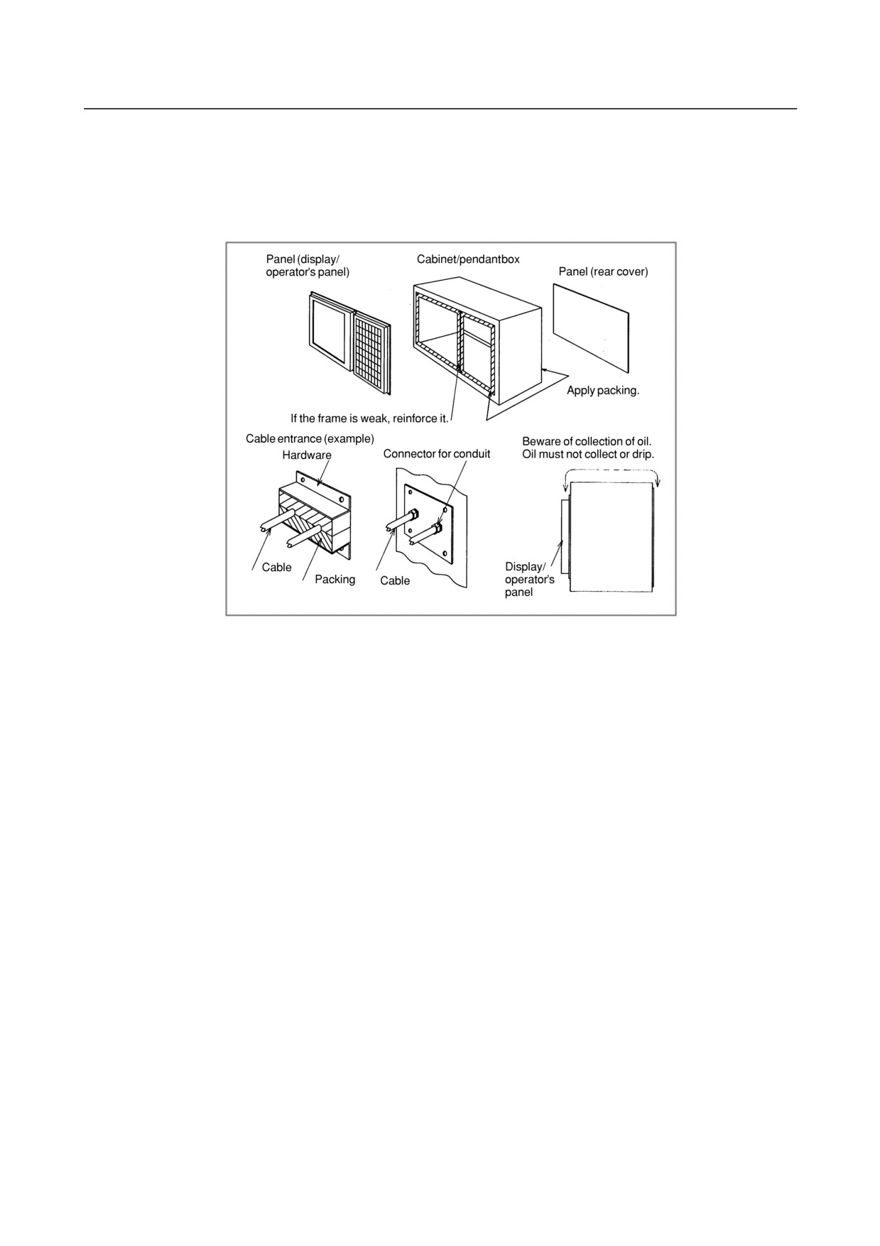
Since a cabinet or pendant box, which is designed by the machine tool builder, for housing display units
or operator's panels is likely to receive dust particles, chippings, or greasy fumes, so keep the following in
mind to keep them out.
1)
The cabinet and pendant box must be of a hermetically sealed structure.
2)
Apply packing to the panel mounting surface to which a display and operator's panel are to be
mounted.
Apply packing to the panel mounting surfaces of other units mounted on the same case for
dust/liquid protection.
3)
Make sure that the door packing of the cabinet and pendant box is sealed firmly.
4)
For a cabinet or pendant box with a rear cover, apply packing to the mounting surface.
5)
Make sure that the cable entrance is sealed with packing, connectors for conduits, etc.
6)
Make sure that all other openings are blocked, if any.
7)
Make sure that the display and operator's panel do not receive cutting debris and coolant directly.
- 30 -
B-64303EN/03
3.INSTALLATION
8)
Since coolant accumulated on the top of a cabinet or pendant box may drip onto the panel surface of
a display unit of operator's panel, use a structure that prevents coolant from being accumulating on
the top or from being dripping onto the panel surface. For example, install a canopy over a display
unit or operator's panel.
9)
The front surface of a display unit must be vertical. Otherwise, coolant is likely to accumulate in
the lower part of the display screen.
- 31 -
4.POWER SUPPLY CONNECTION
B-64303EN/03
4 POWER SUPPLY CONNECTION
4.1
GENERAL
This chapter explains the connection of power supply for control unit.
4.2
TURNING ON AND OFF THE POWER TO THE CONTROL
UNIT
4.2.1
Power Supply for the Control Unit
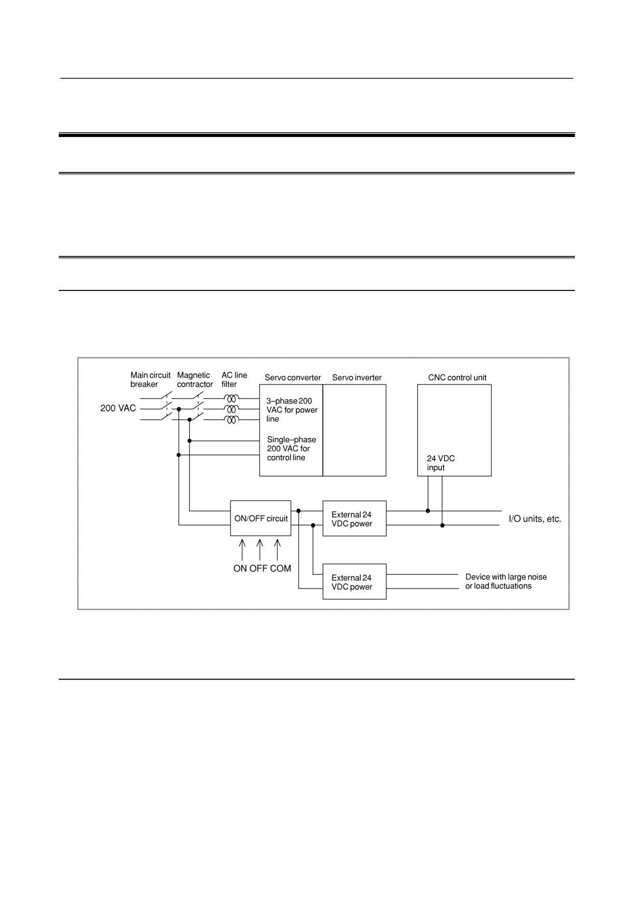
Supply power (24VDC) to the control unit from an external sources.
Provide an ON/OFF circuit for turning the AC power on and off outside the unit as shown in Fig. 4.2.1.
To minimize the effect of noise or voltage fluctuations to the CNC, it is recommended that a power to the
CNC be provided independently of the power sources to devices with large noise or load fluctuations.
Fig. 4.2.1
4.2.2
External 24 VDC Power Specification and Circuit
Configuration
Specifications of recommended external 24 VDC power supply (regulated power supply):
(The power
supply must satisfy UL1950.)
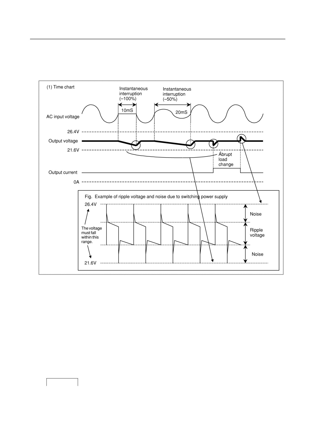
Output voltage:
+24 V ±10% (21.6 V to 26.4 V)
(including ripple voltage and noise. See the figure below.)
Output current:
The continuous load current must be larger than the current consumption of the CNC.
(At the maximum temperature inside the power magnetics cabinet in which the power supply is
located)
- 32 -
B-64303EN/03
4.POWER SUPPLY CONNECTION
Load fluctuations (including rush current):
The output voltage must not go out of the above range due to load fluctuations by external DO and
other factors.
Instantaneous input interruption retention time:
10 ms (for -100%), 20 ms (for -50%)
Fig 4.2.2 (a) Timing chart
-
Notes to take when the vertical axis exists
When the vertical axis exists, select the DC power supply that has a long voltage hold time to decrease
the amount of vertical axis falling during power-off (including a power failure).
If the operating voltage drops to less than or equal to
21.6V, the CNC releases servo activation.
Therefore, when the hold time for 24 VDC during AC power-off is too short, servo activation is released
before the breaks are applied because some peripheral circuit detects power-off. This may increase the
amount of vertical axis falling.
Generally, a power supply with sufficient power capacity tends to increase the hold time during
power-off.
-
Circuit configurations
The following circuit configurations are not recommended.
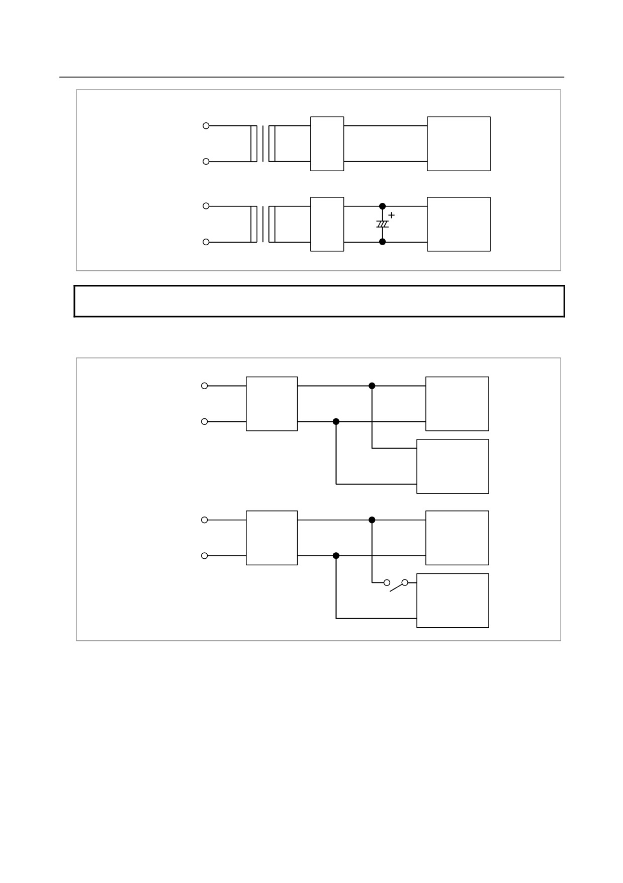
Forbidden
<1> Circuit examples that cannot retain the output voltage at an instantaneous interruption (the voltage
reduces to 21.6 V or below)
- 33 -
4.POWER SUPPLY CONNECTION
B-64303EN/03
Example 1
Rectifier
circuit
AC input
CNC unit
Example 2
Rectifier
circuit
AC input
CNC unit
NOTE
The rectifier circuit means a circuit using diodes for full-wave rectification.
<2> Circuit examples that exceed the output voltage specifications (21.6 V to 26.4 V) due to an abrupt
load change
Example 1
Regulated
AC input
power supply
CNC unit
Device with
remarkable load
fluctuations
Example 2
Regulated
AC input
power supply
CNC unit
Device with large
rush current
For a circuit configuration in <2>, connect another regulated power supply to be specifically used for the
device with remarkable load fluctuations so that the CNC and other units are not affected.
Avoid the use of a configuration in <2> if possible, even in an environment with small load fluctuations
or rush current. When two or more units are connected to the same power supply, the 24-VDC power
may not be turned on due to a failure in a unit other than the CNC. If this happens, it takes much time to
locate the failure because the CNC cannot start and no alarm indication is provided.
When the CNC and other units are connected to the same power supply because of limited space for the
power magnetics cabinet or for some other reason, careful consideration must be given to possible rush
currents and voltage fluctuations. In addition, to prevent power supply noise from entering the CNC, a
noise filter must be inserted before the power to the CNC.
(Recommended noise filter: ZGB2203-01U
manufactured by TDK)
- 34 -
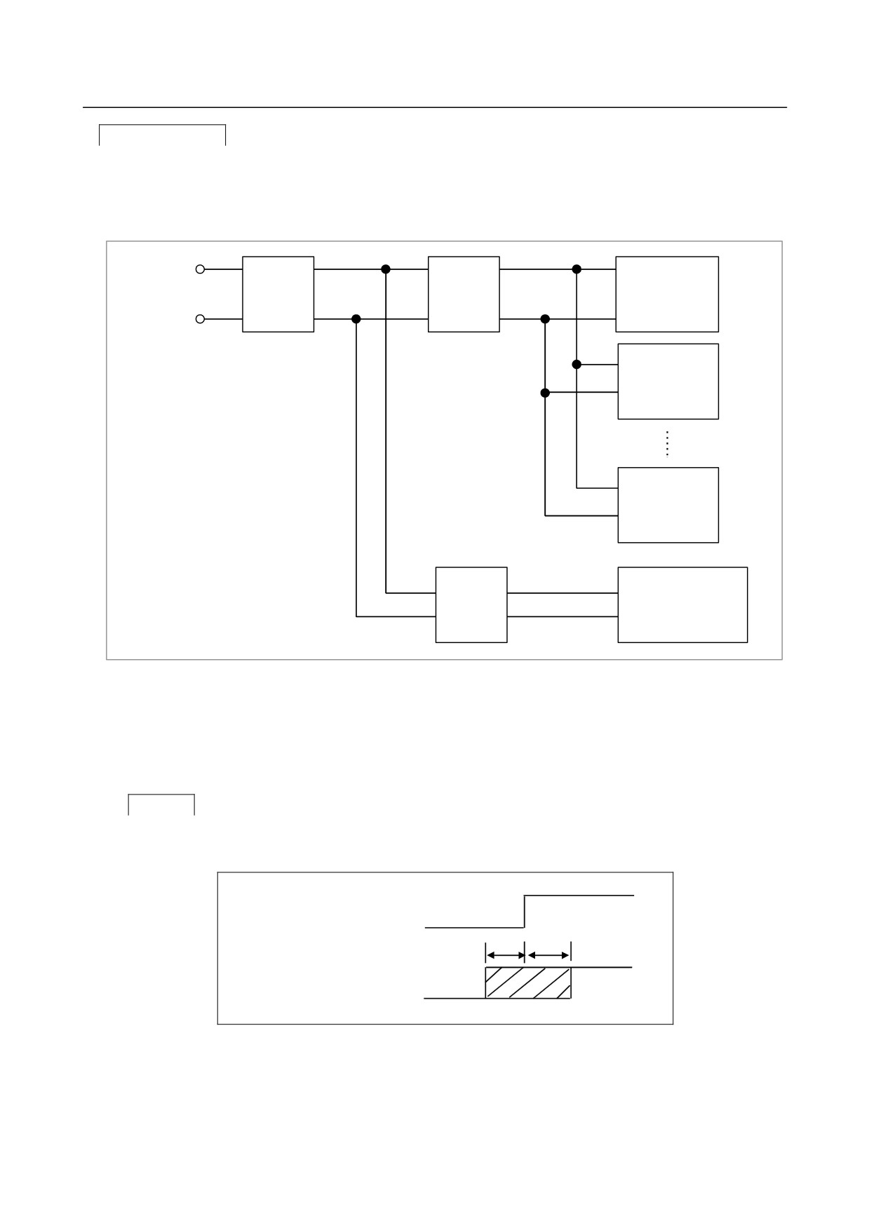
B-64303EN/03
4.POWER SUPPLY CONNECTION
Recommended
The following circuit configuration is recommended.
The power to the CNC and other, FANUC Servo Unit β series with an I/O link (β amplifier with an I/O
link), and so on in the sample configuration below) is assumed to be turned on or off at the same time.
(The power to any unit is not assumed to be turned on during operation or before the power to the CNC is
turned on.
On/off
Regulated
AC input
circuit
power
CNC unit
supply
I/O Unit-A
β amplifier with
an I/O link
Regulated
Device with large noise
power
or load fluctuations
supply
Fig 4.2.2 (b)
For example, the following units require 24VDC power sources.
• Various I/O Link slave units
• β servo amplifier and βi servo amplifierβ
• Separate detector unit
Caution
Turning the power to units on simultaneously when turning the power to the CNC:
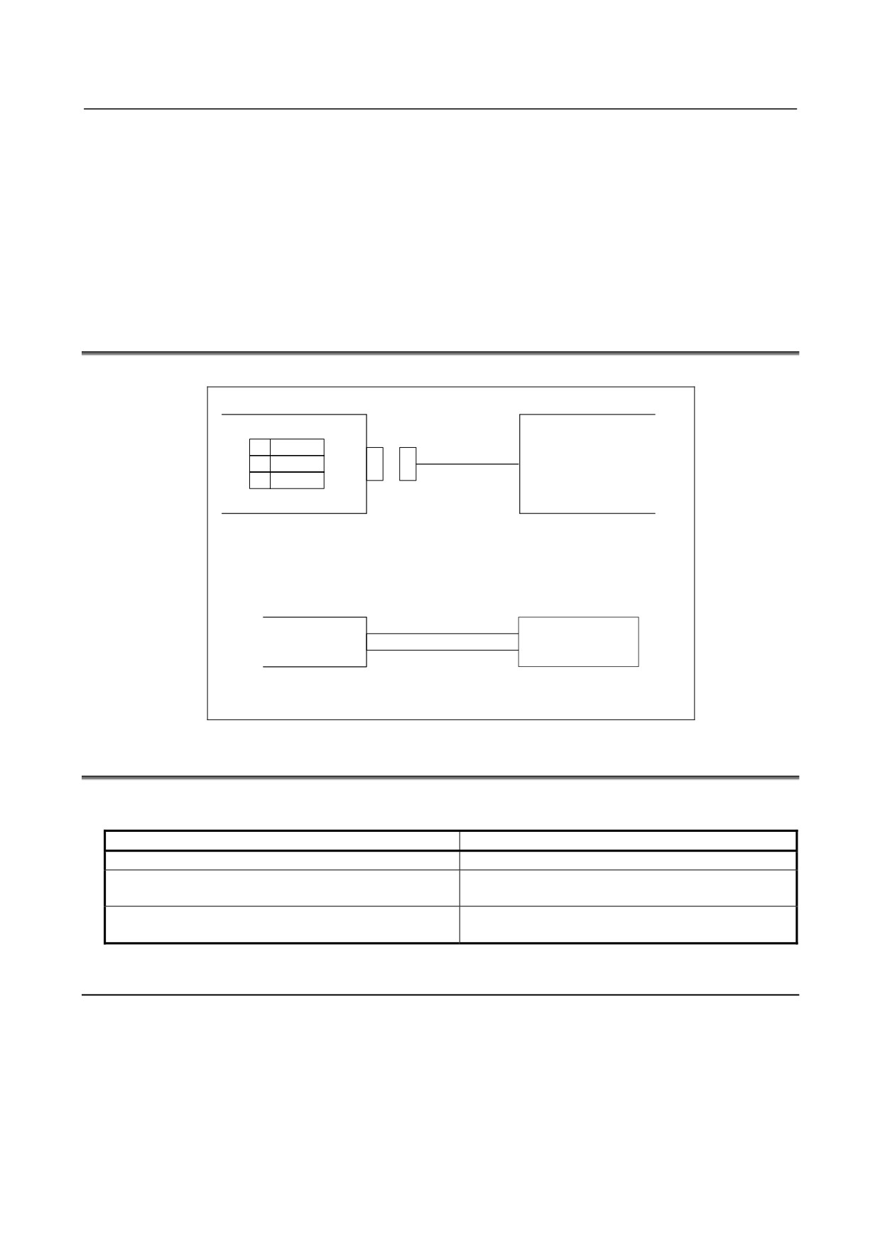
When the following power-on timing condition is satisfied, the power to units is assumed to be turned on
simultaneously when the power to the CNC is turned on.
On
Power to the CNC
Off
t1
t2
Power to units
On
(including the Power
Mate)
Off
t1:200ms Means that the power to units (including the Power Mate) is turned on within 200 ms before
the power to the CNC is turned on.
t2:-500ms Means that the power to units (including the Power Mate) is turned on within 500 ms after
the power to the CNC is turned on.
- 35 -

4.POWER SUPPLY CONNECTION
B-64303EN/03
Turning the power to units off simultaneously when turning the power to the CNC off:
This means that the power to units may be turned off within 500 ms before the power to the CNC control
unit is turned off. If the power to units is turned off earlier, alarm information is left in the NC.
On
Power to the CNC
Off
t1
t1:500ms Means that the power to units are turned off within 500 ms before the power to the CNC is
turned off.
The power to the CNC must not be turned on or off with the power to units on.
4.2.3
Power-on Sequence
Turn on the power to all the units at the same time, or in the following sequence:
1 Power to the overall machine (200 VAC)
2 Servo amplifier control power supply (200 VAC)
3 Power to the slave I/O units connected via the I/O link, the separate detector interface unit, and the stand-alone
type LCD unit (24 VDC), power to the CNC controller (24 VDC), power to the separate detector (scale)
“Turning on the power to all the units at the same time” means completing the power-on operations in 1
and 2 above within 500 ms of performing power-on in 3.
Do not remove the memory backup battery (3VDC) and the separate absolute pulse coder battery (6VDC)
regardless of whether the power of the CNC controller is on or off. If the batteries are removed when
the CNC controller is off, the parameters and programs saved in the CNC controller and the position data
in the pulse coder are lost.
For information on replacing the memory backup battery, see Subsection 4.4.1.
4.2.4
Power-off Sequence
Turn off the power to all the units at the same time, or in the following sequence:
1 Power to the slave I/O units connected via the I/O link, the separate detector interface unit, and the CNC
controller (24 VDC)
2 Servo amplifier control power supply (200 VAC), power to the separate detector (scale)
3 Power to the overall machine (200 VAC)
When turning off the power of the CNC controller, be sure to turn off the power of units such as the slave
I/O devices connected through I/O Link, β amplifier with I/O Link, Power Mate and separate detector
interface unit, control power supply of the servo amplifier, and separate detector (such as a scale).
“Turning off the power to all units at the same time” means completing the power-off operations in 2 and
3 above within 500 ms before the power-off operation described in 1 above. If the power to the units
indicated in 2 or 3 is turned off other than within 500 ms of the power in 1 being turned off, alarm
information is left in the NC.
When the power is turned off or when the power is momentarily disconnected, processing must be
performed from the machine as necessary, because motor control is disabled.
For example, when movement along a vertical axis is controlled, a brake should be applied to prevent
falling. Usually, the brake clamps the motor when the servo is not activated or when the motor is not
turning. The clamp is released only when the motor is turning.
- 36 -
B-64303EN/03
4.POWER SUPPLY CONNECTION
When servo axis control is disabled by power-off or momentary power disconnection, the brake usually
clamps the servo motor. In this case, before the relay for clamping operates, the controlled axis may fall.
So, also consider whether the distance the axis is likely to fall will cause a problem.
When the power is turned off:
Be sure to apply a brake for clamping before turning off the power to CNC.
When the power fails:
If a power failure is detected, a brake must be applied immediately. Select the power supply with a
longer DC power retention time after AC power-off, because the servo is deactivated if the power to
CNC is turned off.
4.3
CABLE FOR POWER SUPPLY TO CONTROL UNIT
Supply the power to the control unit from an external 24 VDC power supply.
CNC control unit
External power
CP1
1
+24V
24VDC stabilized
2
0V
power
3
24VDC ±10%
Cable
CP1
AMP Japan
1-178288-3 (housing)
1-175218-5 (Contact)
External power
Select a source that
+24V (1)
meets the external
0V (2)
power terminal.
Recommended cable : A02B-0124-K830(5m)
(Crimp terminal of size M3 is available on the external power side)
4.4
BATTERIES
In a system using this CNC, batteries are used as follows:
Use
Component connected to battery
Memory backup in the CNC control unit
CNC control unit
Preservation of the current position indicated by the
Separate detector interface unit
separate absolute pulse coder
Preservation of the current position indicated by the
Servo amplifier
absolute pulse coder built into the motor
4.4.1
Battery for Memory Backup in the CNC Control Unit (3 VDC)
Offset data, and system parameters are stored in SRAM in the control unit. The power to the SRAM is
backed up by a lithium battery mounted on the front panel of the control unit. The above data is not lost
even when the main battery goes dead. The backup battery is mounted on the control unit at shipping.
This battery can maintain the contents of memory for about a year.
When the voltage of the battery becomes low, alarm message "BAT" blinks on the display and the battery
alarm signal is output to the PMC. When this alarm is displayed, replace the battery as soon as possible.
In general, the battery can be replaced within two or three weeks, however, this depends on the system
configuration.
- 37 -
4.POWER SUPPLY CONNECTION
B-64303EN/03
If the voltage of the battery becomes any lower, memory can no longer be backed up. Turning on the
power to the control unit in this state causes system alarm to occur because the contents of memory are
lost. Clear the entire memory and reenter data after replacing the battery.
FANUC thus recommends that the battery be replaced periodically, once a year, regardless of whether a
battery alarm is issued.
The following two kinds of batteries can be used.
• Lithium battery built into the CNC control unit.
• Two alkaline dry cells (size D) in the external battery case.
NOTE
A lithium battery is installed as standard at the factory.
When a lithium battery is used
- Replacement procedure
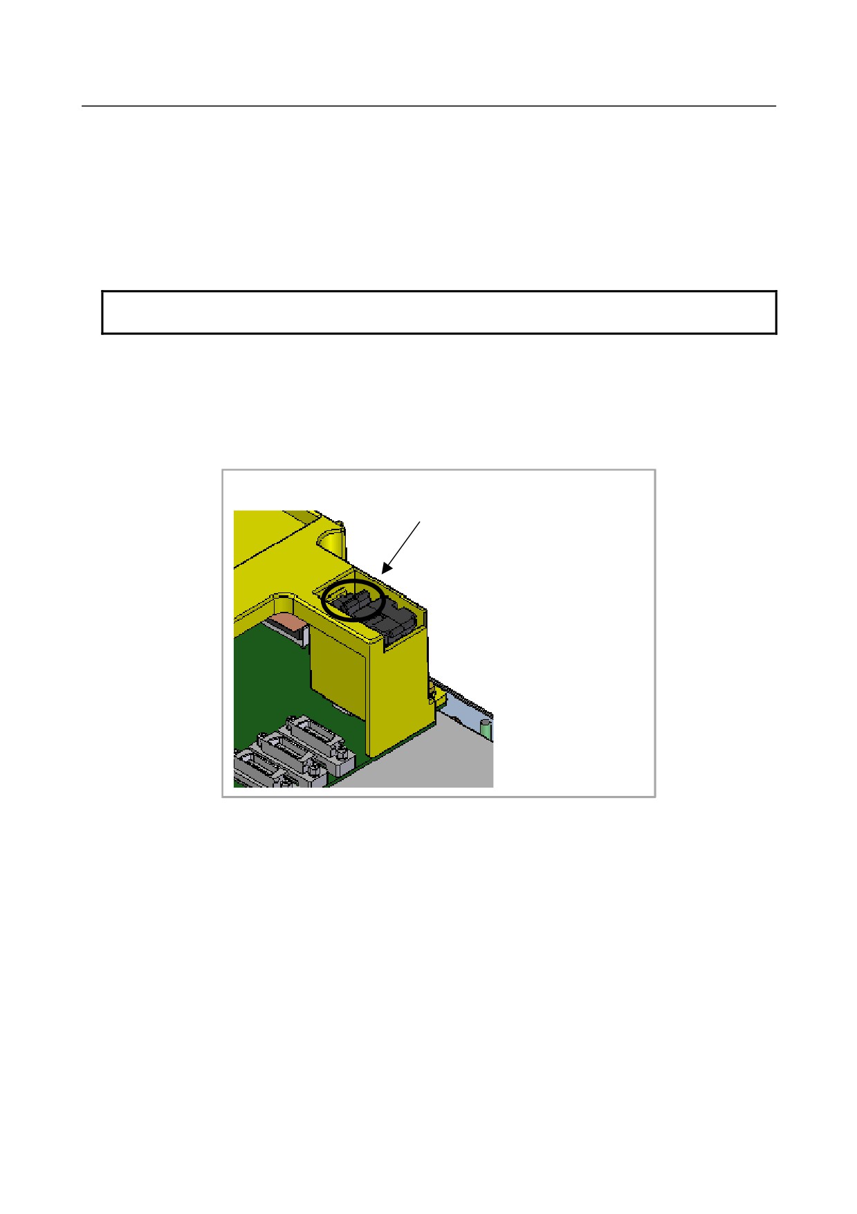
Prepare a new battery unit (ordering code: A02B-0309-K102).
(1) Turn on the power to the CNC. After about 30 seconds, turn off the power.
(2) Extract the old battery unit from the lower right of the rear of the CNC unit. (Hold the latch of the
battery unit, and extract the unit upward while releasing the claw from the case.)
Extract the unit while holding this portion.
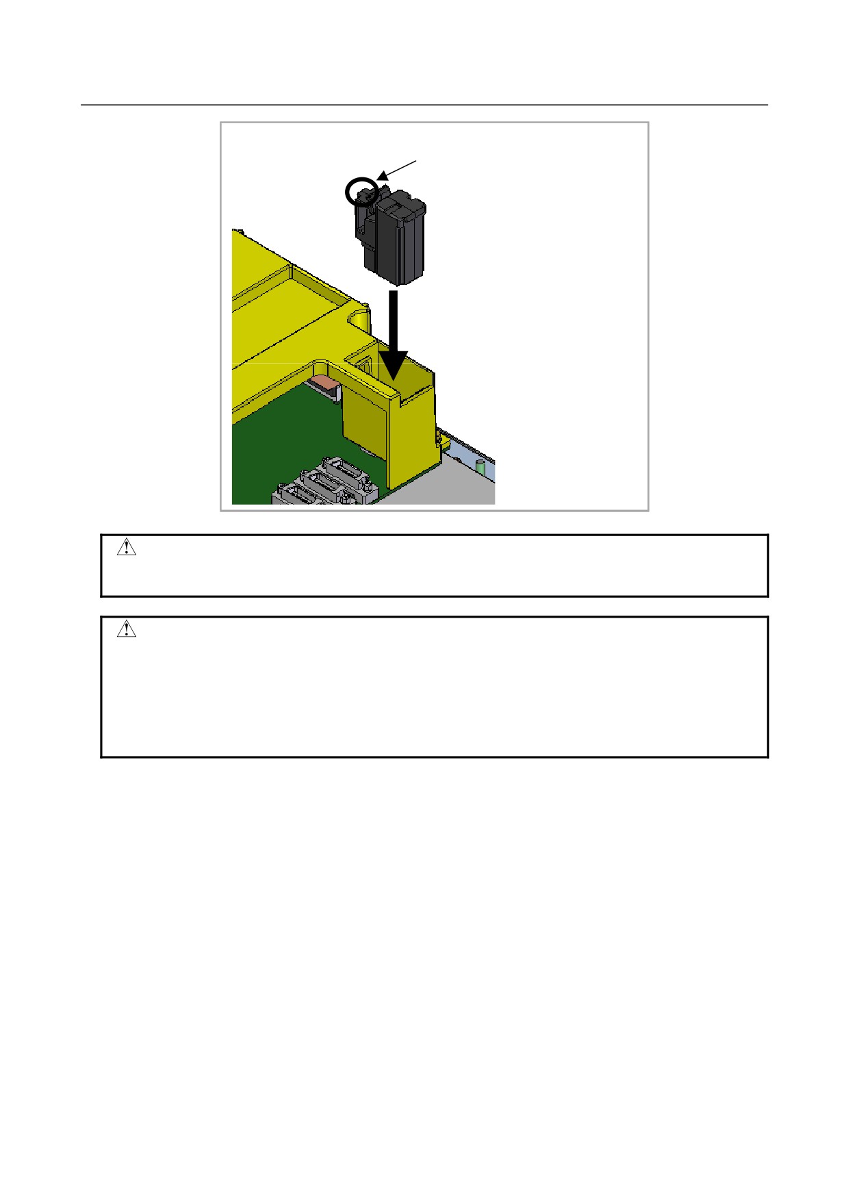
(3) Mount the new battery unit. (Push the battery unit in until the claw is latched into the case.) Ensure
that the latch is engaged securely.
- 38 -
B-64303EN/03
4.POWER SUPPLY CONNECTION
Push the unit in until the claw is
latched into the case.
WARNING
Using other than the recommended battery may result in the battery exploding.
Replace the battery only with the specified battery (A02B-0309-K102).
CAUTION
Steps 1 to 3 should be completed within 30 minutes. Do not leave the control
unit without a battery for any longer than the specified period. Otherwise, the
contents of memory may be lost.
If steps 1 to 3 may not be completed within 30 minutes, save all contents of the
SRAM memory to the memory card beforehand. Thus, if the contents of the
SRAM memory are lost, the contents can be restored easily.
When discarding a battery, observe the applicable ordinances or other rules of your local government.
In addition, cover the exposed pins with tape or other insulation materials to prevent a short circuit before
discarding the battery.
When using commercial alkaline dry cells (size D)
To use commercial alkaline dry cells (size D) instead of the lithium battery attached to the control unit,
install the battery unit in other than the control unit.
- Connection method
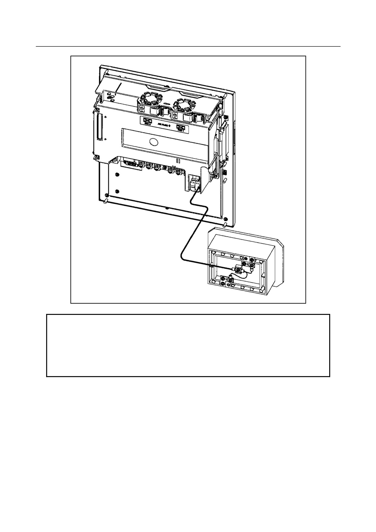
Remove the factory-mounted lithium battery from the control unit as described in the battery replacement
method above. Connect the battery cable (A02B-0309-K103) to the battery case (A02B-0236-C282). This
battery cable has the same connector as the lithium battery unit, so connect the connector to the place
where the lithium battery unit was installed as shown in the figure below. Since the connector has a
simple lock system, make sure that the lock is applied during installation.
- 39 -
4.POWER SUPPLY CONNECTION
B-64303EN/03
NOTE
1 The battery case (A02B-0236-C282) needs to be installed in a position
where dry cells can be replaced even when the control unit is powered on.
2 The connector part of this battery cable engages with a simple lock system.
Therefore, fix a cable portion up to 500mm long from the connector side
without the portion being yanked to prevent the connector being removed by
the cable weight or tensile stress.
- 40 -
B-64303EN/03
4.POWER SUPPLY CONNECTION
Replacing the alkaline dry cells (size D)
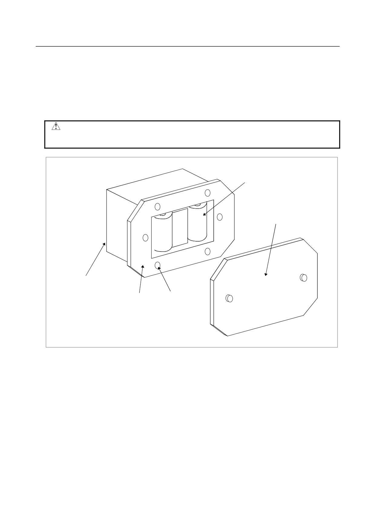
-
Replacing the battery
(1) Prepare two new alkaline dry cells (size D).
(2) Turn on the power of the control unit.
(3) Remove the battery case cover.
(5) Replace the batteries, paying careful attention to their orientation.
(6) Replace the battery case cover.
CAUTION
To replace the battery when the power is off, follow the same procedure as that
for the replacement of a lithium battery, described above.
Dry cell × 2
Cover
Connection terminal
on the rear
Battery case
Mounting hole × 4
- 41 -
4.POWER SUPPLY CONNECTION
B-64303EN/03
4.4.2
Battery for Separate Absolute Pulsecoders (6VDC)
The current position data of the absolute pulse coder connected to the separate detector interface unit is
saved by the battery connected to connector JA4A of the separate detector interface unit.
If the voltage of the battery drops, DS alarms 306 to 308 are issued. When DS alarm 307 (battery
voltage drop alarm) occurs, replace the battery as soon as possible. Estimated time to run out of the
battery is 1 to 2 weeks, but the actual life depends on the number of pulse coders.
If the voltage of the battery further drops, DS alarms 306 (battery zero alarm) occurs. In this case, the
current position of the pulse coder cannot be recorded and DS alarm 300 (reference position return alarm)
occurs. Replace the battery and perform a reference position return.
Although the battery life depends on the number of pulse coders connected, it is recommended that the
battery be replaced annually regardless of the issuance of the above alarms.
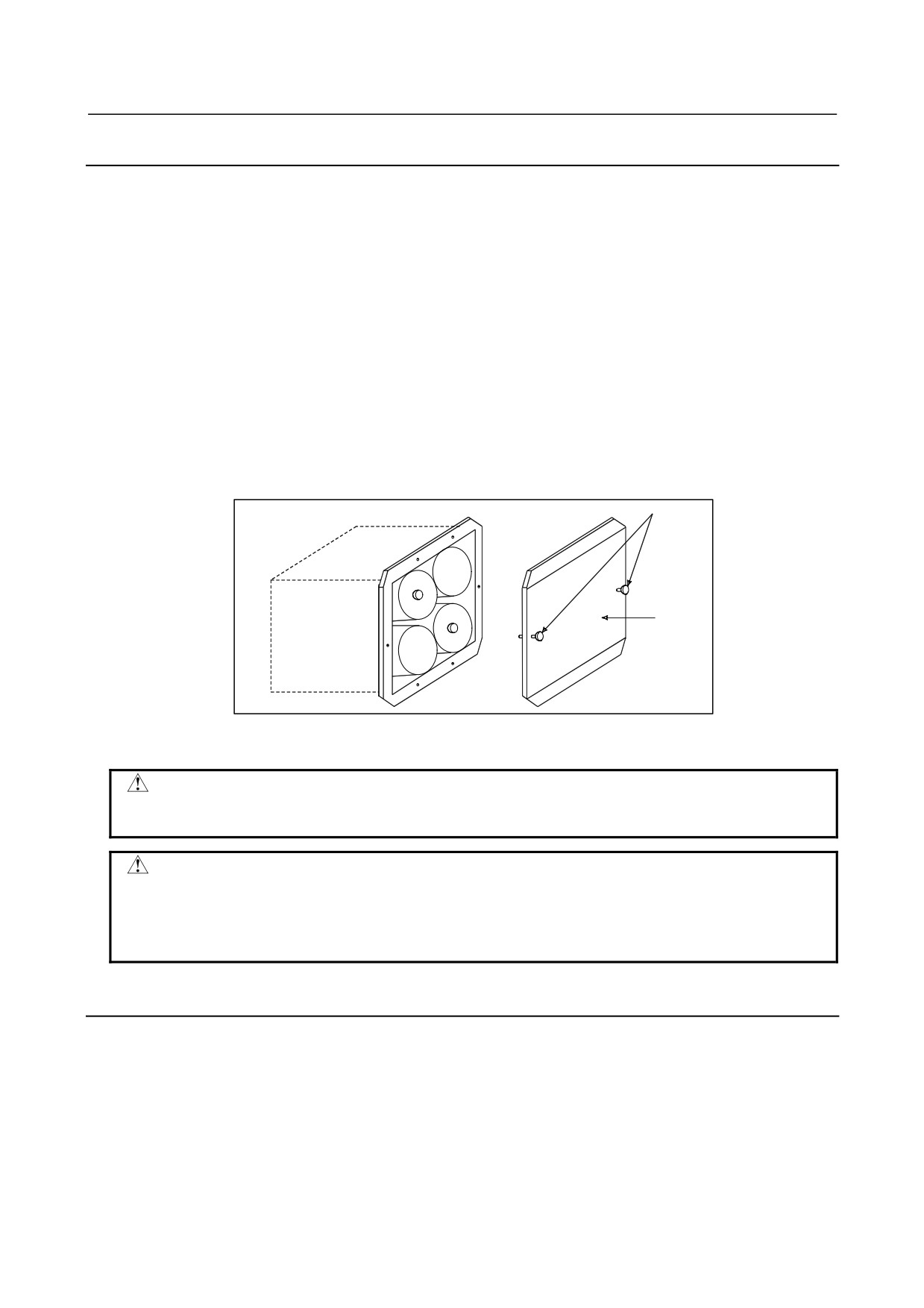
Replacing a battery
Obtain four commercially available alkaline batteries (size D).
(1) Turn on the power of the machine (CNC).
(2) Loosen the screws of the battery case, and remove the cover.
(3) Replace the dry batteries in the case.
Screws
Cover
(4) After installing the new batteries, replace the cover.
(5) Turn off the power to the machine (CNC).
WARNING
If the batteries are installed incorrectly, an explosion may occur. Never use
batteries other than the specified type (Size D alkaline batteries).
CAUTION
The battery must be replaced with the power of the CNC turned on (the servo
amplifier turned on).
Note that, if batteries are replaced while no power is supplied to the CNC, the
recorded absolute position is lost.
4.4.3
Battery for Absolute Pulsecoder Built into the Motor (6VDC)
The battery for the absolute pulse coder built into the motor is installed in the servo amplifier. For the
methods of connection and replacement, refer to the maintenance manual of your servo amplifier.
- 42 -

B-64303EN/03
5.CONNECTION TO CNC PERIPHERALS
5 CONNECTION TO CNC PERIPHERALS
5.1
CONNECTION WITH DISPLAY UNIT/MDI UNIT
5.1.1
Overview
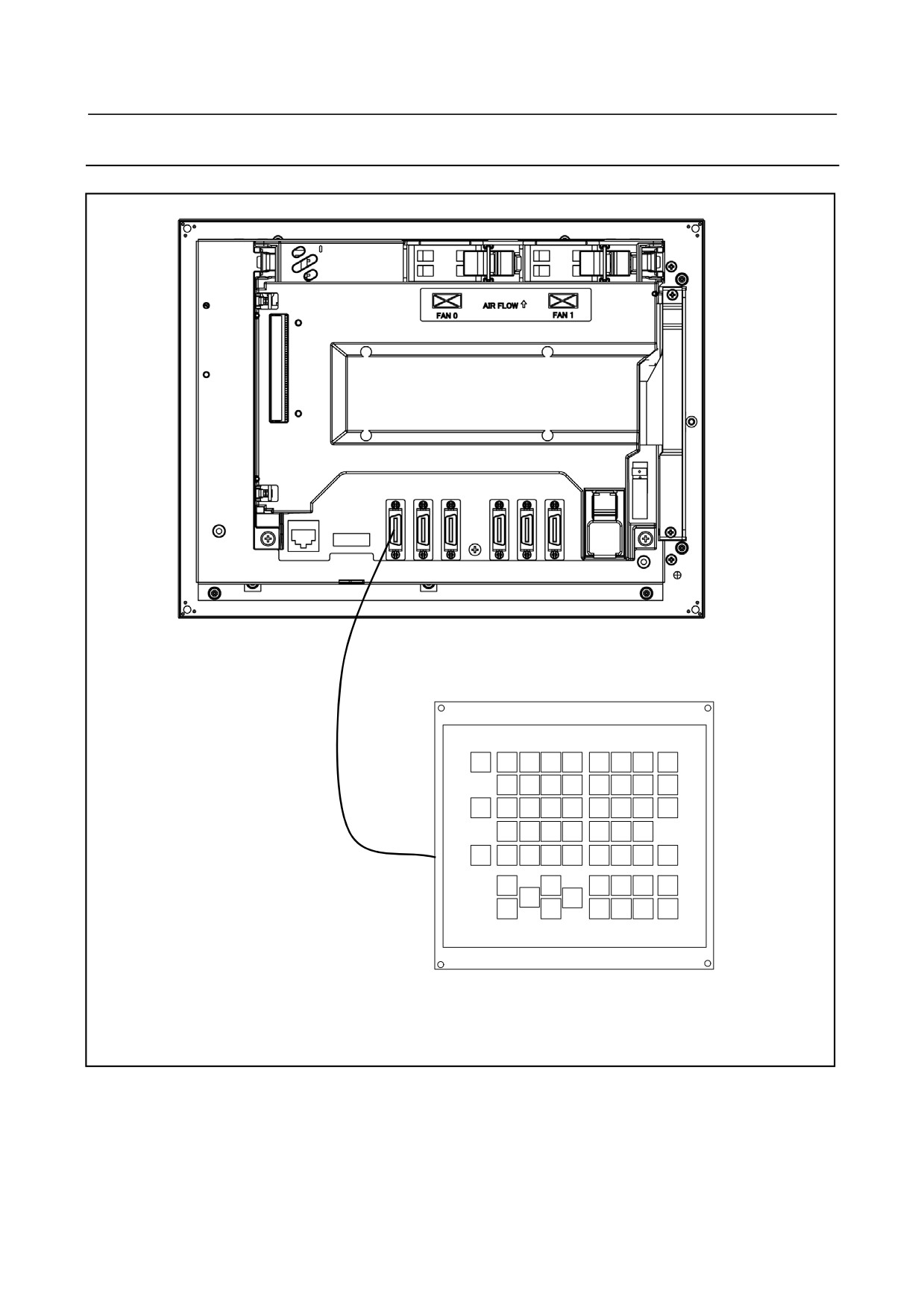
The CNC controller and the display unit are connected within the unit, so a machine tool builder does not
need to connect them. The MDI cable is also included except for the 10.4" color LCD, so a machine
tool builder does not need to connect it. Therefore, this subsection describes how to connect the CNC
control unit and the MDI unit for the 10.4" color LCD.
- 43 -
5.CONNECTION TO CNC PERIPHERALS
B-64303EN/03
5.1.2
Connection to the MDI Unit
Rear of unit
JA2
MDI Cable
MDI unit
- 44 -
B-64303EN/03
5.CONNECTION TO CNC PERIPHERALS
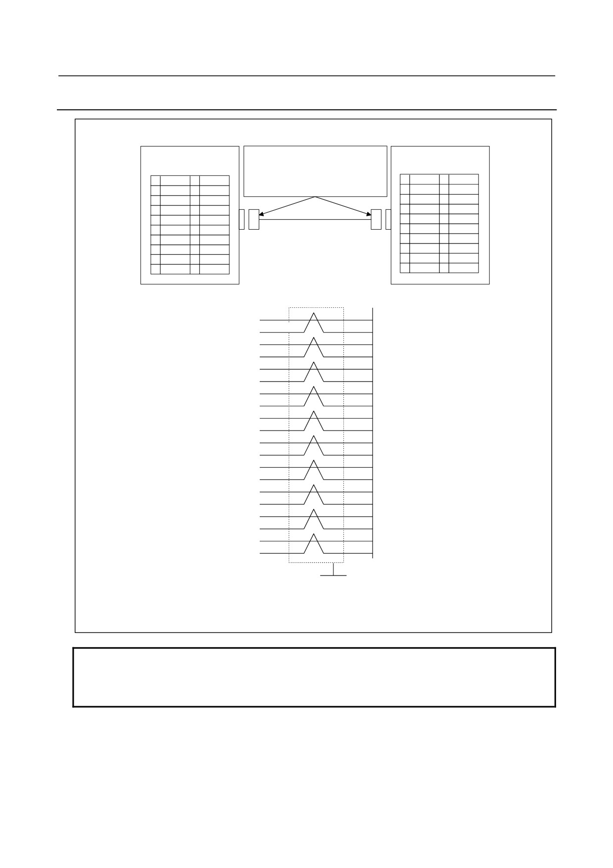
5.1.3
Connection with the Standard MDI Unit
Honda tsushin Kogyo Co., Ltd. (including
Control unit
MDI unit
housings)
JA2
PCR-E20FA-E20SPF1A+
(press-mount
CK1
type) or
01
*KEY00
11
*KEY01
01
*KEY00
11
*KEY01
PCR-E20FS-E20SPF1A+ (soldering type)
02
*KEY02
12
*KEY03
02
*KEY02
12
*KEY03
03
*KEY04
13
*KEY05
03
*KEY04
13
*KEY05
04
*KEY06
14
*KEY07
04
*KEY06
14
*KEY07
05
*COM00
15
*COM01
05
*COM00
15
*COM01
06
*COM02
16
*COM03
06
*COM02
16
*COM03
07
*COM04
17
*COM05
07
*COM04
17
*COM05
08
*COM06
18
*COM07
08
*COM06
18
*COM07
09
*COM08
19
*COM09
09
*COM08
19
*COM09
10
*COM10
20
*COM11
10
*COM10
20
*COM11
01
01
*KEY00
*KEY00
02
02
*KEY02
*KEY02
11
11
*KEY01
*KEY01
12
12
*KEY03
*KEY03
03
03
*KEY04
*KEY04
04
04
*KEY06
*KEY06
13
13
*KEY05
*KEY05
14
14
*KEY07
*KEY07
05
05
*COM00
*COM00
06
06
*COM02
*COM02
15
15
*COM01
*COM01
16
16
*COM03
*COM03
07
07
*COM04
*COM04
08
08
*COM06
*COM06
17
17
*COM05
*COM05
18
18
*COM07
*COM07
09
09
*COM08
*COM08
10
10
*COM10
*COM10
19
19
*COM09
*COM09
20
20
*COM11
*COM11
Shield
Grounding plate
Recommended cable specification: A02B-0309-K813(45cm)
Recommended wire specification:A66L-0001-0284#10P(#28AWG × 10 pairs)
NOTE
The MDI cable needs to be clamped to prevent a heavy load caused by vibration
from being applied to the cable. When the cable length is 50 cm or less,
however, shielding or clamping is not necessary.
- 45 -
5.CONNECTION TO CNC PERIPHERALS
B-64303EN/03
5.1.4
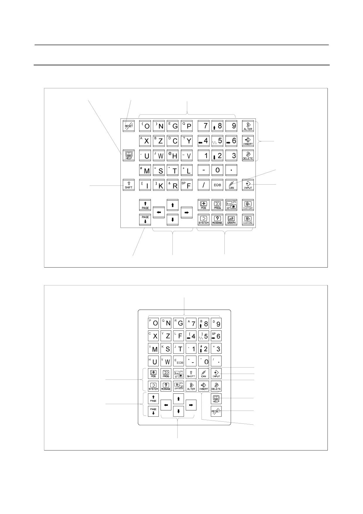
Key Layout of MDI
For Lathe (T series)
-
Standard MDI unit (ONG keys)
HELP key
RESET key
Address keys/Numeric keys
Edit keys
Cancel (CAN) key
SHIFT key
INPUT key
Page change keys
Cursor move keys
Function keys
-
Small MDI unit (OGN keys, horizontal type)
Address keys/Numeric keys
Cancel (CAN) key
INPUT key
Function keys
SHIFT key
HELP key
Page change keys
RESET key
Edit keys
Cursor move keys
- 46 -