FANUC Series 0i-MODEL D, Series 0i Mate-MODEL D. CONNECTION MANUAL (HARDWARE) - page 1
B-64303EN/03
DEFINITION OF WARNING, CAUTION, AND NOTE
DEFINITION OF WARNING, CAUTION, AND NOTE
This manual includes safety precautions for protecting the user and preventing damage to the machine.
Precautions are classified into Warning and Caution according to their bearing on safety. Also,
supplementary information is described as a Note. Read the Warning, Caution, and Note thoroughly
before attempting to use the machine.
WARNING
Applied when there is a danger of the user being injured or when there is a
danger of both the user being injured and the equipment being damaged if the
approved procedure is not observed.
CAUTION
Applied when there is a danger of the equipment being damaged, if the
approved procedure is not observed.
NOTE
The Note is used to indicate supplementary information other than Warning and
Caution.
• Read this manual carefully, and store it in a safe place.
s-1
B-64303EN/03
PREFACE
PREFACE
This manual describes the electrical and structural specifications required for connecting the CNC control
unit to a machine tool. The manual outlines the components commonly used for FANUC CNC control
units, as shown in the configuration diagram in Chapter 2, and supplies additional information on using
these components.
The manual outlines the I/O unit, servo, spindle, and other components common to FANUC CNC
control units, and supplies additional information on using these components in this CNC control unit.
For detailed specifications, refer to the manuals of these components.
For options not covered in this manual, also refer to the manuals of these components.
Applicable models
The models covered by this manual, and their abbreviations are :
Model name
Abbreviation
FANUC Series 0i-TD
0i -TD
Series 0i
FANUC Series 0i-MD
0i -MD
FANUC Series 0i Mate-TD
0i Mate-TD
Series 0i Mate
FANUC Series 0i Mate-MD
0i Mate-MD
Organization of this manuals
This manual consists of chapters 1 to 12 and appendixes at the end of the book.
Chapter and title
Contents
Chapter 1
Provides general information related to the connection of the CNC, as well
CONFIGURATION
as an introduction to detailed information.
Chapter 2
Describes how to connect peripheral units to the CNC.
TOTAL CONNECTION DAIGRAMS
Chapter 3
Describes the installation requirements for using the CNC.
INSTALLATION
1) Required power supply capacity
2) Heat output
3) Locations of connectors on the control unit
4) Action against noise
Chapter 4
Describes how to make connections related to the power supply of the
POWER SUPPLAY CONNECTION
CNC.
Chapter 5
Describes how to connect the following peripheral devices to the CNC:
CONNECTION TO CNC
1) Display unit / MDI unit
PERIOHERALS
2) I/O device (RS-232-C)
3) High-speed skip (HDI)
4) Embedded Ethernet
5) Connection to the touch panel
Chapter 6
Describes how to connect spindle-related units to the CNC.
SPINDLE CONNECTION
Chapter 7
Describes how to connect servo-related units to the CNC.
SERVO INTERFACE
Chapter 8
Describes how to connect machine interface I/O with the FANUC I/O Link.
CONNECTION TO FANUC I/O Link
Chapter 9
Describes how to connect various I/O Link slave devices.
CONNECTION OF I/O Link SLAVE
It also describes I/O units for the 0i.
DEVICES
Chapter 10
Describes how to handle the emergency stop signal.
STOP AND EMERGENCY STOP
Be sure to read this chapter.
p-1
PREFACE
B-64303EN/03
Chapter and title
Contents
Chapter 11
Describes connection to the following networks.
CONNECTION TO OTHER
For details on the connection, refer to the following manuals provided
NETWORKS
separately.
Manual name (Specification number)
• FANUC Fast Ethernet / Fast Data Server For FANUC Series
0i-MODEL D OPERATOR’S MANUAL (B-64414EN)
• FANUC Series 0i-MODEL D PROFIBUS-DP Board CONNECTION
MANUAL (B-64403EN)
• FANUC Series 0i-MODEL D DeviceNet Board CONNECTION
MANUAL (B-64443EN)
• FANUC Series 0i-MODEL D FL-net Board CONNECTION MANUAL
(B-64453EN)
Chapter 12
Provides descriptions specific to connection of the stand-alone type Series
CONNECTION OF THE
0i-D.
STAND-ALONE TYPE
APPENDIX
A) OUTLINE DRAWINGS OF UNITS
B)
20-PIN INTERFACE CONNECTORS AND CABLES
C) CONNECTION CABLE (SUPPLIED FROM US)
D) OPTICAL FIBER CABLE
E) LIQUID CRYSTAL DISPLAY (LCD)
F) MEMORY CARD INTERFACE
Related manuals of Series 0i -D, Series 0i Mate -D
The following table lists the manuals related to Series 0i -D, Series 0i Mate -D. This manual is indicated
by an asterisk(*).
Table 1 Related manuals of Series 0i-D, Series 0i Mate-D
Manual name
Specification number
DESCRIPTIONS
B-64302EN
CONNECTION MANUAL (HARDWARE)
B-64303EN
*
CONNECTION MANUAL (FUNCTION)
B-64303EN-1
USER’S MANUAL (Common to Lathe System/Machining Center System)
B-64304EN
USER’S MANUAL (For Lathe System)
B-64304EN-1
USER’S MANUAL (For Machining Center System)
B-64304EN-2
MAINTENANCE MANUAL
B-64305EN
PARAMETER MANUAL
B-64310EN
START-UP MANUAL
B-64304EN-3
Programming
Macro Executor PROGRAMMING MANUAL
B-64303EN-2
Macro Compiler PROGRAMMING MANUAL
B-64303EN-5
C Language Executor PROGRAMMING MANUAL
B-64303EN-3
PMC
PMC PROGRAMMING MANUAL
B-64393EN
Network
PROFIBUS-DP Board CONNECTION MANUAL
B-64403EN
Fast Ethernet / Fast Data Server OPERATOR’S MANUAL
B-64414EN
DeviceNet Board CONNECTION MANUAL
B-64443EN
FL-net Board CONNECTION MANUAL
B-64453EN
Dual Check Safety
Dual Check Safety CONNECTION MANUAL
B-64303EN-4
Operation guidance function
MANUAL GUIDE i (Common to Lathe System/Machining Center System)
B-63874EN
OPERATOR’S MANUAL
MANUAL GUIDE i (For Machining Center System) OPERATOR’S MANUAL
B-63874EN-2
p-2
B-64303EN/03
PREFACE
Manual name
Specification number
MANUAL GUIDE i Set-up Guidance OPERATOR’S MANUAL
B-63874EN-1
MANUAL GUIDE 0i OPERATOR’S MANUAL
B-64434EN
TURN MATE i OPERATOR’S MANUAL
B-64254EN
CNC Screen Display function
CNC Screen Display Function OPERATOR’S MANUAL
B-63164EN
Related manuals of SERVO MOTOR αis/βis/αi/βi series
The following table lists the manuals related to SERVO MOTOR αis/βis/αi/βi series
Table 2 Related manuals of SERVO MOTOR αis/βis/αi/βi series
Manual name
Specification number
FANUC AC SERVO MOTOR αi series DESCRIPTIONS
B-65262EN
FANUC AC SPINDLE MOTOR αi series DESCRIPTIONS
B-65272EN
FANUC AC SERVO MOTOR βi series DESCRIPTIONS
B-65302EN
FANUC AC SPINDLE MOTOR βi series DESCRIPTIONS
B-65312EN
FANUC SERVO AMPLIFIER αi series DESCRIPTIONS
B-65282EN
FANUC SERVO AMPLIFIER βi series DESCRIPTIONS
B-65322EN
FANUC AC SERVO MOTOR αis series
FANUC AC SERVO MOTOR αi series
B-65285EN
FANUC AC SPINDLE MOTOR αi series
FANUC SERVO AMPLIFIER αi series MAINTENANCE MANUAL
FANUC SERVO MOTOR βis series
FANUC AC SPINDLE MOTOR βi series
B-65325EN
FANUC SERVO AMPLIFIER βi series MAINTENANCE MANUAL
FANUC AC SERVO MOTOR αi series
FANUC AC SERVO MOTOR βi series
FANUC LINEAR MOTOR LiS series
B-65270EN
FANUC SYNCHRONOUS BUILT-IN SERVO MOTOR DiS series
PARAMETER MANUAL
FANUC AC SPINDLE MOTOR αi series
FANUC AC SPINDLE MOTOR βi series
B-65280EN
BUILT-IN SPINDLE MOTOR Bi series
PARAMETER MANUAL
This manual mainly assumes that the FANUC SERVO MOTOR αi series of servo motor is used. For
servo motor and spindle information, refer to the manuals for the servo motor and spindle that are actually
connected.
Related manuals of FANUC PANEL i
The following table lists the manuals related to FANUC PANEL i.
Table 3 Related manuals of FANUC PANEL i
Manual name
Specification number
FANUC PANEL i CONNECTION AND MAINTENANCE MANUAL
B-64223EN
p-3
B-64303EN/03
TABLE OF CONTENTS
TABLE OF CONTENTS
DEFINITION OF WARNING, CAUTION, AND NOTE
s-1
PREFACE
p-1
1
CONFIGURATION
1
1.1
CONTROL UNIT CONFIGURATION AND COMPONENT NAMES
1
1.1.1
Configurations of Control Units
1
1.2
HARDWARE OVERVIEW
5
1.2.1
Control Unit Overview
5
2
TOTAL CONNECTION DIAGRAMS
6
3
INSTALLATION
9
3.1
ENVIRONMENTAL REQUIREMENTS
9
3.1.1
Environmental Conditions External to Cabinets
9
3.1.2
Environmental Conditions of the Control Unit
9
3.2
POWER SUPPLY CAPACITY
10
3.2.1
Power Supply Capacities of CNC-related Units
10
3.3
DESIGN AND INSTALLATION CONDITIONS OF THE MACHINE TOOL
MAGNETIC CABINET
11
3.4
THERMAL DESIGN OF THE MACHINE TOOL MAGNETIC CABINET
12
3.4.1
Temperature Rise within the Machine Tool Magnetic Cabinet
12
3.4.2
Heat Output of Each Unit
12
3.4.3
Thermal Design of Operator's Panel
13
3.5
COUNTERMEASURES AGAINST NOISE
15
3.5.1
Grounding
15
3.5.1.1
About grounding types
15
3.5.1.2
Grounding methods
15
3.5.1.3
Cable clamp and shield processing
19
3.5.1.4
Cabinet
21
3.5.2
Connecting the Ground Terminal of the Control Unit
23
3.5.3
Separating Signal Lines
26
3.5.4
Noise Suppressor
27
3.5.5
Measures Against Surges due to Lightning
28
3.6
CONTROL UNIT
29
3.6.1
Installation of the Control Unit
29
3.7
SEVERE DUST/LIQUID PROTECTION OF CABINETS AND PENDANT
BOXES
30
4
POWER SUPPLY CONNECTION
32
4.1
GENERAL
32
4.2
TURNING ON AND OFF THE POWER TO THE CONTROL UNIT
32
4.2.1
Power Supply for the Control Unit
32
4.2.2
External 24 VDC Power Specification and Circuit Configuration
32
4.2.3
Power-on Sequence
36
4.2.4
Power-off Sequence
36
4.3
CABLE FOR POWER SUPPLY TO CONTROL UNIT
37
4.4
BATTERIES
37
4.4.1
Battery for Memory Backup in the CNC Control Unit (3 VDC)
37
c-1
TABLE OF CONTENTS
B-64303EN/03
4.4.2
Battery for Separate Absolute Pulsecoders (6VDC)
42
4.4.3
Battery for Absolute Pulsecoder Built into the Motor (6VDC)
42
5
CONNECTION TO CNC PERIPHERALS
43
5.1
CONNECTION WITH DISPLAY UNIT/MDI UNIT
43
5.1.1
Overview
43
5.1.2
Connection to the MDI Unit
44
5.1.3
Connection with the Standard MDI Unit
45
5.1.4
Key Layout of MDI
46
5.2
CONNECTION WITH INPUT/OUTPUT DEVICES
49
5.2.1
Overview
49
5.2.2
Connecting I/O Devices
50
5.2.3
RS-232-C Serial Port
51
5.2.4
RS-232-C Interface Specification
53
5.3
CONNECTING THE HIGH-SPEED SKIP (HDI)
60
5.3.1
Connecting the High-speed Skip (HDI)
60
5.3.2
Input Signal Rules for the High-speed Skip (HDI)
61
5.4
LINKING THE EMBEDDED ETHERNET INTERFACE
62
5.4.1
Connection to the Ethernet Interface
62
5.4.2
Specification of Twisted-Pair Cable
64
5.4.3
Anti-Noise Measure
66
5.4.4
Network Installation
66
5.5
CONNECTION TO THE TOUCH PANEL
68
5.5.1
Connection of the LCD Unit with a Touch Panel
68
5.5.2
External Touch Panel Interface
69
6
SPINDLE CONNECTION
71
6.1
SERIAL SPINDLE
73
6.1.1
Connection of One to Two Serial Spindles
73
6.1.2
Connecting Three Serial Spindles
75
6.2
ANALOG SPINDLE
80
6.3
POSITION CODER
81
7
SERVO INTERFACE
82
7.1
CONNECTION TO THE SERVO AMPLIFIERS
82
7.1.1
Overview
83
7.1.2
Interface to the Servo Amplifiers
83
7.2
SEPARATE DETECTOR INTERFACE
84
7.2.1
Separate Detector Interface Unit Specification
85
7.2.2
Connection of Power Supply
86
7.2.3
Separate Detector Interface (Serial Interface)
88
7.2.4
Separate Detector Interface (Parallel interface)
90
7.2.5
Input Signal Requirements (Parallel interface)
91
7.2.6
Connection of Battery for Absolute Position Detector
93
7.2.7
Connection Between the Basic Unit and Additional Unit
95
7.2.8
Connector Locations
95
7.2.9
Installation
96
7.2.10
Notes on Installing a Separate Detector Interface Unit
97
7.3
ANALOG INPUT SEPARATE DETECTOR INTERFACE
100
7.3.1
Overview
101
7.3.2
Analog Input Separate Detector Interface Unit Specification
103
7.3.3
Connection of Power Supply
104
7.3.4
Analog Input Separate Detector Interface (Analog 1Vp-p Interface)
106
c-2
B-64303EN/03
TABLE OF CONTENTS
7.3.5
Input Signal Specifications
107
7.3.6
Connection of Battery for Absolute Position Detector
108
7.3.7
Connection Between the Analog Input Separate Detector Interface Unit and
Additional Unit
109
7.3.8
Connector Locations
109
7.3.9
Installation
110
7.3.10
Notes on Installing an Analog Input Separate Detector Interface Unit
111
8
CONNECTION TO FANUC I/O Link
113
8.1
OVERVIEW
113
8.2
CONNECTION
113
8.2.1
Connection of FANUC I/O Link by Electric Cable
116
8.2.2
Connection of FANUC I/O Link by Optical Fiber Cable
117
8.2.3
Connection when Multiple Channels of FANUC I/O Links are Used
120
8.2.4
Power Supply Precautions
123
9
CONNECTION OF I/O Link SLAVE DEVICES
124
9.1
UNITS CONNECTABLE WITH THE FANUC I/O LINK
124
9.2
CONNECTION OF CONNECTOR PANEL I/O MODULE
125
9.2.1
Configuration
125
9.2.2
Connection Diagram
126
9.2.3
Module Specifications
127
9.2.4
DI/DO Connector Pin Assignment
129
9.2.5
DI (Input Signal) Connection
130
9.2.6
DO (Output Signal) Connection
132
9.2.7
DI/DO Signal Specifications
133
9.2.8
2A Output Connector Pin Allocation
134
9.2.9
2A DO (Output Signal) Connection
135
9.2.10
2A Output DO Signal Specifications
136
9.2.11
Analog Input Connector Pin Allocation
137
9.2.12
Analog Input Signal Connections
138
9.2.13
Analog Input Signal Specifications
139
9.2.14
Analog Input Specifications
139
9.2.15
Manual Pulse Generator Connection
141
9.2.16
Cable Length for Manual Pulse Generator
142
9.2.17
Connection of Basic and Expansion Modules
142
9.2.18
Module Installation
144
9.2.19
Other Notes
148
9.2.20
Distribution I/O Setting
151
9.3
CONNECTION OF OPERATOR'S PANEL I/O MODULE (FOR MATRIX
INPUT)
153
9.3.1
Overall Connection Diagram
153
9.3.2
Power Connection
154
9.3.3
DI/DO Connector Pin Arrangement
155
9.3.4
DI (General-purpose Input Signal) Connection
156
9.3.5
DI (Matrix Input Signal) Connection
157
9.3.6
DO (Output Signal) Connection
159
9.3.7
Manual Pulse Generator Connection
163
9.3.8
External View
163
9.3.9
Specifications
164
9.3.10
Other Notes
165
9.4
CONNECTION OF OPERATOR'S PANEL I/O MODULE AND POWER
MAGNETICS CABINET I/O MODULE
169
9.4.1
Overall Connection Diagram
169
c-3
TABLE OF CONTENTS
B-64303EN/03
9.4.2
Power Connection
170
9.4.3
DI/DO Connector Pin Arrangement
171
9.4.4
DI (General-purpose Input Signal) Connection
172
9.4.5
DO (Output Signal) Connection
176
9.4.6
Manual Pulse Generator Connection
177
9.4.7
External View
178
9.4.8
Specifications
179
9.4.9
Other Notes
180
9.5
I/O MODULE TYPE-2 FOR CONNECTOR PANEL
183
9.5.1
Configuration
183
9.5.2
Connector Layout Diagram
184
9.5.3
Connection Diagram
185
9.5.4
Module Specifications
186
9.5.5
DI/DO Connector Pin Assignment
187
9.5.6
DI (Input Signal) Connection
188
9.5.7
DO (Output Signal) Connection
194
9.5.8
DI/DO Signal Specifications
198
9.5.9
Power Supply Connection
199
9.5.10
Manual Pulse Generator Connection
199
9.5.11
Cable Length for Manual Pulse Generator
199
9.5.12
Connection between Modules
200
9.5.13
Unit Dimensions
201
9.5.14
Mounting the Module
201
9.5.15
Connector Panel Printed Circuit Board
203
9.5.16
Other Notes
205
9.6
CONNECTION OF I/O UNITS FOR 0i
207
9.6.1
Overview
207
9.6.2
Cautions
209
9.6.3
Cable for Power Supply to Control Unit
210
9.6.4
Connector Pin Arrangement
211
9.6.5
Connecting DI/DO
212
9.6.6
I/O Signal Requirements and External Power Supply for DO
221
9.6.7
Connecting the Manual Pulse Generator
226
9.7
FANUC I/O LINK CONNECTION UNIT
230
9.7.1
Overview
230
9.7.2
Specification
231
9.7.3
Connection
234
9.7.3.1
I/O Link interface
234
9.8
CONNECTING THE FANUC SERVO UNIT β SERIES WITH I/O LINK
236
9.8.1
Overview
236
9.8.2
Connection
237
9.8.3
Maximum Number of Units that can be Connected
237
9.8.4
Address Assignment by Ladder
237
9.9
CONNECTION TO STANDARD MACHINE OPERATOR'S PANEL
238
9.9.1
Overview
238
9.9.2
Total Connection Diagram
239
9.9.3
Each Connections
240
9.9.3.1
Pin assignment
240
9.9.3.2
Power supply connection
241
9.9.3.3
I/O Link connection
242
9.9.3.4
Emergency stop signal connection
243
9.9.3.5
Power ON/OFF control signal connection
243
9.9.3.6
General-purpose DI signal connection
244
9.9.3.7
General-purpose DO signal connection
246
c-4
B-64303EN/03
TABLE OF CONTENTS
9.9.3.8
Manual pulse generator connection
246
9.9.3.9
Connector (on the cable side) specifications
249
9.9.4
I/O Address
250
9.9.4.1
Keyboard of main panel
250
9.9.4.2
Override signals
250
9.9.5
I/O Mapping
251
9.9.5.1
Connector locations of main panel
252
9.9.6
Specifications
254
9.9.6.1
Environmental requirement
254
9.9.6.2
Order specification
254
9.9.6.3
Main panel specification
254
9.9.6.4
Sub panel A/B1 specification
254
9.9.6.5
Power supply specification
255
9.9.6.6
General-purpose DI signal definition
255
9.9.6.7
General-purpose DO signal definition
255
9.9.7
Key Symbol Indication on Machine Operator’s Panel
255
9.9.7.1
Meaning of key symbols
255
9.9.7.2
Detachable key top
257
9.10
CONNECTION TO THE SMALL MACHINE OPERATOR'S PANEL OR
SMALL MACHINE OPERATOR'S PANEL B
258
9.10.1
Overview
258
9.10.2
Overall Connection Diagram
258
9.10.3
Connection of Each Section
260
9.10.3.1 Power connection
260
9.10.3.2 Emergency stop switch
260
9.10.3.3 I/O Link connection
261
9.10.3.4 Manual pulse generator connection
261
9.10.4
DI Signal Connection (Rotary Switch Connection)
263
9.10.5
General-purpose DI/DO Connection (Only for the Small Machine Operator's
Panel B)
264
9.10.5.1 Connector pin allocation
264
9.10.5.2 General-purpose DI (input signal) connection
265
9.10.5.3 General-purpose DO (output signal) connection
267
9.10.6
I/O Address
268
9.10.6.1 Keyboard of the operator's panel
268
9.10.6.2 Override signals
269
9.10.7
I/O Address Allocation
270
9.10.7.1 For small machine operator's panel
270
9.10.7.2 For small machine operator's panel B
271
9.10.8
External Dimensions
274
9.10.8.1 Outline drawing and panel-cut drawing of the small machine operator's
panel
274
9.10.8.2 Layout of the key sheet (Same for both the small machine operator's panel
and small machine operator's panel B)
276
9.10.9
Connector Layout of the Small Machine Operator's Panel
278
9.10.10
Specifications
279
9.10.10.1 Environmental requirement
279
9.10.10.2 Order specification
279
9.10.10.3 Operator's panel specification
280
9.10.10.4 Power supply specification
280
9.10.11
Key Symbol Indication on Machine Operator's Panel
280
9.10.11.1 Meaning of key symbols
280
9.10.11.2 Customization of the key sheet
281
9.10.12
Maintenance Parts
282
9.11
CONNECTION OF TERMINAL TYPE I/O MODULE
282
9.11.1 Overview
282
c-5
TABLE OF CONTENTS
B-64303EN/03
9.11.2
Module Specifications
283
9.11.2.1 Types of modules
283
9.11.2.2 Installation conditions
284
9.11.2.3 I/O signal specifications
284
9.11.2.4 Power supply capacity
286
9.11.2.5 Heat dissipation
286
9.11.2.6 Weight
286
9.11.2.7 Applicable wire
287
9.11.3
External View and Dimensions
288
9.11.3.1 Dimensions (common to the modules)
288
9.11.3.2 Dimensions in a maximum configuration (one basic module + three
expansion modules)
288
9.11.3.3 Component names
289
9.11.4
Installation
294
9.11.5
Connection
296
9.11.5.1 Overall connection diagram
296
9.11.5.2 Power connection
297
9.11.5.3 Signal assignment on terminal blocks
298
9.11.5.4 DI/DO connection
301
9.11.5.5 Manual pulse generator connection
305
9.11.5.6 Inter-module connection
305
9.11.5.7 Cable connection to a terminal block
306
9.11.5.8 Detaching a terminal block
307
9.11.6
Settings
308
9.11.6.1 Address map
308
9.11.6.2 DO alarm detection
310
9.11.6.3 Setting the rotary switch
312
9.11.7
Others
314
9.11.7.1 Method of common pin expansion
314
9.11.7.2 DO signal reaction to a system alarm
315
9.11.7.3 Parallel DO (output signal) connection
316
9.12
CONNECTION OF THE I/O LINK-AS-i CONVERTER
317
9.12.1 Overview
317
9.12.1.1 Features
317
9.12.1.2 AS-i versions and ordering information
317
9.12.1.3 Applicable CNC
318
9.12.1.4 Specification of the I/O Link side
318
9.12.1.5 Support for AS-i profiles
318
9.12.2 Specifications
318
9.12.2.1 Specifications of the AS-i converter
318
9.12.2.2 Installation conditions
319
9.12.2.3 Dimensions and connector layout
319
9.12.2.4 Installation
320
9.12.3 Connection
323
9.12.3.1 Overall connection diagram
323
9.12.3.2 Power connection
323
9.12.3.3 I/O Link connection
325
9.12.3.4 AS-i connection
325
9.12.4 DI/DO Mapping on the I/O Link
326
9.12.4.1 For AS-i Ver. 2.0 (A03B-0817-C001)
326
9.12.4.2 For AS-i Ver. 2.1 (A03B-0817-C002)
327
9.12.5 Details of I/O Link DI/DO
329
9.12.5.1 Input/output data area
329
9.12.5.2 AS-i master status indication
330
9.12.5.3 Board status
331
9.12.5.4 Slave list
331
9.12.6 Command Execution by a Ladder Program
333
c-6
B-64303EN/03
TABLE OF CONTENTS
9.12.6.1 Types of commands executable by a ladder program
333
9.12.6.2 Command interface with a ladder program
333
9.12.6.3 Details of command flags and status
334
9.12.6.4 Error codes
334
9.12.6.5 Command handshake sequence
334
9.12.6.6 Details of commands
335
9.12.7 LED Status Indication and Setting Switch Operation
338
9.12.7.1 LED indication
338
9.12.7.2
7-segment LED indication
339
9.12.7.3
Setting/display switch
340
9.12.7.4
Error processing
341
9.12.8 How to Use the I/O Link-AS-i Converter
343
9.12.8.1 Installation
343
9.12.8.2 Normal operation
344
9.12.9 Others
345
9.12.9.1 CE marking
345
9.12.9.2 Fuse
345
10
STOP AND EMERGENCY STOP
346
10.1
STOP MODES
346
10.2
SHUTTING OFF THE MOTOR POWER
346
10.3
STOPPING THE SPINDLE MOTOR
347
10.4
STOPPING THE SERVO MOTOR
347
10.5
EMERGENCY STOP SIGNAL
348
11
CONNECTION TO OTHER NETWORKS
351
12
CONNECTION OF THE STAND-ALONE TYPE
352
12.1
OVERVIEW
352
12.2
CONTROL UNIT CONFIGURATION AND COMPONENT NAMES
353
12.3
CONTROL UNIT OVERVIEW
354
12.4
TOTAL CONNECTION DIAGRAMS
355
12.5
INSTALLATION
356
12.5.1 Environmental Conditions of the Control Unit
356
12.5.2 Power Supply Capacity
356
12.5.3 Heat Output of Each Unit
356
12.5.4 Connecting the Ground Terminal of the Control Unit
357
12.5.5 Installing the Control Unit
357
12.6
POWER SUPPLY CONNECTION
358
12.6.1 TURNING ON AND OFF THE POWER TO THE CONTROL UNIT
358
12.6.1.1 Power-on Sequence
358
12.6.1.2 Power-off Sequence
359
12.6.2 Cable for Power Supply to Control Unit
359
12.6.3 Batteries
360
12.7
HIGH-SPEED SERIAL BUS (HSSB)
361
12.7.1 Overview
361
12.7.2 Cautions
361
12.7.3 Connection Diagram
361
12.7.4 Personal Computer Specification
362
12.7.5 Installation Environment
362
12.7.6 Procedure for Installing Personal Computer Interface Boards
362
12.7.7 Handling Precautions
363
12.7.8 Recommended Cables
363
12.8
PERIPHERAL EQUIPMENT AND CONNECTION
363
c-7
TABLE OF CONTENTS
B-64303EN/03
12.8.1 Connection with the MDI Unit
363
12.9
EXTERNAL DIMENSIONS OF EACH UNIT
364
12.9.1 External Dimensions of Stand-alone type Control Unit
364
12.9.2 Punch Panel (for Stand-alone Type Control Unit)
365
APPENDIX
A
EXTERNAL DIMENSIONS OF EACH UNIT
369
B
20-PIN INTERFACE CONNECTORS AND CABLES
411
B.1
BOARD-MOUNTED CONNECTORS
411
B.1.1
Vertical-type Connectors
411
B.1.2
Straight and Right-angled Connectors (for Spring and Screw-fixing Connector
Housings)
411
B.2
CABLE CONNECTORS
411
B.2.1
Strand Wire Press-mount Connector
412
B.2.2
Soldering Type Connector
412
B.3
RECOMMENDED CONNECTORS, APPLICABLE HOUSINGS, AND
CABLES
413
B.3.1
Recommended Connectors
414
B.3.2
Applicable Cables
415
C
CONNECTION CABLE (SUPPLIED FROM US)
422
D
OPTICAL FIBER CABLE
425
E
LIQUID CRYSTAL DISPLAY (LCD)
434
F
MEMORY CARD INTERFACE
435
G
ANALOG SERVO ADAPTER
437
G.1
OVERVIEW
437
G.2
SPECIFICATIONS
437
G.3
ORDER SPECIFICATIONS
437
G.4
CONNECTION DIAGRAM
438
G.5
CONNECTION OF TYPE F ANALOG SERVO INTERFACE
439
G.5.1
System Structure
439
G.5.1.1 In case of using the built-in pulse coder
439
G.5.1.2 In case of using the separate detector
439
G.5.2
Detail of Connection
440
G.5.2.1 Cable J155
440
G.5.2.2 Cable J156A (A quad B interface)
441
G.5.2.3 Cable J156B (FANUC serial interface)
442
G.5.2.4 Cable J37
443
G.5.2.5 Detail of signals
443
G.6
CONNECTION OF TYPE M ANALOG SERVO INTERFACE
446
G.6.1
System Structure
446
G.6.1.1 In case of using the built-in pulse coder
446
G.6.1.2 In case of using the separate detector
447
G.6.2
Detail of Connection
447
G.6.2.1 Cables J156A/B
447
G.6.2.2 Cable J37
447
G.6.2.3 Cable J157
447
G.6.2.4 Cable J158
449
c-8
B-64303EN/03
TABLE OF CONTENTS
G.6.2.5 Detail of signals
449
G.7
POWER AND HEAT GENERATED
451
G.7.1
Power Supply Rating
452
G.7.2
Heat Generated
452
G.8
SELECT SWITCH SW1
453
G.9
EXTERNAL DIMENSION
453
G.10
NOTICE
453
G.11
PARAMETER SETTING
454
c-9
B-64303EN/03
1.CONFIGURATION
1 CONFIGURATION
NOTE
See Chapter 12, “CONNECTION OF THE STAND-ALONE TYPE”, for
stand-alone type CNC.
1.1
CONTROL UNIT CONFIGURATION AND COMPONENT
NAMES
The configuration and component names of control units are shown in the figures given below. This
manual explains how to attach the connectors shown in these figures to devices. The numbers in
parentheses () in the figures are keyed to the item numbers of the descriptions in this manual. The
numbers in brackets [] in the figures are connector numbers.
1.1.1
Configurations of Control Units
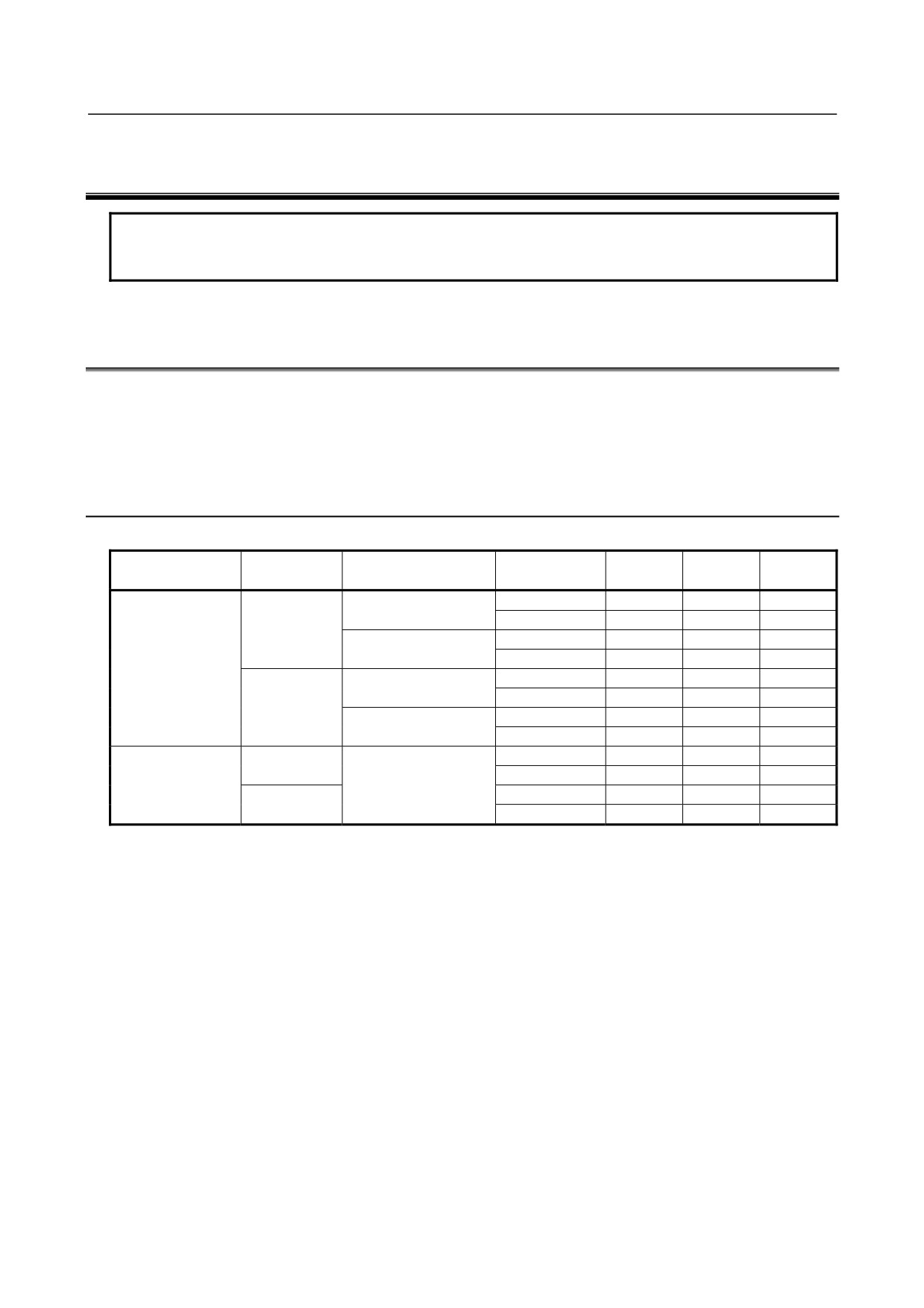
Control units (A circle indicates that the corresponding unit is available.)
Expansion
Display unit
Touch panel
MDI
Soft key
0i
0i Mate
slot
LCD-mounted type
Absent
5+2
Available
Available
(Horizontal)
2
5+2
Available
N/A
Absent
LCD-mounted type
Absent
5+2
Available
Available
8.4-inch
(Vertical)
2
5+2
Available
N/A
color LCD
LCD-mounted type
Absent
5+2
Available
Available
(Horizontal)
2
5+2
Available
N/A
Present
LCD-mounted type
Absent
5+2
Available
Available
(Vertical)
2
5+2
Available
N/A
Absent
10+2
Available
N/A
Absent
10.4-inch
Stand-alone type
2
10+2
Available
N/A
color LCD
(Vertical / Horizontal)
Absent
Absent
Available
N/A
Present
2
Absent
Available
N/A
For the 8.4-inch color LCD, the touch panel is attached to only lathe system CNCs.
- 1 -

1.CONFIGURATION
B-64303EN/03
Control unit
MDI
LCD
(See Section 5.1)
Memory card
Soft key
interface
NOTE
This figure is a front view of the 8.4-inch color LCD/MDI (horizontal) type control
unit.
- 2 -
B-64303EN/03
1.CONFIGURATION
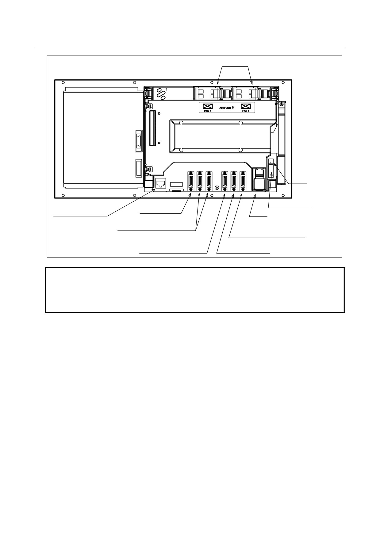
Control unit
Fan unit
Rear of unit
Fuse
MDI connector
Power supply connector [CP1]
Ethernet connector
[JA2]
[CD38A](See Section 5.4.)
Battery
I/O device interface connector
Serial spindle connector or position
[JD36A(left)/JD36A(right)]
coder connector
[JA41] (See Section 6.1 or 6.3.)
Analog spindle connector or
high-speed skip connector
I/O-Link connector
[JA40] (See Section 5.3 or 6.2.)
[JD51A] (See Chapter 9.)
NOTE
This figure is a rear view of the control unit without option slots.
The numbers in parentheses () in the figures are keyed to the item numbers of
the descriptions in this manual. The numbers in brackets [] in the figures are
connector numbers.
- 3 -
1.CONFIGURATION
B-64303EN/03
(See Chapter 9.)
(See Chapter 9.)
(See Chapter 9.)
(See Chapter 9.)
(See Chapter 9.)
- 4 -
B-64303EN/03
1.CONFIGURATION
1.2
HARDWARE OVERVIEW
1.2.1
Control Unit Overview
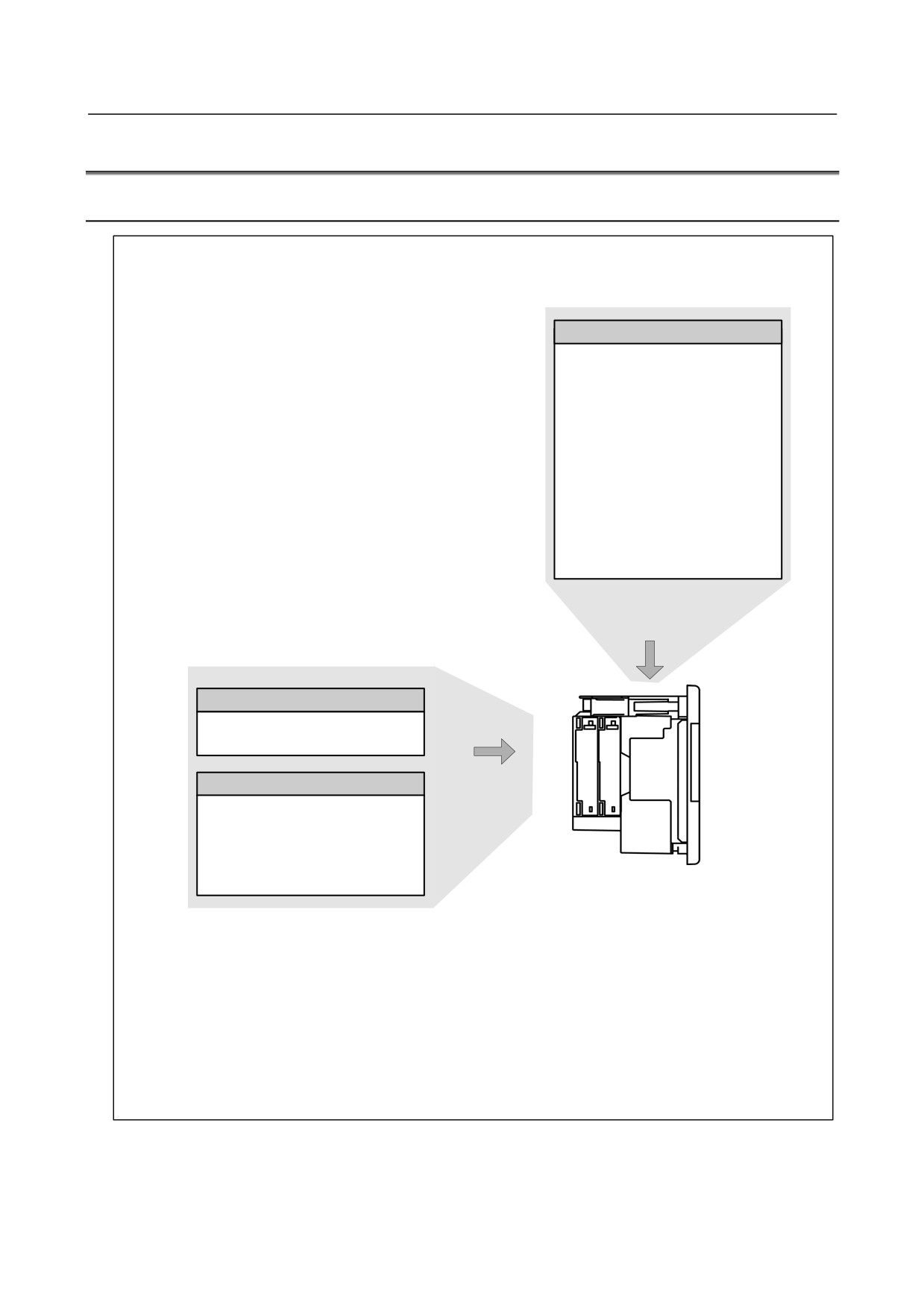
Main board
• CPU for controlling CNC
• Power supply
• Axis control
• Spindle interface
• LCD/MDI interface
• I/O Link
• PMC control function
• High-speed DI
• RS-232C
• Memory card interface
• Ethernet (Series 0i only)
Basic system
Fast Ethernet board
Data server function
Ethernet communication function
Various types of network boards
Options
Profibus master board
Profibus slave board
FL-net board
DeviceNet master board
DeviceNet slave board
Unit without optional slots
or
Unit having two optional slots
The control unit of the Series 0i Mate has no optional slots, so no option board can be inserted.
A unit with optional slots can have as many option boards as option slots.
The Fast Ethernet board can be inserted into only the slot on the LCD side.
- 5 -
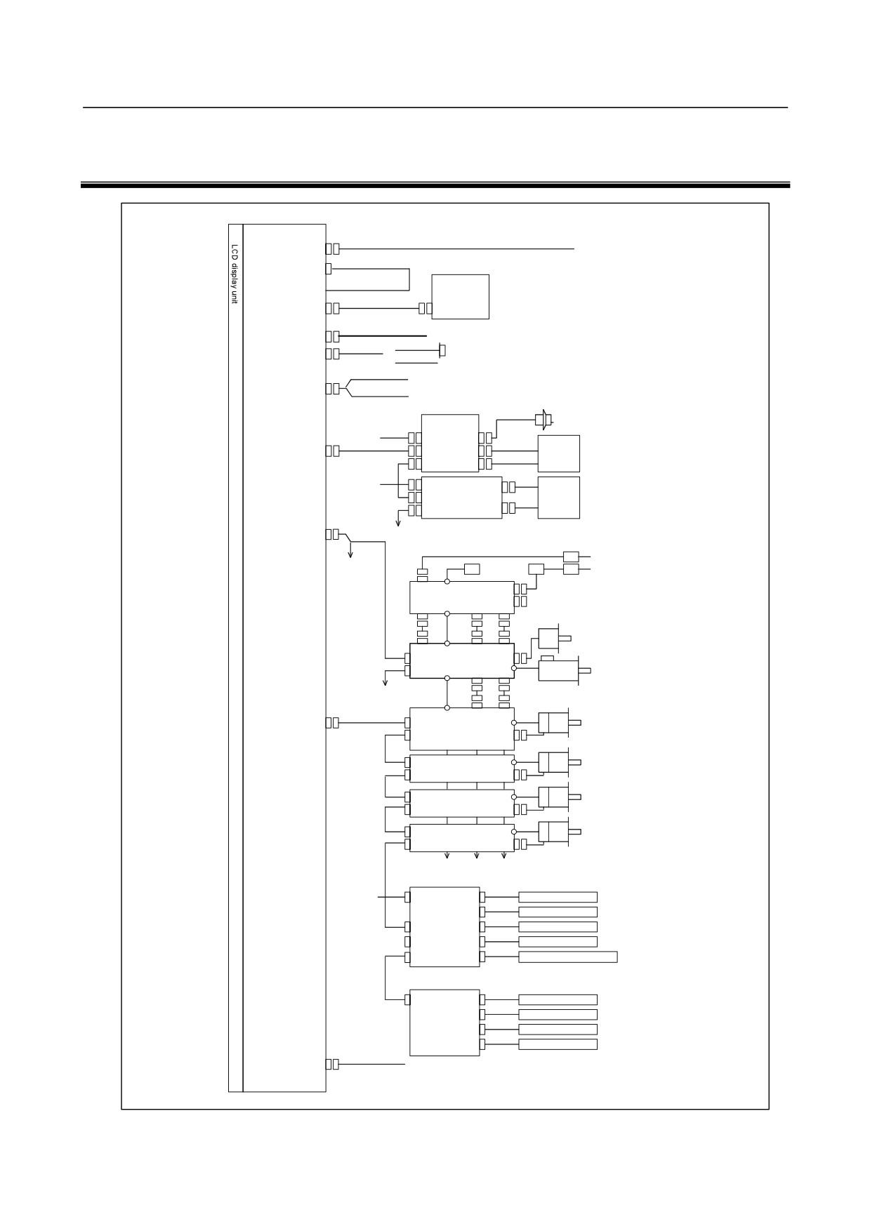
2.TOTAL CONNECTION DIAGRAMS
B-64303EN/03
2 TOTAL CONNECTION DIAGRAMS
LCD-mounted type control unit
Main board
24V-IN(CP1)
24 VDC power supply
(CA122)
Soft key cable
MDI UNIT
MDI(JA2)
CK1
R232-1(JD36A)
RS-232-C I/O device
R232-2(JD36B)
{
RS-232-C I/O device
Touch panel
Analog output for tool drives
A-OUT&HDI(JA40)
High-peed skip input
Distributed I/O
Manual pulse generator
board
24VDC
CPD1
JA3
I/O Link(JD51A)
JD1B
Operator's
JD1A
panel
24VDC
CPD1
Distributed
Power
JD1B
I/O board,
magnetics
I/O unit, etc.
JD1A
cabinet
SPDL(JA41)
Circuit breaker
200VAC
To 3rd spindle
AC reactor
200VAC
MCC
Circuit breaker
αi PS
Position coder
αi SP
To 2nd spindle
Serial spindle motor
FSSB(COP10A)
COP10B
αi SV
Servo motor
COP10A
COP10B
αi SV
Servo motor
COP10A
COP10B
αi SV
Servo motor
COP10A
COP10B
αi SV
Servo motor
COP10A
(In this figure, a 1-axis amplifier is used.)
Separate detector interface unit 1
24VDC
CP11A
JF101
Linear scale, axis 1
JF102
Linear scale, axis 2
COP10B
JF103
Linear scale, axis 3
COP10AJF104
Linear scale, axis 4
CNF1
JA4A
Absolute scale battery
(Required only when an absolute scale is used)
Separate detector interface unit 2
CP11AJF101
Linear scale, axis 1
JF102
Linear scale, axis 2
JF103
Linear scale, axis 3
JF104
Linear scale, axis 4
ETHERNET(CD38A)
Ethernet
- 6 -
B-64303EN/03
2.TOTAL CONNECTION DIAGRAMS
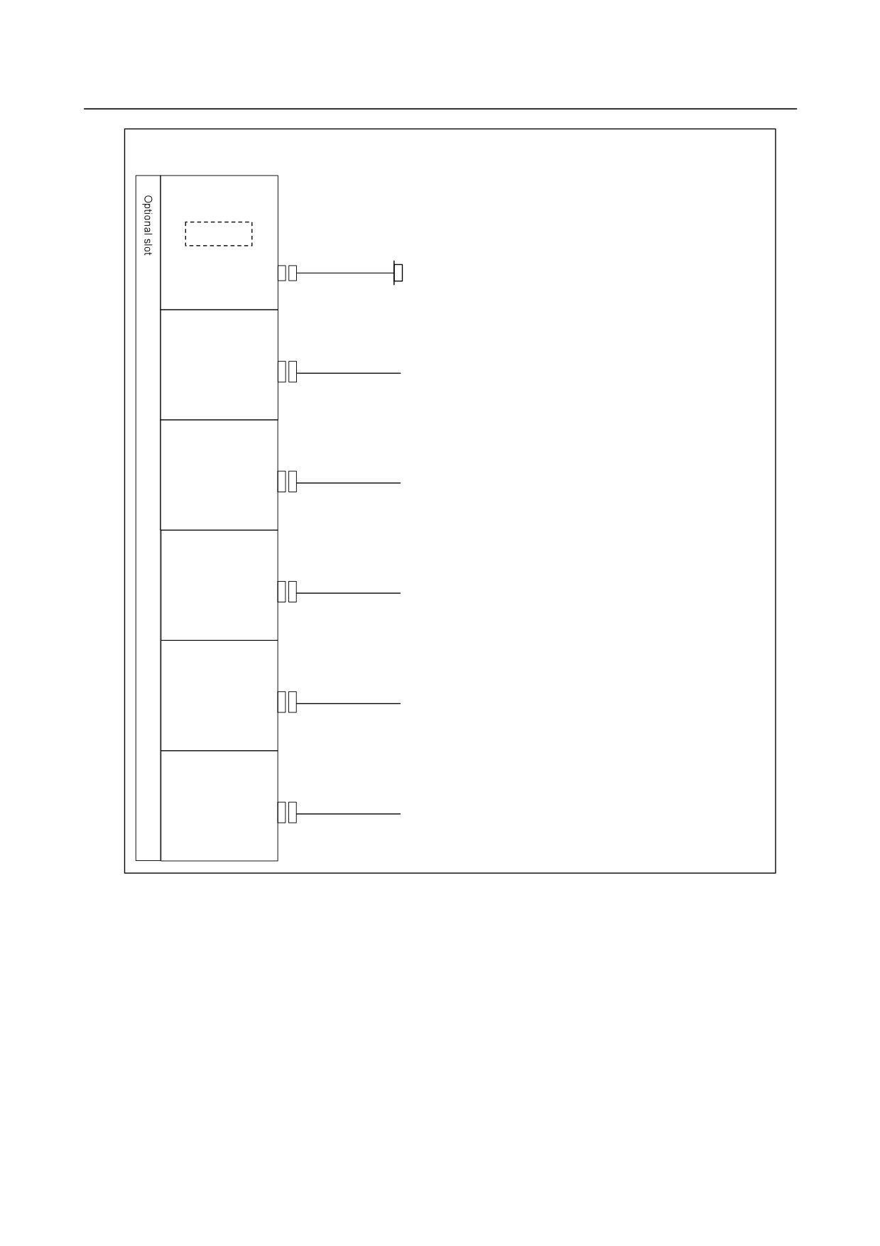
When optional functions are provided
Fast Ethernet board
Memory card
Prepare the memory card recommended by FANUC.
ETHERNET(CD38R)
Ethernet
PROFIBUS-DP
master board
PROFI(CN1)
Another NC or Profibus device
PROFIBUS-DP
slave board
PROFI(CN2)
Another NC or Profibus device
DeviceNet
master board
DVNET(TBL)
Another NC or Profibus device
DeviceNet
slave board
DVNET(TBL)
Another NC or Profibus device
FL-net board
FLNET(CD38N)
FL-net device
- 7 -
2.TOTAL CONNECTION DIAGRAMS
B-64303EN/03
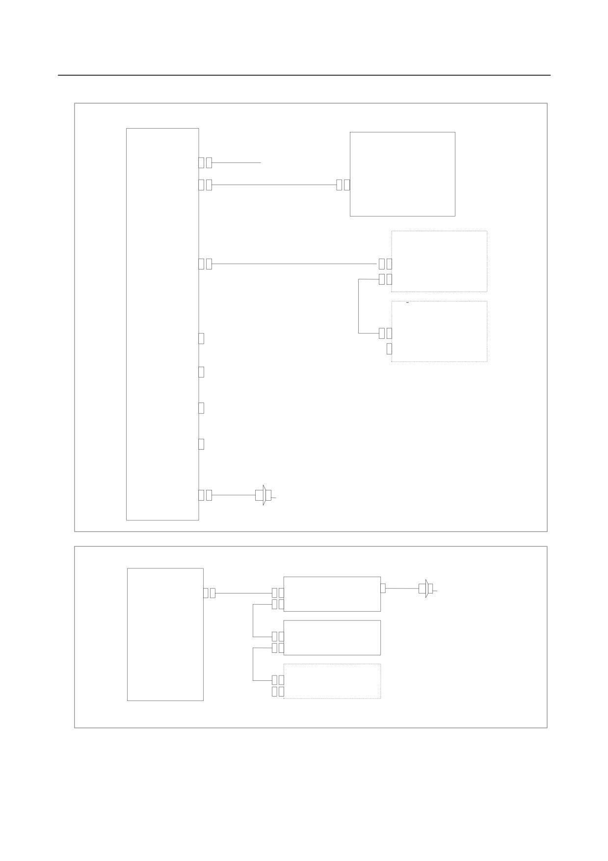
Example of I/O Link connection
Series 0i
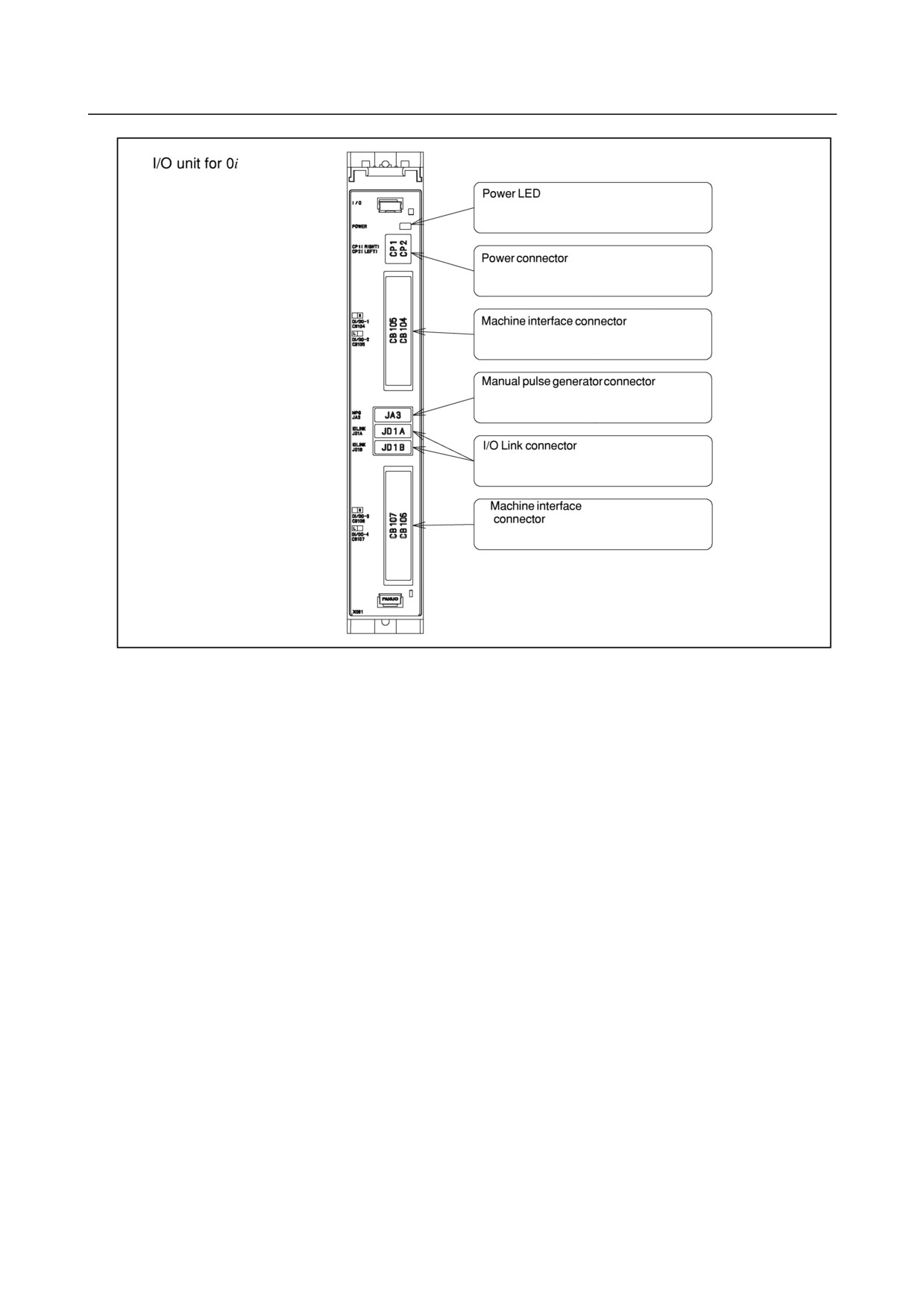
I/O Unit for 0i
Series 0i
Main board
(CP1)
24VDC
I/O Link (JD1B)
JD51A
I/O for operator’s
panel
I/O Link
I/O Link (JD1A)
JD1B
JD1A
DI : 96 points
DO : 64 points
I/O Link βi
servo amplifier
DI/DO-1
JD1B
(CB104)
JD1A
DI/DO-2
(CB105)
The order in which slave devices are
connected via I/O Link can be
DI/DO-3
determined freely.
(CB106)
DI/DO-4
(CB107)
MPG(JA3)
Manual pulse generator (up to three units)
Series 0i Mate
Series 0i Mate
I/O for operator’s panel(with MPG)
Main board
I/O Link
JD1B
JA3
Manual pulse generator
I/O Link (JD51A)
JD1A
(up to three units)
I/O for operator’s panel
(without MPG)
JD1B
JD1A
I/O Link βi servo
(For the 0i Mate, the number of connectable
amplifier
amplifiers depends on the model.)
The order in which slave devices are connected via
I/O Link can be determined freely.
- 8 -
B-64303EN/03
3.INSTALLATION
3 INSTALLATION
3.1
ENVIRONMENTAL REQUIREMENTS
3.1.1
Environmental Conditions External to Cabinets
The peripheral units and the control unit have been designed on the assumption that they are housed in
closed cabinets. In this manual "cabinet" refers to the following:
• Cabinet manufactured by the machine tool builder for housing the control unit or peripheral units;
• Operation pendant, manufactured by the machine tool builder, for housing the LCD/MDI unit or
operator's panel.
• Equivalent to the above.
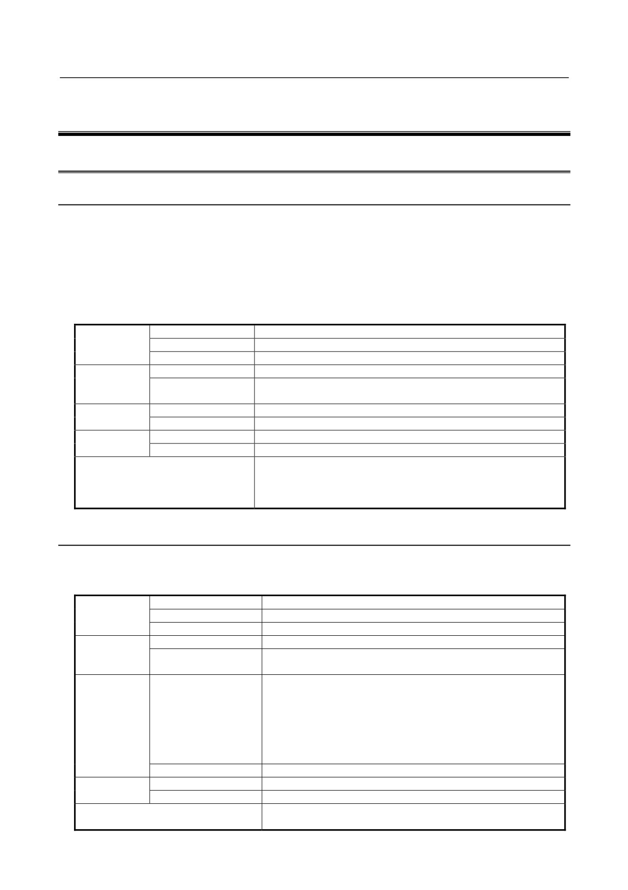
The environmental conditions when installing these cabinets shall conform to the following table.
Ambient
Operating
0°C to 45°C
temperature of
Storage, Transport
−20°C to 60°C
cabinets
Temperature change
0.3°C/minute or less
Normal
75%RH or less, no condensation
Humidity
Short period
95%RH or less, no condensation
(less than 1 month)
Operating
0.5G or less
Vibration
Non-operating
1.0G or less
Meters above
Operating
Up to 1000 m (Note)
sea level
Non-operating
Up to 12000 m
Normal machine factory environment (These conditions need to be
reviewed separately when the cabinets are installed in an environment
Environment
where the concentrations of dust, coolant, organic solvent, and
corrosive gases are relatively high.)
3.1.2
Environmental Conditions of the Control Unit
The environmental conditions for installing the control unit in the cabinets are shown in the following
table. Section
3.3 describes the installation and design conditions of a cabinet satisfying these
conditions.
Operating
0°C to 58°C
Ambient
Storage, Transport
−20°C to 60°C
temperature
Temperature change
0.3°C/minute or less
Normal
75%RH or less, no condensation
Humidity
Short period
95%RH or less, no condensation
(less than 1 month)
0.5G or less
A FANUC evaluation test is performed under the following conditions.
10 to 58Hz:
0.075 mm (amplitude)
Operating
58 to 500Hz:
1 G
Vibration
Vibration directions: X, Y, and Z directions
Scanning frequency:
10 cycles
IEC68-2-6 compliant
Non-operating
1.0G or less
Meters above
Operating
Up to 1000 m (Note)
sea level
Non-operating
Up to 12000 m
Prevent coolant, lubricant, and chippings from being applied directly
Environment
to on the control unit. Make sure that corrosive gas is not present.
- 9 -
3.INSTALLATION
B-64303EN/03
Normal machine factory environment (take protective measures when
Atmosphere outside the cabinet
the control unit is used in an environment where the concentration of
dust, coolant, organic solvent, corrosive gas is relatively high.)
NOTE
1 If the CNC is installed 1000 m or higher above sea level, the allowable upper
ambient temperature of the CNC in the cabinet is changed as follows.
Assume that the allowable upper ambient temperature of the CNC in the cabinet
installed 1000 m or higher above sea level decreases by 1.0°C for every 100 m
rise in altitude.
Example)
The upper allowable ambient temperature of the CNC in the cabinet installed
1750 m above sea level is:
58°C-(1750-1000)/100×1.0°C=50.5°C
Therefore, the allowable ambient temperature range is from 0°C to 50.5°C.
2 When using a unit for which the installation conditions are specified separately,
the conditions also need to be met.
3.2
POWER SUPPLY CAPACITY
3.2.1
Power Supply Capacities of CNC-related Units
The following CNC-related units require an input power supply that satisfies the indicated current
capacities with a power supply voltage of 24 VDC ±10%. Here, note that momentary voltage changes
and ripples are also within ±10% of the power supply voltage.
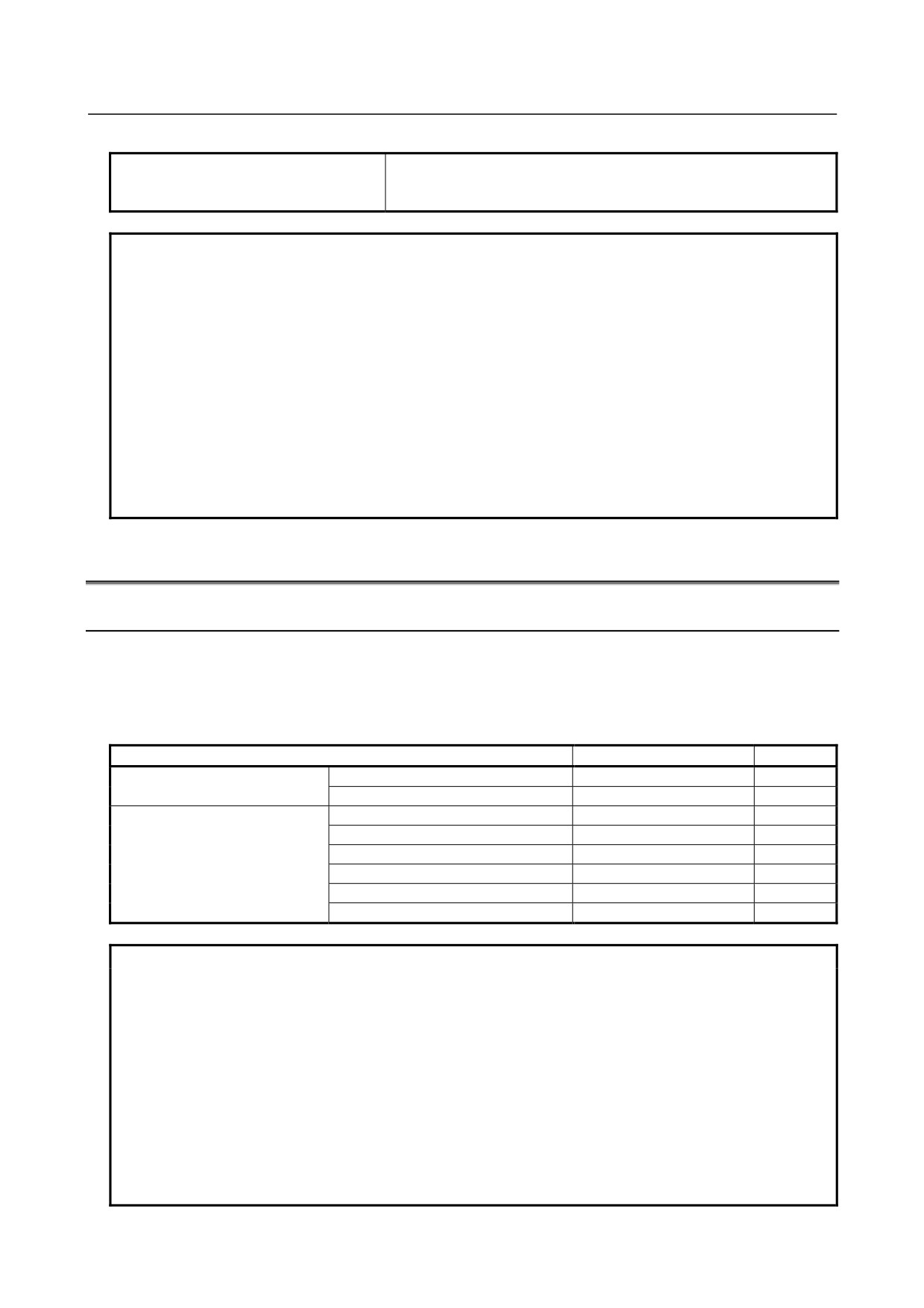
Table 3.2.1 (a) Power supply capacity
Unit
Power supply capacity
Remarks
Control unit
With no-optional slot
1.5A
Note 1)
With two optional slots
1.7A
Note 1)
Optional board
Fast Ethernet board
0.2A
Profibus master board
0.2A
Profibus slave board
0.1A
FL-net board
0.2A
DeviceNet master board
0.1A
DeviceNet slave board
0.1A
NOTE
1 The liquid-crystal display and MDI unit are included. Optional boards are not
included.
2 When connecting an RS-232-C unit (powered by the NC) to the RS-232-C port,
add the current capacity of the unit. Up to 1 A can be supplied from the two
channels of the port.
3 Use memory cards that consume no more than 2 W.
4 For other peripheral units (such as I/O units), see Table 3.2.1 (b) and also refer
to the relevant manuals.
5 When you select the input DC power supply for the CNC control section,
consider the restrictions other than the power supply capacity. Be sure to see
also Subsection 4.2.2.
- 10 -
B-64303EN/03
3.INSTALLATION
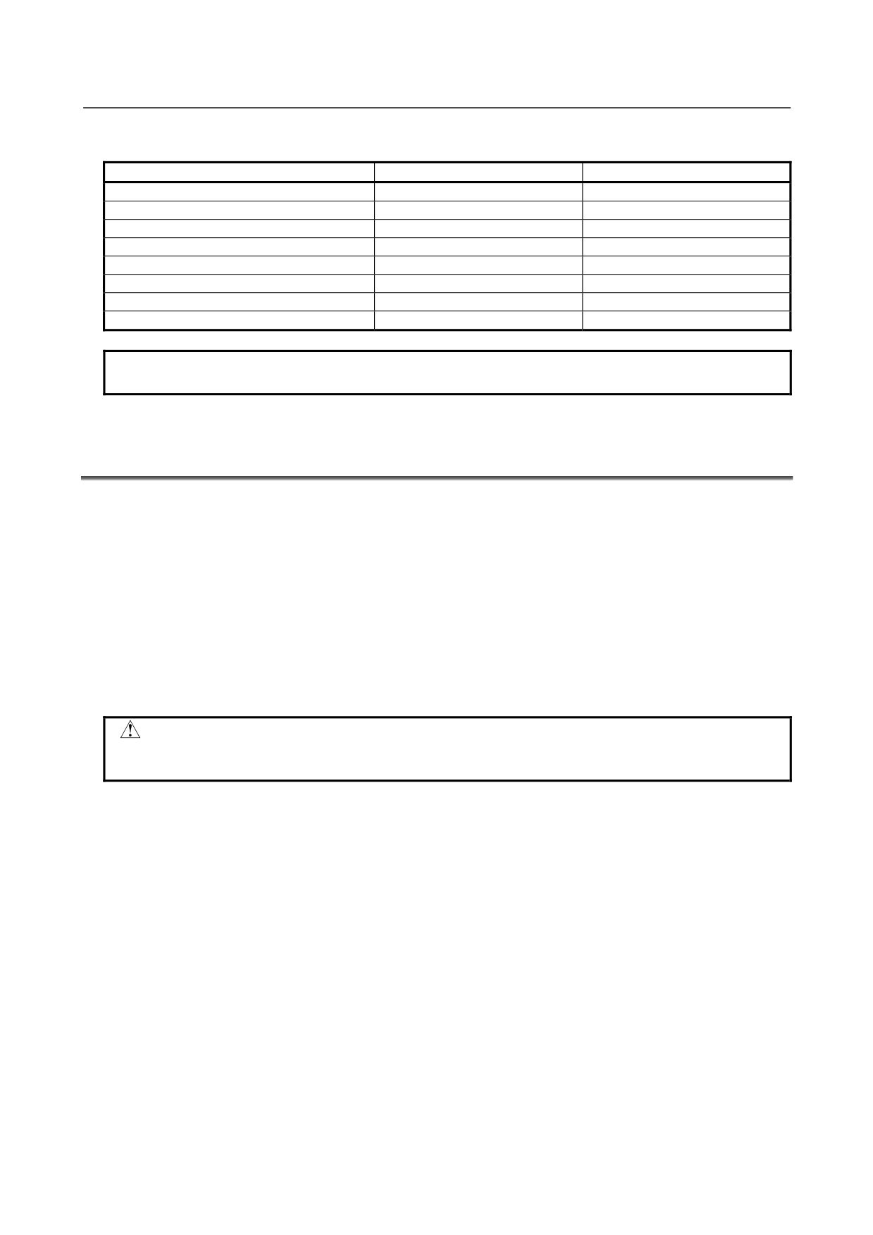
Table 3.2.1 (b) Power supply rating (peripheral units)
Unit
Power supply capacity
Remarks
MDI unit
0A
Standard machine operator’s panel
0.4A
Operator's panel I/O module
0.3A+7.3mA×DI
Connector panel I/O module (basic)
0.2A+7.3mA×DI
Connector panel I/O module (additional)
0.1A+7.3mA×DI
I/O unit for 0i
0.3A+7.3mA×DI
Separate detector interface unit
0.9A
Basic 4-axis unit only
Separate detector interface unit
1.5A
Basic 4 axes + additional 4 axes
NOTE
The power supply capacity for DO is not assumed for I/O units.
3.3
DESIGN AND INSTALLATION CONDITIONS OF THE
MACHINE TOOL MAGNETIC CABINET
When a cabinet is designed, it must satisfy the environmental conditions described in Section 3.1. In
addition, the magnetic interference on the screen, noise resistance, and maintenance requirements must be
considered. The cabinet design must meet the following conditions :
(1)
The cabinet must be fully closed.
The cabinet must be designed to prevent the entry of airborne dust, coolant, and organic solvent.
(2)
The cabinet must be designed so that the permissible temperature of each unit is not exceeded. For
actual heat design, see Section 3.4.
(3)
A closed cabinet must be equipped with a fan to circulate the air within.
(This is not necessary for
a unit with fan.)
The fan must be adjusted so that the air moves at 0.5 m/sec along the surface of each installed unit.
CAUTION
If the air blows directly from the fan to the unit, dust easily adheres to the unit.
This may cause the unit to fail.
(This is not necessary for a unit with fan.)
(4)
For the air to move easily, a clearance of 100 mm is required between each unit and the wall of the
cabinet.
(5)
Packing materials must be used for the cable port and the door in order to seal the cabinet.
(6)
The display unit must not be installed in such a place that coolant would directly fall onto the unit.
The control unit has a dust-proof front panel, but the unit should not be placed in a location where
coolant would directly fall onto it.
(7)
Noise must be minimized.
As the machine and the CNC unit are reduced in size, the parts that generate noise may be placed
near noise-sensitive parts in the magnetics cabinet.
The CNC unit is built to protect it from external noise. Cabinet design to minimize noise
generation and to prevent it from being transmitted to the CNC unit is necessary. See section 3.5
for details of noise elimination/management.
(8)
When placing units in the cabinet, also consider ease of maintenance.
The units should be placed so that they can be checked and replaced easily when maintenance is
performed.
(9)
The installation conditions of the I/O unit and connector panel I/O module must be satisfied.
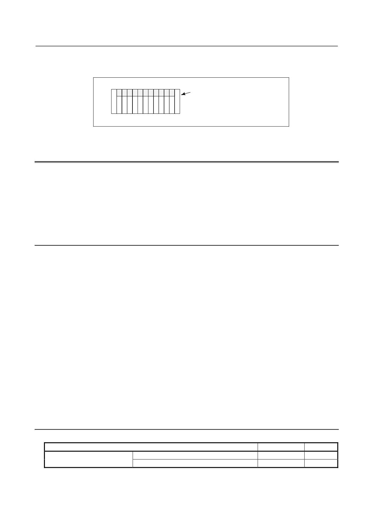
To obtain good ventilation in the module, the I/O unit and connector panel I/O module must be
installed in the direction shown in the following figure. Clearances of 100 mm or more both above
and below the I/O unit are required for wiring and ventilation.
- 11 -
3.INSTALLATION
B-64303EN/03
Equipment radiating too much heat must not be put below the I/O unit and connector panel I/O
module.
Top
Connector panel I/O module or
I/O base unit
(No screws or protrusions shall extend
from the bottom of this unit.)
Bottom
3.4
THERMAL DESIGN OF THE MACHINE TOOL MAGNETIC
CABINET
The internal air temperature of the cabinet increases when the units and parts installed in the cabinet
generate heat. Since the generated heat is radiated from the surface of the cabinet, the temperature of the
air in the cabinet and the outside air balance at certain heat levels.
If the amount of heat generated is
constant, the larger the surface area of the cabinet, the less the internal temperature rises. The thermal
design of the cabinet refers to calculating the heat generated in the cabinet, evaluating the surface area of
the cabinet, and enlarging that surface area by installing heat exchangers in the cabinet, if necessary.
Such a design method is described in the following subsections.
3.4.1
Temperature Rise within the Machine Tool Magnetic Cabinet
The cooling capacity of a cabinet made of sheet metal is generally 6 W/°C per 1m2 surface area, that is,
when the 6W heat source is contained in a cabinet having a surface area of 1 m2, the temperature of the air
in the cabinet rises by 1°C. In this case the surface area of the cabinet refers to the area useful in
cooling , that is, the area obtained by subtracting the area of the cabinet touching the floor from the total
surface area of the cabinet. There are two preconditions : The air in the cabinet must be circuited by the
fun, and the temperature of the air in the cabinet must be almost constant.
In the case of the operator's panel cabinet for example, to limit the temperature within the operator's panel
cabinet to 58°C or less when the ambient temperature is 45°C, satisfy the following expression.
Internal heat loss P [W] ≤
6[W/m2⋅°C] × surface area S[m2] × 13[°C] of rise in temperature
(A cooling capacity of 6 W/°C assumes the cabinet is so large that agitation with the fan motor does not
make the temperature distribution uniform. For a small cabinet like the operator's panel, a cooling
capacity of 8 W/°C, indicated in Subsection 3.4.4, may be used.)
For example, a cabinet having a surface area of 4m2 has a cooling capacity of 24W/°C. To limit the
internal temperature increase to 13°C under these conditions, the internal heat must not exceed 312W.
If the actual internal heat is 360W, however, the temperature in the cabinet rises by 15°C or more.
When this happens, the cooling capacity of the cabinet must be improved using the heat exchanger.
In the case of the power magnetics cabinet for housing cabinet the I/O unit for 0i, limit the internal
temperature increase to 10°C or less, not 13°C or less.
3.4.2
Heat Output of Each Unit
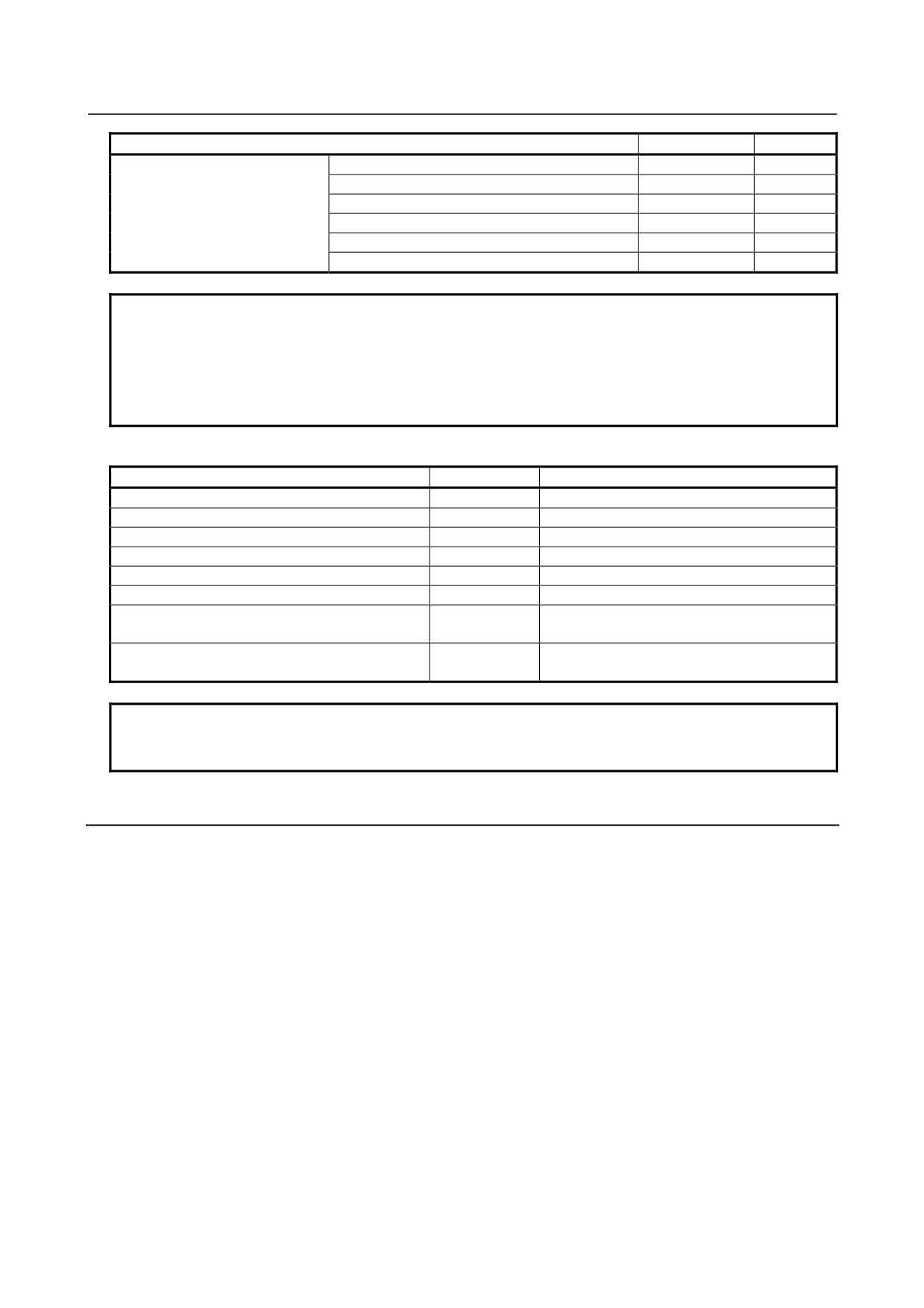
Table 3.4.2 (a) Heat output
Unit
Heat output
Remarks
Control unit
With no-optional slot
33W
Note 1)
With two optional slots
37W
Note 1)
- 12 -
B-64303EN/03
3.INSTALLATION
Unit
Heat output
Remarks
Optional board
Fast Ethernet board
6W
Note 2)
Profibus master board
5W
Profibus slave board
2W
FL-net board
5W
DeviceNet master board
3W
DeviceNet slave board
3.5W
NOTE
1 The liquid-crystal display and MDI unit are included. Optional boards are not
included.
2 When installing the CF card on the Fast Ethernet board, add 0.3 W for the Fast
Ethernet board to the heat output.
(The heat output of the CF card may be
changed if its specification is changed.)
Table 3.4.2 (b) Heat output
Unit
Heat output
Remarks
MDI unit
0W
Standard machine operator’s panel
15W
Note 1)
Operator's panel I/O module
12W
Note 1)
Connector panel I/O module (basic)
8W
Note 1)
Connector panel I/O module (additional)
5W
Note 1)
I/O unit for 0i
16W
Note 1)
Separate detector interface unit
9W
Basic 4-axis unit only
Note 2)
Separate detector interface unit
14W
Basic 4 axes + additional 4 axes
Note 2)
NOTE
1 The indicated values are when 50% of the module input signals are ON.
2 Heat output generated within the separate detector is not included.
3.4.3
Thermal Design of Operator's Panel
With a small cabinet like the operator's panel, the heat dissipating capacity of the cabinet is as shown
below, assuming that there is sufficient mixing of the air inside the cabinet.
Coated metal surfaces:
8 W/m2°C
Plastic surfaces:
3.7 W/m2°C
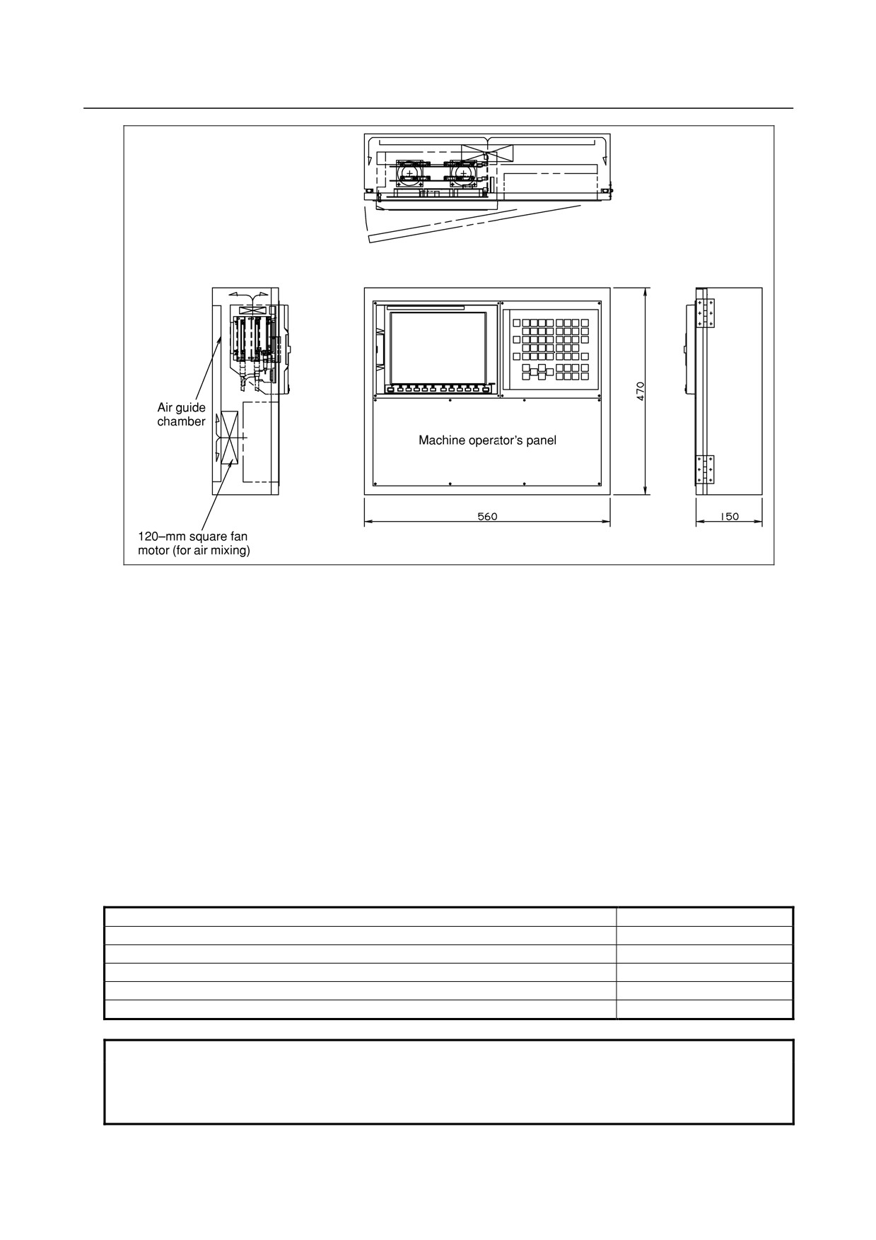
An example of the thermal design for the cabinet shown in Fig. 3.4.3 is shown below.
- 13 -
3.INSTALLATION
B-64303EN/03
Fig. 3.4.3
Assume the following.
Thermal exchange rates
Coated metal surfaces
:
8 W/m2⋅°C
Plastic surfaces
:
3.7 W/m2⋅°C
Allowable temperature rise
:
13°C higher than the exterior temperature
Also, assume the following.
Dimensions of pendant type cabinet shown in Fig. 3.4.3
:
560(W) × 470(H) × 150(D) mm
Surface area of metallic sections
:
0.5722 m2
Surface area of plastic sections
:
0.2632 m2
In this case, the allowable total heat dissipation for the cabinet is:
8 × 0.5722 × 13 + 3.7 × 0.2632 × 13 = 72 W.
In consequence, it can be concluded that the units shown in Table 3.4.3 on the next page can be installed
in this cabinet.
Table 3.4.3
Control unit (Optional two-slots)
37W
Optional board (Fast data server board)
3W
Optional board (Profibus master board)
5W
Standard machine operator's panel
15W
120-mm square fan motor for air mixing
8W
Total heat dissipation of the above
68W
NOTE
The 15 W quoted for the standard machine operator's panel represents an
example heat output value when half of all the input signals are turned on. This
value varies, depending on the mechanical configuration.
- 14 -
B-64303EN/03
3.INSTALLATION
3.5
COUNTERMEASURES AGAINST NOISE
The CNC has been steadily reduced in size using surface-mount and custom LSI technologies for
electronic components. The CNC also is designed to be protected from external noise. However, it is
difficult to measure the level and frequency of noise quantitatively, and noise has many uncertain factors.
It is important to prevent both noise from being generated and generated noise from being introduced into
the CNC. This precaution improves the stability of the CNC machine tool system.
The CNC component units are often installed close to the parts generating noise in the power magnetics
cabinet. Possible noise sources into the CNC are capacitive coupling, electromagnetic induction, and
ground loops.
When designing the power magnetics cabinet, guard against noise in the machine as described in the
following section.
3.5.1
Grounding
Grounding the power magnetics cabinet and devices is very important to prevent an electric shock and
suppress a noise influence. The following describes the grounding methods for suppressing the noise
influence.
3.5.1.1 About grounding types
The CNC system uses the following three types of grounding:
(1) Signal grounding
This type of grounding is used to supply a reference potential (0 V) for the electrical signal system.
(2) Frame grounding
This type of grounding is used for safety reasons as well as to suppress external and internal noise.
For example, grounding is provided for the device frames, panels, and shielding on the interface
cables connecting the devices.
(3) System grounding (PE)
This type of grounding is used to connect frame grounds, which are provided for the individual
devices or between the units, to the ground as a system at a single point.
3.5.1.2 Grounding methods
Typically, noise that becomes a problem is high-frequency noise. To suppress high-frequency noise, it is
important that the devices are grounded at low impedance(NOTE).
The grounding schemes for this purpose are described below.
(1) Multipoint grounding scheme
In this grounding scheme, when grounded at sufficiently low impedance, the cabinet metal plates are
used as ground plates, to which grounding is provided in the vicinity of each device.
This scheme has a great effect of suppressing high-frequency noise because it enables grounding to
the low-impedance metal plates of the cabinet in the shortest distance. However, the noise
suppression effect depends on the cabinet structure because the cabinet metal plates are used as
ground plates.
See Subsection 3.5.1.4 for the cabinet. Fig. 3.5.1.2 (a) is a schematic wiring diagram.
When the multipoint grounding scheme is adopted, the units can be grounded at low impedance, and
ground wires can be shortened, so that wiring may be simplified.
- 15 -
3.INSTALLATION
B-64303EN/03
(2) Single-point grounding scheme
In this grounding scheme, grounding separation is achieved between the signal system and power
system, and grounding is provided at a single point to suppress the noise influence of the power
system on the signal system.
This scheme tends to need longer connection wires for grounding the devices. To produce a
sufficient effect of suppressing high-frequency noise, it is therefore necessary to use larger-diameter
wires or use two or more wires for each connection. Fig. 3.5.1.2 (b) is a schematic wiring diagram.
NOTE
Impedance includes a resistance component that converts electric current to
heat as well as a component called “reactance”, and indicates a characteristic of
resistance to the flow of alternating current at a certain frequency.
- 16 -