FANUC Series 0i-MODEL D, Series 0i Mate-MODEL D. CONNECTION MANUAL (HARDWARE) - page 11
B-64303EN/03
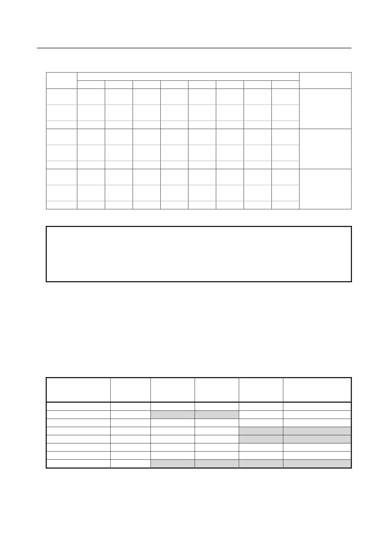
9.CONNECTION OF I/O Link SLAVE DEVICES
9.11.2.7 Applicable wire
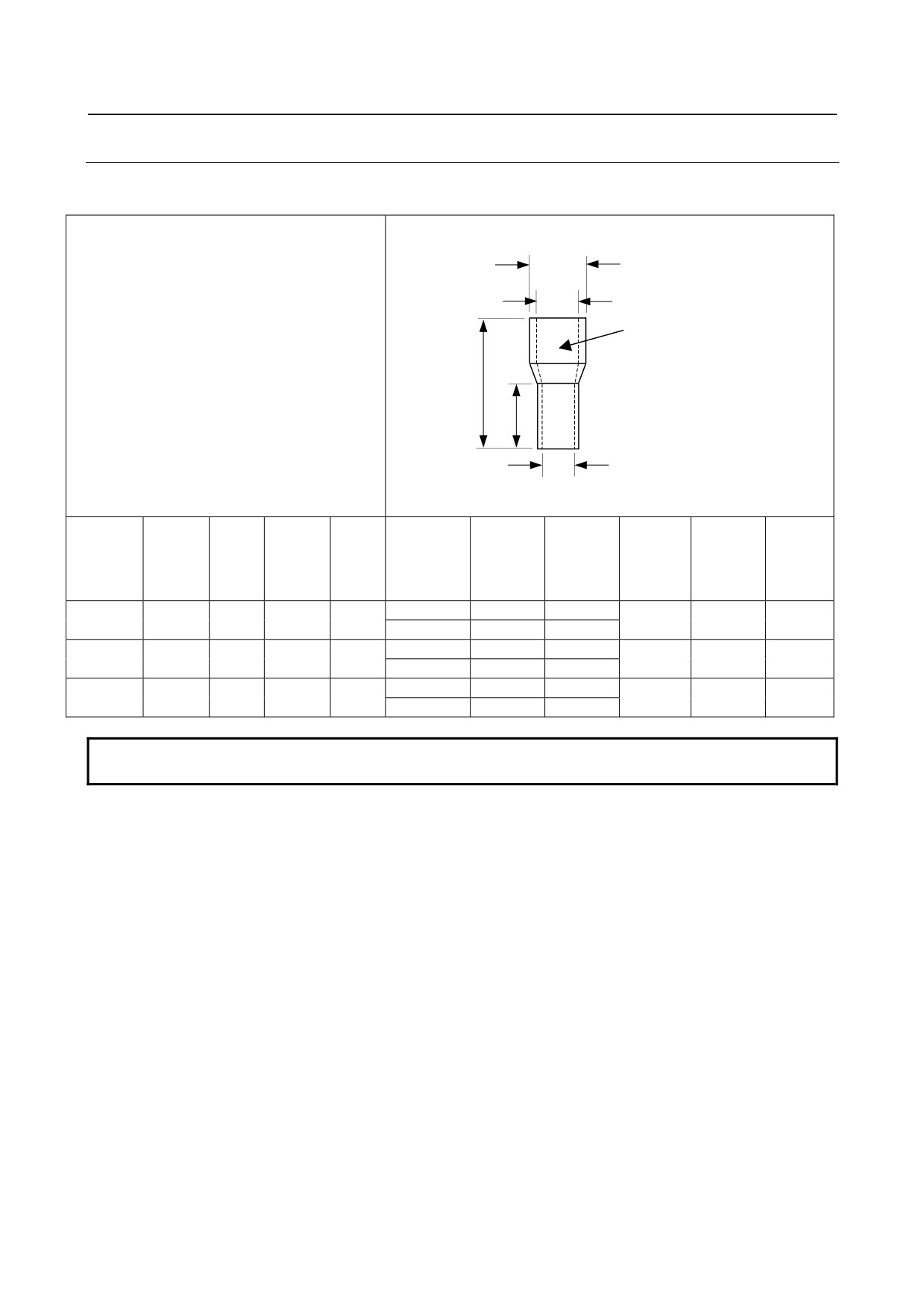
Electric wires and ferrule terminals used for connection with a terminal block of this module should have
the following dimensions:
Electric wire size
Ferrule terminal
φD3
φD2
Insulation cover
L
L2
φD1
The dimensions indicated below are based on the products of
Weidmuller Color., Ltd.
Cross sec-
Inner
Outer
Electric wire
Length of
Inner
tional area
JIS VSF
UL1007
UL1015
Overall
diameter of
diam-
JIS IV
sheath stripped
metallic
diameter
of electric
KIV
length
length
con-
eter of
(mm2)
part
of sheath
wire
ductor
(mm2)
(AWG)
(AWG)
(mm)
L1 (mm)
sheath
(mm2)
L2 (mm)
D2 (mm)
D1 (mm)
D3 (mm)
10
14
8
0.5
-
-
20
-
1
2.6
3.1
12
16
10
10
14
8
0.75
0.5
-
18
20
1.2
2.8
3.3
12
16
10
10
14
8
1.0
0.75
0.9
-
18
1.4
3
3.5
12
16
10
NOTE
Use a ferrule terminal from the viewpoint of long-term reliability.
- 287 -
9.CONNECTION OF I/O Link SLAVE DEVICES
B-64303EN/03
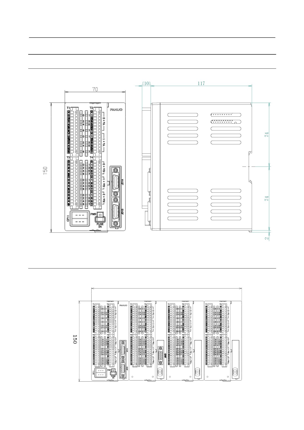
9.11.3 External View and Dimensions
9.11.3.1 Dimensions (common to the modules)
Unit: mm
9.11.3.2 Dimensions in a maximum configuration (one basic module +
three expansion modules)
Unit: mm
280
- 288 -
B-64303EN/03
9.CONNECTION OF I/O Link SLAVE DEVICES
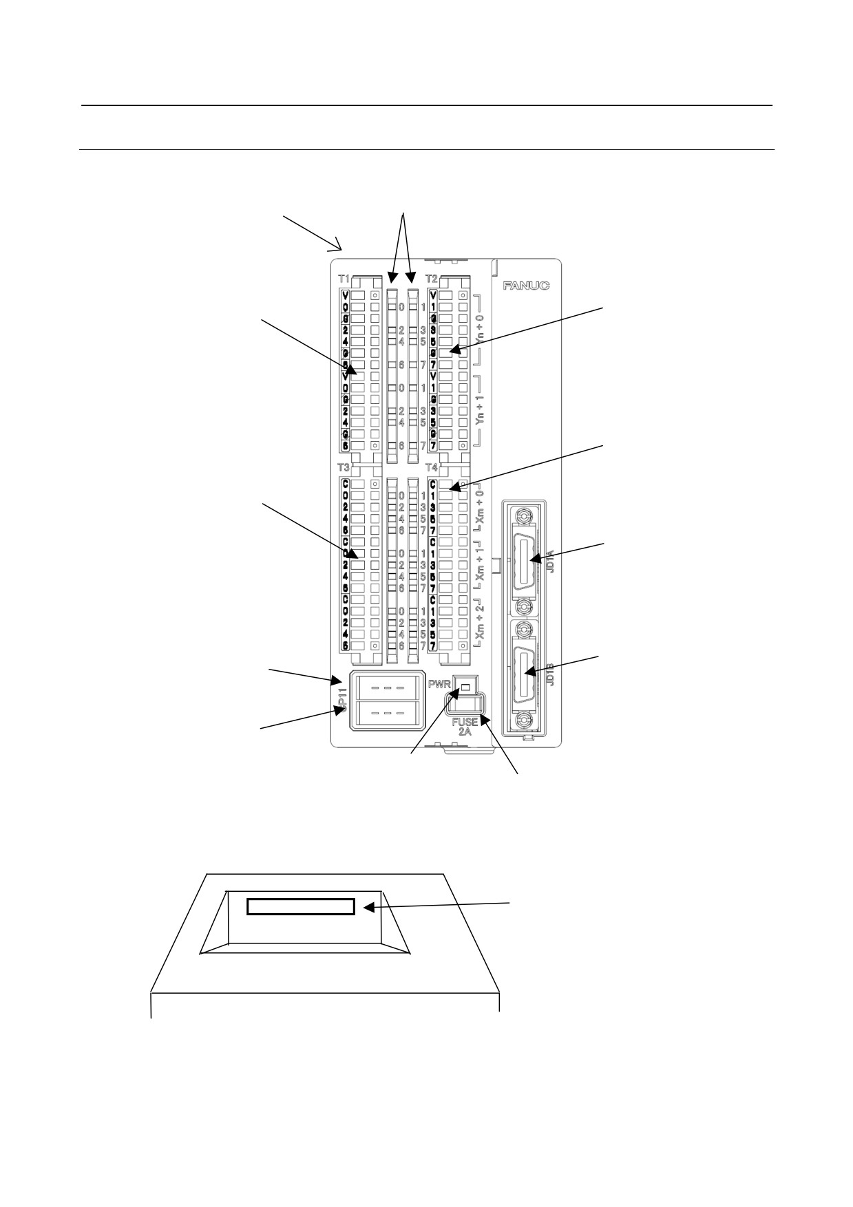
9.11.3.3 Component names
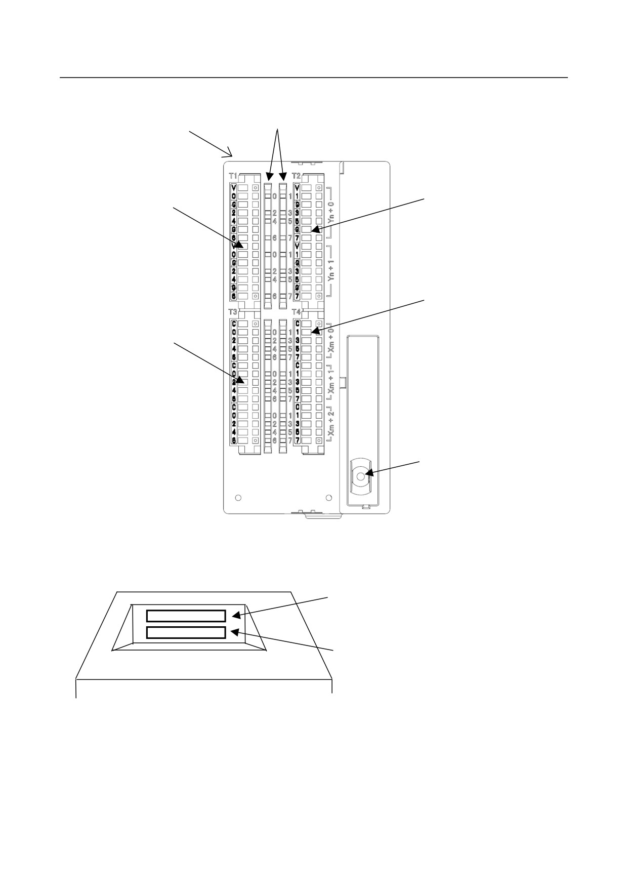
Basic module (A03B-0823-C001)
DI/DO state indication LED
A (See the figure below.)
DO terminal block T2
DO terminal block T1
Label color: Yellow green
Label color: Light blue
DI terminal block T4
Label color: Pink
DI terminal block T3
Label color: Yellow
JD1A (I/O LINK)
JD1B (I/O LINK)
Power input: CP11A
Power branching: CP11B
Power state
Fuse 2A
indication LED
View from A
Connector for expansion module
connection: CA105
- 289 -
9.CONNECTION OF I/O Link SLAVE DEVICES
B-64303EN/03
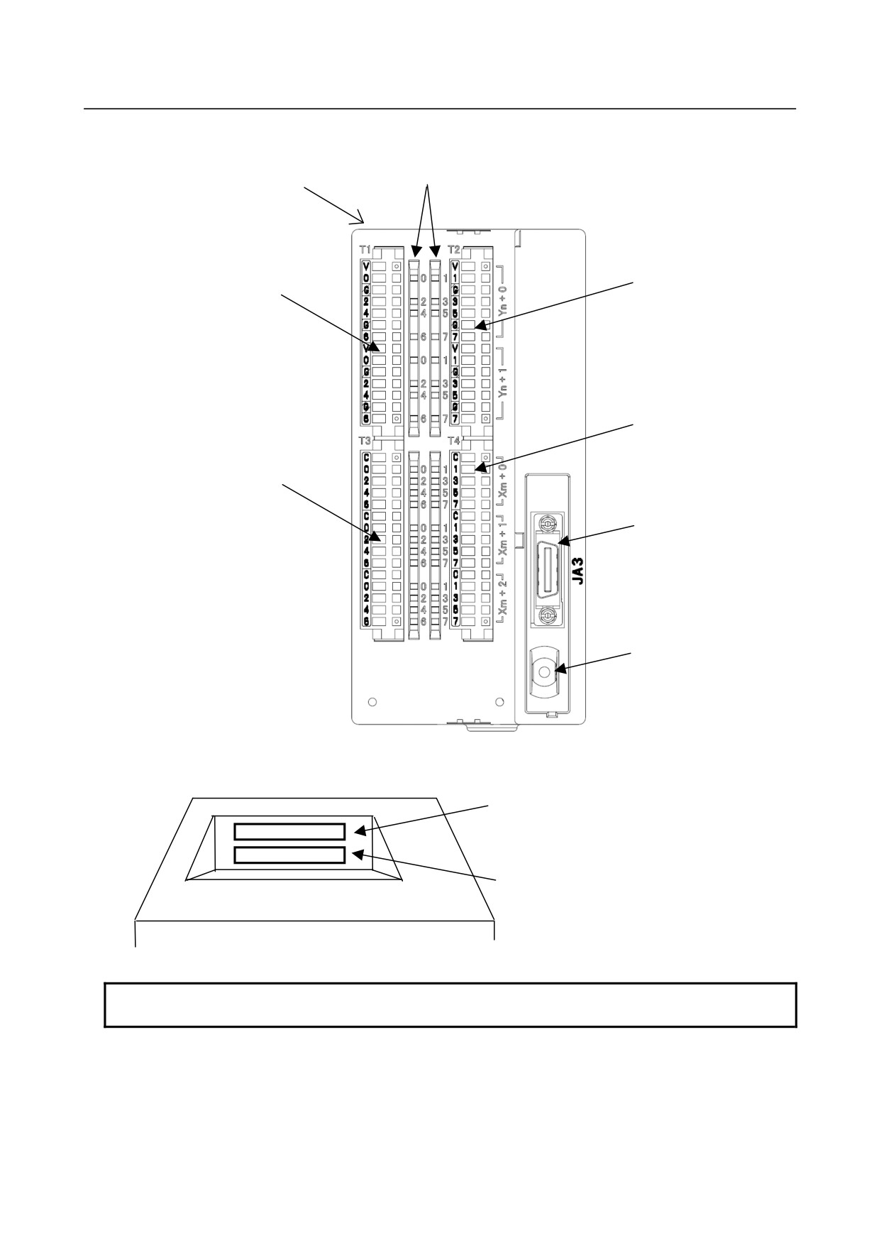
Expansion module A (A03B-0823-C002)
DI/DO state indication LED
A (See the figure below.)
DO terminal block T2
DO terminal block T1
Label color: Yellow green
Label color: Light blue
DI terminal block T4
Label color: Pink
DI terminal block T3
Label color: Yellow
JA3 (MPG)
Rotary switch
View from A
Connector for expansion module
connection: CA105
(To expansion module B at next stage)
Connector for expansion module
connection: CA106
(To basic module at preceding stage)
NOTE
Be sure to connect expansion module A beside the basic module.
- 290 -
B-64303EN/03
9.CONNECTION OF I/O Link SLAVE DEVICES
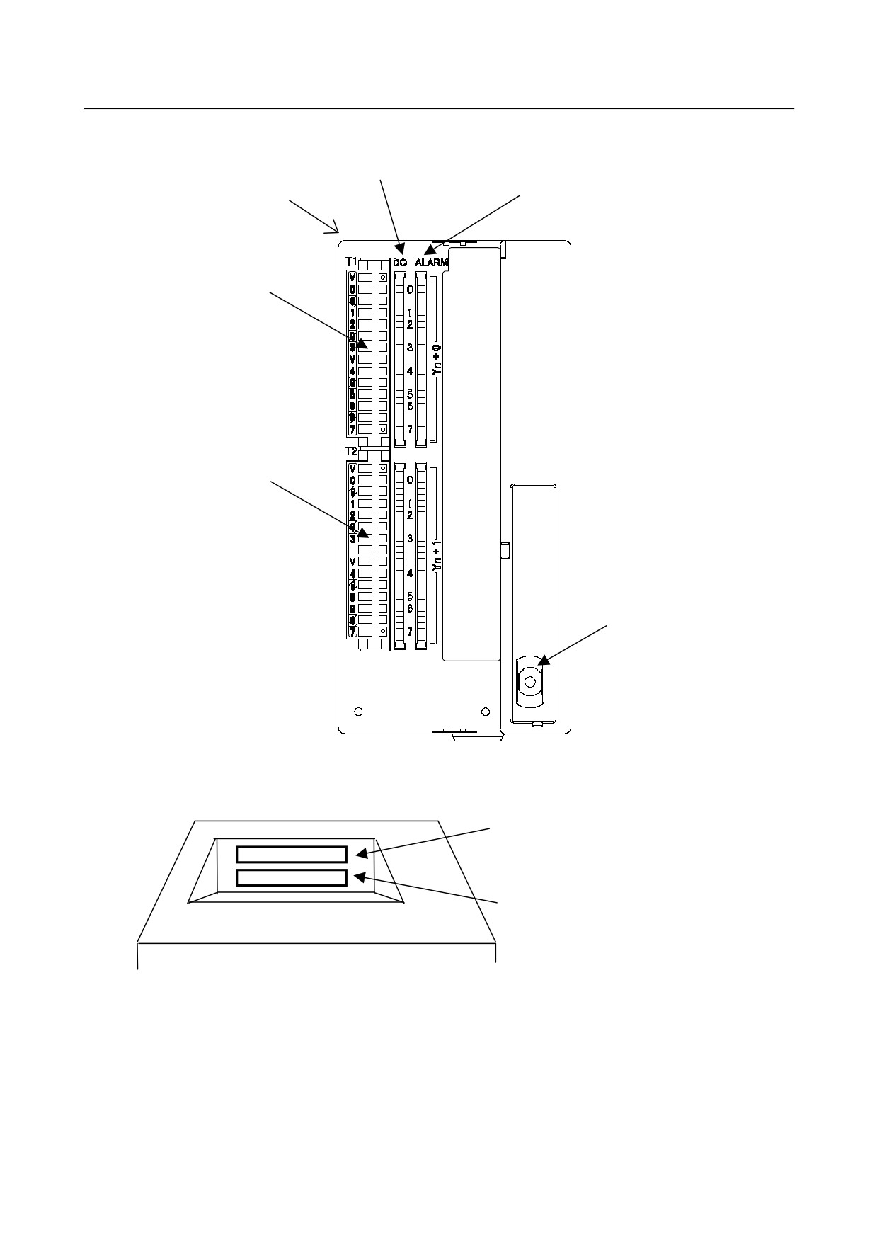
Expansion module B (A03B-0823-C003)
DI/DO state indication LED
A (See the figure below.)
DO terminal block T1
DO terminal block T2
Label color: Light blue
Label color: Yellow green
DI terminal block T4
Label color: Pink
DI terminal block T3
Label color: Yellow
Rotary switch
View from A
Connector for expansion module
connection: CA105
(To expansion module at next stage)
Connector for expansion module connection:
CA106
(To basic module or expansion module at
preceding stage)
- 291 -
9.CONNECTION OF I/O Link SLAVE DEVICES
B-64303EN/03
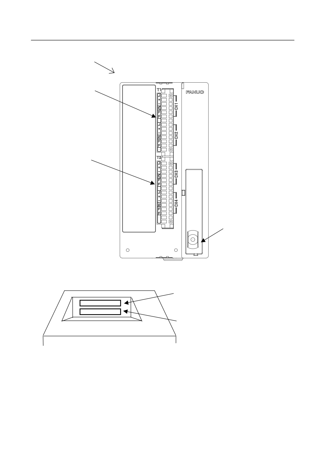
Expansion module C (A03B-0823-C004)
DO state indication LED (green)
A (See the figure below.)
DO alarm indication LED (red)
DO terminal block T1
Label color: Light blue
DO terminal block T2
Label color: Yellow green
Rotary switch
View from A
Connector for expansion module
connection: CA105
(To expansion module at next stage)
Connector for expansion module connection:
CA106
(To basic module or expansion module at
preceding stage)
- 292 -
B-64303EN/03
9.CONNECTION OF I/O Link SLAVE DEVICES
Expansion module D (A03B-0823-C005)
A (See the figure below.)
Terminal block for analog input
on CH1/CH2
T1
Label color: Yellow
Terminal block for analog
input on CH3/CH4
T2
Label color: Pink
Rotary switch
View from A
Connector for expansion module
connection: CA105
(To expansion module at next stage)
Connector for expansion module connection :
CA106
(To basic module or expansion module at
preceding stage)
- 293 -
9.CONNECTION OF I/O Link SLAVE DEVICES
B-64303EN/03
9.11.4 Installation
Notes on installation
1) Use a module in a completely sealed cabinet.
2) Be sure to install a module on a vertical plane and allow a clearance of 100 mm or more above and
below the module. Do not place a device that generates a large amount of heat below the module.
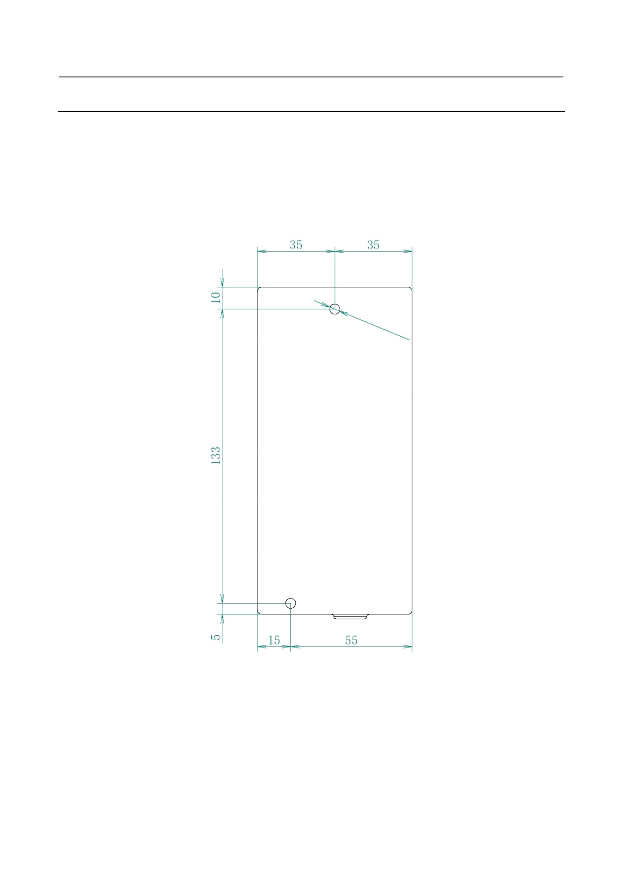
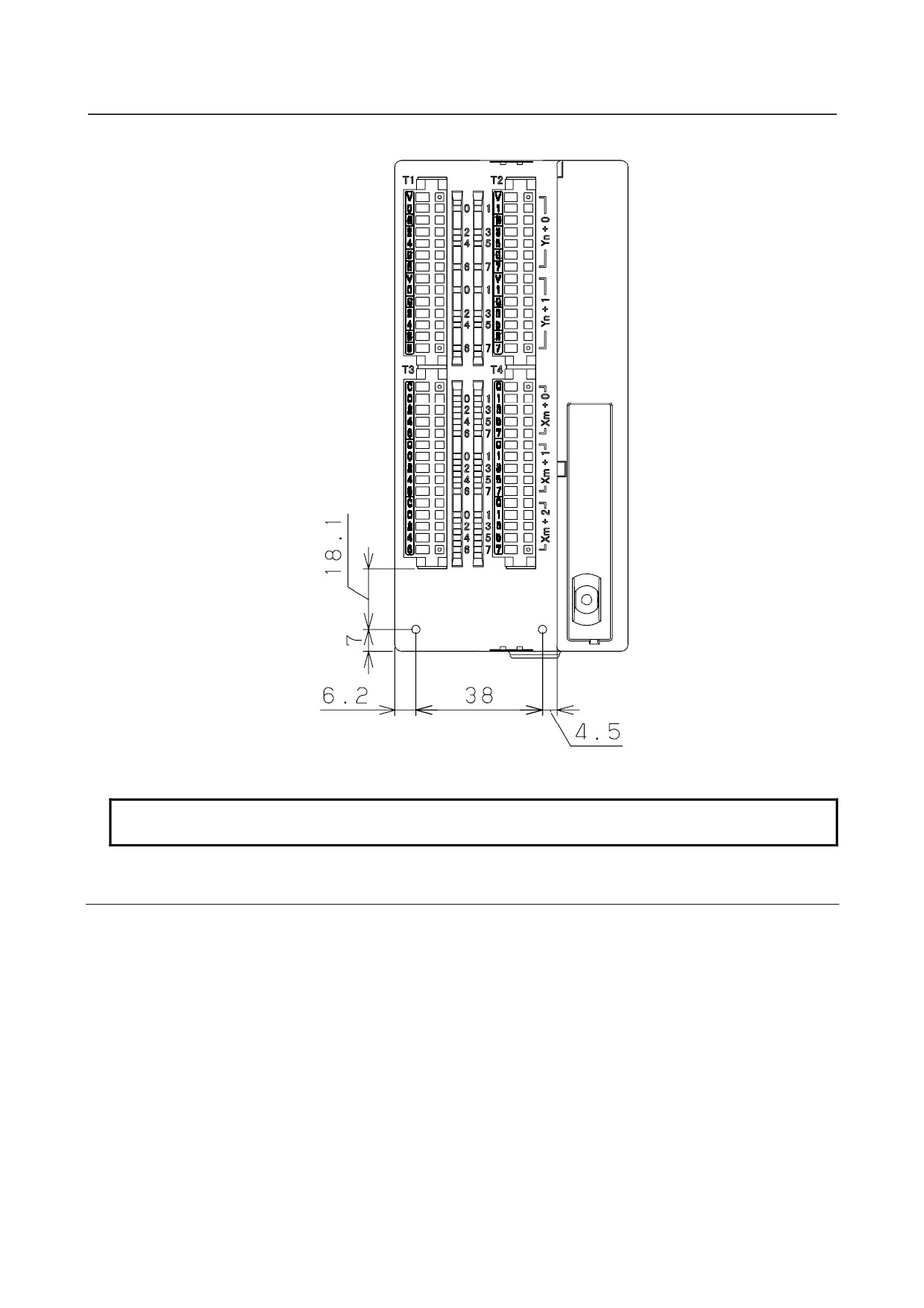
Mounting holes for screwing
Unit: mm
Front view of the module
2-M4
- 294 -
B-64303EN/03
9.CONNECTION OF I/O Link SLAVE DEVICES
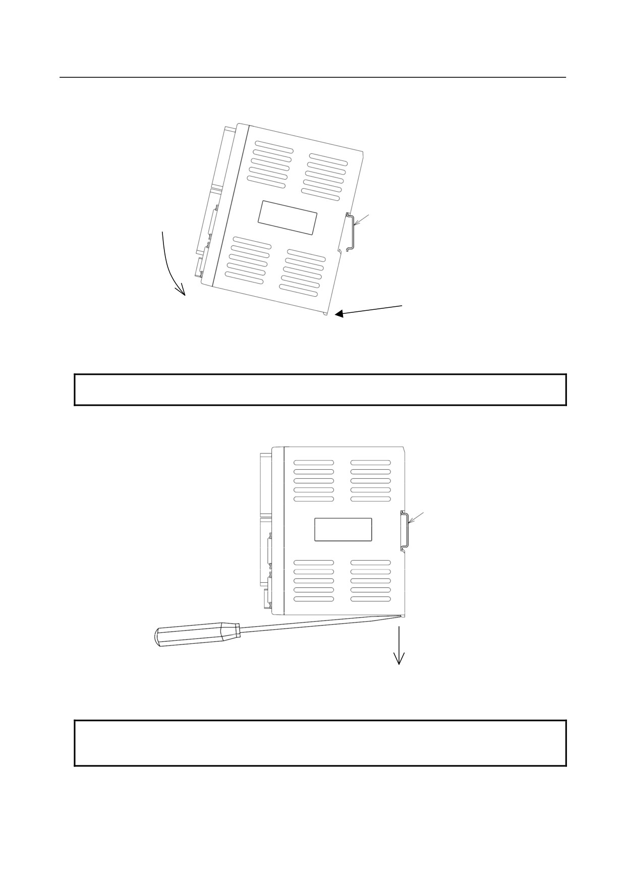
Using a DIN rail for mounting
1) Method of mounting
DIN rail
Locking section
1)
Place the hook of the module onto the top of the DIN rail.
2)
Push the module until it clicks into place.
NOTE
Ensure that the locking section is not left lowered.
2) Method of dismounting
DIN rail
1)
Lower the locking section with a flat-blade screwdriver.
2)
Pull the lower part of the module toward you.
NOTE
When dismounting the module, be careful not to damage the locking section by
applying an excessive force.
- 295 -
9.CONNECTION OF I/O Link SLAVE DEVICES
B-64303EN/03
9.11.5 Connection
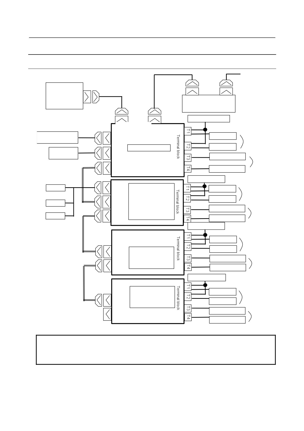
9.11.5.1 Overall connection diagram
CNC
I/O Link
JD51A
JD1B
JD1A
I/O Unit, etc.
Power supply for load
FANUC I/O Link
JD1B
JD1A
24 VDC power supply
Relay, etc.
CP11A
16 DO points
Basic module
Relay, etc.
External device
CP11B
Switch, etc.
24 DI
points
CA105
Inter-module
Switch, etc.
cable A
Power supply for load
JA3
Expansion module A
MPG
Relay, etc.
With MPG
16 DO points
or
Relay, etc
CA106
MPG
Expansion module B, C or
D
Switch, etc.
24 DI
Without MPG
points
CA105
MPG
Switch, etc.
Power supply for load
Relay, etc.
Inter-module cable
16 DO points
A
Relay, etc.
CA106
Expansion module B, C,
or D
Switch, etc.
Without MPG
24 DI
CA105
points
Switch, etc.
Power supply for load
Inter-module
cable A
Expansion module B, C,
Relay, etc.
or D
16 DO points
CA106
Without MPG
Relay, etc.
Switch, etc.
CA105
24 DI
points
Switch, etc.
NOTE
Expansion module C does not have DI points.
With expansion module D, only the terminal blocks for analog input, T1 and T2,
are available.
- 296 -
B-64303EN/03
9.CONNECTION OF I/O Link SLAVE DEVICES
9.11.5.2 Power connection
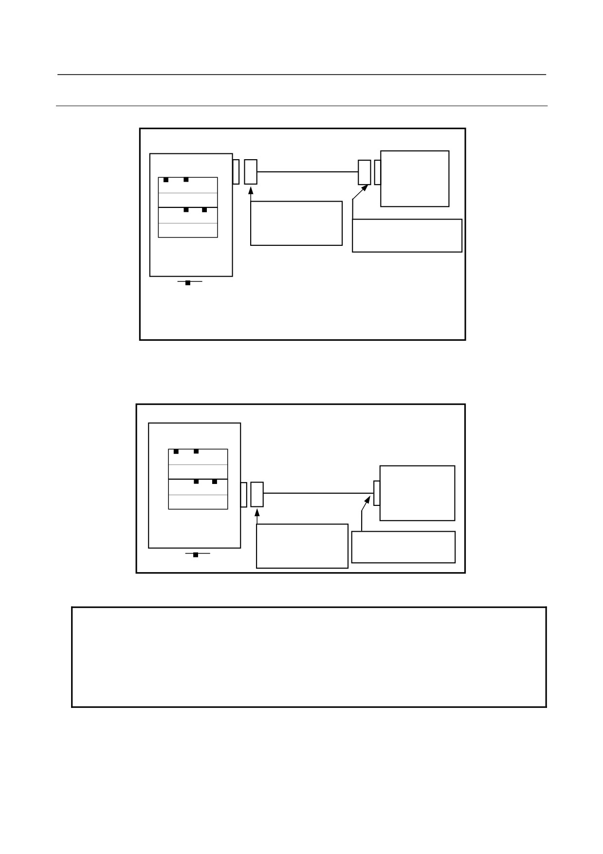
Supply power to the basic module from the CNC or an external 24 VDC regulated power supply.
24 VDC power supply
Basic module
Connected for input
CP11A
For input
Regulated
power supply 24
A3 A2 A1
VDC ±10%
0V
Tyco Electronics AMP
B3 B2 B1
1-178288-3 (housing)
0V
Make a selection matching
1-175218-5 (contact)
the power supply used.
CP11B
For branch output
Key arrangement
Recommended cable (for using external power): A02B-0124-K830
(5 m long, with an M3 terminal on the 24 V power supply side)
The 24 VDC input to CP11A (A1, A2) can be output from CP11B (B1, B2) for branching. CP11B (B1,
B2) is connected as shown below. In this case, the external 24 VDC power supply needs to provide
CP11A (A1, A2) with a current which is equal to the sum of the current consumed by the control unit and
the current used via CP11B (B1, B2).
Basic module
CP11A
For input
A3 A2 A1
External device
0V
Connected for branching
B3 B2 B1
0V
CP11B
For branching
Tyco Electronics AMP
Make a selection matching
2-178288-3 (housing)
the external device.
1-175218-5 (contact)
Key arrangement
The maximum DC output supplied by the CP11B is 2 A.
NOTE
1 Ensure that +24 V is supplied either when or before the power to the CNC is
turned on, and that +24 V is removed either when or after the power to the CNC
is turned off.
2 When turning off the power to the CNC control unit, be sure to turn off the power
to the terminal type I/O module and other slave I/O units connected via the I/O
Link as well.
- 297 -
9.CONNECTION OF I/O Link SLAVE DEVICES
B-64303EN/03
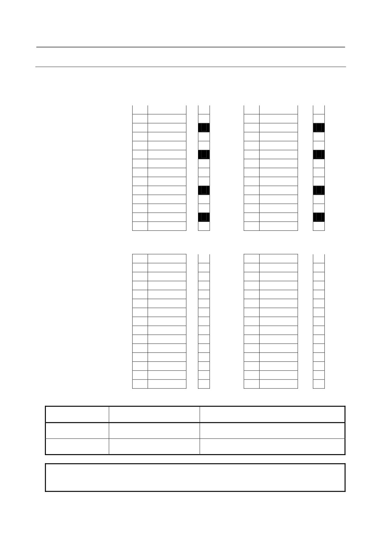
9.11.5.3 Signal assignment on terminal blocks
Basic module, expansion modules A and B
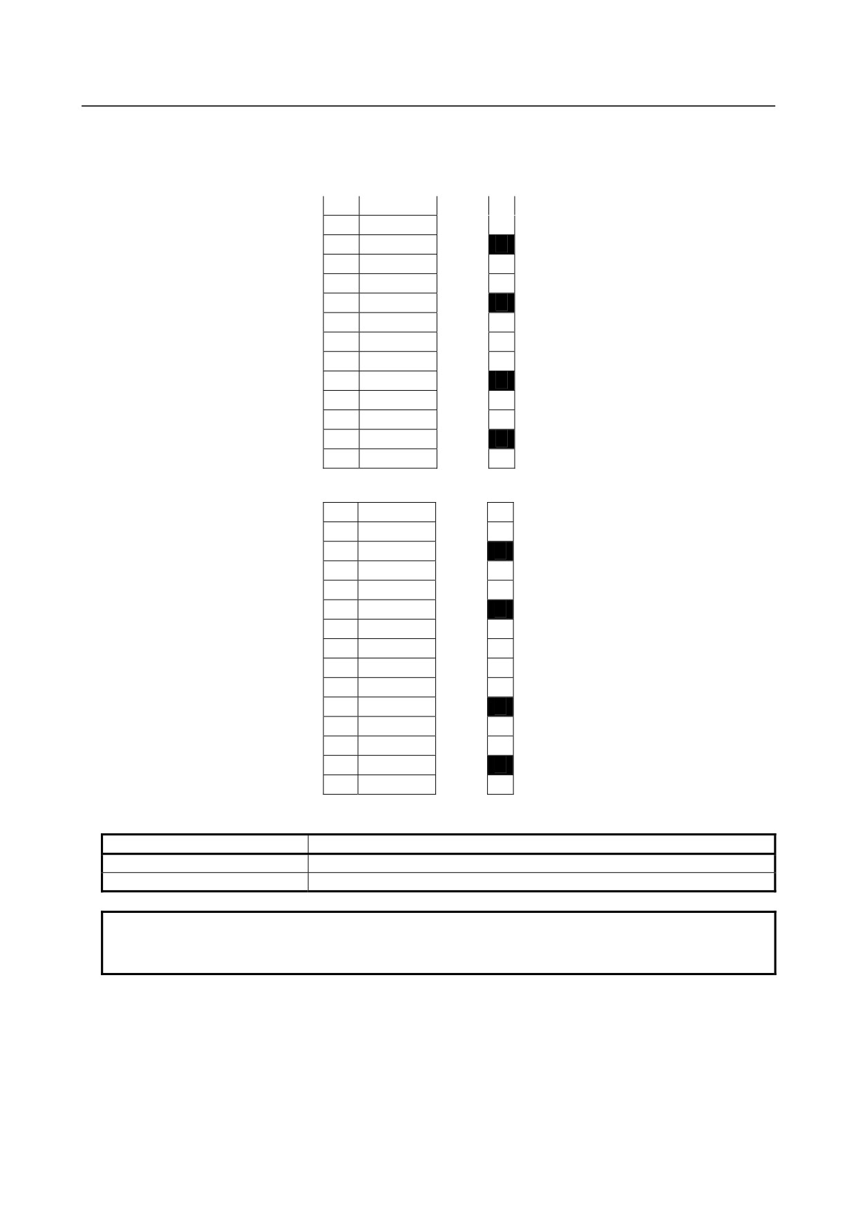
-
Assignment of signals for output
T1 (Label color: Light blue) Label indication T2 (Label color: Yellow green) Label indication
1
DOCOM0
V
1
DOCOM0
V
2
Yn+0.0
0
2
Yn+0.1
1
3
0V-0
G
3
0V-0
G
4
Yn+0.2
2
4
Yn+0.3
3
5
Yn+0.4
4
5
Yn+0.5
5
6
0V-0
G
6
0V-0
G
7
Yn+0.6
6
7
Yn+0.7
7
8
DOCOM1
V
8
DOCOM1
V
9
Yn+1.0
0
9
Yn+1.1
1
10
0V-1
G
10
0V-1
G
11
Yn+1.2
2
11
Yn+1.3
3
12
Yn+1.4
4
12
Yn+1.5
5
13
0V-1
G
13
0V-1
G
14
Yn+1.6
6
14
Yn+1.7
7
-
Assignment of signals for input
T3 (Label color: Yellow)
Label indication
T4 (Label color: Pink)
Label indication
1
DICOM
C
1
DICOM
C
2
Xm+0.0
0
2
Xm+0.1
1
3
Xm+0.2
2
3
Xm+0.3
3
4
Xm+0.4
4
4
Xm+0.5
5
5
Xm+0.6
6
5
Xm+0.7
7
6
DICOM
C
6
DICOM
C
7
Xm+1.0
0
7
Xm+1.1
1
8
Xm+1.2
2
8
Xm+1.3
3
9
Xm+1.4
4
9
Xm+1.5
5
10
Xm+1.6
6
10
Xm+1.7
7
11
DICOM
C
11
DICOM
C
12
Xm+2.0
0
12
Xm+2.1
1
13
Xm+2.2
2
13
Xm+2.3
3
14
Xm+2.4
4
14
Xm+2.5
5
15
Xm+2.6
6
15
Xm+2.7
7
-
Terminal block specification
Terminal block
Terminal block specification
Remarks
name
on cable side
T1
Weidmuller BLZF3.5/14F
Each of terminal blocks T1 and T2 has a different
T2
color assigned by the label attached to the main unit.
T3
Weidmuller BLZF3.5/15F
Each of terminal blocks T3 and T4 has a different
T4
color assigned by the label attached to the main unit.
NOTE
The terminal blocks on the cable side are shipped with the terminal type I/O
module.
- 298 -
B-64303EN/03
9.CONNECTION OF I/O Link SLAVE DEVICES
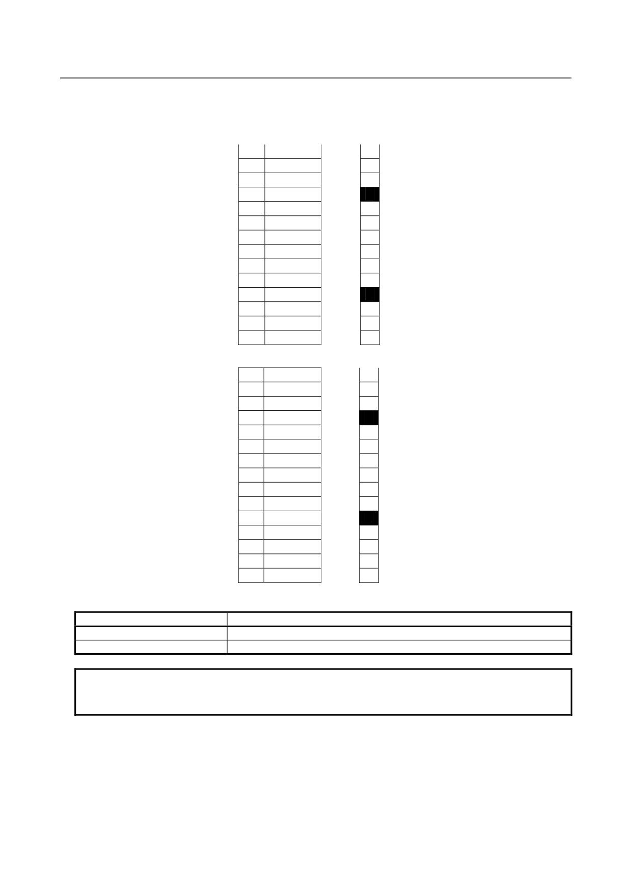
Expansion module C
-
Assignment of signals for output
T1 (Label color: Light blue) Label indication
1
DOCOM0
V
2
Yn+0.0
0
3
0V-0
G
4
Yn+0.1
1
5
Yn+0.2
2
6
0V-0
G
7
Yn+0.3
3
8
DOCOM1
V
9
Yn+0.4
4
10
0V-1
G
11
Yn+0.5
5
12
Yn+0.6
6
13
0V-1
G
14
Yn+0.7
7
T2 (Label color: Yellow green)
Label indication
1
DOCOM2
V
2
Yn+1.0
0
3
0V-2
G
4
Yn+1.1
1
5
Yn+1.2
2
6
0V-2
G
7
Yn+1.3
3
8
9
DOCOM3
V
10
Yn+1.4
4
11
0V-3
G
12
Yn+1.5
5
13
Yn+1.6
6
14
0V-3
G
15
Yn+1.7
7
-
Terminal block specification
Terminal block name
Terminal block specification on cable side
T1
Weidmuller BLZF3.5/14F
T2
Weidmuller BLZF3.5/15F
NOTE
The terminal blocks on the cable side are shipped with the terminal type I/O
module.
- 299 -
9.CONNECTION OF I/O Link SLAVE DEVICES
B-64303EN/03
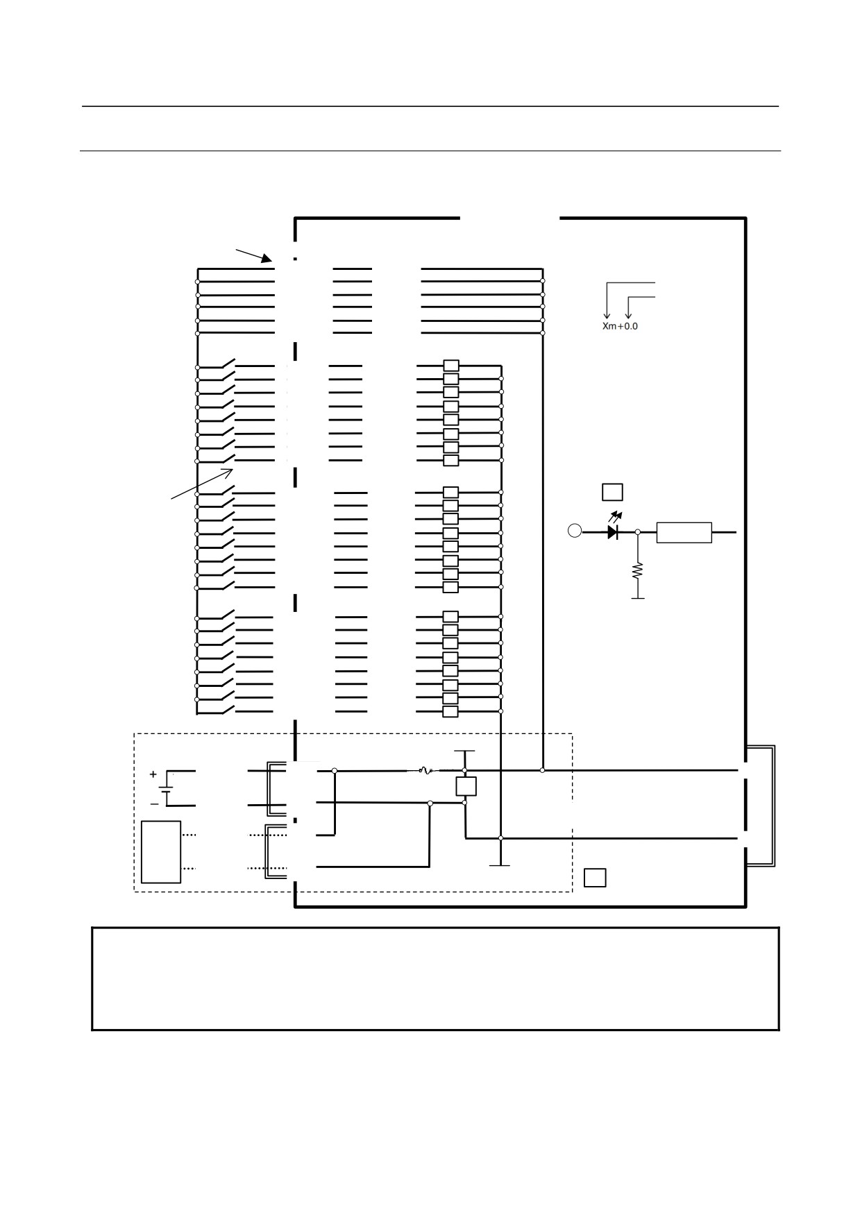
Expansion module D
-
Assignment of signals for analog input
T1 (Label color: Yellow)
Label indication
1
JMP0
J
2
INP0
+
3
INM0
-
4
COM0
C
5
FG0I
F
6
FG0O
F
7
8
JMP1
J
9
INP1
+
10
INM1
-
11
COM1
C
12
FG1I
F
13
FG1O
F
14
T2 (Label color: Pink)
Label indication
1
JMP2
J
2
INP2
+
3
INM2
-
4
COM2
C
5
FG2I
F
6
FG2O
F
7
8
JMP3
J
9
INP3
+
10
INM3
-
11
COM3
C
12
FG3I
F
13
FG3O
F
14
15
-
Terminal block specification
Terminal block name
Terminal block specification on cable side
T1
Weidmuller BLZF3.5/14F
T2
Weidmuller BLZF3.5/15F
NOTE
The terminal blocks on the cable side are shipped with the terminal type I/O
module.
- 300 -
B-64303EN/03
9.CONNECTION OF I/O Link SLAVE DEVICES
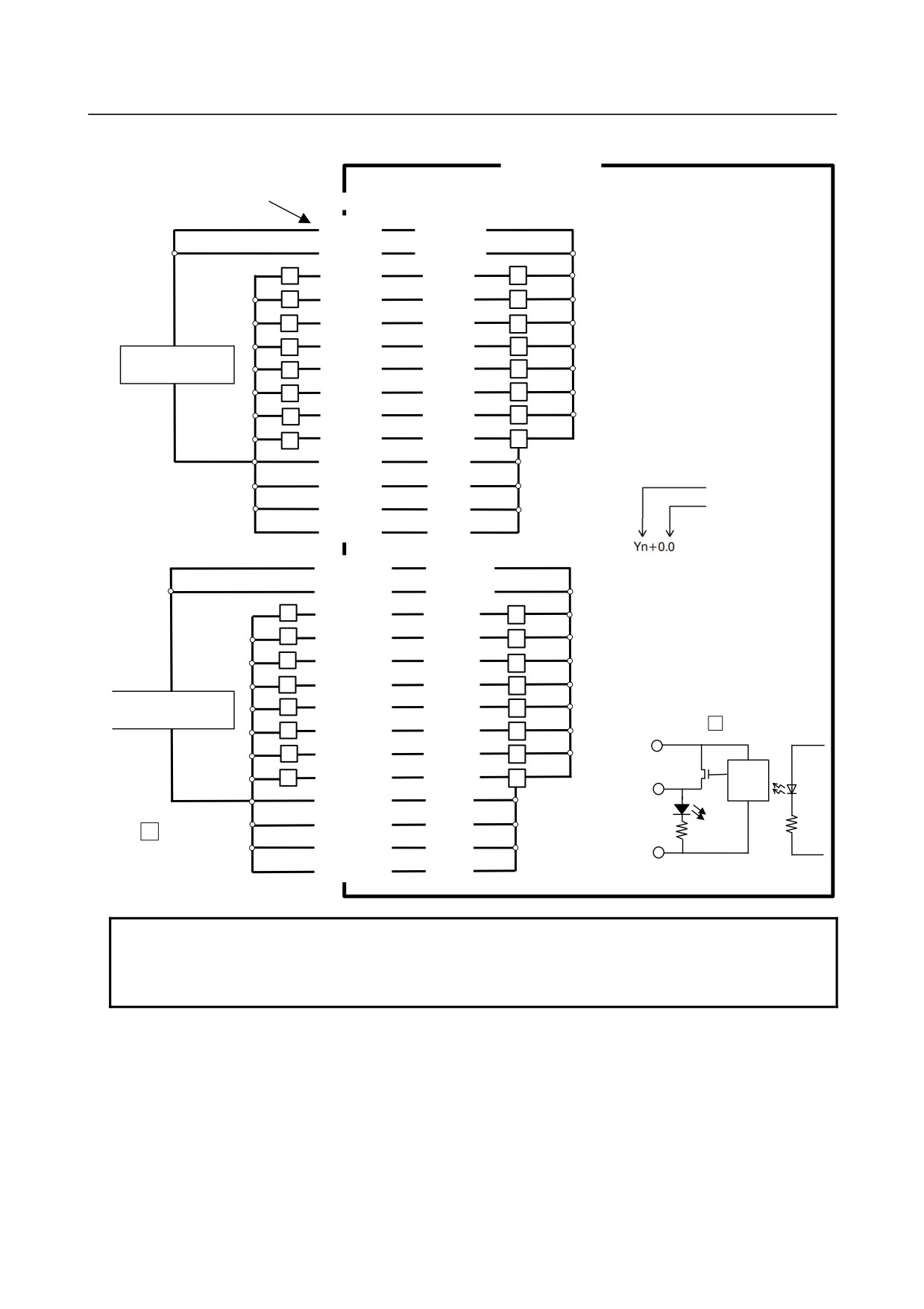
9.11.5.4 DI/DO connection
Basic module, expansion modules A and B
DI connection
Inside module
Indication on terminal
block label
Terminal
Terminal block and pin No.
name
C
○T3-1
DICOM
C
○T3-6
DICOM
Address number
C
○T3-11
DICOM
Bit number
C
○T4-1
DICOM
C
○T4-6
DICOM
C
○T4-11
DICOM
0
○T3-2
Xm+0.0
I
1
○T4-2
Xm+0.1
I
2
○T3-3
Xm+0.2
I
3
○T4-3
Xm+0.3
I
4
○T3-4
Xm+0.4
I
5
○T4-4
Xm+0.5
I
6
○T3-5
Xm+0.6
I
7
Xm+0.7
○T4-5
I
0
I
I
Input circuit
○T3-7
Xm+1.0
1 ○T4-7
I
Switch, etc.
Xm+1.1
LED
2 ○T3-8
I
3 ○T4-8
I
Receiver
Xm+1.2
4 ○T3-9
I
Input pin
5 ○T4-9
Xm+1.3
I
6 ○T3-10
I
7
○T4-10
Xm+1.4
I
0V
0
○T3-12
Xm+2.0
I
1 ○T4-12
I
Xm+2.1
2 ○T3-13
I
3 ○T4-13
Xm+2.2
I
4 ○T3-14
I
5 ○T4-14
Xm+2.3
I
6 ○T3-15
I
7 ○T4-15
Xm+2.4
I
24V
Control power
Fuse
24V
24VIN
○A1
○
CP11
2A
C
EXPANSION
0VIN
○A2
(Connected to expansion module)
Ex-
○B1
24VOUT
ternal
○
CP11
devic
0V
0VOUT
○B2
e
0V
C
: Control circuit
NOTE
The circuitry enclosed in the dashed rectangle shown above is mounted on the
basic module only. In the case of an expansion module, 24 V for DICOM is
supplied via the extension cable from the basic module or the expansion module
at the preceding stage.
- 301 -
9.CONNECTION OF I/O Link SLAVE DEVICES
B-64303EN/03
DO connection
Inside module
Indication on terminal
Terminal
block label
Terminal block and pin No.
name
V
○T1-1
DOCOM0
V
○T2-1
DOCOM0
0 ○T1-2
Yn+0.0
L
O
1 ○T2-2
Yn+0.1
L
O
2 ○T1-4
Yn+0.2
L
O
+
3 ○T2-4
Yn+0.3
L
O
Regulated power
4 ○T1-5
Yn+0.4
supply for load
L
O
5 ○T2-5
Yn+0.5
L
O
-
6 ○T1-7
Yn+0.6
O
L
7
○T2-7
Yn+0.7
L
O
G ○T1-3
0V-0
G ○T2-3
0V-0
Address number
Bit number
G ○T1-6
0V-0
G ○T2-6
0V-0
V ○T1-8
DOCOM1
V ○T2-8
DOCOM1
0
○T1-9
Yn+1.0
O
L
1
○T2-9
Yn+1.1
O
L
2
○T1-11
Yn+1.2
L
O
+
3
○T2-11
Yn+1.3
L
O
Regulated power
4
○T1-12
Yn+1.4
L
O
supply for load
DOCOM0
O : Output circuit
5
○T2-12
Yn+1.5
L
O
or
-
6 ○T1-14
Yn+1.6
L
O
DOCOM1
Internal
7
○T2-14
Yn+1.7
L
O
Output pin
0V-1
circuit
G
○T1-10
LED
0V-1
L
G
○T2-10
: Load
0V-0
0V-1
G
○T1-13
or
G
○T2-13
0V-1
0V-1
NOTE
Be sure to connect the 0 V signal from the regulated power supply for load to the
0 V terminal (with label indication "G") of the module. Otherwise, a load error can
occur.
- 302 -
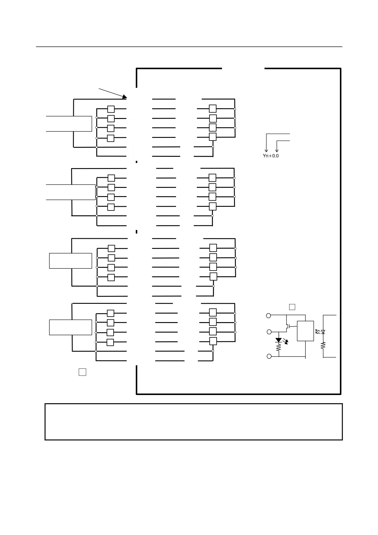
B-64303EN/03
9.CONNECTION OF I/O Link SLAVE DEVICES
Expansion module C
Inside module
Indication on
Terminal
terminal block label
name
V
○T1-1
DOCOM0
0
○T1-2
Yn+0.0
+
L
O
1
○T1-4
Yn+0.1
Regulated power
L
O
supply for load
2
○T1-5
Yn+0.2
L
O
Address number
3
○T1-7
Yn+0.3
-
O
Bit number
L
G
○T1-3
0V-0
G
○T1-6
0V-0
V
○T1-8
DOCOM1
4
○T1-9
Yn+0.4
+
L
O
○T1-11
Yn+0.5
Regulated power
L
5
O
supply for load
○T1-12
Yn+0.6
L
6
O
○T1-14
Yn+0.7
-
7
O
L
G
○T1-10
0V-1
G
○T1-13
0V-1
V ○T2-1
DOCOM2
0
○T2-2
Yn+1.0
+
L
O
Regulated power
1
○T2-4
Yn+1.1
L
O
supply for load
2 ○T2-5
Yn+1.2
O
L
3
○T2-7
Yn+1.3
-
O
L
G ○T2-3
0V-2
G ○T2-6
0V-2
V
○T2-9
DOCOM3
O : Output circuit
4
○T2-10
Yn+1.4
+
L
O
DOCOMn
Regulated power
5
○T2-12
Yn+1.5
O
L
Internal
supply for load
Output pin
6
○T2-13
Yn+1.6
O
L
circuit
7
○T2-15
Yn+1.7
LED
-
O
L
G
○T2-11
0V-3
0V-n
G
○T2-14
0V-3
n: 0 to 3
L
: Load
NOTE
Be sure to connect the 0 V signal from the regulated power supply for load to the
0 V terminal (with label indication "G") of the module. Otherwise, a load error can
occur.
- 303 -
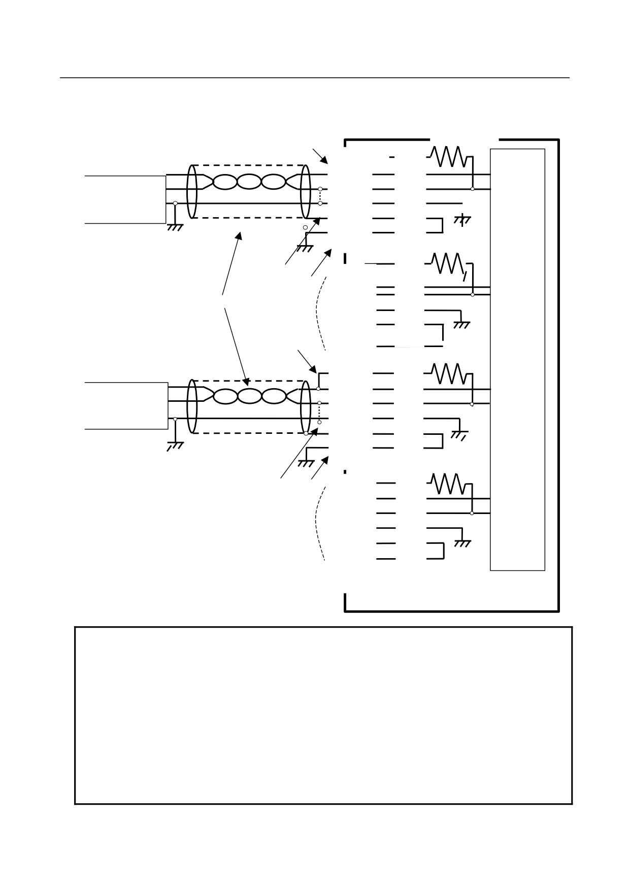
9.CONNECTION OF I/O Link SLAVE DEVICES
B-64303EN/03
Expansion module D
In the example of connection below, CH1 is used for voltage input, CH3 is used for current input, and
CH2 and CH4 are not used.
Label indication
Ins250Ω dule
Terminal
For
voltage
Terminal block No.
CH1
JMP0
i
t
+
○T1-2
INP0
Voltage source +
-
○T1-3
INM0
-
C
○T1-4
COM0
GND
F
○T1-5
FG0I
F
○T1-6
FG0O
250Ω
○T1-7
J
JMP1
NOTE 4
○T1-8
NOTE 3
+
INP1
○T1-9
-
INM1
NOTE 2
○T1-10
CH2
C
COM1
○T1-11
F
FG1I
○T1-12
F
FG1O
NOTE 1
○T1-13
Internal
250Ω
circuit
○T1-14
For current input
CH3
J
○T2-1
JMP2
+
○T2-2
INP2
Current source +
-
○T2-3
INM2
-
C
○T2-4
COM2
GND
F
○T2-5
FG2I
F ○T2-6
FG2O
○T2-7
250Ω
NOTE 4
J
○T2-8
JMP3
NOTE 3
+
○T2-9
INP3
-
○T2-10
INM3
CH4
C
○T2-11
COM3
F
○T2-12
FG3I
F
○T2-13
FG3O
○T2-14
○T2-15
NOTE
1 When JMPn and INPn (n=0, 1, 2, 3) are connected with each other, the channel
becomes a current input channel.
2 For the connection cable, use a shielded twisted pair.
3 In the figure above, the shield is connected to FGnI for grounding to FGnO.
However, the shield may be directly connected to frame ground by using a cable
clamp without using FGnI and FGnO.
4 When a voltage source (current source) has a GND terminal as shown above,
connect COMn to the terminal. When no GND terminal is provided, connect
INMn and COMn with each other on the analog input module as indicated by the
dotted line. COMn of each channel is connected to the common analog ground
inside the module.
- 304 -
B-64303EN/03
9.CONNECTION OF I/O Link SLAVE DEVICES
9.11.5.5 Manual pulse generator connection
Up to three manual pulse generators can be connected to expansion module A. The method of manual
pulse generator connection is the same as for the connector panel I/O module. For details, see Subsection
9.2.15 and Subsection 9.2.16.
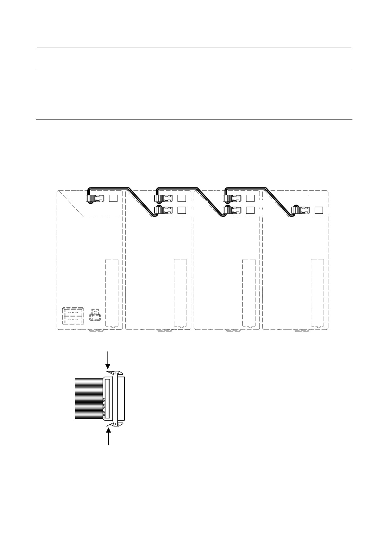
9.11.5.6 Inter-module connection
The same inter-module connection method is applied to between the basic module and an expansion
module and between expansion modules. For inter-module connection, connect a 52-pin flat cable
connector to the expansion connectors CA105 and CA106 provided on each module as shown below. At
this time, connect all 52 pins, paying attention to the connector orientation.
Inter-module
Inter-module
Inter-module
cable A
cable A
cable A
CA105
CA105
CA105
CA106
CA106
CA106
Basic module
Expansion module
Expansion module
Expansion module
A, B, C, or D
B, C, or D
B, C, or D
<Cross sectional view>
Method of detaching a connected cable
When detaching a connected cable from a module, release the lock by
pushing the latch of the connector on the cable side in the arrow directions
shown at the left.
- 305 -
9.CONNECTION OF I/O Link SLAVE DEVICES
B-64303EN/03
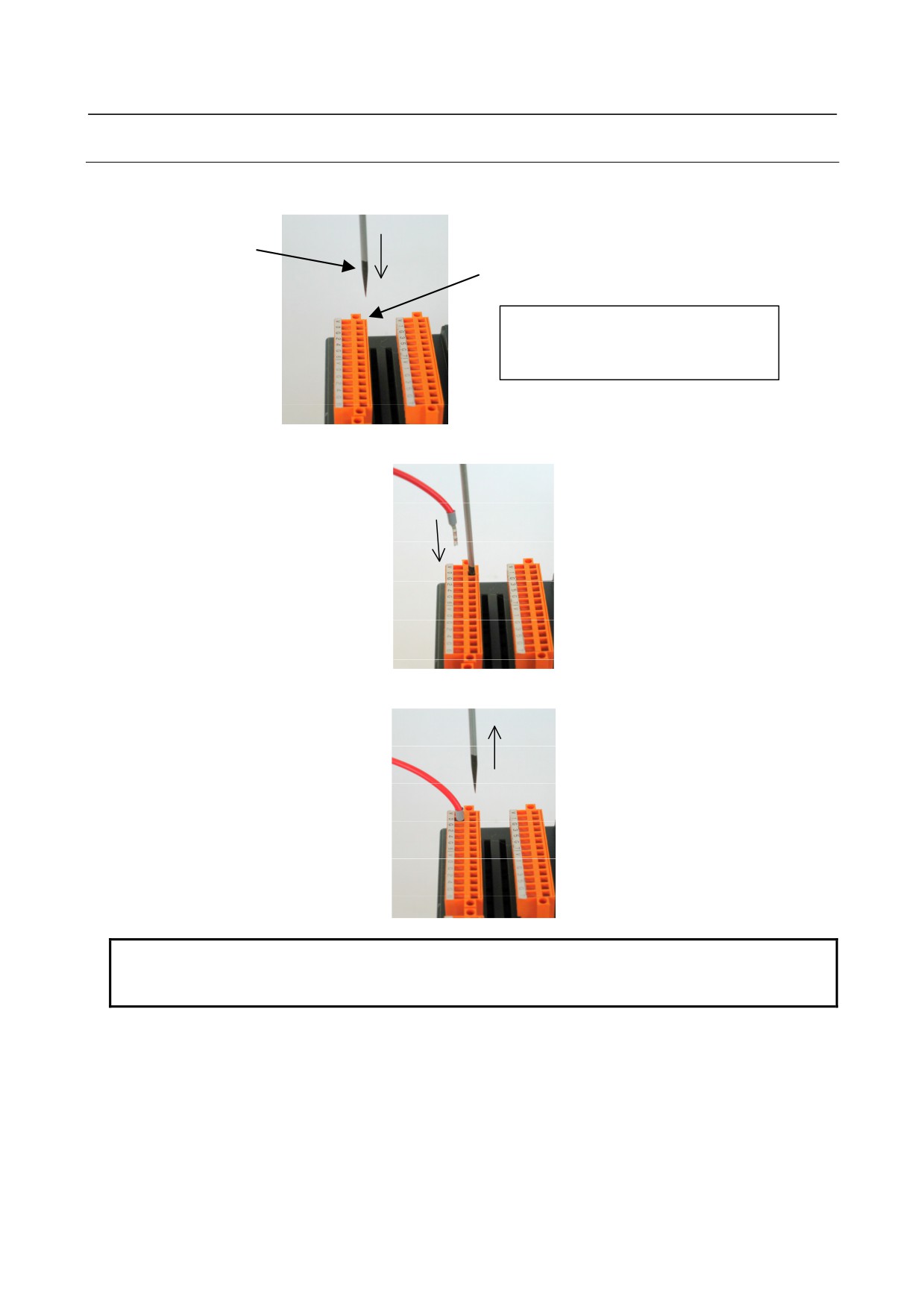
9.11.5.7 Cable connection to a terminal block
(1) Insert a flat-blade screwdriver with a tip width of about 2.5 mm into a clamp of a terminal block to
open the fixing bracket.
Screwdriver
Clamp
Recommended screwdriver
Weidmuller
Product number: SDI 0.4X2.5X80
(2) Insert a cable with a ferrule terminal.
(3) Extract the screwdriver from the clamp to complete cabling.
NOTE
Do not pry the screwdriver in a clamp. Otherwise, the terminal block can be
damaged.
- 306 -
B-64303EN/03
9.CONNECTION OF I/O Link SLAVE DEVICES
9.11.5.8 Detaching a terminal block
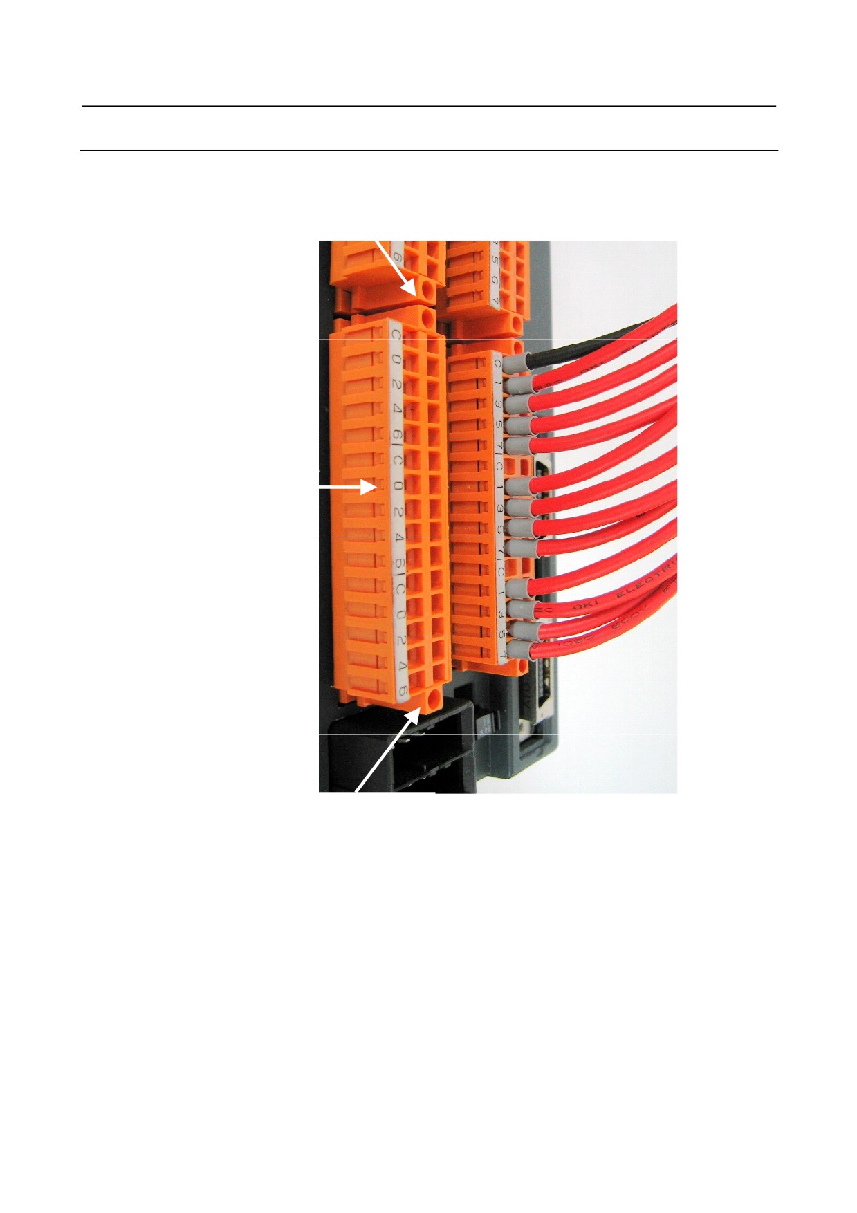
A terminal block can be detached from the main module by loosening the mounting screws at the both
ends of the terminal block.
Mounting screw
Terminal block
Mounting screw
Tightening torque for the mounting screw: 0.4 Nm maximum
- 307 -
9.CONNECTION OF I/O Link SLAVE DEVICES
B-64303EN/03
9.11.6 Settings
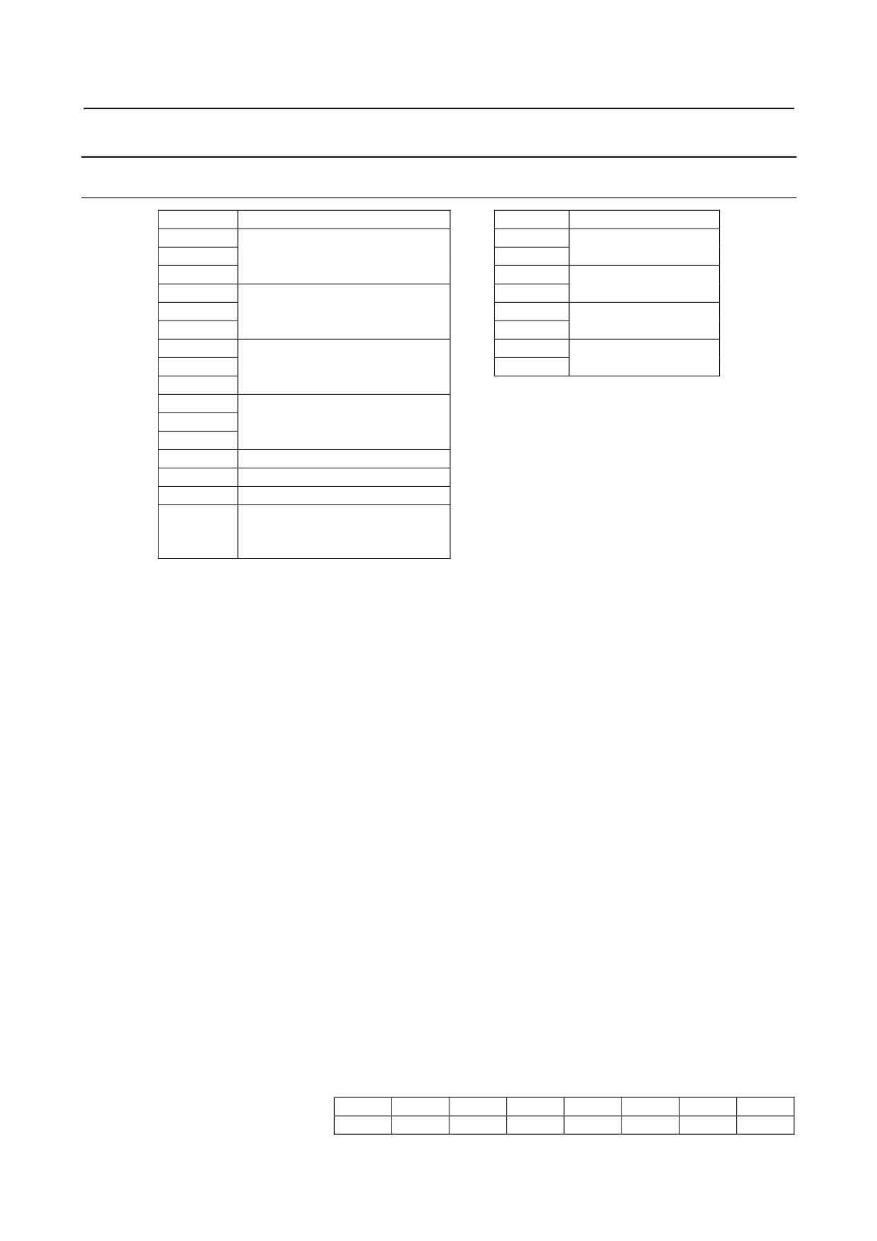
9.11.6.1 Address map
Address
Module, etc.
Address
Module
Xm
Yn
Basic module DO
Xm+1
Basic module DI
Yn+1
Xm+2
Yn+2
Expansion module 1
Xm+3
Yn+3
DO
Xm+4
Expansion module 1 DI
Yn+4
Expansion module 2
Xm+5
Yn+5
DO
Xm+6
Yn+6
Expansion module 3
Xm+7
Expansion module 2 DI
Yn+7
DO
Xm+8
Xm+9
Xm+10
Expansion module 3 DI
Xm+11
Xm+12
1st MPG (Expansion module 1)
Xm+13
2nd MPG (Expansion module 1)
Xm+14
3rd MPG (Expansion module 1)
Xm+15
DO alarm detection
(This address is not used with
expansion module C.)
Basically, the module is allocated a group of DI addresses (16 bytes) and a group of DO addresses (8
bytes). Add or remove up to three expansion modules by hardware as required. The reason is explained
below.
The MPG interface (MPG counter) occupies a DI space from Xm+12 to Xm+14. These addresses are
fixed regardless of whether expansion module 2 or 3 is used, and Xm+12 to Xm+14 must be allocated as
a DI work area to enable the use of the MPG. Therefore, when using an MPG with the i series, allocate DI
addresses in units of 16-byte groups. The CNC directly processes the value of the MPG counter. So,
ensure that the ladder does not use this area.
DI address Xm+15 is used to detect an overheating alarm issued for a cause such as overcurrent of the IC
used for a DO driver. (For details, see Subsection 9.11.6.2, "DO alarm detection".) Address Xm+15 is
fixed regardless of whether expansion module 2 or 3 is used. This address must be allocated as a work
area before this address can be used. When using this area, therefore, allocate DI addresses in units of
16-byte groups.
Addresses of expansion module C
Expansion module C is a module with 16 points for output only but can be allocated in any space of
expansion module 1, 2, or 3. With this module, DO alarm information (2 bytes/module, with DO alarm
information provided for each DO point), which is described later, is allocated to the DI area. For the
relationship between DO bits and DO alarm information, see "Expansion module C" in Subsection
9.11.6.2.
Addresses of expansion module D
<Digital output>
Expansion module D has four analog input channels and has only one 12-bit digital output channel in the
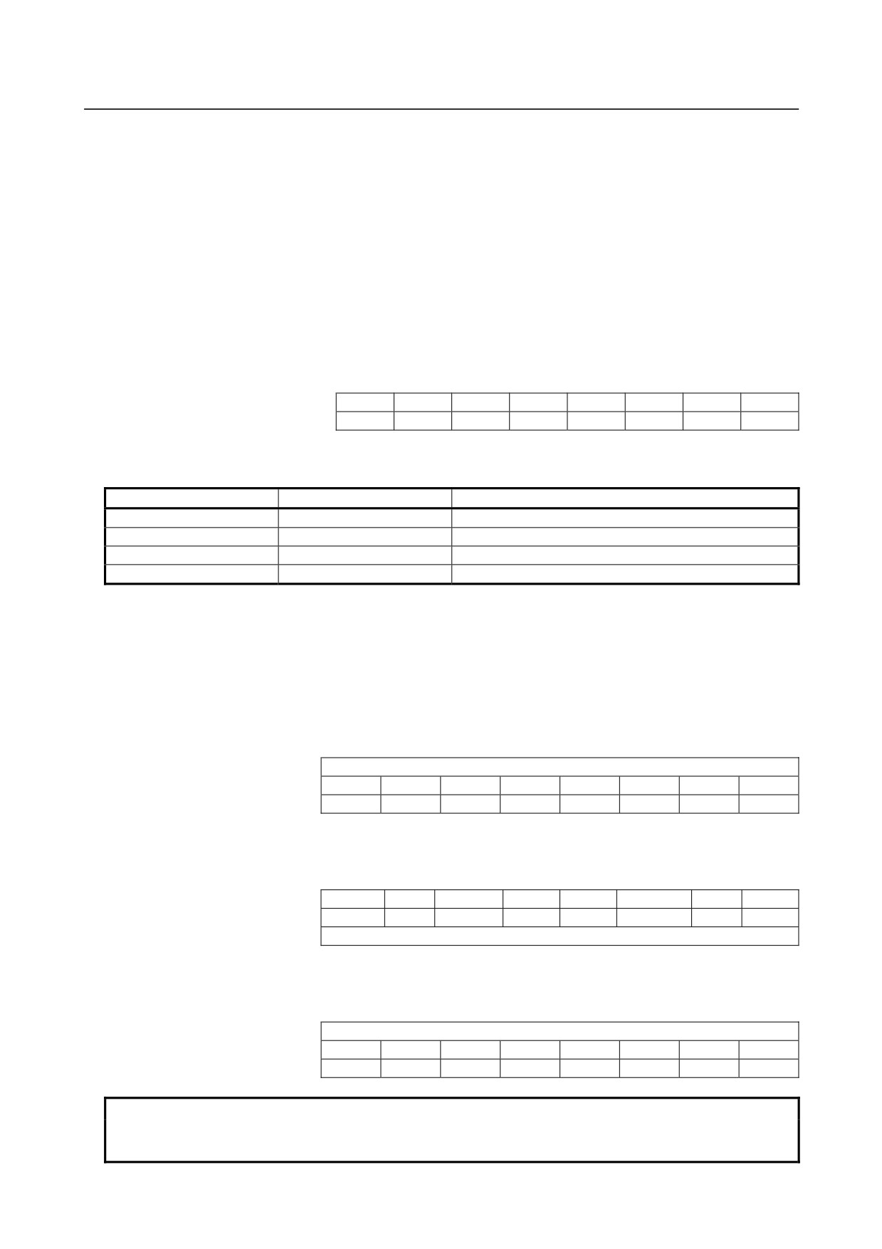
3-byte DI area. The DI format is as indicated below. The digital output addresses start at the first
even-numbered address in the 3-byte area. (See the next page.)
Address in expansion module D
7
6
5
4
3
2
1
0
Xm (even address)
D07
D06
D05
D04
D03
D02
D01
D00
Xm+1 (odd address)
0
0
CHB
CHA
D11
D10
D09
D08
- 308 -
B-64303EN/03
9.CONNECTION OF I/O Link SLAVE DEVICES
D00 to D11 represent 12-bit digital output data (represented as a complement). D00 corresponds to the
weight of 20, and D11 corresponds to the weight of -211. This means that D11 corresponds to the sign bit
of a two's complement.
CHA and CHB select a converted data channel. This means that when the two bytes above are read by a
ladder program, A-D converted data on an input channel selected by CHA and CHB is read as D11 to
D00.
<Channel selection>
When expansion module D is used, which of the four channels is to be output to the DI area of the
module needs to be selected by a ladder program. The channel switching DO points, CHA and CHB, are
mapped to the DO area of the module as indicated below. The symbol × represents an unused bit, and an
unused bit may be set to either 1 or 0.
Address in expansion module D
7
6
5
4
3
2
1
0
Yn
×
×
×
×
×
×
×
×
Yn+1
×
×
×
×
×
×
CHB
CHA
CHA and CHB select a channel as indicated in the table below. The A-D converted data of a selected
channel and the selected channel data are written to the DI area.
CHB
CHA
Channel selected
0
0
Channel 1
0
1
Channel 2
1
0
Channel 3
1
1
Channel 4
<Address>
Be sure to allocate the start address in the DI area of the basic module including expansion module D at
an even-numbered address. When the start address is allocated in this way, the digital output address of
expansion module D is as indicated below, depending on the allocation area.
• When expansion module D is allocated as expansion module 1 (Xm represents an allocation start
address.)
Address in the module
7
6
5
4
3
2
1
0
Xm+3 (odd address)
Undefined
Xm+4 (even address)
D07
D06
D05
D04
D03
D02
D01
D00
Xm+5 (odd address)
0
0
CHB
CHA
D11
D10
D09
D08
• When expansion module D is allocated as expansion module 2 (Xm represents an allocation start
address.)
Address in the module
7
6
5
4
3
2
1
0
Xm+6 (even address)
D07
D06
D05
D04
D03
D02
D01
D00
Xm+7 (odd address)
0
0
CHB
CHA
D11
D10
D09
D08
Xm+8 (even address)
Undefined
• When expansion module D is allocated as expansion module 3 (Xm represents an allocation start
address.)
Address in the module
7
6
5
4
3
2
1
0
Xm+9 (odd address)
Undefined
Xm+10 (even address)
D07
D06
D05
D04
D03
D02
D01
D00
Xm+11 (odd address)
0
0
CHB
CHA
D11
D10
D09
D08
NOTE
When referencing a 2-byte digital output address with a ladder program, be sure
to read from the address in units of 16-bit words.
- 309 -
9.CONNECTION OF I/O Link SLAVE DEVICES
B-64303EN/03
9.11.6.2 DO alarm detection
Basic module, expansion modules A and B
The DO driver has a function for detecting a load overcurrent and its temperature. If an accident such as
the connecting of the cable to ground causes an abnormal increase in the load current or in the DO driver
temperature, a protection circuit, which is provided for each DO driver (1 byte), is activated and keeps the
1-byte DO signal in the OFF state until the cause of the problem is eliminated. Even in this case, the CNC
and I/O module continue operation with no alarm issued. However, the DI address (Xm+15) identifies the
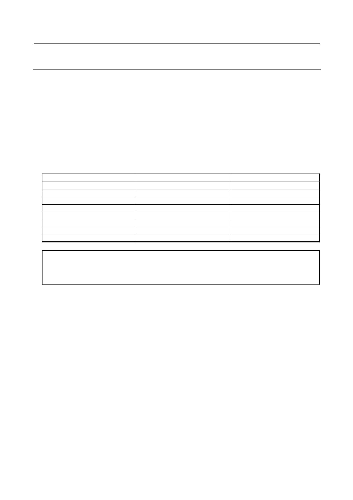
DO driver that has detected the alarm. The table below indicates the correspondence between the DI
address (Xm+15) bits and the DO addresses.
Bit value "1" of the DI address (Xm+15) indicates that the corresponding DO driver has detected an alarm.
If a DO alarm is issued, troubleshooting and recovery can be enhanced by checking the contents of the
Xm+15 area with the DGN screen of the CNC or by performing Xm+15 alarm processing in advance
with the ladder.
Alarm detection address and bit
DO address
Location
Xm+15.0
Yn+0
Basic module
Xm+15.1
Yn+1
Basic module
Xm+15.2
Yn+2
Expansion module 1
Xm+15.3
Yn+3
Expansion module 1
Xm+15.4
Yn+4
Expansion module 2
Xm+15.5
Yn+5
Expansion module 2
Xm+15.6
Yn+6
Expansion module 3
Xm+15.7
Yn+7
Expansion module 3
NOTE
DO alarm information of expansion module C is not written to Xm+15. See the
next item.
Expansion module D does not have this function.
Expansion module C
The DO driver of expansion module C has not only the overheat protection function (overcurrent
detection and temperature detection) as available with the basic module and expansion modules A and B
but also an over voltage protection function and disconnection detection function, and a DO bit is
allocated to each protection circuit.
When any of these functions is activated, the bit corresponding to the LED "ALARM" of the module is
turned on. The CNC continues operation with no alarm issued. However, the DI address area identifies
which DO driver has detected an alarm. The next page indicates the correspondence between the DI
address bits and the DO address bits.
- 310 -
B-64303EN/03
9.CONNECTION OF I/O Link SLAVE DEVICES
DO alarm bit addresses when expansion module C is allocated as expansion modules 1 to 3 (0: No DO
alarm issued, 1: DO alarm issued). *=Don’t care
Bit
Address
7
6
5
4
3
2
1
0
Module
Xm+3
Bit 7 of
Bit 6 of
Bit 5 of
Bit 4 of
Bit 3 of
Bit 2 of
Bit 1 of
Bit 0 of
Yn+2
Yn+2
Yn+2
Yn+2
Yn+2
Yn+2
Yn+2
Yn+2
DO alarm on
Xm+4
Bit 7 of
Bit 6 of
Bit 5 of
Bit 4 of
Bit 3 of
Bit 2 of
Bit 1 of
Bit 0 of
expansion
Yn+3
Yn+3
Yn+3
Yn+3
Yn+3
Yn+3
Yn+3
Yn+3
module 1
Xm+5
Xm+6
Bit 7 of
Bit 6 of
Bit 5 of
Bit 4 of
Bit 3 of
Bit 2 of
Bit 1 of
Bit 0 of
Yn+4
Yn+4
Yn+4
Yn+4
Yn+4
Yn+4
Yn+4
Yn+4
DO alarm on
Xm+7
Bit 7 of
Bit 6 of
Bit 5 of
Bit 4 of
Bit 3 of
Bit 2 of
Bit 1 of
Bit 0 of
expansion
Yn+5
Yn+5
Yn+5
Yn+5
Yn+5
Yn+5
Yn+5
Yn+5
module 2
Xm+8
Xm+9
Bit 7 of
Bit 6 of
Bit 5 of
Bit 4 of
Bit 3 of
Bit 2 of
Bit 1 of
Bit 0 of
Yn+6
Yn+6
Yn+6
Yn+6
Yn+6
Yn+6
Yn+6
Yn+6
DO alarm on
Xm+10
Bit 7 of
Bit 6 of
Bit 5 of
Bit 4 of
Bit 3 of
Bit 2 of
Bit 1 of
Bit 0 of
expansion
Yn+7
Yn+7
Yn+7
Yn+7
Yn+7
Yn+7
Yn+7
Yn+7
module 3
Xm+11
How to view the table above
DO alarm data assigned to bit 5 of address Yn+3 is written to bit 5 of Xm+4.
NOTE
1 DO alarm information on expansion module C is written not to Xm+15 but to the
address indicated above.
2 Xm+5, Xm+8, and Xm+11 cannot be used with expansion module C.
3 Even when expansion module A or B is allocated as expansion module 1 or 2,
address space is not shifted.
The DO driver with the DI address bit set to 1 has detected an alarm. If a DO alarm is issued,
troubleshooting and recovery can be enhanced by checking the contents of the DI area with the DGN
screen of the CNC or by performing DI alarm processing in advance with the ladder.
If a protection function is activated, turn off the DO power and system power then correct the cause that
has activated the protection function.
The table below indicates the DO output state and alarm bit state set when each protection function is
activated.
State when each protection function is activated
DO state
Module DO
DO alarm
DO alarm information
State
PMC output
indication
output
LED (red)
allocated to DI area
LED (green)
Normal operation
0
OFF
Turned off
Turned off
0
1
ON
Turned on
Turned off
0
Overheat protection
0
OFF
Turned off
Turned off
0
function operation
1
OFF
Turned off
Turned on
1
Over voltage protection
0
OFF
Turned off
Turned on
1
function operation
1
OFF
Turned off
Turned off
0
Disconnection
0
OFF
Turned off
Turned off
0
detection
1
ON
Turned on
Turned on
1
- 311 -
9.CONNECTION OF I/O Link SLAVE DEVICES
B-64303EN/03
NOTE
1 If the overheat protection function or over voltage protection function among the
protection functions above is activated, the DO bit is kept OFF until the cause is
eliminated. When the cause is eliminated, the DO bit is set to ON without
restarting the system.
2 Disconnection detection is performed by monitoring, with an output element in
the module, the current flowing through a load when DO output is ON. When the
detected current value is about 100 mA or less, disconnection detection is
assumed. So, when a device (such as an LED) with a small load current is
connected, the DO alarm state results, assuming disconnection detection. Unlike
the other protection functions, however, this function does not turn off DO output.
If a connection is reactivated after the state of disconnection is once set,
disconnection detection is canceled without restarting the system.
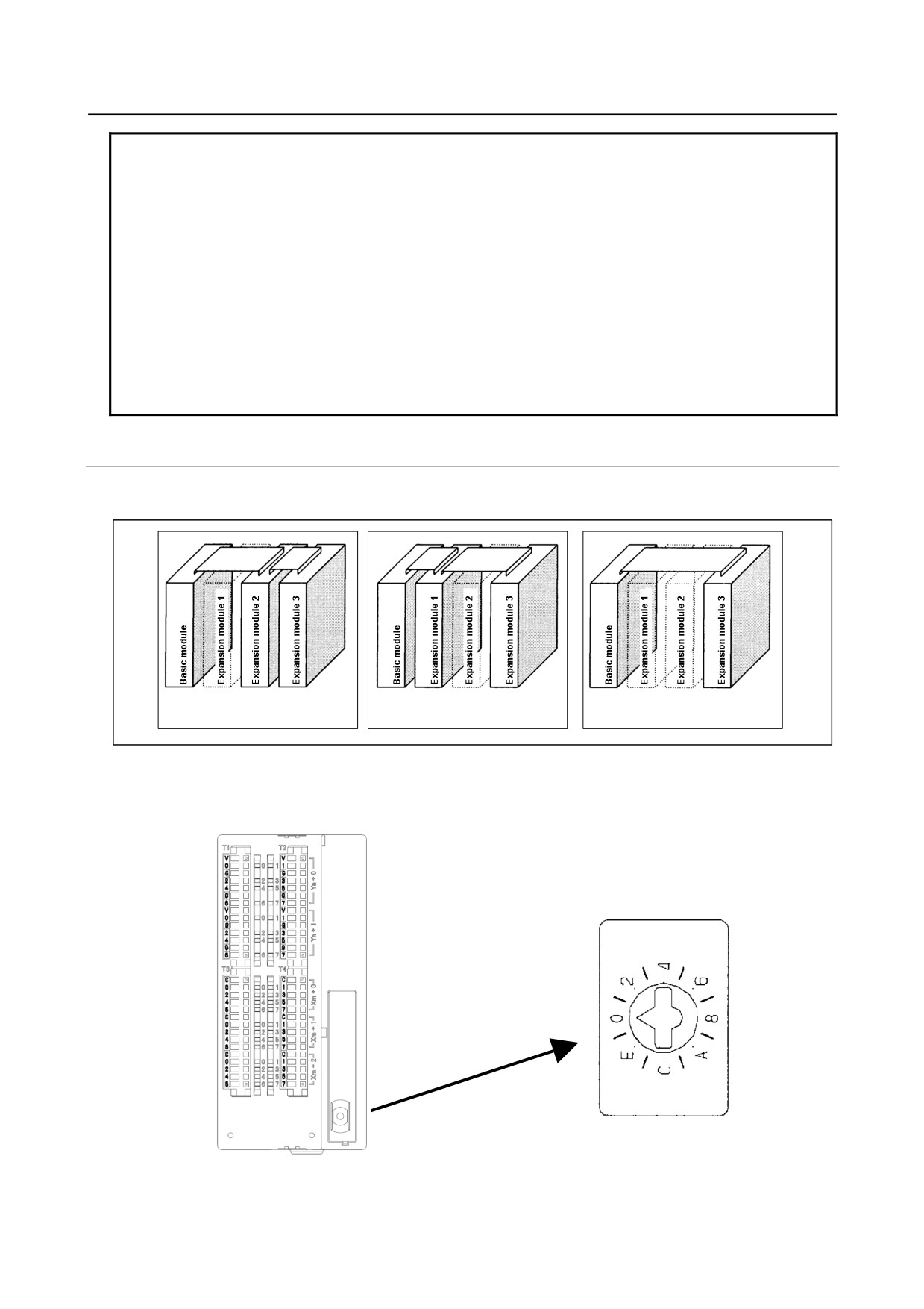
9.11.6.3 Setting the rotary switch
By changing the setting (rotary switch) for the expansion modules, connections can be made by omitting
some expansion modules as shown below.
Expansion module 1 is
Expansion module 2 is
Expansion modules 1 and 2 are
omitted.
omitted.
omitted.
Method of setting (control and method of setting the control)
As shown below, the control (rotary switch) is located on an expansion module. To change the setting,
turn the switch with a flat-bladed screwdriver with a tip width of about 2.5 mm.
Standard setting
- 312 -
B-64303EN/03
9.CONNECTION OF I/O Link SLAVE DEVICES
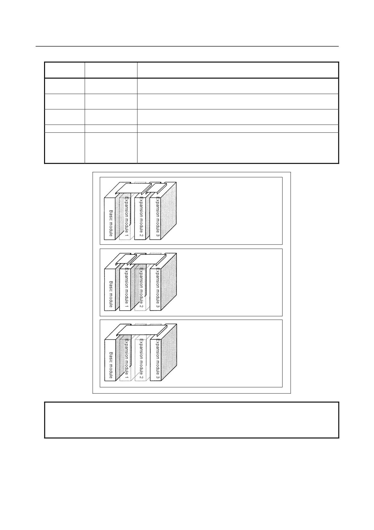
Each setting position of the rotary switch has the following meaning:
Setting
Actual indication
Meaning of setting
position
0
0
This is the standard setting. The rotary switch is factory-set to this position.
This setting is used when no expansion module is omitted.
1
-
Set the rotary switch on an expansion module to this position when the
preceding expansion module is omitted.
2
2
Set the rotary switch on an expansion module to this position when the
preceding two expansion modules are omitted.
3
-
This setting is prohibited.
4~F
4, -, 6, -,
4, 8, or C has the same effect as 0.
8, -, A, -,
5, 9, or D has the same effect as 1.
C, -, E, -,
6, A, or E has the same effect as 2.
7, B, or F has the same effect as 3.
(This setting, however, is prohibited.)
(When expansion module 1 is omitted)
On expansion module 2, set the rotary
switch to setting position 1. On
expansion module 3, keep the rotary
switch set to setting position 0.
(When expansion module 2 is omitted)
On expansion module 3, set the rotary
switch to setting position 1. On
expansion module 1, keep the rotary
switch set to setting position 0.
(When expansion modules 1 and 2 are
omitted)
On expansion module 3, set the rotary
switch to setting position 2.
NOTE
Expansion module A (A03B-0823-C002, with a manual pulse generator
interface) is always mounted at the location of expansion module 1, so that its
setting need not be changed.
- 313 -
9.CONNECTION OF I/O Link SLAVE DEVICES
B-64303EN/03
9.11.7 Others
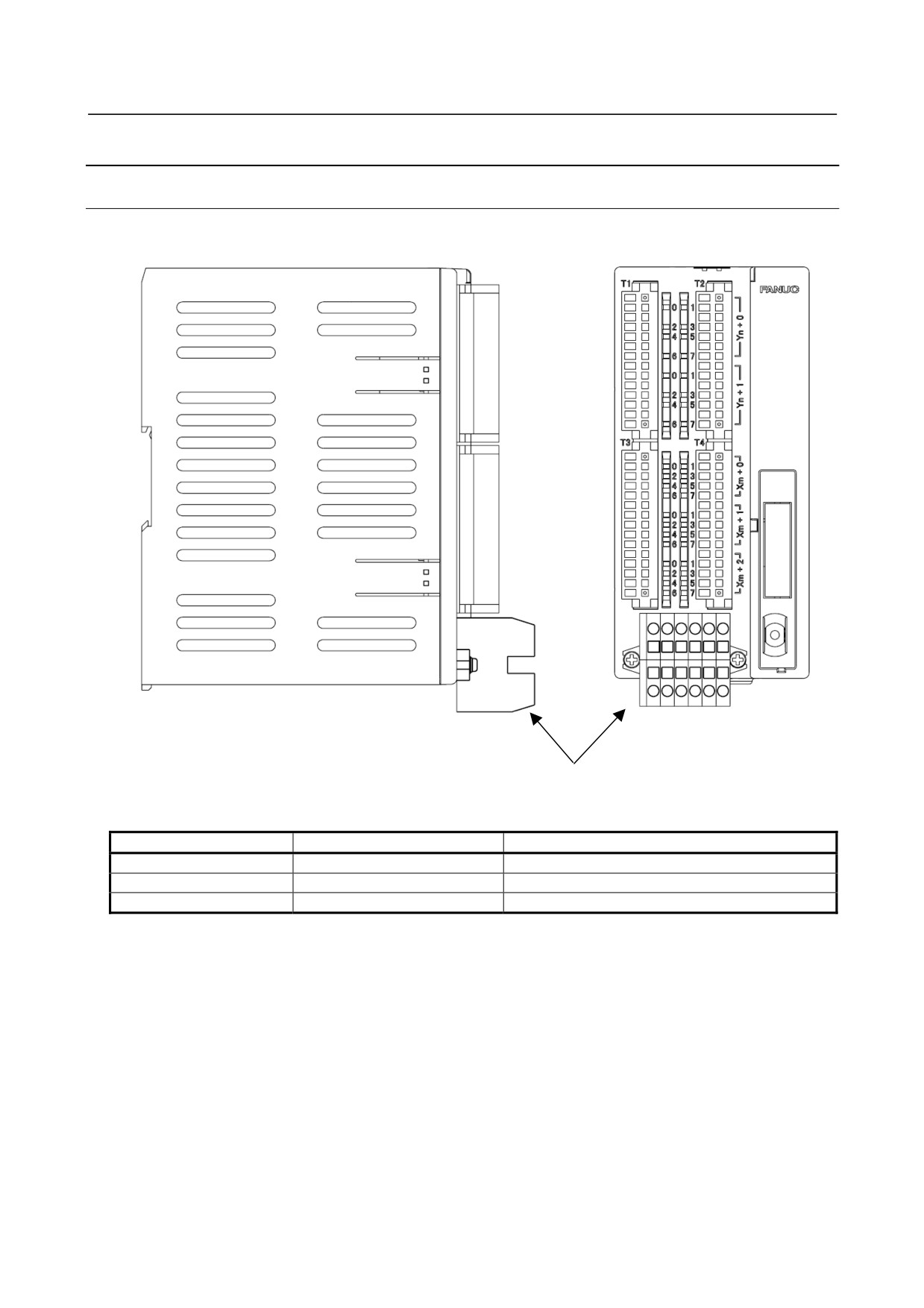
9.11.7.1 Method of common pin expansion
Additional common pins can be provided by mounting (screwing) a commercially available terminal
block on the top cover of an expansion module.
Commercial terminal block
Examples of commercial terminal blocks
Manufacturer
Model
Maximum number of poles
WAGO
869 series
12
Weidmuller
ZDUB2.5 series
10
OSADA
TWM10B series
14
For details of the terminal blocks, contact the respective manufacturers.
- 314 -
B-64303EN/03
9.CONNECTION OF I/O Link SLAVE DEVICES
Mounting dimensions of a commercial terminal block
Unit: mm
NOTE
To fasten a terminal block, use M3 tap screws not longer than 10 mm.
9.11.7.2 DO signal reaction to a system alarm
There is a possibility that the I/O module will not operate normally due to a failure of CNC or I/O Link
slave module, or abnormally power supply voltage. To prevent accidents even in this case, design the
machine to operate safely by making a safety circuit outside the I/O module.
The circuit of this I/O module is designed so that all DO signals are turned off if a system alarm is
occurred in the CNC which controls the I/O module, or if a power of the CNC or the I/O module is turned
off. However, it cannot be guaranteed that DO signals of the I/O module will certainly be turned off.
Therefore, manage signals related to safety by making a safety circuit outside this I/O module.
- 315 -
9.CONNECTION OF I/O Link SLAVE DEVICES
B-64303EN/03
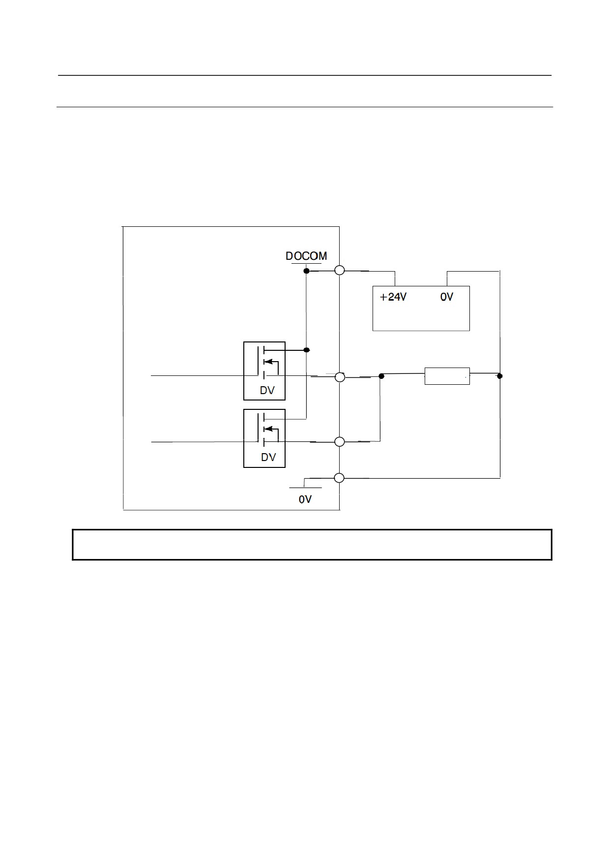
9.11.7.3 Parallel DO (output signal) connection
Basic module, expansion modules A and B
With the basic module and expansion modules A and B, a DO load current two times larger can be
obtained by connecting DO points in parallel and exercising ON/OFF control at the same time in the
sequence as shown below. Namely, the maximum load current per DO point is 200 mA, but 400 mA can
be obtained by connecting two DO points in parallel and turning on the two DO points at the same time.
In this case, however, the leakage current is also doubled up to 40 μA when the DO points are turned off.
Note that the bits that can be set to ON/OFF at the same time must belong to the same address. (For
example, bits at address Yn+3 may be set to ON/OFF at the same time.)
Terminal type I/O module
+24 stabilized power
supply
Load
NOTE
Expansion module C does not allow parallel DO connection.
- 316 -