FANUC Series 16 / 160 / 18 / 180 – Model B. Maintenance Manual - page 17
D. BOOT SYSTEM
APPENDIX
B-62445E/03
The boot system load the CNC system software (flash RAM”DRAM),
D.1
then starts it so that software can be executed.
OVERVIEW
The boot system provides the following maintenance functions for the
CNC:
(1) Registering a file in flash memory
⋅
Reads a file from a memory card, in MS-DOS format conforming
to JEIDA V4.1, into flash memory.
(2) Checking a file (series and edition) in flash memory
(3) Deleting a file from flash memory
(4) Batch saving and restoration of files of parameters and programs
backed up by battery (SRAM area), to and from a memory card
(5) Saving a file in flash memory to a memory card
(6) Formatting of a memory card
(7) Deleting a file from a memory card
This manual describes the activation of the boot system, as well as the
screen displays and operation for the functions listed above.
A kind of memory card
1
We recommend to use SRAM type memory card. When you
use flash type memory card, it is impossible to use functions
(4) to (7).
2
For the 60M1/05 and later versions, data can be saved to
a flash memory card recommended by FANUC. Note,
however, that the actually available memory is equal to the
capacity of the flash memory card, minus 128 KB. The types
of memory cards which can be used are detailed in the
ordering list.
In ordinary system activation, the boot system automatically transfers
D.1.1
files from flash memory to DRAM in the background.
STARTING THE BOOT
The user is not aware of this operation. However, the boot system must
SYSTEM
be operated manually, from menu screen, when maintenance is to be
carried out or when the flash memory does not contain a required file.
1
In system maintenance, for example, to replace a file in memory
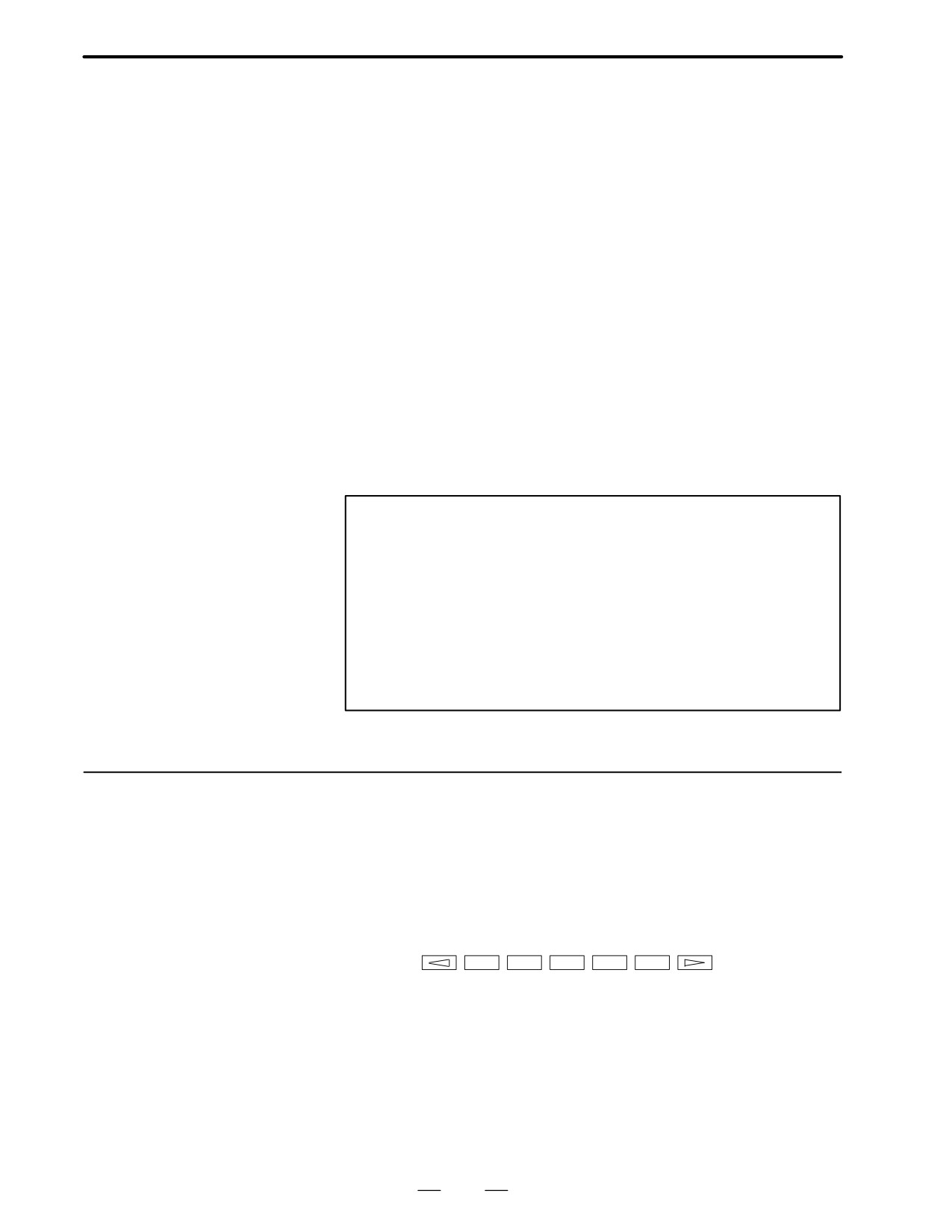
Operation : Turn the power on by simultaneously pressing the two soft
keys at the right end.
ÂÂÂÂ
Hold down the two keys until the boot system screen appears.
2
When the flash memory does not contain a file required to start the
CNC
Immediately after the CNC is turned on, the boot system starts
transferring files from flash memory to DRAM. If, for some reason,
a file required to start the CNC (NC basic) is not in flash memory or
has been destroyed, the boot system is automatically started.
488
B-62445E/03
APPENDIX
D. BOOT SYSTEM
D.1.2
The boot system organizes files in flash memory into two main groups :
system files and user files. These two file types have the following
System Files and User
characteristics :
Files
D System files
CNC and servo control software provided by FANUC
D User files
PMC sequence program (ladder), P-CODE macro program, and other
user-created files
D.1.3
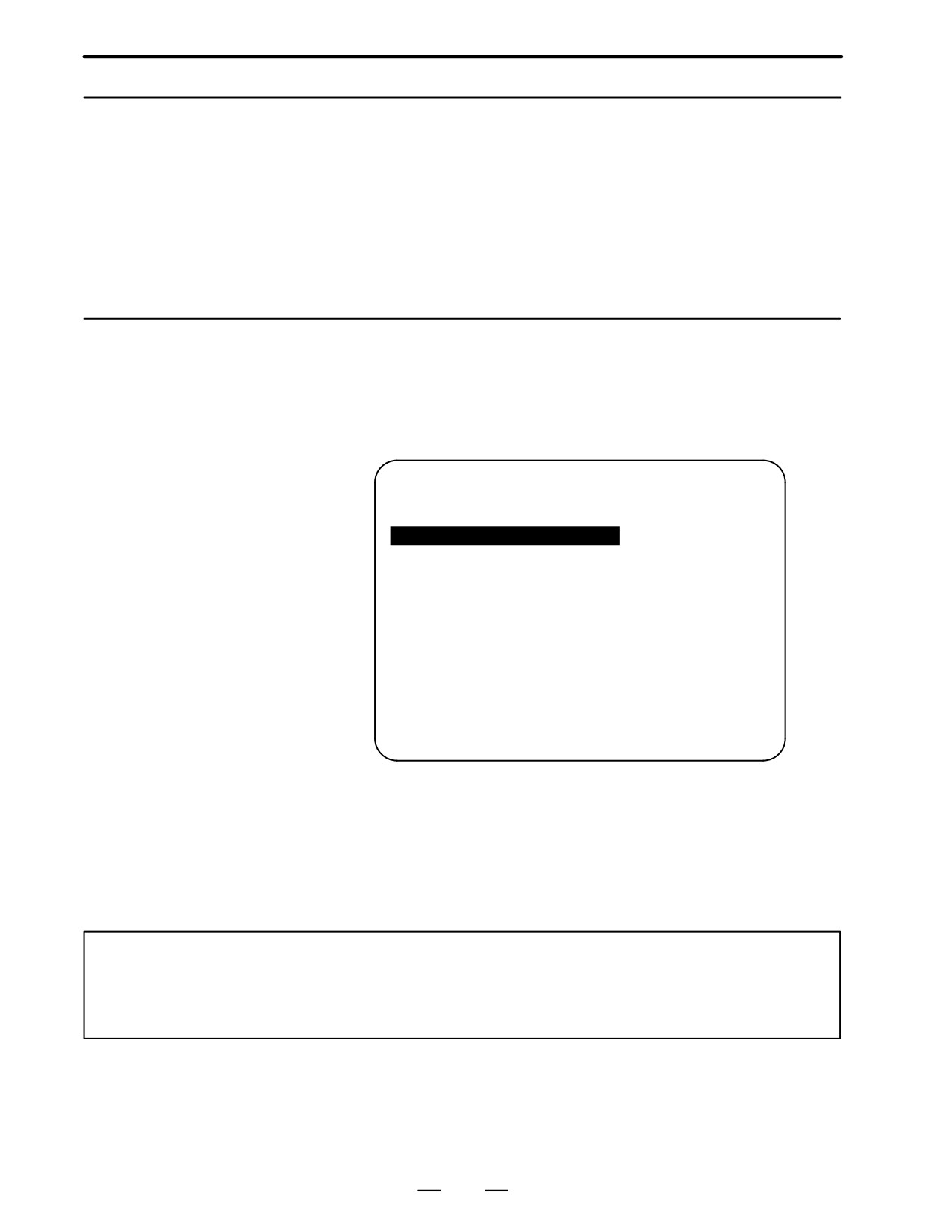
When the CNC includes OPT2 board or LCB, we have to access to flash
memory or SRAM that mounted on additional board. So, the boot system
Boot Slot
displays BOOT SLOT CONFIGURATION screen that to select a access
Configuration Screen
board.
D Screen configuration
(1)
BOOT SLOT CONFIGURATION
60M1-02
(2)
NO. BOARD
F-ROM
SRAM
0.
MAIN
4MB
1.0MB
1. OPT2
6MB
1.0MB
2. OPT3
128KB
3. LCB
512KB
(3)
*** MESSAGE ***
SELECT SLOT AND HIT SELECT KEY.
[ SELECT ][ YES
][ NO
][ UP
][ DOWN
]
1
: Screen title.
2
: Flash memory size and SRAM size of each board.
3
: Message
D Operation
Press the [ UP ] or [DOWN] soft key to move the cursor, and select board
to press the [SELECT] soft key.
Memory card slot
The memory card slot on the loader control board (LCB) is provided specifically for the ladder
edit card for the loader. When a memory card is to be used in the boot system, insert the card
into the slot provided on the main board.
489
D. BOOT SYSTEM
APPENDIX
B-62445E/03
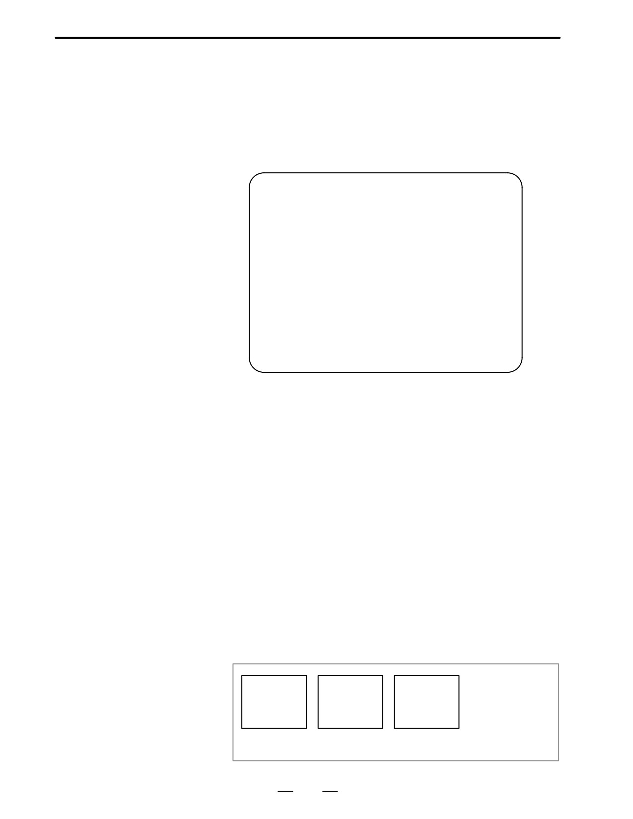
When the boot system is first started, the MAIN MENU screen
is
D.2
displayed. This screen is described below :
SCREEN
CONFIGURATION
AND OPERATING
PROCEDURE
D MAIN MENU screen
(1)
SYSTEM MONITOR MAIN MENU
60M1-01
(2)
1. SYSTEM DATA LOADING
(3)
2. SYSTEM DATA CHECK
(4)
3. SYSTEM DATA DELETE
(5)
4. SYSTEM DATA SAVE
(6)
5. SRAM DATA BACKUP
(7)
6. MEMORY CARD FILE DELETE
(8)
7. MEMORY CARD FORMAT
(9)
9. END
(10
*** MESSAGE ***
)
SELECT MENU AND HIT SELECT KEY.
[ SELECT ][ YES
][ NO
][ UP
][ DOWN
]
1
:
Screen title. The series and edition of the boot system appear at
the right end.
2
:
Function for writing data to flash memory.
3
:
Function for checing the edition of a file in ROM.
4
:
Function for deleting a file from flash memory.
5
:
Function for making a backup copy of the data stored on the memory
card.
6
:
Function for making a backup copy of the data in SRAM.
7
:
Function for deleting a file from a memory card.
8
:
Function for formatting a memory card.
9
:
Function for terminating the boot system and starting the CNC.
10 :
Condensed guidance or error message
D Operating procedure
Press the [UP] or [DOWN] soft key to select the desired function. After
positioning the cursor to the desired function, press the [SELECT] soft
key. Before executing a function, the system my request confirmation
from the operator by having him/her press the [YES] or [NO] soft key.
D Basic operation
Position the
Select a
Check the
cursor.
function
selection
Execute
NUPO
→
NSELECTO
→
NYESO
→ the
→ Select END
NDOWNO
NNOO
function
→ Return to
original state
490
B-62445E/03
APPENDIX
D. BOOT SYSTEM
D.2.1
System Data Loading
Screen
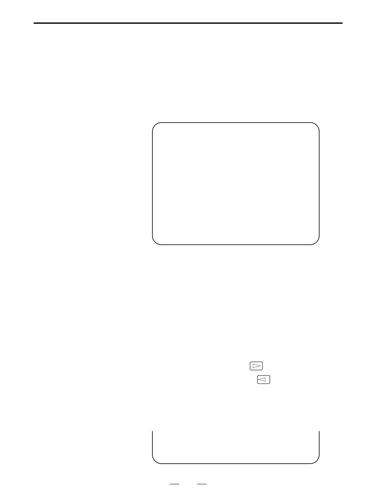
D Description
This screen is used to read a system or user file from a memory card into
flash memory.
D Screen configuration
(1)
SYSTEM DATA LOADING
1/1
(2)
FILE DIRECTORY
D101E10. ROM
D101E11. ROM
(3)
END
(4)
*** MESSAGE ***
SELECT FILE AND HIT SELECT KEY.
[ SELECT ][ YES
][ NO
][ UP
][ DOWN
]
1
: Screen title. The page number (n) and total number of pages (m)
are displayed, in n/m format, at the right end.
2
: Files on the memory card
3
: Option for returning to previous menu Message
4
: Message
D Operating procedure
1
Position the cursor to the file to be read from the memory card and
written to flash memory. Then, press the [SELECT] soft key.
A single page can list up to eight file names. If the memory card
contains nine or more files, the remaining files are displayed on
another page.
To display the next page, press the
soft key.
To display the previous page, press the
soft key. The END option
is displayed on the last page.
The END option is displayed on the last page.
2
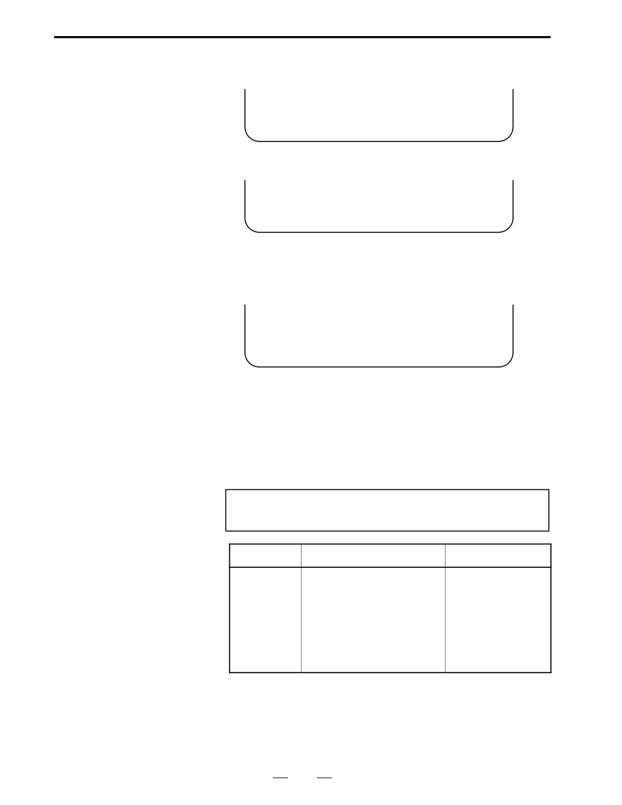
After a file has been slected, the system asks whether that file is to be
loaded.
*** MESSAGE ***
LOADING OK ? HIT YES OR NO.
491
D. BOOT SYSTEM
APPENDIX
B-62445E/03
3
To start loading, press the [YES] soft key. To cancel, press the [NO]
key.
*** MESSAGE ***
LOADING FROM MEMORY CARD.
4
When loading terminates normally, the system displays the following
message. Press the [SELECT] soft key. If an error occurs, see D.3
*** MESSAGE ***
LOADING COMPELETE. HIT SELECT KEY.
D Others
1
Counter display while a file is being loaded
While a file is being loaded, the address of the data currently being
accessed is displayed.
*** MESSAGE ***
LOADING FROM MEMORY CARD.
ADDRESS 001:
² The counter appears under the
message fild.
(1)
1
: Number of 128-KB management unit in flash memory
2
File name in flash memory
The boot systme identifies a file in flash memory by the first four
characters of the file name. If the name of the file to be read from the
memory card and the name of a file already present in flash memory
begin with the same four characters, delete the latter from flash
memory. Then, load the desired file. The following table lists the
names and contents of files.
Note
that these file names may be changed without notice.
File name
Contents
File type
NC BASIC
Basic
System file
DG SERVO
Servo
System file
GRAPHIC
Graphic
System file
NCj OPTN
Optional
System file
PMCj****
PMC control software, etc.
System file
PCD ****
P-CODE macro file/ OMM
User file
CEX ****
C-language executor
User file
PMC - ****
Ladder software
User file
PMC@****
Ladder software for the loader
User file
V : A numeric character, *: An alphabetic character
D.2.2
System Data Check
Screen
492
B-62445E/03
APPENDIX
D. BOOT SYSTEM
D Description
This screen is used to list files in flash memory, together with the
corresponding numbers of 128-KB management units in each file and the
series and edition of the software.
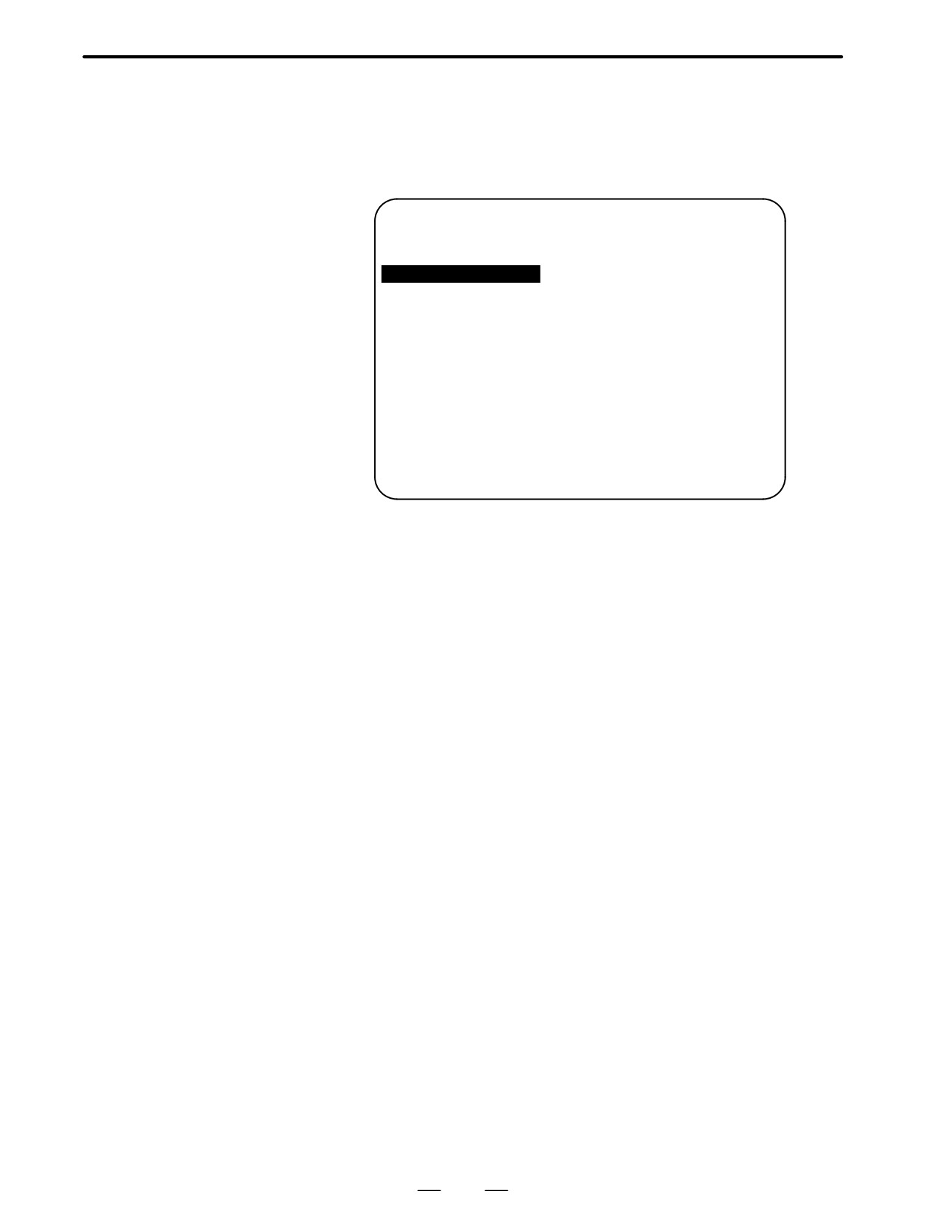
D Screen configuration
(1)
SYSTEM DATA CHECK
1/1
(2)
[BOARD:MAIN]
FILE DIRECTORY (FLASH ROM : 4MB)
(3)
1 NC BASIC
( 8)
2 DG SERVO
( 1)
3 PMC0BSC
( 2)
4 PMC-RB
( 1)
5 PCD 0.5M
( 4)
(4)
END
(5)
*** MESSAGE ***
SELECT FILE AND HIT SELECT KEY.
[ SELECT ][ YES
][ NO
][ UP
][ DOWN
]
1
: Screen title
2
: Names of accessing board
3
: Names of files in flash memory The number of management units
constituting each file appears in parentheses to the right of the file
name.
4
: Returning to the previous menu
5
: Message
493
D. BOOT SYSTEM
APPENDIX
B-62445E/03
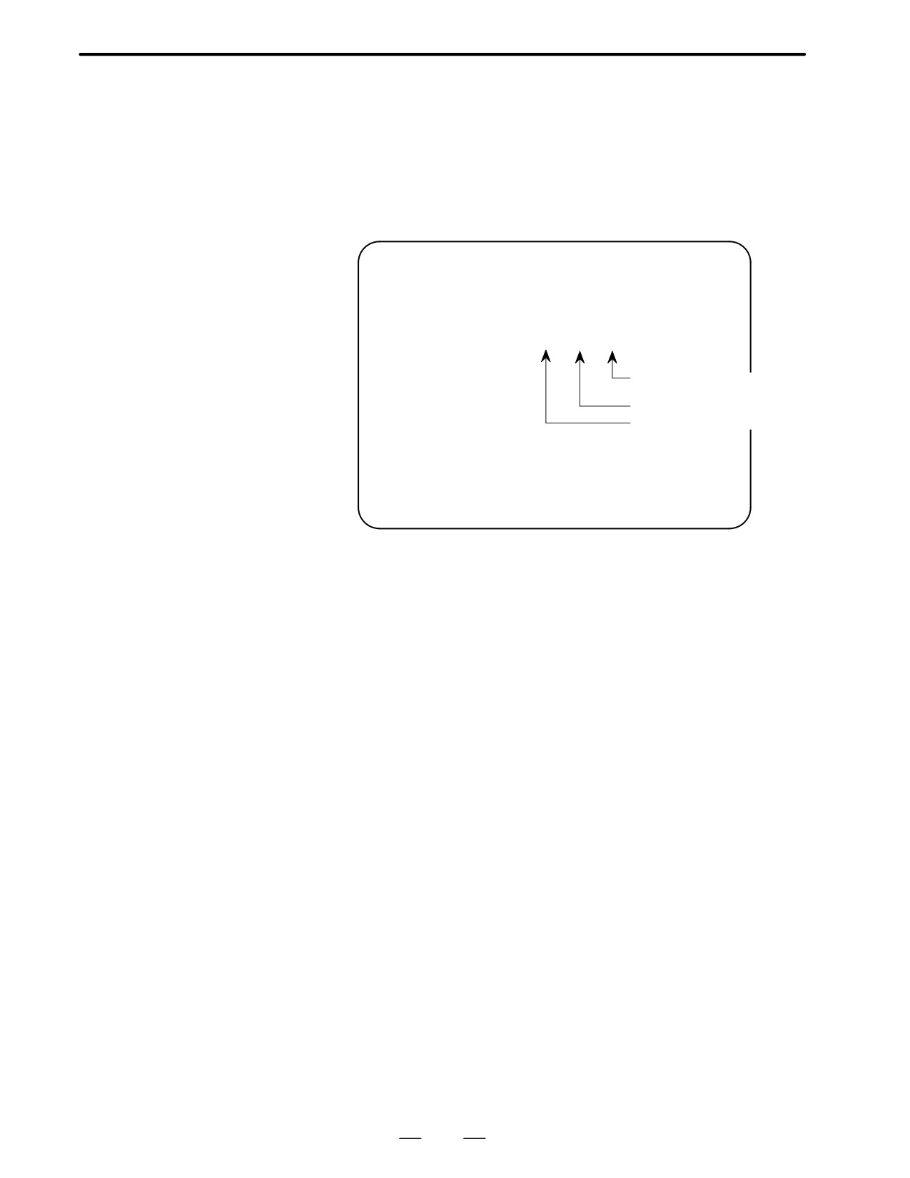
D Operating procedure
1
Select the file whose details are required. For example, select ”1 NC
BASIC (8).”
2
The numbers of management units in the selected file are listed,
together with the series and edition of the software in each
management unit. After checking the listed data, select the
[SELECT] soft key to return to the file selection screen.
ROM FILE CHECK
NC BASIC
0 B1A1 801B 000
1 B1A1 802B 001
0 B1A1 801B 000
2 B1A1 841B 002
3 B1A1 842B 003
4 B1A1 881B 004
ÁInternal management-unitÁ
5 B1A1 882B 005
ÁnumberÁÁÁÁÁÁ
6 B1A1 8C1B 006
ROM number and edition
7 B1A1 8C2B 007
ÁSriesÁÁÁÁÁÁÁ
ÁÁÁÁÁÁÁÁÁ
*** MESSAGE ***
HIT SELECT KEY.
D Others
Parity information for the system file and user file
The NC BASIC, DG SERVO, and other system files in flash memory
contain parity information in each management unit. If the file name field
or parity field on the check screen contains a non-ASC II character or an
”@” , the flash ROM may have been destroyed or a damaged file may
have been read. Re-read the data from the memory card.
The PMC-RB, PCD 0.5M, and other user files do not contain parity
information in each management unit. A non-ASCII character or an ”@”
may appear in the series/edition information. In this case, it does not
indicate that the file has been damaged.
494
B-62445E/03
APPENDIX
D. BOOT SYSTEM
D.2.3
System Data Delete
Screen
D Description
This screen is used to delete a user file from flash memory.
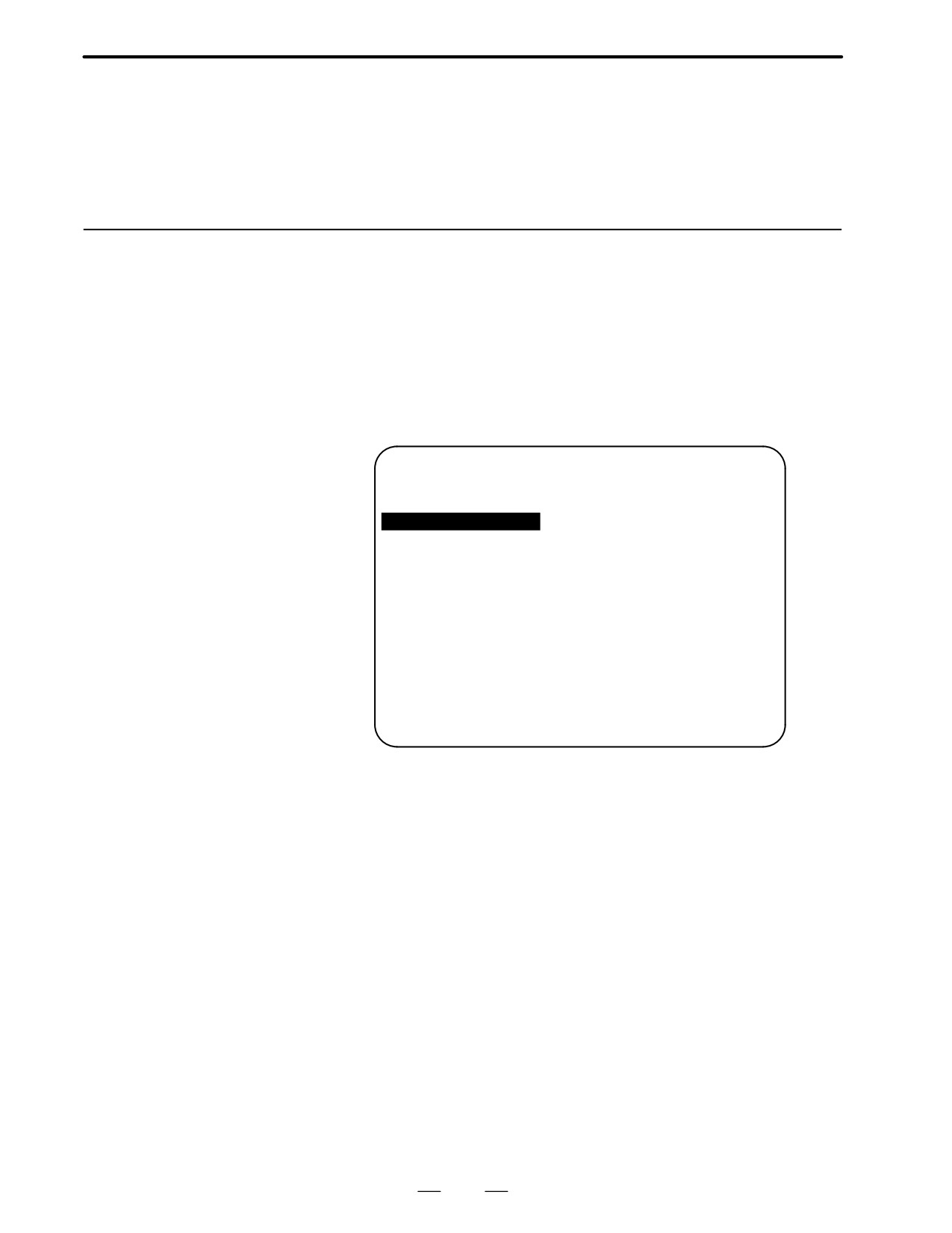
D Screen configuration
(1)
SYSTEM DATA CHECK
1/1
(2)
[BOARD:MAIN]
FILE DIRECTORY (FLASH ROM : 4MB)
(3)
1 NC BASIC
( 8)
2 DG SERVO
( 1)
3 PMC0BSC
( 2)
4 PMC-RB
( 1)
5 PCD 0.5M
( 4)
(4)
END
(5)
*** MESSAGE ***
SELECT FILE AND HIT SELECT KEY.
[ SELECT ][ YES
][ NO
][ UP
][ DOWN
]
1
: Screen title
2
: Names of accessing board
3
: Names of files in flash memory The number of management units
constituting each file appears in parentheses to the right of the file
name.
4
: Returning to the previous menu
5
: Message
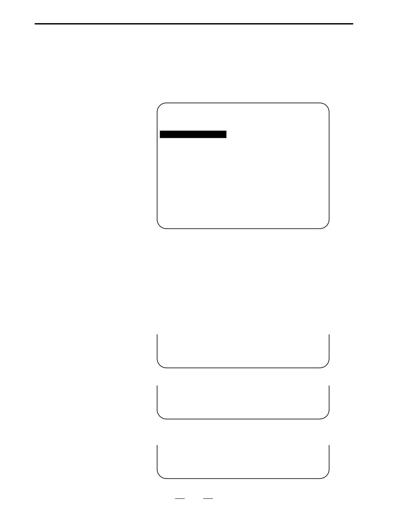
D Operating procedure
1
Position the cursor to the name of the file to be deleted. Press the
[SELECT] soft key.
2
The system displays the following confirmation message :
*** MESSAGE ***
DELETE OK ? HIT YES OR NO.
3
To start the deletion, press the [YES] key. To cancel, press [NO].
*** MESSAGE ***
DELETING ROM FILE IN FLASH MEMORY.
4
When deletion terminates normally, the system displays the following
message. Press the [SELECT] key.
*** MESSAGE ***
DELETING COMPLETE. HIT SELECT KEY.
495
D. BOOT SYSTEM
APPENDIX
B-62445E/03
D Others
1
System files and user files on SYSTEM DATA DELETE screen The
SYSTEM DATA DELETE screen guards against system files being
accidentally deleted by the operator. User files, however, are not
protected. Protected system files can be overwritten from the
SYSTEM DATA LOADING screen.
D.2.4
SYSTEM DATA SAVE
Screen
D Description
This screen is used to write a user file in flash memory to a memory card.
Only user files can be saved from flash memory to a memory card.
System files cannot be saved.
D Screen configuration
(1)
SYSTEM DATA SAVE
(2)
[BOARD:MAIN]
FILE DIRECTORY (FLASH ROM : 4MB)
(3)
1 NC BASIC
( 8)
2 DG SERVO
( 1)
3 PMC0BSC
( 2)
4 PMC-RB
( 1)
5 PCD 0.5M
( 4)
(4)
END
(5)
*** MESSAGE ***
SELECT FILE AND HIT SELECT KEY.
[ SELECT ][ YES
][ NO
][ UP
][ DOWN
]
1
: Screen title
2
: Names of accessing board
3
: Names of files in flash memory The number of management units
constituting each file appears in parentheses to the right of the file
name.
4
: Returning to the previous menu
5
: Message
496
B-62445E/03
APPENDIX
D. BOOT SYSTEM
D Operating procedure
1
Position the cursor to the name of the file to be deleted. Press the
[SELECT] soft key.
2
The system displays the following confirmation message :
*** MESSAGE ***
SAVE OK ? HIT YES OR NO.
3
To start saving, press the [YES] key. To cancel, press [NO].
*** MESSAGE ***
WRITING FLASH ROM FILE TO MEMORY CARD.
SAVE FILE NAME : PMC_RB.000
4
When saving terminates normally, the system displays the
following message. Press the [SELECT] key. The names of files
written to the memory card are listed. Check the file names by, for
example, making a note of the list.
*** MESSAGE ***
FILE SAVE COMPELETE. HIT SELECT KEY.
SAVE FILE NAME : PMC_RB.000
D Others
1
System files and user files on SYSTEM DATA SAVE screen
The SYSTEM DATA SAVE function provides a safeguard against free
copying of the system files.
User files, however, are not protected.
2
Names of saved files
Files saved from flash memory to a memory card have the following
names :
Flash memory
Memory card
PMC-RA
³
PMC_RA. XXX
PMC-RB
³
PMC_RB. XXX
PMC 0.5M
³
PCD_0.5M.XXX
PMC 1.0M
³
PCD_10M.XXX
PMC 1.5M
³
PCD_15M.XXX
CEX1.0M
³
CEX_10M.XXX
CEX 2.0M
³
CEX_20M.XXX
XXX corresponds to the file extension of MS-DOS format files. A
number from 000 to 031 is specified for XXX. For example, if the
PMC-RA file in flash memory is saved to a memory card that does not
yet contain any PMC-RA. * files, the saved file is named PMC-RA.000.
If, however, that file is saved to a memory card that already contains a file
named PMC-RA.000, the saved file is named PMC-RA.001. As files are
added, the extension is incremented up to a maximum of PMC-RA.031.
Any no-longer used numbers in the sequence of the extension numbers
are used in as cending order. If two or more files having identical names
but different extension numbers are normally saved to the memory card,
check the file names displayed subsequently.
497
D. BOOT SYSTEM
APPENDIX
B-62445E/03
D.2.5
SRAM DATA BACKUP
Screen
D Description
This screen is used to collectively save and restore parameters, programs,
and other data, retained after the CNC power is turned off, to and from a
memory card.
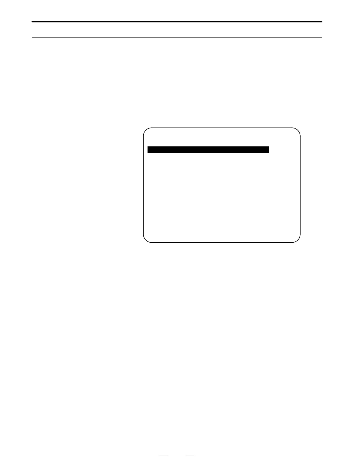
D Screen configuration
Select ”4 SRAM DATA BACKUP” on the SYSTEM MONITOR MAIN
MENU screen. The following screen is displayed.
(1)
SRAM DATA BACKUP
(2)
[BOARD:MAIN]
(3)
1. SRAM BACKUP (CNC
³ MEMORY CARD)
2. RESTORE SRAM (MEMORY CARD
³ CNC)
(4)
END
(5)
SRAM SIZE
:
0.5MB (BASIC)
(6)
FILE NAME
:
SRAM0_5A. FDB
(7)
*** MESSAGE ***
SELECT MENU AND HIT SELECT KEY.
[ SELECT ][ YES
][ NO
][ UP
][ DOWN
]
1
: Screen title
2
: Names of accessing board
3
: Menu
4
: Returning to the previous menu
5
: Size of SRAM mounted on the CNC
6
: File name
7
: Message
498
B-62445E/03
APPENDIX
D. BOOT SYSTEM
D Operating procedure
[Backing up data]
1
Select ”1. SRAM BACKUP.” The following confirmation message is
displayed. Press [YES] to start backup.
*** MESSAGE ***
BACKUP SRAM DATA OK ? HIT YES OR NO.
2
The name of the file being written to the memory card is displayed in
the FILE NAME: field.
SRAM SIZE
: 128K (BASIC)
FILE NAME
: SRAM128K. 000
³ MEMORY CARD
Name of the file being
*** MESSAGE ***
saved
SRAM DATA WRITING TO MEMORY CARD.
3
Upon terminating normally, the system displays the following
message. Press the [SELECT] soft key.
*** MESSAGE ***
SRAM BACKUP COMPLETE. HIT SELECT KEY.
[Restoring the data]
1
Select “2. RESTORE SRAM.” The system displays the following
message. Press the [YES] key.
*** MESSAGE ***
RESTORE SRAM DATA OK ? HIT YES OR NO.
2
The system displays the following message during restoration.
*** MESSAGE ***
RESTORE SRAM DATA FROM MEMORY CARD.
3
Upon terminating normally, the system displays the following
message. Press the [SELECT] soft key.
*** MESSAGE ***
RESTORE COMPLETE. HIT SELECT KEY.
499
D. BOOT SYSTEM
APPENDIX
B-62445E/03
D Others
1
Name of backup file
The name of the backup file written to the memory card by the SRAM
backup function depends on the size of the SRAM installed in the
CNC.
When the size of SRAM is 1MB or larger, backup files are created in
units of 512 KB.
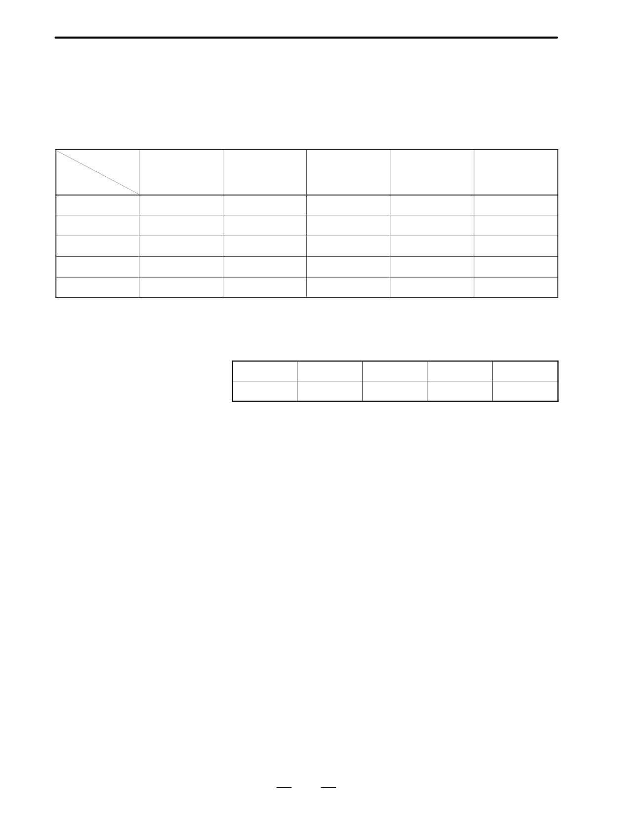
Number of
1
2
3
4
5
files
SRAM size
256KB
SRAM256A.FDB
1.5MB
SRAM0_5A.FDB
1.0MB
SRAM1_0A.FDB
SRAM1_0B.FDB
1.5MB
SRAM1_5A.FDB
SRAM1_5B.FDB
SRAM1_5C.FDB
2.5MB
SRAM2_5A.FDB
SRAM2_5B.FDB
SRAM2_5C.FDB
SRAM2_5D.FDB
SRAM2_5E.FDB
2
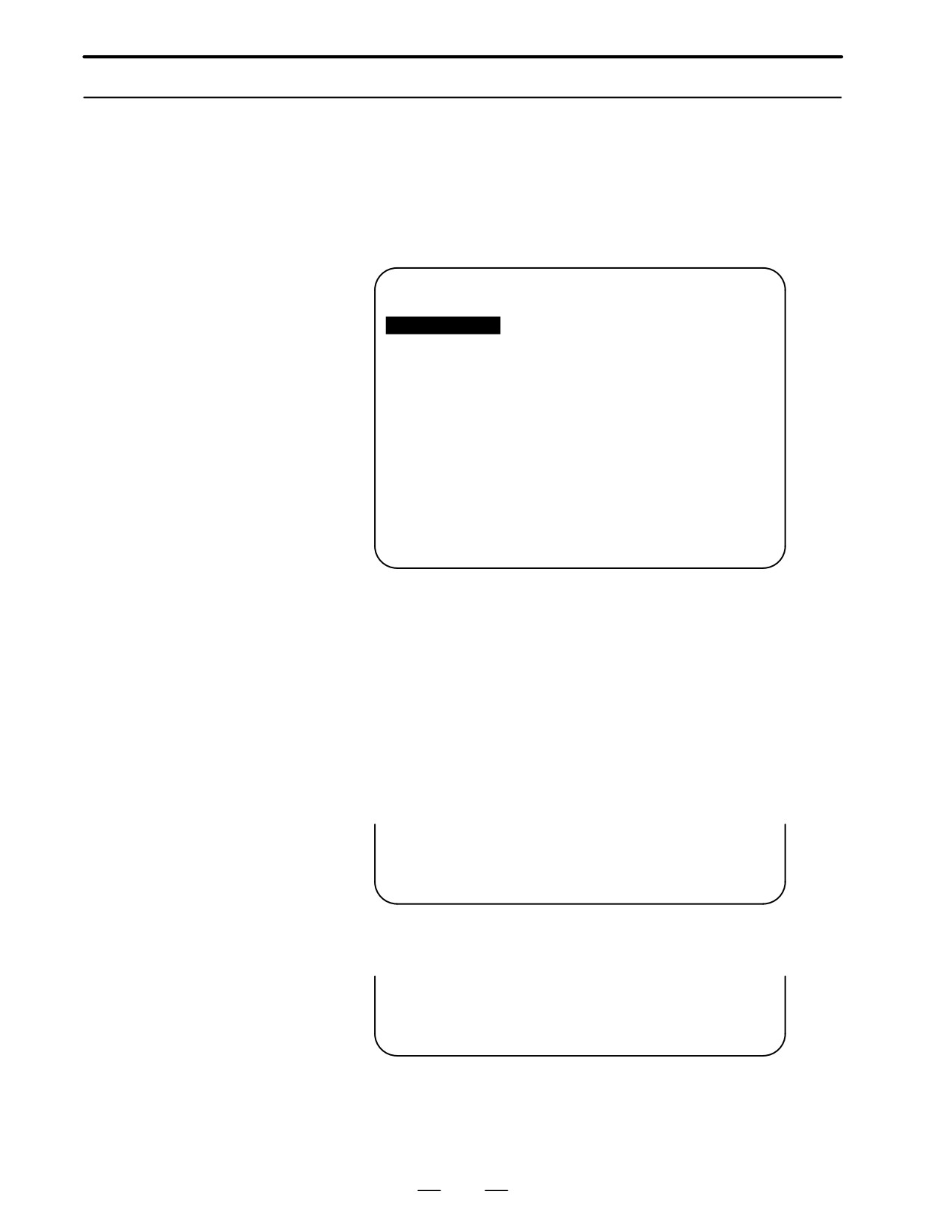
When the OPT2, OPT3, or LCB board is installed in addition to the main
board
The backup file for SRAM on the OPT2, OPT3, or LCB board will have the
following extension:
Board
MAIN
OPT2
OPT3
LCB
Extension
FDB
OP2
OP3
LCB
500
B-62445E/03
APPENDIX
D. BOOT SYSTEM
D.2.6
MEMORY CARD FILE
DELETE Screen
D Description
This screen is used to delete a file from a memory card.
D Screen configuration
(1)
SRAM DATA LOADING
1/1
FILE DIRECTORY
(2)
B1A1EO2B.ROM
B1A1E02O.ROM
(3)
END
(4)
*** MESSAGE ***
SELECT FILE AND HIT SELECT KEY.
[ SELECT ][ YES
][ NO
][ UP
][ DOWN
]
1
: Screen title. Tlhe current page number (n) and the total number
of pages (m) are displayed, in n/m format, at the right end.
2
: Files on the memory card
3
: Option for returning to the previous menu
4
: Message
D Operating procedure
1
Press the [SELECT] key to select the name of the file to be deleted
from the memory card.
2
The system displays the following confirmation message. Press the
[YES] key.
*** MESSAGE ***
DELETE OK ? HIT YES OR NO.
3
When deletion completes normally, the following message is
displayed. Pless [SELECT]key.
*** MESSAGE ***
DELETE COMPLETE. HIT SELECT KEY.
D Others
1
When the memory card contains nine or more files
Display the desired page, following the procedure given in the
description of the SYSTEM DATA LOADING screen.
501
D. BOOT SYSTEM
APPENDIX
B-62445E/03
D.2.7
MEMORY CARD
FORMAT Function
D Description
This function is used to format a memory card. Memory cards must be
formatted before they can be used for the first time or before they can be
re-used after their data has been destroyed or lost because of, for example,
battery failure.
D Operating procedure
1 From the SYSTEM MONITOR MAIN MENU screen, select ”7.
MEMORY CARD FORMAT.”
2
The system displays the following confirmation message.
Press the [YES] key.
*** MESSAGE ***
MEMORY CARD FORMAT OK ? HIT YES OR NO.
3
The system displays the following message during formatting :
*** MESSAGE ***
FORMATTING MEMORY CARD.
4
When a card has been formatted normally, the system display the
⋅
following message.
⋅
Press the [SELECT] key.
*** MESSAGE ***
FORMAT COMPLETE. HIT SELECT KEY.
502
B-62445E/03
APPENDIX
D. BOOT SYSTEM
D.2.8
LOAD BASIC SYSTEM
Function
D Description
The function is used to terminate the boot system and activate the CNC.
D Operating procedure
From the MAIN MENU screen, select “9. END.” The system displays
the “ARE YOU SURE? HIT YES OR NO” message. To terminate the
boot system and activate the CNC, press the [YES] soft key. Pressing
the [NO] key cancels this operation.
*** MESSAGE ***
ARE YOU SURE ? HIT YES OR NO.
[ SELECT ][ YES
][ NO
][ UP
][ DOWN
]
1
After pressing the [YES] soft key
The system checks the NC BASIC system file in the flash ROM. The
system displays the following message :
*** MESSAGE ***
CHECK CNC BASIC SYSTEM.
[ SELECT ][ YES
][ NO
][ UP
][ DOWN
]
When the NC BASIC system file is found to be normal, the system
sends the system file to DRAM and starts the NC basic system. During
loading, the system blinks the following message.
*** MESSAGE ***
LOADING BASIC TO DRAM
[ SELECT ][ YES
][ NO
][ UP
][ DOWN
]
If the contents of the NC BASIC SYSTEM file are found to have been
damaged or destroyed, the system returns to the processing selection
state, in exactly the same way as when the [NO] soft key is pressed.
2
If the [NO] soft key is pressed, the system returns to the processing
selection state as shown below :
*** MESSAGE ***
SELECT MENU AND HIT [SELECT] KEY.
[ SELECT ][ YES
][ NO
][ UP
][ DOWN
]
503
D. BOOT SYSTEM
APPENDIX
B-62445E/03
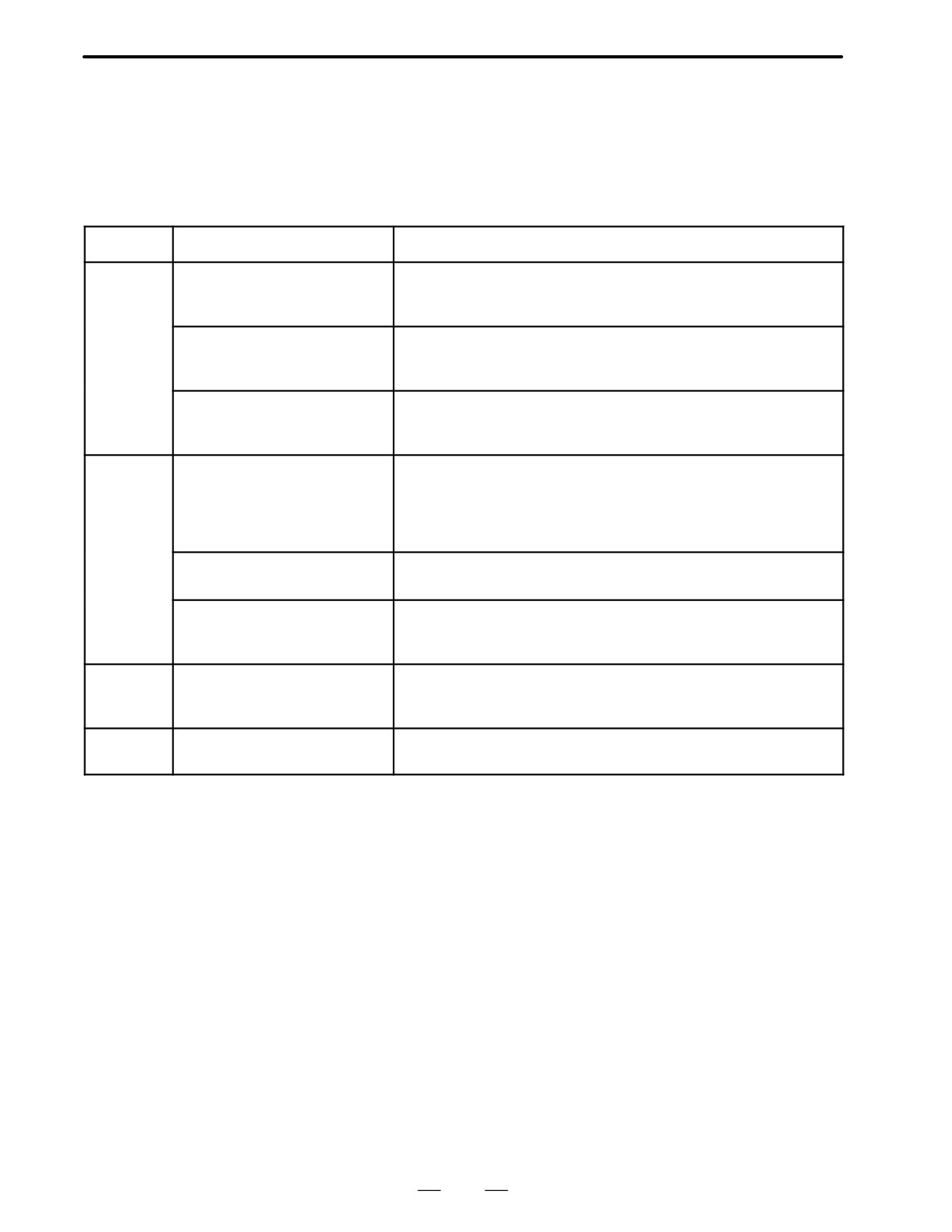
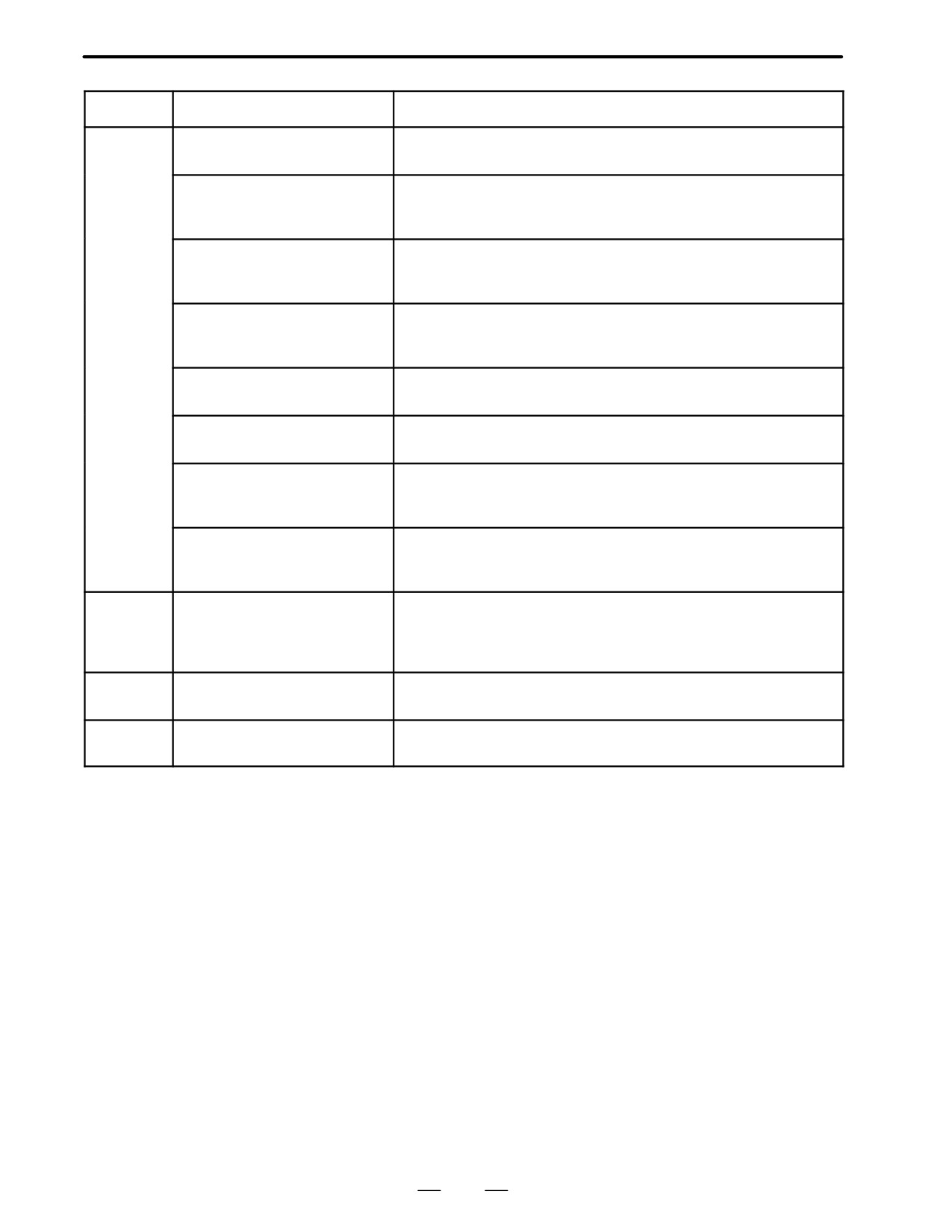
The following table lists and explains error messages in alphabetical
D.3
order.
ERROR MESSAGES
AND REQUIRED
ACTIONS
Message
Description and required action
D
DELETE ERROR.
An attempt to delete a file from flash memory was unsuccessful. Retry
HIT SELECT KEY.
the deletion. If the second attempt also fails, the flash memory may
have been damaged or destroyed. Replace the flash memory module.
DEVICE ERROR (CNC x)
An attempt to write data to flash memory was unsuccessful. Retry the
write operation. If the second attempt also fails, the flash memory may
have been damaged or destroyed. Repalce the flash memory module.
D-RAM OR S-RAM PARITY
Invalid data has been found in the RAM area. If the RAM was not
cleared after being installed, subsequently attempting backup may
stop the BOOT SYSTEM and cause this message to be output.
F
FILE SAVE ERROR.
An attempt to write a file to a memory card was unsuccessful. Check
HIT SELECT KEY.
that the memory card is not damaged.
Note) Check that the memory card’s battery is not exhusted, that its
circuitry has not been damaged, and that it is securely inserted into its
slot.
FLASH MEMORY NO SPACE
There is insufficient free flash memory to store the selected file. De-
lete any unnecessary files from flash memory.
FLASH ROM MODULE NOT EX-
The flash memory module is not mounted on that CNC system. Put
IST.
the flash memory module on the board.
HIT SELECT.
I
ILLEGAL FORMAT FILE
The selected file cannot be read into flash memory. The selected file
or the header information for flash memory may have been damaged
or destroyed.
L
LOADING ERROR.
An error occurred while loading data into flash memory.
HIT SELECT KEY.
Do not touch the memory card while loading data.
504
B-62445E/03
APPENDIX
D. BOOT SYSTEM
Message
Description and required action
M
MAX EXTENSION OVER.
The extension number added to a file name exceeds 031. Delete any
HIT SELECT KEY.
unnecessary backup files from the memory card.
MEMORY CARD BATTERY
The memory card’s battery is exhausted. Replace the battery.
ALARM.
HIT SELECT.
MEMORY CARD FULL.
The memory card is full. Delete any unnecessary files from the
HIT SELECT KEY.
memory card. Alternatively, replace the memory card with another
card having sufficient free space.
MEMORY CARD MOUNT ER-
The memory card could not be accessed. Check that the memory
ROR.
card is normal.
HIT SELECT KEY
MEMORY CARD NOT EXIST.
The memory card is not inserted into its slot. Check that the memory
HIT SELECT KEY.
card is pushed fully home.
MEMORY CARD PROTEC-
Although writing to the memory card was selected, the write inhibit
TED.HIT SELECT KEY.
switch is set. Disable the write inhibit switch.
MEMORY CARD TYPE IS NOT
Write has been attempted to an incompatible flash memory card. Use
AVAILABLE.
only the flash memory cards recommended by FANUC. Recom-
mended flash memory cards are listed in the ordering list.
MEMORY CARD WRITE ER-
Access to the memory card has failed. Check whether the memory
ROR.
card is defective.
HIT SELECT KEY.
P
PLEASE FORMAT FLASH TYPE
It is not possible to delete only specific files from a flash memory card,
CARD.HIT SEL.
due to the characteristics of the memory used. To delete a file it is
necessary to delete all files on the card, by using the FORMAT func-
tion.
R
ROM PARITY ERROR:
The NC BASIC is parity error. Check that mounted flash memory
NC BASIC. HIT SELECT.
module contains NC BASIC file.
S
SRAM DATA BACKUP ERROR.
An attempt to write a backup file to a memory card failed.
HIT SELECT KEY.
Check that the memory card is normal.
505

E. NOTATION OF MDI KEYS
APPENDIX
B-62445E/03
NOTATION OF MDI KEYS
E
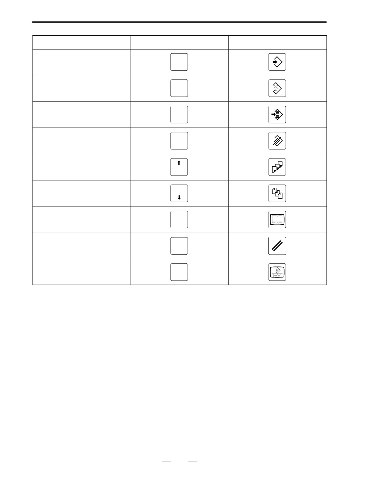
Series 16/18/160/180-MODEL B have two types of MDI keypads : English type and Symbolic type.
The table below shows correspondence between English keys and Symbolic keys.
This manual uses English type in the text.
Therefore when a user uses Symbolic type MDI keypads and encounters an English key in the text, please refer
to the correspondence table shown below.
Name
English key
Symbolic key
CANCEL key
CAN
POSITION key
POS
PROGRAM key
PROG
OFFSET/
OFFSET
SETTING key
SETTING
CUSTOM key
CUSTOM
SYSTEM key
SYSTEM
MESSAGE key
MESSAGE
GRAPH key
GRAPH
CNC
CNC/MMC key
MMC
SHIFT key
SHIFT
506
B-62445E/03
APPENDIX
E. NOTATION OF MDI KEYS
Name
English key
Symbolic key
INPUT key
INPUT
ALTER key
ALTER
INSERT key
INSERT
DELETE key
DELETE
PAGE UP key
PAGE
PAGE
PAGE DOWN key
HELP key
HELP
RESET key
RESET
CUSTOM
CUSTOM/GRAPH key
GRAPH
507