FANUC Series 16 / 160 / 18 / 180 – Model B. Maintenance Manual - page 15
A. I/O UNIT MODEL A
APPENDIX
B-62445E/03
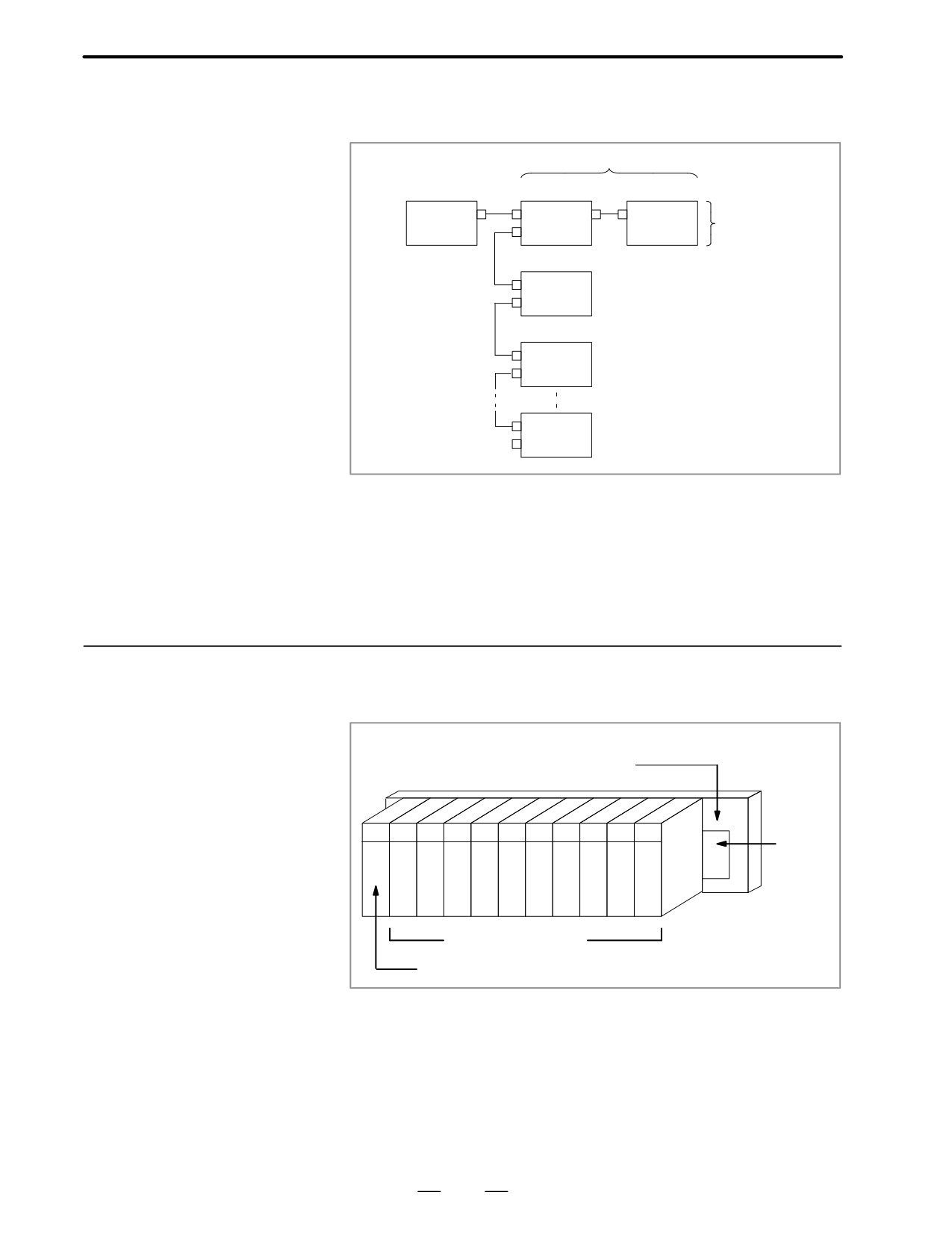
Up to 16 FANUC I/O Unit-MODEL A groups can be connected to a CNC
A.1
through the FANUC I/O Link high-speed serial interface.
SYSTEM
CONFIGURATION
Slave
Master
Base 0
Base 1
FS16/18
I/O UNIT
I/O UNIT
Group 0
I/O UNIT
Group 1
Group 2
Group 15
* The number and types of slave units that can be connected for each
group are as follows :
⋅
Up to two I/O Units
⋅
One Power Mate
⋅
One Operator’s-panel connection unit
⋅
One Series 0-C
A.2
HARDWARE
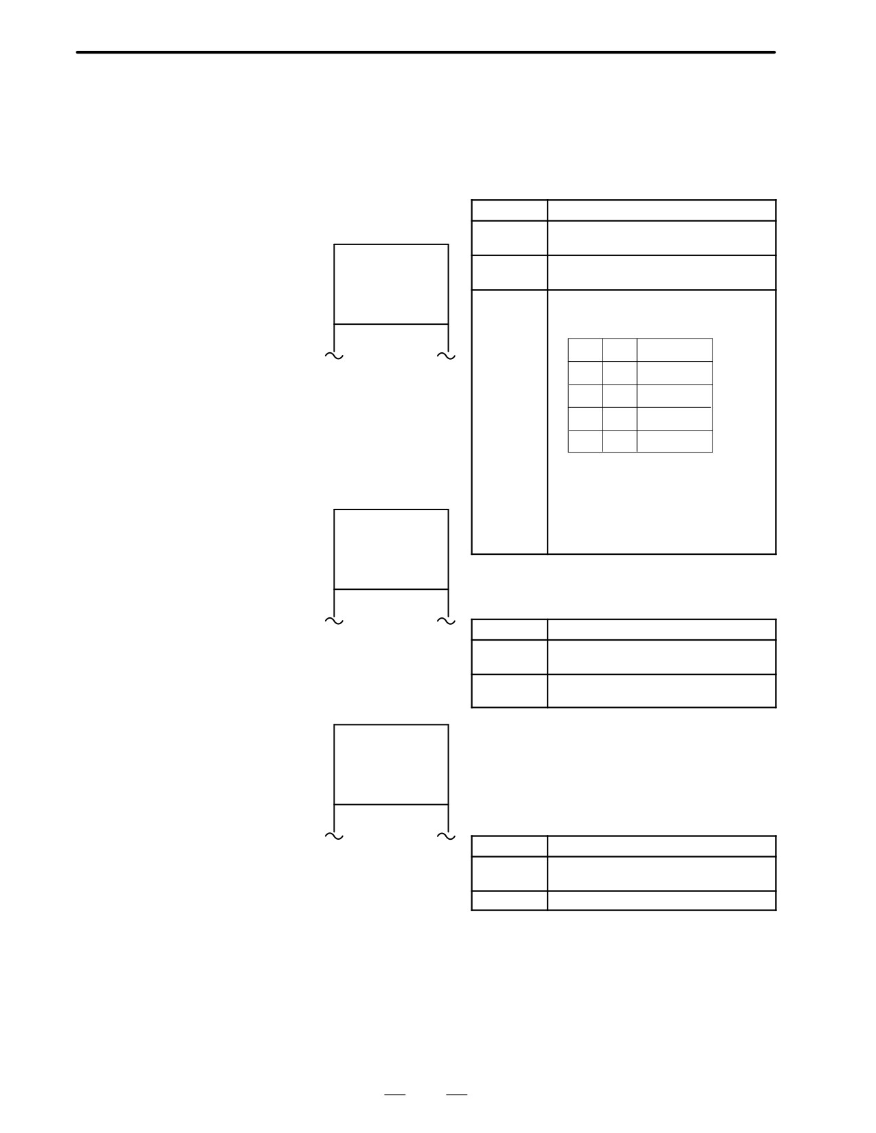
Base unit
CONFIGURATION
(ABU05A or ABU10A)
Label
(indicat-
ing the
specifi-
cations)
Input /Output modules
Interface module (AIF01A or AIF01B)
426
B-62445E/03
APPENDIX
A. I/O UNIT MODEL A
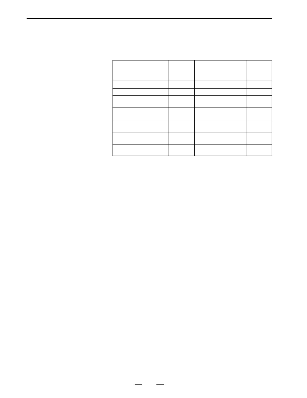
Modules having up to 16 input/output points are provided with LEDs to
A.3
indicate their statuses.
LED INDICATION
Use these LED’s to assist you with troubleshooting.
AIF01A
Symbol
Description
PWR
Indicates that the internal 24 VDC power
supply is operating normally.
fPWR fLINK
LINK
Indicates that the I/O Link is operating nor-
mally.
fBA1
BA0
Indicates the number of the base from which
fBA0
BA1
data is being transferred.
AIF01A
BA1
BA0
Base number
f
f
Base #0
f
F
Base #1
F
f
Base #2
F
F
Base #3
F:On
f:Off
If the LINK went on once, but then falled,
these LEDs indicate the number of the base
fPWR fLINK
that was transferring data when the error oc-
curred.
AIF01B
AIF01B
Symbol
Description
PWR
Indicates that the internal 24 VDC power
supply is operating normally.
LINK
Indicates that the I/O Link is operating nor-
mally.
A 0 1 2 3 4 5 6 7
F
B 0 1 2 3 4 5 6 7
Input / Output modules
Afffff
(with up to 16 input /
Symbol
Description
output points)
A0 - 7
Indicate the state of an input / output signal
B0 - 7
(LED on : signal on, LED off : signal off )
F
Indicates that the internal fuse has blown
427
A. I/O UNIT MODEL A
APPENDIX
B-62445E/03
The following modules provide the corresponding protection fuses. If a
A.4
fuse blows for any reason , such as the short-circuiting of a cable
FUSES
connected to a load, firt remove the cause of the problem, then replace the
fuse.
Indication
of whether
Rated cur-
Module
Parts number of fuse
a fuse has
rent
blown
AIF01A Interface module
PWR off
A60L-0001-0290#LM32
3.2A
AIF01B Interface module
PWR off
A60L-0001-0290#LM32
3.2A
A0D08C Output module
F on
A60L-0001-0260#5R00
5A
(8 DC points)
A0D08D Output module
F on
A60L-0001-0260#5R00
5A
(8 DC points)
A0A05E Output module
F on
A60L-0001-0276#3.15
3.15A
(5 AC points)
A0A08E Output module
F on
A60L-0001-0276#3.15
3.15A
(8 AC points)
A0A12F Output module
F on
A60L-0001-0276#3.15
3.15A
(12 AC points)
428
B-62445E/03
APPENDIX
A. I/O UNIT MODEL A
A.5
REMOVING A
PRINTED CIRCUIT
BOARD
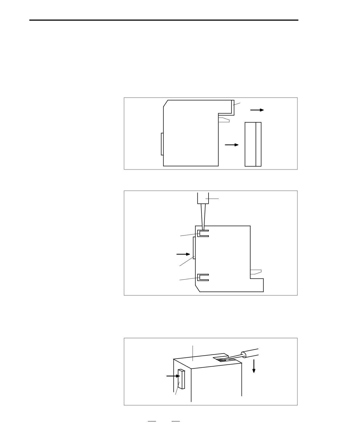
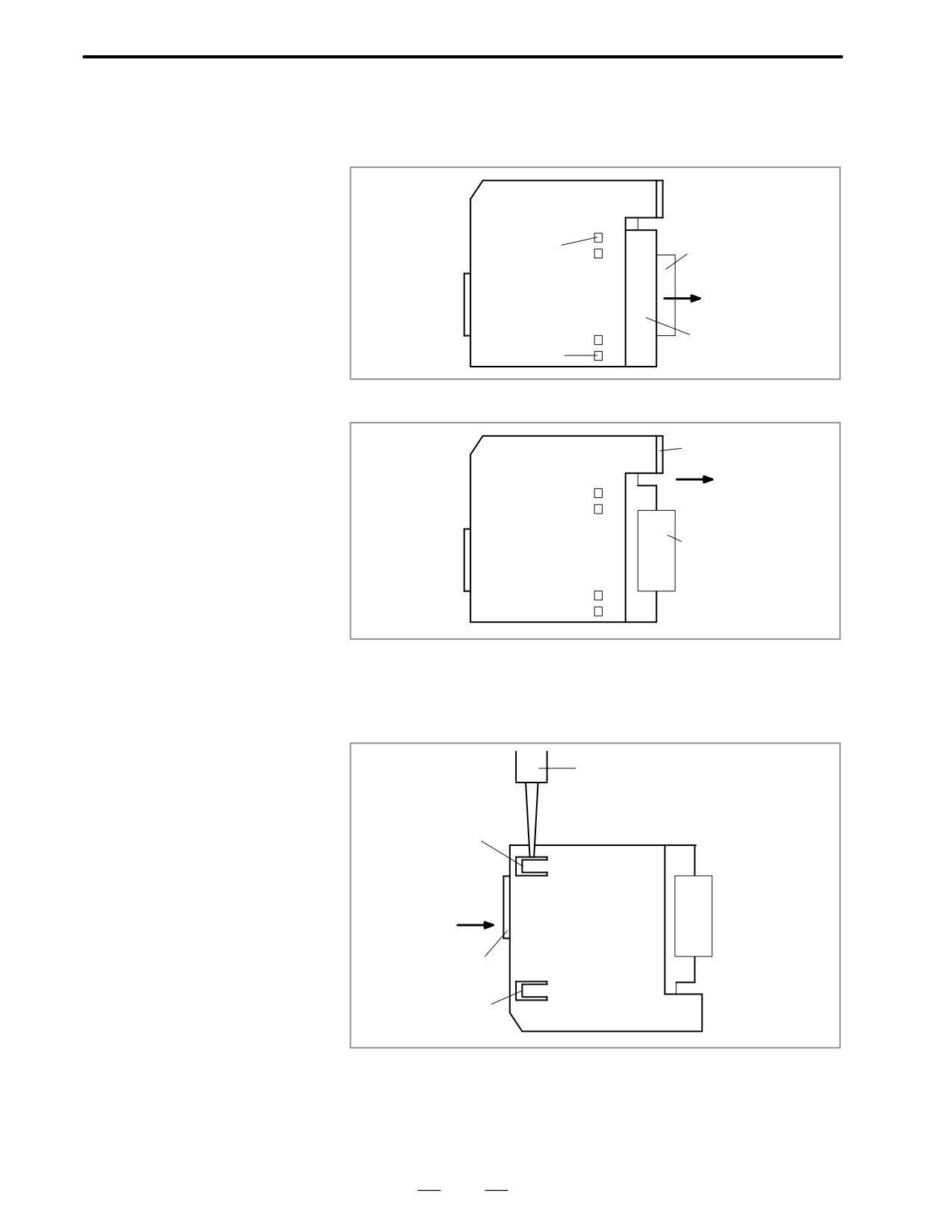
D Removing a
1
Remove the terminal box, if necessary.
terminal-box-type
2
Remove the LED cap by pulling it in the direction indicated by the
input/output module
arrow.
LED cap
(2)
Ter-
(1)
mi-
nal
box
3
While pushing the connector in the direction indicated by the arrow,
use a screwdriver to release the two claws on the module case.
Screwdriver
Claw
Connector
Claw
4
As shown on the right, insert a screwdriver into the gap between the
module case and the connector of the terminal box. To remove the
printed circuit board, push the connector in the direction indicated by
arrow B while pushing the screwdriver in the direction indicated by
arrow A
Underside of the module
B
A
Connector
429
A. I/O UNIT MODEL A
APPENDIX
B-62445E/03
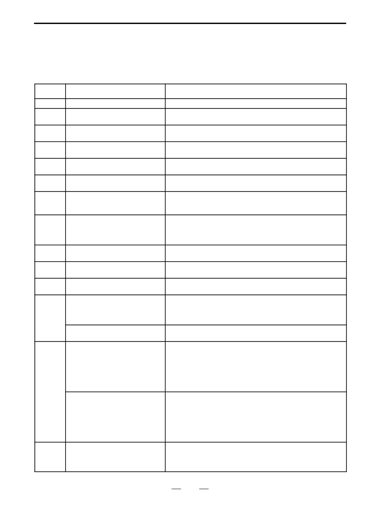
D Removing a
connector-type
1
To remove the cover, pull it in the direction indicated by the arrow,
input/output module
while using a screwdriver to release claws A and B on both sides.
A
Connector
Cover
B
2
To remove the LED cap, pull it in the direction indicated by the arrow.
LED cap
Connector
3
While pushing the connector in the direction indicated by the arrow,
use a screwdriver to release the two or four claws on the module case.
Then, remove the printed circuit board by pushing the connector in the
direction indicated by the arrow.
Screwdriver
Claw
Connector
Claw
430

B-62445E/03
APPENDIX
B. ALARM LIST
ALARM LIST
B
B.1LIST OF ALARM CODES
(1) Program errors/Alarms on program and
operation (P/S alarm) .
432
(2) Background edit alarm .
448
(3) Absolute pulse coder (APC) alarm .
448
(4) Serial pulse coder (SPC) alarms .
449
(5) Servo alarms .
450
(6) Over travel alarms .
452
(7) Overheat alarms .
452
(8) Rigid tapping alarms .
453
(9) Serial spindle alarms .
453
(10) System alarms .
455
B.2LIST OF ALARMS (PMC)
(1) Alarm messages (PMC) .
456
(2) Alarm messages (For EDIT 1) .
460
(3) Alarm messages (For I/O) .
462
B.3SPINDLE ALARMS (SERIAL SPINDLE) .
463
B.4SPINDLE ALARMS (ANALOG INTERFACE)
(S SERIES AC SPINDLE) .
468
431
B. ALARM LIST
APPENDIX
B-62445E/03
B.1
LIST OF ALARM
CODES
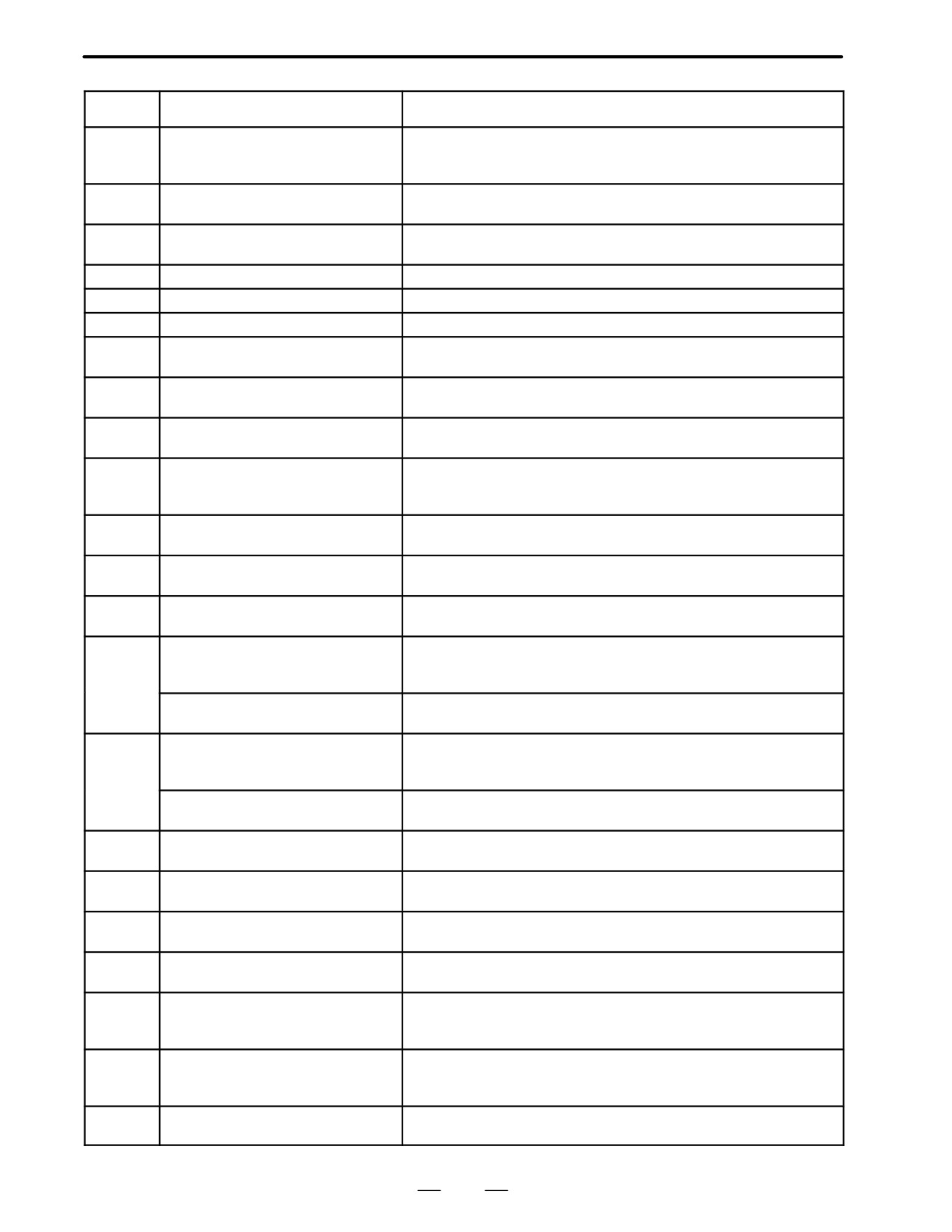
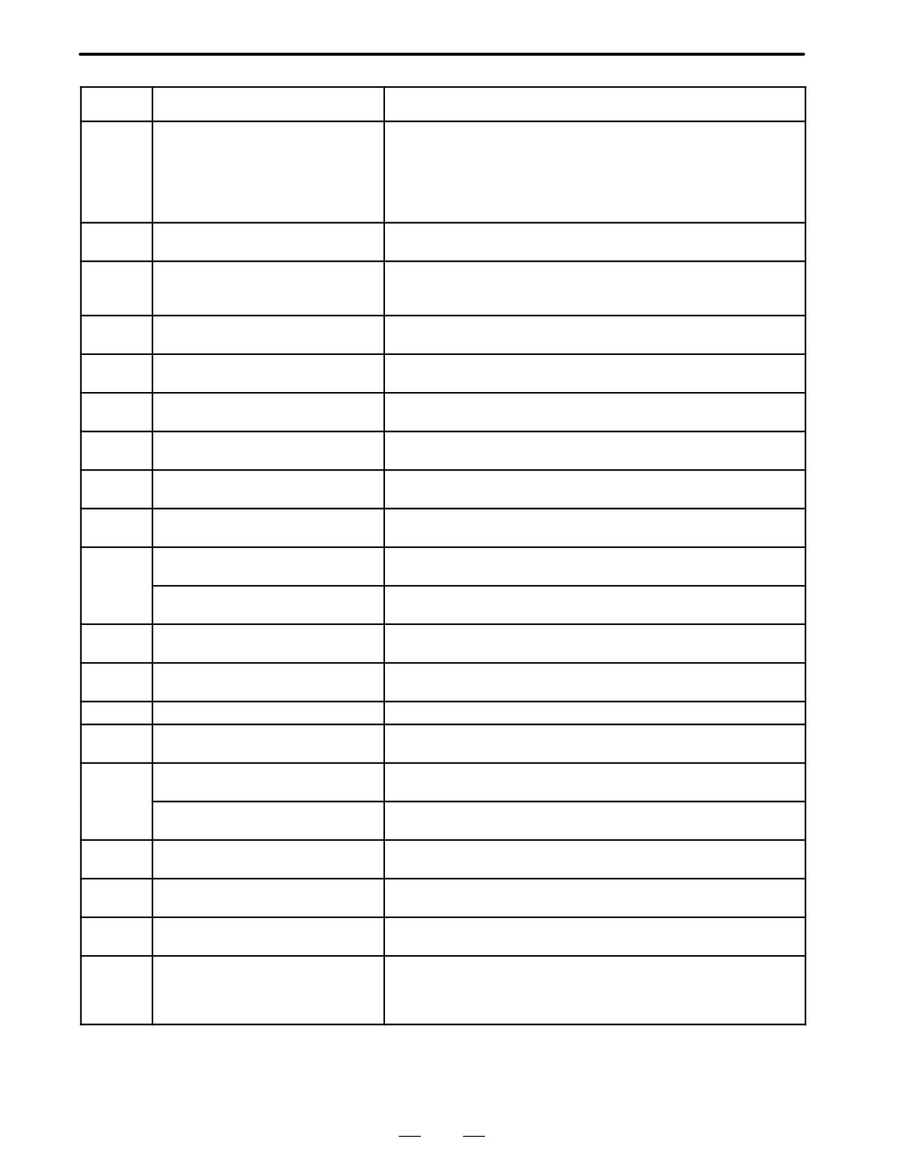
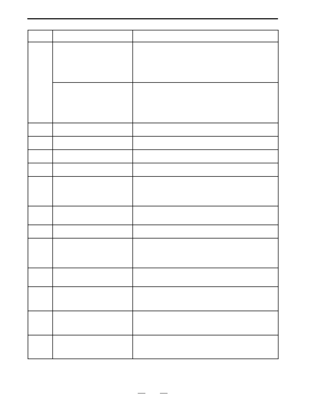
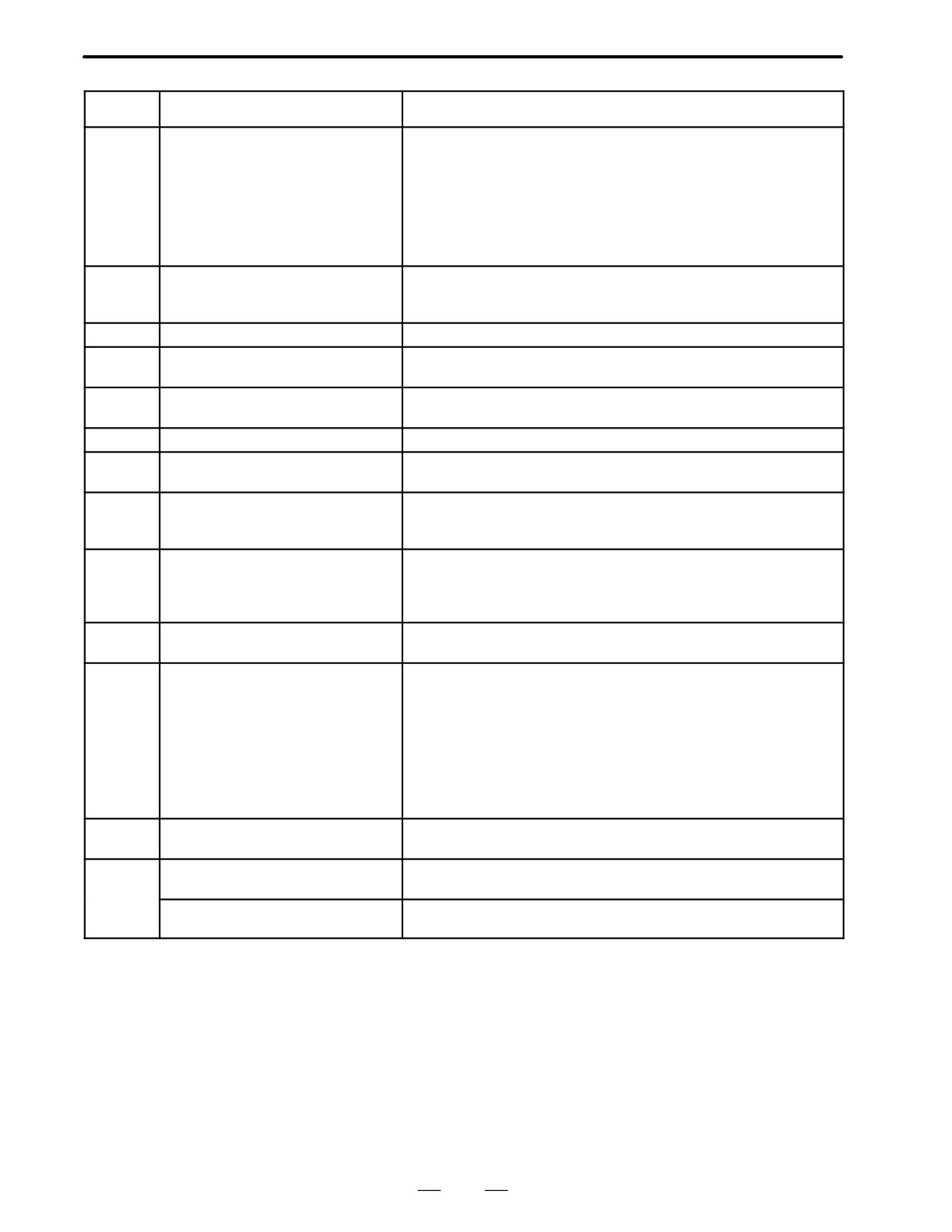
(1) Program errors /Alarms on program and operation (P/S alarm)
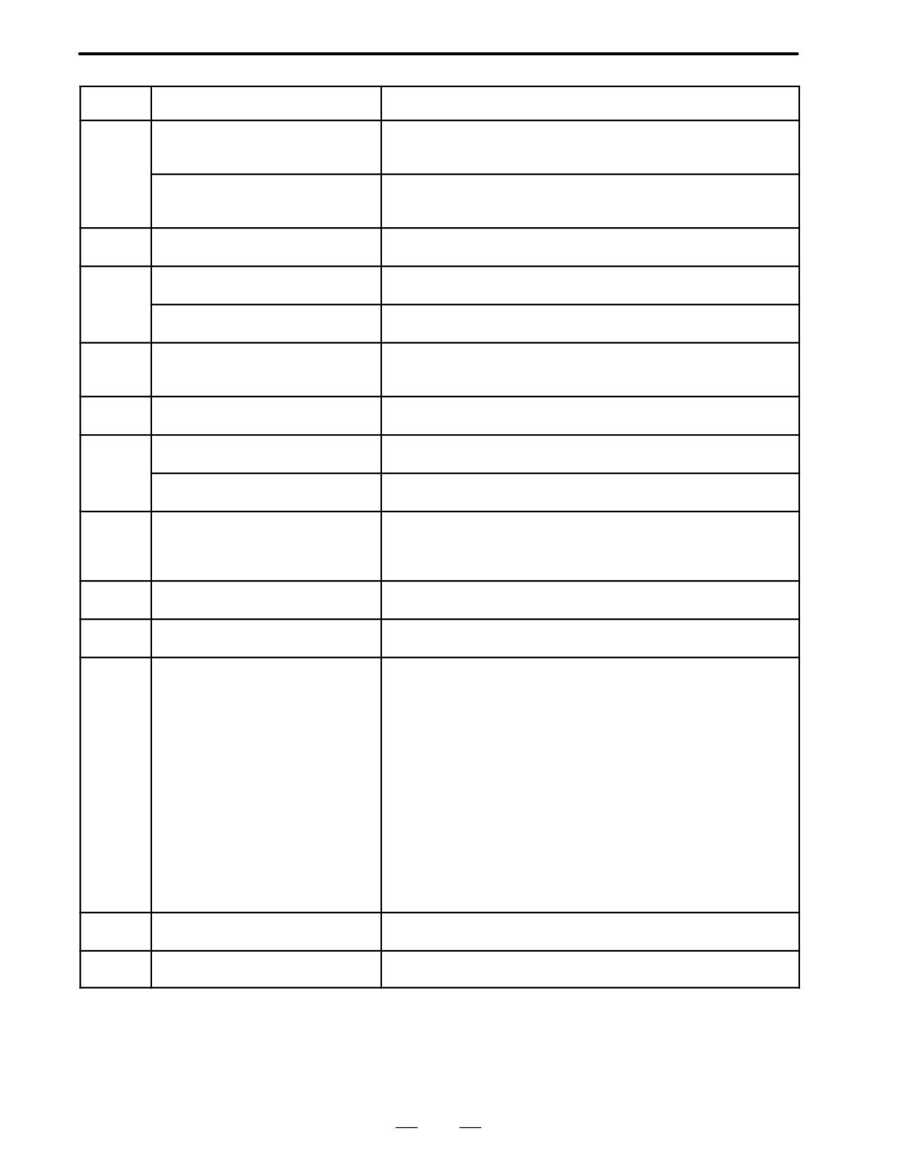
Number
Message
Contents
000
PLEASE TURN OFF POWER
A parameter which requires the power off was input, turn off power.
001
TH PARITY ALARM
TH alarm (A character with incorrect parity was input).
Correct the tape.
002
TV PARITY ALARM
TV alarm (The number of characters in a block is odd). This alarm will
be generated only when the TV check is effective.
003
TOO MANY DIGITS
Data exceeding the maximum allowable number of digits was input.
(Refer to the item of max. programmable dimensions.)
004
ADDRESS NOT FOUND
A numeral or the sign “ - ” was input without an address at the begin-
ning of a block. Modify the program .
005
NO DATA AFTER ADDRESS
The address was not followed by the appropriate data but was fol-
lowed by another address or EOB code. Modify the program.
006
ILLEGAL USE OF NEGATIVE SIGN
Sign “ - ” input error (Sign “ - ” was input after an address with which
it cannot be used. Or two or more “ - ” signs were input.)
Modify the program.
007
ILLEGAL USE OF DECIMAL POINT
Decimal point “ . ” input error (A decimal point was input after an ad-
dress with which it can not be used. Or two decimal points were in-
put.)
Modify the program.
009
ILLEGAL ADDRESS INPUT
Unusable character was input in significant area.
Modify the program.
010
IMPROPER G-CODE
An unusable G code or G code corresponding to the function not
provided is specified. Modify the program.
011
NO FEEDRATE COMMANDED
Feedrate was not commanded to a cutting feed or the feedrate was
inadequate. Modify the program.
ILLEGAL LEAD COMMAND
In variable lead threading, the lead incremental and decremental out-
(T series)
putted by address K exceed the maximum command value or a com-
mand such that the lead becomes a negative value is given.
014
Modify the program.
CAN NOT COMMAND G95
A synchronous feed is specified without the option for threading /
(M series)
synchronous feed.
TOO MANY AXES COMMANDED
An attempt was made to move the machine along the axes, but the
number of the axes exceeded the specified number of axes con-
trolled simultaneously. Alternatively, in a block where where the skip
function activated by the torque-limit reached signal (G31 P99/P98)
was specified, either moving the machine along an axis was not spe-
cified, or moving the machine along multiple axes was specified.
Specify movement only along one axis.
015
TOO MANY AXES COMMANDED
An attempt has been made to move the tool along more than the
(T series)
maximum number of simultaneously controlled axes. Alternatively,
no axis movement command or an axis movement command for two
or more axes has been specified in the block containing the com-
mand for skip using the torque limit signal (G31 P99/98). The com-
mand must be accompanied with an axis movement command for a
single axis, in the same block.
020
OVER TOLERANCE OF RADIUS
In circular interpolation (G02 or G03), difference of the distance be-
tween the start point and the center of an arc and that between the
end point and the center of the arc exceeded the value specified in
parameter No. 3410.
432
B-62445E/03
APPENDIX
B. ALARM LIST
Number
Message
Contents
021
ILLEGAL PLANE AXIS COMMAN-
An axis not included in the selected plane (by using G17, G18, G19)
DED
was commanded in circular interpolation. Modify the program.
022
NO CIRCLE RADIUS
The command for circular interpolation lacks arc radius R or coordi-
nate I, J, or K of the distance between the start point to the center of
the arc.
023
ILLEGAL RADIUS COMMAND
In circular interpolation by radius designation, negative value was
(T series)
commanded for address R. Modify the program.
025
CANNOT COMMAND F0 IN
F0 (fast feed) was instructed by F1 -digit column feed in circular in-
G02/G03 (M series)
terpolation. Modify the program.
027
NO AXES COMMANDED IN
No axis is specified in G43 and G44 blocks for the tool length offset
G43/G44 (M series)
type C.
Offset is not canceled but another axis is offset for the tool length
offset type C. Modify the program.
028
ILLEGAL PLANE SELECT
In the plane selection command, two or more axes in the same direc-
tion are commanded.
Modify the program.
ILLEGAL OFFSET VALUE
The offset values specified by H code is too large.
(M series)
Modify the program.
029
ILLEGAL OFFSET VALUE
The offset values specified by T code is too large.
(T series)
Modify the program.
ILLEGAL OFFSET NUMBER
The offset number specified by D/H code for tool length offset or cut-
(M series)
ter compensation is too large. Modify the program.
030
ILLEGAL OFFSET NUMBER
The offset number in T function specified for tool offset is tool large.
(T series)
Modify the program.
031
ILLEGAL P COMMAND IN G10
In setting an offset amount by G10, the offset number following ad-
dress P was excessive or it was not specified.
Modify the program.
032
ILLEGAL OFFSET VALUE IN G10
In setting an offset amount by G10 or in writing an offset amount by
system variables, the offset amount was excessive.
NO SOLUTION AT CRC
A point of intersection cannot be determined for cutter compensation.
(M series)
Modify the program.
033
NO SOLUTION AT CRC
A point of intersection cannot be determined for tool nose radius
(T series)
compensation. Modify the program.
NO CIRC ALLOWED IN ST-UP /
The start up or cancel was going to be performed in the G02 or G03
EXT BLK (M series)
mode in cutter compensation C. Modify the program.
034
NO CIRC ALLOWED IN ST-UP /
The start up or cancel was going to be performed in the G02 or G03
EXT BLK (T series)
mode in tool nose radius compensation. Modify the program.
CAN NOT COMMANDED G39
G39 is commanded in cutter compensation B cancel mode or on the
(M series)
plane other than offset plane. Modify the program.
035
CAN NOT COMMANDED G31
Skip cutting (G31) was specified in tool nose radius compensation
(T series)
mode. Modify the program.
036
CAN NOT COMMANDED G31
Skip cutting (G31) was specified in cutter compensation mode.
(M series)
Modify the program.
CAN NOT CHANGE PLANE IN CRC
G40 is commanded on the plane other than offset plane in cutter
(M seires)
compensation B. The plane selected by using G17, G18 or G19 is
037
changed in cutter compensation C mode. Modify the program.
CAN NOT CHANGE PLANE IN NRC
The offset plane is switched in tool nose radius compensation.
(T seires)
Modify the program.
433
B. ALARM LIST
APPENDIX
B-62445E/03
Number
Message
Contents
INTERFERENCE IN CIRCULAR
Overcutting will occur in cutter compensation C because the arc start
BLOCK (M seires)
point or end point coincides with the arc center.
Modify the program.
038
INTERFERENCE IN CIRCULAR
Overcutting will occur in tool nose radius compensation because the
BLOCK (T series)
arc start point or end point coincides with the arc center.
Modify the program.
039
CHF/CNR NOT ALLOWED IN NRC
Chamfering or corner R was specified with a start-up, a cancel, or
(T series)
switching between G41 and G42 in tool nose radius compensation.
The program may cause overcutting to occur in chamfering or corner
R. Modify the program.
040
INTERFERENCE IN G90/G94
Overcutting will occur in tool nose radius compensation in canned
BLOCK (T series)
cycle G90 or G94. Modify the program.
INTERFERENCE IN CRC
Overcutting will occur in cutter compensation C. Two or more blocks
(M seires)
are consecutively specified in which functions such as the auxiliary
function and dwell functions are performed without movement in the
041
cutter compensation mode. Modify the program.
INTERFERENCE IN NRC
Overcutting will occur in tool nose radius compensation.
(T seires)
Modify the program.
042
G45/G48 NOT ALLOWED IN CRC
Tool offset (G45 to G48) is commanded in cutter compensation.
(M series)
Modify the program.
043
ILLEGAL T-CODE COMMAND
In a system using the DRILL-MATE with an ATC, a T code was not
(M series)
specified together with the M06 code in a block. Alternatively, the
Tcode was out of range.
044
G27-G30 NOT ALLOWED IN FIXED
One of G27 to G30 is commanded in canned cycle mode.
CYC (M sries)
Modify the program.
046
ILLEGAL REFERENCE RETURN
Other than P2, P3 and P4 are commanded for 2nd, 3rd and 4th refer-
COMMAND
ence position return command.
047
ILLEGAL AXIS SELECT
Two or more parallel axes (in parallel with a basic axis) have been
(M series)
specified upon start-up of three-dimensional tool compensation or
three-dimensional coordinate conversion.
048
BASIC 3 AXIS NOT FOUND
Start-up of three-dimensional tool compensation or three-dimen-
(M series)
sional coordinate conversion has been attempted, but the three basic
axes used when Xp, Yp, or Zp is omitted are not set in parameter No.
1022.
050
CHF/CNR NOT ALLOWED IN THRD
Optional chamfering or corner R is commanded in the thread cutting
BLK (M series)
block.
Modify the program.
CHF/CNR NOT ALLOWED IN THRD
Chamfering or corner R is commanded in the thread cutting block.
BLK(T series)
Modify the program.
051
MISSING MOVE AFTER CHF/CNR
Improper movement or the move distance was specified in the block
(M series)
next to the optional chamfering or corner R block.
Modify the program.
MISSING MOVE AFTER CHF/CNR
Improper movement or the move distance was specified in the block
(T series)
next to the chamfering or corner R block.
Modify the program.
CODE IS NOT G01 AFTER CHF/
The block next to the chamfering or corner R block is not G01,G02 or
CNR (M series)
G03.
Modify the program.
052
CODE IS NOT G01 AFTER CHF/
The block next to the chamfering or corner R block is not G01.
CNR (T series)
Modify the program.
434
B-62445E/03
APPENDIX
B. ALARM LIST
Number
Message
Contents
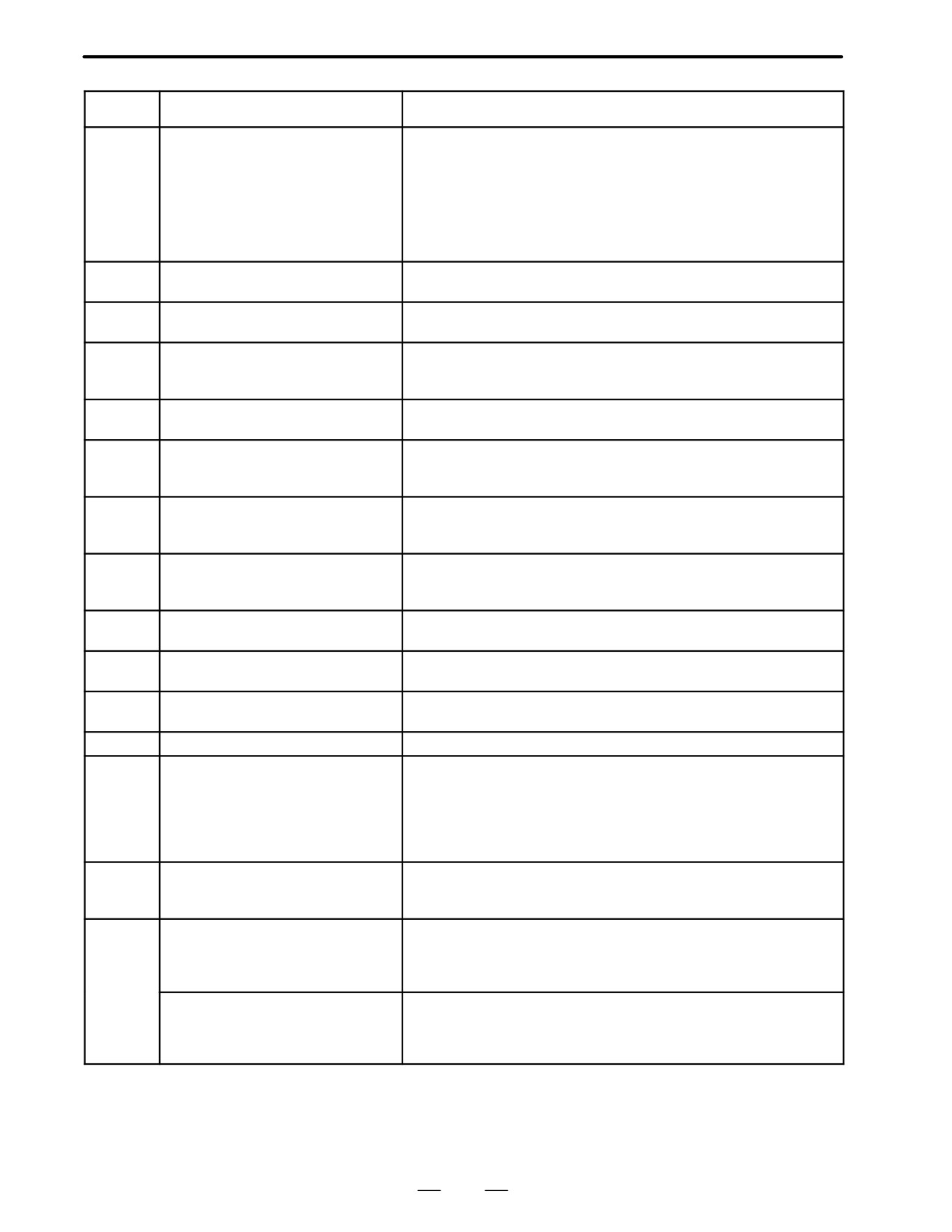
TOO MANY ADDRESS COM-
For systems without the arbitary angle chamfering or corner R cut-
MANDS (M series)
ting, a comma was specified. For systems with this feature, a comma
was followed by something other than R or C Correct the program.
053
TOO MANY ADDRESS COM-
In the chamfering and corner R commands, two or more of I, K and R
MANDS (T seires)
are specified. Otherwise, the character after a comma(”,”) is not C or
R in direct drawing dimensions programming. Modify the program.
NO TAPER ALLOWED AFTER CHF/
A block in which chamfering in the specified angle or the corner R
054
CNR
was specified includes a taper command. Modify the program.
MISSING MOVE VALUE IN CHF/
In the arbitrary angle chamfering or corner R block, the move dis-
CNR (M series)
tance is less than chamfer or corner R amount.
055
MISSING MOVE VALUE IN CHF/
In chamfering or corner R block, the move distance is less than
CNR (T series)
chamfer or corner R amount.
056
NO END POINT & ANGLE IN CHF/
Neither the end point nor angle is specified in the command for the
CNR (T series)
block next to that for which only the angle is specified (A). In the
chamfering comman, I(K) is commanded for the X(Z) axis.
057
NO SOLUTION OF BLOCK END
Block end point is not calculated correctly in direct dimension drawing
(T series)
programming.
END POINT NOT FOUND
In a arbitrary angle chamfering or corner R cutting block, a specified
(M series)
axis is not in the selected plane. Correct the program.
058
END POINT NOT FOUND
Block end point is not found in direct dimension drawing program-
(T series)
ming.
059
PROGRAM NUMBER NOT FOUND
In an external program number search, a specified program number
was not found. Otherwise, a program specified for searching is being
edited in background processing. Check the program number and
external signal. Or discontinue the background eiting.
060
SEQUENCE NUMBER NOT FOUND
Commanded sequence number was not found in the sequence num-
ber search. Check the sequence number.
061
ADDRESS P/Q NOT FOUND IN
Address P or Q is not specified in G70, G71, G72, or G73 command.
G70-G73 (T series)
Modify the program.
062
ILLEGAL COMMAND IN G71-G76
1. The depth of cut in G71 or G72 is zero or negative value.
(T series)
2. The repetitive count in G73 is zero or negative value.
3. the negative value is specified to Δi or Δk is zero in G74 or G75.
4. A value other than zero is specified to address U or W though Δi
or Δk is zero in G74 or G75.
5. A negative value is specified to Δd, thoughthe relief direction in
G74 or G75 is determined.
6. Zero or a negative value is specified to the height of thread or
depth of cut of first time in G76.
7. The specified minimum depth of cut in G76 is greater than the
height of thread.
8. An unusable angle of tool tip is specified in G76.
Modify the program.
063
SEQUENCE NUMBER NOT FOUND
The sequence number specified by address P in G70, G71, G72, or
(T series)
G73 command cannot be searched. Modify the program.
064
SHAPE PROGRAM NOT MONOTO-
A target shape which cannot be made by monotonic machining was
NOUSLY (T series)
specified in a repetitive canned cycle (G71 or G72).
435
B. ALARM LIST
APPENDIX
B-62445E/03
Number
Message
Contents
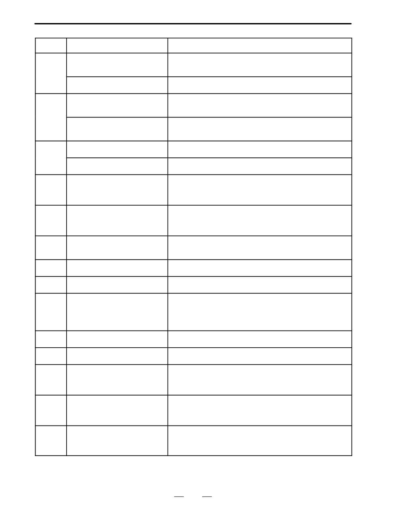
065
ILLEGAL COMMAND IN G71-G73
1. G00 or G01 is not commanded at the block with the sequence
(T series)
number which is specified by address P in G71, G72, or G73
command.
2. Address Z(W) or X(U) was commanded in the block with a
sequence number which is specified by address P in G71 or G72,
respectively.
Modify the program.
066
IMPROPER G-CODE IN G71-G73
An unallowable G code was commanded beween two blocks speci-
(T series)
fied by address P in G71, G72, or G73. Modify the program.
067
CAN NOT ERROR IN MDI MODE
G70, G71, G72, or G73 command with address P and Q.
(T series)
Modify the program.
069
FORMAT ERROR IN G70-G73
The final move command in the blocks specified by P and Q of G70,
(T series)
G71, G72, and G73 ended with chamfering or corner R.
Modify the program.
070
NO PROGRAM SPACE IN
The memory area is insufficient.
MEMORY
Delete any unnecessary programs, then retry.
071
DATA NOT FOUND
The address to be searched was not found. Or the program with
specified program number was not found in program number search.
Check the data.
072
TOO MANY PROGRAMS
The number of programs to be stored exceeded 63 (basic), 125 (op-
tion), 200 (option), 400 (option) or 1000 (option). Delete unnecessary
programs and execute program registeration again.
073
PROGRAM NUMBER ALREADY IN
The commanded program number has already been used.
USE
Change the program number or delete unnecessary programs and
execute program registeration again.
074
ILLEGAL PROGRAM NUMBER
The program number is other than 1 to 9999.
Modify the program number.
075
PROTECT
An attempt was made to register a program whose number was pro-
tected.
076
ADDRESS P NOT DEFINED
Address P (program number) was not commanded in the block which
includes an M98, G65, or G66 command. Modify the program.
077
SUB PROGRAM NESTING ERROR
The subprogram was called in five folds. Modify the program.
078
NUMBER NOT FOUND
A program number or a sequence number which was specified by
address P in the block which includes an M98, M99, M65 or G66 was
not found. The sequence number specified by a GOTO statement
was not found. Otherwise, a called program is being edited in back-
ground processing. Correct the program, or discontinue the back-
ground editing.
079
PROGRAM VERIFY ERROR
In memory or program collation,a program in memory does not agree
with that read from an external I/O device. Check both the programs
in memory and those from the external device.
G37 ARRIVAL SIGNAL NOT AS-
In the automatic tool length measurement function (G37), the mea-
SERTED
surement position reach signal (XAE, YAE, or ZAE) is not turned on
(M series)
within an area specified in parameter 6254 6255 (value ε).
This is due to a setting or operator error.
080
G37 ARRIVAL SIGNAL NOT AS-
In the automatic tool compensation function (G36, G37), the mea-
SERTED
surement position reach signal (XAE or ZAE) is not turned on within
(T series)
an area specified in parameter 6254 (value ε).
This is due to a setting or operator error.
436
B-62445E/03
APPENDIX
B. ALARM LIST
Number
Message
Contents
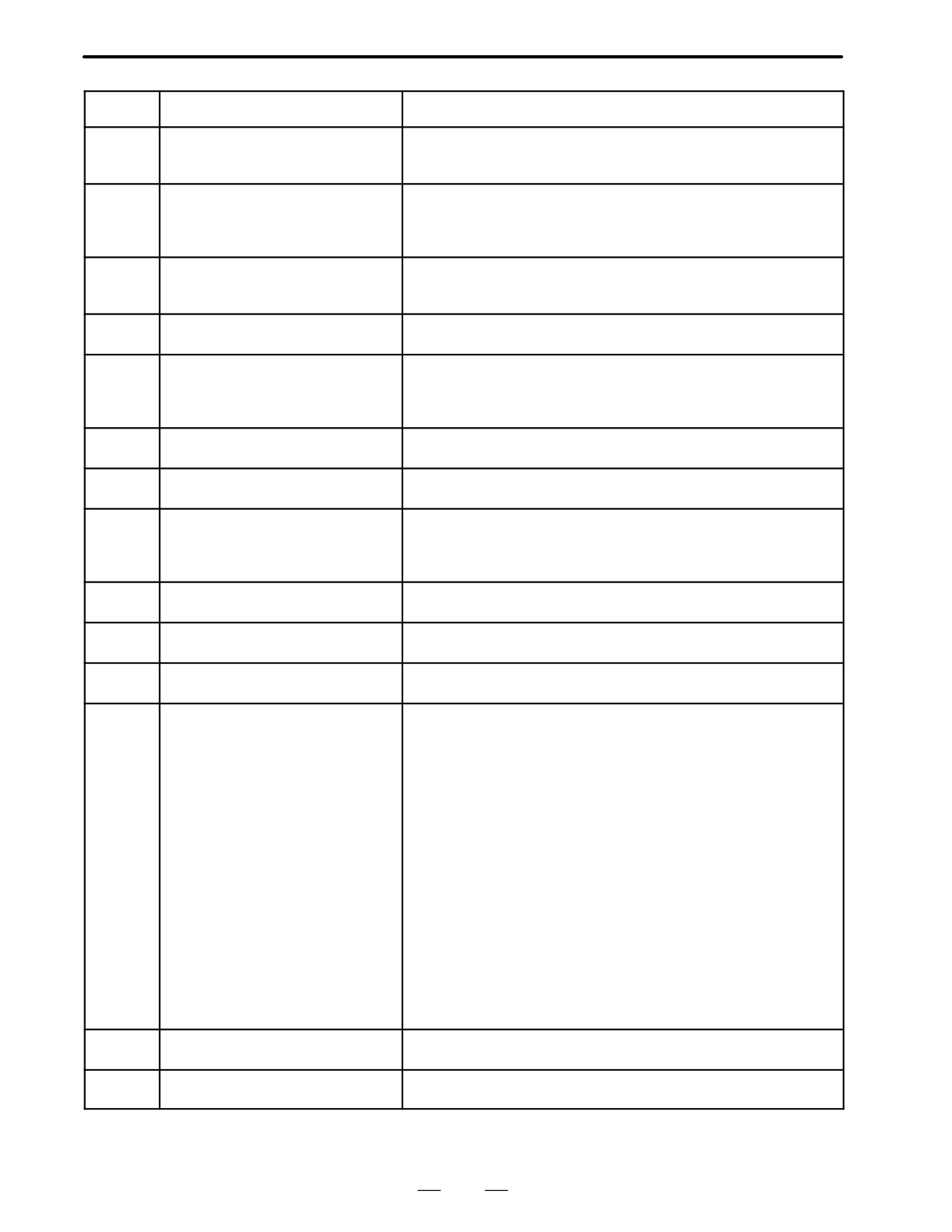
OFFSET NUMBER NOT FOUND IN
Tool length automatic measurement (G37) was specified without a H
G37
code. (Automatic tool length measurement function) Modify the pro-
081
(M series)
gram.
OFFSET NUMBER NOT FOUND IN
Automatic tool compensation (G36, G37) was specified without a T
G37 (T series)
code. (Automatic tool compensation function) Modify the program.
H-CODE NOT ALLOWED IN G37
H code and automatic tool compensation (G37) were specified in the
(M series)
same block. (Automatic tool length measurement function) Modify the
program.
082
T-CODE NOT ALLOWED IN G37
T code and automatic tool compensation (G36, G37) were specified
(T series)
in the same block. (Automatic tool compensation function)
Modify the program.
ILLEGAL AXIS COMMAND IN G37
In automatic tool length measurement, an invalid axis was specified
(M series)
or the command is incremental. Modify the program.
083
ILLEGAL AXIS COMMAND IN G37
In automatic tool compensation (G36, G37), an invalid axis was spe-
(T series)
cified or the command is incremental. Modify the program.
085
COMMUNICATION ERROR
When entering data in the memory by using Reader / Puncher inter-
face, an overrun, parity or framing error was generated. The number
of bits of input data or setting of baud rate or specification No. of I/O
unit is incorrect.
086
DR SIGNAL OFF
When entering data in the memory by using Reader / Puncher inter-
face, the ready signal (DR) of reader / puncher was turned off.
Power supply of I/O unit is off or cable is not connected or a P.C.B. is
defective.
087
BUFFER OVERFLOW
When entering data in the memory by using Reader / Puncher inter-
face, though the read terminate command is specified, input is not
interrupted after 10 characters read. I/O unit or P.C.B. is defective.
088
LAN FILE TRANS ERROR
File data transfer via OSI-ETHERNET has been stopped due to a
(CHANNEL-1)
transfer error.
089
LAN FILE TRANS ERROR
File data transfer via OSI-ETHERNET has been stopped due to a
(CHANNEL-2)
transfer error.
090
REFERENCE RETURN INCOM-
The reference position return cannot be performed normally because
PLETE
the reference position return start point is too close to the reference
position or the speed is too slow. Separate the start point far enough
from the reference position, or specify a sufficiently fast speed for
reference position return. Check the program contents.
091
REFERENCE RETURN INCOM-
Manual reference position return cannot be performed when auto-
PLETE
matic operation is halted.
092
AXES NOT ON THE REFERENCE
The commanded axis by G27 (Reference position return check) did
POINT
not return to the reference position.
094
P TYPE NOT ALLOWED (COORD
P type cannot be specified when the program is restarted. (After the
CHG)
automatic operation was interrupted, the coordinate system setting
operation was performed.)
Perform the correct operation according to th operator’s manual.
095
P TYPE NOT ALLOWED (EXT OFS
P type cannot be specified when the program is restarted.
(After the
CHG)
automatic operation was interrupted, the external workpiece offset
amount changed.)
Perform the correct operation according to th operator’s manual.
096
P TYPE NOT ALLOWED (WRK OFS
P type cannot be specified when the program is restarted. (After the
CHG)
automatic operation was interrupted, the workpiece offset amount
changed.)
Perform the correct operation according to the operator’s manual.
437
B. ALARM LIST
APPENDIX
B-62445E/03
Number
Message
Contents
097
P TYPE NOT ALLOWED (AUTO
P type cannot be directed when the program is restarted. (After pow-
EXEC)
er ON, after emergency stop or P / S 94 to 97 reset, no automatic
operation is performed.) Perform automatic operation.
098
G28 FOUND IN SEQUENCE RE-
A command of the program restart was specified without the refer-
TURN
ence position return operation after power ON or emergency stop,
and G28 was found during search.
Perform the reference position return.
099
MDI EXEC NOT ALLOWED AFT.
After completion of search in program restart, a move command is
SEARCH
given with MDI. Move axis before a move command or don’t interrupt
MDI operation.
100
PARAMETER WRITE ENABLE
On the PARAMETER(SETTING) screen, PWE(parameter writing en-
abled) is set to 1. Set it to 0, then reset the system.
101
PLEASE CLEAR MEMORY
The power turned off while rewriting the memory by program edit op-
eration. If this alarm has occurred, press <RESET> while pressing
<PROG>, and only the program being edited will be deleted.
Register the deleted program.
109
P/S ALARM
A value other than 0 or 1 was specified after P in the G08 code, or no
value was specified.
110
DATA OVERFLOW
The absolute value of fixed decimal point display data exceeds the
allowable range. Modify the program.
111
CALCULATED DATA OVERFLOW
The result of calculation turns out to be invalid, an alarm No.111 is
issued.
-1047 to -10-29, 0, 10-29 to 1047
Modify the program.
112
DIVIDED BY ZERO
Division by zero was specified. (including tan 90°)
Modify the program.
113
IMPROPER COMMAND
A function which cannot be used in custom macro is commanded.
Modify the program.
114
FORMAT ERROR IN MACRO
There is an error in other formats than <Formula>.
Modify the program.
115
ILLEGAL VARIABLE NUMBER
A value not defined as a variable number is designated in the custom
macro or in high-speed cycle machining.
The header contents are improper. This alarm is given in the follow-
ing cases:
High speed cycle machining
1. The header corresponding to the specified machining cycle
number called is not found.
2. The cycle connection data value is out of the allowable
range
(0 - 999).
3. The number of data in the header is out of the allowable
range
(0 - 32767).
4. The start data variable number of executable format data is
out of the allowable range (#20000 - #85535).
5. The last storing data variable number of executable format
data is out of the allowable range (#85535).
6. The storing start data variable number of executable format
data is overlapped with the variable number used in the
header.
Modify the program.
116
WRITE PROTECTED VARIABLE
The left side of substitution statement is a variable whose substitution
is inhibited. Modify the program.
118
PARENTHESIS NESTING ERROR
The nesting of bracket exceeds the upper limit (quintuple).
Modify the program.
438
B-62445E/03
APPENDIX
B. ALARM LIST
Number
Message
Contents
119
ILLEGAL ARGUMENT
The SQRT argument is negative. Or BCD argument is negative, and
other values than 0 to 9 are present on each line of BIN argument.
Modify the program.
122
FOUR FOLD MACRO MODAL-
The macro modal call is specified four fold.
CALL
Modify the program.
123
CAN NOT USE MACRO COMMAND
Macro control command is used during DNC operation.
IN DNC
Modify the program.
124
MISSING END STATEMENT
DO - END does not correspond to 1 : 1. Modify the program.
125
FORMAT ERROR IN MACRO
<Formula> format is erroneous. Modify the program.
126
ILLEGAL LOOP NUMBER
In DOn, 1x n x3 is not established. Modify the program.
127
NC, MACRO STATEMENT IN SAME
NC and custom macro commands coexist.
BLOCK
Modify the program.
128
ILLEGAL MACRO SEQUENCE
The sequence number specified in the branch command was not 0 to
NUMBER
9999. Or, it cannot be searched. Modify the program.
129
ILLEGAL ARGUMENT ADDRESS
An address which is not allowed in <Argument Designation > is used.
Modify the program.
130
ILLEGAL AXIS OPERATION
An axis control command was given by PMC to an axis controlled by
CNC. Or an axis control command was given by CNC to an axis
controlled by PMC. Modify the program.
131
TOO MANY EXTERNAL ALARM
Five or more alarms have generated in external alarm message.
MESSAGES
Consult the PMC ladder diagram to find the cause.
132
ALARM NUMBER NOT FOUND
No alarm No. concerned exists in external alarm message clear.
Check the PMC ladder diagram.
133
ILLEGAL DATA IN EXT. ALARM
Small section data is erroneous in external alarm message or exter-
MSG
nal operator message. Check the PMC ladder diagram.
ILLEGAL ANGLE COMMAND
The index table indexing positioning angle was instructed in other
(M series)
than an integral multiple of the value of the minimum angle.
Modify the program.
135
SPINDLE ORIENTATION PLEASE
Without any spindle orientation , an attept was made for spindle in-
(T series)
dexing. Perform spindle orientation.
ILLEGAL AXIS COMMAND
In index table indexing.Another control axis was instructed together
(M series)
with the B axis.
Modify the program.
136
C/H-CODE & MOVE CMD IN SAME
A move command of other axes was specified to the same block as
BLK. (T series)
spindle indexing addresses C, H. Modify the program.
137
M-CODE & MOVE CMD IN SAME
A move command of other axes was specified to the same block as
BLK.
M-code related to spindle indexing. Modify the program.
138
SUPERIMPOSED DATA OVER-
The total distribution amount of the CNC and PMC is too large during
FLOW
superimposed control of the extended functions for PMC axis control.
139
CAN NOT CHANGE PMC CON-
An axis is selected in commanding by PMC axis control.
TROL AXIS
Modify the program.
141
CAN NOT COMMAND G51 IN CRC
G51 (Scaling ON) is commanded in the tool offset mode.
(M series)
Modify the program.
142
ILLEGAL SCALE RATE
Scaling magnification is commanded in other than 1 - 999999.
(M series)
Correct the scaling magnification setting (G51 Pp
or parameter 5411 or 5421).
143
SCALED MOTION DATA OVER-
The scaling results, move distance, coordinate value and circular
FLOW
radius exceed the maximum command value. Correct the program or
(M series)
scaling mangification.
144
ILLEGAL PLANE SELECTED
The coordinate rotation plane and arc or cutter compensation C
(M series)
plane must be the same. Modify the program.
439
B. ALARM LIST
APPENDIX
B-62445E/03
Number
Message
Contents
145
ILLEGAL CONDITIONS IN POLAR
The conditions are incorrect when the polar coordinate interpolation
COORDINATE INTERPOLATION
starts or it is canceled.
1) In modes other than G40, G12.1/G13.1 was specified.
2) An error is found in the plane selection. Parameters No. 5460
and No. 5461 are incorrectly specified.
Modify the value of program or parameter.
146
IMPROPER G CODE
G codes which cannot be specified in the polar coordinate interpola-
tion mode was specified. See section II-4.4 and modify the program.
148
ILLEGAL SETTING DATA
Automatic corner override deceleration rate is out of the settable
(M series)
range of judgement angle. Modify the parameters (No.1710 to
No.1714)
149
FORMAT ERROR IN G10L3
A code other than Q1,Q2,P1 or P2 was specified as the life count
(M series)
type in the extended tool life management.
150
ILLEGAL TOOL GROUP NUMBER
Tool Group No. exceeds the maximum allowable value.
Modify the program.
151
TOOL GROUP NUMBER NOT
The tool group commanded in the machining program is not set.
FOUND
Modify the value of program or parameter.
152
NO SPACE FOR TOOL ENTRY
The number of tools within one group exceeds the maximum value
registerable. Modify the number of tools.
153
T-CODE NOT FOUND
In tool life data registration, a T code was not specified where one
should be. Correct the program.
154
NOT USING TOOL IN LIFE GROUP
When the group is not commanded, H99 or D99 was commanded.
(M series)
Correct the program.
155
ILLEGAL T-CODE IN M06
In the machining program, M06 and T code in the same block do not
(M series)
correspond to the group in use. Correct the program.
ILLEGAL T-CODE IN M06
Group No.ΔΔ which is specified with TΔΔ 88 of the machining pro-
(T series)
gram do not included in the tool group in use. Correct the program.
156
P/L COMMAND NOT FOUND
P and L commands are missing at the head of program in which the
tool group is set. Correct the program.
157
TOO MANY TOOL GROUPS
The number of tool groups to be set exceeds the maximum allowable
value. (See parameter No. 6800 bit 0 and 1) Modify the program.
158
ILLEGAL TOOL LIFE DATA
The tool life to be set is too excessive. Modify the setting value.
159
TOOL DATA SETTING INCOM-
During executing a life data setting program, power was turned off.
PLETE
Set again.
MISMATCH WATING M-CODE
Diffrent M code is commanded in heads 1 and 2 as waiting M code.
T series (At two-path)
Modify the program.
160
G72.1 NESTING ERROR
A subprogram which performs rotational copy with G72.1 contains
(M series)
another G72.1 command.
161
G72.1 NESTING ERROR
A subprogram which performs parallel copy with G72.2 contains
(M series)
another G72.2 command.
COMMAND G68/G69 INDEPEN-
G68 and G69 are not independently commanded in balance cut.
163
DENTLY T series (At two-path)
Modify the program.
169
ILLEGAL TOOL GEOMETRY DATA
Incorrect tool figure data in interference check.
T series (At two-path)
Set correct data, or select correct tool figure data.
175
ILLEGAL G107 COMMAND
Conditions when performing circular interpolation start or cancel not
correct. To change the mode to the cylindrical interpolation mode,
specify the command in a format of “G07.1 rotation-axis name radius
of cylinder.”
440
B-62445E/03
APPENDIX
B. ALARM LIST
Number
Message
Contents
IMPROPER G-CODE IN G107
Any of the following G codes which cannot be specified in the cylin-
(M series)
drical interpolation mode was specified.
1) G codes for positioning: G28,, G73, G74, G76, G81 - G89,
including the codes specifying the rapid traverse cycle
2) G codes for setting a coordinate system: G52,G92,
3) G code for selecting coordinate system: G53 G54-G59
Modify the program.
176
IMPROPER G-CODE IN G107
Any of the following G codes which cannot be specified in the cylin-
(T series)
drical interpolation mode was specified.
1) G codes for positioning: G28, G76, G81 - G89, including the
codes specifying the rapid traverse cycle
2) G codes for setting a coordinate system: G50, G52
3) G code for selecting coordinate system: G53 G54-G59
Modify the program.
177
CHECK SUM ERROR
Check sum error
(G05 MODE)
Modify the program.
178
G05 COMMANDED IN G41/G42
G05 was commanded in the G41/G42 mode.
MODE
Correct the program.
179
PARAM. (NO. 7510) SETTING ER-
The number of controlled axes set by the parameter 7510 exceeds
ROR
the maximum number. Modify the parameter setting value.
180
COMMUNICATION ERROR
Remote buffer connection alarm has generated. Confirm the number
(REMOTE BUF)
of cables, parameters and I/O device.
181
FORMAT ERROR IN G81 BLOCK
G81 block format error (hobbing machine)
(M series)
1) T (number of teeth) has not been instructed.
2) Data outside the command range was instructed by either T, L,
Q or P.
Modify the program.
182
G81 NOT COMMANDED
G83 (C axis servo lag quantity offset) was instructed though synchro-
(M series)
nization by G81 has not been instructed. Correct the program. (hob-
bing machine)
183
DUPLICATE G83 (COMMANDS)
G83 was instructed before canceled by G82 after compensating for
(M series)
the C axis servo lag quantity by G83. (hobbing machine)
184
ILLEGAL COMMAND IN G81
A command not to be instructed during synchronization by G81 was
(M series)
instructed.
(hobbing machine)
1) A C axis command by G00, G27, G28, G29, G30, etc. was
instructed.
2) Inch/Metric switching by G20, G21 was instructed.
185
RETURN TO REFERENCE POINT
G81 was instructed without performing reference position return after
(M series)
power on or emergency stop. (hobbing machine) Perform reference
position return.
186
PARAMETER SETTING ERROR
Parameter error regarding G81 (hobbing machine)
(M series)
1) The C axis has not been set to be a rotary axis.
2) A hob axis and position coder gear ratio setting error
Modify the parameter.
190
ILLEGAL AXIS SELECT
In the constant surface speed control, the axis specification is wrong.
(M series)
(See parameter No. 3770.) The specified axis command (P) contains
an illegal value.
Correct the program.
194
SPINDLE COMMAND IN SYN-
A contour control mode, spindle positioning (Cs-axis control) mode,
CHRO-MODE
or rigid tapping mode was specified during the serial spindle
synchronous control mode. Correct the program so that the serial
spindle synchronous control mode is released in advance.
441
B. ALARM LIST
APPENDIX
B-62445E/03
Number
Message
Contents
195
MODE CHANGE ERROR
Switching command to contouring mode, Cs axis control or rigid tap
mode or switching to spindle command mode is not correctly com-
pleted.
(This occurs when the response to switch to the spindle control unit
side with regard to the switching command from the NC is incorrect.
This alarm is not for the purposes of warning against mistakes in op-
eration, but because continuing operation in this condition can be
dangerous it is a P/S alarm.)
197
C-AXIS COMMANDED IN SPINDLE
The program specified a movement along the Cs-axis when the sig-
MODE
nal CON(DGN=G027#7) was off. Correct the program, or consult the
PMC ladder diagram to find the reason the signal is not turned on.
199
MACRO WORD UNDEFINED
Undefined macro word was used. Modify the custom macro.
200
ILLEGAL S CODE COMMAND
In the rigid tap, an S value is out of the range or is not specified.
Modify the program.
201
FEEDRATE NOT FOUND IN RIGID
In the rigid tap, no F value is specified.
TAP
Correct the program.
202
POSITION LSI OVERFLOW
In the rigid tap, spindle distribution value is too large. (System error)
203
PROGRAM MISS AT RIGID TAP-
In the rigid tap, position for a rigid M code (M29) or an S command is
PING
incorrect. Modify the program.
204
ILLEGAL AXIS OPERATION
In the rigid tap, an axis movement is specified between the rigid M
code (M29) block and G84 or G74 for M series (G84 or G88 for T
series) block. Modify the program.
205
RIGID MODE DI SIGNAL OFF
Rigid mode DI signal is not ON when G84 or G74 for M series (G84
or G88 for T series) is executed though the rigid M code (M29) is
specified.Consult the PMC ladder diagram to find the reason the DI
signal (DGNG061.1) is not turned on.
206
CAN NOT CHANGE PLANE (RIGID
Plane changeover was instructed in the rigid mode.
TAP) (M series)
Correct the program.
210
CAN NOT COMAND M198/M199
M198 and M199 are executed in the schedule operation. M198 is
executed in the DNC operation. Modify the program.
1) The execution of an M198 or M99 command was attempted during
scheduled operation. Alternatively, the execution of an M198
command was attempted during DNC operation. Correct the pro-
gram.
2) The execution of an M99 command was attempted by an interrupt
macro during pocket machining in a multiple repetitive canned
cycle.
211
G31 (HIGH) NOT ALLOWED IN G99
G31 is commanded in the per revolution command when the high-
speed skip option is provided. Modify the program.
ILLEGAL PLANE SELECT
The arbitrary angle chamfering or a corner R is commanded or the
(M series)
plane including an additional axis. Correct the program.
212
ILLEGAL PLANE SELECT
The direct drawing dimensions programming is commanded for the
(T series)
plane other than the Z-X plane. Correct the program.
442
B-62445E/03
APPENDIX
B. ALARM LIST
Number
Message
Contents
213
ILLEGAL COMMAND IN SYN-
Movement is commanded for the axis to be synchronously controlled.
CHRO-MODE
Any of the following alarms occurred in the operation with the simple
synchronization control.
1) The program issued the move command to the slave axis.
2) The program issued the manual continuous feed/manual handle
feed/incremental feed command to the slave axis.
3) The program issued the automatic reference position return
command without specifying the manual reference position return
after the power was turned on.
4) The difference between the position error amount of the master
and slave axes exceeded the value specified in parameter
NO.8313.
ILLEGAL COMMAND IN SYN-
A move command has been specified for an axis subject to synchro-
CHRO-MODE
nous control.
(T series)
214
ILLEGAL COMMAND IN SYN-
Coordinate system is set or tool compensation of the shift type is
CHRO-MODE
executed in the synchronous control. Correct the program.
217
DUPLICATE G51.2 (COMMANDS)
G51.2/G251 is further commanded in the G51.2/G251 mode. Modify
(T series)
the program.
218
NOT FOUND P/Q COMMAND IN
P or Q is not commanded in the G251 block, or the command value
G251 (T series)
is out of the range. Modify the program.
219
COMMAND G250/G251 INDEPEN-
G251 and G250 are not independent blocks.
DENTLY (T series)
220
ILLEGAL COMMAND IN SYNCHR-
In the synchronous operation, movement is commanded by the NC
MODE (T series)
program or PMC axis control interface for the synchronous axis.
221
ILLEGAL COMMAND IN SYNCHR-
Polygon machining synchronous operation and axis control or bal-
MODE (T series)
ance cutting are executed at a time. Modify the program.
222
DNC OP. NOT ALLOWED IN BG.-
Input and output are executed at a time in the background edition.
EDIT (M series)
Execute a correct operation.
RETURN TO REFERENCE POINT
Reference position return has not been performed before the auto-
(M series)
matic operation starts. Perform reference position return only when
224
bit 0 of parameter 1005 is 0.
TURN TO REFERENCE POINT
Reference position return is necessary before cycle start.
(T series)
225
SYNCHRONOUS/MIXED CONTROL
This alarm is generated in the following circumstances. (Searched for
ERROR
during synchronous and mixed control command.
T series (At two-path)
1
When there is a mistake in axis number parameter setting.
2
When there is a mistake in control commanded.
Modify the program or the parameter.
226
ILLEGAL COMMAND IN SYNCHRO-
A travel command has been sent to the axis being synchronized in
MODE T series (At two-path)
synchronous mode. Modify the program or the parameter.
229
CAN NOT KEEP SYNCHRO-STATE
This alarm is generated in the following circumstances.
1
When the synchro/mixed state could not be kept due to system
(T series)
overload.
2
The above condition occurred in CMC devices (hardware) and
synchro-state could not be kept.
(This alarm is not generated in normal use conditions.)
230
R CODE NOT FOUND
The infeed quantity R has not been instructed for the G161 block. Or
(GS series)
the R command value is negative. Correct the program.
443
B. ALARM LIST
APPENDIX
B-62445E/03
Number
Message
Contents
231
ILLEGAL FORMAT IN G10 OR L50
Any of the following errors occurred in the specified format at the pro-
grammable-parameter input.
1
Address N or R was not entered.
2
A number not specified for a parameter was entered.
3
The axis number was too large.
4
An axis number was not specified in the axis-type parameter.
5
An axis number was specified in the parameter which is not an
axis type. Correct the program.
6
An attempt was made to reset bit 4 of parameter 3202 (NE9) or
change parameter 3210 (PSSWD) when they are protected by a
password. Correct the program.
232
TOO MANY HELICAL AXIS COM-
Three or more axes (in the normal direction control mode two or more
MANDS (M series)
axes) were specified as helical axes in the helical interpolation mode.
233
DEVICE BUSY
When an attempt was made to use a unit such as that connected via
the RS-232-C interface, other users were using it.
239
BP/S ALARM
While punching was being performed with the function for controlling
external I/O units ,background editing was performed.
240
BP/S ALARM
Background editing was performed during MDI operation.
241
ILLEGAL FORMAT IN G02.2/G03.2
The end point, I, J, K, or R is missing from a command for involute
(M series)
interpolation.
242
ILLEGAL COMMAND IN
An invalid value has been specified for involute interpolation.
G02.2/G03.2
S The start or end point is within the basic circle.
(M series)
S I, J, K, or R is set to 0.
S The number of rotations between the start of the involute curve and
the start or end point exceeds 100.
243
OVER TOLERANCE OF END
The end point is not on the involute curve which includes the start
POINT
point and thus falls outside the range specified with parameter No.
(M series)
5610.
244
P/S ALARM
In the skip function activated by the torque limit signal, the number of
(T series)
accumulated erroneous pulses exceed 32767 before the signal was
input. Therefore, the pulses cannot be corrected with one distribution.
Change the conditions, such as feed rates along axes and torque
limit, and try again.
245
T-CODE NOT ALOWEE IN THIS
One of the G codes, G50, G10, and G04, which cannot be specified
BLOCK (T series)
in the same block as a T code, was specified with a T code.
250
Z AXIS WRONG COMMAND (ATC)
A value for the Z-axis has been specified in a block for the tool ex-
(M series)
change command (M06T_) on a system with DRILL-MATE ARC
installed.
251
ATC ERROR
This alarm is issued in the following cases (DRILL-MATE):
(M series)
S An M06T_ command contains an unusable T code.
S An M06 command has been specified when the Z machine coordi
nate is positive.
S The parameter for the current tool number (No. 7810) is set to 0.
S An M06 command has been specified in canned cycle mode.
S A reference position return command (G27 to G44) and M06 com
mand have been specified in the same block.
S An M06 command has been specified in tool compensation mode
(G41 to G44).
S An M06 command has been specified without performing reference
position return after power-on or the release of emergency stop.
S The machine lock signal or Z-axis ignore signal has been turned
on during tool exchange.
S A pry alarm has been detected during tool exchange.
Refer to diagnosis No. 530 to determine the cause.
444
B-62445E/03
APPENDIX
B. ALARM LIST
Number
Message
Contents
252
ATC SPINDLE ALARM
An excessive error arose during spindle positioning for ATC. For
(M series)
details, refer to diagnosis No. 531. (Only for DRILL-MATE)
253
G05 IS NOT AVAILABLE
Alarm details
(M series)
Binary input operation using high-speed remote buffer (G05) or high-
speed cycle machining (G05) has been specified in advance control
mode (G08P1). Execute G08P0; to cancel advance control mode,
before executing these G05 commands.
5000
ILLEGAL COMMAND CODE
The specified code was incorrect in the high-precision contour con-
(M series)
trol (HPCC) mode.
5003
ILLEGAL PARAMETER (HPCC)
There is an invalid parameter.
(M series)
5004
HPCC NOT READY (M series)
High-precision contour control is not ready.
5006
TOO MANY WORD IN ONE BLOCK
The number of words specified in a block exceeded 26 in the HPCC
(M series)
mode.
5007
TOO LARGE DISTANCE (M series)
In the HPCC mode, the machine moved beyond the limit.
5009
PARAMETER ZERO (DRY RUN)
The maximum feedrate (parameter No. 1422) or the feedrate in dry
(M series)
run (parameter No. 1410) is 0 in the HPCC model.
5010
END OF RECORD
The end of record (%) was specified.
I/O is incorrect. modify the program.
5011
PARAMETER ZERO(CUT MAX)
The maximum cutting feedrate (parameter No. 1422)is 0 in the HPCC
(M series)
mode.
5012
G05 P10000 ILLEGAL START UP
Function category:
(HPCC)
High-precision contour control
(M series)
Alarm details:
G05 P10000 has been specified in a mode from which the system
cannot enter HPCC mode.
5013
HPCC: CRC OFS REMAIN AT CAN-
G05P0 has been specified in G41/G42 mode or with offset remaining.
CEL (M series)
5014
TRACE DATA NOT FOUND
Transfer cannot be performed because no trace data exists.
(M series)
5015
The specified rotation axis does not exist for tool axis direction han-
(M series)
dle feed.
5016
ILLEGAL COMBINATION OF M
M codes which belonged to the same group were specified in a
CODE
block. Alternatively,an M code which must be specified without other
M codes in the block was specified in a block with other M codes.
5018
POLYGON SPINDLE SPEED ER-
Function category:
ROR
Polygon turning
(T series)
Alarm details:
In G51.2 mode, the speed of the spindle or polygon synchronous
axis either exceeds the clamp value or is too small. The specified
rotation speed ratio thus cannot be maintained.
5020
PARAMETER OF RESTART ER-
An erroneous parameter was specified for restarting a program.
ROR
A parameter for program restart is invalid.
5030
ILLEGAL COMMAND (G100)
The end command (G110) was specified before the registratioin start
(T series)
command (G101, G102, or G103) was specified for the B-axis.
5031
ILLEGAL COMMAND (G100, G102,
While a registration start command (G101, G102, or G103) was being
G103) (T series)
executed, another registration start command was specified for the
B-axis.
5032
NEW PRG REGISTERED IN B-AXS
While the machine was moving about the B-axis, at attempt was
MOVE (T series)
made to register another move command.
5033
NO PROG SPACE IN MEMORY B-
Commands for movement about the B-axis were not registered be-
AXS (T series)
cause of insufficient program memory.
445
B. ALARM LIST
APPENDIX
B-62445E/03
Number
Message
Contents
5034
PLURAL COMMAND IN G110
Multiple movements were specified with the G110 code for the B-
(T series)
axis.
5035
NO FEEDRATE COMMANDED B-
A feedrate was not specified for cutting feed about the B-axis.
AXS (T series)
5036
ADDRESS R NOT DEFINED IN
Point R was not specified for the canned cycle for the B-axis.
G81-G86 (T series)
5037
ADDRESS Q NOT DEFINED IN G83
Depth of cut Q was not specified for the G83 code (peck drilling
(T series)
cycle). Alternatively, 0 was specified in Q for the B-axis.
5038
TOO MANY START M-CODE COM-
More than six M codes for starting movement about the B-axis were
MAND (T series)
specified.
5039
START UNREGISTERED B-AXS
An attempt was made to execute a program for the B-axis which had
PROG (T series)
not been registered.
5040
CAN NOT COMMANDED B-AXS
The machine could not move about the B-axis because parameter
MOVE (T series)
No.8250 was incorrectly specified, or because the PMC axis system
could not be used.
5041
CAN NOT COMMANDED G110
Blocks containing the G110 codes were successively specified in
BLOCK (T series)
tool-tip radius compensation for the B-axis.
5043
TOO MANY G68 NESTING
Three-dimensional coordinate conversion G68 has been specified
(M series)
three or more times.
5044
G68 FORMAT ERROR
A G68 command block contains a format error. This alarm is issued
(M series)
in the following cases:
1. I, J, or K is missing from a G68 command block (missing coordi
nate rotation option).
2. I, J, and K are 0 in a G68 command block.
3. R is missing from a G68 command block.
5046
ILLEGAL PARAMETER (ST.COMP)
The parameter settings for straightness compensation contain an
error. Possible causes are as follows:
1. A parameter for a movement axis or compensation axis contains
an axis number which is not used.
2. More than 128 pitch error compensation points exist between the
negative and positive end points.
3. Compensation point numbers for straightness compensation are
not assigned in the correct order.
4. No straightness compensation point exists between the pitch error
compensation points at the negative and positive ends.
5. The compensation value for each compensation point is too large
or too small.
5050
ILL-COMMAND IN CHOPPING
A command for switching the major axis has been specified for circu-
MODE
lar threading. Alternatively, a command for setting the length of the
(M series)
major axis to 0 has been specified for circular threading.
5051
M-NET CODE ERROR
Abnormal character received (other than code used for transmission)
5052
M-NET ETX ERROR
Abnormal ETX code
5053
M-NET CONNECT ERROR
Connection time monitoring error (parameter No. 175)
5054
M-NET RECEIVE ERROR
Polling time monitoring error (parameter No. 176)
5055
M-NET PRT/FRT ERROR
Vertical parity or framing error
5057
M-NET BOARD SYSTEM DOWN
Transmission timeout error (parameter No. 177)
ROM parity error
CPU interrupt other than the above
5058
G35/G36 FORMAT ERROR
A command for switching the major axis has been specified for circu-
(T series)
lar threading. Alternatively, a command for setting the length of the
major axis to 0 has been specified for circular threading.
5059
RADIUS IS OUT OF RANGE
A radius exceeding nine digits has been specified for circular inter-
(T series)
polation with the center of the arc specified with I, J, and K.
446
B-62445E/03
APPENDIX
B. ALARM LIST
Number
Message
Contents
5063
IS NOT PRESET AFTER REF.
Function category:
(M series)
Workpiece thickness measurement
Alarm details
The position counter was not preset before the start of workpiece
thickness measurement. This alarm is issued in the following cases:
(1) An attempt has been made to start measurement without first
establishing the origin.
(2) An attempt has been made to start measurement without first
presetting the position counter after manual return to the origin.
5064
DIFFERRENT AXIS UNIT (IS-B,
Circular interpolation has been specified on a plane consisting of
IS-C)
axes having different increment systems.
(M series)
5065
DIFFERENT AXIS UNIT (PMC AXIS)
Axes having different increment systems have been specified in the
(M series)
same DI/DO group for PMC axis control. Modify the setting of param-
eter No. 8010.
5066
RESTART ILLEGAL SEQUENCE
Sequence number 7xxx has been read during search for the next
NUMBER
sequence number at program restart for the return/restart function.
(M series)
5068
G31 P90 FORMAT ERROR
No movement axis or more than one movement axis has been speci-
(M series)
fied.
5073
NO DECIMAL POINT
No decimal point has been specified for an address requiring a deci-
mal point.
5074
ADDRESS DUPLICATION ERROR
The same address has been specified two or more times in a single
block. Alternatively, two or more G codes in the same group have
been specified in a single block.
5082
DATA SERVER ERROR
This alarm is detailed on the data server message screen.
Note
HPCC : High precision contour control
447
B. ALARM LIST
APPENDIX
B-62445E/03
(2) Background edit alarm
Number
Message
Contents
???
BP/S alarm
BP/S alarm occurs in the same number as the P/S alarm that occurs in
ordinary program edit. (070, 071, 072, 073, 074 085,086,087 etc.)
140
BP/S alarm
It was attempted to select or delete in the background a program being
selected in the foreground. (Note)
Use background editing correctly.
Note
Alarm in background edit is displayed in the key input line of the background edit screen instead
of the ordinary alarm screen and is resettable by any of the MDI key operation.
(3) Absolute pulse coder (APC) alarm
Number
Message
Contents
300
nth-axis origin return
Manual reference position return is required for the nth-axis (n=1 - 8).
301
APC alarm: nth-axis communication
nth-axis (n=1 - 8) APC communication error. Failure in data transmis-
sion
Possible causes include a faulty APC, cable, or servo interface module.
302
APC alarm: nth-axis over time
nth-axis (n=1 - 8) APC overtime error.
Failure in data transmission.
Possible causes include a faulty APC, cable, or servo interface module.
303
APC alarm: nth-axis framing
nth-axis (n=1 - 8) APC framing error. Failure in data transmission.
Possible causes include a faulty APC, cable, or servo interface module.
304
APC alarm: nth-axis parity
nth-axis (n=1 - 8) APC parity error.
Failure in data transmission.
Possible causes include a faulty APC, cable, or servo interface module.
305
APC alarm: nth-axis pulse error
nth-axis (n=1 - 8) APC pulse error alarm.
APC alarm.APC or cable may be faulty.
306
APC alarm: nth-axis battery
nth-axis (n=1 - 8) APC battery voltage has decreased to a low level so
voltage 0
that the data cannot be held.
APC alarm. Battery or cable may be faulty.
307
APC alarm: nth-axis battery low 1
nth-axis (n=1 - 8) axis APC battery voltage reaches a level where the
battery must be renewed.
APC alarm. Replace the battery.
308
APC alarm: nth-axis battery low 2
nth-axis (n=1 - 8) APC battery voltage has reached a level where the
battery must be renewed (including when power is OFF).
APC alarm .Replace battery.
309
APC ALARM:
Return to the origin has been attempted without first rotating the motor
n AXIS ZRN IMPOSSIBL
one or more times. Before returning to the origin, rotate the motor one
or more times then turn off the power.
(4) Serial pulse coder
When either of the following alarms is issued, a possible cause is a faulty
(SPC) alarms
serial pulse coder or cable.
Number
Message
Contents
350
SPC ALARM: n AXIS PULSE COD-
The n axis (axis 1-8) pulse coder has a fault. Refer to diagnosis display
ER
No. 202 and No. 204 for details.
351
SPC ALARM: n AXIS COMMUNICA-
n axis (axis 1-8) serial pulse coder communication error (data transmis-
TION
sion fault)
Refer to diagnosis display No. 203 for details.
448
B-62445E/03
APPENDIX
B. ALARM LIST
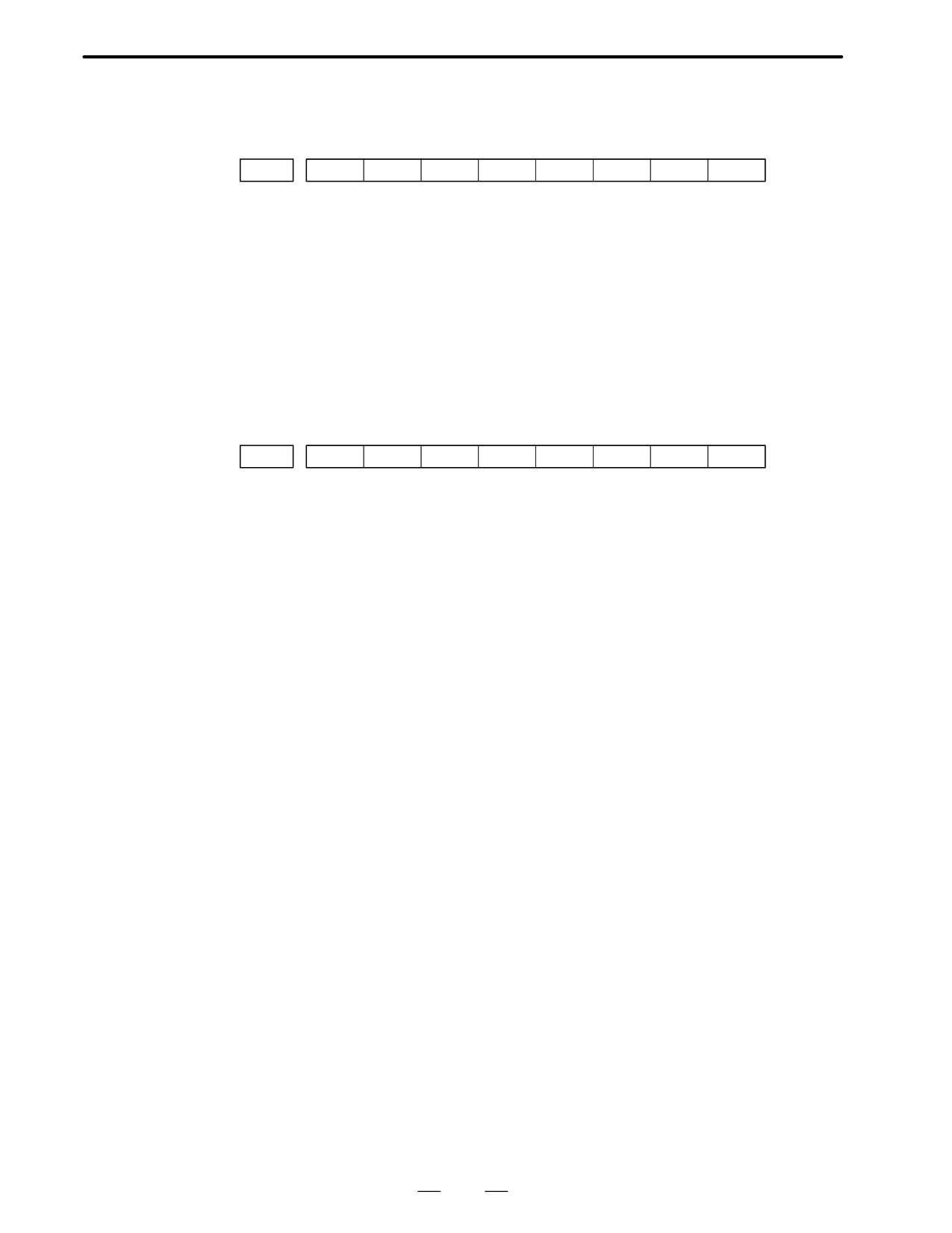
D The details of serial
pulse coder alarm
No.350
#7
#6
#5
#4
#3
#2
#1
#0
202
CSA
BLA
PHA
PCA
BZA
CKA
SPH
#6 (CSA) : Check sum alarm has occurred.
#5 (BLA) : Battery low alarm has occurred.
#4 (PHA) : Phase data trouble alarm has occurred.
#3 (PCA) : Speed count trouble alarm has occurred.
#2 (BZA) : Battery zero alarm has occurred.
#1 (CKA) : Clock alarm has occurred.
#0 (SPH) : Soft phase data trouble alarm has occurred.
D The details of serial
pulse coder alarm
No.351
#7
#6
#5
#4
#3
#2
#1
#0
203
DTE
CRC
STB
#7 (DTE) : Data error has occurred.
#6 (CRC) : CRC error has occurred.
#5 (STB) : Stop bit error has occurred.
449
B. ALARM LIST
APPENDIX
B-62445E/03
(5) Servo alarms
Number
Message
Contents
400
SERVO ALARM: n-TH AXIS OVER-
The n-th axis (axis 1-8) overload signal is on. Refer to diagnosis dis-
LOAD
play No. 201 for details.
401
SERVO ALARM: n-TH AXIS VRDY
The n-th axis (axis 1-8) servo amplifier READY signal (DRDY) went off.
OFF
Refer to procedure of trouble shooting.
404
SERVO ALARM: n-TH AXIS VRDY
Even though the n-th axis (axis 1-8) READY signal (MCON) went off,
ON
the servo amplifier READY signal (DRDY) is still on. Or, when the power
was turned on, DRDY went on even though MCON was off.
Check that the servo interface module and servo amp are connected.
405
SERVO ALARM: (ZERO POINT RE-
Position control system fault. Due to an NC or servo system fault in the
TURN FAULT)
reference position return, there is the possibility that reference position
return could not be executed correctly. Try again from the manual refer-
ence position return.
407
SERVO ALARM: EXCESS ERROR
The difference in synchronous axis position deviation exceeded the set
value.
409
SERVO ALARM: n AXIS TORQUE
Abnormal servo motor load has been detected. Alternatively, abnormal
ALM
spindle motor load has been detected in Cs mode.
410
SERVO ALARM: n-TH AXIS - EX-
The position deviation value when the n-th axis (axis 1-8) stops is larg-
CESS ERROR
er than the set value.
Refer to procedure of trouble shooting.
411
SERVO ALARM: n-TH AXIS - EX-
The position deviation value when the n-th axis (axis 1-8) moves is
CESS ERROR
larger than the set value.
Refer to procedure of trouble shooting.
413
SERVO ALARM: n-th AXIS - LSI
The contents of the error register for the n-th axis (axis 1-8) exceeded
OVERFLOW
"231 power. This error usually occurs as the result of an improperly set
parameters.
414
SERVO ALARM: n-TH AXIS -
N-th axis (axis 1-8) digital servo system fault. Refer to diagnosis dis-
DETECTION RELATED ERROR
play No. 200 and No.204 for details.
415
SERVO ALARM: n-TH AXIS - EX-
A speed higher than 511875 units/s was attempted to be set in the n-th
CESS SHIFT
axis (axis 1-8). This error occurs as the result of improperly set CMR.
416
SERVO ALARM: n-TH AXIS - DIS-
Position detection system fault in the n-th axis (axis 1-8) pulse coder
CONNECTION
(disconnection alarm). Refer to diagnosis display No. 201 for details.
417
SERVO ALARM: n-TH AXIS - PA-
This alarm occurs when the n-th axis (axis 1-8) is in one of the condi-
RAMETER INCORRECT
tions listed below.
(Digital servo system alarm)
1) The value set in Parameter No. 2020 (motor form) is out of the
specified limit.
2) A proper value (111 or -111) is not set in parameter No.2022
(motor revolution direction).
3) Illegal data (a value below 0, etc.) was set in parameter No. 2023
(number of speed feedback pulses per motor revolution).
4) Illegal data (a value below 0, etc.) was set in parameter No. 2024
(number of position feedback pulses per motor revolution).
5) Parameters No. 2084 and No. 2085 (flexible field gear rate) have
not been set.
6) A value outside the limit of {1 to the number of control axes} or
a non-continuous value (Parameter 1023 (servo axis number) con
tains a value out of the range from 1 to the number of axes, or an
isolated value (for example, 4 not prceded by 3).was set in parame
ter No. 1023 (servo axisnumber).
450
B-62445E/03
APPENDIX
B. ALARM LIST
Number
Message
Contents
420
SERVO ALARM: n AXIS SYNC
During simple synchronous control, the difference between the torque
TORQUE
commands for the master and slave axes exceeded the value set in pa-
(M series)
rameter No. 2031.
421
SERVO ALARM: n AXIS EXCESS
The difference between the errors in the semi-closed loop and closed
ER (D)
loop has become excessive during dual position feedback. Check the
values of the dual position conversion coefficients in parameters No.
2078 and 2079.
D Details of servo
The details of servo alarm No. 414 are displayed in the diagnosis display
alarm No.414
(No. 200 and No.204) as shown below.
#7
#6
#5
#4
#3
#2
#1
#0
200
OVL
LV
OVC
HCA
HVA
DCA
FBA
OFA
#7 (OVL) : An overload alarm is being generated.
#6 (LV) : A low voltage alarm is being generated in servo amp.
#5 (OVC) : A overcurrent alarm is being generated inside of digital servo.
#4 (HCA) : An abnormal current alarm is being generated in servo amp.
#3 (HVA) : An overvoltage alarm is being generated in servo amp.
#2 (DCA) : A regenerative discharge circuit alarm is being generated in servo amp.
#1 (FBA) : A disconnection alarm is being generated.
#0 (OFA) : An overflow alarm is being generated inside of digital servo.
#7
#6
#5
#4
#3
#2
#1
#0
204
OFS
MCC
LDA
PMS
#6 (OFS) : A current conversion error has occured in the digital servo.
#5 (MCC) : A magnetic contactor contact in the servo amplifier has welded.
#4 (LDA) : The LED indicates that serial pulse coder C is defective
#3 (PMS) : A feedback pulse error has occured because the feedback cable is
defective.
D Details of servo
The details of servo alarms No. 400 and No. 416 are displayed in the
alarms No. 400 and
diagnosis display (No. 201) as shown below.
No.416
#7
#6
#5
#4
#3
#2
#1
#0
201
ALD
EXP
When OVL equal 1 in diagnostic data No.200 (servo alarm No. 400 is
being generated):
#7 (ALD)
0 : Motor overheating
1 : Amplifier overheating
When FBAL equal 1 in diagnostic data No.200 (servo alarm No. 416 is
being generated):
ALD
EXP
Alarm details
1
0
Built-in pulse coder disconnection (hardware)
1
1
Separately installed pulse coder disconnection
(hardware)
0
0
Pulse coder is not connected due to software.
451
B. ALARM LIST
APPENDIX
B-62445E/03
(6) Over travel alarms
Number
Message
Contents
500
OVER TRAVEL : +n
Exceeded the n-th axis (axis 1-8) + side stored stroke limit I.
(Parameter No.1320 or 1326 Notes)
501
OVER TRAVEL : -n
Exceeded the n-th axis (axis 1-8) - side stored stroke limit I.
(Parameter No.1321 or 1327 Notes)
502
OVER TRAVEL : +n
Exceeded the n-th axis (axis 1-8) + side stored stroke limit II.
(Parameter No.1322 )
503
OVER TRAVEL : -n
Exceeded the n-th axis (axis 1-8) - side stored stroke limit II.
(Parameter No.1323)
504
OVER TRAVEL : +n
Exceeded the n-th axis (axis 1-8) + side stored stroke limit III.
(Parameter No.1324 )
505
OVER TRAVEL : -n
Exceeded the n-th axis (axis 1-8) - side stored stroke limit III.
(Parameter No.1325 )
506
OVER TRAVEL : +n
Exceeded the n-th axis (axis 1-8) + side hardware OT.
507
OVER TRAVEL : -n
Exceeded the n-th axis (axis 1-8) - side hardware OT.
508
INTERFERENCE: +n
A tool moving in the positive direction along the n axis has fouled anoth-
(T series (two-path control))
er tool post.
509
INTERFERENCE: -n
A tool moving in the negative direction along the n axis has fouled anoth-
(T series (two-path control))
er tool post.
510
OVER TRAVEL: +n
Alarm for stroke check prior to movement. The end point specified in a
block falls within the forbidden area defined with the stroke limit in the
positive direction along the N axis. Correct the program.
511
OVER TRAVEL: -n
Alarm for stroke check prior to movement. The end point specified in a
block falls within the forbidden area defined with the stroke limit in the
negative direction along the N axis. Correct the program.
Note
Parameters 1326 and 1327 are effective when EXLM(stroke limit switch signal) is on.
(7) Overheat alarms
Number
Message
Contents
700
OVERHEAT: CONTROL UNIT
Control unit overheat
Check that the fan motor operates normally, and clean the air filter.
701
OVERHEAT: FAN MOTOR
The fan motor on the top of the cabinet for the contorl unit is overheated.
Check the operation of the fan motor and replace the motor if necessary.
704
OVERHEAT: SPINDLE
Spindle overheat in the spindle fluctuation detection
(1)If the cutting load is heavy, relieve the cutting condition.
(2)Check whether the cutting tool is share.
(3)Another possible cause is a faulty spindle amp.
452
B-62445E/03
APPENDIX
B. ALARM LIST
(8) Rigid tapping alarms
Number
Message
Contents
740
RIGID TAP ALARM: EXCESS ER-
The positional deviation of the stopped spindle has exceeded the set
ROR
value during rigid tapping.
741
RIGID TAP ALARM: EXCESS ER-
The positional deviation of the moving spindle has exceeded the set val-
ROR
ue during rigid tapping.
742
RIGID TAP ALARM: LSI OVER-
An LSI overflow has occurred for the spindle during rigid tapping.
FLOW
(9) Serial spindle alarms
Number
Message
Contents
749
S-SPINDLE LSI ERROR
It is serial communication error while system is executing after power
supply on. Following reasons can be considered.
1) Optical cable connection is fault or cable is not connected or cable
is cut.
2) MAIN CPU board or option 2 board is fault.
3) Spindle amp. printed board is fault.
If this alarm occurs when CNC power supply is turned on or when
this alarm can not be cleared even if CNC is reset, turn off the
power supply also turn off the power supply in spindle side.
750
SPINDLE SERIAL LINK START
This alarm is generated when the spindle control unit is not ready for
FAULT
starting correctly when the power is turned on in the system with the
serial spindle.
The four reasons can be considered as follows:
1) An improperly connected optic cable, or the spindle control unit’s
power is OFF.
2) When the NC power was turned on under alarm conditions other
than SU-01 or AL-24 which are shown on the LED display of the
spindle control unit.
In this case, turn the spindle amplifier power off once and perform
startup again.
3) Other reasons (improper combination of hardware)
This alarm does not occur after the system including the spindle con-
trol unit is activated.
4) The second spindle (when SP2, bit 4 of parameter No. 3701, is 1)
is in one of the above conditions 1) to 3).
See diagnostic display No. 409 for details.
751
FIRST SPINDLE ALARM DETEC-
This alarm indicates in the NC that an alarm is generated in the spindle
TION (AL-XX)
unit of the system with the serial spindle. The alarm is displayed in form
AL-XX (XX is a number). Refer to 2.3 or 2.4 Alarms displayed on
spindle servo unit .The alarm number XX is the number indicated on
the spindle amplifier. The CNC holds this number and displays on the
screen.
752
FIRST SPINDLE MODE CHANGE
This alarm is generated if the system does not properly terminate a
FAULT
mode change. The modes include the Cs contouring, spindle position-
ing, rigid tapping, and spindle control modes. The alarm is activated if
the spindle control unit does not respond correctly to the mode change
command issued by the NC.
754
SPINDLE-1 ABNORMAL TORQUE
Abnormal first spindle motor load has been detected.
ALM
761
SECOND SPINDLE ALARM
Refer to alarm No. 751. (For 2nd axis)
DETECTION (AL-XX)
762
SECOND SPINDLE MODE
Refer to alarm No. 752.(For 2nd axis)
CHANGE FAULT
453
B. ALARM LIST
APPENDIX
B-62445E/03
Number
Message
Contents
764
SPINDLE-2 ABNORMAL TORQUE
Same as alarm No. 754 (for the second spindle)
ALM
771
SPINDLE-3 ALARM DETECT
Same as alarm No. 751 (for the third spindle)
(AL-XX)
772
SPINDLE-3 MODE CHANGE EROR
Same as alarm No. 752 (for the third spindle)
774
SPINDLE-3 ABNORMAL TORQUE
Same as alarm No. 754 (for the third spindle)
ALM
D The details of spindle
The details of spindle alarm No. 750 are displayed in the diagnosis display
alarm No.750
(No. 409) as shown below.
#7
#6
#5
#4
#3
#2
#1
#0
409
SPE
S2E
S1E
SHE
#3 (SPE)
0 : In the spindle serial control, the serial spindle parameters fulfill the
spindle unit startup conditions.
1 : In the spindle serial control, the serial spindle parameters do not fulfill
the spindle unit startup conditions.
#2 (S2E)
0 : The second spindle is normal during the spindle serial control startup.
1 : The second spindle was detected to have a fault during the spindle
serial control startup.
#1 (S1E)
0 : The first spindle is normal during the spindle serial control startup.
1 : The first spindle was detected to have a fault during the spindle axis
serial control startup.
#0 (SHE)
0 : The serial communications module in the CNC is normal.
1 : The serial communications module in the CNC was detected to have a
fault.
454
B-62445E/03
APPENDIX
B. ALARM LIST
(10) System alarms
(These alarms cannot be reset with reset key.)
Number
Message
Contents
900
ROM PARITY
ROM parity error (CNC/OMM/Servo)
Replace the number of ROM.
910
RAM PARITY : (4N)
RAM parity error in the tape memory RAM module. Clear the memory
or replace the module.
After this operation, reset all data including the parameters.
911
RAM PARITY: (4N+1)
RAM parity error in the tape memory RAM module. Clear the memory
or replace the module.
After this operation, reset all data including the parameters.
912
RAM PARITY: (4N+2)
RAM parity error in the tape memory RAM module. Clear the memory
or replace the module.
After this operation, reset all data including the parameters.
913
RAM PARITY : (4N+3)
RAM parity error in the tape memory RAM module. Clear the memory
or replace the module.
After this operation, reset all data including the parameters.
914
SRAM PARITY (2N)
A RAM parity error occurred in RAM for part program storage or addi-
tional SRAM. Clear the memory, or replace the main CPU board or addi-
915
SRAM PARITY (2+1)
tional SRAM. Then, set all data, including parameters, again.
916
DRAM PARITY
RAM parity error in DRAM module. Replace the DRAM module.
920
SERVO ALARM (1/2/3/4 AXIS)
Servo alarm (1st to 4th axis). A watchdog alarm or a RAM parity error
in the servo module occurred.
Replace the servo control module on the main CPU board.
922
SERVO ALARM (5/6/7/8 AXIS)
Servo alarm (5th to 8th axis). A watchdog alarm or a RAM parity error
in the servo module occurred.
Replace the servo control module on the option 2 board.
924
SERVO MODULE SETTING ER-
The digital servo module is not installed.
ROR
Check that the servo control module or servo interface module on the
main CPU or option 2 board is mounted securely.
926
SERVO ALARM (1/2/3/4/5/6 AXIS)
Servo alarm (1st to 6th axis). A watch dog alarm was issued, or a RAM
parity error occurred in the servo module. Replace the servo control
module on the main CPU board.
930
CPU INTERRUPUT
CPU error (abnormal interrupt)
The main CPU board is faulty.
950
PMC SYSTEM ALARM
Fault occurred in the PMC.The PMC control module on the main CPU
board or option 3 board may be faulty.
951
PMC-RC WATCH DOG ALARM
Fault occurred in the PMC-RC (watchdog alarm).Option 3 board may
be faulty.
970
NMI OCCURRED IN PMP
RAM parity error or NMI occurred in the PMC-RB module.
The main CPU board is faulty.
971
NMI OCCURRED IN SLC
An alarm condition occurred in the interface with an I/O unit. For PMC-
RA1, PMC-RA2, and PMC-RB, check that the PMC control module on
the main CPU board is conneted to the I/O unit securely. For PMC-RC,
check that the PMC control module on the option 3 board is connected
to the I/O unit is supplied with power and that the interface module is in-
tact.
972
NMI OCCURRED IN OTHER MOD-
NMI occurred in a board other than the main CPU board.
ULE
Option 1 to 3 may be faulty.
973
NON MASK INTERRUPT
NMI occurred for an unknown reason.
974
F-BUS ERROR
FANUC BUS is error.
MAIN CPU board and option 1 to 3 boards may be faulty.
975
BUS ERROR (MAIN)
MAIN CPU board is BUS error.
MAIN CPU board may be faulty.
455
B. ALARM LIST
APPENDIX
B-62445E/03
B.2
LIST OF ALARMS
(PMC)
(1) Alarm messages (PMC)
Message
Contents and solution
ALARM NOTHING
Normal status
ER00 PROGRAM DATA ER-
The sequence program in the ROM is not written correctly.
ROR(ROM)
(solution)
Please exchange ROM for the sequence program.
ER01 PROGRAM DATA ER-
The sequence program in the debugging RAM is defective.
ROR(RAM)
(solution)
Please clear the debugging RAM and input LADDER again.
The debugging RAM is not installed though the RAM is selected.
(solution)
Please install the debugging RAM or install ROM for sequence program
and select ROM with K17#3=0.
ER02 PROGRAM SIZE OVER
The size of sequence program exceeds the maximum size of LADDER(PMC-RC
only).
(solution)
Please change MAX LADDER AREA SIZE at the SYSPRM screen and
restart the system.
ER03 PROGRAM SIZE ER-
The size of sequence program exceeds the option specification size.
ROR(OPTION)
(solution)
Please increase the option specification size.
Or, reduce the size of sequence program.
ER04 PMC TYPE UNMATCH
The PMC model setting of the sequence program is not corresponding to an actual
model.
(solution)
Please change the PMC model setting by the offline programmer.
ER05 PMC MODULE TYPE ER-
The module type of the PMC engine is not correct.
ROR
(solution)
Please exchange the module of PMC engine for a correct one.
ER06 PROGRAM MODULE
Both ROM for sequence program and the debugging RAM do not exist (PMC-RC
NOTHING
only)
ER07 NO OPTION (LADDER
There is no step number option of LADDER.
STEP)
ER 16 RAM CHECK ERROR
The debugging RAM cannot be read/written normally.
(PROGRAM RAM)
(solution)
Please exchange the debugging RAM.
ER17 PROGRAM PARITY
The parity error occurred on ROM for sequence program or the debugging RAM.
(solution)
ROM: The deterioration of ROM may be deteriorated
Please exchange ROM for the sequence program
RAM: Please edit the sequence program once on PMC
Still the error occurs, exchange the debugging RAM.
ER18 PROGRAM DATA ERROR
Transferring the sequence program from offline programmer was interrupted by the
BY I/O
power off etc.
(solution)
Please clear the sequence program and transfer the sequence program
again.
ER19 LADDER DATA ERROR
Editing the LADDER was interrupted by the power off or by the switch to the CNC
screen by the function key etc.
(solution)
Please edit LADDER once on PMC.
Or, please input LADDER again.
456