FANUC Series 16 / 160 / 18 / 180 – Model B. Maintenance Manual - page 13
8. TROUBLESHOOTING
B-62445E/03
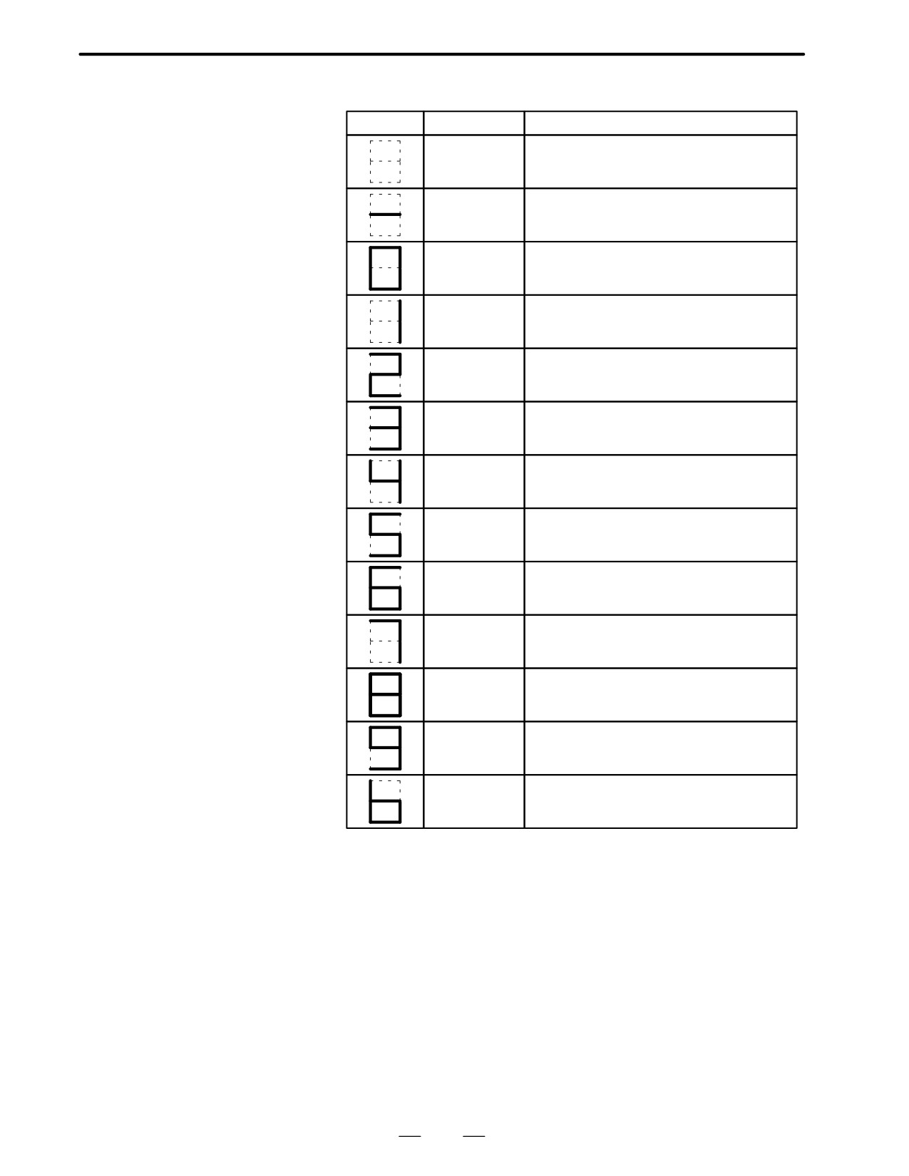
D LED display
Display
Meaning
Explanation
Power off
Power to the servo converter is not supplied.
NOT READY
Internal MMC (electro-magnetic contactor) is not
turned on.
READY
Internal MMC is turned on and the motor
becomes ready.
HV
DC voltage for driving main circuit is considerabley
Excessive
high.
voltage alarm
LV5V
+5V of control power is abnormally low.
Control power
low alarm
LVDC
DC voltage for main circuit is extremely low.
DC link voltage
low alarm
DCSW
Regenerative discharge energy in short time is
Abnormal regen-
large or regenerative discharge circuit is faulty.
erative control cir-
cuit
DCOH
Average regenerative discharge energy is large or
Excessive regen-
frequency of acc./dec. is large.
erative discharge
OH
Lights when thermostat in the servo amplifier func-
Servo amplifier
tions.
overheat
MCC
Contacts of electro-magnetic contactor is blown.
Electro magnetic
contactor
HCL
Lights when a large current flows through the main
L axis excess
circuit of L axis.
current
HCM
Lights when a large current flows through the main
M axis excess
circuit of M axis.
current
HCLM
Lights when alarge current flows throught the main
Excess current
circuit of L axis and M axis.
Note) 1st axis is L, 2nd axis is M.
D LVDC alarm
When the electro-magnetic contactor is turned on in the servo amp. or DC
voltage for the main circuit becomes low, this LED is lit.
Causes are;
1) Input voltage is insufficient.
2) Contacts of electro-magnetic contactor in servo amp. is poor.
3) Power circuit in servo amp. is abnormal.
362
B-62445E/03
8.TROUBLESHOOTING
D DCSW alarm
This alarm is lit when the transistor for regenerative discharging turns on
more than 1 second.
Its causes are;
1) Mulfunction of servo amplifier such as regenerative discharge circuit.
2) Regenerative discharge energy is excessive due to cutting conditions.
D DCOH alarm
This alarm is lit when regenerative discharge registance is overheated and
the thermost operates.
Its causes are ;
1) Average discharge energy is excessive due to frequent acc./dec. or no
use of balancer in vertical axis
2) Functioning of a thermostat in the power transformer when thermostat
signal TH1 and TH2 are connected.
D MCC alarm
When turning on MCC, if the contacts are already on.
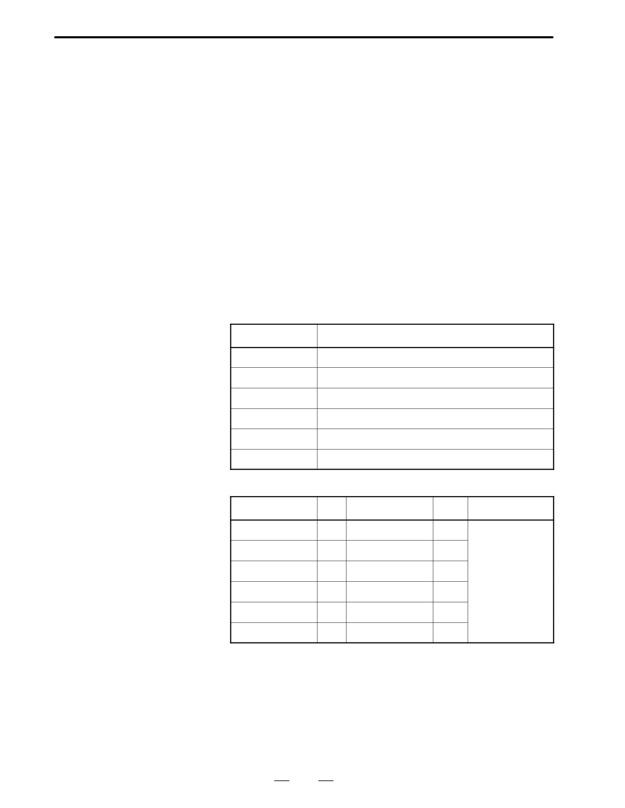
D Check terminals on
When you open the cover of the terminal board, you can see the check
servo amp.
terminal below LED.
D Terminal name and
meaning
Terminal name
Meaning
OV
0V
5V
Control power +5V(+5"0.25)
IRL
R-phase motor current of L axis
ISL
S-phase motor current of L axis
IRM
R-phase motor current of M axis
ISM
S-phase motor current of M axis
D Current/volt
Type of unit
A/V
Type of unit
(A/V)
A06B-6066-H002
1
A06B-6066-H222
1/1
Left side L axis/
Right side M axis
A06B-6066-H003
3
A06B-6066-H223
1/3
A06B-6066-H004
10
A06B-6066-H224
1/10
A06B-6066-H006
20
A06B-6066-H233
3/3
A06B-6066-H234
3/10
A06B-6066-H244
10/10
363
8. TROUBLESHOOTING
B-62445E/03
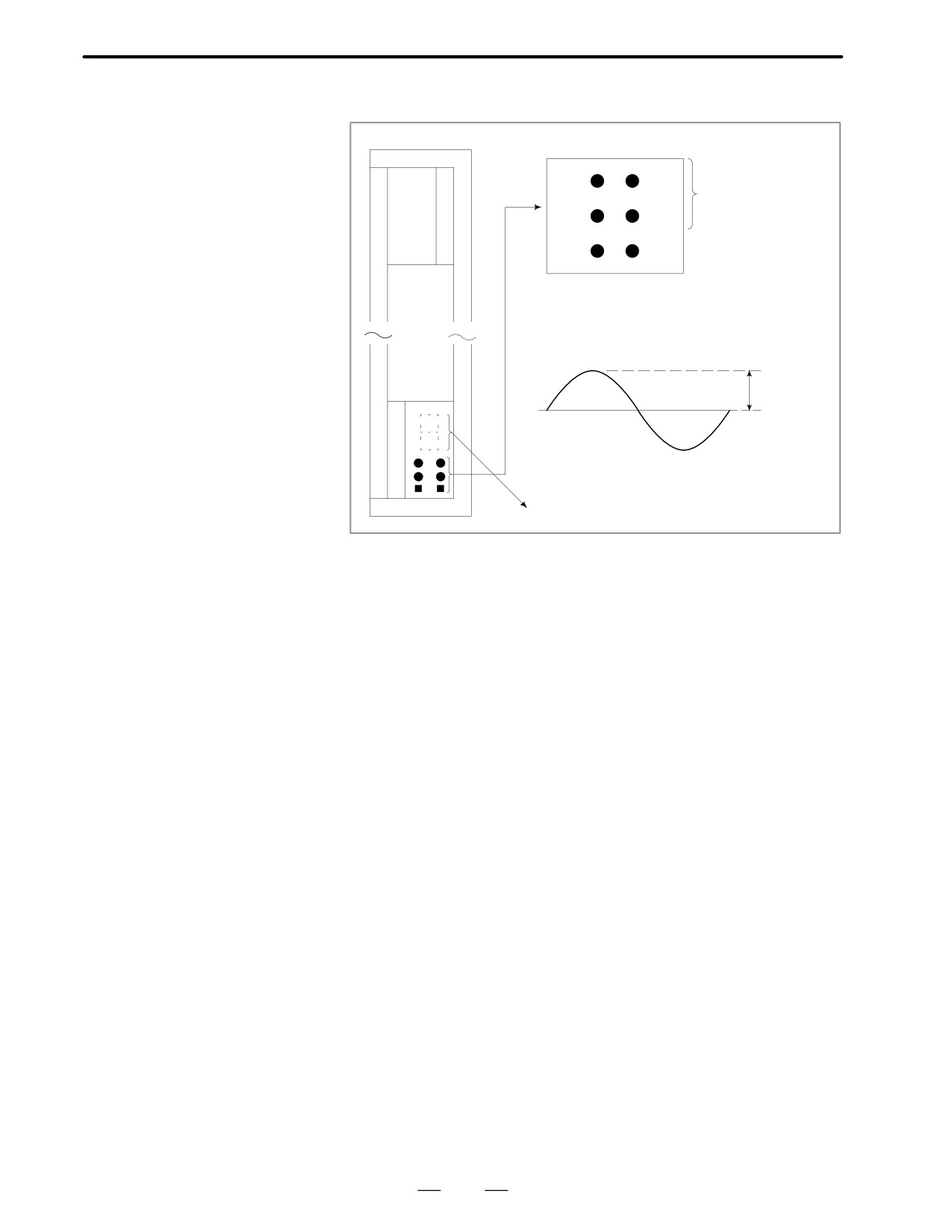
D Current waveform
(Servo amplifier)
Check terminal
IRL
IRM
Current check terminal
ISL
ISM
0V
+5V
Convert this
voltage into
current value
0V
Alarm display
364
B-62445E/03
8.TROUBLESHOOTING
Position detection signal line is disconnected or short-circuited.
8.23
ALRAM 416
(DISCONNECTION
ALARM)
Point
Check the details using the CNC’s diagnostic fucntion.
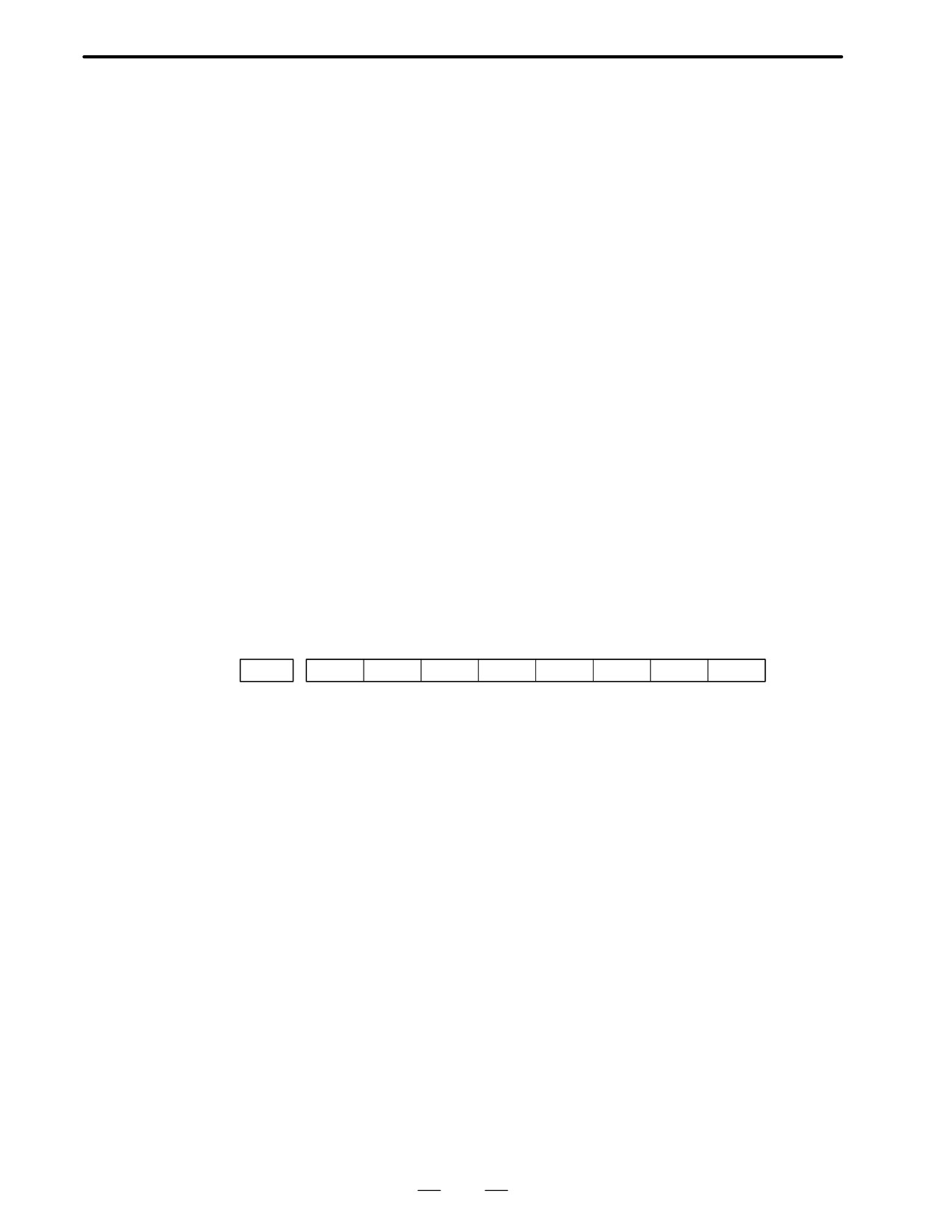
#7
#6
#5
#4
#3
#2
#1
#0
DGN
0201
ALD
EXP
→
→
1
-
-
0
Built-in serial pulse coder
³ENCX
disconnection
1
-
-
1
Separate type position
³SCALEX
detector connection
0
-
-
0
Pulse coder disconnec-
Note
tion (software)
Note
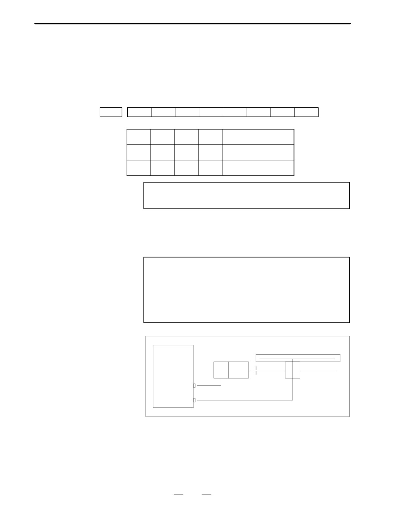
This alarm is related with full-closed system.
Causes
1
Signal cable is disconnected or short-circuitted
2
Serial pulse coder or position detector is faulty Refer to Note 1
3
Main CPU board or option 2 board is faulty Refer to Note 2
Notes
1
After the pulse coder is replaced, reference position or
machine’s standard position is different from former one.
Adjust and set it correctly.
2
When the main board is replaced, all the data stroed in
memory is lost. Set NC data again, referring to chapter 3 ”
Data input/output” .
Main CPU
Linearscale
board or Option
2 board
PC
ENCx
SCALEx
x is an axis number
From 1st axis to 4th axis are main CPU board. 5th axis or more are option
2 board.
365
8. TROUBLESHOOTING
B-62445E/03
Digital servo parameters are abnormal.
8.24
(Digital servo parameters are set incorrectly.)
ALARM 417 (DIGITAL
When alarm 315 is occured at the same time, check the cause of alarm 351
SERVO SYSTEM IS
of section 9.16.
ABNORMAL)
D Causes
1
Confirm the setting value of the following parameters:
PRM 2020 : Motor format number
PRM 2022 : Motor rotation direction
PRM 2023 : Number of pulses of velocity feedbacks
PRM 2024 : Number of pulses of position feedback
PRM 1023 : Servo axis number
PRM 2084 : Flexible feed gear ratio
PRM 2085 : Flexible feed gear ratio
Confirm the details with diagnosis function of CNC side.
2
Change the setting of this parameter to 0.
PRM 2047 : Observer parameter
3
Perform initial setting of digital servo parameters.
”Refer to setcion 5.1 ”initial setting of servo parameters” .
This data indicates the cause of servo alarm No. 417, detected by the NC. If the
alarm is detected by the servo, the PRM bit (bit 4 of DGN No. 0203) is set to
1.
#7
#6
#5
#4
#3
#2
#1
#0
0280
AXS
DIR
PLS
PLC
MOT
#0(MOT) :
The motor type specified in parameter No. 2020 falls outside the
predetermined range.
#2(PLC) :
The number of velocity feedback pulses per motor revolution, specified in
parameter No. 2023, is zero or less. The value is invalid.
#3(PLS) :
The number of position feedback pulses per motor revolution, specified in
parameter No. 2024, is zero or less. The value is invalid.
#4(DIR) :
The wrong direction of rotation for the motor is specified in parameter No.
2022 (the value is other than 111 or -111).
#6(AXS) :
In parameter No. 1023 (servo axis number), a value that falls outside the
range of 1 to the number of controlled axes is specified. (For example, 4 is
specified instead of
3.)
Alternatively, the values specified in the
parameter are not consecutive.
366
B-62445E/03
8.TROUBLESHOOTING
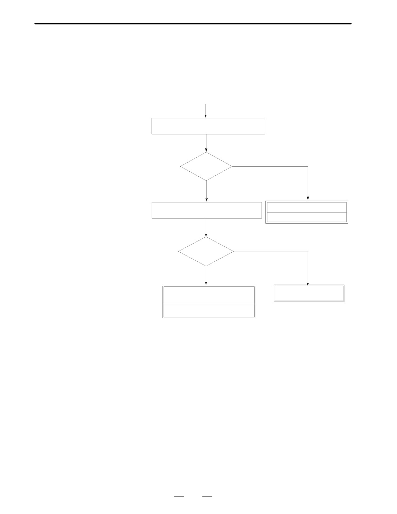
Because an ambient temperature of the control unit becomes high, a
8.25
thermostat mounted on the back panel of NC functions and informs an
ALARM 700
alarm.
(OVERHEAT AT
CONTROL SIDE)
Remedies
(START)
Check fan on the top of the control unit is oper-
ating when power is on.
NO
Operating
YES
Check temperature around the control unit is
Fun motor is faulty
high (more than 45 degrees)
Replace fan motor
YES
High tempera-
ture ?
NO
Thermostat on the back panel of NC is
Lower temperature around
faulty.
the control unit
Replace the back panel of NC.
367
8. TROUBLESHOOTING
B-62445E/03
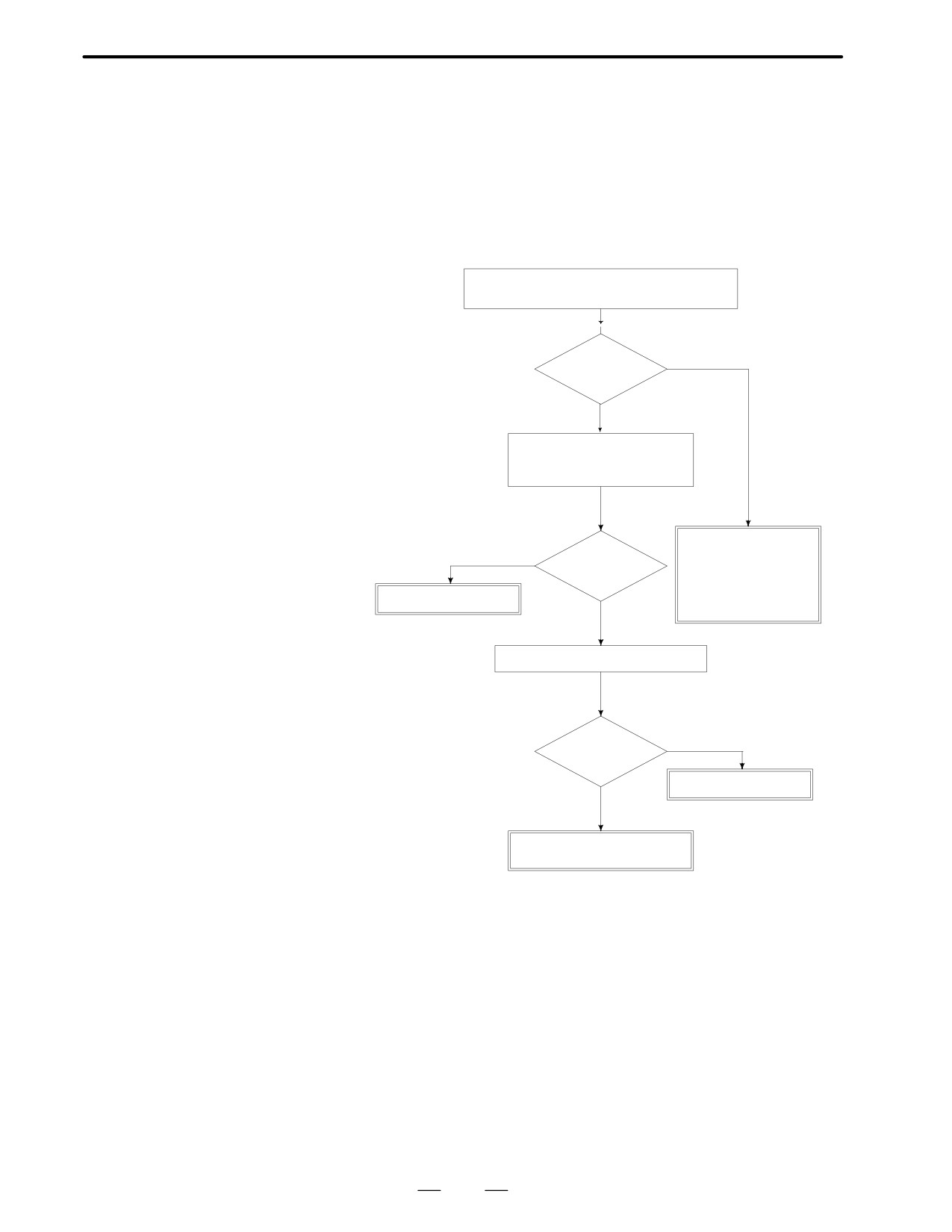
Spindle speed changes abnormally due to load.
8.26
ALARM 704 (SPINDLE
SPEED
FLUCTUATION
DETECTION ALARM)
Remedies
Check whether spindle speed is constant by view
of the speed meter on CRT.
YES
Constant ?
NO
Is a heavy cutting being per-
formed ? Confirm spindle load
on CRT.
Confirm the follow-
ing parameter :
YES
Heavy cutting?
PRM 4911
PRM 4912
PRM 4913
Reduce cutting condition
NO
PRM 4914
Doesn’t the cutting tool worn ?
YES
Worn ?
Replace tool
NO
Spindle servo unit is faulty
Spindle motor is faulty
Remedies
PRM 4911 : A ratio of spindle speed at which actual spindle speed is
regarded as arrived at a command spindle speed.
PRM 4912 : Spindle speed fluctuation ratio up to which the spindle
speed fluctuation detection alarm is not issued.
PRM 4913 : Spindle speed fluctuation that is not regarded as the spindle
speed fluctuation alarm.
PRM 4914 : Time when a spindle speed changed to when spindle speed
fluctuation detection is started.
368
B-62445E/03
8.TROUBLESHOOTING
Communication error has generated in serial spindle
8.27
ALARM 749
(SERIAL SPINDLE
COMMUNICATION
ERROR)
Causes and Remedies
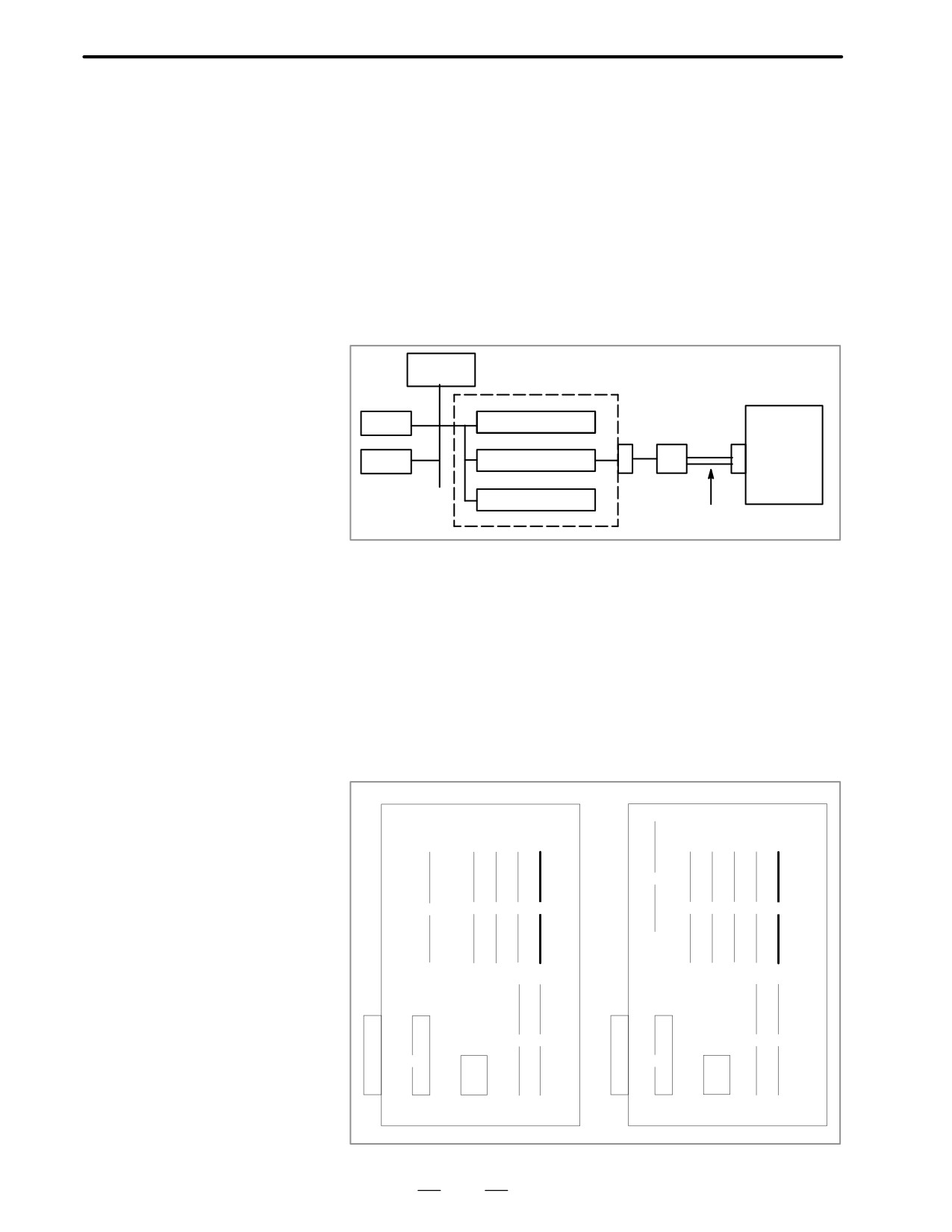
Improper connection between the main CPU board and the serial spindle.
The following reason is considered.
<Spindle module>
For Series 16 main CPU A20B-2901-0980,0981,0982
For Series 16 option A20B-2901-0984,0985,0986
Main
CPU
ROM
Calendar clock
Optical I/O link
adaptor
Spindle
RAM
Spindle control
amplifier
D/A converter
Optical cable
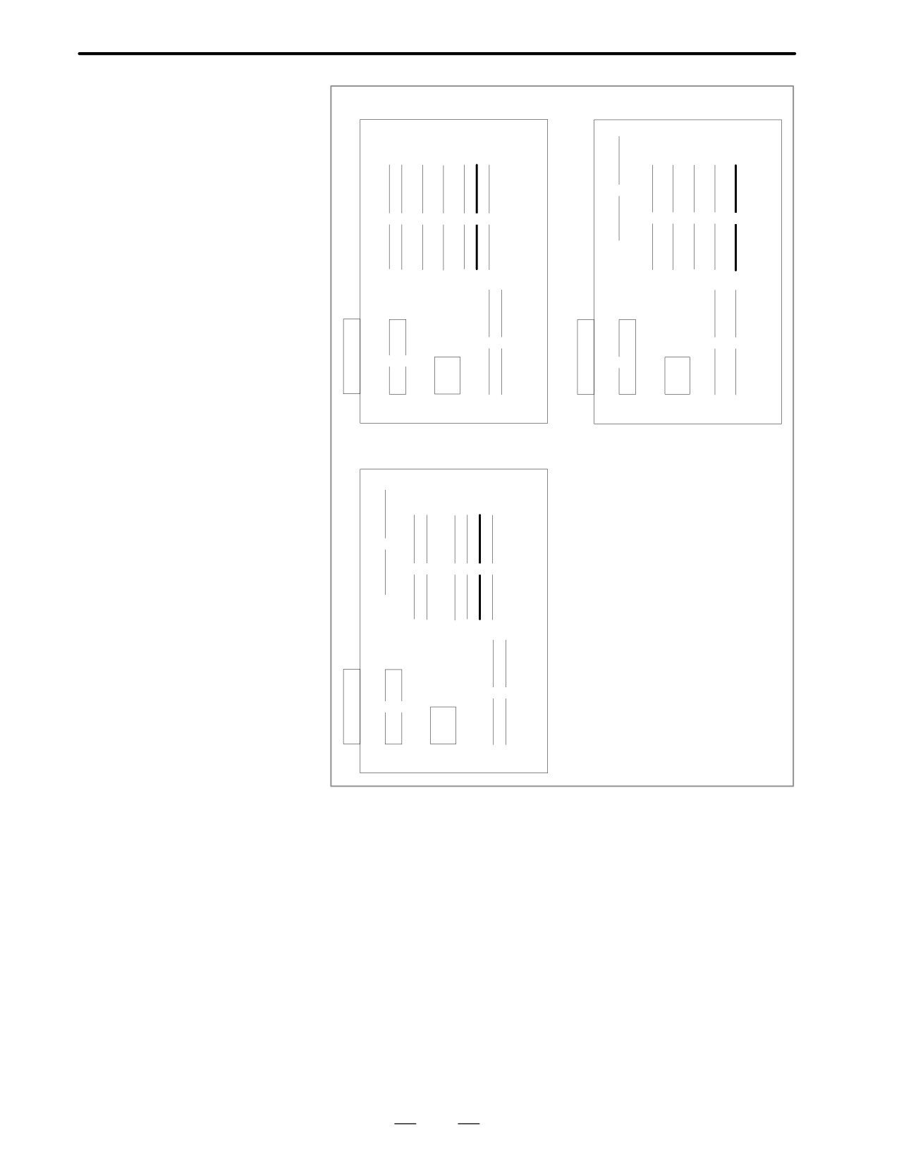
System control module is faulty.(Bold line in the figure below indicates
module mounting position.)
A cable between the main CPU board and optical I/O link adapter is
disconnected or short-circuited.
Optical I/O link adapter is faulty.
Optical cable is disconnected.
Serial spindle amplifier is faulty.
<Location of spindle module> Main CPU board
Specification
of spindle module
:
A20B-2901-0980 to
A20B-2901-0982
A16B-3200-0010
A16B-3200-0170
(1)
(1)
(2)
(3)
(4)
(5)
(2)
(3)
(4)
(5)
(6)
(6)
(7)
(7)
(8)
(8)
(9)
(9)
(10)
369
8. TROUBLESHOOTING
B-62445E/03
A16B-3200-0110
A16B-2202-0860
(1)
(1)(2)
(3)
(4)
(5)(6)
(7)
(2)
(3)
(4)
(5)
(6)
(8)(9)
(7)
(8)
(10)
(9)
(11)
(10)
A16B-3200-0160
(1)
(2)
(3)
(4) (5) (6) (7)
(8)
(9)
(10)
(11)
370
B-62445E/03
8.TROUBLESHOOTING
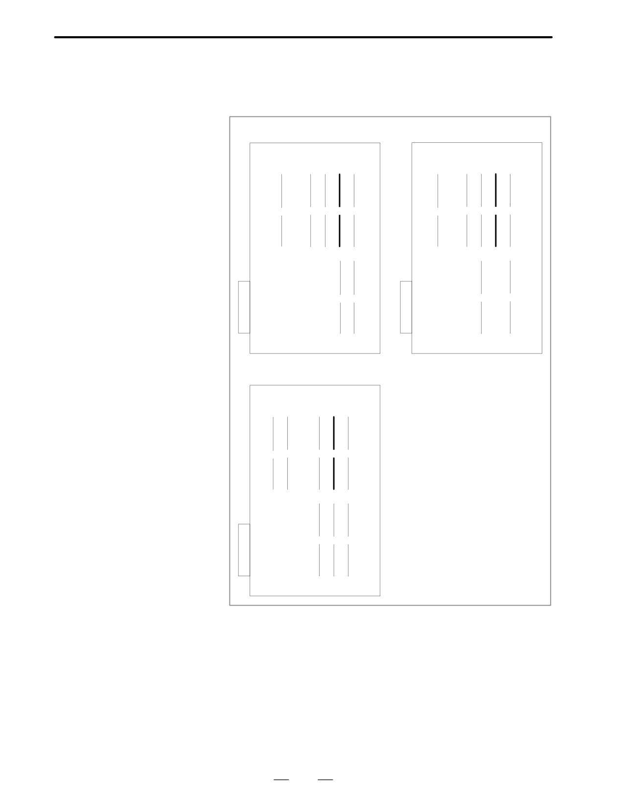
<Location of spindle module> Option 2 board
Specification
of spindle module
:
A20B-2901-0984 to
A20B-2901-0986
A16B-2202-0400, 0401
A16B-2202-0890, 0891
(1)
(2)
(3)
(4)
(5)
(1)
(2)
(3)
(4)
(5)
(6)
(7)
(6)
(7)
A16B-2202-0850, 0851, 0853
(1)
(2)
(3)
(4)
(5)
(6)
(7)
(8)
371
8. TROUBLESHOOTING
B-62445E/03
When the spindle amplifier does not become normal state immediately
8.28
after power is turned on in the serial spindle system, this alarm is
ALARM 750 (SPINDLE
informed.
SERIAL LINK
CANNOT BE
STARTED)
Points
This alarm does not occur once the system becomes ready including the
spindle system .
This alarm occurs during power on sequence before the system becomes
ready.
After the system becomes ready, serial spindle alarm is issued by alarm
749.
Causes
(1) Optical cable is in poor contact or spindle amplifier power is off.
(2) When display of spindle amplifier shows SU-01 or an alarm other than
AL-24 is displayed, power to the NC is turned on.
In this case, this alarm usually occurs when the NC’s power is turned
off while the serial spindle is operating. Turn off the power of serial
spindle once, then turn it on and starts the system.
(3) Combination of hardware is wrong.
(4) When the 2nd spindle is at the state of (1) to (3).
When the 2nd spindle is used, parameter is set as follows :
Bit 4 of parameter no.3701 is 1: No. of serial spindles connected is 2.
Details of Alarms
Confirm the details of troubles on diagnostic 409.
#7
#6
#5
#4
#3
#2
#1
#0
DGN
0409
SPE
S2E
S1E
SHE
#3(SPE)
0 : In spindle serial control, the serial spindle parameters satisfies the
starting conditions for spindle amplifier.
1 : In spindle serial control, the serial spindle parameters do not satisfy
the starting conditions for spindle amplifier.
#2(S2E)
0 : At the start of spindle serial control, the spindle is normal.
1 : At the start of spindle serial control, the spindle is abnormal.
#1(S1E)
0 : The serial communication module of the CNC side is normal.
1 : The serial communication module of the CNC side is abnormal.
#0(SPE)
0 : Serial communication module on the CNC side is normal.
1 : Serial communication module was detected to be abnormal on the
CNC side.
372

B-62445E/03
8.TROUBLESHOOTING
Remedies
Reform the following countermeasures based on the above
configurations:
(1) #3(SPE)1: In spindle serial control, the serial spindle parameters does
not satisfy the starting conditions for spindle amplifier.
↓
Confirm the settings of parameters 4000s.
Especially checks the parameters those are changed from the standard
parameters.
(2) #2(S2E)1: At the start of spindle serial control, when an abnormality
is found in the 2nd spindle side.
↓
Check the 2nd spindle parameters and connections to see whether the
spindle is mechanically and electronically connected to the spindle.
↓
If the above settings and connections are right, the module of (4) or the
spindle amplifier itself may be defective.
(3) #1(SIE)1: When an abnormality is found in the 1st spindle at the start
of serial spindle control, exchange the unit if the following
check items are not concerned.
↓
Check the parameters and connections at the 1st spindle to see whether
the 1st spindle is mechanically and electrically connected.
↓
If the parameters and connections are correct, the system control
module shown below or the spindle amplifier itself is faulty.
(4) #0(SPE)1: The serial communication module is detected to be
abnormal. Exchange the following module :
373
8. TROUBLESHOOTING
B-62445E/03
<Location of spindle module> Main CPU board
Specification
of spindle module
:
A20B-2901-0980 to
A20B-2901-0982
A16B-3200-0010
A16B-3200-0170
(1)
(1)
(2)
(3)
(4)
(5)
(2)
(3)
(4)
(5)
(6)
(6)
(7)
(7)
(8)
(8)
(9)
(9)
(10)
A16B-3200-0110
A16B-2202-0860
(1)
(1)(2)
(3)
(4)
(5)(6)
(7)
(2)
(3)
(4)
(5)
(6)
(8)(9)
(7)
(8)
(10)
(9)
(11)
(10)
374
B-62445E/03
8.TROUBLESHOOTING
A16B-3200-0160
(1)
(2)
(3)
(4) (5) (6) (7)
(8)
(9)
(10)
(11)
375
8. TROUBLESHOOTING
B-62445E/03
<Location of spindle module> Option 2 board
Specification of spindle module:A20B-2901-0984 to A20B-2901-0986
A16B-2202-0400, 0401
A16B-2202-0890, 0891
(1)
(2)
(3)
(4)
(5)
(1)
(2)
(3)
(4)
(5)
(6)
(7)
(6)
(7)
A16B-2202-0850, 0851, 0853
(1)
(2)
(3)
(4)
(5)
(6)
(7)
(8)
376

B-62445E/03
8.TROUBLESHOOTING
With serial spindle system, an alarm on the spindle unit is informed to the
8.29
CNC.
ALARM 751,761
751 ( Alarm detection by 1st spindle )
(SPINDLE ALARM)
761( Alarm detection by 2nd spindle )
The alarm contents is displayed by AL-xx on the display of spindle amp.
Refer to appendix 2.3 or 2.4 for the contents.
The CNC holds an alarm number display (AL-xx).
D Point
This alarm informs of trouble of spindle control unit.
Repair the spindle side by the method of remedy for each alarm.
D Causes and Remedies
Refer to Appendix 2.3 or 2.4 for details.
377

8. TROUBLESHOOTING
B-62445E/03
ROM parity error occurred.
8.30
ALARM 900 (ROM
PARITY ERROR)
Causes and Remedies
(1) ROM module mounted on the main CPU board or ROM is defective.
SYSTEM ALARM
B0A1-02
900
ROM PARITY
CNC ROM MODULE : FC0
Defective file
or ROM is displayed
MACRO ROM MODULE
SERVO ROM
Confirm the series and versions of control software those are displayed
on upper right of the screen.
*FROM module may be written data by machine tool builder.
*Mounting position of ROM/FROM module
378
B-62445E/03
8.TROUBLESHOOTING
<Main CPU board>
A16B-3200-0010
A16B-3200-0170
(1)
(1)
(2)
(3)
(4)
(5)
(2)
(3)
(4)
(5)
(6)
(6)
(7)
(7)
(8)
(8)
(9)
(9)
(10)
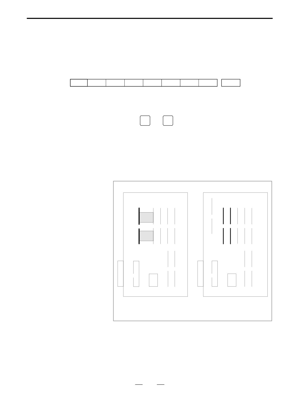
(1) FROM module
(3) FROM module
Specification
: A20B-2902-0080X0082
Specification
: A20B-2902-0341,0343
A20B-2902-0090X0094
(10)
BOOT ROM
(9) BOOT ROM
A16B-3200-0110
A16B-2202-0860
(1)
(1)(2)
(3)
(4)
(5)(6)
(7)
(2)
(3)
(4)
(5)
(6)
(8)(9)
(7)
(8)
(10)
(9)
(11)
(10)
(2) FROM module
(3) FROM module
Specification
: A20B-2902-0341,0343
Specification
: A20B-2902-0341,0343
(11)
BOOT ROM
A20B-2902-0410,0411
(10)
BOOT ROM
379
8. TROUBLESHOOTING
B-62445E/03
A16B-3200-0160
(1)
(2)
(3)
(4) (5) (6) (7)
(8)
(9)
(10)
(11)
(2) FROM module
Specification
: A20B-2902-0341,0343
A20B-2902-0410,0411
(11)
BOOT ROM
380
B-62445E/03
8.TROUBLESHOOTING
Parity error of RAM module that stores part programs.
8.31
ALARM 910 TO 915
(SRAM PARITY)
Points
A parity bit is prepared for writing data in memory correctly. There are
odd-number parity and even-number parity.
#7
#6
#5
#4
#3
#2
#1
#0
#P
(Parity bit)
1
0
1
1
0
1
1
1
0
(Even-number
parity)
Causes and Remedies
(1) Causes are faults of RAM on the main board or RAM module, or fault
of data memorized in RAM. When this alarm occurs immediately
after power is turned on, once turn off power, then turn on power while
pushing
RESET
and
DELETE
key to perform memory all clear
If parity error is not released by clearing all memory, RAM on the main
board or RAM module may be faulty. Change (4)RAM module on
main CPU board.
Set all the data again, referring to chapter 3 “data input/output”.
D RAM module mounting
1
: SRAM module (Part program editing, parameters)
position
<Main CPU board>
A16B-3200-0010
A16B-3200-0170
(10)
(1)
(1)
(2)
(3)
(4)
(5)
(2)
(3)
(4)
(5)
(6)
(10)
(6)
(7)
(7)
(8)
(8)
(9)
(9)
(10)
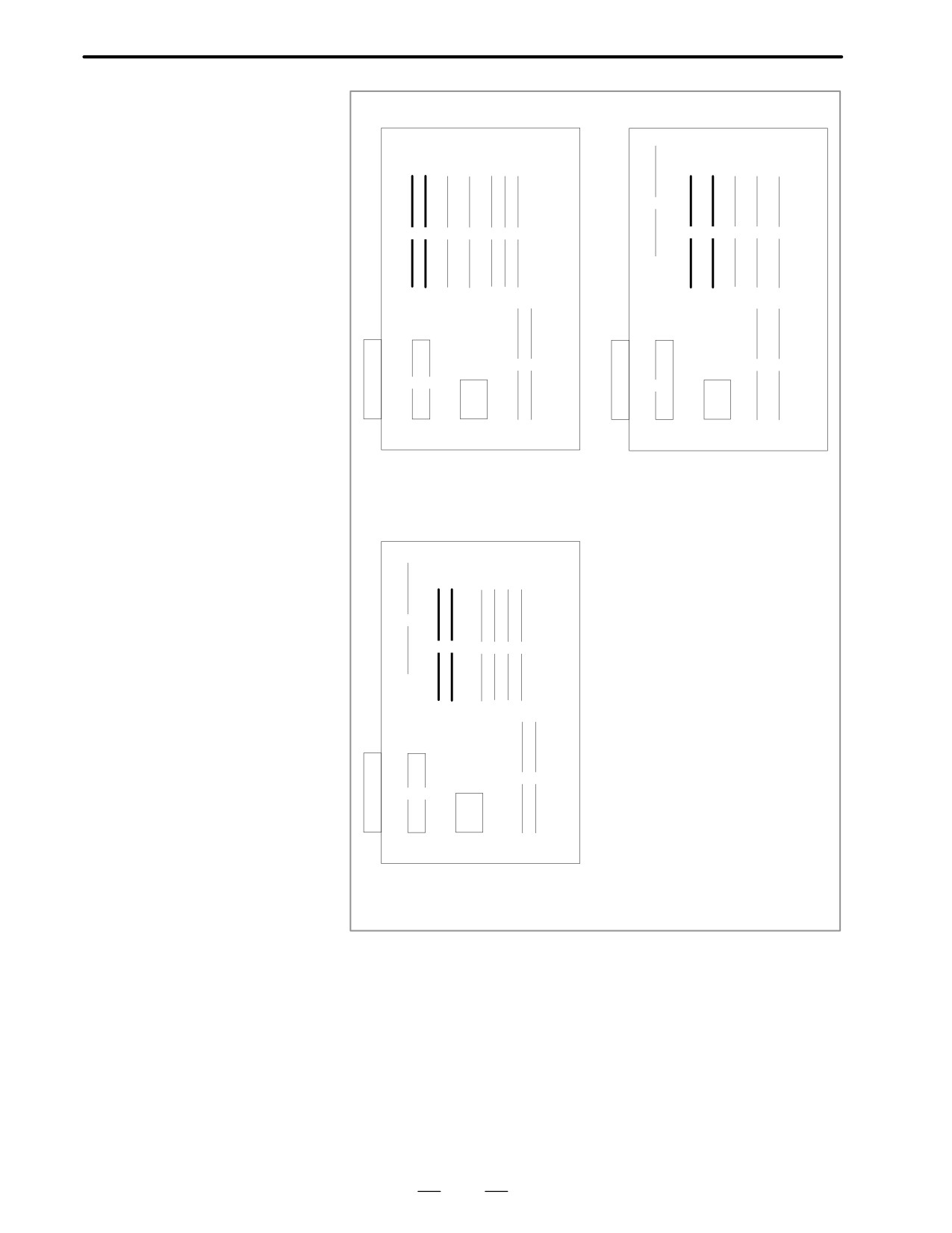
(1) FROM/SRAM module
(2) Additional SRAM module
Specification
: A20B-2902-0080
Specification
: A20B-2902-0350X0352
A20B-2902-0090,0093,0094
(3) FROM/SRAM module
(10)
SRAM
Specification
: A20B-2902-0341,0343
mounted on main CPU board
381
8. TROUBLESHOOTING
B-62445E/03
A16B-3200-0110
A16B-2202-0860
(1)
(1)(2)
(3)
(4)
(5)(6)
(7)
(2)
(3)
(4)
(5)
(6)
(8)(9)
(7)
(8)
(10)
(9)
(11)
(10)
(1) Additional SRAM module
(2) Additional SRAM module
Specification
: A20B-2902-0350X0352
Specification
: A20B-2902-0350X0352
(2) FROM/SRAM module
FROM/SRAM module
Specification
: A20B-2902-0341,0343
Specificaiton
: A20B-2902-0341,0343
A20B-2902-0410,0411
A16B-3200-0160
(1)
(2)
(3)
(4)(5)
(6)(7)
(8)
(9)
(10)
(11)
(1) Addition SRAM module
Specification
: A20B-2902-0350X0352
(10)
FROM/SRAM module
Specification
: A20B-2902-0341,0343
382

B-62445E/03
8.TROUBLESHOOTING
(2) Low voltage of memory back up battery. Battery alarm occurs if
voltage is 2.6V or less (3.0V rating).
When the memory back up battery voltage is lowered, BAT is
displayed at lower part of the screen.
When battery alarm is lit, replace with new lithium batteries as soon
as possible.
Refer to 2.8 battery replacing item and change the batteries.
(3) Power supply unit is faulty
When alarm turns off by an operation of clearing all the memory,
power supply unit may also be faulty.
383
8. TROUBLESHOOTING
B-62445E/03
A parity error occurred in the DRAM module.
8.32
ALARM 916 (DRAM
PARITY ERROR)
Cause and action
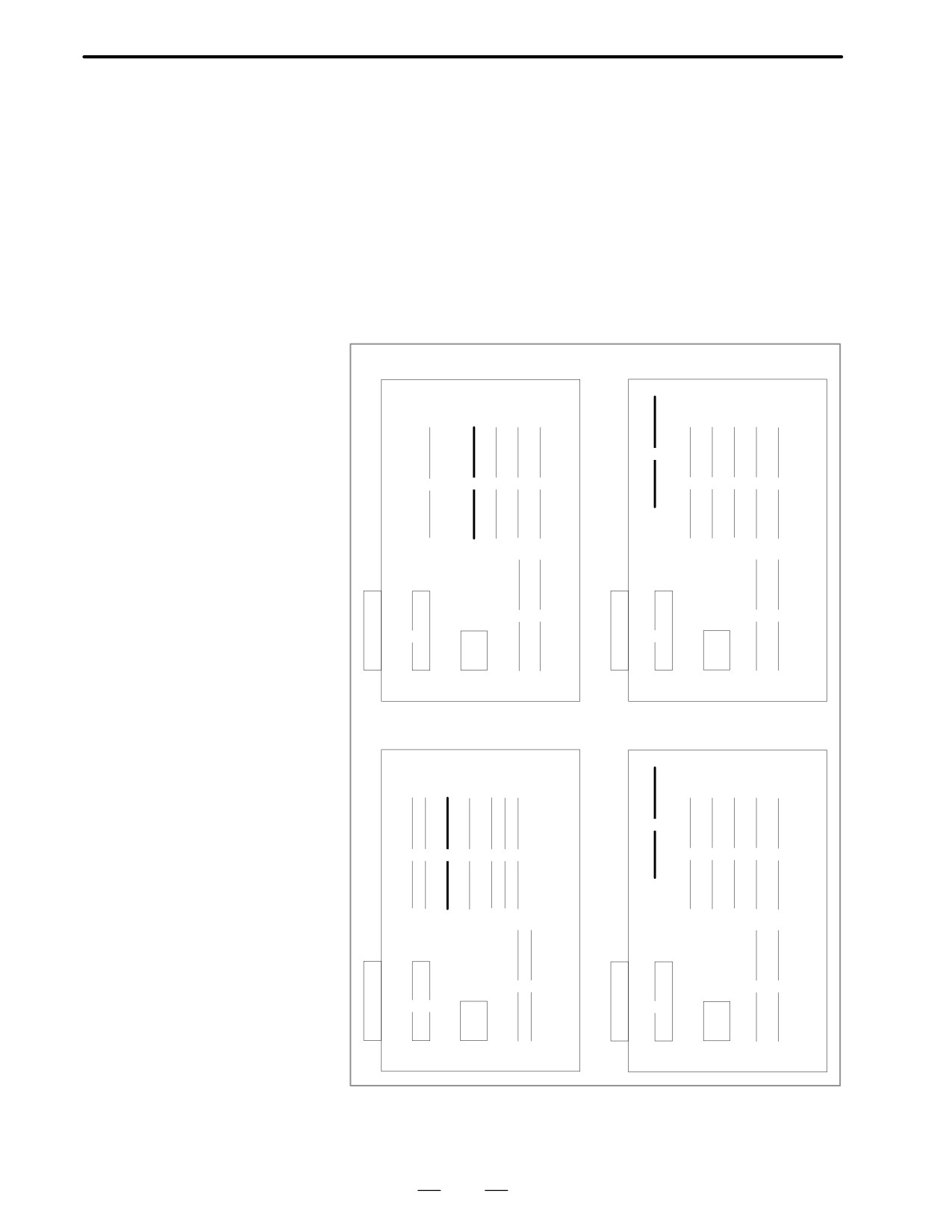
The DRAM module on the main CPU board may be faulty. Replace the
DRAM module.
<Location of DRAM module> Main CPU board
Specification: A20B-2901-0940 ~ 0942
A16B-3200-0010
A16B-3200-0170
(1)
(1)
(2)
(3)
(4)
(5)
(2)
(3)
(4)
(5)
(6)
(6)
(7)
(7)
(8)
(8)
(9)
(9)
(10)
A16B-3200-0110
A16B-2202-0860
(1)
(1)(2)
(3)
(4)
(5)(6)
(7)
(2)
(3)
(4)
(5)
(6)
(8)(9)
(7)
(8)
(10)
(9)
(11)
(10)
384
B-62445E/03
8.TROUBLESHOOTING
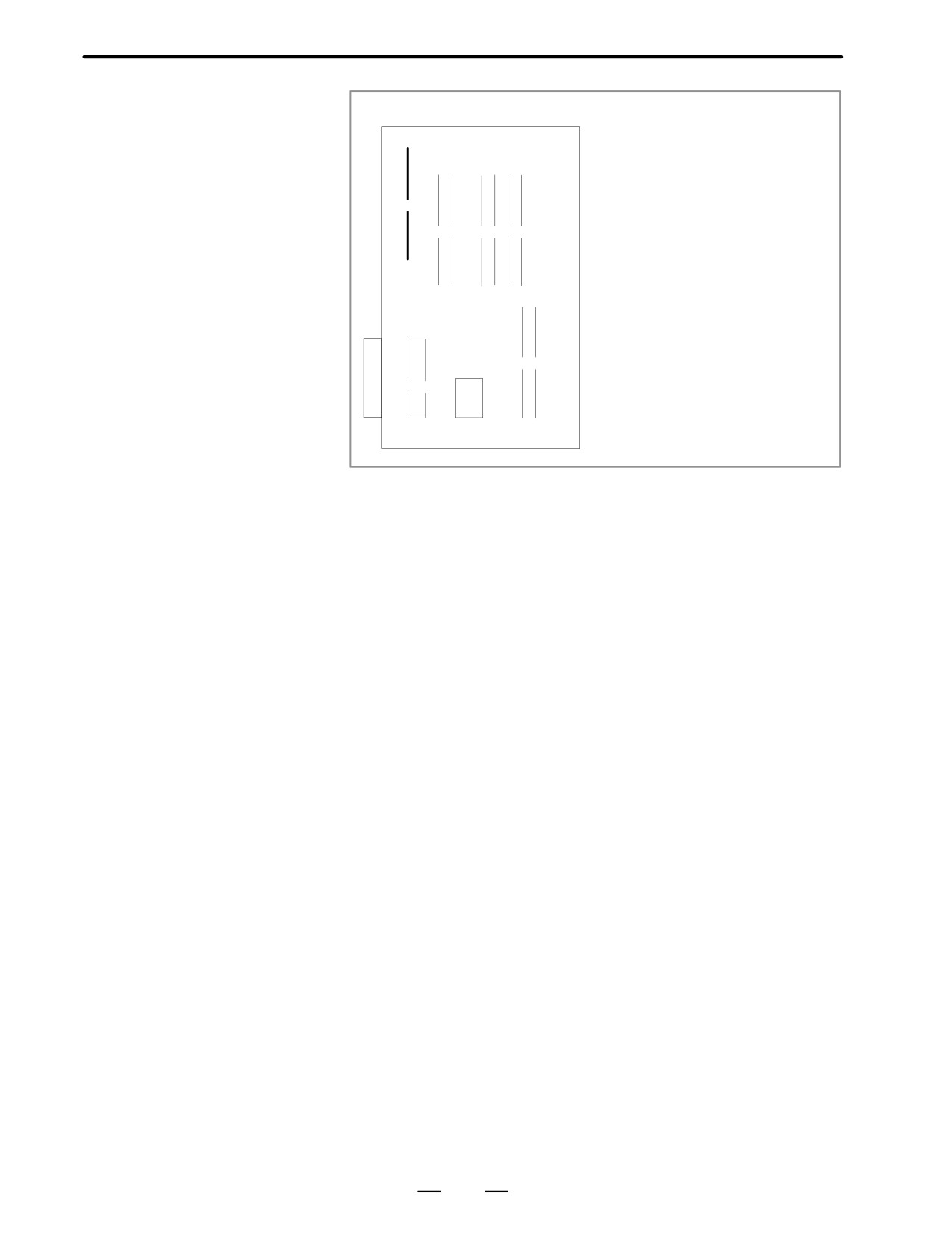
A16B-3200-0160
(1)
(2)
(3)
(4) (5) (6) (7)
(8)
(9)
(10)
(11)
385

8. TROUBLESHOOTING
B-62445E/03
920: Watch dog alarm or RAM parity in servo control module
8.33
has occurred in the 1st or 2nd axis
ALARM 920 TO 923
921: Above alarm has occurred in the 3rd or 4th axis
(WATCH DOG OR
922: Above alarm has occurred in the 5th or 6th axis
RAM PARITY)
923: Above alarm has occurred in the 7th or 8th axis
points
The timer used to monitor the operation of CPU is called the watch dog
D Watch dog timer alarm
timer. The CPU resets timer time every time a constant time has passed.
When an error occurs in CPU or peripheral device, timer is not reset but
the alarm is informed.
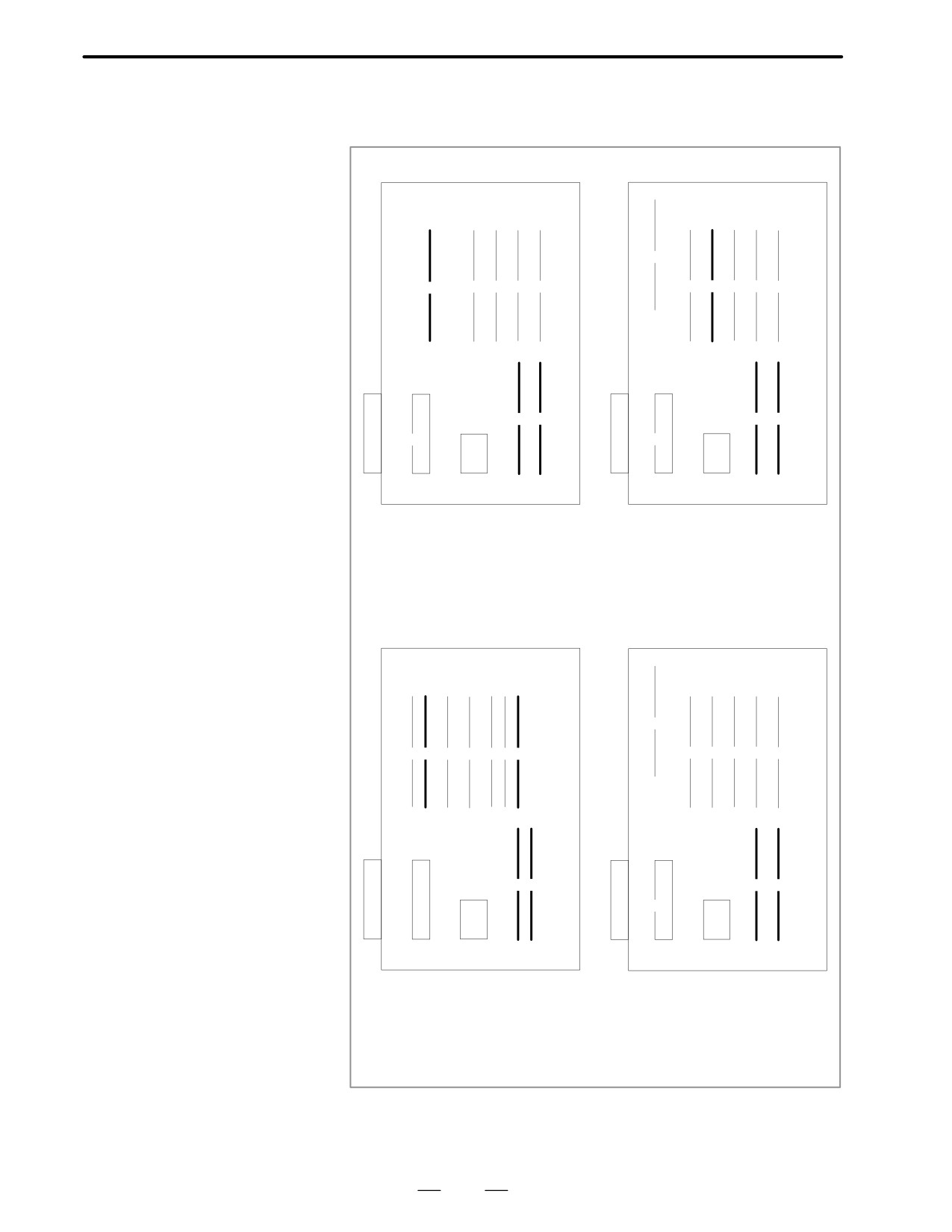
D RAM parity error
Refer to alarm 910 to 915
Causes and Remedies
D Servo control module is
The servo module includes servo RAM, watch dog timer circuit, etc.
faulty
Defectiveness of hardware, abnormality or malfunctioning of detection
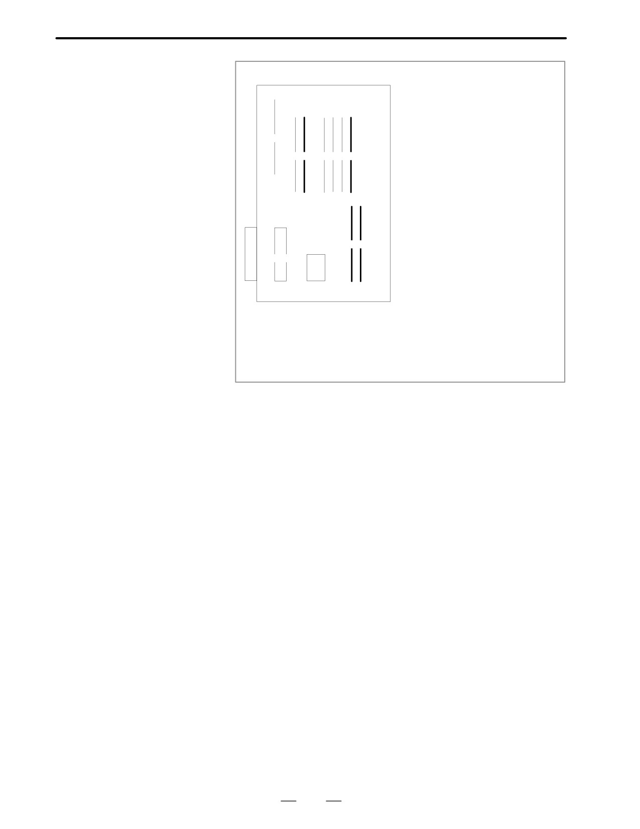
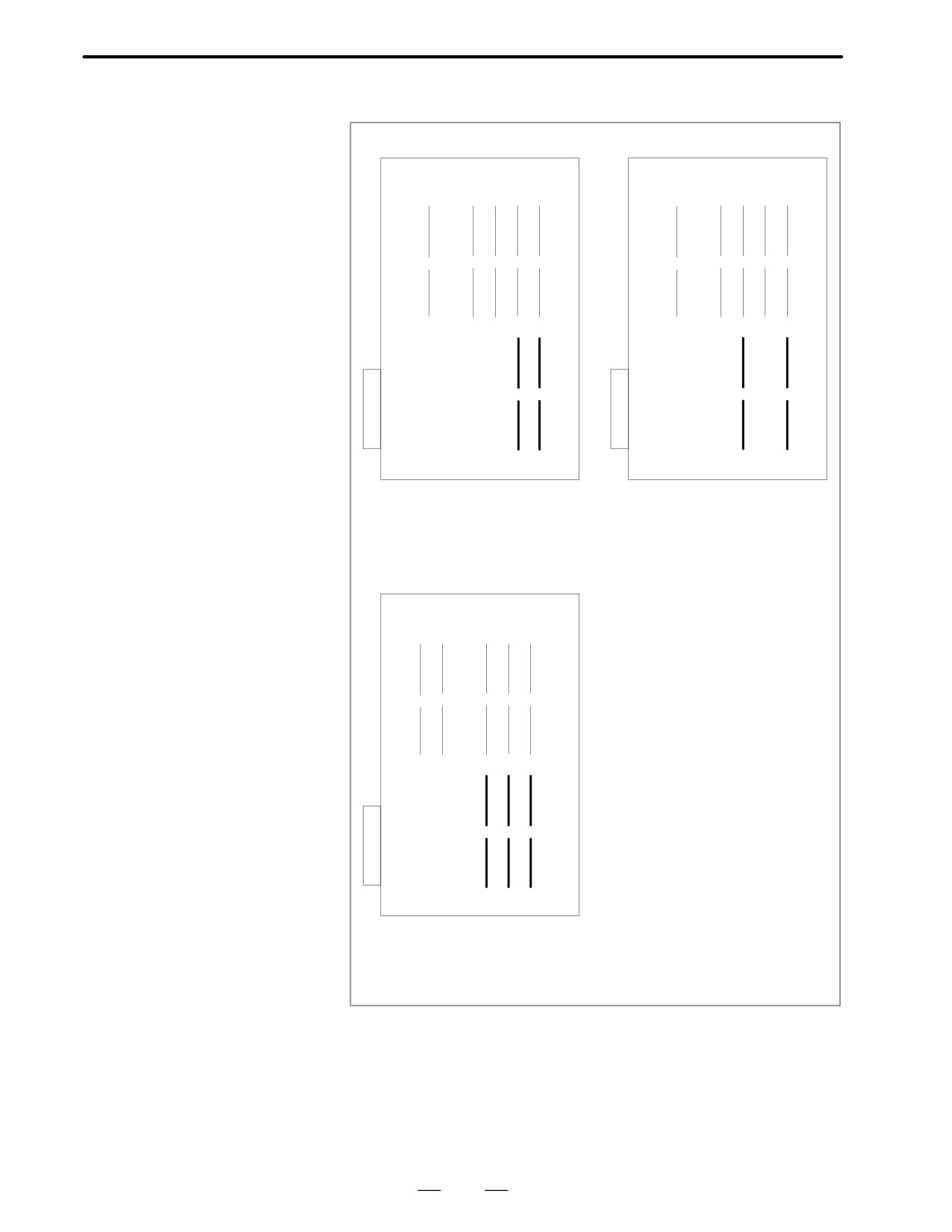
circuit or the like is considered. Therefore, replace servo module on the
main CPU board for alarm 920 and 921; replace servo module on the
option 2 board for alarm 922 and 923.
Main
CPU
ROM
Servo module
(A20B-2902-0060, A20B-2902-0061)
RAM
D Main CPU board is faulty
CPU or peripheral circuits may be faulty. Replace the main CPU board.
D CNC control software
Software may not work properly due to failure of FROM module. Change
ROM module is faulty
FROM module.
D Power supply unit is
DC output voltage of power supply unit may be faulty. Replace the power
faulty
supply unit.
386
B-62445E/03
8.TROUBLESHOOTING
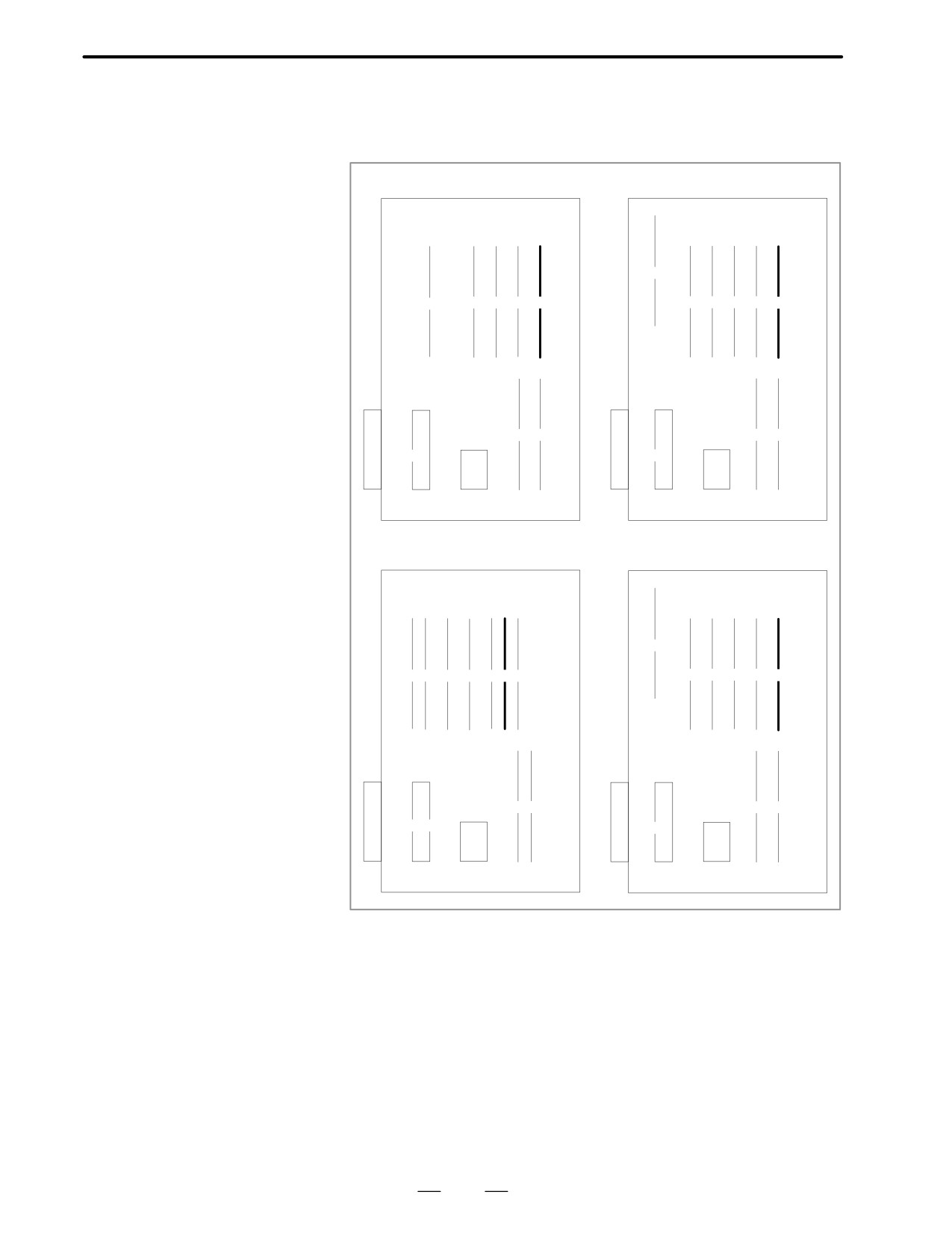
<Location of module> Main CPU board
A16B-3200-0010
A16B-3200-0170
(1)
(1)
(2)
(3)
(4)
(5)
(2)
(3)
(4)
(5)
(6)
(6)
(7)
(7)
(8)
(8)
(9)
(9)
(10)
(1) FROM module
(3) FROM module
Specification
: A20B-2902-0080X0082
Specification
: A20B-2902-0341,0343
A20B-2902-0090X0094
A20B-2902-0410X0411
(7) Servo module of 1st, 2nd axis
(7) Servo module of 1st, 2nd axis
Specification
: A20B-2902-0060X0061
Specification
: A20B-2902-0060X0061
(6) Servo module of 3rd, 4th axis
(6) Servo module of 3rd, 4th axis
Specification
: A20B-2902-0060X0061
Specification
: A20B-2902-0060X0061
A16B-3200-0110
A16B-2202-0860
(1)
(1)(2)
(3)
(4)
(5)(6)
(7)
(2)
(3)
(4)
(5)
(6)
(8)(9)
(7)
(8)
(10)
(9)
(11)
(10)
(2) FROM Module
(3) FROM module
Specification
: A20B-2902-0341,0343
Specification
: A20B-2902-0341,0343
(7) Servo module of 1st, 2nd axis
A20B-2902-0410X0411
Specification
: A20B-2902-0060X0061
(8) Servo module of 1st, 2nd axis
(9) Servo module of 3rd, 4th axis
Specification
: A20B-2902-0060X0061
Specification
: A20B-2902-0060X0061
(7) Servo module of 3rd, 4th axis
(8) Servo module of 5th, 6th axis
Specification
: A20B-2902-0060X0061
Specification
: A20B-2902-0060X0061
387
8. TROUBLESHOOTING
B-62445E/03
A16B-3200-0160
(1)
(2)
(3)
(4) (5) (6) (7)
(8)
(9)
(10)
(11)
(3) FROM module
Specification
: A20B-2902-0341, 0343
(7) Servo module of 1st, 2nd axis
Specification
: A20B-2902-0060X0061
(9) Servo module of 3rd, 4th axis
Specification
: A20B-2902-0060X0061
(8) Servo module of 5th, 6th axis
Specification
: A20B-2902-0060X0061
388
B-62445E/03
8.TROUBLESHOOTING
<Location of module> Option 2 board
A16B-2202-0400,0401
A16B-2202-0890,0891
(1)
(2)
(3)
(4)
(5)
(1)
(2)
(3)
(4)
(5)
(6)
(7)
(6)
(7)
(7) Servo module of 5th, 6th axis
(7) Servo module of 5th, 6th axis
Specification
: A20B-2902-0060X0061
Specification
: A20B-2902-0060X0061
(6) Servo module of 7th, 8th axis
(6) Servo module of 7th, 8th axis
Specification
: A20B-2902-0060X0061
Specification
: A20B-2902-0060X0061
A16B-2202-0850,0851,0853
(1)
(2)
(3)
(4)
(5)
(6)
(7)
(8)
(6) Servo module of 5th, 6th axis
Specification
: A20B-2902-0060X0061
(7) Servo module of 3rd, 4th axis
Specification
: A20B-2902-0060X0061
(8) Servo module of 1st, 2nd axis
Specification
: A20B-2902-0060X0061
389
8. TROUBLESHOOTING
B-62445E/03
The digital servo module is not mounted.
8.34
ALARM 924 (SERVO
MODULE MOUNTING
ERROR)
Note
This alarm may not occur during normal operaion.
This alarm may be generated when a PCB is changed for
maintenance.
D Causes and remedies
Check installation of servo module on main CPU or option 2 board.
For location of servo module, refer to an installation diagram of alarm 920
to 923.
<Series 16 Main CPU board>
1st to 4th axis servo module
(A20B-2902-0060 or A20B-2902-0061)
<Option 2 board>
5th to 8th axis servo module
(A20B-2902-0060 or A20B-2902 -0061)
Unless these boards are mounted correctly, if this alarm still generates,
change main CPU board, option 2 board and/ or servo module.
D Kinds of servo module
A20B-2902-0060
Standard
A20B-2902-0061
For Learning control
390
B-62445E/03
8.TROUBLESHOOTING
CPU error (illeagal interrupt) has generated.
8.35
ALARM 930 (CPU
ERROR)
Causes and Remedies
1)
Main CPU board is faulty
An interrupt which will not occur during usual operation has
generated.
Peripheral circuit of the CPU may be abnormal. Change the main
CPU board. If operation is performed normally by power off and
on, noise may be a cause. Refer to 8. Suppressing Noise.
391
8. TROUBLESHOOTING
B-62445E/03
An error occurred when RAM test is being executed.
8.36
ALARM 950 (PMC
SYSTEM ALARM)
Causes and Remedies
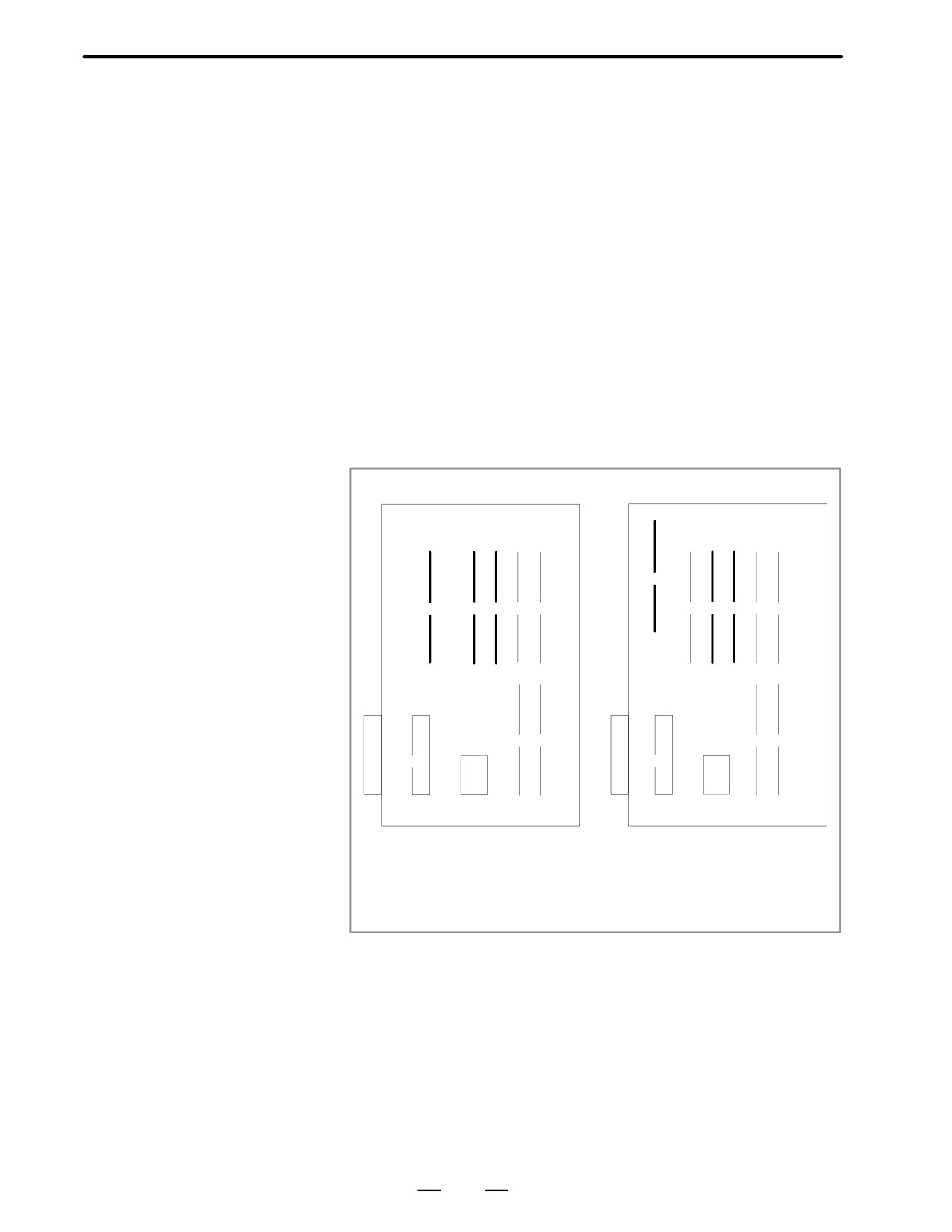
The following causes are considered :
D For PMC-RB
Fault on Main CPU board
⋅
PMC control module (3) is faulty.
⋅
DRAM module (2) is faulty.
⋅
FROM module (1) is faulty.
D For PMC-RC
Fault on Main CPU board
⋅
PMC control module (5) is faulty.
⋅
DRAM module (4) is faulty (Option 3 board)
⋅
Option 3 board is faulty.
Module mounting
position
(Main CPU)
A16B-3200-0010
A16B-3200-0170
(1)
(1)
(2)
(3)
(4)
(5)
(2)
(3)
(4)
(5)
(6)
(6)
(7)
(7)
(8)
(8)
(9)
(9)
(10)
(1) FROM module
(1) DRAM modle
Specification
: A20B-2902-0080X0082
Specification
: A20B-2901-0040X0942
A20B-2902-0090X0094
(3) FROM module
(2) DRAM module
Specification
: A20B-2902-0341,0343
Specification
: A20B-2901-0940X0942
: A20B-2902-0410X0411
(3) PMC control module
(4) PMC control module
Specification
: A20B-2901-0960X0961
Specification
: A20B-2901-0960X0961
392