FANUC Series 16 / 160 / 18 / 180 – Model B. Maintenance Manual - page 12
B-62445E/03
8.TROUBLESHOOTING
A16B-3200-0160
(1)
(2)
(3)
(4) (5) (6) (7)
(8)
(9)
(10)
(11)
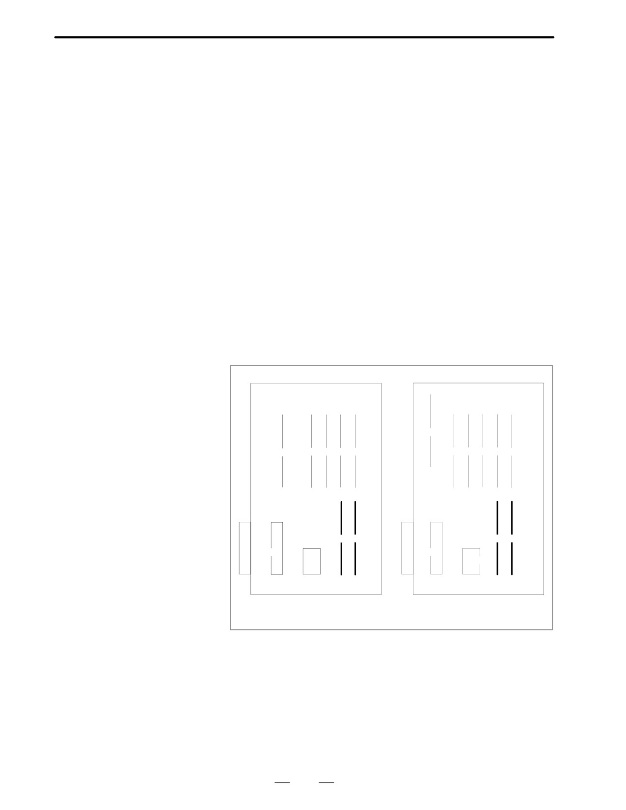
(ii)
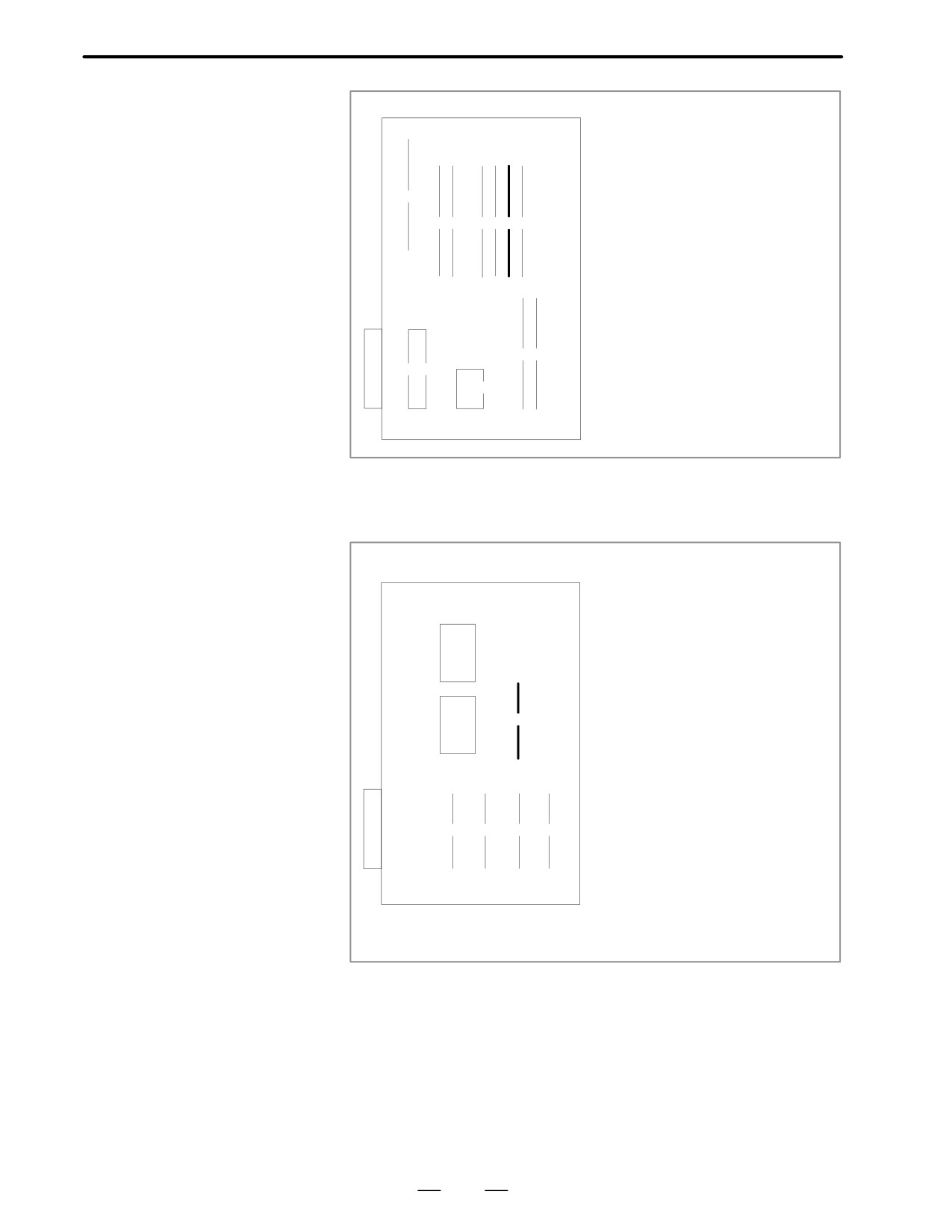
When parameter no. 0020 is 3 (JD5C,JD6A of option 1 board)
Because communication control module (5) may be faulty,
replace the module.
(Option 1 board)
(7)
(5)
(6)
(1)
(2)
(3)
(4)
(5) Change communication control module
Specification : A20B-2900-0361
331
8. TROUBLESHOOTING
B-62445E/03
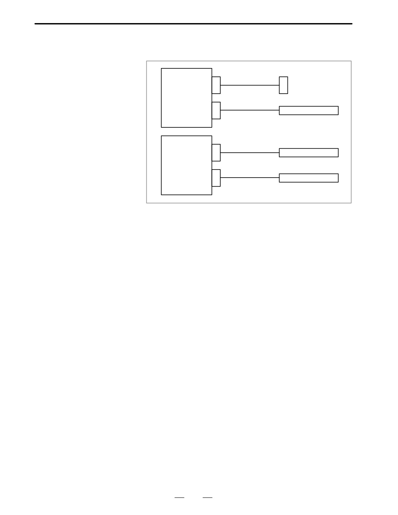
(d) Cable between NC and I/O device is faulty.
Check the cable for disconnection or wrong connection.
Main CPU board
R232-1(JD5A)
Punch panel
R232-1(JD5B)
Tape reader
Option 1 board
R232-1(JD5C)
Host computer
R232-1(JD6A)
Host computer
332
B-62445E/03
8.TROUBLESHOOTING
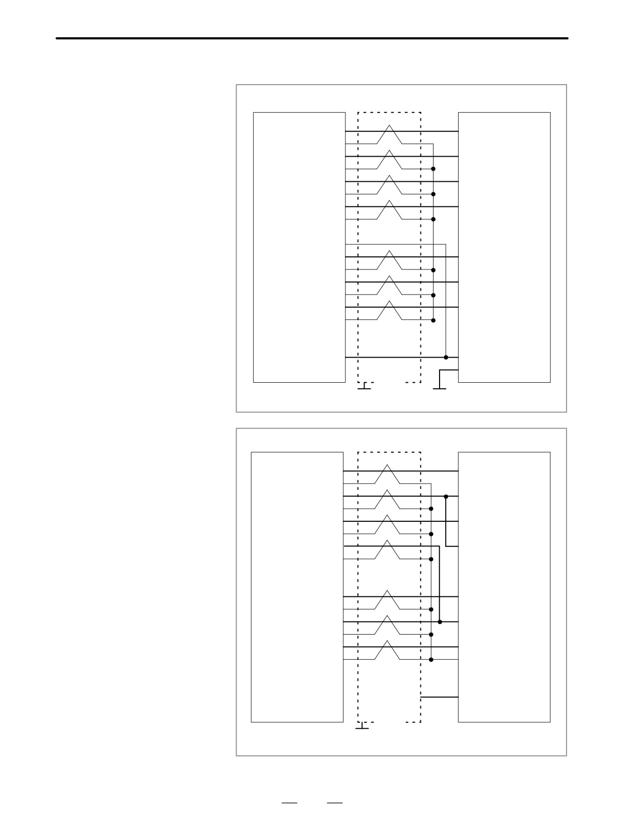
< Cable connection>
R232-1 (JD5A)
Punch panel
R232-2 (JD5B)
RD
(01)
(03) RD
0V
(02)
DR
(03)
(06) DR
0V
(04)
CS
(05)
(05) CS
0V
(06)
CD
(07)
(08) CD
0V
(08)
(09)
+24V (10)
SD
(11)
(02) SD
0V
(12)
ER
(13)
(20) ER
0V
(14)
RS
(15)
(04) RS
0V
(16)
(07) SG
(17)
(18)
+24V (19)
(25) +24V
(20)
(01) FG
Shield
G
G
Connector :DBM-25Ss
Connector : Half-pitch 20-pins
R232-3 (JD5C)
Host computer
RD
(01)
(02) SD
0V
(02)
DR
(039
(20) ER
0V
(04)
CS
(05)
(04) RS
0V
(06)
CD
(07)
(08) CD
0V
(08)
(09)
+24V (10)
SD
(11)
(03) RD
0V
(12)
ER
(13)
(06) DR
0V
(14)
RS
(15)
(05) CS
0V
(16)
(07) SG
(17)
(18)
+24V (19)
(25) +24V
(20)
(01) FG
Shield
G
Connector D-SUB 25 pins
Connector : Half-pitch 20-pins
333
8. TROUBLESHOOTING
B-62445E/03
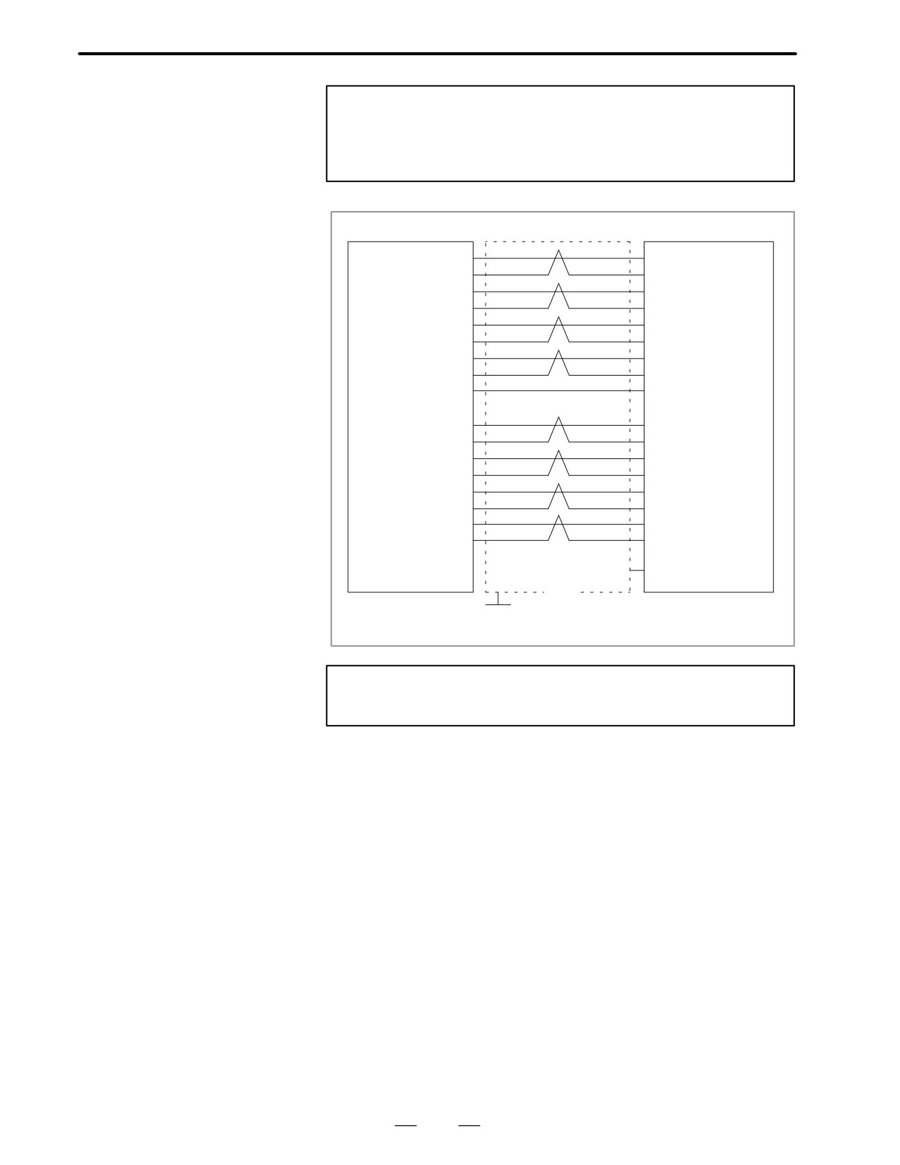
Notes
1
When CS is not used, connect it to RS.
2
For protocol A or extended protocol A: When DR is not used,
connect it to ER. Always connect CD to ER.
R422-1(JD6A)
Host computer
RD (01)
(04) RD
*RD (02)
(22) *RD
RT (03)
(17) TT
*RT (04)
(35) *TT
CS (05)
(07) RS
*CS (06)
(25) *RS
DM (07)
(12) TR
Note) *DM (09)
(30) *TR
0V (08)
(19) SG
(+24V) (10)
SD (11)
(06) RD
*SD (12)
(24) *RD
TT (13)
(08) RT
*TT (14)
(26) *RT
RS (15)
(09) CS
*RS (16)
(27) *CS
TR (17)
(11) DM
*TR (18)
(29) *DM
(+24V) (19)
(20)
(01) FG
Shield
G
Connector : Half-pitch 20 pins (PCR)
Connector : D-SUB 25 pins
Note
Always use a twisted pair cable.
334
B-62445E/03
8.TROUBLESHOOTING
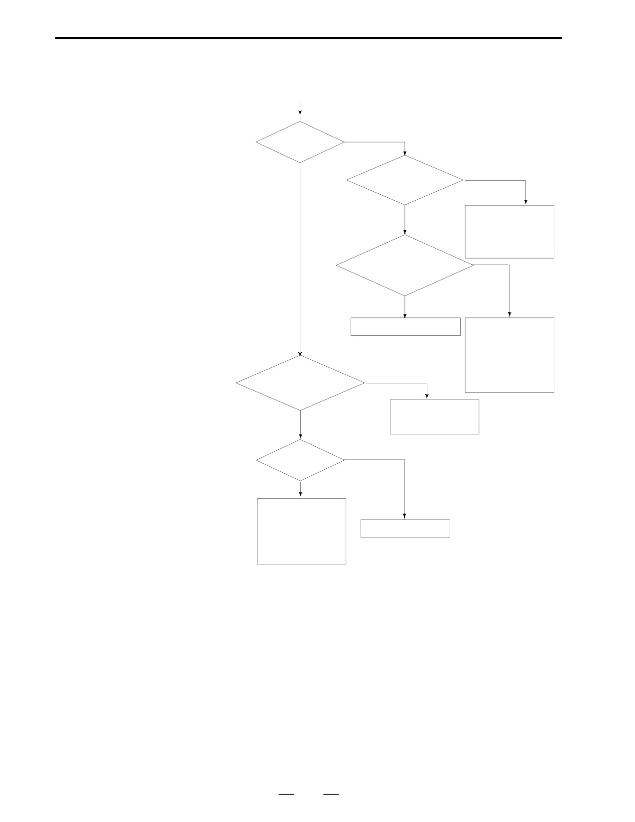
8.10
REFERENCE
(START)
POSITION DEVIATES
YES
By 1 grid ?
NO
Length of de-
NO
celeration dog
sufficient ?
YES
Exchange dog.
As a temporary work,
lower rapid traverse
rate in reference posi-
tion return
Does deceleration sig-
nal *DECα change
between grids ?
YES
NO
Wrong mounting position
Limit switch for *DEC
a is faulty (variation is
large).
As a temporary work,
lower FL rate in refer-
ence position return.
Does machine return
NO
to original position by
power OFF ?
Confirm connection
YES
between servo mo-
tor and machine
OFF
Is 5V of pulse
coder correct ?
YES
· Pulse coder is
faulty
*Voltage drop be-
· Servo control
Confirm cable
module or servo
tween +5V and 0V
interface module
should be less than
is faulty.
0.2V
335
8. TROUBLESHOOTING
B-62445E/03
8.11
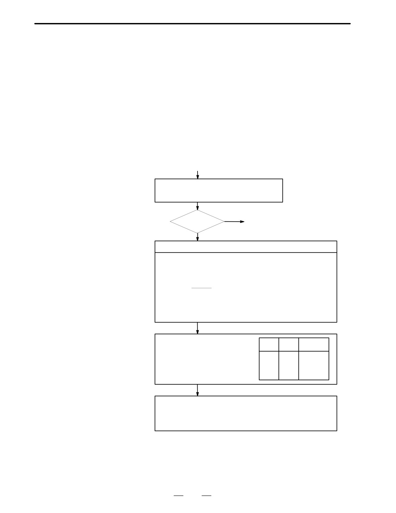
ALARM 90
(REFERENCE
POSITION RETURN IS
ABNORMAL)
Contents
Reference position return was executed when the following condition is
not satisfied:
The CNC received one rotation signal at least one time when the axis is
moving to the reference position at a speed higher than a speed equivalent
to 128 pulses of position error amount(DGN300).
Countermeasures
(START)
Position error
Check whether position gain is greater than 128 pulses
amount : 300
(DGN 300) before or during reference position return.
YES
128 or
(1) Next page
more
NO
Raise the speed
Check feed rate command:
PRM 1420 F : Rapid traverse rate
(mm/min)
PRM 1424
Manual rapid traverse rate (mm/min)
PRM 1825 G : Servo loop gain
(0.01sec-1)
F
5000/3
Position error=
G detection unit[µm/PLUSE]
Detection unit : Move amount to a command pulse (usually 1µm)
In metric machine, if the no. of digits below decimal point is 4 on the
position display screen, detection unit is 0.1 mm.
Check rapid traverse override signals :
Override
ROV1
ROV2
ROV1
DGN
014.0
1014.0 (For TT series)
0
0
100%
ROV2
DGN
014.1
0
1
50%
1014.1 (For TT series)
1
0
25%
PRM
1421
Fo rate
1
1
Fo rate
Check reference position return deceleration signal
DEC1 DEC8 DGN 009.0 ∼ 009.7
When reference position return is started from deceleration signal 0, feed rate
becomes FL rate.
PRM 1425 FL rate
336
B-62445E/03
8.TROUBLESHOOTING
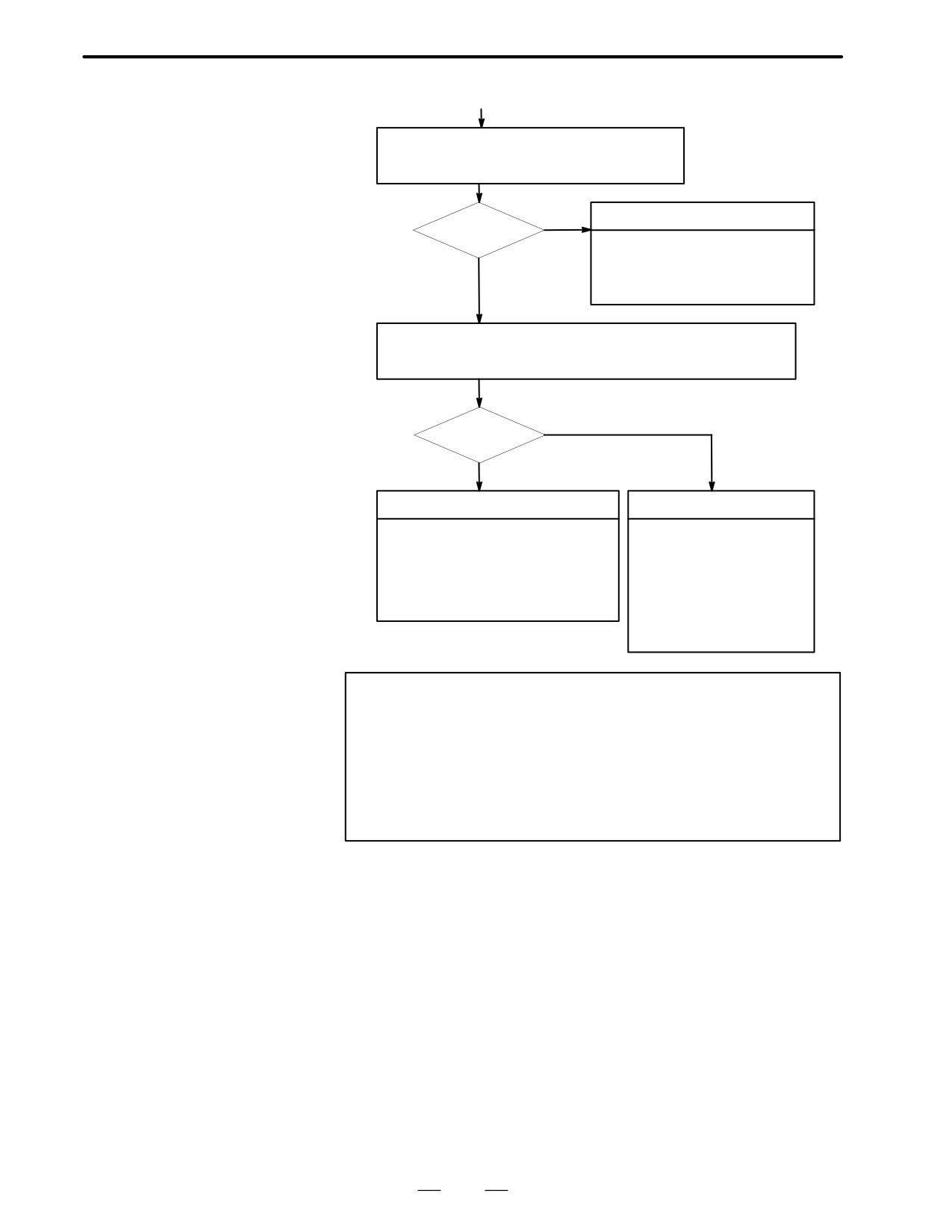
(1)
Check whether the motor ratated more than one rotation
(one rotation signal is issued ) at faster than 128 pulses
of position error amount.
NO
Return start position is too close
Rotated ?
· Chagne the return start position.
· Move the machine at faster that 128
YES
pulses for more than one rotation to
wards RP.
Check that voltage of pulse coder is higher than 4.75 V.
To measure pulse coder voltage, remove the motor cover and measure on
pulse coder PCB at across + and - or +5V and 0V terminals.
NO
More than 4.75V
YES
Hardware failure
Pulse coder power voltage is low
· Pulse coder is faulty
· Caused by wire resistance
Change pulse coder or motor
check wire material
· Main CPU board is faulty
(resistance shall be 0.5W or
Change main CPU board
less in both ways to restrict
· Option 2 board is faulty
voltage drop.)
Change option 2 board
· Pulse coder power supply is
abnormal
Change the power supply .
Notes
1
After the pulse coder or motor is exchanged, reference
position or machine’s standard point may be different from
former one. Please set it correctly.
2
When the main board is exchanged, all the data stored in
memory is lost. Reset all the NC data again, referring to the
data input/output item.
D Reference
A speed more than 128 pulses is required because if speed is lower that
this, one-rotation signal does not function stably, causing improper
position detection.
337
8. TROUBLESHOOTING
B-62445E/03
Absolute position data in the serial pulse coder was lost.
8.12
(This alarm will be generated when serial pulse coder is exchanged or
ALARM 300
position feedback signal cable of the serial pulse coder is disconnected).
(REQUEST FOR
REFERENCE
POSITION RETURN)
Remedies
Machine position must be memorized using the following method:
D When reference position
(1) Execute manual reference position return only for an axis for which
return function is
this alarm was generated.When manual reference position return
present
cannot be executed because of an another alarm, set parameter 1815#5
to 0 and release the alarm and perform manual operation.
(2) Press RESET key at the end of reference position return to release the
alarm.
D When reference position
Execute dogless reference position setting to memorize the reference
return function is not
position.
present
D When serial pulse coder
Since the reference position is different from the former one, change the
is changed
grid shift value (PRM 1850) to correct the position.
Related parameters
#7
#6
#5
#4
#3
#2
#1
#0
1815
APC x
APZx
#5(APCx)
0 : Position detector is incremental pulse coder.
1 : Position detector is absolute pulse coder.
#4(APZx)
Reference position of absolute pulse coder is :
0 : not established
1 : established
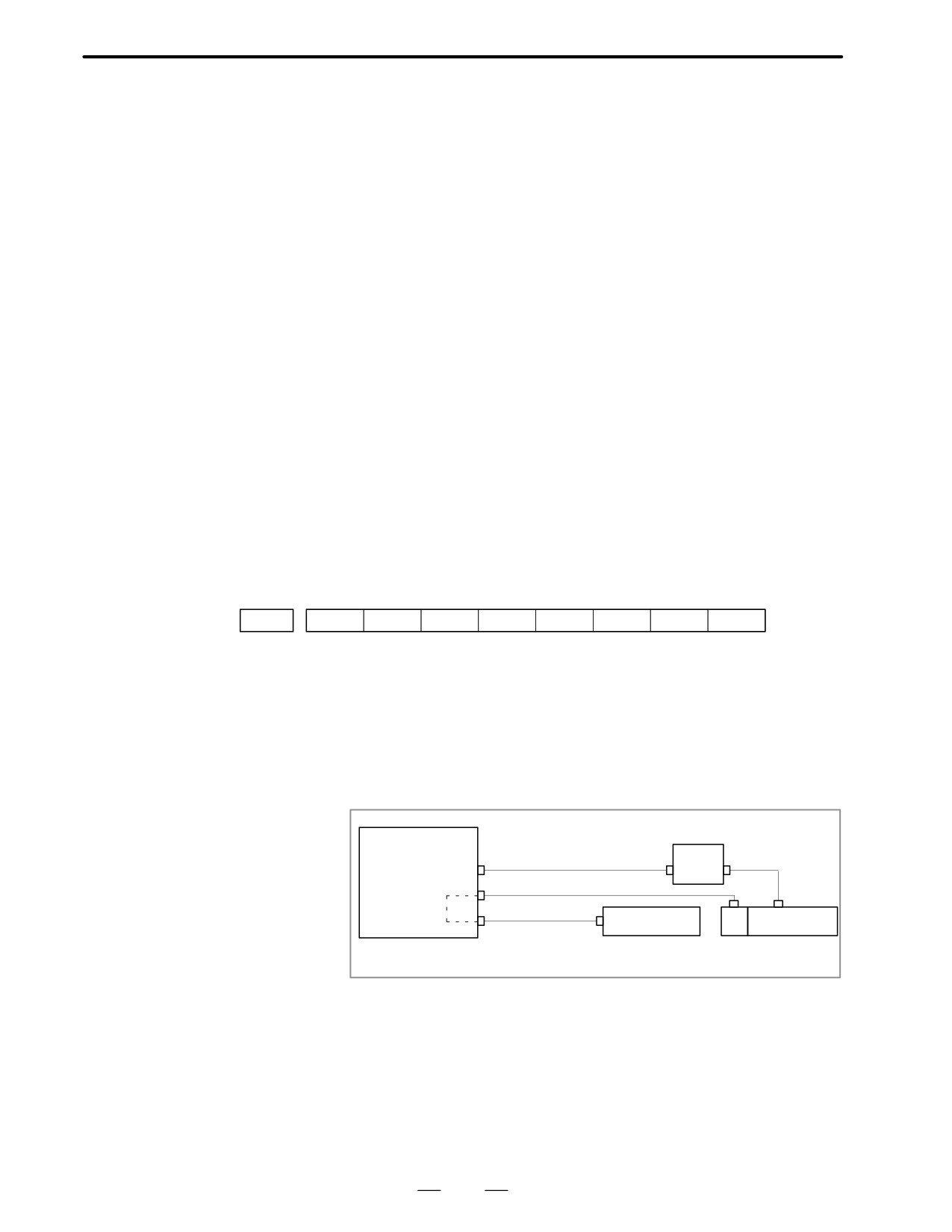
System configuration
Main CPU board
or option 2 board
PWM signal
Servo
Power cable
AMPx
amp.
ENCx
Feedback signal
APCBAT
Battery unit 6V
PC
Servo motor
PC : pulse coder
338
B-62445E/03
8.TROUBLESHOOTING
Absolute pulse coder, cable or servo module is faulty.
8.13
ALARM 301 TO 305
(ABSOLUTE PULSE
CODER IS FAULTY)
Countermeasures
1
Agitate the absolute pulse coder cable connected to the main CPU
board. If an alarm is issued, replace the cable.
Series 16 main CPU board (MAIN-A): JF1 to JF4
Series 16 main CPU board (MAIN-B): JS1A to JS6A
Series 18 main CPU board: JS1A to JS6A
2
Agitate the absolute pulse coder cable connected to the option 2 board.
If an alarm is issued, replace the cable.
Series 16 option 2 board (MAIN-A specification): JF5 to JF8
Series 16 option 2 board (MAIN-B specification): JS1A-2 to JS6A-2
Series 18 option 2 board: JS1A-2 to JS6A-2
3
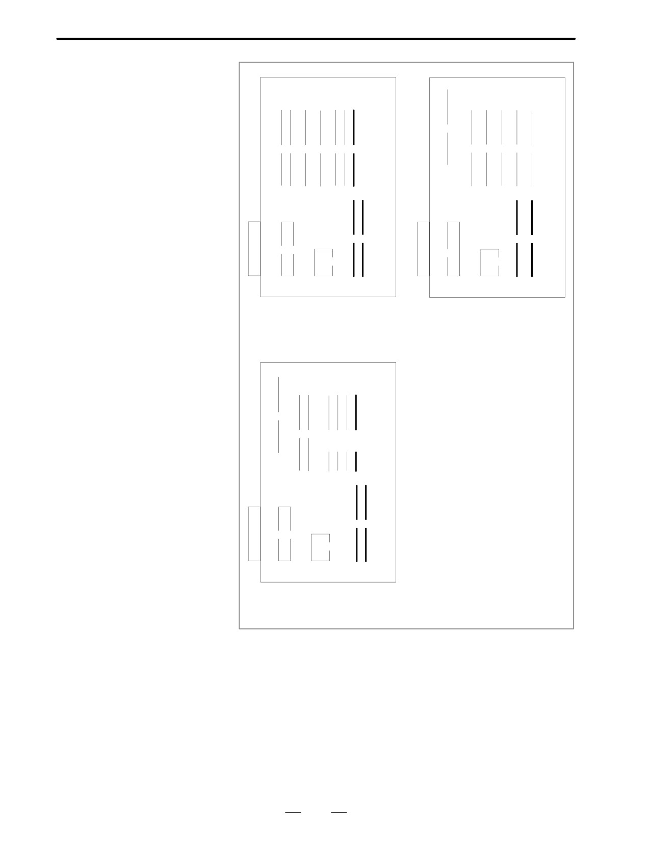
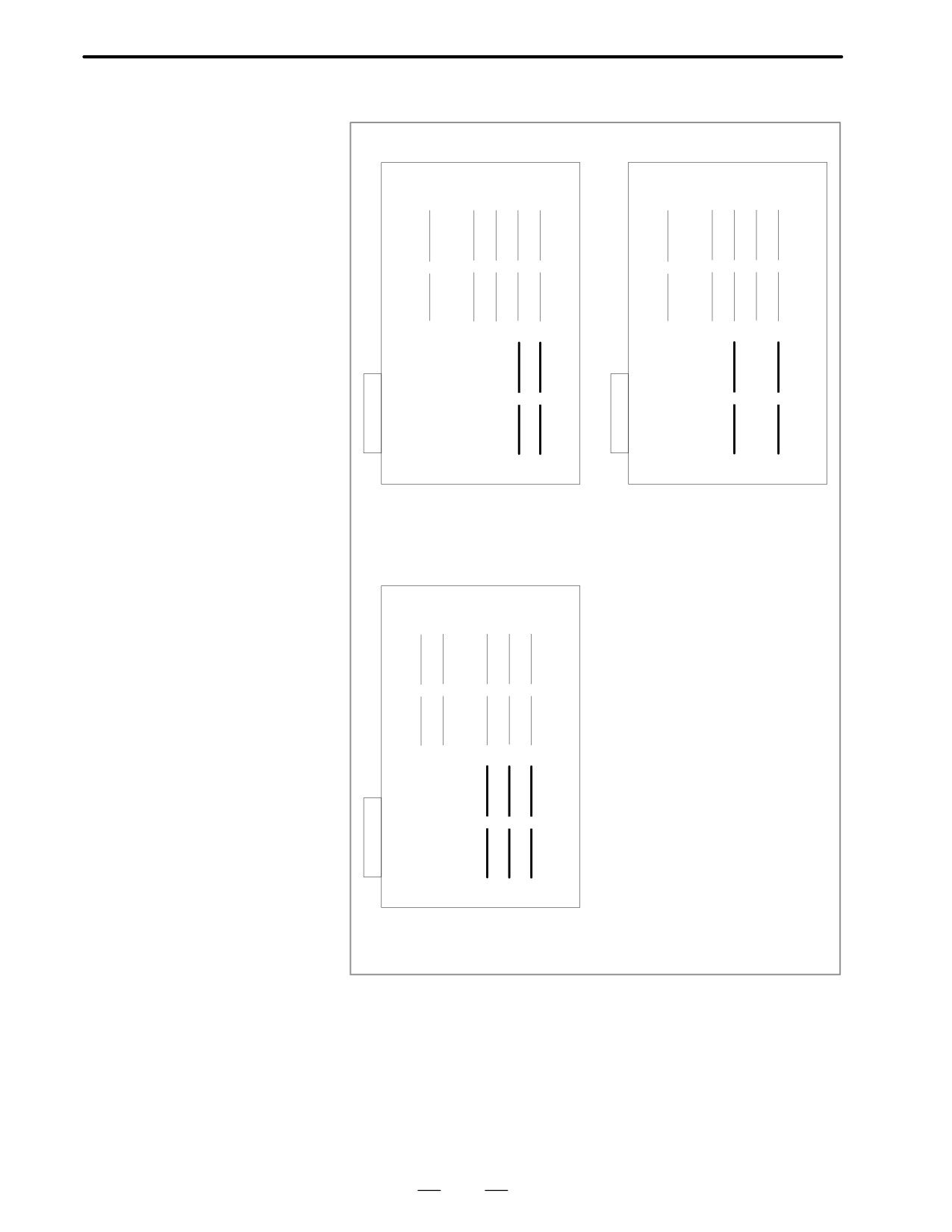
Replace the servo module.
Replace the module corresponding to the axis indicated by the alarm,
as shown in the figure below.Servo module specification:
A20B-2902-0060 or A20B-2902-0061
<Location of servo module> Main CPU board
A16B-3200-0010
A16B-3200-0170
(1)
(1)
(2)
(3)
(4)
(5)
(2)
(3)
(4)
(5)
(6)
(6)
(7)
(7)
(8)
(8)
(9)
(9)
(10)
(7) Servo module of 1st, 2nd axis
(9) Servo module of 1st, 2nd axis
(6) Servo module of 3rd, 4th axis
(7) Servo module of 3rd, 4th axis
339
8. TROUBLESHOOTING
B-62445E/03
A16B-3200-0110
A16B-2202-0860
(1)
(1)(2)
(3)
(4)
(5)(6)
(7)
(2)
(3)
(4)
(5)
(6)
(8)(9)
(7)
(8)
(10)
(9)
(11)
(10)
(7) Servo module of 1st, 2nd axis
(8) Servo module of 1st, 2nd axis
(9) Servo module of 3rd, 4th axis
(7) Servo module of 3rd, 4th axis
(8) Servo module of 5th, 6th axis
A16B-3200-0160
(1)
(2)
(3)
(4) (5) (6)
(7)
(8)
(9)
(10)
(11)
(7) Servo module of 1st, 2nd axis
(9) Servo module of 3rd, 4th axis
(8) Servo module of 5th, 6th axis
340
B-62445E/03
8.TROUBLESHOOTING
<Location of servo module> Option 2 board
A16B-2202-0400, 0401
A16B-2202-0890, 0891
(1)
(2)
(3)
(4)
(5)
(1)
(2)
(3)
(4)
(5)
(6)
(7)
(6)
(7)
(7) Servo module of 5th, 6th axis
(7) Servo module of 5th, 6th axis
(6) Servo module of 7th, 8th axis
(6) Servo module of 7th, 8th axis
A16B-2202-0850, 0851, 0853
(1)
(2)
(3)
(4)
(5)
(6)
(7)
(8)
(6) Servo module of 5th, 6th axis
(7) Servo module of 3rd, 4th axis
(8) Servo module of 1st, 2nd axis
341
8. TROUBLESHOOTING
B-62445E/03
This alarm is generated when absolute pulse coder battery becomes low.
8.14
ALARM 306 TO 308
(ABSOLUTE PULSE
CODER BATTERY IS
LOW)
Remedies
Exchange the battery connected to the connector JA4A on the main CPU
board or the connector JA4B on the option 2 board.
Note
Change the batteries while power of NC is supplied.
Do not change the battery (memory backup battery) for the
control unit.
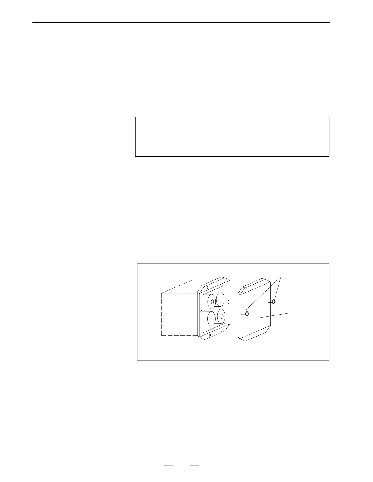
Replacing batteries for
1
Have 4 commercially available dry cell batteries ready.
separate absolute pulse
2
Turn on power of the machine.
coder
If the batteries are replaced with the power on, absolute position of the
machine is lost.
3
Loosen the screws of battery case lid and remove the lid.
Consult with the MTB’s manual for where the battery case is installed.
4
Replace the batteries in the case.
Take care to place the batteries facing in the correct direction. (Insert
the batteries as shown in the diagram with 2 facing one way and 2 the
other.)
Thread
Lid
Replacing Dry Cell Batteries
5
Having exchanged the batteries put the lid back on.
6
Turn off the power of the machine.
342
B-62445E/03
8.TROUBLESHOOTING
An error is generated in the control section of the serial pulse
8.15
coder.
ALARM 350 (SERIAL
PULSE CODER IS
ABNORMAL)
Points
1
Alarm No. 351 has also generated⇒Refer to alarm 351.
2
Only alarm No. 350 has generated⇒Refer to the following Confirm
the details by diagnostic number 0202 and 0204.
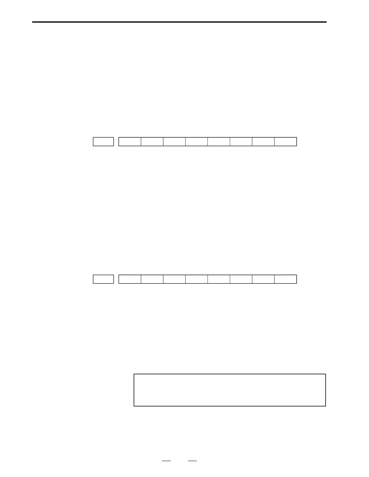
D When diagnostic number
0202 shows 1
#7
#6
#5
#4
#3
#2
#1
#0
0202
CSA
PHA
RCA
CKA
SPH
DGN
#6(CSA)
Check sum alarm has generated.
#4(PHA)
Phase data abnormal alarm has generated.
#3(RCA)
Speed count abnormal alarm has generated.
#1(CKA)
Clock alarm has generated.
#0(SPH)
Soft phase data abnormal alarm has generated.
1
Check the contens using the above diagnostic function if the alarm
generates repeatedly. If diagnostic data is the same, serial pulse coder
may be faulty.⇒Refer to Notes
2
When diagnostic result does not the same, or other abnormality is
detected, an external noise may be generated.
D When diagnostic number
0204 shows 1
#7
#6
#5
#4
#3
#2
#1
#0
0204
LDA
PMS
DGN
#4(LDA)
LED of serial pulse coder is abnormal
#3(PMS)
Pulses are not issued correctly by abnormality of serial pulse coder C or
feedback cable.
(1) #4(LDA): LED in the serial pulse coder is abnormal.
Serial pulse coder is faulty⇒Refer to Notes
(2) #3(PMS): Pulses are not issued correctly by abnormality of
feedback cable.
1
Fault of serial pulse coder ⇒Refer to Notes
2
Feedback cable is faulty.
Note
Reference position and machine’s standard position are
different from the ones before, adjust and set them correctly.
343
8. TROUBLESHOOTING
B-62445E/03
An error is generated in communication with serial pulse coder.
8.16
ALARM 351 (SERIAL
PULSE CODER
COMMUNICATION
IS ABNORMAL)
Points
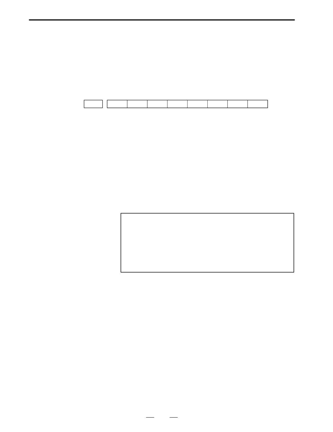
Check the details by the diagnostic function of the CNC.
#7
#6
#5
#4
#3
#2
#1
#0
0202
CSA
PHA
RCA
CKA
SPH
DGN
#7(DTE)
Data error has generated.
#6(CRC)
Serial communication error has generated.
#5(STB)
Stop bit error has generated.
1) #7(DTE):Response from serial pulse coder is absent.
Causes
1
Signal cable is disconnected
2
Serial pulse coder is faulty. å See note 1.
3
+5V to the serial pulse coder is lowered.
2) #6(CRC),#5(STB):Serial communication is in faulty
1 Signal cable is disconnected.
2 Serial pulse coder is faulty å See Note 1.
3 Main CPU board or Option 2 board is faulty å See Note 2
Notes
1
After the serial pulse coder is changed, reference position
or machine’s standard point is different from the one before
replacement. Therefore reset and adjust it again.
2
All the data stored in memory is lost when the main board
is changed. Set NC data again, referring to “chapter 3 data
input/output”.
344
B-62445E/03
8.TROUBLESHOOTING
Amplifier or overheat of motor is detected.
8.17
ALARM 400
(OVERLOAD)
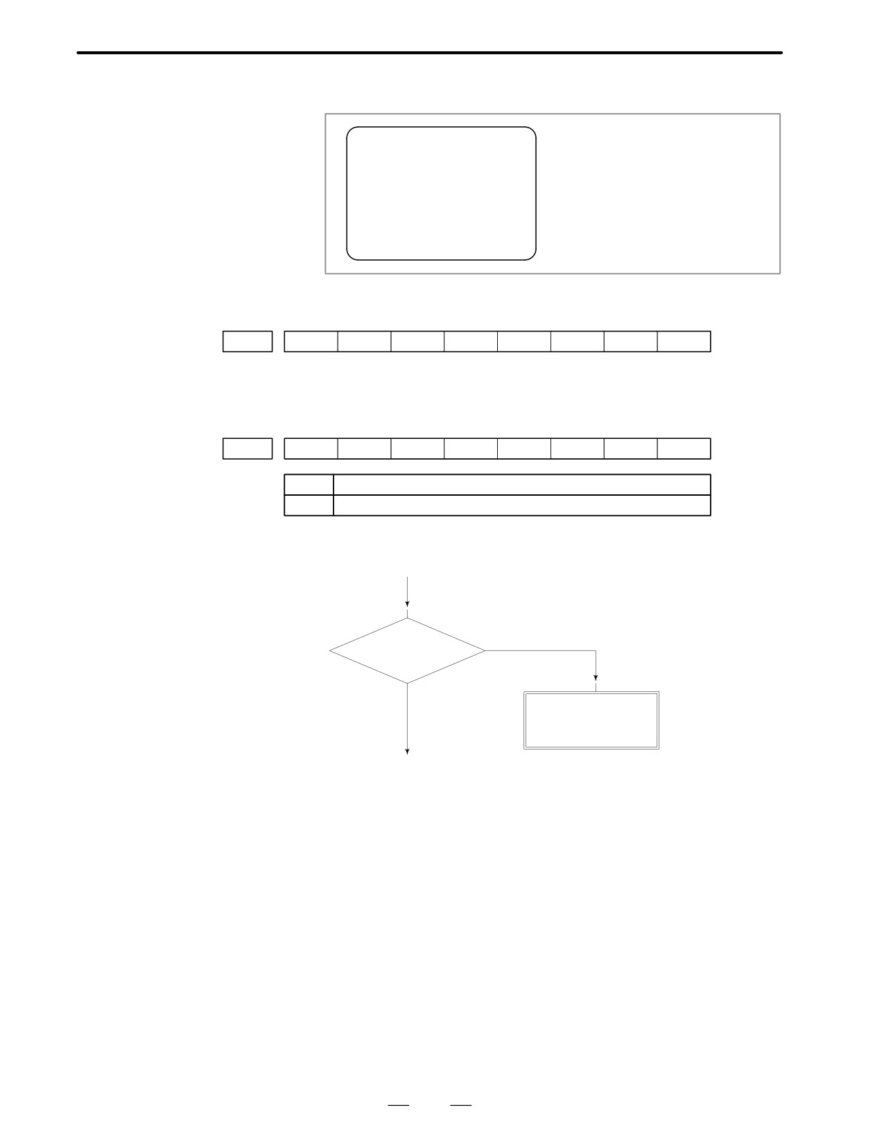
400 SERVO ALM :X OVERLOAD
⇐ Example of CRT display.
Axis name is also displayed.
Points
Confirm the detail by the diagnostic function of CNC.
#7
#6
#5
#4
#3
#2
#1
#0
0200
OVL
DGN
#7(OVL): 1 OVERLOAD ALARM is displayed.
Check details of alarms by DGN 201.
#7
#6
#5
#4
#3
#2
#1
#0
0201
ALD
DGN
↓
1
Overheat of servo motor
0
Overheat of servo amplifier
Overheat of servo motor
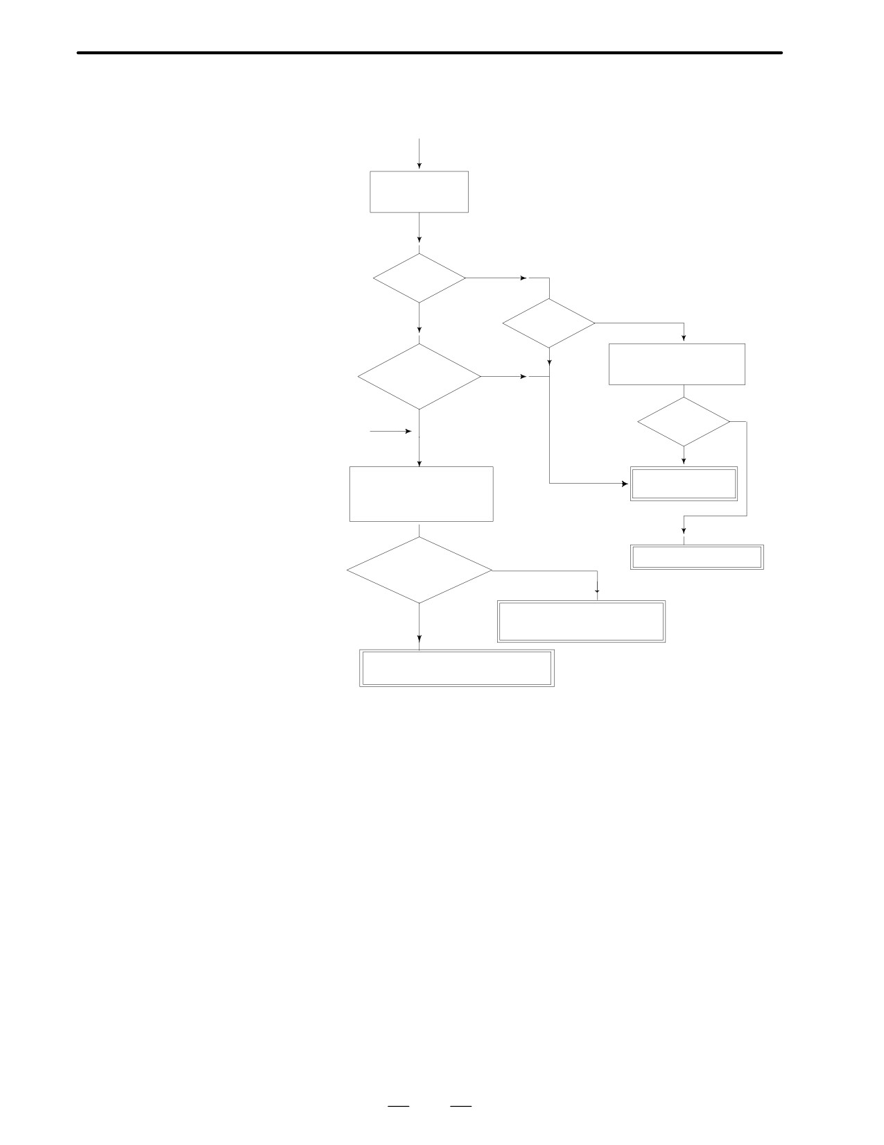
(START)
NO
Is it hot ?
YES
Overheat of motor
Defective thermostat
NOTE : After the motor is changed, reference
(Next page) (1)
position or machine’s reference point is
different from the one before replace
ment. Set it again.
345
8. TROUBLESHOOTING
B-62445E/03
D Overheat of servo
LED 6 of servo amplifier is lit
amplifier
(START)
Check LED status
of servo amplifier
NO
[6] ?
YES
NO(Not light)
[-] ?
YES
Check input power volt-
NO
age of servo amplifier
Is amplifier hot
?
NO
YES
Normal ?
(1)
<From previous page>
YES
Measure current at ter-
Servo amplifier is
minal IR and IS while
faulty
moving the machine.
*Refer to item of C series
servo amp.
NO
Check magnetic circuit
Does current ex-
ceed a rated one
?
· Check temperature around
YES
· Lower cutting conditions
Machine load is large
Insulation of motor is poor
346
B-62445E/03
8.TROUBLESHOOTING
Ready signal (*DRDY) of servo amplifier is not turned on or turned off
8.18
during operation.
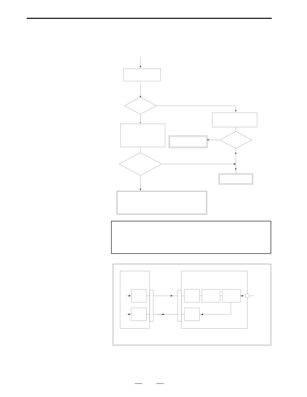
ALARM 401 (*DRDY
SIGNAL TURNED
(START)
OFF)
*When alarm 414 is also generated, LED
shows a number. Consult with alarm 414.
Check LED status
of servo amplifier
NO(Not lit)
[-] ?
YES
Check input power sup-
ply of servo amplifier
Check if 100VAC is
supplied across 5 and 6
on terminal board T1 of
YES
Servo amp. is
Normal ?
the servo unit
faulty
NO
NO
100VAC is
normal ?
YES
Check magnetics
circuit
· Cable disconnection between servo amp. and
main CPU or option 2 board.
· Servo amp. is faulty
· Main CPU board or option 2 board is faulty
Note
When the main CPU board is replaced, all the data stored
in memory is lost. Set NC data again, referring to chapter 3.
“Data input/output” .
Main CPU board
Servo amplifier (C series)
Option 2 board
AMPx
CN1
T1-5, 6
-10
-10
DV
RV
RLY
MCC
AC
*MCOM
100V
-20
-20
RV
DV
*DRDY
From 1st axis to 4th axis are main CPU board. 5th axis or
later are option 2 board.
347
8. TROUBLESHOOTING
B-62445E/03
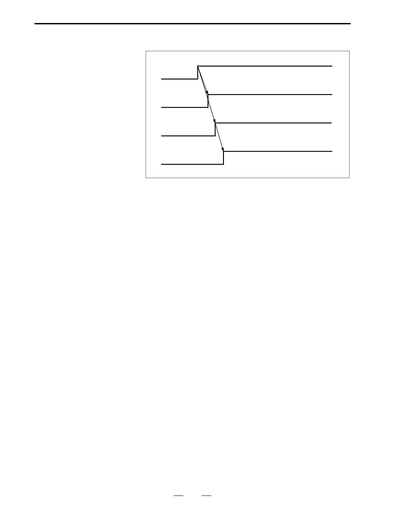
Power on sequence (NCàServo amplifier)
=
*Power supply unit failure
Power ON
*Input fuse disconnection
=
*SVF1~8 (Servo off signal)
Servo enable
Position, velocity
=
*System alarm (ALM900∼973) *Servo alarm
control ready (*MCON)
(ALM400∼417) *Emergency stop (*ESP)
Servo amp. ready (DRDY)
=
* Servo amp. alarm (1-9,b) *Emergency
stop signall (*ESP) *100VAC Lack of
3-phase input voltage
348
B-62445E/03
8.TROUBLESHOOTING
8.19
ALARM 404 AND 405
(*DRDY SIGNAL
TURNED ON)
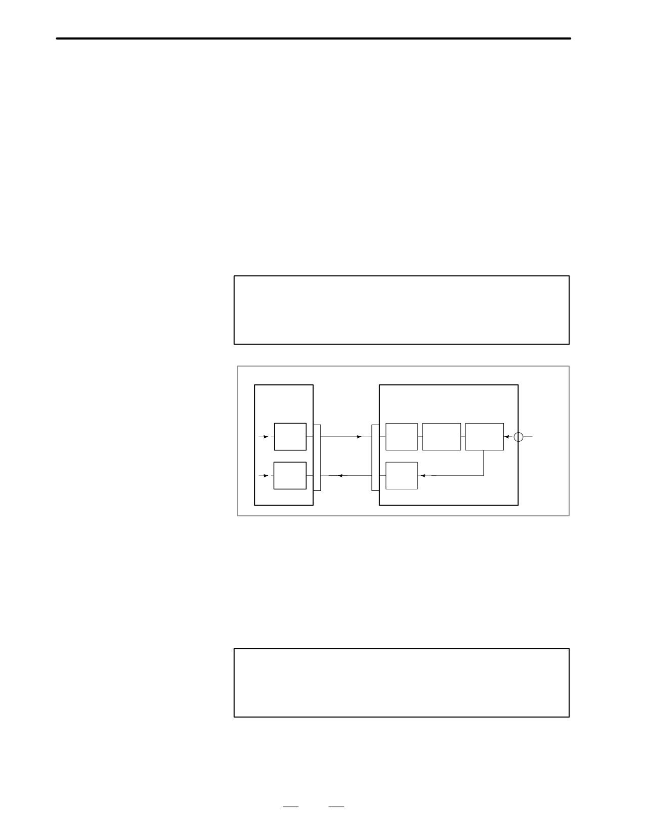
D Alarm 404
DRDY signal is turned on before MCON signal is turned on. Or DRDY
is not turned off after MCON signal is turned off.
D Causes
1
Servo amplifier is faulty.
2
Between servo amplifier and main CPU or between servo amplifier
and option 2 board is faulty.
3
Main CPU or option 2 board is faulty.
Note
When the main CPU board is replaced, all the data stored
in memory is lost. Set the NC data again, referring to chapter
3 “data input/output”.
· Main CPU board
Servo amplifier (C series)
· Option 2 board
AMPx
CN1
T1-5, 6
-10
-10
DV
RV
RLY
MCC
100
MCOM
VAC
-20
-20
RV
DV
*DRDY
From 1st axis to 4th axis are main CPU board. 5th axis or later are option
2 board.
D Alarm 405 (Reference
The grid signal is not turned on when the automatic reference position
positin return is
return by G28 is completed.
abnormal)
D Causes
Main CPU board or Option 2 board is faulty.
Note
When the main CPU board is replaced, all the data stored
in memory is lost. Set the NC data again, referring to
chapter 3 “data input/output”.
349
8. TROUBLESHOOTING
B-62445E/03
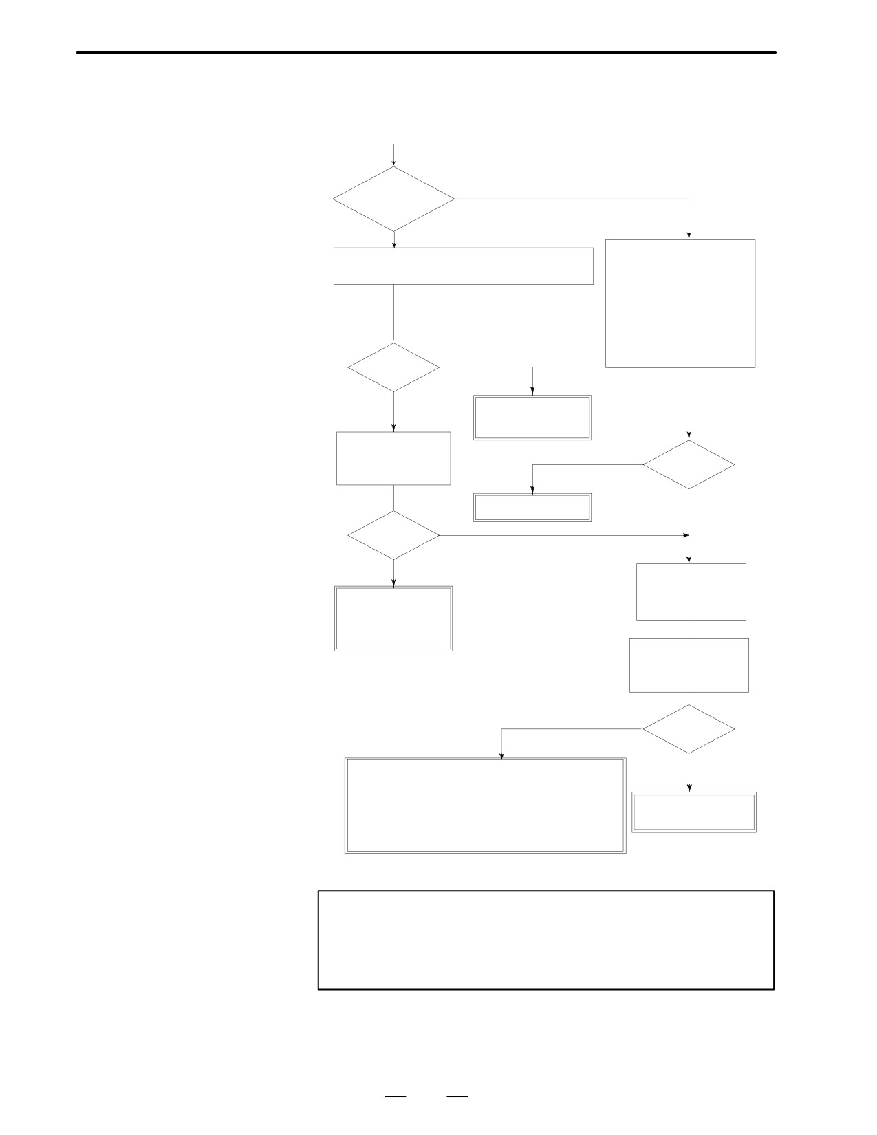
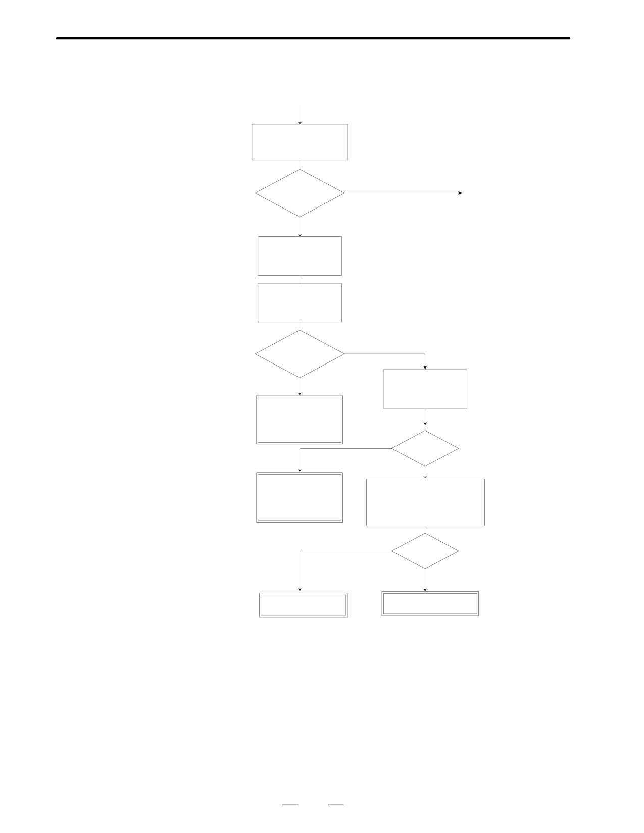
Position error amount at stop (DGN 300) exceeds a value set by parameter
8.20
No. 1829.
ALARM 410
(START)
(EXCESSIVE
POSITION ERROR
YES
Is it vertical
AMOUNT DURING
axis?
STOP)
NO
Check parameters 1825 and 1829 if they are cor-
Check servo off signal of
rect (see parameter list attached)
each axis. The servo off
function is valid when DGN
G126 bits 0-7 is 1.
Servo off funciton is used to
escape overload of an axis
when the axis is mechani-
cally clamped.
NO
Correct
?
YES
Set correct
Note)
parameters.
Perform initial setting
of servo parameters
YES
'1'?
NO
Check PMC
Recovered ?
NO
YES
Turn off NC power
Be carefull vertical
and remove power
axis does not drop.
line of motor then
Set digital servo pa-
rameters according
turn on power
to parameter list
Measure motor power
Note) Save current CNC pa-
at terminal board T1
Measure in DC range
9-10-11 of the servo
rameters in a floppy disk or
such before performing ini-
amplifier
tial setting for safety.
( No power ) ON
Power sup-
plied?
YES
· Servo amp. is faulty.
· Signal line disconnection between servo amp.
and main CPU or between servo amp. and
Motor power line
option 2 board.
is broken
· Main CPU board or option 2 board is
faulty.
Note
When the main board is replaced, all the data stored in
memory is lost. Set NC data again, referring to chapter 3
“data input/output” .
350
B-62445E/03
8.TROUBLESHOOTING
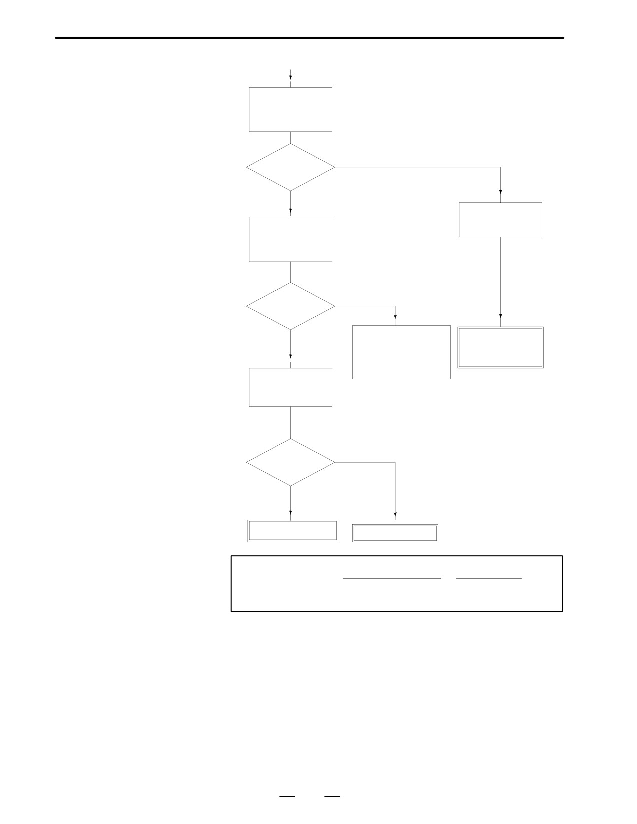
Position error amount during movement (DGN 300) execeeds a value set
8.21
by parameter 1828.
ALRAM 411
(START)
(EXECESSIVE
POSITION ERROR
With a move command,
DURING MOVE)
does this alarm occur af-
ter machine moves ?
YES (Move)
Moves and
(1)
alarmed?
NO (No move)
Turn off NC power,
remove power line
Be careful that vertical axis
and turn on power
does not drop by its weight.
Check motor power
at terminal board T1
9-10-11 of servo
Measure by DC voltage
amplifier
NO (Not output)
Power out-
put ?
YES
Confirm each-axis
servo off signal
G126.0∼7=1
Mechanical load is
excessive
Disconnection of
power line
YES
’1’ ?
NO
Check PMC su-
Signal line between main
quence, release ser-
CPU board or option 2
vo off and check op-
board and servo amplifier is
eration again
disconnected
From 1st axis to 4th
YES
axis are main CPU
Normal ?
board.
5th axis or later are
NO
option 2 board.
Servo amplifier is
Cable is faulty
faulty
351
8. TROUBLESHOOTING
B-62445E/03
(1)
Move the machine
at constant low
speed and check
DGN 300.
YES
Value fluctuate ?
NO
Measure current at
IR and IS while mov-
Compare the value
Note 1)
ing the machine
obtained by the fol-
lowing formula and
DGN 300
* Refer to C series servo
amplifier for current val-
ues
NO
Correct ?
YES
Servo amplifier is
Mechanical load is
faulty.
large. Refer to
Main CPU board or op-
alarm 400.
tion 2 board is faulty.
Compare value of
PRM1828 and the
list Note2)
From 1st axis to 4th axis are main CPU board.
5th axis or later are option 2 board.
Note) When the main CPU board is
replaced, all the data in
NO
memory is lost. Reset NC
Correct ?
data, referring to chapter 3
data input/output item.
YES
Servo amplifier is
faulty
Correct parameters
Notes
Feed rate (mmńmin)
1
1
Position error=
60 PRM1825
Detection unit
2
Parameter 1828yPosition error at rapid traverse
1.2
352
B-62445E/03
8.TROUBLESHOOTING
8.22
ALARM 414 (DIGITAL
SERVO SYSTEM IS
EXAMPLE OF DISPLAY
414 SERVO ALARM:X-AXIS
ABNORMAL)
AXIS NAME DETECTED
DETECTION
IS DISPLAYED
SYSTEM ERROR
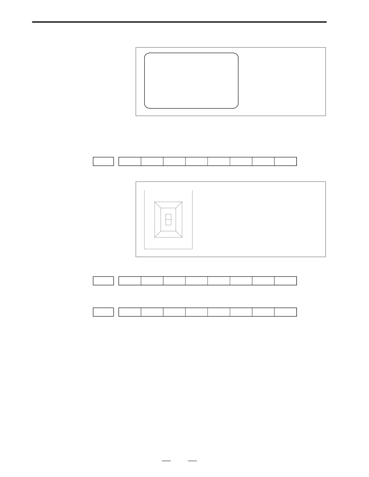
Points
Check details by CNC’s diagnostic fucntion and LED display on the servo
amplifier.
1
#7
#6
#5
#4
#3
#2
#1
#0
DGN
0200
LV
OVC
HCA
HVA
DCA
FBA
OFA
2
LED display on the servo amplifier
STATUS
* An alarm detected on the servo amplifier is
also displayed at DGN 200.
3
#7
#6
#5
#4
#3
#2
#1
#0
DGN
0204
OFS
MCC
D When DGN200 shows
”1”
#7
#6
#5
#4
#3
#2
#1
#0
DGN
0200
LV
OVC
HCA
HVA
DCA
FBA
OFA
#6(LV): Low voltage alarm
→ LED [2] or [3] lights
#5(OVC): Over current alarm
#4(HCA): Abnormal current alarm
³ LED [8] lights
#3(HVA): Over current alarm
³ LED [1] lights
#2(DCA): Discharge alarm
³ LED [4] or [5] lights
#1(FBA): Disconnection alarm
#0(OFA): Overflow alarm
353
8. TROUBLESHOOTING
B-62445E/03
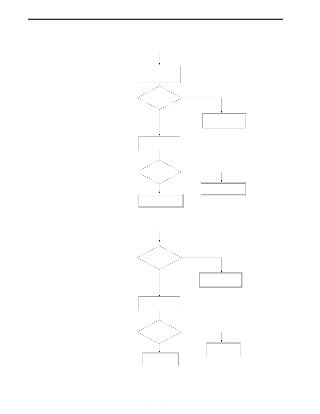
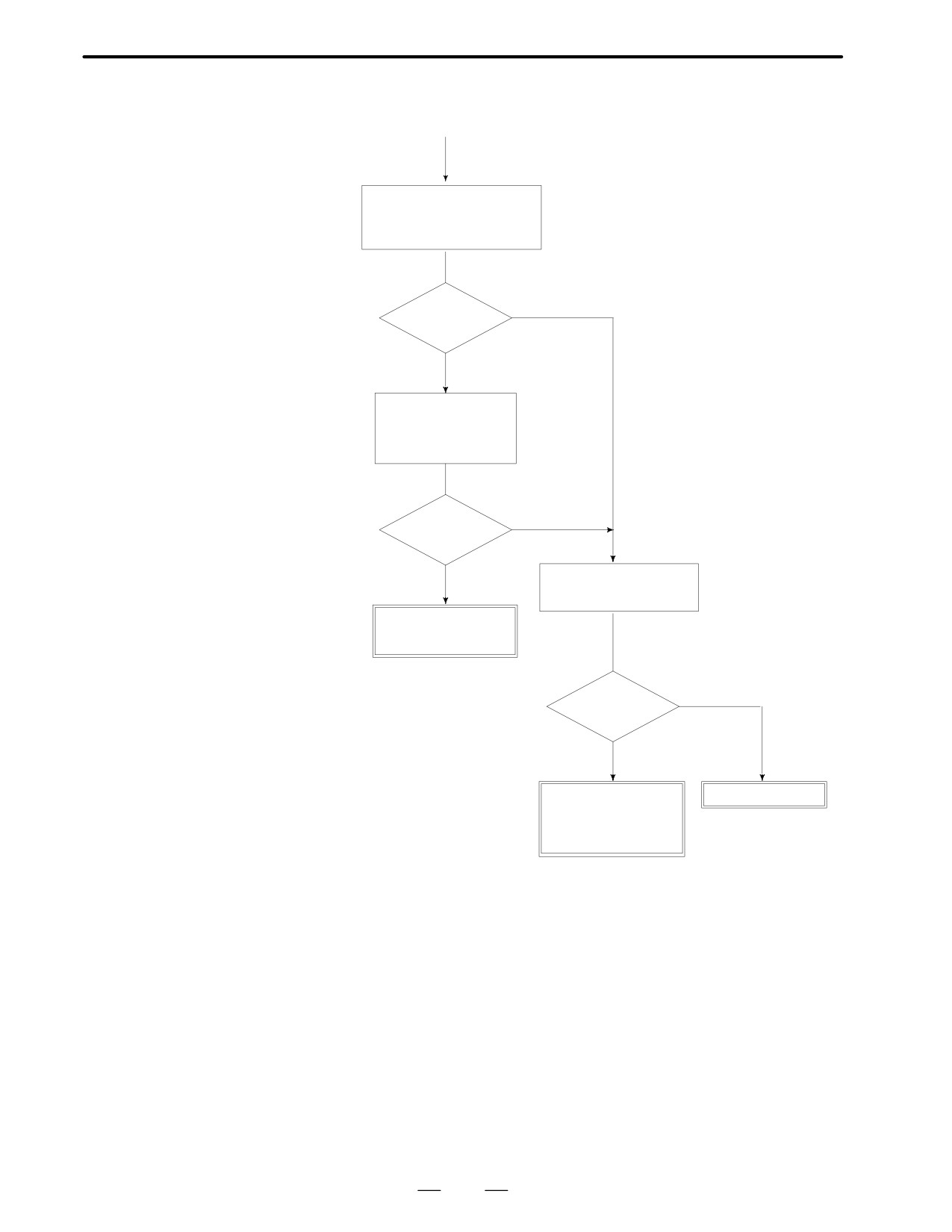
D #6(LV):Insufficient
voltage alarm
1
Servo amp LED [2] turns on (control power shortage)
(START)
Check +5V power
at check terminal of
servo unit
YES
Voltage is
normal ?
NO
Servo amplifier is
faulty
Check input power
* Power should be 200/220/230VAC -15%
to the controller
across terminal T1(13) and (14)
NO
Is voltage
normal ?
YES
Input voltage is
abnormal
Servo amplifier is
faulty
2
Servo amp LED [3] turns on (DC power shortage)
(START)
YES
Breaker off ?
NO
Turn off breaker and
check again
Check input volt-
* Power should be 200/220/230VAC,-15%
age of servo amp.
among terminal board T1(2)-(3)-(4).
Is voltage
NO
normal ?
YES
Input voltage
is abnormal
Servo amplifier
is faulty
354
B-62445E/03
8.TROUBLESHOOTING
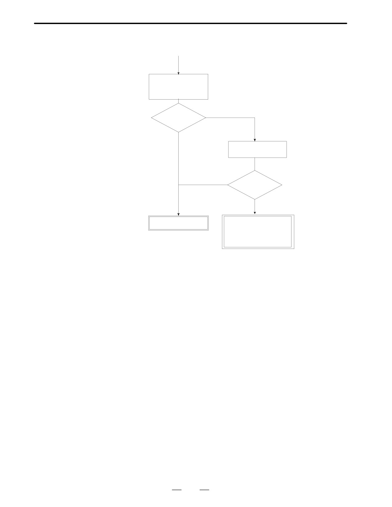
D #5(OVC):Over current
detection by software
(START)
Check current at check termi-
nal IR and IS at servo amplifi-
er and compare with rated
current of motor
Larger than
NO
1.7 times for motor 20S or
1.4 times ?
larger.
YES
Move axis at low speed
and measure current at
IR and IS, and compare
with rated current
Within rated
YES
current ?
NO
Check servo parameters
2040,2041,2056,2057 with
parameter list.
Machine load is
large. Check load
at machine side.
NO
Correct ?
YES
Correct parameters.
· Servo amplifier is
faulty
· Main CPU or option
2 board is faulty.
From 1st axis to 4th axis are main CPU board.
5th axis or later are option 2 board.
NOTE : When the main CUP board is
replaced, all the data in memory is
lost.Reset NC data, referring to
chapter 3 ”data input/output” .
355
8. TROUBLESHOOTING
B-62445E/03
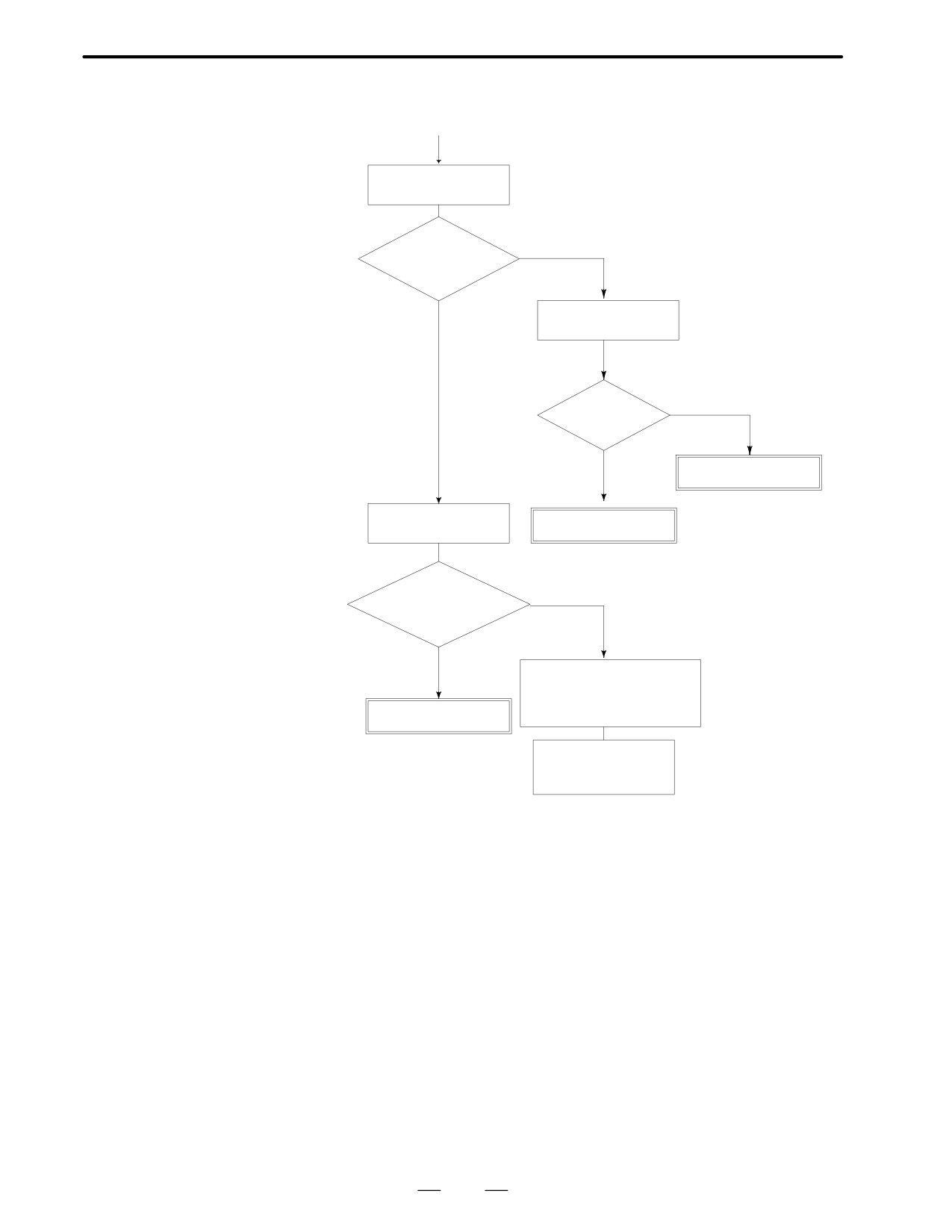
D #4(HCA):Abnormal
current alarm
(START)
(Servo amp. LED:[8]
lights)
Give a move command
and check wether the
alarm is generated
NO
Alarmed ?
YES
Remove motor power
* Take care that verti-
line and turn on power
cal axis may drop.
YES
Alarmed ?
NO
Servo amp. is faulty.
· Short circuit between
power lines
· Grounding of power lines
· Poor insulation of motor
356
B-62445E/03
8.TROUBLESHOOTING
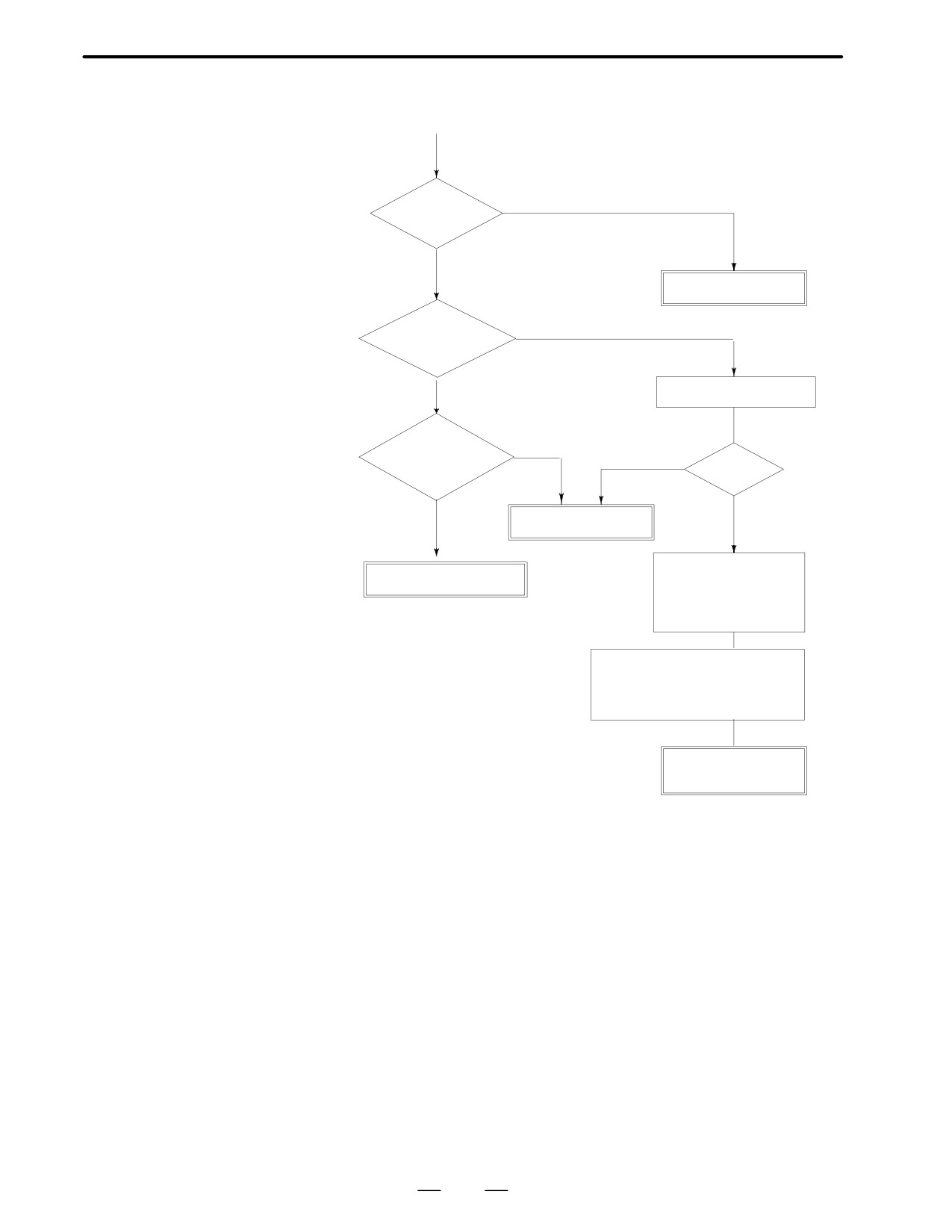
D #3(HVA):Over voltage
DC voltage in servo amp. is excessive.
alarm (Servo amp.LED
(Start)
[1] lights)
Confirm status when
an alarm is generated
Does the alarm
NO
generate during
deceleration ?
Power should be within
Confirm input voltage
200/220/230VAC among
YES
of servo amplifier
3 phases of terminal
T1(2),(3) and (4)
Is voltage
NO
normal ?
YES
Input power voltage
is abnormal
Check feed rate
Servo amp. is faulty
Does the alarm
YES
generate dur-
ing rapid tra-
verse ?
NO
· Is acc/dec time is correct ?
· Isn’t load inertial too large ?
· Is friction reduced by aging of
machine ?
Servo amp. is faulty
Set acc./dcc. time
Refer to acc./dec. param-
constant lager as a
eters 1600 and so on.
temporary measure
357
8. TROUBLESHOOTING
B-62445E/03
D #2(DCA):Discharge alarm
1
Servo amp LED 4 lights (discharge control circuit is abnormal)
(START)
Generate at
YES
power on ?
NO
Servo amp. is faulty
YES
Generate during
deceleration ?
NO.
Check frequency of
acceleration/deceleration
NO
Generate dur-
ing lowering of
NO
Frequent ?
vertical axis
YES
YES
Servo amp. is faulty
· Mechanical load inertia
Balancer adjustment failure
is large
· Resistance for friction
due to againg of machine
is reduced.
Check by motor load current
during up/down movement
Set a larger acc./dec. time constant
as a temporary measure.
*Take care that deceleration dis-
tance becomes longer.
Separate type dis-
charge resistor must
be added
358
B-62445E/03
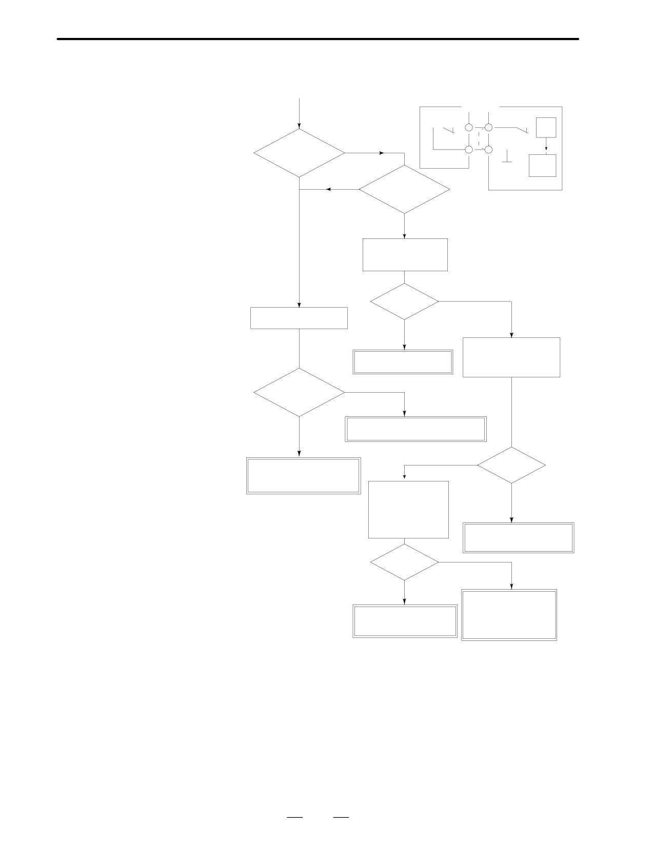
8.TROUBLESHOOTING
2
Servo amp LED 5 lights (discharge circuit overheat)
Separate type
(START)
Servo amp.
discharge unit
(C series)
T3
T1
TH -3
-15
TH
RV
YES
-4
-16
Generate at
power on?
0V
ALM
NO
YES
Is unit hot ?
Short betrween 15 and 16
when not used.
NO
Check resistance
across terminals
T1(15) and (16).
NO
0Ω ?
Measure load current
YES
Check whether sep-
arated discharge unit
Servo amp. is faulty.
is connected(Across
15 and 16 of T1)
Is larger than
NO
rated current ?
YES
· Check ambient temperature rise
· Lower cutting condition
(Wired across 15 and 16 or T1)
Wired ?
· Machine side load is large
YES
· Insulation of motor is poor
Measure reistance
NO
across 3 and 4 at
terminal board of
separate type dis-
charge unit.
Short-circuit across 15 and
16 of terminal board T1
YES
0Ω ?
NO
Disconnection of
cable between sep-
Separate type discharge
arate type dischrge
unit is faulty
unit and servo amp.
359
8. TROUBLESHOOTING
B-62445E/03
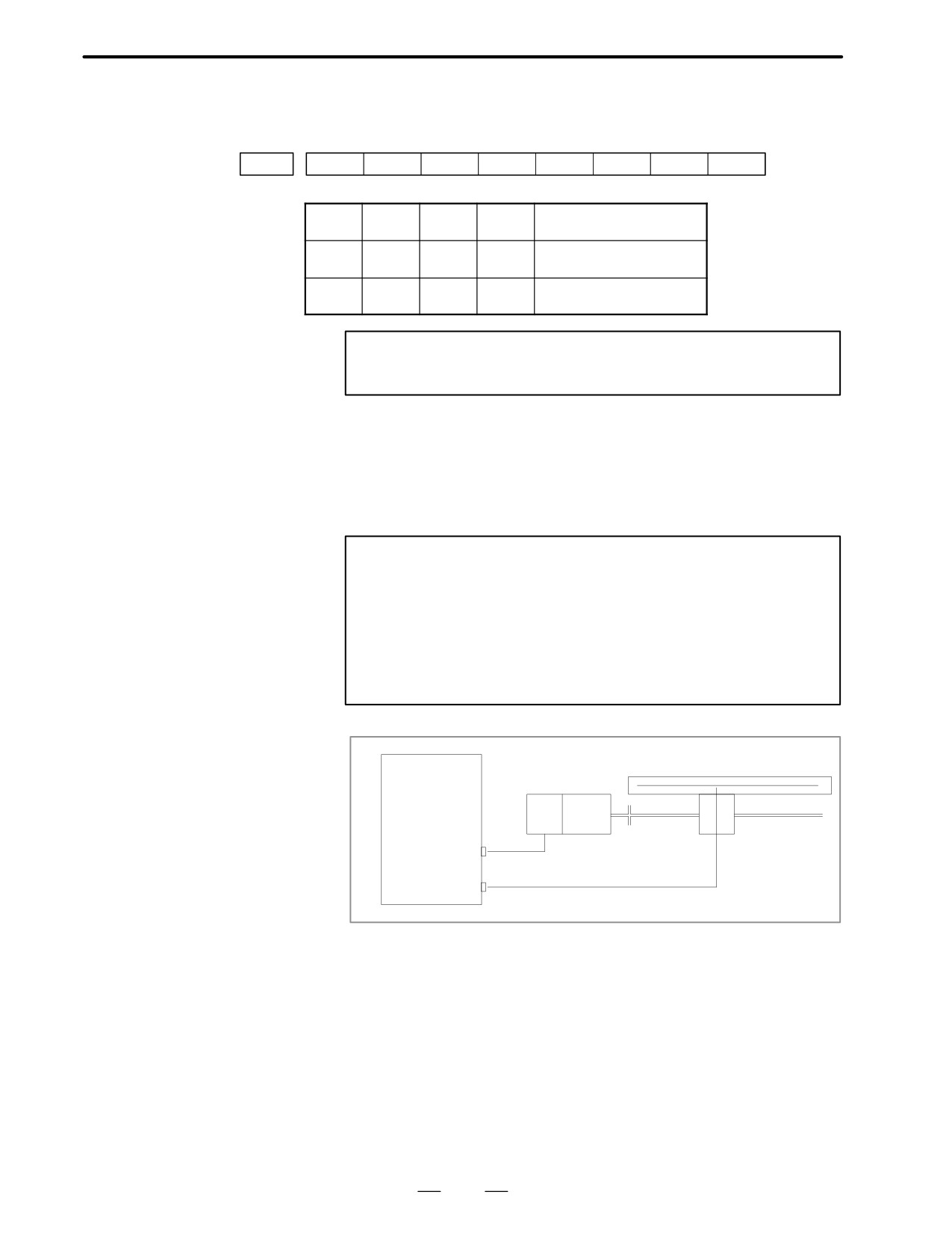
D #1(FBA):DISCONNECTIO
Position detection signal line is disconnected or short-circuited.
N ALARM
#7
#6
#5
#4
#3
#2
#1
#0
DGN
0201
ALD
EXP
→
→
1
-
-
0
Built-in serial pulse coder
³ENCX
disconnection
1
-
-
1
Separate type position
³SCALEX
detector connection
0
-
-
0
Pulse coder disconnec-
Note
tion (software)
Note
This alarm is related with full-closed system.
D Causes
1
Signal cable is disconnected or short-circuited
2
Serial pulse coder or position detector is faulty Refer to Notes 1
3
Main CPU board or option 2 board is faulty.
Refer to Notes 2
Notes
1
After the pulse coder is replaced, reference position or
machine’s standard position is different from former one.
Adjust and set it correctly.
2
When the main CPU board is replaced, all the data stored
in memory is lost. Set NC data again, referring to chapter 3
“data input/output”.
Linear scale
Main CPU board
or Option 2 board
PC
ENCx
SCALEx
x is an axis number
From 1st axis to 4th axis are main CPU board. 5th axis or later are
option 2 board.
7)#0(OFA):Overflow alarm
360
B-62445E/03
8.TROUBLESHOOTING
causes
1
Wrong setting of servo parameters 1800s.
2
Main CPU (1axis to 4 axes) or option 2 board (5 axes or more)
Note
When the main CPU board is replaced, all the data stored
in memory is lost. Set NC data again, referring to chapter
3 “data input/output ” .
When 1 is displayed at
DGN 204
#7
#6
#5
#4
#3
#2
#1
#0
DGN
0204
OFS
MCC
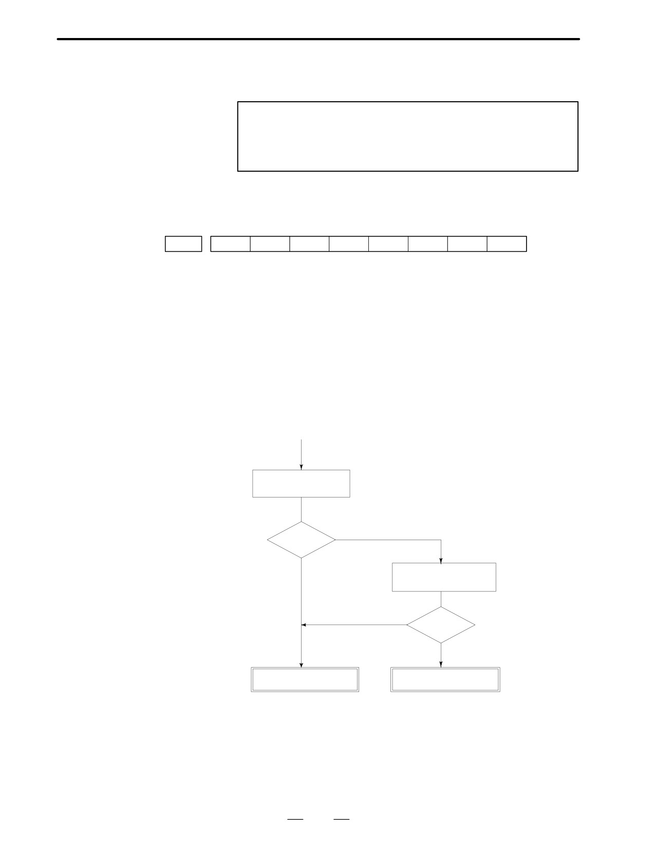
#6(OFS):
A/D converter used for current feedback in the digital servo is abnormal.
#5(MCC):
Contacts of electromagnetic contactor in the servo amp. is blown.→LED
7 lights.
Serial pulse coder C is an incremental pulse coder.
D #6(OFS):A/D converter is
Main CPU board or option 2 board is faulty
abnormal
When the main CPU board is replaced, all the data stored in memory is
lost.
Set NC data again, referring to chapter 3 ” data input/output ”.
D #5(MCC):Contacts of
electro-magnetic
(START)
contactor is blown within
servo amp.
Check LED of
servo amplifier
LED [7] Contacts of electro-magnetic
contactor is blown in servo
amplifier
NO (Not lit)
[7] ?
YES
Check input power
voltage of servo amp.
<Normal input power voltage>
AC200/220/2
YES
Correct?
30V
+10%,-15%
NO
Servo amplifier is faulty
Check magnetics circuit
361