FANUC Series 16 / 160 / 18 / 180 – Model B. Maintenance Manual - page 16
B-62445E/03
APPENDIX
B. ALARM LIST
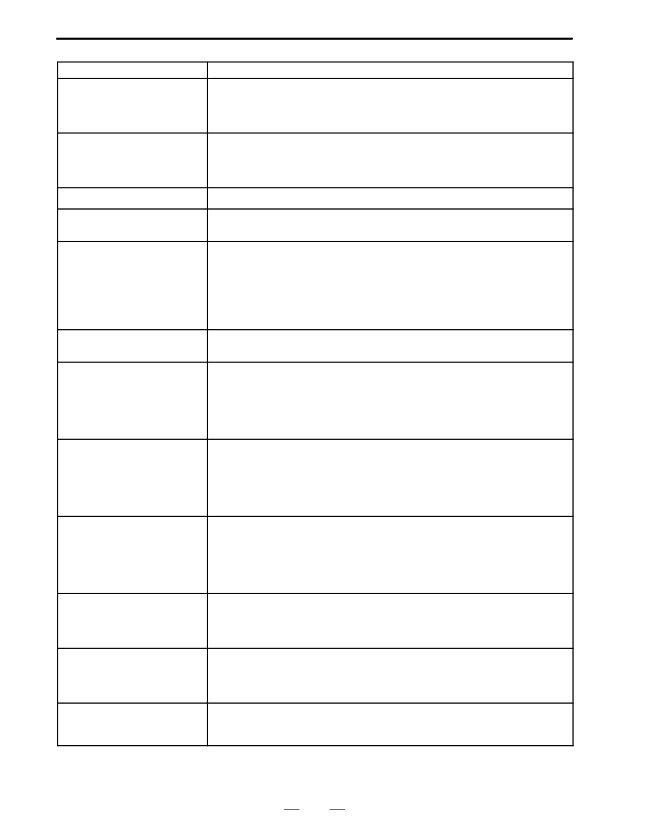
Message
Contents and solution
ER20 SYMBOL/COMMENT
Editing the symbol and comment was interrupted by the power off or by the switch to
DATA ERROR
the CNC screen by the function key etc.
(solution)
Please edit symbol and comment once on PMC.
Or, please input symbol and comment again.
ER21 MESSAGE DATA ERROR
Editing the message data was interrupted by the power off or the switch to the CNC
screen by the function key etc.
(solution)
Please edit message data once on PMC.
Or, please input message data again.
ER22 PROGRAM NOTHING
There is no sequence program
ER23 PLEASE TURN OFF
There is a change in setting LADDER MAX AREA SIZE etc.
POWER
(solution)
Please restart the system to make the change effective.
ER32 NO I/O DEVICE
Any DI/DO unit of I/O Unit or the connection unit etc. is not connected. When built-in
I/O card is connected, this message is not displayed.
(solution)
When built-in I/O card is used:
Please confirm whether the built-in I/O card is certainly connected with.
When I/O Link is used:
Please confirm whether the DI/DO units turning on. Or please confirm
the connection of the cable.
ER33 SLC ERROR
The LSI for I/O Link is defective.
(solution)
Please exchange the module of PMC engine.
ER34 SLC ERROR(xx)
The communication with the DI/DO units of the xx group failed.
(solution)
Please confirm the connection of the cable connected to the DI/DO
units of the xx group.
Please confirm whether the DI/DO units turned on earlier than CNC and
PMC. Or, please exchange the module of PMC engine on the DI/DO
units of the xx group
ER35 TOO MUCH OUTPUT
The number of the output data in the xx group exceeded the max. The data, which
DATA IN GROUP(xx)
exceed 32 bytes, become ineffective.
(solution)
Please refer to the following for the number of the data for each group.
“FANUC I/O Unit-MODEL A connecting and maintenance manual”
(B-61813E)
“FANUC I/O Unit-MODEL B connecting manual”(B-62163E)
ER36 TOO MUCH INPUT DATA
The number of the input data in the xx group exceeded the max. The data, which
IN GROUP(xx)
exceed 32 bytes, become ineffective.
(solution)
Please refer to the following for the number of the data for each group.
“FANUC I/O Unit-MODEL A connecting and maintenance manual”
(B-61813E)
“FANUC I/O Unit-MODEL B connecting manual”(B-62163E)
ER38 MAX SETTING OUTPUT
The assignment data for a group exceeds 128 bytes.
DATA OVER(xx)
(The assignment data of output side of xx group or later become ineffective.)
(solution)
Please reduce the assignment data to 128 bytes or less for the number
of the output data of each group.
ER39 MAX SETTING INPUT
The assignment data for a group exceeds 128 bytes.
DATA OVER(xx)
(The assignment data of input side of xx group or later become infective.)
(Solution) Please reduce the assignment data to 128 bytes or less for the number
of the input data of each goup.
WN01 LADDER MAX SIZE ER-
The MAX LADDER AREA SIZE in the system parameter is illegal.
ROR
(solution)
Set the correct value to MAX LADDER AREA SIZE and restart the
system.
*When ER00 to ER23 occur, sequence program is not available.
457
B. ALARM LIST
APPENDIX
B-62445E/03
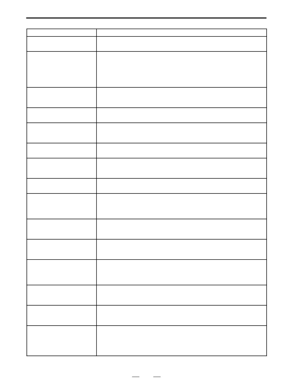
Message
Contents and solution
WN02 OPERATE PANEL AD-
The address setting data of the operator’s panel for FS-0 is illegal.
DRESS ERROR
(solution)
Please correct the address setting data.
WN03 ABORT NC-WINDOW/
LADDER was stopped while CNC and PMC were communicating.
EXIN
The functional instruction WINDR, WINDW, EXIN, DISPB, and etc. may not work
normally.
(solution)
When restarting the system, this alarm will be released. Execute the
sequence program(Press RUN key) after confirming whether there is a
problem in LADDER or not.
WN04 UNAVAIL EDIT MODULE
The LADDER editing module cannot be recognized.(PMC-RAx/RBxx=1 to 3)
(solution)
Please confirm the slot position installed.
Please confirm the installed module.
WN06 TASK STOPPED BY DE-
Some user tasks are stopped by break point of the debugging function.
BUG FUNC
WN07 LADDER SP ERROR
When functional instruction CALL(SUB65) or CALLU(SUB66) was executed, the
(STACK)
stack of the LADDER overflowed.
(solution)
Please reduce the nesting of the subprogram to 8 or less.
WN17 NO OPTION (LAN-
There is no C language option.
GUAGE)
WN18 ORIGIN ADDRESS ER-
The LANGUAGE ORIGIN address of the system parameter is wrong
ROR
(solution)
Please set the address of symbol RC_CTLB_INIT in the map file to the
LANGUAGE ORIGIN of the system parameter.
WN19 GDT ERROR(BASE,LIM-
The value of BASE, LIMIT or ENTRY of user defined GDT is illegal.
IT)
(solution)
Please correct the address in link control statement and build file.
WN20 COMMON MEM. COUNT
The number of common memories exceeds 8.
OVER
(solution)
Please reduce the number of common memories to 8 or less. It is
necessary to correct a link control statement,build file and the source file
for the common memory.
WN21 COMMON MEM. ENTRY
GDT ENTRY of the common memory is out of range.
ERROR
(solution)
Please correct the address of GDT ENTRY of the common memory in
the link control statement.
WN22 LADDER 3 PRIORITY
The priority of LADDER LEVEL 3 is out of range.
ERROR
(solution)
Please correct the value of LADDER LEVEL 3 in the link control
statement within the range of 0 or 10-99 or -1.
WN23 TASK COUNT OVER
The number of user tasks exceeds 16.
(solution)
Please confirm TASK COUNT in the link control statement. When the
number of tasks is changed, it is necessary to correct the link control
statement, build file and the composition of the files to be linked.
WN24 TASK ENTRY ADDR ER-
The selector of the entry address to the user task is out of range.
ROR
(solution)
Please correct the table of GDT in build file to the value within
32(20H)-95(5FH).
WN25 DATA SEG ENTRY ER-
The entry address of the data segment is out of range.
ROR
(solution)
Please correct DATA SEGMENT GDT ENTRY in the link control
statement and the table of GDT in build file within 32(20H)-95(5FH).
WN26 USER TASK PRIORITY
The priority of the user task is out of range.
ERROR
(solution)
Please correct the TASK LEVEL in link control statement within the
range of 10-99 or -1.
Note: Only one task can have TASK LEVEL -1 (including LADDER
LEVEL 3).
458
B-62445E/03
APPENDIX
B. ALARM LIST
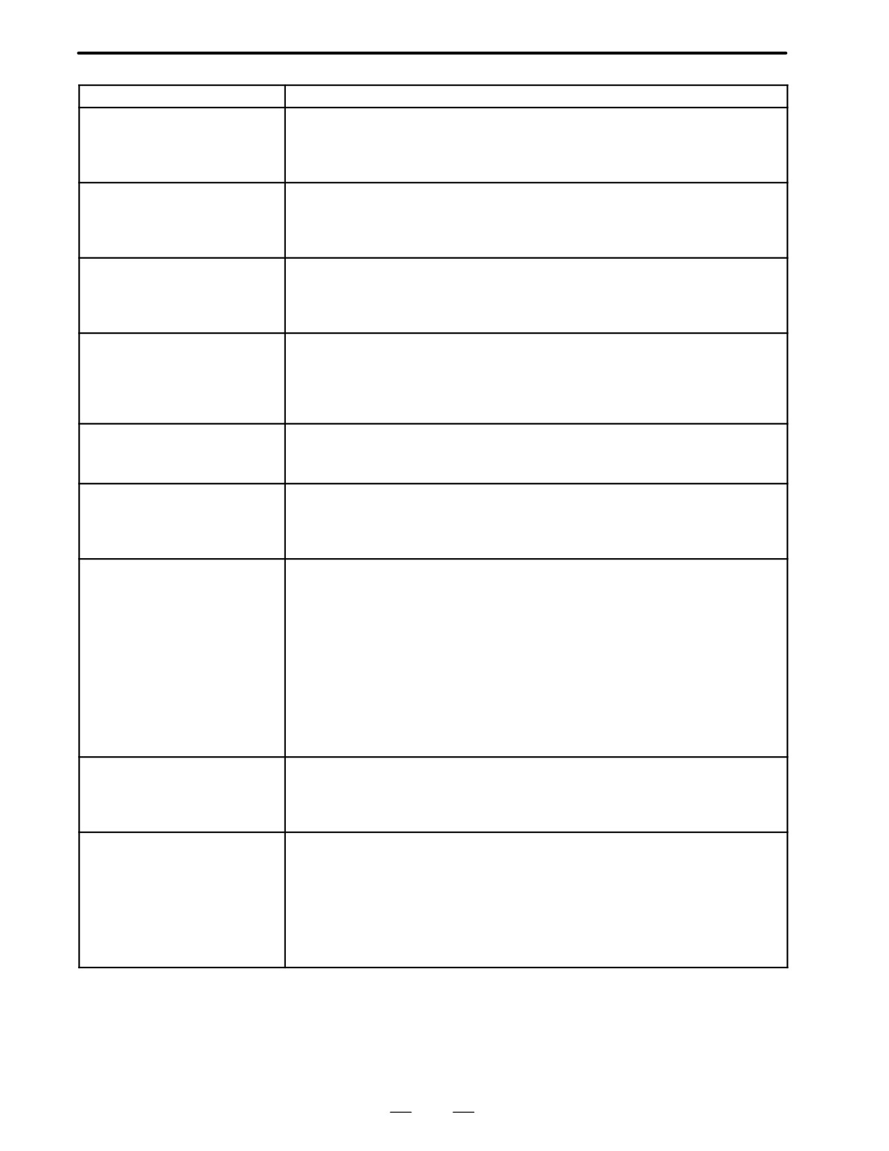
Message
Contents and solution
WN27 CODE SEG TYPE ER-
The code segment type is illegal. The code segment of RENAMESEG in the binding
ROR
control file is wrong.
(solution)
Please correct the entry of the code segment in the link control
statement to correspond to the entry in the build file.
WN28 DATA SEG TYPE ERROR
The data segment type is illegal. The data segment of RENAMESEG in the binding
control file is wrong.
(solution)
Please correct the entry of the code segment in the link control
statement to correspond to the entry in the build file.
WN29 COMMON MEM SEG
The segment type of common memory is illegal. The segment of RENAMESEG in
TYPE ERROR
the building control file of the common memory is wrong.
(solution)
Please correct the entry of common memory in the link control
statement to correspond to the entry in the build file.
WN30 IMPOSSIBLE ALLOCATE
The memories for the data and stack etc. cannot be allocated.
MEM.
(solution)
Please confirm whether the value of code segment in build file and
USER GDT ADDRESS in link control statement is correct or not.
Or please reduce the value of MAX LADDER AREA SIZE of the system
parameter and the size of the stack in link control statement at the least
WN31 IMPOSSIBLE EXECUTE
The library function cannot be executed.
LIBRARY
(solution)
Please confirm the object model of the library.
Or, system ROM of PMC must be replaced with one of later version.
WN32 LNK CONTROL DATA
Link control statement data is illegal.
ERROR
(solution)
Please confirm whether the address of symbol RC_ CTLB_INIT in map
file is set to LANGUAGE ORIGIN of the system parameter. Or, please
make the link control statement again.
PC1nn CPU INTERPT xxxx yyy-
A CPU error (abnormal interrupt) occurred.
yyy
nn
: CPU exception handling code
It is an exception code of i80386. For details, please refer to the
manual of the CPU.
00 Division error such as a divisor is 0 in division instruction.
12 Stack exception such as violations of limit of stack segment.
13 General protection exception such as segment limit over.
xxxx
: Segment selector where system error occurred.
The selector of 0103-02FB is used by C language.
yyyyyy
: Offset address where system error occurred.
STATUS LED lL
Solution )
When C language is not used or when the cause is not found even if it
is checked C language, consult it.
PC130 RAM PARITY aa xxxx yy-
The parity error occurred on the debugging RAM of PMC.
yyyy
aa
: RAM PARITY ERROR information.
xxxx
: Segment selector where system error occurred.
STATUS LED VL
yyyyyy
: Offset address where system error occurred
PC140 NMI BOC bb xxxx yyyyyy
The RAM parity error or NMI(Non Maskable Interrupt) generated in module of PMC
engine.
bb
: RAM PARITY ERROR information.
1, 2, 4, 8
Parity error occurred on basic DRAM.
14,18
Parity error occurred on option DRAM.
20,60,A0,E0
Parity error occurred on SRAM.
xxxx
: Segment selector where system error occurred.
STATUS LED VL
yyyyyy
: Offset address where system error occurred.
459
B. ALARM LIST
APPENDIX
B-62445E/03
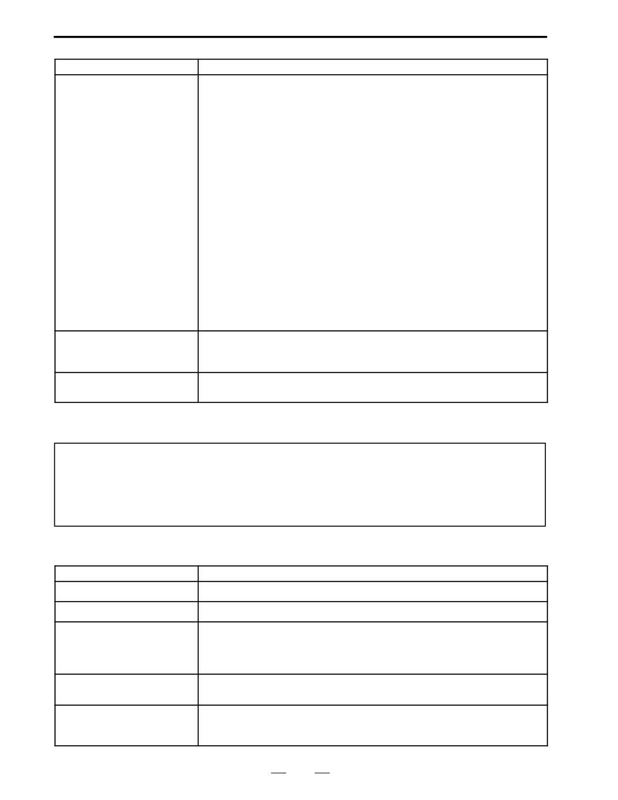
Message
Contents and solution
PC150 NMI SLC aa cc
The communication error occurred in the I/O Link.
aa, cc
: I/O Link error information. Note 2)
This error may occur by the following causes.
1. When I/O Unit-MODEL A is used, base1, 2 or 3 is not connected though
allocated.
2. The connection of cable is insufficient.
3. Defects of cable.
4. Defects of DI/DO units (I/O unit, Power Mate etc.)
5. Defects of PMC board (printed circuit board on host side where I/O Link cable is
connected.)
(solution)
Investigate the cause of error.
1. Please confirm the allocation data (by ”EDIT”→”MODULE” screen) and compare
with the actual connection.
2. Please confirm whether the cable is correctly connected.If you cannot find the
cause with the ways above, it may be the defect of hardware.
Please investigate a defective place by the following methods.
3. Please confirm the specification of the cable referring to”FANUC I/O Unit-MOD
EL A CONNECTION MAINTENANCE MANUAL (B-61813E)” or ”FANUC I/O
STATUS LED HL
Unit-MODEL B CONNECTION MANUAL (B-62163E)”.
4. Exchange the interface module of I/O Unit, the cable and the PMC board, etc.
one by one and, confirm whether this error occurs again.The communication may
fail by the noise etc. when this error still occurs after replacing all DI/DO units.
Please investigate the cause of noise.
PC160 F-BUS ERROR xxxx yyy-
The BUS error (access to disabled address) occurred.
yyy
xxxx
: Segment selector where system error occurred.
STATUS LED LV
yyyyyy
: Offset address where system error occurred
PC199 ROM PARITY eeeeeeee
The parity error occur in PMC system ROM.
STATUS LED Ll
eeeeeeee
: ROM parity error information.
STATUS LED (green) are LED1, LED2 on PMC-RC. CAP-II is LED3 and LED4.
V : OffH : OnlL : Blinking
Notes
1
The system error on PMC-RA1, RA2, RA3, RB,RB2 and RB3 is displayed as a system error
on the CNC side. (Refer to the “FANUC Series 16/18-MA Operator’s Manual(B-61874E)” or
“FANUC Series 16/18-TA Operator’s Manual(B-61804E)”.)
2
Error information is needed to investigate on FANUC, please take notes of it.
(2) Alarm messages (For EDIT 1)
Message
Contents and solution
ADDRESS BIT NOTHING
The address of the relay/coil is not set.
FUNCTION NOT FOUND
There is no functional instruction of the input number.
COM FUNCTION MISSING
The funcitonal instruction COM (SUB29) is not correctly dealt with.
Correspondence of COM and COME (SUB29) is incorrect.
Or, the number of coil controlled by COM is specified by the model which the number
cannot be specified.
EDIT BUFFER OVER
There in no empty area of the buffer for the editing.
(solution) Please reduce NET under editing.
END FUNCTION MISSING
Functional instruction END1,END2,END3 and END do not exist. Or, there are error
net in END1,END2,END3,END.
Or, order of END1,END2,END3, and END is not correct.
460
B-62445E/03
APPENDIX
B. ALARM LIST
Message
Contents and solution
ERROR NET FOUND
There is an error net.
ILLEGAL FUNCTION NO.
The wrong number of the functional instruction is searched.
FUNCTION LINE ILLEGAL
The functional instruction is not correctly connected.
HORIZONTAL LINE ILLEGAL
The horizontal line of the net is not connected.
ILLEGAL NET CLEARED
Because the power had been turn off while editing LADDER, some net under editing
was cleared.
ILLEGAL OPERATION
Operation is not correct.
The value is not specified and only INPUT key was pushed.
The address data is not correctly inputted.
Because the space to display the instruction on screen is not enough, the functional
instruction cannot be made.
SYMBOL UNDEFINED
The symbol which was inputted is not defined.
INPUT INVALID
There is an incorrect input data.
Non-numerical value was inputted with COPY, INSLIN,C-UP,C-DOWN etc.
The input address was specified for write coil.
An illegal character was specified for the data table.
NET TOO LARGE
The input net is larger than the editing buffer.
(solution) Please reduce the net under editing.
JUMP FUNCTION MISSING
The functional instruction JMP(SUB10) is not correctly dealt with.
Correspondence of JMP and JMPE(SUB30) is incorrect.
The number of coil to jump is specified by the model which the number of coil cannot
specified. (It is possible to specify the coil number only on PMC-RB/RC.)
LADDER BROKEN
LADDER is broken.
LADDER ILLEGAL
There is an incorrect LADDER.
IMPOSSIBLE WRITE
You try to edit sequence program on the ROM.
OBJECT BUFFER OVER
The sequence program area was filled.
(solution) Please reduce the LADDER.
PARAMETER NOTHING
There is no parameter of the functional instruction.
PLEASE COMPLETE NET
The error net was found in LADDER.
(solution) After correcting the error net, please continue operating.
PLEASE KEY IN SUB NO.
Please input the number of the functional instruction.
(solution) If you do not input the functional instruction, please push soft key ”FUNC”
again.
PROGRAM MODULE NOTHING
You tried to edit though there was neither RAM for debugging nor ROM for sequence
program.
RELAY COIL FORBIT
There is an unnecessary relay or coil.
RELAY OR COIL NOTHING
The relay or the coil does not suffice.
PLEASE CLEAR ALL
It is impossible to recover the sequence program.
(solution) Please clear the all data.
SYMBOL DATA DUPLICATE
The same symbol name is defined in other place.
COMMENT DATA OVERFLOW
The comment data area was filled.
(solution) Please reduce the number of the commnet.
461
B. ALARM LIST
APPENDIX
B-62445E/03
Message
Contents and solution
SYMBOL DATA OVERFLOW
The symbol data area was filled.
(solution) Please reduce the number of the symbol.
VERTICAL LINE ILLEGAL
There is an incorrect vertical line of the net.
MESSAGE DATA OVERFLOW
The message data area was filled.
(solution) Please reduce the number of the message.
1ST LEVEL EXECUTE TIME
The 1st level of LADDER is too large to complete execution in time.
OVER
(solution) Please reduce the 1st level of LADDER.
(3) Alarm messages (For I/O)
Message
Contents and solution
I/O OPEN ERROR nn
An error occurs when the reader/puncher interface was started.
nn=
-1 Because the interface is used with NC etc., the interface is not able to be
opened by PMC side.
(solution) After other functions finishes using the line, please execute again.
6
There is no option for the interface.
20 The interface cannot be opened.
(solution) Please confirm the connection of the cable. Please confirm
setting of the baud rate etc.
I/O WRITE ERROR nn
An output error occurred in the reader/puncher interface.
nn=
20 The state of the interface is not correct.
(solution) Please confirm the connection of the cable. Please confirm
setting the baud rate etc.
22 Opponent side is not ready to receive.
(solution) Please confirm the power supply on the opponent side.
Or, please initialize the interface.
I/O READ ERROR nn
An input error occurred in the reader/puncher interface.
nn=
20 The state of the interface is not correct.
(solution) Please confirm the connection of the cable. Please confirm
setting the baud rate etc.
21 The data is not sent from the opponent side.
(solution) Please confirm the power supply on the opponent side.
Please initialize the opponent side.
I/O LIST ERROR nn
An error occurred in directory read processing from FD Cassette.
nn=
20 The state of the interface is not correct.
(solution) Please confirm the connection of the cable. Please confirm
setting of the baud rate etc.
COMPARE ERR xxxxxx=aa:bb
A compare error occurred.
CONT? (Y/N)
xxxxxx
:
The Address where the compare error occurred.
aa
:
The data on PMC side.
bb
:
The data on device side
Enter’Y’ to continue processing.
ADDRESS IS OUT OF RANGE
The data transferred to the address out of the PMC debugging RAM area.
(xxxxxx)
xxxxxx : Transferred address.
(solution) Please confirm the address of the transferring data.
LADDER
:
Please confirm the model setting.
C language
:
Please confirm setting the address in the link control statement
and build file.
ROM WRITER ERROR nnnnnn
An error occurred in the ROM writer.
462
B-62445E/03
APPENDIX
B. ALARM LIST
B.3
SPINDLE ALARMS
Note
(SERIAL SPINDLE)
Er-xx is not displayed on CRT.
Message
Contents
Countermeasure
Er-01
*Although ESP (there are 2 types : connection signal
*Confirm the sequence of ESP and MRDY.
and PMC→CNC) and MRDY (machine ready signal)
are not input, SFR/SRV is input. However, regarding
MRDY, pay attention to the setting of use/not use
spindle parameter MRDY.
Er-02
If spindle motor is not integrated with spindle in system
Set the spindle motor speed detector parameter
with high-resolution magnetic pulse coder, speed de-
to 128 p/rev.
tector of spindle motor is set to 128 p/rev.
Attempt to excite motor fails if value other than 128
p/rev is set.
Er-03
Parameter for high-resolution magnetic pulse coder is
Check parameter setting for high-resolution
not set, but Cs contouring control command is entered.
magnetic pulse coder.
In this case, motor is not excited.
Er-04
Although parameter setting for using position coder
Confirm the parameter setting of the position
was not performed, commands for servo mode and
coder.
synchronous control are input.
In this case, the motor will not be excited.
Er-05
Although option parameter for orientation is not set, the
Confirm the parameter setting of orientation.
orientation command (ORCM) is input.
Er-06
Although option parameter for output switchover is not
Confirm the parameter setting for output switch-
set, LOW winding is selected.
ing and power line status signal.
Er-07
Although Cs contouring control command was entered,
Confirm the sequence.
SFR/SRV is not entered.
Er-08
Although servo mode control command was input,
Confirm the sequence.
SFR/SRV is not input.
Er-09
Although synchronous control command was input,
Confirm the sequence.
SFR/SRV is not input.
Er-10
Cs control command was entered, but another mode
Never set another mode when Cs contouring
(servo mode, synchronous control, orientation) is spe-
control command is being processed. Before
cified.
changing to another mode, clear Cs contouring
contorl command.
Er-11
Servo mode command was entered, but another mode
Do not command other modes during servo
(Cs contouring control, synchronous control, orienta-
mode command. When moving to other modes,
tion)is specified.
perform after releasing the servo mode com-
mand.
Er-12
Synchronous control command was entered, but
Do not command other modes during synchro-
another mode (Cs contouringt control, servo mode,
nous control command.
orientation) is specified.
When moving to other modes, perform after re-
leasing the synchronous control command.
Er-13
Orientation command was entered, but another mode
Do not command other modes during orientation
(Cs contouring control, servo mode, synchronous con-
command.
trol) is specified.
When moving to other modes, perform after re-
leasing the orientation command.
Er-14
SFR/SRV are simultaneously commanded.
Command one or the other.
Er-15
Cs contouring control command is entered when differ-
Check parameter setting and control input signal.
ential speed control function is enabled by parameter
setting (No.6500#5=1).
463
B. ALARM LIST
APPENDIX
B-62445E/03
Message
Contents
Countermeasure
Er-16
Differential mode command (DEFMDA) is entered
Check parameter setting and control input signal.
when differential speed function is disabled by parame-
ter setting (No.6500#5=1).
Er-17
Parameter setting (No.6511#0,1,2) for speed detector
Check parameter setting.
is incorrect.
(Specified speed detector is not present.)
Er-18
Spindle orientation command of position coder type is
Check parameter setting and control input signal.
entered when use of position coder signal is disabled
by parameter setting( No.6501#2=0).
Er-19
Although the command for orienting the magnetic sen-
Do not issue another mode while the orientation
sor system was entered, another mode was issued.
command is executed. Before issuing another
mode, cancel the orientation command.
Er-20
Both the slave mode and the high-resolution magnetic
These two settings are incompatible. Check the
pulse coder were enabled.
parameter settings.
Er-21
The slave mode command (SLV=1) was entered under
Enter the slave mode command in the normal
position control (servo mode, orientation,etc.).
operation mode.
Er-22
The position control command (servo mode, orienta-
Enter the position control command in the normal
tion,etc.) was entered in the slave operation mode
operation mode.
(SLV=1).
Er-23
A slave mode command was entered when the slave
Enable the slave mode.
mode is disabled.
Er-24
To perform continuous indexing in the mode for orient-
Check the control input signal (INCMD). To
ing the position coder system, incremental opera-
execute the absolute position command continu-
tion(INCMD=1) was first performed, then the absolute
ously, be sure to perform orientation with the ab-
position command (INCMD=0) was entered.
solute position command first.
Contact sig-
Between ESP1 and ESP2 of spindle control printed
Contact is open : emergency stop
nal of *ESP
circuit board
Contact is closed : general operation
Alarms (Serial spindle)
Alarm
Meaning
Description
Remedy
No.
”A”
Program ROM abnormality
Detects that control program is not started (due to
Install normal program
display
(not installed)
program ROM not installed, etc.)
ROM
AL-01
Motor
Detects motor speed exceeding specified speed
Check load status.
overheat
excessively.
Cool motor then reset
alarm.
AL-02
Excessive speed deviation
Detects motor speed exceeding specified speed
Check load status.
excessively.
Reset alarm.
AL-03
DC link section fuse blown
Detects that fuse F4 in DC link section is blown
Check power transistors,
(models 30S and 40S).
and so forth.
Replace fuse.
AL-04
Input fuse blown.
Detects blown fuse (F1 to F3), open phase or mo-
Replace fuse.
Input power open phase.
mentary failure of power (models 30S and 40S).
Check open phase and
power supply regenerative
circuit operation.
AL-05
Control power supply fuse
Detects that control power supply fuse AF2 or AF3
Check for control power
blown
is blown (models 30S and 40S).
supply short circuit .
Replace fuse.
AL-07
Excessive speed
Detects that motor rotation has exceeded 115% of
Reset alarm.
its rated speed.
464
B-62445E/03
APPENDIX
B. ALARM LIST
Alarm
Meaning
Description
Remedy
No.
AL-08
High input voltage
Detects that switch is flipped to 200 VAC when
Flip switch to 230 VAC.
input voltage is 230 VAC or higher (models 30S
and 40S).
AL-09
Excessive load on main cir-
Detects abnormal temperature rise of power tran-
Cool radiator then reset
cuit section
sistor radiator.
alarm.
AL-10
Low input voltage
Detects drop in input power supply voltage.
Remove cause, then reset
alarm.
Alarm
Meaning
Description
Remedy
No.
AL-11
Overvoltage in DC link sec-
Detects abnormally high direct current power sup-
Remove cause, then reset
tion
ply voltage in power circuit section.
alarm.
AL-12
Overcurrent in DC link section
Detects flow of abnormally large current in direct
Remove cause, then reset
current section of power cirtcuit
alarm.
AL-13
CPU internal data memory
Detects abnormality in CPU internal data memory.
Remove cause, then reset
abnormality
This check is made only when power is turned on.
alarm.
AL-15
Spindle switch/output switch
Detects incorrect switch sequence in spindle
Check sequence.
alarm
switch/output switch operation.
AL-16
RAM abnormality
Detects abnormality in RAM for external data. This
Remove cause, then reset
check is made only when power is turned on.
alarm.
AL-18
Program ROM sum check er-
Detects program ROM data error.This check is
Remove cause, then reset
ror
made only when power is turned on.
alarm.
AL-19
Excessive U phase current
Detects excessive U phase current detection ciu-
Remove cause, then reset
detection circuit offset
cuit offset.
alarm.
This check is made only when power is turned on.
AL-20
Excessive V phase current
Detects excessive V phase current detection cir-
Remove cause, then reset
detection circuit offset
cuit offset.
alarm.
This check is made only when power is turned on.
AL-24
Serial transfer data error
Detects serial transfer data error (such as NC pow-
Remove cause, then reset
er supply turned off, etc.)
alarm.
AL-25
Serial data transfer stopped
Detects that serial data transfer has stopped.
Remove cause, then reset
alarm.
AL-26
Disconnection of speed
Detects abnormality in position coder signal(such
Remove cause, then reset
detection signal for Cs con-
as unconnected cable and parameter setting er-
alarm.
touring control
ror).
AL-27
Position coder signal discon-
Detects abnormality in position coder signal (such
Remove cause, then reset
nection
as unconnected cable and adjustment error).
alarm.
AL-28
Disconnection of position
Detects abnormality in position detection signal for
Remove cause, then reset
detection signal for Cs con-
Cs contouring control (such as unconnected cable
alarm.
touring control
and adjustment error).
AL-29
Short-time overload
Detects that overload has been continuously ap-
Remove cause, then reset
plied for some period of time (such as restraining
alarm.
motor shaft in positioning).
AL-30
Input circuit overcurrent
Detects overcurrent flowing in input circuit.
Remove cause, then reset
alarm.
465
B. ALARM LIST
APPENDIX
B-62445E/03
Alarm
Meaning
Description
Remedy
No.
AL-31
Speed detection signal dis-
Detects that motor cannot rotate at specified
Remove cause, then reset
connection motor restraint
speed or it is detected that the motor is clamped.
alarm.
alarm or motor is clamped.
(but rotates at very slow speed or has stopped).
(This includes checking of speed detection signal
cable.)
AL-32
Abnormality in RAM inside
Detects abnormality in RAM inside the LSI used
Remove cause, then reset
the LSI used for serial data
for serial data transfer. This check is made only
alarm.
transfer. This check is made
when power is turned on.
only when power is turned on.
AL-33
Insufficient DC link section
Detects insufficient charging of direct current pow-
Remove cause, then reset
charging
er supply voltage in power circuit section when
alarm.
magnetic contactor in amplifier is turned on (such
as open phase and defectifve charging resistor).
AL-34
Parameter data setting be-
Detects parameter data set beyond allowable
Set correct data.
yond allowable range of val-
range of values.
ues
AL-35
Excessive gear ratio data set-
Detects gear ratio data set beyond allowable
Set correct data.
ting
range of values.
Alarm
Meaning
Description
Remedy
No.
AL-36
Error counter overflow
Detects error counter overflow.
Correct cause, then reset
alarm.
AL-37
Speed detector parameter
Detects incorrect setting of parameter for number
Set correct data.
setting error
of speed detection pulses.
AL-39
Alarm for indicating failure in
Detects 1-rotaion signal detection failure in Cs
Make 1-rotaion signal ad-
detecting 1-rotation signal for
contouring contorl.
justment.
Cs contouring control
Check cable shield status.
AL-40
Alarm for indicating 1-rotation
Detects that 1-rotation signal has not occurred in
Make 1-rotaion signal ad-
signal for Cs contouring con-
Cs contouring control.
justment.
trol not detected
AL-41
Alarm for indicating failure in
Detects failure in detecting position coder 1-rota-
Make signal adjustment
detecting position coder 1-ro-
tion signal.
for signal conversion cir-
taion signal.
cuit.
Check cable shield status.
AL-42
Alarm for indicating position
Detects that position coder 1-rotation signal has
Make 1-rotation signal ad-
coder 1-rotation signal not
not issued.
justment for signal conver-
detected
sion circuit.
AL-43
Alarm for indicating discon-
Detects that main spindle position coder signal
Check that main spindle
nection of position coder sig-
used for differential speed mode is not connected
position coder signal is
nal for differential speed
yet (or is disconnected).
connected to connector
mode
CN12.
AL-46
Alarm for indicating failure in
Detects failure in detecting position coder 1-rota-
Make 1-rotation signal ad-
detecting position coder
tion signasl in thread cutting operation.
justment for signal conver-
1-rotation signal in thread
sion circuit.
cutting operation.
Check cable shield status.
466
B-62445E/03
APPENDIX
B. ALARM LIST
Alarm
Meaning
Description
Remedy
No.
AL-47
Position coder signal ab-
Detects incorrect position coder signal count op-
Make signal adjustment
normality
eration.
for signal conversion cir-
cuit.
Check cable shield status.
AL-49
The converted differential
Detects that speed of other spindle converted to
Calculate differential
speed is too high.
speed of local spindle has exceeded allowable
speed by multiplying
limit in differential mode.
speed of other spindle by
gear ratio. Check if calcu-
lated value is not greater
than maximum speed of
motor.
AL-50
Excessive speed command
Detects that speed command calculation value
Calculate motor speed by
calculation value in spindle
exceeded allowable range in spindle synchroniza-
multiplying specified
synchronization control
tion control.
spindle speed by gear ra-
tio. Check if calculated
value is not greater than
maximum speed of motor.
AL-51
Undervoltage at DC link sec-
Detects that DC power supply voltage of power
Remove cause, then reset
tion
circuit has dropped (due to momentary power fail-
alarm.
ure or loose contact of magnetic contactor).
AL-52
ITP signal abnormality I
Detects abnormality in synchronization signal (ITP
Replace servo amp. PCB.
signal ) used in software.
AL-53
ITP signal abnormality II
Detects abnormality in synchronization signal (ITP
Replace servo amp. PCB.
signal) used in hardware.
AL-54
Overload current alarm
Detects that excessive current flowed in motor for
Remove overload of motor
long time.
and reset the alarm.
AL-55
Power line abnormality in
Detects that switch request signal does not match
Check if power line status,
spindle switching/output
power line status check signal.
check signal is processed
switching
normally.
467
B. ALARM LIST
APPENDIX
B-62445E/03
B.4
SPINDLE ALARMS
(ANALOG
INTERFACE)
(S SERIES AC
SPINDLE)
Spindle alarms of Model 1S to 3S
Alarm
Meaning
Description
Remedy
No.
”A”
Program ROM abnormality
Detects abnormality in ROM.
Exchange ROM
display
(not installed)
AL-01
Motor
Detects motor speed exceeding specified speed
Check load status.
overheat
excessively.
Cool motor then reset
alarm.
AL-02
Excessive speed deviation
Detects motor speed exceeding specified speed
Check load status.
excessively.
Reset alarm.
AL-03
Defective regenerative
Detects that regenerative current has flown longer
Reset alarm after check-
current
than the allowable time.
ing cutting condition etc.
AL-04
Not used
AL-05
Not used
AL-06
Excessive speed (Analog)
Detects that motot rotation has exceeded 115% of
Reset alarm.
its rated speed.
AL-07
Excessive speed (Digital)
Detects that motor rotation has exceeded 115% of
Reset alarm.
its rated speed.
AL-08
High input voltage
Detects that input voltage is 230 VAC or higher .
Flip switch to 230 VAC.
AL-09
Not used
AL-10
Low input voltage
Detects drop in +15V power supply or input power
Remove cause, then reset
supply voltage.
alarm.
AL-11
Overvoltage in DC link sec-
Detects abnormally high direct current power sup-
Remove cause, then reset
tion
ply voltage in power circuit section.
alarm.
AL-12
Overcurrent in DC link section
Detects flow of abnormally large current in direct
Check transistor and mo-
current section of power cirtcuit
tor coils for their ground-
ing, remove cause, then
reset alarm.
AL-13
Defectives CPU and
Detects abnormal transmission between CPU and
Exchange PCB.
peripherals
peripherals
AL-14
ROM abnormality
Detects abnormality in ROM.
Exchange ROM or PCB.
AL-15
Not used
AL-16
NVRAM abnormality
Detects abnormality in NVRAM for external data.
Exchange NVRAM or
AL-17
PCB.
AL-18
Defectives CPU and
Detects abnormal transmission between CPU and
Exchange PCB.
∼
peripherals
peripherals
AL-23
468
B-62445E/03
APPENDIX
B. ALARM LIST
Spindle alarms of Model 6S to 26S
Alarm
Meaning
Description
Remedy
No.
”A”
Program ROM abnormality
Detects abnormality in ROM.
Exchange ROM
display
(not installed)
AL-01
Motor
Detects motor speed exceeding specified speed
Check load status.
overheat
excessively.
Cool motor then reset
alarm.
AL-02
Excessive speed deviation
Detects motor speed exceeding specified speed
Check load or other status
excessively.
on the motor, correct fail-
ure, then reset the alarm.
AL-03
+24V fuse is blown.
+24V fuse of the control power is blown
Check control power if it is
shorted and replace
fuses.
AL-04
Blown of input fuse
One of fuse F1 to F3 is flown or lack of phase or
Check lack of phase of
Lack of phase of input power
momentary power failure was detected.
power supply and power
supply
regenerative circuit and
replace fuse if required.
AL-05
Not used
AL-06
Excessive speed (Analog)
Detects that motot rotation has exceeded 115% of
Remove cause, then reset
its rated speed.
alarm.
AL-07
Excessive speed (Digital)
Detects that motor rotation has exceeded 115% of
Remove cause, then reset
its rated speed.
alarm.
AL-08
High input voltage
Detects that input voltage is 230 VAC or higher .
Flip switch to 230 VAC.
AL-09
Overheat of radiator
Temperature of radiator used for transistor is ex-
Cool radiator then reset
tremely high.
alarm.
AL-10
Low input voltage
Detects drop in +15V power supply or input power
Remove cause, then reset
supply voltage.
alarm.
AL-11
Overvoltage in DC link sec-
Detects abnormally high direct current power sup-
Remove cause, then reset
tion
ply voltage in power circuit section.
alarm.
AL-12
Overcurrent in DC link section
Detects flow of abnormally large current in direct
Remove cause, then reset
current section of power cirtcuit
alarm.
AL-13
Defectives CPU and
Detects abnormal transmission between CPU and
Exchange PCB.
peripherals
peripherals
AL-14
ROM abnormality
Detects abnormality in ROM.
Exchange ROM or PCB.
AL-15
Defective optional circuit
Detects defective optional circuit (switch sequence
Check sequence ,then
in spindle switch/output switch operation) and erro-
exchange PCB.
neous connection to optional circuit.
AL-16
NVRAM abnormality
Detects abnormality in NVRAM for external data.
Exchange NVRAM or
AL-17
PCB.
AL-18
Defectives CPU and
Detects abnormal transmission between CPU and
Exchange PCB.
∼
peripherals
peripherals
AL-23
* Not displayed in PCB version number 10B and later.
469

B. ALARM LIST
APPENDIX
B-62445E/03
D Method of resetting
DATA
Press
MODE
and
SET
key at the same time.
alarm
Note
There is a possibility that the spindle may rotate immediately after
an alarm is released. Therefore, reset an alarm under the
emergency stop state and the rotation command being off.
Alarm is not released if the cause of the alarm is not removed.
470

C. LIST OF MAINTENANCE
APPENDIX
B-62445E/03
PARTS
LIST OF MAINTENANCE PARTS
C
C.1MAINTENANCE PARTS .
472
471
C. LIST OF MAINTENANCE
PARTS
APPENDIX
B-62445E/03
C.1
MAINTENANCE
PARTS
Maintenance Parts
Consumables here refer to the parts which
are not
reused
after
replacement. Rank : AA>A>BB>B>CC>C
Compati-
Ra
Name
Drawing number
Remarks
bility
nk
Fan motor
For 2-slot case
A90L-0001-0378
One piece required per 2 slots
2.4W
A
For 1-slot case
A90L-0001-0385#A
Two pieces are required at the 3rd
1.7W
A
slot track
Battery
A98L-0031-0012
A
Fuse
For AI
A60L-0001-0245#GP75
F1(7.5A)
B
A60L-0001-0075#3.2
F3 (3.2A)
B
A60L-0001-0046#5.0
F4 (5AS)
B
For BI
A60L-0001-0245#GP75
F1 (7.5A)
B
A60L-0001-0075#5.0
F3 (5A)
B
A60L-0001-0046#5.0
F4 (5AS)
B
Small
TB
A86L-0001-0171#ST2
Usable units
B
keyboard
A02B-0120-C041#TA
A02B-0120-C042#TA
A02B-0120-C043#TA
A02B-0120-C121#TA
A86L-0001-0171#ST2R
Usable units
B
A02B-0120-C041#TAR
A02B-0120-C043#TAR
A02B-0120-C121#TAR
A86L-0001-0171#ST2S
Usable units
B
A02B-0120-C041#TAS
A02B-0120-C043#TAS
A02B-0120-C121#TAS
MB
A86L-0001-0171#SM2
Usable units
B
A02B-0120-C041#MA
A02B-0120-C042#MA
A02B-0120-C121#MA
A86L-0001-0171#SM2R
Usable units
B
A02B-0120-C041#MAR
A02B-0120-C121#MAR
A86L-0001-0171#SM2S
Usable units
B
A02B-0120-C041#MAS
A02B-0120-C121#MAS
472

C. LIST OF MAINTENANCE
APPENDIX
B-62445E/03
PARTS
Compati-
Ra
Name
Drawing number
Remarks
bility
nk
Standard
TB
A86L-0001-0172#HT2
Usable units
B
keyboard
A02B-0120-C051#TA
A02B-0120-C052#TA
A02B-0120-C122#TA
A86L-0001-0172#HT2R
Usable units
B
A02B-0120-C051#TAR
A02B-0120-C122#TAR
A86L-0001-0172#HT2S
Usable units
B
A02B-0120-C051#TAS
A02B-0120-C122#TAS
MB
A86L-0001-0172#HM2
Usable units
B
A02B-0120-C051#MA
A02B-0120-C052#MA
A02B-0120-C122#MA
A86L-0001-0172#HM2R
Usable units
B
A02B-0120-C051#MAR
A02B-0120-C122#MAR
A86L-0001-0172#HM2S
Usable units
B
A02B-0120-C051#MAS
A02B-0120-C122#MAS
Keyboard for
TB
A86L-0001-0173#HT2
Usable units
B
horizontal
A02B-0200-C061#TB
9.5″ LCD/
A02B-0200-C065#TB
MDI
A86L-0001-0173#HT2R
Usable units
B
A02B-0200-C061#TBR
A02B-0200-C065#TBR
A86L-0001-0173#HT2S
Usable units
B
A02B-0200-C061#TBS
A02B-0200-C065#TBS
With TB
A86L-0001-0173#HF1
Usable units
B
CAP-II
A02B-0200-C061#TFB
A02B-0200-C065#TFB
A86L-0001-0173#HF1R
Usable units
B
A02B-0200-C061#TFBR
A02B-0200-C065#TFBR
A86L-0001-0173#HF1S
Usable units
B
A02B-0120-C061#TFBS
A02B-0120-C065#TFBS
MB
A86L-0001-0173#HM2
Usable units
B
A02B-0200-C061#MB
A02B-0200-C065#MB
A86L-0001-0173#HM2R
Usable units
B
A02B-0200-C061#MBR
A02B-0200-C065#MBR
A86L-0001-0173#HM2S
Usable units
B
A02B-0200-C061#MBS
A02B-0200-C065#MBS
473
C. LIST OF MAINTENANCE
PARTS
APPENDIX
B-62445E/03
Compati-
Ra
Name
Drawing number
Remarks
bility
nk
Key board
TB
A86L-0001-0174#HT2
Usable units
B
for horizontal
A02B-0120-C071#TA
14″ CRT/
A02B-0120-C074#TA
MDI
A02B-0200-C071#TB
A02B-0200-C074#TB
A86L-0001-0174#HT2R
Usable units
B
A02B-0200-C071#TBR
A86L-0001-0174#HT2S
Usable units
B
A02B-0200-C071#TBS
With TB
A86L-0001-0174#HF1
Usable units
B
CAP-II
A02B-0120-C071#TF
A02B-0120-C071#TF
A02B-0200-C071#TFB
A02B-0200-C074#TFB
A86L-0001-0174#HF1R
Usable units
B
A02B-0200-C071#TFBR
A86L-0001-0174#HF1S
Usable units
B
A02B-0200-C071#TFBS
MB
A86L-0001-0174#HM2
Usable units
B
A02B-0120-C071#MA
A02B-0200-C071#MB
A86L-0001-0174#HM2R
Usable units
B
A02B-0200-C071#MBR
A86L-0001-0174#HM2S
Usable units
B
A02B-0200-C071#MBS
474
C. LIST OF MAINTENANCE
APPENDIX
B-62445E/03
PARTS
Compati-
Ra
Name
Drawing number
Remarks
bility
nk
Keyboard for
TB
A86L-0001-0175#VT2
Usable units
B
vertical 9.5″
A02B-0120-C072#TA
LCD/MDI
A02B-0200-C062#TB
and 14″
A02B-0200-C066#TB
CRT/MDI
A86L-0001-0175#VT2R
Usable units
B
A02B-0200-C062#TBR
A02B-0200-C066#TBR
A86L-0001-0175#VT2S
Usable units
B
A02B-0200-C062#TBS
A02B-0200-C066#TBS
With TB
A86L-0001-0175#VF1
Usable units
B
CAP-II
A02B-0120-C072#TF
A02B-0200-C062#TFB
A02B-0200-C066#TFB
A86L-0001-0175#VF1R
Usable units
B
A02B-0200-C062#TFBR
A02B-0200-C066#TFBR
A86L-0001-0175#VF1S
Usable units
B
A02B-0200-C062#TFBS
A02B-0200-C066#TFBS
MB
A86L-0001-0175#VM2
Usable units
B
A02B-0120-C072#MA
A02B-0200-C062#MB
A02B-0200-C066#MB
A86L-0001-0175#VM2R
Usable units
B
A02B-0200-C062#MBR
A02B-0200-C066#MBR
A86L-0001-0175#VM2S
Usable units
B
A02B-0200-C062#MBS
A02B-0200-C066#MBS
475
C. LIST OF MAINTENANCE
PARTS
APPENDIX
B-62445E/03
Maintenance Parts (Parts to be repaired by us)
Compati-
Ra
Name
Drawing number
Remarks
bility
nk
Series 16
2-SLOT
A02B-0200-C001
C
control rack
(without
A02B-0200-C021
For power C
C
MMC–IV)
3-SLOT
A02B-0200-C005
C
4-SLOT
A02B-0200-C002
C
6-SLOT
A02B-0200-C003
C
8-SLOT
A02B-0200-C004
C
Series 16
4-SLOT
A02B-0200-C010
C
control rack
(with MMC-
6-SLOT
A02B-0200-C011
C
IV)
8-SLOT
A02B-0200-C012
C
Series 18
2-SLOT
A02B-0129-C001
C
control rack
(without
A02B-0129-C021
For power C
C
MMC–IV)
3-SLOT
A02B-0129-C005
C
4-SLOT
A02B-0129-C002
C
6-SLOT
A02B-0129-C003
C
Series 18
4-SLOT
A02B-0129-C010
C
control rack
(with MMC-
6-SLOT
A02B-0129-C011
C
IV)
Power sup-
AI
A16B-1212-0900
B
ply unit
Power sup-
BI
A16B-1212-0870
B
ply unit
Power sup-
C
A20B-1005-0420
B
ply unit
Main CPU
Series 16
A16B-3200-0010
MAIN-A, 4 axes
B
board
A16B-3200-0170
B
A16B-3200-0110
MAIN-B, 6 axes
B
Series 18
A16B-2202-0860
4-axis specification
B
A16B-3200-0160
6-axis specification
B
476
C. LIST OF MAINTENANCE
APPENDIX
B-62445E/03
PARTS
Compati-
Ra
Name
Drawing number
Remarks
bility
nk
Option 1
Graphic+
A16B-2200-0918
B
board
remote buffer
Graphic+ DNC1
A16B-2200-0916
B
Remote
A16B-2200-0913
B
buffer
DNC1
A16B-2200-0914
B
Graphic
A16B-2200-0919
B
Option 2
Series 16 with
A16B-2202-0400
MAIN-A specification,
B
board
sub-CPU
4 axes
A16B-2202-0890
B
Series 16 with-
A16B-2202-0401
MAIN-A specification,
B
out
4 axes
sub-CPU
A16B-2202-0891
B
Series 16 with
A16B-2202-0850
MAIN-B specification,
B
sub-CPU
6 axes
Series 16 with-
A16B-2202-0851
MAIN-B specification
B
out
sub-CPU
Series 18 with
A16B-2202-0853
B
sub-CPU
Option 3
PMC-RC
A16B-3200-0055
B
board
+CAP-II
PMC-RC
A16B-3200-0054
B
CAP-II
A16B-3200-0057
B
Loader con-
Series 16
A16B-2202-0560
MAIN-A specification
B
trol board
Series 18
A16B-2202-0880
MAIN-B specification
B
Background drawing board
A16B-2202-0852
B
477
C. LIST OF MAINTENANCE
PARTS
APPENDIX
B-62445E/03
Compati-
Ra
Name
Drawing number
Remarks
bility
nk
I/O card
A(40/40)
A16B-2200-0958
Without high-speed skip signal input
B
(sink type
output)
B(80/56)
A16B-2200-0957
B
C(104/72)
A16B-2200-0956
B
D(156/120)
A16B-2200-0955
Without high-speed skip signal input
B
A20B-9001-0480
To be used as a pair.
E(40/40)
A16B-2200-0953
With high-speed skip signal input
B
F(80/56)
A16B-2200-0952
B
G(104/72)
A16B-2200-0951
B
H(156/120)
A16B-2200-0950
With high-speed skip signal input
B
A20B-9001-0480
To be used as a pair.
I
A16B-2200-0954
High-speed skip signal input only
B
I/O card
A(40/40)
A16B-2200-0988
Without high-speed skip signal input
B
(source type
output)
A16B-2202-0728
B
B(80/56)
A16B-2200-0987
B
A16B-2202-0727
B
C(104/72)
A16B-2200-0986
B
A16B-2202-0726
B
D(156/120)
A16B-2202-0725
Without high-speed skip signal input
B
A20B-8001-0150
To be used as a pair.
E(40/40)
A16B-2200-0983
With high-speed skip signal input
B
A16B-2202-0723
B
F(80/56)
A16B-2200-0982
B
A16B-2202-0722
B
G(104/72)
A16B-2200-0981
B
A16B-2202-0721
B
H(156/120)
A16B-2202-0720
With high-speed skip signal input
B
A20B-8001-0150
To be used as a pair.
Operator’s
A(64/32)
A16B-2200-0661
B
panel con-
nection unit
(sink type
B(94/64)
A16B-2200-0660
B
output)
Operator’s
A(64/32)
A16B-2202-0731
B
panel con-
nection unit
(source type
B(94/64)
A16B-2202-0730
B
output)
Operator’s panel interface unit
A16B-2201-0110
B
478
C. LIST OF MAINTENANCE
APPENDIX
B-62445E/03
PARTS
Compati-
Ra
Name
Drawing number
Remarks
bility
nk
Serial/DMA
4CH
A20B-2200-0010
For option 3 board
B
add–on
board
2CH
A20B-2200-0011
B
Graphic
For 2 paths
A20B-8200-0010
For main CPU board
B
add–on
board
For 1 path
A20B-8200-0011
B
PMC control
For PMC-RE
A20B-2900-0140
B
module
Loader control,
A20B-2900-0142
B
with SLC
Loader control,
A20B-2900-0143
B
without SLC For
PMC-RC3
For PMC-
A20B-2901-0960
B
RB3/RC3, with
SLC
For PMC-
A20B-2901-0961
B
RB3/RC3, with-
out SLC
High-speed
Analog I/O +
A20B-2900-0280
B
DI, analog
high-speed skip
I/O module
DI
High-speed skip
A20B-2900-0281
B
DI
ROM module
1MB
A20B-2900-0290
B
768KB
A20B-2900-0291
B
Graphic control module
A20B-2900-0311
B
Grahic CPU module
A20B-2900-0350
B
SRAM module (512 KB)
A20B-2900-0541
B
14-bit A/D converter module
A20B-2900-0580
B
SRAM module (2 MB)
A20B-2900-0991
B
CAP-II CPU module
A20B-2901-0390
B
DRAM/SRAM module
A20B-2901-0413
B
DRAM mod-
6MB
A20B-2901-0940
B
ule
4MB
A20B-2901-0941
B
2MB
A20B-2901-0942
B
479
C. LIST OF MAINTENANCE
PARTS
APPENDIX
B-62445E/03
Compati-
Ra
Name
Drawing number
Remarks
bility
nk
Spindle con-
Serial +
A20B-2901-0980
For main CPU board
B
trol module
analog
Serial
A20B-2901-0981
B
Analog
A20B-2901-0982
B
Serial +
A20B-2901-0984
For option 2 board
B
analog
Serial
A20B-2901-0985
B
Analog
A20B-2901-0986
B
Servo control module
A20B-2901-0060
B
A20B-2901-0061
For learning-control function
B
FROM/
FROM 4MB
A20B-2902-0080
B
SRAM mod-
SRAM 512KB
ule
FROM 4MB
A20B-2902-0081
B
FROM 2MB
A20B-2902-0082
B
FROM/
FROM 8MB
A20B-2902-0090
B
SRAM mod-
SRAM 2MB
ule
FROM 8MB
A20B-2902-0091
B
FROM 6MB
A20B-2902-0092
B
FROM 8MB
A20B-2902-0093
B
SRAM 512KB
FROM 6MB
A20B-2902-0094
B
SRAM 512KB
DRAM mod-
512KB+2MB
A20B-2902-0191
B
ule
512KB+1MB
A20B-2902-0192
B
512KB+
A20B-2902-0193
B
512KB
512KB
A20B-2902-0194
B
2MB
A20B-2902-0196
B
1MB
A20B-2902-0197
B
512KB
A20B-2902-0198
B
PMC control module
A20B-2902-0250
B
For PMC-RC4/RB4
480
C. LIST OF MAINTENANCE
APPENDIX
B-62445E/03
PARTS
Compati-
Ra
Name
Drawing number
Remarks
bility
nk
CRT control
For 14″CRT
A20B-2902-0270
When MMC is not provided
B
module
For 9″CRT
A20B-2902-0271
B
For LCD
A20B-2902-0272
B
For 14″CRT
A20B-2902-0273
When MMC is provided
B
For LCD
A20B-2902-0275
B
For 9″CRT
A20B-2902-0276
When MMC is not provided
B
For LCD
A20B-2902-0277
B
For 14″CRT
A20B-2902-0278
B
FROM/
FROM 4MB
A20B-2902-0341
B
SRAM mod-
SRAM 256KB
ule
FROM 4MB
A20B-2902-0343
B
SRAM 256KB
SRAM mod-
256KB
A20B-2902-0350
B
ule
256KB+
A20B-2902-0351
B
512KB
256KB+2MB
A20B-2902-0352
B
FROM/
FROM 8MB
A20B-2902-0410
B
SRAM mod-
SRAM 256KB
ule
FROM 6MB
A20B-2902-0411
B
SRAM 256KB
Series 16
2-SLOT
A20B-2000-0630
B
control rack
(without
A20B-2001-0870
For I/O card with power supply
B
MMC–IV)
3-SLOT
A20B-2000-0620
B
4-SLOT
A20B-2000-0640
B
6-SLOT
A20B-2000-0650
B
8-SLOT
A20B-2000-0610
Series 16
4-SLOT
A20B-2001-0490
B
control rack
(with MMC-
6-SLOT
A20B-2001-0652
B
IV)
8-SLOT
A20B-2001-0662
B
Series 18
2-SLOT
A20B-2002-0090
B
control rack
(without
A20B-2002-0110
For I/O card with power supply
B
MMC–IV)
3-SLOT
A20B-2002-0020
B
4-SLOT
A20B-2001-0190
6-SLOT
A20B-2001-0200
B
481

C. LIST OF MAINTENANCE
PARTS
APPENDIX
B-62445E/03
Compati-
Ra
Name
Drawing number
Remarks
bility
nk
Series 18
4-SLOT
A20B-2002-0100
B
control rack
(with MMC-
6-SLOT
A20B-2002-0120
B
IV)
Optical I/O link adapter
A13B-0154-B001
B
482
C. LIST OF MAINTENANCE
APPENDIX
B-62445E/03
PARTS
Maintenance Parts
Compati-
Ra
Name
Drawing number
Remarks
bility
nk
9″ CRT/MDI
TB
A02B-0120-C041#TA
For system without MMC-IV
B
(Small key,
A02B-0120-C041#TAR
B
monochrome)
A02B-0120-C041#TAS
B
A02B-0120-C043#TA
B
A02B-0120-C043#TAR
B
A02B-0120-C043#TAS
B
MB
A02B-0120-C041#MA
B
A02B-0120-C041#MAR
B
A02B-0120-C041#MAS
B
9″ CRT/MDI
TB
A02B-0120-C042#TA
B
(Small key,
color)
MB
A02B-0120-C042#MA
B
9″ CRT/MDI
TB
A02B-0120-C051#TA
B
(Standard key,
A02B-0120-C051#TAR
B
monochrome)
A02B-0120-C051#TAS
B
MB
A02B-0120-C051#MA
B
A02B-0120-C051#MAR
B
A02B-0120-C051#MAS
B
9″ CRT/MDI
TB
A02B-0120-C052#TA
B
(Small key,
color)
MB
A02B-0120-C052#MA
B
9″ PDP/MDI
TB
A02B-0120-C081#TA
B
(Standard key,
A02B-0200-C101#TBR
B
monochrome)
A02B-0200-C101#TBS
B
MB
A02B-0120-C081#MA
B
A02B-0200-C101#MBR
B
A02B-0200-C101#MBS
B
9″ separate
mono-
A02B-0120-C111
B
type CRT unit
chrome
color
A02B-0120-C112
B
9″ separate
mono-
A02B-0120-C113
B
type PDP unit
chrome
color
A02B-0120-C100
B
8.4″ separate
color
A02B-0200-C050
B
type LCD unit
7.2″ separate
mono-
A02B-0200-C081
B
type LCD unit
chrome
483
C. LIST OF MAINTENANCE
PARTS
APPENDIX
B-62445E/03
Compati-
Ra
Name
Drawing number
Remarks
bility
nk
Separate type
TB
A02B-0120-C121#TA
It is not relative whether with MMC-IV or not
B
MDI unit
A02B-0120-C121#TAR
B
(small key)
A02B-0120-C121#TAS
B
MB
A02B-0120-C121#MA
B
A02B-0120-C121#MAR
B
A02B-0120-C121#MAS
B
Separate type
TB
A02B-0120-C122#TA
B
MDI unit
A02B-0120-C122#TAR
B
(standard key)
A02B-0120-C122#TAS
B
MB
A02B-0120-C122#MA
B
A02B-0120-C122#MAR
B
A02B-0120-C122#MAS
B
9.5″ LCD/MDI
TB
A02B-0200-C061#TB
For system without MMC-IV
B
unit horizontal
A02B-0200-C061#TBR
B
A02B-0200-C061#TBS
B
TB With
A02B-0200-C061#TFB
B
CAP–II
A02B-0200-C061#TFBR
B
A02B-0200-C061#TFBS
B
MB
A02B-0200-C061#MB
B
A02B-0200-C061#MBR
B
A02B-0200-C061#MBS
B
9.5″ LCD/MDI
TB
A02B-0200-C062#TB
B
unit vertical
A02B-0200-C062#TBR
B
A02B-0200-C062#TBS
B
TB With
A02B-0200-C062#TFB
B
CAP–II
A02B-0200-C062#TFBR
B
A02B-0200-C062#TFBS
B
MB
A02B-0200-C062#MB
B
A02B-0200-C062#MBR
B
A02B-0200-C062#MBS
B
14″ CRT/MDI
TB
A02B-0120-C071#TA
B
horizontal
TB With
A02B-0120-C071#TF
B
CAP-II
MB
A02B-0120-C071#MA
B
TB
A02B-0120-C074#TA
B
TB With
A02B-0120-C074#TF
B
CAP-II
14″ CRT/MDI
TB
A02B-0120-C072#TA
For system without MMC-IV
B
vertical
TB With
A02B-0120-C072#TF
B
CAP-II
MB
A02B-0120-C072#MA
B
484
C. LIST OF MAINTENANCE
APPENDIX
B-62445E/03
PARTS
Compati-
Ra
Name
Drawing number
Remarks
bility
nk
14″ CRT/MDI
TB
A02B-0200-C071#TB
For system with MMC-IV
B
horizontal
A02B-0200-C071#TBR
B
A02B-0200-C071#TBS
B
TB With
A02B-0200-C071#TFB
B
CAP–II
A02B-0200-C071#TFBR
B
A02B-0200-C071#TFBS
B
MB
A02B-0120-C071#MB
B
A02B-0200-C071#MBR
B
A02B-0200-C071#MBS
B
14″ CRT/MDI
TB
A02B-0200-C072#TB
For system with MMC-IV
B
vertical
A02B-0200-C072#TBR
B
A02B-0200-C072#TBS
B
TB With
A02B-0200-C072#TFB
B
CAP–II
A02B-0200-C072#TFBR
B
A02B-0200-C072#TFBS
B
MB
A02B-0120-C072#MB
B
A02B-0200-C072#MBR
B
A02B-0200-C072#MBS
B
9.5″ LCD/MDI
TB
A02B-0200-C065#TB
B
horizontal
A02B-0200-C065#TBR
B
A02B-0200-C065#TBS
B
TB With
A02B-0200-C065#TFB
B
CAP–II
A02B-0200-C065#TFBR
B
A02B-0200-C065#TFBS
B
MB
A02B-0120-C065#MB
B
A02B-0200-C065#MBR
B
A02B-0200-C065#MBS
B
9.5″ LCD/MDI
TB
A02B-0200-C066#TB
For system with MMC-IV
B
vertical
A02B-0200-C066#TBR
B
A02B-0200-C066#TBS
B
TB With
A02B-0200-C066#TFB
B
CAP–II
A02B-0200-C066#TFBR
B
A02B-0200-C066#TFBS
B
MB
A02B-0120-C066#MB
B
A02B-0200-C066#MBR
B
A02B-0200-C066#MBS
B
8.4″ separate
color
A02B-0200-C051
B
type LCD unit
9″ monochrome, CRT display
A61L-0001-0093
Usable unit
For
B
A02B-0120-C041#TA,#MA
system
A02B-0120-C051#TA,#MA
without
A02B-0120-C111
MMC-
IV
485
C. LIST OF MAINTENANCE
PARTS
APPENDIX
B-62445E/03
Compati-
Ra
Name
Drawing number
Remarks
bility
nk
9Imonochrome, CRT display
A61L-0001-0093#A
Usable unit
For
B
A02B-0120-C043#TA
system
without
9Icolor, CRT display
A61L-0001-0095
Usable unit
B
MMC-
A02B-0120-C041#TA,#MA
IV
A02B-0120-C052#TA,#MA
A02B-0120-C112
9Iplasma display
A61L-0001-0116
Usable unit
B
A02B-0120-C081#TA,#MA
A02B-0120-C113
14Icolor,CRT display
A61L-0001-0094#A
Usable unit
B
A02B-0120-C071#TA,#MA
#TF,#WA
A02B-0120-C072#TA,#MA
#TF,#MC
A02B-0120-C074#TA,#TF
9.5Icolor, LCD display
A61L-0001-0138
Usable unit
It is not
B
A02B-0200-C061#TB,#TFB
relative
#MB
wheth-
A02B-0200-C062#TB,#TFB
er with
#MB
MMC-
A02B-0200-C065#TB,#TFB
IV or
#MB
not
A02B-0200-C066#TB,#TFB
#MB
8.4Icolor, LCD display
A61L-0001-0139
Usable unit
B
A02B-0200-C050
A02B-0200-C051
486
B-62445E/03
APPENDIX
D. BOOT SYSTEM
BOOT SYSTEM
D
D.1OVERVIEW .
488
D.2SCREEN CONFIGURATION AND OPERATING
PROCEDURE .
490
D.3ERROR MESSAGES AND REQUIRED
ACTIONS .
504
487