FANUC Series 16 / 160 / 18 / 180 – Model B. Maintenance Manual - page 9
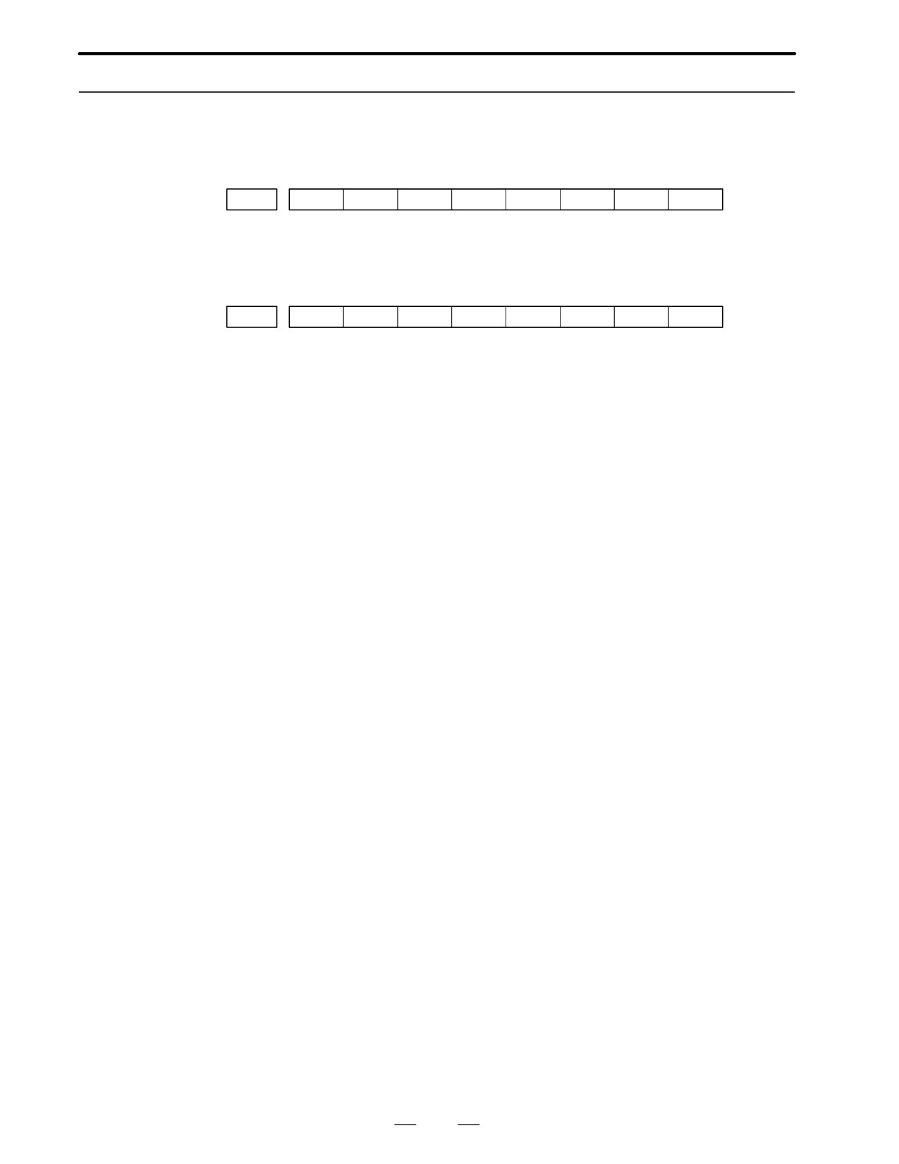
4. INTERFACE BETWEEN NC AND PMC
B-62445E/03
D Manual operation
MODE
INPUT/OUTPUT SIGNAL
FEED RATE,
ETC
Handle/
[PMC ⇒ CNC]
[PMC ⇒ CNC]
M
incremental
HSnA∼D (Axis selection) n:1∼3(No. of
MP1, MP2
A
MPGs)
(Multiplier)
N
U
JOG
+α, -α
(Jog feed)
[PMC ⇒ CNC]
A
[PMC ⇒ CNC]
*JV0∼15
L
RT
(Rapid traverse)
(Manual fee-
drate over-
O
ride)
[PMC ⇒ CNC]
P
ZRN(Reference position return mode)
+α, -α
(Man
E
ual feed move
R
[MT ⇒ CNC]
command)
*DECα
(Reference position deceleration)
A
Z
ROV1, ROV2
T
R
HROV
I
N
[CNC ⇒ PMC]
*HROV0∼6
O
ZPα
(Rapid tra-
N
ZP2α, ZP3α, ZP4α
verse over-
(Reference position return completion)
ride)
D Others
[PMC ⇒ CNC]
MD1∼4 (Mode selection)
*ESP
(Emergency stop)
KEY1∼4 (Memory protection key)
MLK,MLKα
(All axes/ each axis machine lock)
*IT,*ITα
(All axes/ each axis machine lock)
*"MITα (interlock per axis and direction:M series)
STLK
(Start lock:T series)
*ABSM (Manual absolute)
SVFα
(Servo off)
*FLWP
(Follow up)
ERS
(External reset)
RRW
(Reset & Rewind)
Others
EXLM
(Stored stroke limit external switching)
"LMα, RLSOT
(Software limit external setting M series)
*"Lα
(Overtravel limit)
*"EDα (External deceleration of each axis)
[CMC ⇒ PMC]
MA
(NC ready)
SA
(Servo ready)
AL
(NC alarm)
RST
(Resetting)
BAL
(Battery alarm)
INPα
(In-position)
MVα
(Axis moving)
TAP
(Tapping)
238
B-62445E/03
4.INTERFACE BETWEEN NC AND PMC
4.5
SIGNAL AND
SYMBOL
CORRESPONDENCE
TABLE
SYMBOL
PMC address
Signal names
A
*ABSM
G006.2
Manual Absolute Signal
AFL
G005.6
Auxiliary Function Lock Signal
*AFV0∼7
G013.0∼7
2nd Feedrate Override Signal
AL
F001.0
Alarm Signal
ALMA, B
F045.0,
Spindle Alarm Signal
F049.0
AR0∼15
F040.0∼7.
Actual Spindle Speed Signal
F041.0∼7
ARSTA, B
G071.0.
Spindle Alarm Reset Signal
G075.0
B
BAL
F001.2
Battery Alarm Signal
BDT1∼9
F044.0,
Optional Block Skip Signal
F045.0∼7
BF
F007.7
B Function Strobe Signal
BCLP
F061.1
B Axis Clamp Signal
BUCLP
F061.0
B Axis Unclamp Signal
*BECLP
G038.7
B Axis Clamp Completion Signal
*BEUCL
G038.6
B Axis Unlamp Completion Signal
B00∼B31
F030∼033
B Function Binary Code Signal
BFIN
G005.7
B Function Completion Signal
BGEACT
F053.4
Background Editing Signal
C
CDZ
G053.7
Chamfering Signal
CHPA, B
F046.0
Power Cable Switching Signal
F050.0
CFINA, B
F046.1
Switch Completion Signal
F050.1
CON
G027.7
Cs Axis Contouring Control Signal
CSS
F002.2
Constant Surface Speed Control Signal
CTHαA, B
G070.2, 3,
Clutch/Gear Selection Signal
G074.2, 3
239
4. INTERFACE BETWEEN NC AND PMC
B-62445E/03
SYMBOL
PMC address
Signal names
D
*DEC1∼8
X009.0∼7
Reference Position Return Deceleration Signal
DEN
F001.3
Distribution End Signal
DM00
F009.7
Decoded M00 Signal
DM01
F009.6
Decoded M01 Signal
DM02
F009.5
Decoded M02 Signal
DM30
F009.4
Decoded M30 Signal
DNCI
F043.5
Operation by I/O device Mode
DRN
G046.7
Dry Run Signal
DTCH1∼8
G124.0∼7
Controlled Axis Detach Signal
E
*ESP
X008.4, G008.4
Emergency Stop Signal
ERS
G008.6
External Reset Signal
ENB
F001.4
Spindle Enable Signal
ENB2, 3
F038.2, 3
2nd/3rd Spindle Enable Signal
EF
F008.0
External Operation Function Signal
EFIN
G005.1
External Operation Completion Signal
*"ED1∼8
G118.0∼7
External Deceleration Signal
G120.0∼7
ESTB
G002.7
External Data Input Strobe Signal
EA0∼6
G002.0∼6
External Data Input Address Signal
ED0∼15
G000.0∼7
External Data Input Data Signal
G001.0∼7
EREND
F060.0
Read End Signal
ESEND
F060.1
Search End Signal
ENBKY
F053.7
Key Enable Signal
EXSTP
G058.2
External Read/Punch Stop Signal
EXWT
G058.3
External Punch Start Signal
EXRD
G058.1
External Read Start Signal
EXLM
G007.6
Stored Stroke Limit 1/2 Select Signal
F
FIN
G004.3
M, S, T, B Function Finish (Completion) Signal
*FLWP
G007.5
Follow-up Signal
F1D
G016.7
F 1 digit Selection Signal
FSCSL
F044.1
Cs Axis Contouring Control Mode Select
Completion Signal
*FV0∼7
G012.0∼7
Feedrate Override Signal
240
B-62445E/03
4.INTERFACE BETWEEN NC AND PMC
SYMBOL
PMC address
Signal names
G
GRα 0
F034.0∼2
Gear Selection Output Signal
GRα
G028.1, 2
Gear Selection Input Signal
G029.0∼2
GOQSM
G039.7
Offset Write mode Input Signal
H
HA, HB
Output Signal from MPG
HSnA∼D
G018.0∼7
Manual Handle Feed Axis Select Signal
G019.0∼3
HSαIA∼D
G041.0∼7
Handle Interrupt Axis Select Signal
G042.0∼3
HROV
G096.7
Rapid Traverse Override Select Signal
*HROV0∼6
G096.0∼6
Rapid Traverse Override Signal
I
*IT
G008.0
All Axis Interlock Signal
*IT1∼8
G130.0∼7
Each Axis Interlock Signal
INHKY
F053.0
Inhibit Key Input Signal
INCH
F002.0
Inch Input Signal
INP1∼8
F104.0∼7
In-position Signal
J
*JV0∼15
G010∼011
JOG Feedrate Override Signal
"JI∼J8
G100.0∼7
Feed Axis Direction Signal
G102.0∼7
K
KEY1∼4
G046.3∼6
Memory Protection Key Signal
L
*"L1∼8
G114.0∼7
Overtravel Limit Signal
G116.0∼7
"LM1∼8
G110.0∼7
Software Limit External Set Signal
G112.0∼7
M
MA
F001.7
NC Ready Signal
MABSM
F004.2
Manual Absolute Confirmation Signal
MAFL
F004.4
Auxiliary Function Lock Confirmation Signal
MBDT1∼9
F004.0
Optional Block Skip Confirmation Signal
F005.0∼7
MCFNA, B
G071.3
Power Cable Condition Verification Signal
G075.3
MD1∼4
G043.0∼2
Mode Selection Signal
MDRN
F002.7
Dry Run Confirmation Signal
MD10∼40
F073.0∼2
Software Operation Panel Mode Output Signal
MDTCH1∼8
F110.0∼7
Controlled Axis Detach Confirming Signal
MEDT
F003.6
EDIT Mode Confirmation Signal
241
4. INTERFACE BETWEEN NC AND PMC
B-62445E/03
SYMBOL
PMC address
Signal names
M
MINP
G058.0
External Data Input Start Signal
"MIT1∼2
X004.2∼5
Tool Compensation Measured Value Direct
(Tseries)
Input B Signal
"MIT1∼4
G132.0∼3
Interlock Signal for Each axis and Direction
(Mseries)
G134.0∼3
Signal
MI1∼8
G106.0∼7
Mirror Image Signal
MF
F007.0
M Function Strobe Signal
MF2
F008.4
2nd M Function Strobe Signal
MF3
F008.5
3rd M Function Strobe Signal
MFIN
G005.0
M Function Finish (Completion) Signal
M00∼M31
F010∼13
M Function Binary Code Signal
M200∼215
F014∼015
2nd M Function Binary Code Signal
M300∼315
F016∼017
3rd M Function Binary Code Signal
MLK
G044.1
Machine Lock Signal
MLK1∼8
G108.0∼7
Each Axis Machine Lock Signal
MH
F003.1
H Mode Confirmation Signal
MINC
F003.0
INC Mode Confirmation Signal
MJ
F003.2
J Mode Confirmation Signal
MMDI
F003.3
MDI Mode Confirmation Signal
MMEM
F003.5
MEM Mode Confirmation Signal
MMLK
F004.1
Machine Lock Confirmation Signal
MMI1∼8
F108.0∼7
Mirror Image Confirmation Signal
MP1, MP2
G019.4, 5
Incremental Feed Multiply Signal
MRDYA, B
G070.7
Machine Ready Signal
G074.7
MRMT
F003.4
RMT Mode Confirmation Signal
MREF
F004.6
REF Mode Confirmation Signal
MSBK
F004.3
Single Block Confirmation Signal
MTCHIN
F003.7
TCHIN Mode Confirmation Signal
MV1∼8
F102.0∼7
Axis Moving Signal
MVD1∼8
F106.0∼7
Axis Moving Direction Signal
O
OFN0∼5
G039.0∼5
Offset Number Input for Tool Compensation
Measured Signal
OP
F000.7
Automatic Operation Signal
242
B-62445E/03
4.INTERFACE BETWEEN NC AND PMC
SYMBOL
PMC address
Signal names
O
ORCMA, B
G070.6
Spindle Orientation Command Signal
G074.6
OUT0∼7
F072.0∼7
Software Operator’s Panel General Purpose
Switch Signal
OVC
G006.4
Override Cancel Signal
P
PA, PB
Power Unit Ready Signal
PC2SLC
G028.7
Position Coder 1/2 Select Signal
PN1∼8
G009.0∼3
Workpiece Number Search Signal
PRC
G040.6
Position Recode Signal
PRGDPL
F053.1
Program Screen Display Signal
PRTSF
F062.7
Required Machined Parts Reach Signal
PSW1∼10
F070.0∼
Position Switch Signal
F071.2
R
RCHA, B
G071.7
Power Cable Condition Verification Signal
G075.7
RCHPA, B
F046.2
Output Switching Request Signal
F050.2
RCFNA, B
F046.3
Spindle Switch Completion Signal
F050.3
RGTAP
G061.0
Rigid Tapping Signal
RGSPM
F065.1
Spindle Rotate CCW Signal in Rigid Tapping
Mode
RGSPP
F065.0
Spindle Rotate CW Signal in Rigid Tapping
Mode
RLSOT
G007.7
Softeware Limit Release Signal
ROV1, 2
G014.0, 1
Rapid Traverse Override Signal
R01I∼12I
G032.0
Spindle Speed 12-bit Binary Code Input Signal
R01O∼120
G036.0∼G037.3
Spindle Speed 12-bit Binary Code Output Sig-
nal
RPD0
F002.1
Rapid Traverse Operation Mode Signal
RPBSY
F053.2
Read/Punch Busy Signal
RPALM
F053.3
Read/Punch Alarm Signal
RRW
G008.6
Reset & Rewind Signal
RSLA, B
G071.6
Spindle Output Switching Request Signal
G075.6
RST
F001.1
Reset Signal
RT
G019.7
Manual Rapid Traverse Signal
RWD
F000.0
Rewinding Signal
243
4. INTERFACE BETWEEN NC AND PMC
B-62445E/03
SYMBOL
PMC address
Signal names
S
SA
F000.6
Servo Unit Ready Signal
SBK
G046.1
Single Block Signal
ST
G007.2
Cycle Start Signal
STL
F000.5
Cycle Start Lamp Signal
*SP
G008.5
Feed Hold Signal
SPL
F000.4
Feed Hold Lamp Signal
SF
F007.2
S Function Strobe Signal
S00∼S31
F022∼025
S Function Binary Code Signal
SFIN
G005.2
S Function Finish (Completion) Signal
SFRA, B
G070.5
Spindle Forward Direction Signal
G074.5
SRVA, B
G070.4
Spindle Reverse Direction Signal
G074.4
SVC
Spindle Velocity Command (Analog Voltage)
Signal
SAR
G029.4
Spindle Speed Arrival Signal
*SSTP
G029.6
Spindle Stop Signal
*SSTP2, 3
G027.4, 5
2nd/3rd Spindle Stop Signal
SOR
G029.5
Spindle Orientation Command
SOV0∼7
G030
Spindle Speed Override Signal
SOCNA, B
G071.4
Spindle Soft-start/Stop Cancel Signal
G075.4
SVF1∼8
G126.0∼7
Servo Enable Off Signal
STLK
G007.1
Start Lock Signal
SKIP
X004.7
Skip Signal
SIND
G033.7
Spindle Control Selection Signal
SSIN
G033.6
Spindle Polarity Selection Signal
SGN
G033.5
Output Voltage Polarity Signal
SRN
G006.0
Program Restart Signal
SMZ
G053.6
Error Detect Signal (In-position Check)
SPAL
F035.0
Spindle Alarm Signal
SPSTP
G028.6
Spindle Stop Confirmation Signal
SCLP
F038.0
Spindle Clamp Signal
SUCLP
F038.1
Spindle Unclamp Signal
244
B-62445E/03
4.INTERFACE BETWEEN NC AND PMC
SYMBOL
PMC address
Signal names
S
*SCPF
G028.5
Spindle Clamp Completion Signal
*SUCPF
G028.4
Spindle Unclamp Completion Signal
SPPHS
G038.3
Spindle Synchronous Phase Control Signal
SPSYC
G038.2
Spindle Synchronous Control Signal
SPSLA, B
G071.2
Spindle Selection Signal
G075.2
STRD
G058.5
Data Input & Operation Simultaneous Mode
Signal
STWD
G058.6
Data Output & Operation Simultaneous Mode
Signal
SWS1∼3
G027.0∼2
Spindle Switch Signal
SYNC1∼4
G138.0∼3
Simple Synchronous Axis Selection Signal
SUNC4J
G140.3
Simple Synchronous Manual 4th Axis Selec-
tion Signal
T
TAP
F001.5
Tapping Mode Signal
TF
F007.3
T Function Strobe Signal
T00∼T31
F026∼029
T Function Binary Code Signal
TFIN
G005.3
T Function Finish (Completion) Signal
THRD
F002.3
Threading Mode Signal
TL1∼256
G047.0∼7
Tools Group Number Signal
G048.0
TLRST
G048.7
Tool Change Reset Signal
TLSKP
G048.5
Tool Skip Signal
TLCH
F064.0
Tool Change Command Signal
TLNW
F064.1
New Tool Select Signal
TLMLA, B
G070.0
Low-speed Torque Limit Signal
G074.0
TLMHA, B
G070.1
High-speed Torque Limit Signal
G074.1
TMRON
G053.0
General Purpose Timer ON Signal
U
UI0∼UI15
G054∼055
Input Signal by Custom Macro Function Signal
UO0∼131
F054∼059
Output Signal by Custom Macro Function Sig-
nal
UINT
G053.3
Custom Macro Interrupt Signal
245
4. INTERFACE BETWEEN NC AND PMC
B-62445E/03
SYMBOL
PMC address
Signal names
W
WOSQM
G039.6
Work Coordinate System Shift Amount Write
Mode Signal
WOSET
G040.7
Work Coordinate System Shift Amount Write
Input Signal
X
XAE
X004.0
Automatic Tool Compensation X Axis Reach
Signal
Y
YAE
X004.1
Automatic Tool Compensation Y Axis Reach
Signal
Z
ZRN
G043.7
Reference Position Return Mode Signal
ZP1∼8
F094.0∼7
1st Reference Position Return Completion
Signal
ZP21∼28
F096.0∼7
2nd Reference Position Return Completion
Signal
ZP31∼38
F098.0∼7
3rd Reference Position Return Completion
Signal
ZP41∼48
F100.0∼7
4th Reference Position Return Completion
Signal
ZRF1∼8
F102.0∼7
Floating Reference Position Return Comple-
tion Signal
ZAE
X004.2
Automatic Tool Compensation Z Axis Reach
Signal
246

5. DIGITAL SERVO
B-62445E/03
DIGITAL SERVO
5
This chapter describes servo tuning screen required for maintenance of
digital servo and adjustment of reference position.
5.1 INITIAL SETTING SERVO PARAMETERS .
248
5.2 SERVO TUNING SCREEN .
253
5.3 ADJUSTING REFERENCE POSITION
(DOG METHOD) .
256
5.4 DOGLESS REFERENCE POSITION SETTING .
258
Refer to the following manuals for maintenance of FANUC AC SERVO
MOTOR α series :
1) FANUC CONTROL MOTOR α series MAINTENANCE MANUAL
(B-65165E)
2) FANUC AC SERVO MOTOR α series PARAMETER MANUAL
(B-65150E)
247
5. DEGITAL SERVO
B-62445E/03
This section describes how to set initial servo parameters, which is used
5.1
for field adjustment of machine tool.
INITIAL SETTING
1. Turn on power at the emergency stop condition.
SERVO PARAMETERS
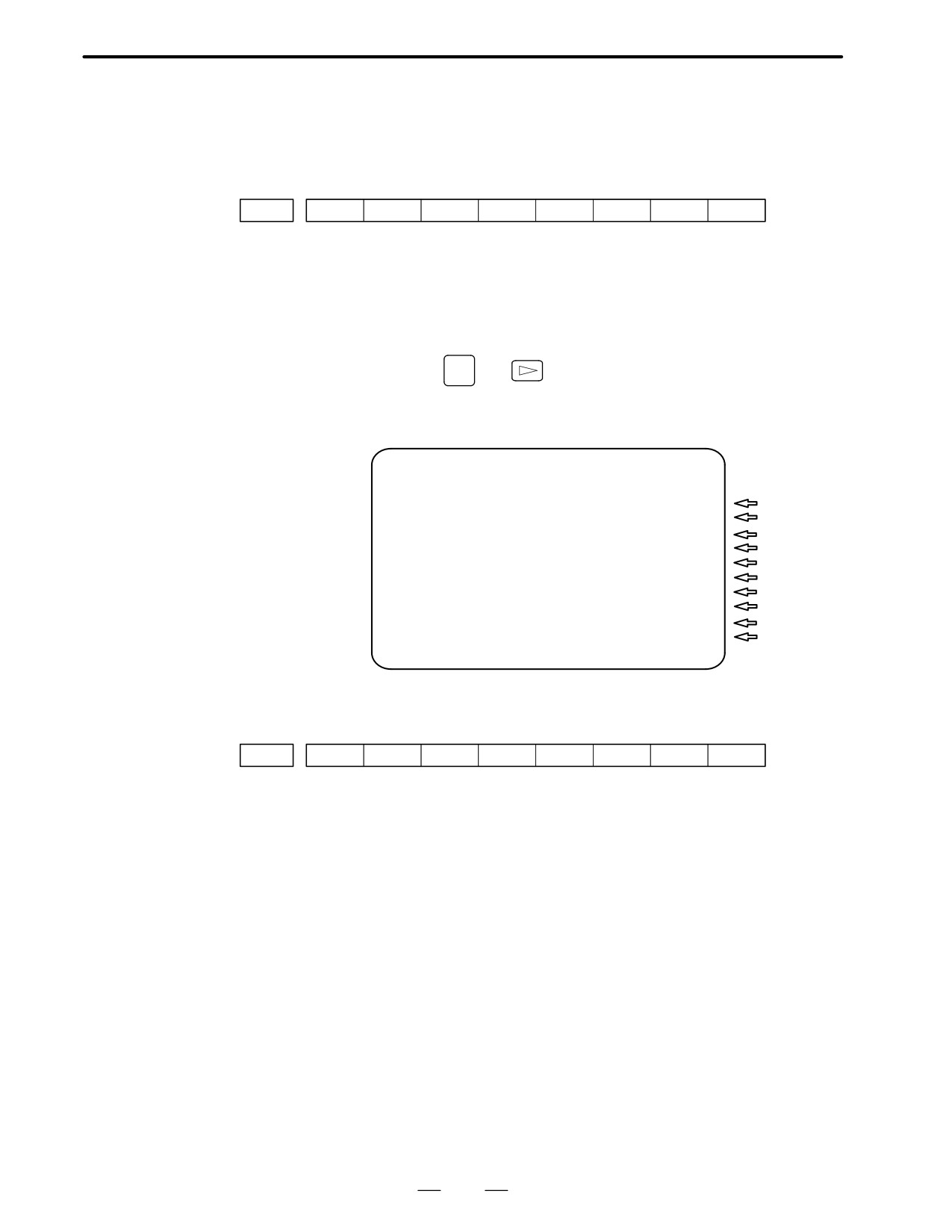
2. Set the parameter to display the servo tuning screen.
#7
#6
#5
#4
#3
#2
#1
#0
3111
SVS
#0 (SVS)
0 : Servo tuning screen is not displayed.
1 : Servo tuning screen is displayed.
3. Turn off the power once then turn it on again.
4. Display the servo parameter setting screen by the following
operation:
SYSTEM
key
[SV.PARA].
5. Input data required for initial setting using the cursor and page key.
SERVO SETTING
X AXIS
Y AXIS
(1)INITIAL SET BIT
00000000
00000000
PRM
2000
(2)MOTOR ID NO.
47
47
PRM
2020
(3)amr
00000000
00000000
PRM
2001
(4)cmr
2
2
PRM
1820
(5)FEED GEAR N
1
1
PRM
2084
(6)
(N/M) M
125
125
PRM
2085
(7)DIRECTION SET
111
111
PRM
2022
(8)VELOCITY PULSE NO.
8192
8192
PRM
2023
(9)POSITION PULSE NO. 12500
12500
PRM
2024
(10)REF.COUNTER
8000
8000
PRM
1821
(1) INITIAL SET BIT
#7
#6
#5
#4
#3
#2
#1
#0
2000
PRMCAL
DGPRM
PLC01
#3 (PRMCAL)
1 : Turns to 1 when the initial setting is done.
The following parameters are set automatically in
accordance with the no. of pulses of pulse coder:
PRM 2043(PK1V), PRM 2044(PK2V), PRM 2047(POA1),
PRM 2053(PPMAX),PRM 2054(PDDP),
PRM 2056(EMFCMP),
PRM 2057(PVPA), PRM 2059(EMFBAS),
PRM 2074(AALPH),PRM 2076(WKAC)
#1 (DGPRM)l
0 : Initial setting of digital servo parameter is done.
1 : Initial setting of digital servo parameter is not done.
#0 (PLC01)
0 : Values of parameter 2023 and 2024 are used as they are:
1 : Values of parameter 2023 and 2024 are multiplied by 10.
248
5. DIGITAL SERVO
B-62445E/03
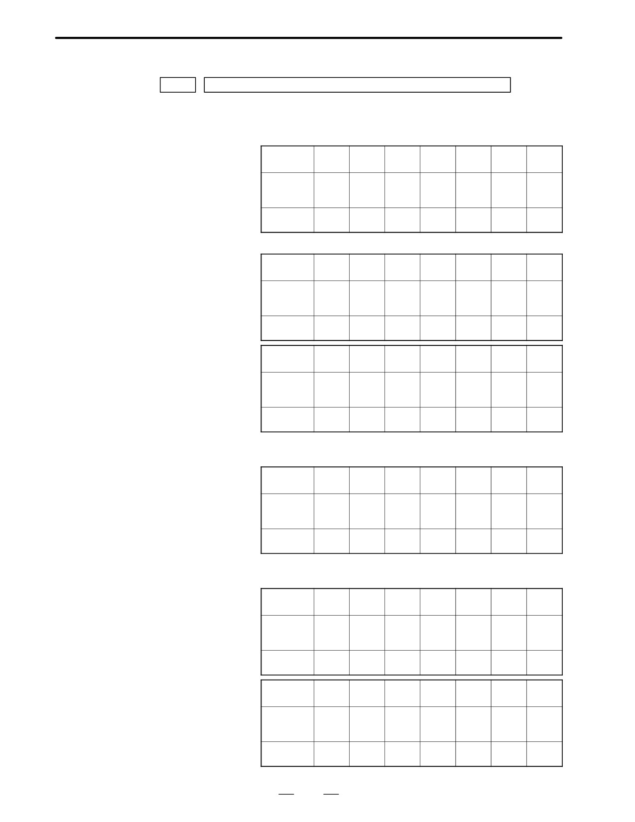
(2) MOTOR NUMBER
DGN
2020
Motor type no. per axis
Motor type no. that can be set are 15 to 26 and 39 to 84.
1
For185V input amplifier (A06B-xxxx-BVVV)
Format
42
54
56
57
58
59
60
number
Drawing
0531
0506
0561
0562
0564
0571
0572
number
(Item of xxxx)
Model
5-0
30/
0L
5L
6L
7L
10L
name
2000
2
For 200V to 230V input amplifier (A06B-xxxx-BVVV)
Format
43
44
45
46
47
48
49
number
Drawing
0532
0433
0371
0372
0313
0314
0316
number
(Item of xxxx)
Model
4-0S
3-0S
2-0SP
1-0SP
0S
5S
6S
name
Format
50
51
52
53
80
82
number
Drawing
0315
0505
0502
0590
0382
0384
number
(Item of xxxx)
Model
10S
20S/
20S
30S
5T
10T
name
1500
3
For 200V to 230V input amplifier (for large motor)
(A06B-xxxx-BVVV)
Format
39
40
41
number
Drawing
0331
0332
0333
number
(Item of xxxx)
Model
50S
60S
70S
name
4
For 200V to 230V input amplifier (for high speed motor)
(A06B-xxxx-BVVV)
Format
61
62
63
64
65
66
67
number
Drawing
0371
0373
0313
0514
0317
0318
0319
number
(Item of xxxx)
Model
2-0SP
1-0SP/
0S
5S/
10S/
20S/
30S/
name
3000
3000
3000
3000
Format
73
78
79
81
83
84
number
Drawing
0320
0583
0381
0383
0385
0374
number
(Item of xxxx)
Model
6S/
40S/
0T/
5T/
10T/
00SP
name
3000
2000
3000
3000
3000
249
5. DEGITAL SERVO
B-62445E/03
5
For 185V input amplifier (for L series high-speed motor)
(A06B-xxxx-BVVV)
Format
68
69
70
71
72
number
Drawing
0561
0562
0564
0571
0572
number
(Item of xxxx)
Model
0L/
5L/
6L/
7L/
10L/
name
3000
3000
3000
3000
2250
6
For a series(A06B-xxxx-BVVV)
Format
15
16
17
18
19
20
21
number
Drawing
0123
0127
0128
0142
0143
0147
0148
number
(Item of xxxx)
Model
α3/
α6/
α6/
α12/
α12/
α22/
α22/
name
3000
2000
3000
2000
3000
2000
3000
Format
22
23
24
25
26
number
Drawing
0152
0153
0161
0162
0163
number
(Item of xxxx)
Model
α30/
α30/
αM3
αM6
αM9
name
2000
3000
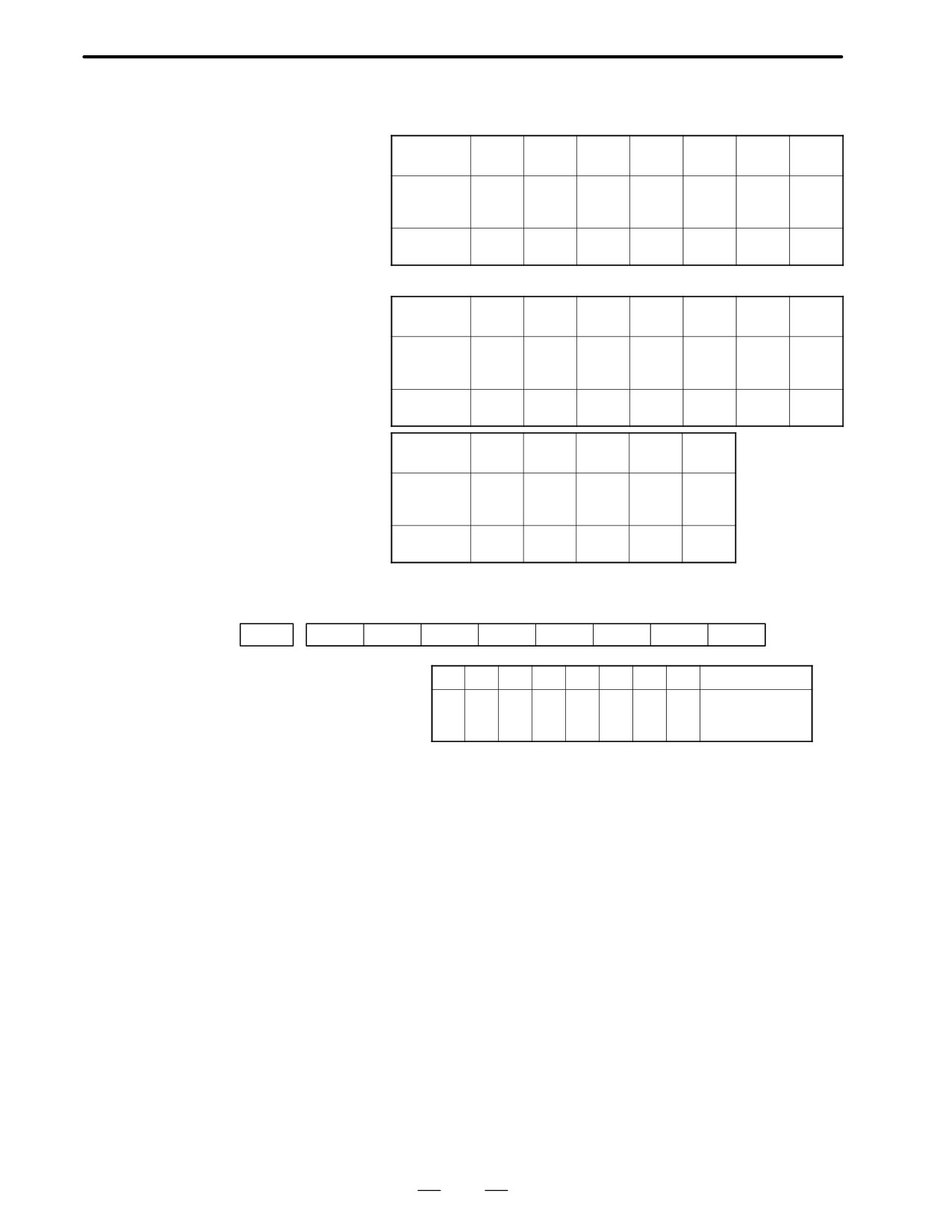
(3) ARBITARY AMR(for 5-0S to 3-0S)
#7
#6
#5
#4
#3
#2
#1
#0
PRM
2001
AMR7
AMR6
AMR5
AMR4
AMR4
AMR3
AMR2
AMR1
#7
#6
#5
#4
#3
#2
#1
#0
Motor model
1
0
0
0
0
0
1
0
5-0S
0
0
0
0
0
0
1
1
4-0S, 3-0S
0
0
0
0
0
0
0
0
other than above
Set “00000000” for serial pulse coder C.
250
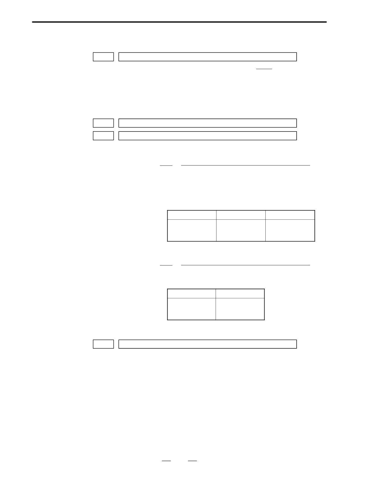
5. DIGITAL SERVO
B-62445E/03
(4) CMR
DGN
1820
Command multiply ratio
1
1
When CMR is 1/2 to 1/27
Set value=
+100
CMR
2
When CMR is 0.5 to 48
Set value=2×CMR
(5) Turn off power once, then turn it to on.
(6) Feed gear N/M
FRM
2084
n of flexible feed gear
FRM
2085
m of flexible feed gear
1
For serial pulse coder A or B, and serial a pulse coder.
No. of feedback pulses per revolution of motor
n
=
m
1000000
For serial pulse coder B, set 250,000 pulses or less to parameter 2084.
Examples
Examples of calculation
1/1000 mm
1/10000 mm
1 rotation
8mm
n=1/m=125
n=2/m=25
of motor
10mm
n=1/m=100
n=1/m=10
12mm
n=3/m=250
n=3/m=25
2
For serial pulsecoder C
No. of feedback pulses per revolution of motor
n
=
m
40000
Examples of calculation
1/1000 mm
1 rotation
8mm
n=1/m=5
of motor
10mm
n=1/m=4
12mm
n=3/m=10
(7) Direction of Travel
PRM
2022
Direction of motor rotation
111 : Positive (CCW)
-111 : Reverse (CW)
251
5. DEGITAL SERVO
B-62445E/03
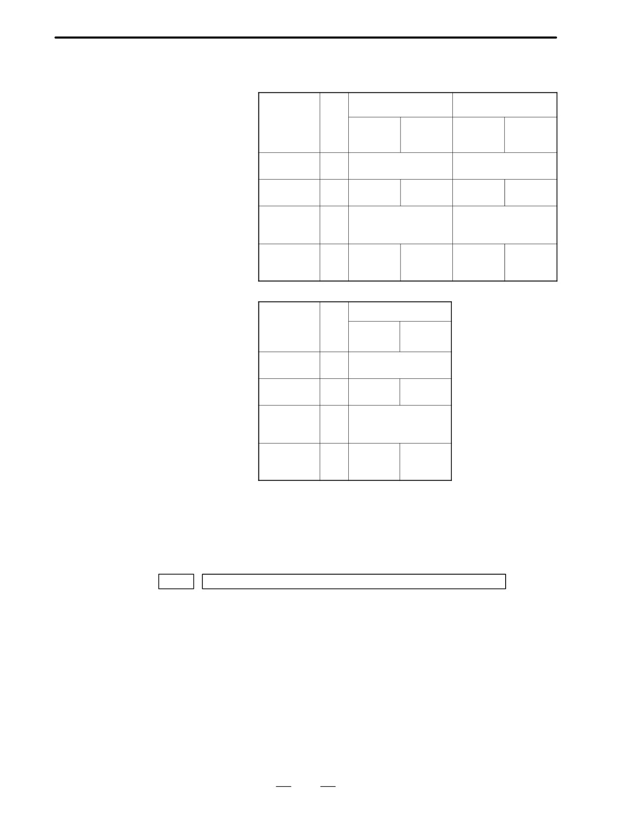
(8) No. of velocity pulses and position pulses
1
For serial pulse coder A or B and serial α pulse coder
Para
Resolution 1/1000mm
Resolution 1/10000mm
–
me-
Full close
Semi
Full close
Semi
ter
close
close
no.
High resolu-
2000
xxxx xxx 0
xxxx xxx 1
tion setting
Separate
1815
0010 0010
0010 0000
0010 0010
0010 0000
detector
Velocity
2023
8192
819
feedback
pulses
Position
2024
NS
12500
NS/10
1250
feedback
pulses
2
For serial pulse coder C
Para
Resolution 1/1000mm
–me-
ter
Full close
Semi
no.
close
High resolu-
2000
xxxx xxx1
tion setting
Separate
1815
0000
0000
detector
0010
0000
Velocity
2023
4000
feedback
pulses
Position
2024
NS/10
4000
feedback
pulses
NS is the no. of position feedback pulses times 4.
For 5-0S to 3-0S motor, since the no. of poles is different, set parameter
2001.
Even if the system is of full closed loop PMR 2002#3=1 #4=0.
(9) Reference counter
PRM
1821
Reference counter capacity(0X99999999)
6. Turn off power then turn on power.
252
5. DIGITAL SERVO
B-62445E/03
5.2
SERVO TUNING
SCREEN
5.2.1
Set a parameter to display the servo tuning screen.
Parameter Setting
#7
#6
#5
#4
#3
#2
#1
#0
3111
SVS
#0 (SVS)
0 : Servo tuning screen is not displayed.
1 : Servo tuning screen is displayed.
5.2.2
SYSTEM
1. Press
key
and soft key [SV. PARA] in this order.
Displaying Servo
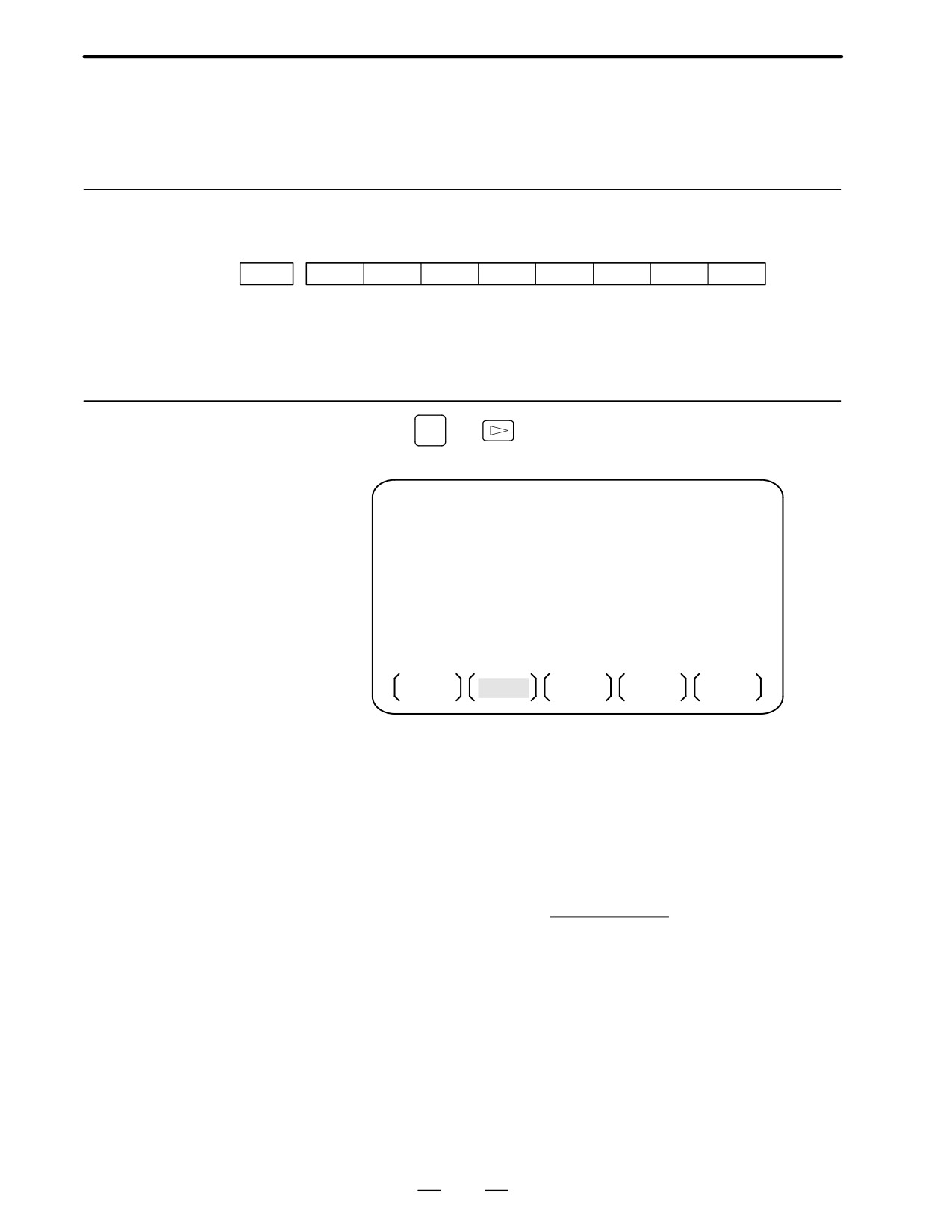
2. Press soft key [SV.TUN] to select the servo tuning screen.
Tuning Screen
SERVO TUNING
01234 N12345
(PAMAMETER)
(MONITOR)
(1)
FUN.BIT
00000000
ALARM 1
00000000
(9)
(2)
LOOP GAIN
3000
ALARM 2
00000000
(10)
(3)
TURNING SET.
0
ALARM 3
10000000
(11)
(4)
SET PERIOD
50
ALARM 4
00000000
(12)
(5)
INT.GAIN
113
ALARM 5
00000000
(13)
(6)
PROP.GAIN
-1015
LOOP GAIN
2999
(14)
(7)
FILER
0
POS ERROR
556
(15)
(8)
VELOC.GAIN
125
CURRENT%
10
(16)
SPEED RPM
100
(17)
SV SET
SV TUN
OPE
1
Function bit : PRM 2003
2
Loop gain : PRM 1825
3
Tuning start : (Used by automatic servo tuning function)
4
Set period : (Used by automatic servo tuning function)
5
Integral gain
: PRM 2043
6
Proportional gain : PRM 2044
7
Filter
: PRM 2067
(PRM 2021)+256
8
Velocity gain
Set value=
256
×100
9
Alarm 1 : DGN 200 (Details of alarm 400 and 414)
10 Alarm 2 : DGN 201 (Details of disconnection alarm, overload)
11 Alarm 3 : DGN 202 (Details of alarm 319)
12 Alarm 4 : DGN 203 (Details of alarm 319)
13 Alarm 5 : DGN 204 (Details of alarm 414)
14 Loop gain : Actual loop gain
15 Position error : Actual position error(DGN 300)
16 Current(%) : Indicate current with % to the rated value.
17 Speed RPM : Number of motor actual rotation
253
5. DEGITAL SERVO
B-62445E/03
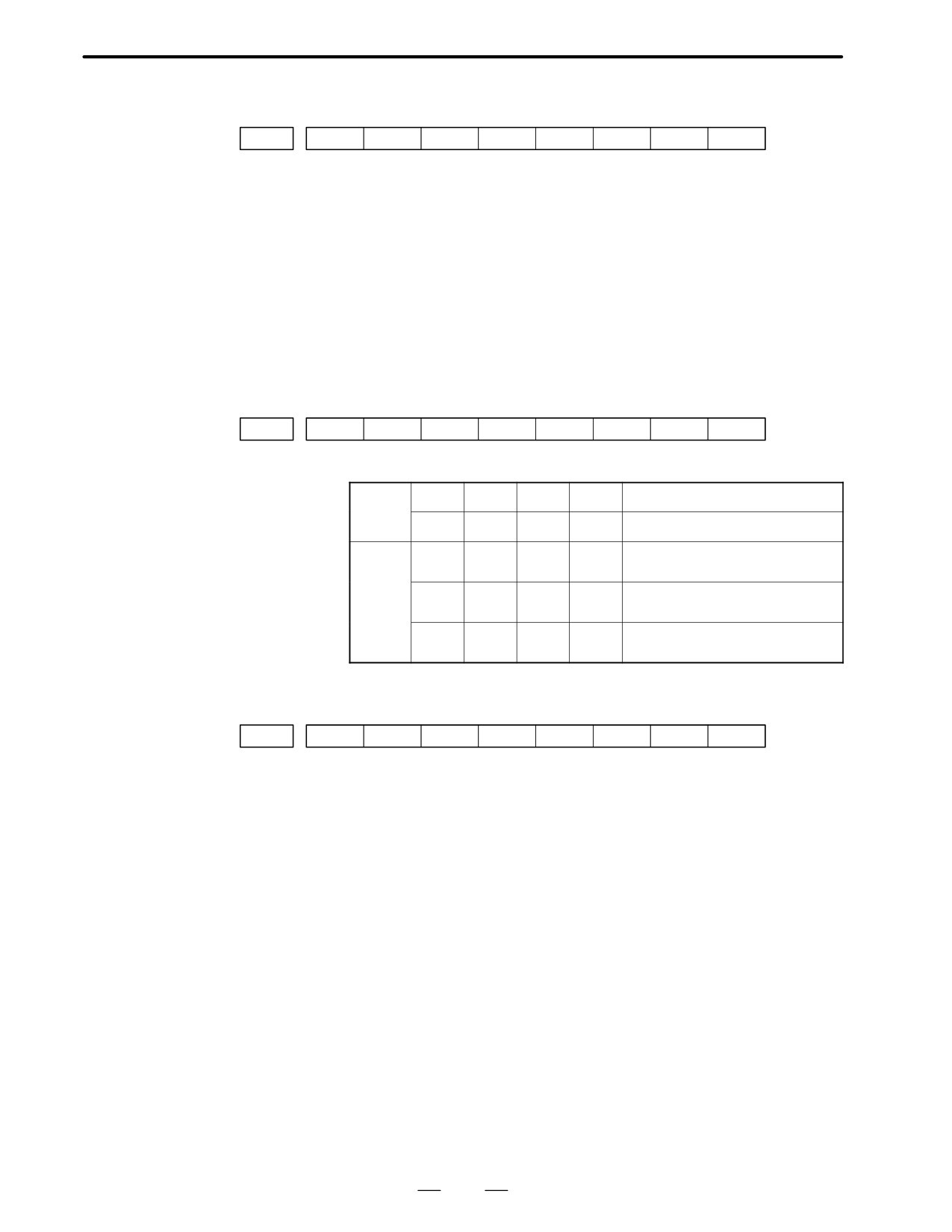
#7
#6
#5
#4
#3
#2
#1
#0
Alarm1
OVL
LV
OVC
HCA
HVA
DCA
FBA
OFA
DGN (200)
:
#7 (OVL)
:
Overload alarm
#6 (LV)
:
Insufficient voltage alarm
#5 (OVC)
:
Overcurrent alarm
#4 (HCA)
:
Abnormal current alarm
#3 (HVA)
:
Excessive voltage alarm
#2 (DCA)
:
Discharge alarm
#1 (FBA)
:
Disconnection alarm
#0 (OFA)
:
Overflow alarm
#7
#6
#5
#4
#3
#2
#1
#0
Alarm2
ALD
EXP
DGN (201) ⇓
Over-
0
—
—
—
Amplifier overheat
load
alarm
1
—
—
—
Motor overheat
Discon-
1
—
—
0
Built-in pulse coder disconnec-
nection
tion (Hardware)
alarm
1
—
—
1
Separate type pulse coder dis-
connection (Hardware)
0
—
—
0
Pulse coder disconnection (soft-
ware)
#7
#6
#5
#4
#3
#2
#1
#0
Alarm3
CSA
BLA
PHA
RCA
BZA
CKA
SPH
DGN (202)
:
#6 (CSA)
:
Hardware of serial pulse coder is abnormal.
#5 (BLA)
:
Battery voltage is in low (warning).
#4 (PHA)
:
Serial pulse coder or feedback cable is abnormal.
Counting the feedback signal is in error.
#3 (RCA)
:
Serial pulse coder is faulty.
Counting is in error.
If the RCA bit is set to 1 when both the FBA bit (bit 1 of alarm 1) and
ALD bit of alarm 2 are set to 1 and the EXP bit of alarm 2 (internal
hardware disconnection) is set to 1, a count miss alarm (CMAL)
occurs in the α pulse coder.
#2 (BZA)
:
Battery voltage becomes 0.
Replace batteries and set the reference position.
#1 (CKA)
:
Serial pulse coder is faulty.
Internal block has stopped.
#0 (SPH)
:
Serial pulse coder or feedback cable is faulty.
Counting the feedback signal is in error.
254
5. DIGITAL SERVO
B-62445E/03
#7
#6
#5
#4
#3
#2
#1
#0
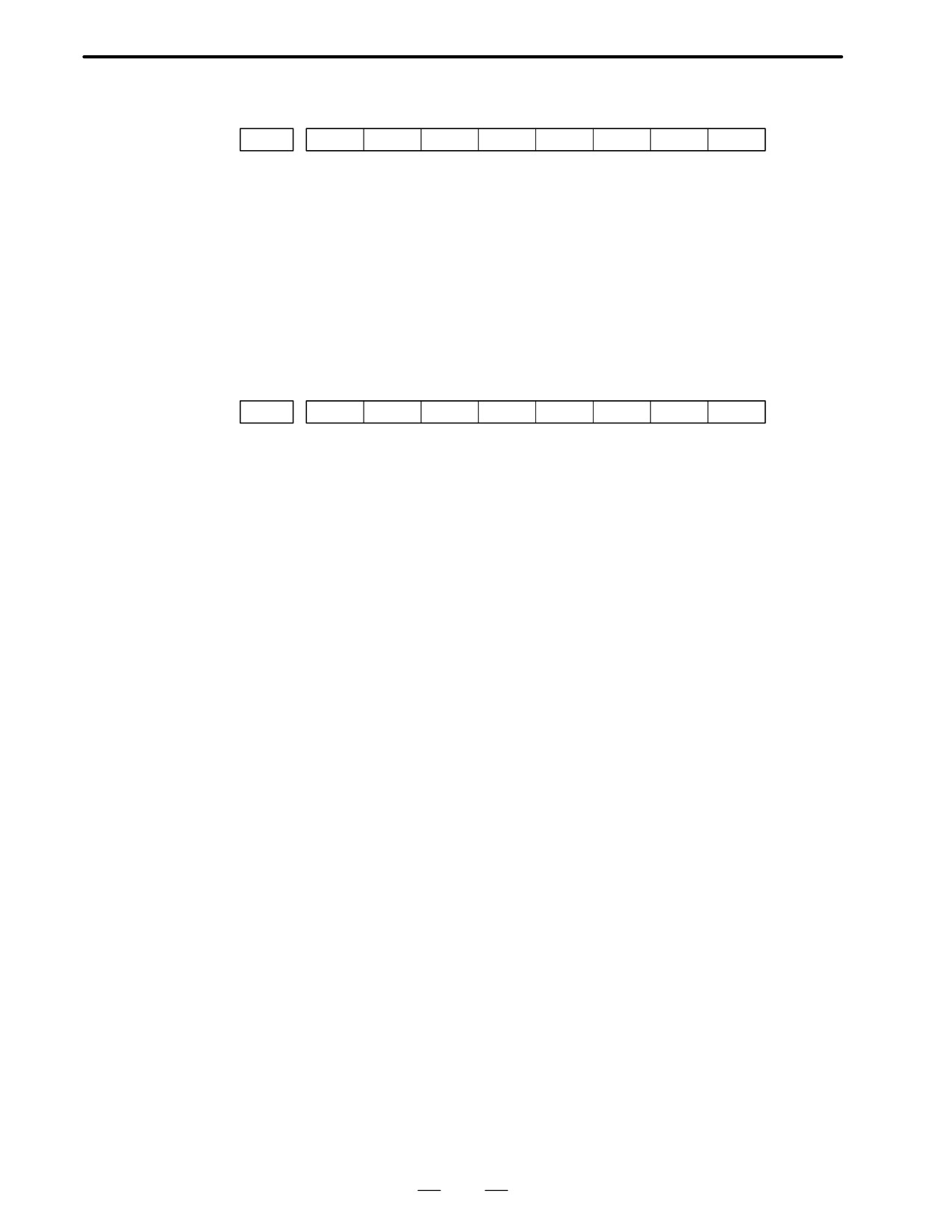
Alarm4
DTE
CRC
STB
DGN (203)
:
#7 (DTE)
:
Communication error of serial pulse coder.
There is no response.
#6 (CRC)
:
Communication error of serial pulse coder.
Transmitted data is in error.
#5 (STB)
:
Communication error of serial pulse coder.
Transmitted data is in error.
#7
#6
#5
#4
#3
#2
#1
#0
Alarm3
OFS
MCC
LDM
PMS
DGN (204)
:
#6 (OFS)
:
A/D conversion of current value of digital servo is abnormal.
#5 (MCC)
:
Contacts of electro-magnetic contactor of servo amplifier is blown
#4 (LDM)
:
LED of serial pulse coder is abnormal.
#3 (PMS)
:
No. of feedback pulses are in error because serial pulse
:
coder C or feedback cable is faulty.
255
5. DEGITAL SERVO
B-62445E/03
5.3
ADJUSTING
REFERENCE
POSITION
(DOG METHOD)
5.3.1
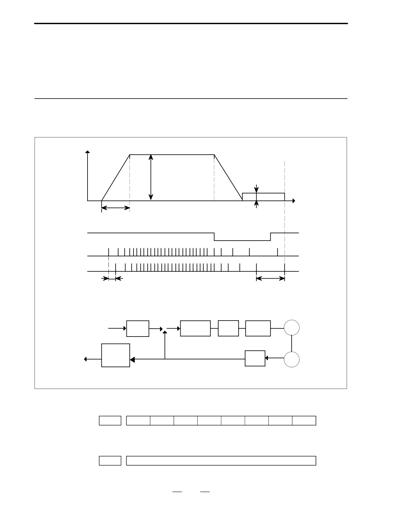
General
Speed
Rapid traverse
(PRM1420α)
FL rate
(PRM1425 α )
Time
Rapid traverse acc./dec. time constant (PRM1620 α )
*DECα
PCZ
Grid
Grid shift amount
Reference counter capacity
(PRM1850)
(PRM1821)
10mm/rev
10000P
+
Error count-
Proportion
Speed
CMR
M
gain
f
Command
er
loop
–
(Serial)
4
Refere
GRID
FFG
PC
count.
10000P/rev (Flex-
Counter capacity
ible feed gear)
10000p
D Parameter
#7
#6
#5
#4
#3
#2
#1
#0
PRM
1002
DLZ
#1(DLZ)l
0 : Reference position return method is normal (dog).
1 : Dogless reference position setting is used.
PRM
1821
Reference counter capacity
[P]
No. of feedback pulses or its division by an integer is set.
256
5. DIGITAL SERVO
B-62445E/03
PRM
1850
Grid shift amount per axis
[P]
When the resolution is 0.0001mm, set the value in the unit ten times
the detection unit.
#7
#6
#5
#4
#3
#2
#1
#0
PRM
1815
APC
APZ
OPT
#5(APC)
0 : Position detector is other than absolute pulse coder.
1 : Position detector is absolute pulse coder.
#4(APZ)
Zero position of absolute pulse coder is :
0 : Not established
1 : Established
(Turns to 1 after establishment)
To manually change the value of the APZ bit from 0 to 1 without first
returning to the reference position
when using serial pulse coder α , follow this procedure: Back up the
data with the battery and give the motor one or more turns.
Turn the power off then on again, then change the APZ bit setting
from 0 to 1.
#1(OPT)
0 : Position detection is performed by the pulse coder built in the motor.
1 : Separate type pulse coder or linear scale is used.
D Separate Type Pulse
Coder or Linear Scale is
Used
PRM
1821
Reference counter capacity per axis
[P]
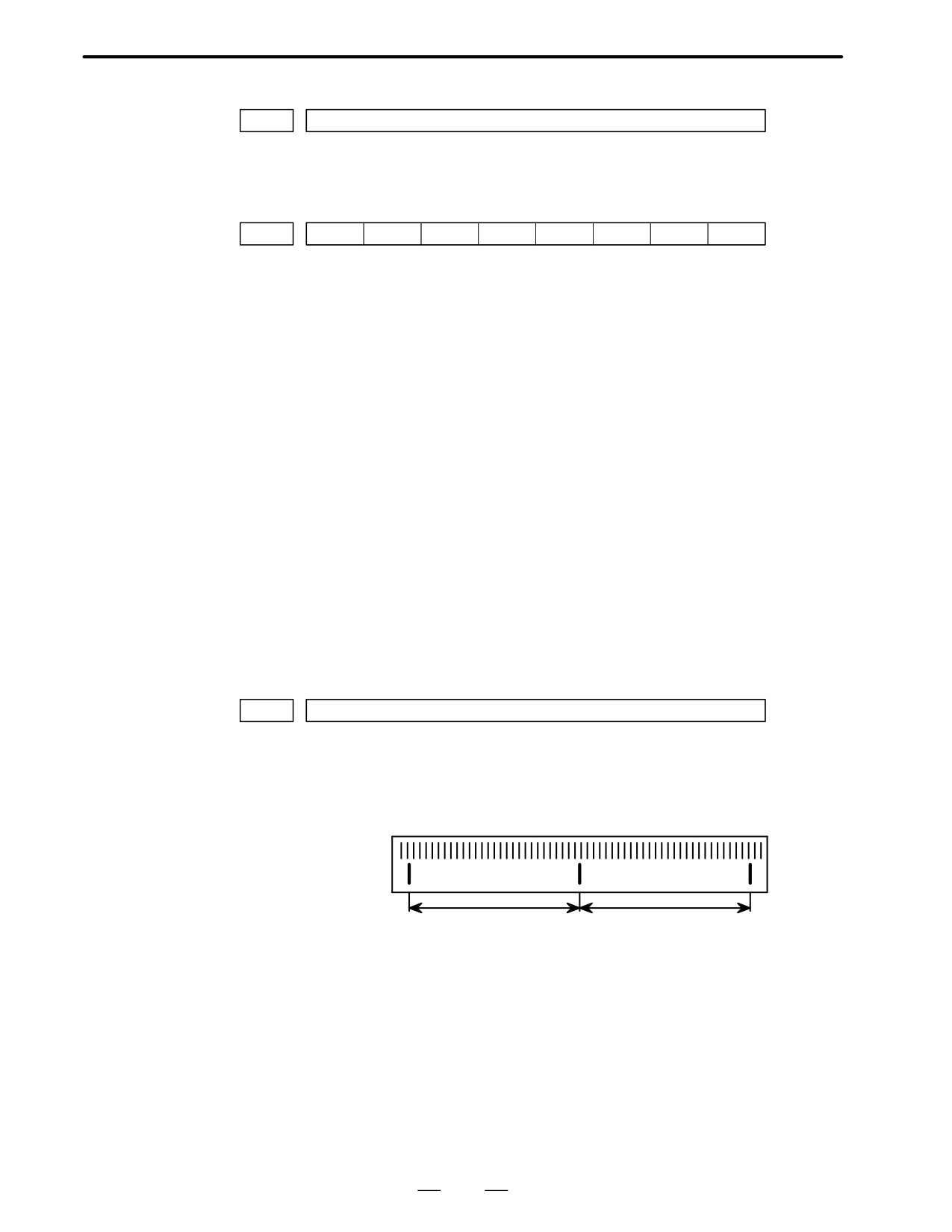
Normally, the number of feedback pulses per motor revolution is set to
the reference counter capacity.
When plural reference marks are on a linear scale, a quotient of the
distance between the reference marks divided by an interfer may be used
as a reference counter capacity:
Example
(1µ m)
300mm ⇒ reference counter
30000
20000
15000
10000 etc
257
5. DEGITAL SERVO
B-62445E/03
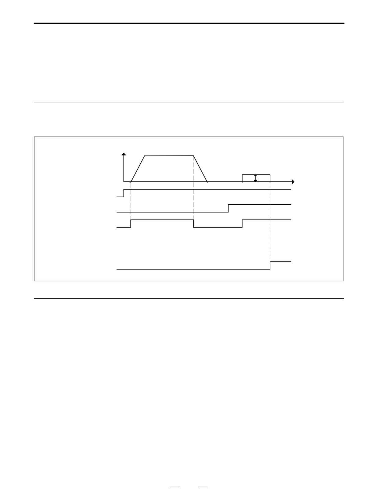
When there are no dog nor limit switch for reference position return, this
5.4
function enables the tool to return the reference position that is set by
DOGLESS
MTB.
REFERENCE
When the absolute position detector is used, the reference position once
POSITION SETTING
set remains also during power off. When the absolute detector is replaced
or absolute position is lost, perform this setting.
5.4.1
General
Speed
Reference position return
FL rate (PRM 1425)
Time
JOG
ZRN
+Jα
GRID
ZP α
5.4.2
Operation
1
Move the tool near the reference position using a manual operation.
2
Select the reference position return mode or switch.
3
Press a button for an axis-and-direction-select-signal + or -, and the
machine moves to the next grid, then stops.
(This position is set as the reference position).
After the reference position has been set, select the reference position
return mode(SRN signal is 1) and turn on an axis-and-direction-
select signal, then the tool returns to the reference position.
258
5. DIGITAL SERVO
B-62445E/03
5.4.3
Associated Parameters
#7
#6
#5
#4
#3
#2
#1
#0
PRM
1002
DLZ
#1(DLZ)
0 : Dog is used for reference position return
l 1 : Dogless reference position setting
#7
#6
#5
#4
#3
#2
#1
#0
PRM
1006
ZMI
#5(ZMI)
0 : Reference position return and backlash initial direction is +.
1 : Reference position return and backlash initial direction is -.
After ZRN signal becomes 1, manual feed direction is always the
direction set by this parameter irrespective of an axis selection signal.
259

6. AC SPINDLE (SERIAL INTERFACE)
B-62445E/03
AC SPINDLE (SERIAL INTERFACE)
6
This chapter describes the parameter tuning screen of serial interface
spindle amplifier.
6.1 GENERAL OF SPINDLE CONTROL
(SERIAL* INTERFACE) .
261
6.2 TABLE OF TEST POINTS .
263
6.3 CONFIRMING POWER SUPPLY
(SERIAL INTERFACE) .
266
6.4 SPINDLE SETTING AND TUNING SCREEN .
269
6.5 AUTOMATIC SETTING OF STANDARD
PARAMETERS .
277
On the serial interface spindle amplifier, the following specification
number is printed on upper part of the spindle unit
A06B-6063-Hxxx or
A06B-6064-Hxxx or
A06B-6065-Hxxx
(xxx is any)
Refer to the following manuals for maintenance of FANUC AC
SPINDLE MOTOR α series :
1) FANUC CONTROL MOTOR α series MAINTENANCE MANUAL
(B-65165E)
2) FANUC AC SPINDLE MOTOR α series PARAMETER MANUAL
(B-65160E)
260
6. AC SPINDLE (SERIAL INTERFACE)
B-62445E/03
6.1
GENERAL OF
SPINDLE CONTROL
(SERIAL*
INTERFACE)
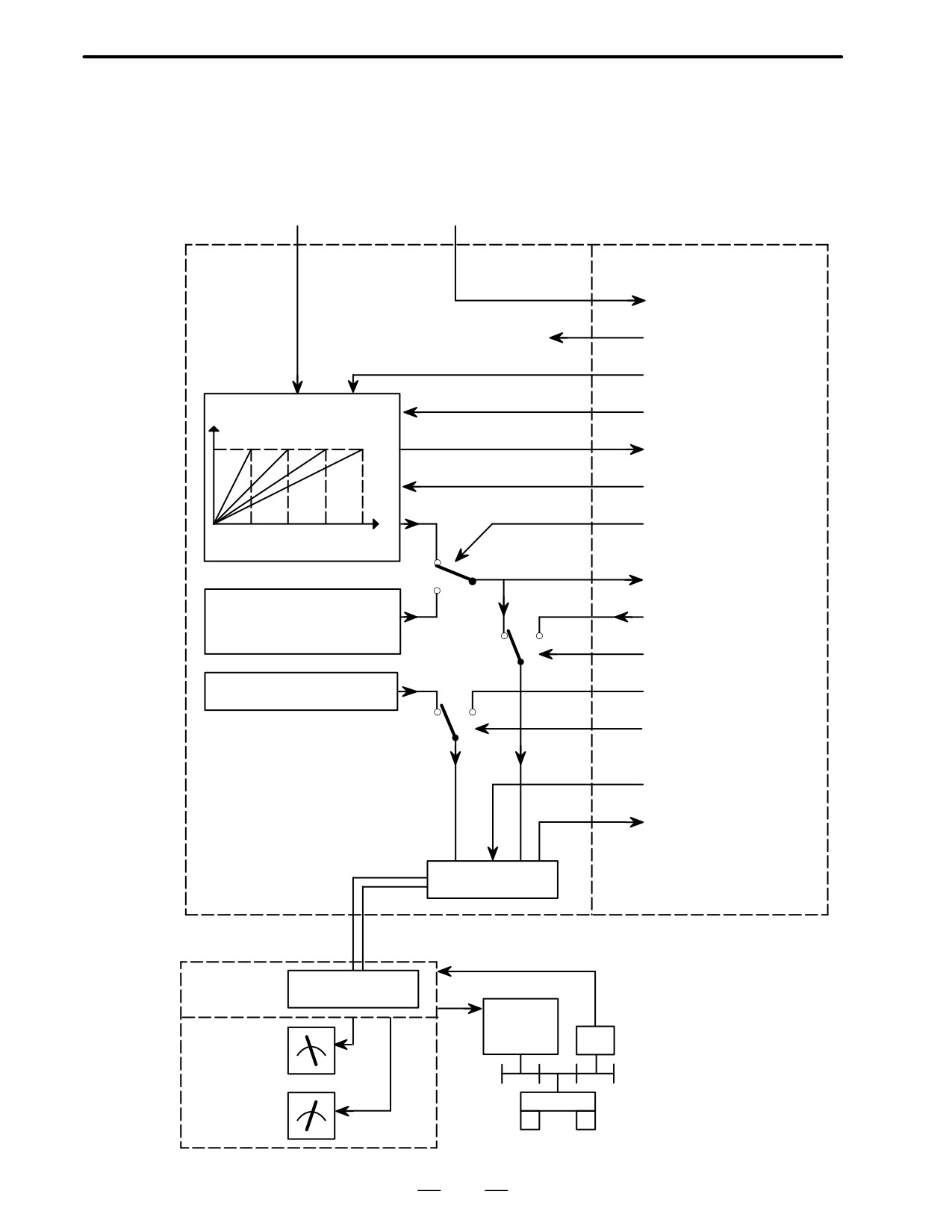
S instruction
M instruction
NC
PMC
M03,M04,M05,M19
FIN
*SSTP(Spindle stop)
SOVx( Spindle override)
Motor speed
SF,GR10,GR20,GR30
(For milling machine)
GR1,GR2 (For lathe)
S
SOR( Orientation)
(PRM 3735X3752)
0
R010XR120
1
Orientation speed
(PRM 3705#1, 3732,
R01IXR12I
0
1
3706#5)
SIND
Output polarity
SGN(0=+,1=-)
(PRM 3706#7,6)
0
1
SSIN
*ESP,MRDY,
SFR,SRV,ORCM
etc.
SST, SDT, SAR, LDT1,
LDT2
ORAR, ALM etc.
Interface
function
Optical cable
Serial spindle
Interface
amplifier
function
Spindle
Operator’s
motor
panel
PC
Load meter
LM
Spindle
Speed meter
SM
261
6. AC SPINDLE (SERIAL INTERFACE)
B-62445E/03
6.1.1
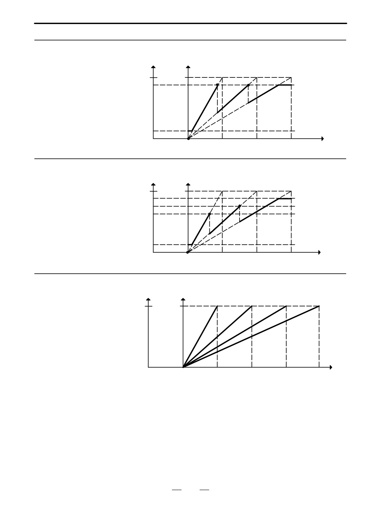
Output
Motor speed
Method A of Gear
Change for Machining
4095
Max
Center
PRM 3736
Gear 2
Gear 3
Gear 1
PRM 3735
0
S code
0 PRM 3741 PRM 3742 PRM 3743
6.1.2
Output
Motor speed
Method B of Gear
change for Machining
4095
Max
Center(PRM 3705#2=1)
PRM 3736
Gear 1
Gear 2
Gear 3
PRM 3735
0
S code
0 PRM 3741 PRM 3742 PRM 3743
6.1.3
Output Motor speed
For Lathe
4095
Max
Gear 2
Gear 3
Gear 1
Gear 4
S code
0
0 PRM 3741 PRM 3742 PRM 3743 PRM 3744
262
6. AC SPINDLE (SERIAL INTERFACE)
B-62445E/03
6.2
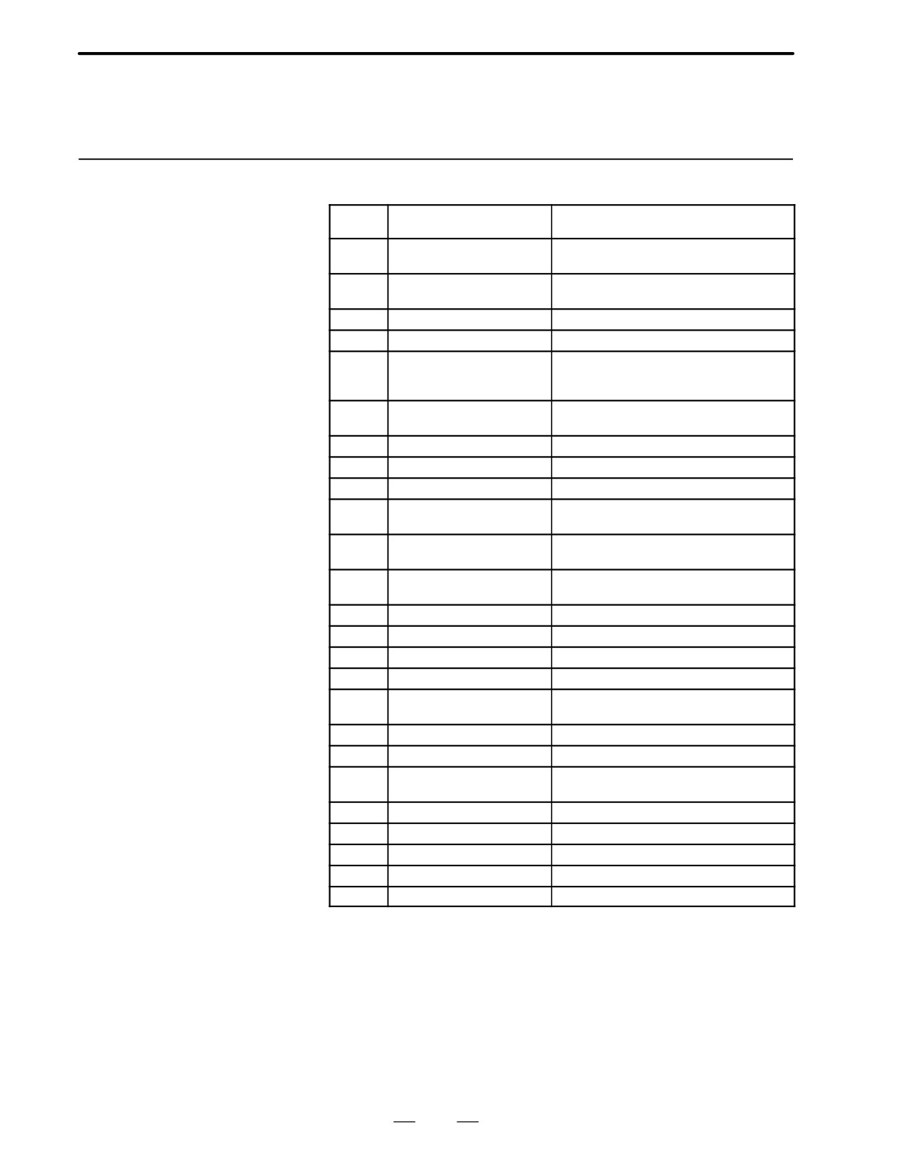
TABLE OF TEST
POINTS
6.2.1
Printed Circuit Board
Name
Signal
Remarks
(A16B-2201-0440)
PA
Pulse-generator phase A
90°advance for PB in a CW rotation
Vpp=0.36X0.5V
PB
Pulse-generator phase B
90° delay for PA in a CW rotation
Vpp=0.36X0.5V
RA
Phase-A reference voltage
DC +2.5VX0.2V
RB
Phase-B reference voltage
DC +2.5VX0.2V
PAAS
Signal with the amplitude 10
90° advance for PB in a clockwise direc-
times that of PA
tion,Vp-p=3.6 to 0.5V
PBAS
Signal with the amplitude 10
90 delay for PA in a clockwise direc-
times that of PB
tion,Vp-p=3.6V to 5.0V
PAA
A phase pulse waveform
Duty 50%
(ON/ OFF ratio)
PBA
B phase pulse waveform
Duty 50%
(ON/ OFF ratio)
*ITP1
ITP pulse
Synchronous signal from the CNC
TR
Serial data transmission sig-
The high level of this signal indicates that se-
nal
rial data is being transmitted from the CNC
MSA
Magnetic sensor output
One signal per rotation
MSA signal
LSA
Magnetic sensor output
One signal per rotation
LAS signal
*LS
LSA pulse signal
One signal per rotation
PAE2
Position-coder phase A
Duty 50%
(ON/ OFF ratio)
PBE2
Posiiton-coder phase B
Duty 50%
(ON/ OFF ratio)
PSE2
Position-coder phase Z
1 pulse/rotation
*PELS
Position coder cable is bro-
The low level of this signal indicates that the
ken
wire is broken.
CLK1
Clock signal
8MHz, 50% duty
VDC
DC link voltage signal
Voltage that is 1/100 of the DC link voltage
SDC
Control power DC link voltage
Voltage that is 1/100 of the DC voltage of the
signal
input power
+24V
+24V DC voltage
+20V to +26V
+15V
+15V DC voltage
+15V ±4%
+5V
+5V DC voltage
+5V±%
–15V
-15V DC voltage
-15V±4%
0V
263
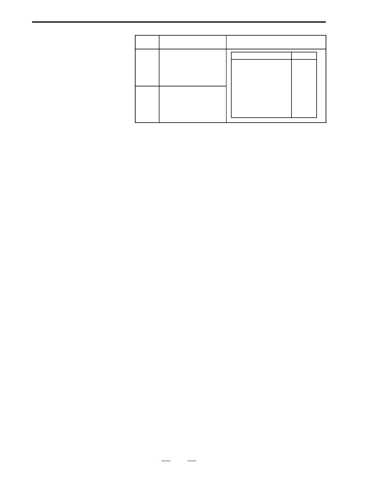
6. AC SPINDLE (SERIAL INTERFACE)
B-62445E/03
Name
Signal
Remarks
IU
U-phase current detection
Amplifier
Current
signal
Model 1SX3S
21.9A/V
Model small 6S,6SX12S
33.3A/V
Model 15S
41.7A/V
Model 15SX22S
66.7A/V
Model 26S
83.3A/V
IV
V-phase current detection
Model Small 30S
111.1A/V
signal
Model 30S
83.3A/V
Model 40S
104.2A/V
Model 30HV,40HV
50.5A/V
Model 60HV
94.7A/V
264
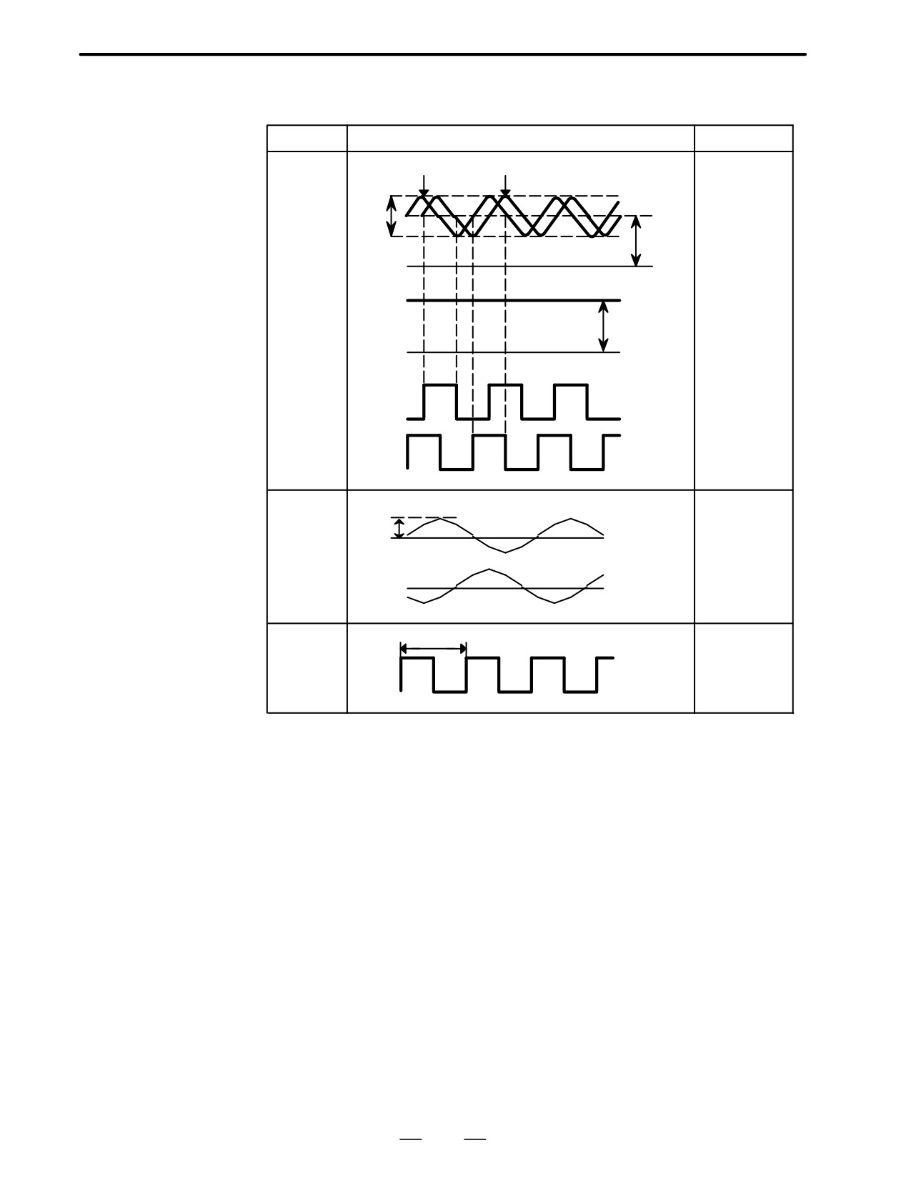
6. AC SPINDLE (SERIAL INTERFACE)
B-62445E/03
6.2.2
Signal Waveform
Check terminal
Waveform
Remarks
At Test Points
PB
PA
Pulse generator
output
PA
0.36
+2.5V
PB
X0.5
Phase differ-
ence between
V
PA and PB is
0V
90°
RA
2.5V"0.2V
RB
Nominal
0V
voltage
+4X+4.5V
PAA
0V
0V
PBA
Signal formed
by PA/PB
Peak
Current feed-
IU
0V
back signal of
each phase
IV
Peak value is
0V
proportional to
current value
125ns
+4V
Clock
CLK1
8MHz
0V
265
6. AC SPINDLE (SERIAL INTERFACE)
B-62445E/03
6.3
CONFIRMING POWER
SUPPLY
(SERIAL INTERFACE)
6.3.1
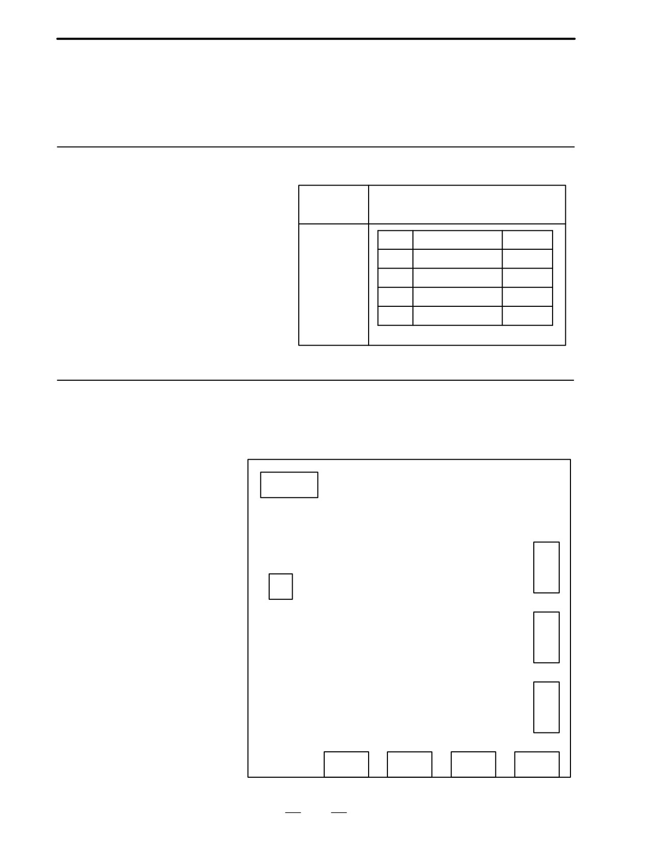
Confirm AC power voltage and DC current on spindle control circuit PCB
as follows:
Power Supply
AC power supply
Check terminals R,S,T,G
DC voltage
Volt
Test points
Rated value
on spindle
control circuit
+24V
Across +24V to 0V
+20X+26V
PCB
+15V
Across +15V to 0V
+15V"4%
+5V
Across +5V to 0V
+5V"2%
–15V
Across -15V to 0V
-15V"4%
6.3.2
Test Points
D A20B-1003-0550
CN10
Ę Ę Ę
+B
-B
0B
Ę 0V
C
N
6
Ę
ST
C
N
5
+24V Ę Ę
0V
+5V
Ę Ę 0V
+15V
Ę Ę-15V
0V Ę
C
N
4
CN11A
CN11B
CN2
TB
266
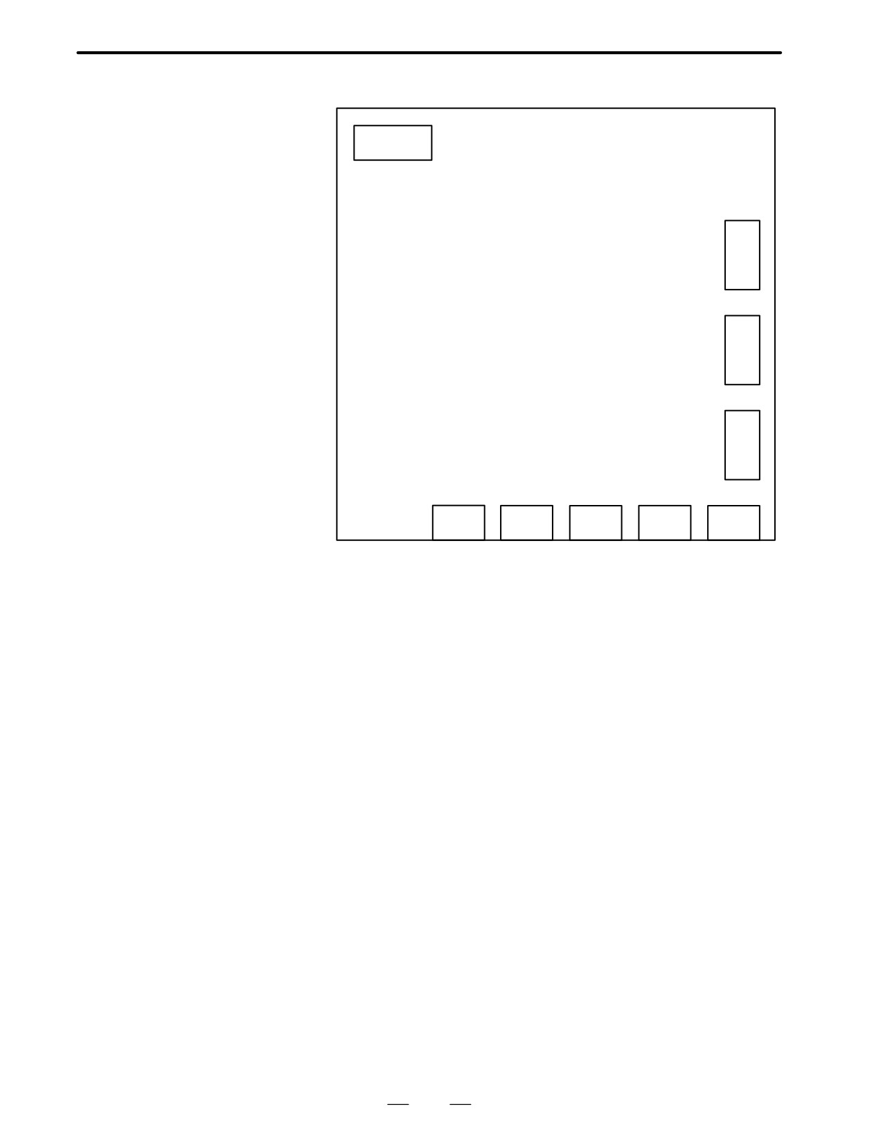
6. AC SPINDLE (SERIAL INTERFACE)
B-62445E/03
D A20B-1003-0920
CN10
Ę Ę Ę
+B
-B
0B
Ę 0V
C
N
6
C
N
5
+24V Ę
Ę 0V
+5V Ę
+15V Ę Ę
0V
Ę -15V
C
0V Ę Ę
0V
N
4
CN13
CN11A
CN11B
CN2
TB
267
6. AC SPINDLE (SERIAL INTERFACE)
B-62445E/03
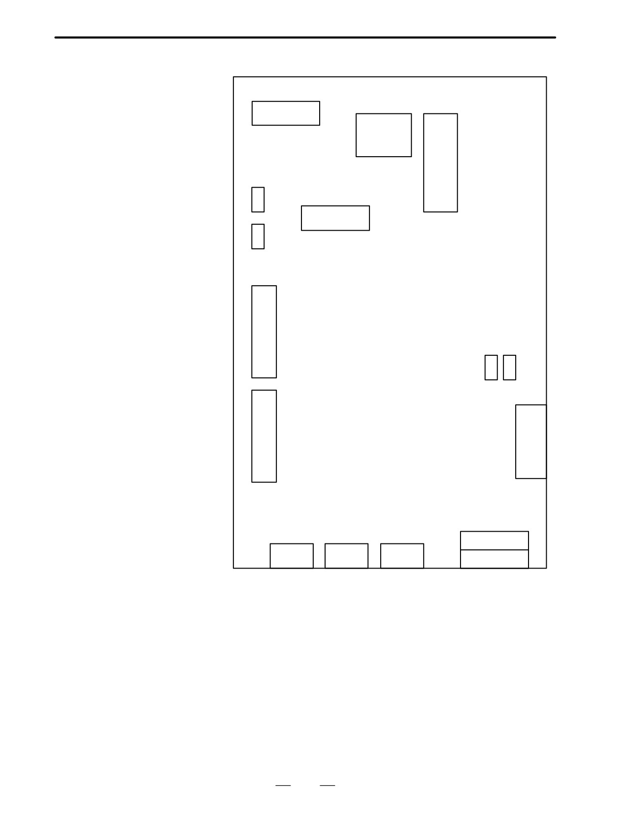
D A16B-2201-0010
A16B-2201-0440
0V +24V +15V -15V +5V
Ę Ę Ę Ę Ę
Display part
Setting
switch
ROM
ST2
CN10
ST1
C
N
12
S2 S3
C
N
TB
14
CNA/TOP
CN13
CN11A
CN11B
CN2/BOTTOM
268