FANUC Series 16 / 160 / 18 / 180 – Model B. Maintenance Manual - page 6
2. HARDWARE
B-62445E/03
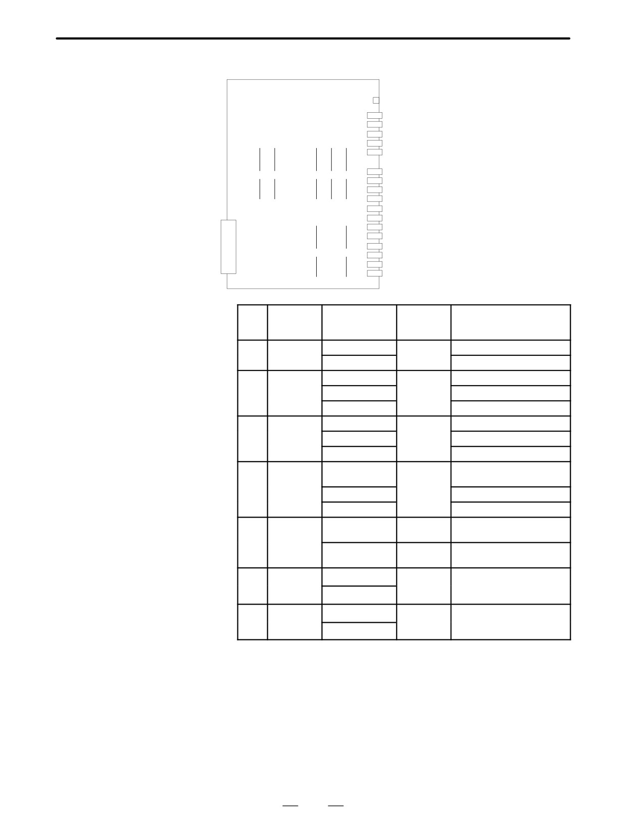
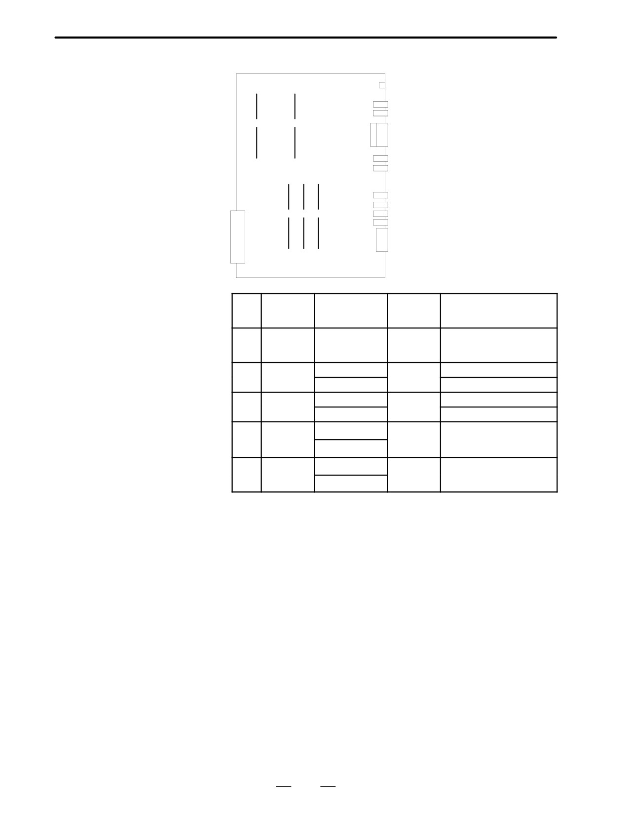
D Location of modules
Connector Connector
A16B-2202-0890, 0891
name
number Use
LED
HDI
JA5
High-speed skip signal
A-1N
JA6
Analog input
SPDL-2
JA7B
Serial spindle
A-OUT2 JA8B
Analog output
APCBAT JA4B
Battery for use with the APC
AMP5
JV5
Axis 5 servo amplifier
(1)
(2)
(3)
(4)
(5)
AMP6
JV6
Axis 6 servo amplifier
AMP7
JV7
Axis 7 servo amplifier
AMP8
JV8
Axis 8 servo amplifier
ENC5
JF5
Axis 5 pulse coder
ENC6
JF6
Axis 6 pulse coder
ENC7
JF7
Axis 7 pulse coder
ENC8
JF8
Axis 8 pulse coder
SCALE5 JF25
Axis 5 scale
(6)
(7)
SCALE6 JF26
Axis 6 scale
SCALE7 JF27
Axis 7 scale
SCALE8 JF28
Axis 8 scale
No.
Name
Specifications
Function
Display of system
configuration screen
(1)
FROM
A20B-2902-0081
2nd path
FLASH ROM MODULE:4MB
module
macro
A20B-2902-0082
FLASH ROM MODULE:2MB
(2)
SRAM
A20B-2902-0350
CNC
ADDITIONAL SRAM: 256KB
module
expanded
A20B-2902-0351
ADDITIONAL SRAM: 768KB
RAM
A20B-2902-0352
ADDITIONAL SRAM: 2.25MB
(3)
DRAM
A20B-2901-0940
CNC
DRAM:6MB
module
system
A20B-2901-0941
DRAM:4MB
RAM
A20B-2901-0942
DRAM:2MB
(4)
Spindle
A20B-2901-0984
Spindle
SERIAL SPINDLE LSI
module
control
ANALOG SPINDLE LSI
A20B-2901-0985
SERIAL SPINDLE LSI
A20B-2901-0986
ANALOG SPINDLE LSI
(5)
HAM
A20B-2900-0280
Analog
H-SKIP DI & ANALOG I/O:
module
I/O+HDI
HDI+ANALOG
A20B-2900-0281
HDI
H-SKIP DI & ANALOG I/O:
HDI
(6)
Servo
A20B-2902-0060
Servo con-
SERVO 7/8 AXIS
module
trol 7th or
A20B-2902-0061
8th axis
(7)
Servo
A20B-2902-0060
Servo con-
SERVO 5/6 AXIS
module
trol 5th or
A20B-2902-0061
6th axis
145
2. HARDWARE
B-62445E/03
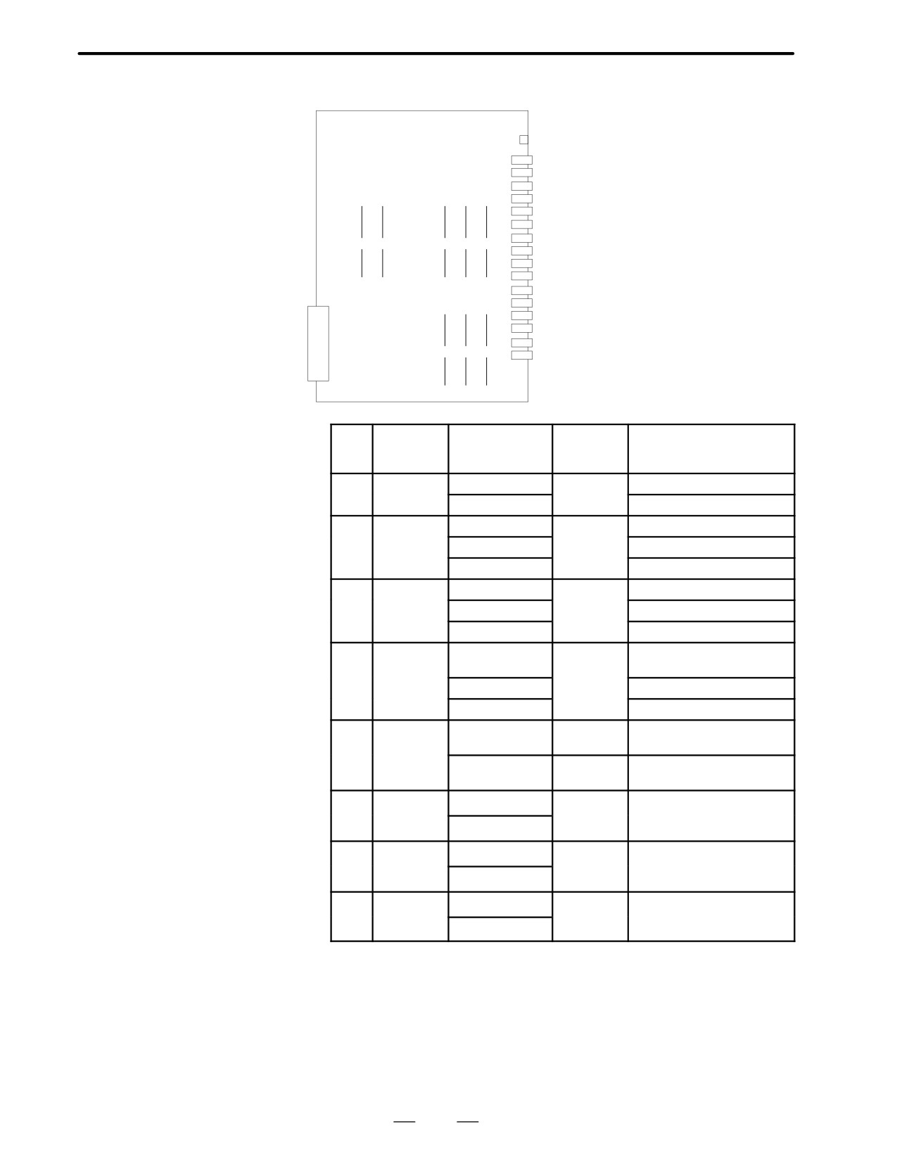
D Location of modules
Connector Connector
A16B-2202-0850, 0851
name
number Use
LED
HDI
JA5
High-speed skip signal
A-IN
JA6
Analog input
SPDL-2
JA7B
Serial spindle
A- OUT2 JA8B
Analog output
APCBAT JA4B
Battery for use with the APC
AMP1
JS1A-2
Axis 1 servo amplifier
AMP2
JS2A-2
Axis 2 servo amplifier
(1)
(2)
(3)
(4)
(5)
AMP3
JS3A-2
Axis 3 servo amplifier
AMP4
JS4A-2
Axis 4 servo amplifier
AMP5
JS5A-2
Axis 5 servo amplifier
AMP6
JS6A-2
Axis 6 servo amplifier
SCALE1 JF21-2
Axis 1 scale
SCALE2 JF22-2
Axis 2 scale
SCALE3 JF23-2
Axis 3 scale
SCALE4 JF24-2
Axis 4 scale
(6)
(7)
(8)
SV- CHK JA8C
Servo check
No.
Name
Specifications
Function
Display of system
configuration screen
(1)
FROM
A20B-2902-0081
2nd path
FLASH ROM MODULE:4MB
module
macro
A20B-2902-0082
FLASH ROM MODULE:2MB
(2)
SRAM
A20B-2902-0350
CNC
ADDITIONAL SRAM: 256KB
module
system
A20B-2902-0351
ADDITIONAL SRAM: 768KB
RAM
A20B-2902-0352
ADDITIONAL SRAM: 2.25MB
(3)
DRAM
A20B-2901-0940
CNC
DRAM:6MB
module
system
A20B-2901-0941
DRAM:4MB
RAM
A20B-2901-0942
DRAM:2MB
(4)
Spindle
A20B-2901-0984
Spindle
SERIAL SPINDLE LSI
module
control
ANALOG SPINDLE LSI
A20B-2901-0985
SERIAL SPINDLE LSI
A20B-2901-0986
ANALOG SPINDLE LSI
(5)
HAM
A20B-2900-0280
Analog
H-SKIP DI & ANALOG I/O:
module
I/O+HDI
HDI+ANALOG
A20B-2900-0281
HDI
H-SKIP DI & ANALOG I/O:
HDI
(8)
Servo
A20B-2902-0060
Servo con-
SERVO 5/6 AXIS
module
trol 5th or
A20B-2902-0061
6th axis
(7)
Servo
A20B-2902-0060
Servo con-
SERVO 3/4 AXIS
module
trol 3rd or
A20B-2902-0061
4th axis
(8)
Servo
A20B-2902-0060
Servo con-
SERVO 1/2 AXIS
module
trol 1st or
A20B-2902-0061
2nd axis
146
2. HARDWARE
B-62445E/03
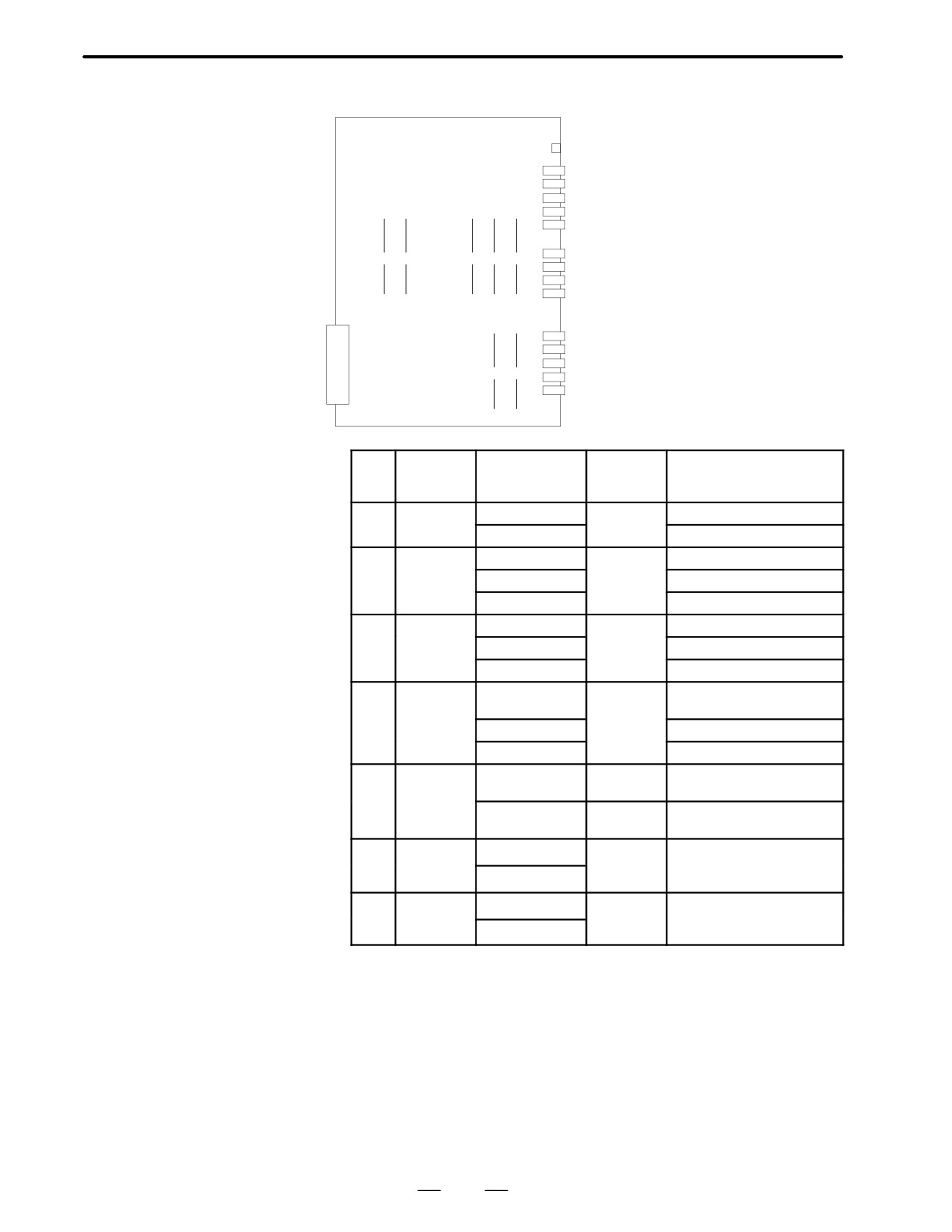
D Location of modules
Connector Connector
A61B-2202-0853
name
number Use
LED
HDI
JA5
High-speed skip signal
A-IN
JA6
Analog input
SPDL-2
JA7B
Serial spindle
A-OUT2
JA8B
Analog output
APCBAT JA4B
Battery for use with the APC
AMP1
JS1A-2
Axis 1 servo amplifier
(1)
(2)
(3)
(4)
(5)
AMP2
JS2A-2
Axis 2 servo amplifier
AMP3
JS3A-2
Axis 3 servo amplifier
AMP4
JS4A-2
Axis 4 servo amplifier
SCALE1 JF21-2
Axis 1 scale
SCALE2 JF22-2
Axis 1 scale
SCALE3 JF23-2
Axis 1 scale
(6)
(7)
SCALE4 JF24-2
Axis 1 scale
SV-CHK JA8C
Servo check
No.
Name
Specifications
Function
Display of system
configuration screen
(1)
FROM
A20B-2902-0081
2nd path
FLASH ROM MODULE:4MB
module
macro
A20B-2902-0082
FLASH ROM MODULE:2MB
(2)
SRAM
A20B-2902-0350
CNC
ADDITIONAL SRAM: 256KB
module
system
A20B-2902-0351
ADDITIONAL SRAM: 768KB
RAM
A20B-2902-0352
ADDITIONAL SRAM: 2.25MB
(3)
DRAM
A20B-2901-0940
CNC
DRAM:6MB
module
system
A20B-2901-0941
DRAM:4MB
RAM
A20B-2901-0942
DRAM:2MB
(4)
Spindle
A20B-2901-0984
Spindle
SERIAL SPINDLE LSI
module
control
ANALOG SPINDLE LSI
A20B-2901-0985
SERIAL SPINDLE LSI
A20B-2901-0986
ANALOG SPINDLE LSI
(5)
HAM
A20B-2900-0280
Analog
H-SKIP DI & ANALOG I/O:
module
I/O+HDI
HDI+ANALOG
A20B-2900-0281
HDI
H-SKIP DI & ANALOG I/O:
HDI
(6)
Servo
A20B-2902-0060
Servo con-
SERVO 3/4 AXIS
module
trol 3rd or
A20B-2902-0061
4th axis
(7)
Servo
A20B-2902-0060
Servo con-
SERVO 1/2 AXIS
module
trol 1st or
A20B-2902-0061
2nd axis
147
2. HARDWARE
B-62445E/03
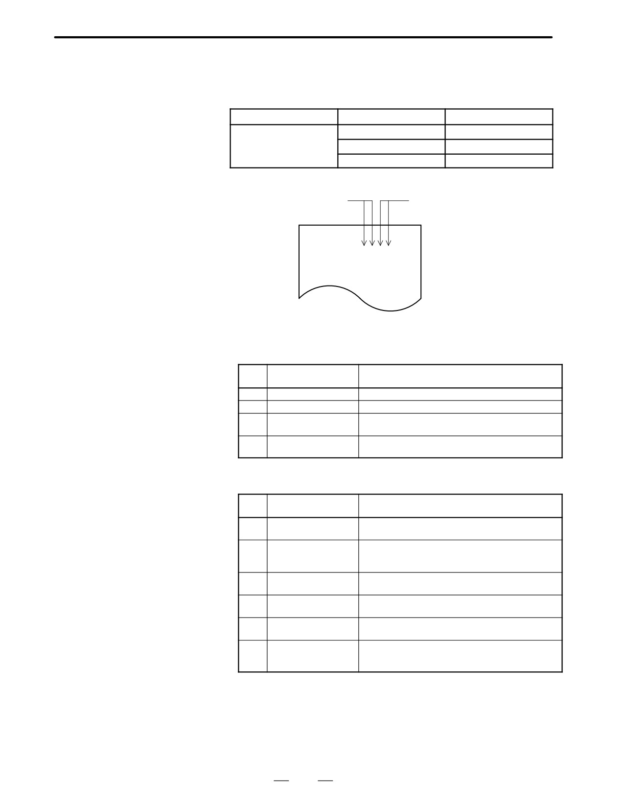
2.5.5
Option 3 board
Name
Specifications
Function
Option 3 board
A16B-3200-0054
PMC-RC
A16B-3200-0055
PMC-RC+CAP
A16B-3200-0057
CAP
D LED display
Status display of CAP-II function
Status display of
PMC-RC function
STATUS jjjj
ALARM jjj
⋅
LED display of PMC-RC function
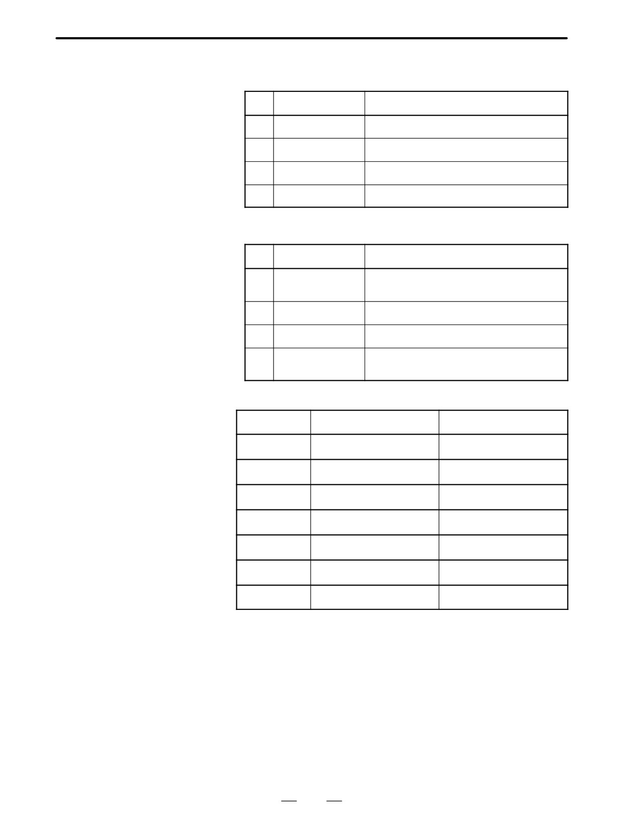
(i) LED display transition when the power is turned on
j: OFF, J:ON, z:Don’t care, l: Blink
No.
LED display
NC statue
1
STATUS JJzz
Startup status immediately after power is turned on
2
STATUS jJzz
Waiting for each processor in the system to set its ID
3
STATUS Jjzz
Waiting for each processor in the system to complete
startup
4
STATUS jjzz
The PMC-RC function startup has been completed
and the system is now in normal operation.
(ii)LED display when an error occurs
j: OFF, J: ON, z: Don’t care, l:Blink
No.
LED display
NC statue
1
STATUS llzz
NMI from another board (LEDs are flashing simulta-
ALARM jjj
neously). Check other boards’ LED display
2
STATUS jlzz
The parity error of the memory for LADDER or work
ALARM Jjj
occurred. Initialize the memory for LADDER or re-
place it for work RAM MODULE
3
STATUS ljzz
A bus error occurred (incorrect memory access). Re-
ALARM jjj
place the option 3 board.
4
STATUS Jlzz
Communication error occurred in I/O Link. Check the
ALARM jjj
Link device and the cables.
5
STATUS Jzz
The parity error etc. occurred in the PMC control mod-
ALARM Jjj
ule. Replace the PMC control module.
6
STATUS Llzz
A checksum error occurred in the system program
ALARM jjj
memory. The DRAM module for the PMC may have
failed.
148
2. HARDWARE
B-62445E/03
⋅
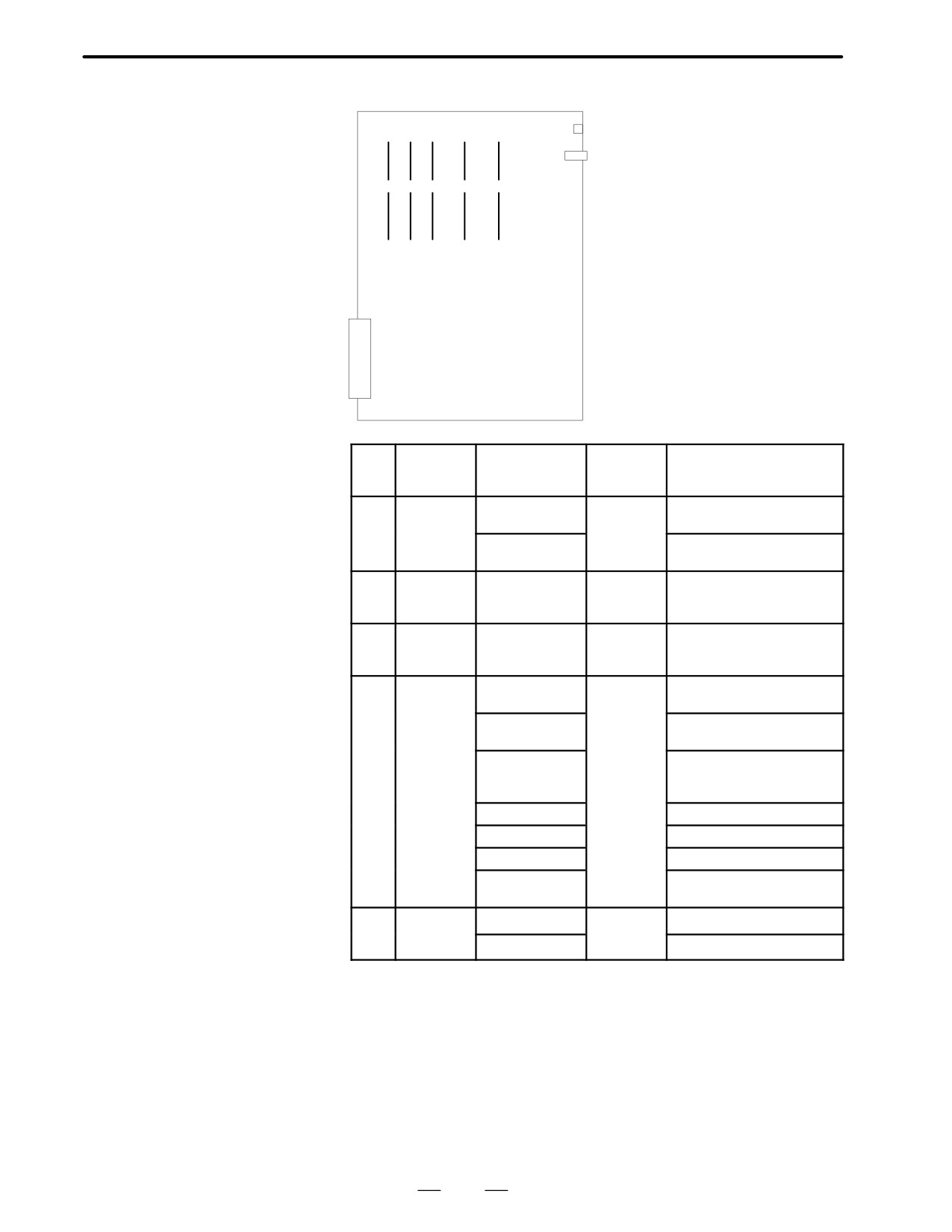
LED display of CAP-II function
j: OFF, J: ON, Ll: Blink, z: Don’t care
No.
LED display
NC statue
1
STATUS JJJJ
Startup status immediately after power is turned on
ALARM jjj
2
STATUS zzjJ
Waiting for each procesor in the system to set its ID
ALARM jjj
3
STATUS zzJj
Waiting for each processor in the system to complete
ALARM jjj
startup
4
STATUS zzjj
The CAP II function startup has been completed and
ALARM jjj
the system is now in normal operation
⋅
LED display when an error occurs
j: OFF, J: ON, Ll: Blink, z: Don’t care
No.
LED display
NC statue
1
STATUS zzLL
NMI from another board (STATUS LEDs 3 and 4 are
ALARM jjj
flashing simultaneously). Check other boards’ LED
display.
2
STATUS zzjL
A CAP II sub-memory parity error occurred. Initialize
ALARM jjj
the sub-memory.
3
STATUS zzLj
A bus error occurred (incorrect memory access).
ALARM jjj
Replace the option 3 board.
4
STATUS zzLl
A ROM parity error occurred (STATUS LEDs 3 and 4
ALARM jjj
are flashing alternately). Replace the CAP II ROM
module.
⋅
Alarm LED display j:OFF, J:ON
LED display
Description
Cause and required action
ALARM jjJ
An I/O link error occurred.
Check the link devices and
cables.
ALARM jJj
A parity error occurred in the
The SRAM module for CAP-II
SRAM for CAP-II
may be out of order
ALARM jJJ
A parity error occurred in the
The DRAM module for PMC
DRAM for PMC
may have failed.
ALARM Jjj
A parity error occurred in the
The DRAM module for CAP-II
DRAM for CAP-II
may have failed
ALARM JjJ
A parity error occurred in the
The DRAM module for PMC
DRAM for PMC
may have failed
ALARM JJj
The CPU for PMC is not started
Check whether the main board
has been activated normally
ALARM JJJ
The operation of the PMC
The PMC module may have
module is abnormal
failed
149
2. HARDWARE
B-62445E/03
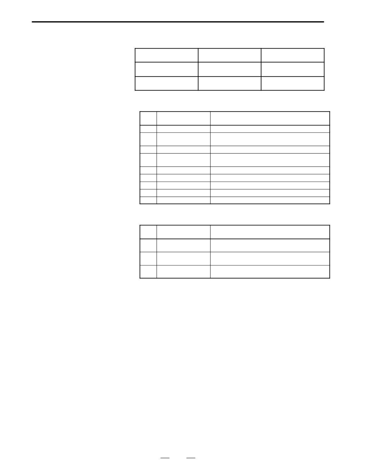
D Location of modules
Connector Connector
LED
name
number Use
IOLINK JD1A2
FANUC I/O LINK
(1)
(2)
(3)
(4)
(5)
JNA
F-BUS
Back
plane
connector
No.
Name
Specifications
Function
Display of system
configuration screen
(1)
ROM
A20B-2900-0290
CAP-II
SYSTEM ROM MODULE
module for
system
:1MB
CAP
A20B-2900-0291
SYSTEM ROM MODULE
:768KB
(2)
ROM
A20B-2901-0390
CPU for
No. display
module for
CAP-II
CAP
(3)
ROM
A20B-2901-0413
DRAM+
SRAM MODULE :512KB
module for
SRAM for
DRAM MODULE :512KB
CAP
CAP-II
(4)
DRAM
A20B-2902-0191
DRAM for
ADDITIONAL DRAM(MGR)
module for
PMC
DRAM(APPLICATION) :2MB
PMC
A20B-2902-0192
ADDITIONAL DRAM(MGR)
DRAM(APPLICATION) :1MB
A20B-2902-0193
ADDITIONAL DRAM(MGR)
DRAM(APPLICATION)
:512KB
A20B-2902-0194
ADDITIONAL DRAM(MGR)
A20B-2902-0196
DRAM(APPLICATION) :2MB
A20B-2902-0197
DRAM(APPLICATION) :1MB
A20B-2902-0198
DRAM(APPLICATION)
:512KB
(5)
PMC
A20B-2901-0960
PMC MODULE:PMP2
module
module
A20B-2901-0961
PMC MODULE:PMP2
150
2. HARDWARE
B-62445E/03
2.5.6
Loader Control boad
Name
Code
Function
Loader control board
A16B-2202-0560
Loader control function
for MAIN-A
Loader control board
A16B-2202-0880
Loader control function
for MAIN-B
⋅
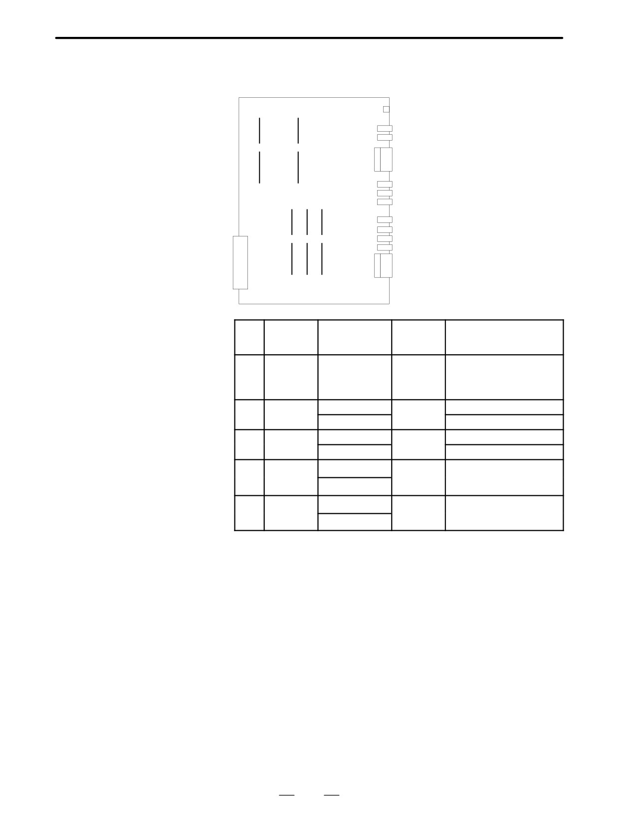
LED display transition when the power is turned on
j: OFF, J: ON
No.
LED display
Description
1
STATUS jjjj
The power is off
2
STATUS JJJJ
The power has just been turned on, or the CPU is not
operating
3
STATUS jJJJ
RAM is initialized
4
STATUS JjJJ
The software ID has been set. The keys are initialized.
All data is cleared.
5
STATUS jjJJ
Software initialization is being awaited (wait state 1)
6
STATUS JJjJ
Software initialization is being awaited (wait state 2)
7
STATUS jJjJ
The position coder is initialized
8
STATUS jJJj
Digital servo initialization is being awaited
9
STATUS Jjjj
Initialization has been completed (steady state)
⋅
LED display upon occurrence of an error
j:OFF, J:ON
No.
LED display
Description
1
STATUS jJjj
Parity alarm in loader control
ALARM Jjj
2
STATUS jJjj
Servo alarm in loader control
ALARM jjJ
3
STATUS jJjj
Alarm other than parity or servo alarm
ALARM jjj
151
2. HARDWARE
B-62445E/03
D Location of modules
D Incase of
A16B-2202-0560
Connector Connector
LED
name
number
Use
BRAKE CNBK Brake output
ESP
CNPW Emergency stop
(1)
(2)
IO-1
CNWF DI/DO for workpiece feeder
TP
CNTP DI/DO for teach pendant
IOLINK JD1A
FANUC I/O LINK
A-OUT JA8
Servo waveform check output
APCBAT JA4
APC battery
AMP1
JV1
Servo amplifier for first axis
AMP2
JV2
Servo amplifier for second axis
JNA
(5)
(3)
(4)
AMP3
JV3
Servo amplfier for third axis
AMP4
JV4
Servo amplifier for fourth axis
F-BUS
Back
IO-2
CRM1
DI/DO for loader main body
plane
JF
CRF1
Pulse coder for first to fourth
connector
axes
No.
Name
Specifications
Function
Display of system
configuration screen
(1)
FROM
A20B-2902-0082
ROM for
FLASH ROM MODULE:2MB
module
macro on
loader con-
trol side
(2)
DRAM
A20B-2901-0941
Loader sys-
DRAM:4MB
module
tem RAM
A20B-2901-0942
DRAM:2MB
(3)
PMC
A20B-2900-0142
PMC control
PMC MODULE: BSI+SLC
module
A20B-2900-0143
PMC MODULE: BSI
(4)
Servo
A20B-2902-0060
Servo
SERVO 3/4 AXIS
module
control 3rd
A20B-2902-0061
or 4th axis
(5)
Servo
A20B-2902-0060
Servo
SERVO 1/2 AXIS
module
control 1st
A20B-2902-0061
or 2nd axis
152
2. HARDWARE
B-62445E/03
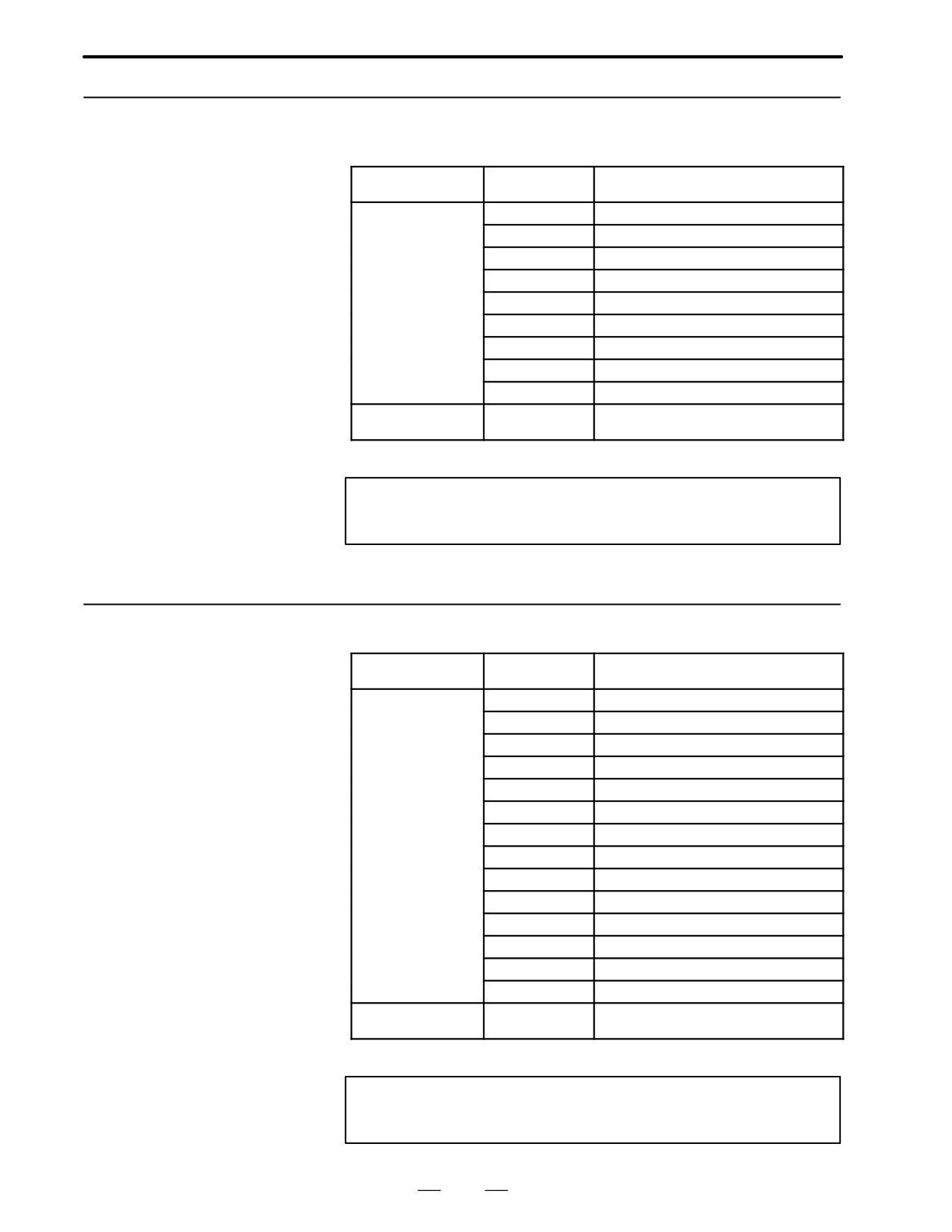
D Location of modules
A16B-2202-0880
Connector
Connector
LED
name
number
Use
BRAKE CNBK Brake output
ESP
CNPW Emergency stop
(1)
(2)
IO-1
CNWF DI/DO for workpiece feeder
TP
CNTP
DI/DO for teach pendant
IOLINK JD1A
FANUC I/O LINK
A-OUT JA8
Servo waveform check output
AMP1
JS1A
Servo amplifier for first axis
AMP2
JS2A
Servo amplifier for second axis
(3)
(4)
(5)
AMP3
JS3A
Servo amplifier for third axis
AMP4
JS4A
Servo amplifier for fourth axis
IO- 2
CRM1
DI/ DO for loader main body
AMP1
No.
Name
Specifications
Function
Display of system
configuration screen
(1)
FROM
A20B-2902-0082
ROM for
FLASH ROM MODULE:2MB
module
macro of
loader side
(2)
DRAM
A20B-2901-0941
Loader sys-
DRAM:4MB
module
tem RAM
A20B-2901-0942
DRAM:2MB
(3)
PMC
A20B-2900-0142
PMC control
PMC MODULE: BSI+SLC
module
A20B-2900-0143
PMC MODULE: BSI
(4)
Servo
A20B-2902-0060
Servo
SERVO 3/4 AXIS
module
control 3rd
A20B-2902-0061
or 4th axis
(5)
Servo
A20B-2902-0060
Servo
SERVO 1/2 AXIS
module
control 1st
A20B-2902-0061
or 2nd axis
153
2. HARDWARE
B-62445E/03
2.5.7
I/O Card
(Sink Type Output)
Name
Code
Function
I/O card
A16B-2200-0950
DI : 104 DO : 80 With high-speed skip
(sink type output)
A16B-2200-0951
DI : 104 DO : 72 With high-speed skip
A16B-2200-0952
DI : 80 DO : 56 With high-speed skip
A16B-2200-0953
DI : 40 DO : 40 With high-speed skip
A16B-2200-0954
High-speed skip only
A16B-2200-0955
DI : 104 DO : 80 Without high-speed skip
A16B-2200-0956
DI : 104 DO : 72 Without high-speed skip
A16B-2200-0957
DI : 80 DO : 56 Without high-speed skip
A16B-2200-0958
DI : 40 DO : 40 Without high-speed skip
I/O card add-on
A20B-9001-0480
Use with A16B-2200-0950 or
board
A16B-2200-0955 listed above
Note
This printed circuit board has no LED display.
2.5.8
I/O Card
Name
Code
Function
(Source Type Output)
I/O card
A16B-2200-0981
DI : 104 DO : 72 With high-speed skip
(Source type output)
A16B-2200-0982
DI : 80 DO : 56 With high-speed skip
A16B-2200-0983
DI : 40 DO : 40 With high-speed skip
A16B-2200-0986
DI : 104 DO : 72 Without high-speed skip
A16B-2200-0987
DI : 80 DO : 56 Without high-speed skip
A16B-2200-0988
DI : 40 DO : 40 Without high-speed skip
A16B-2202-0720
DI : 104 DO : 80 With high-speed skip
A16B-2202-0721
DI : 104 DO : 72 With high-speed skip
A16B-2202-0722
DI : 80 DO : 56 With high-speed skip
A16B-2202-0723
DI : 40 DO : 40 With high-speed skip
A16B-2202-0725
DI : 104 DO : 80 Without high-speed skip
A16B-2202-0726
DI : 104 DO : 72 Without high-speed skip
A16B-2202-0727
DI : 80 DO : 56 Without high-speed skip
A16B-2202-0728
DI : 40 DO : 40 Without high-speed skip
I/O card add on board
A20B-8001-0150
DI : 52 DO : 40 To be used together with
the above card (0720) or (0725)
Note
This printed circuit board has no LED display.
154
2. HARDWARE
B-62445E/03
2.5.9
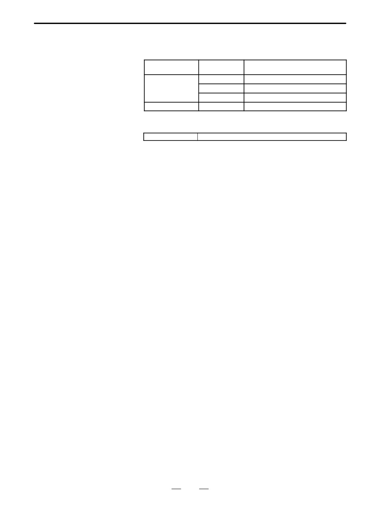
I/O Cards with Power
Supply (Power C)
Name
Code
Function
(Sink Type Output)
I/O card
A16B-2202-0690
DI : 104
DO : 72
(sink type output)
A16B-2202-0691
DI : 80
DO : 56
A16B-2202-0692
DI : 40
DO : 40
Power supply
A20B-1005-0420
To be used with the above I/O card
D LED display
PIL (Green)
Lights when DC input power voltage is applied to CP1A
155
2. HARDWARE
B-62445E/03
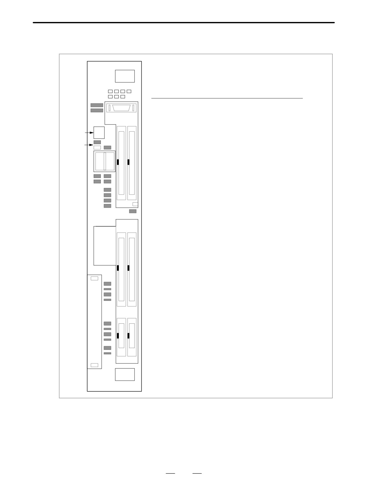
D Positions of connector
etc.
I/O
PSU
Connector
Function
Abbreriation
number
Position 1
1
High-speed skip signal
HDI
JA5B
2
DIGITAL OUTPUT 1
DO-1
C54
11
3
DIGITAL OUTPUT 2
DO-1
C55
12
4
24V Output
DC OUT CP1B
3
2
5
24V Input
DC IN CP1A
5
4
6
Battery
CP8
11
Fuse
12
LED
PIL
7
DIGITAL INPUT 1
DI-1
C50
1
8
DIGITAL INPUT 2
DI-2
C51
3
9
DIGITAL INPUT 3
DI-3
C52
8
7
10
DIGITAL INPUT 4
DI-4
C53
13
Battery case
10
↓
9
156
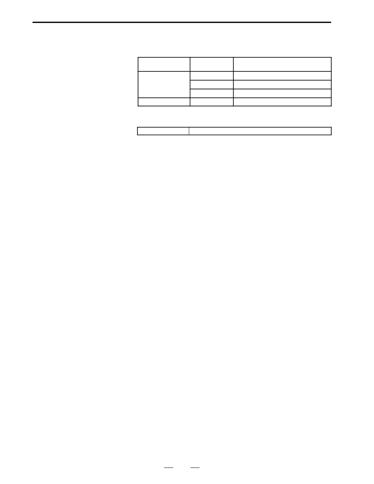
2. HARDWARE
B-62445E/03
2.5.10
I/O Cards with Power
Supply (Power C)
Name
Code
Function
(Source Type Output)
I/O card
A16B-2202-0690
DI : 104 DO : 72
(sink type output)
A16B-2202-0691
DI : 80 DO : 56
A16B-2202-0692
DI : 40 DO : 40
Power supply
A20B-1005-0420
To be used with the above I/O card
D LED display
PIL (Green)
Lights when DC input power voltage is applied to CP1A
157
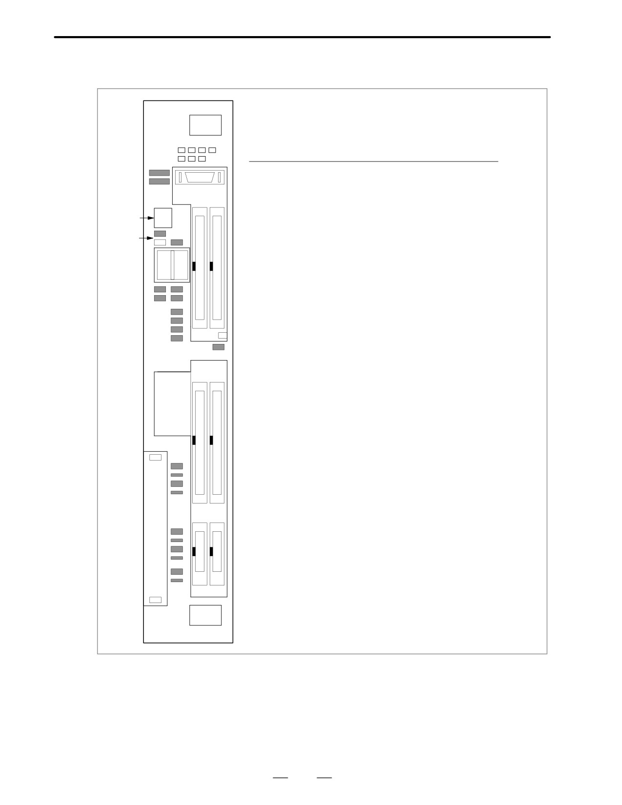
2. HARDWARE
B-62445E/03
D Positions of connector
etc.
I/O
PSU
Connector
Function
Abbreriation
number
Position 1
1
High-speed skip signal
HDI
JA5B
2
DIGITAL OUTPUT 1
DO-1
C74
11
3
DIGITAL OUTPUT 2
DO-1
C75
12
4
24V Output
DC OUT CP1B
3
2
5
24V Input
DC IN CP1A
5
4
6
Battery
CP8
11
Fuse
12
LED
PIL
7
DIGITAL INPUT 1
DI-1
C70
1
8
DIGITAL INPUT 2
DI-2
C71
3
9
DIGITAL INPUT 3
DI-3
C72
8
7
10
DIGITAL INPUT 4
DI-4
C73
13
Battery case
10
↓
9
158
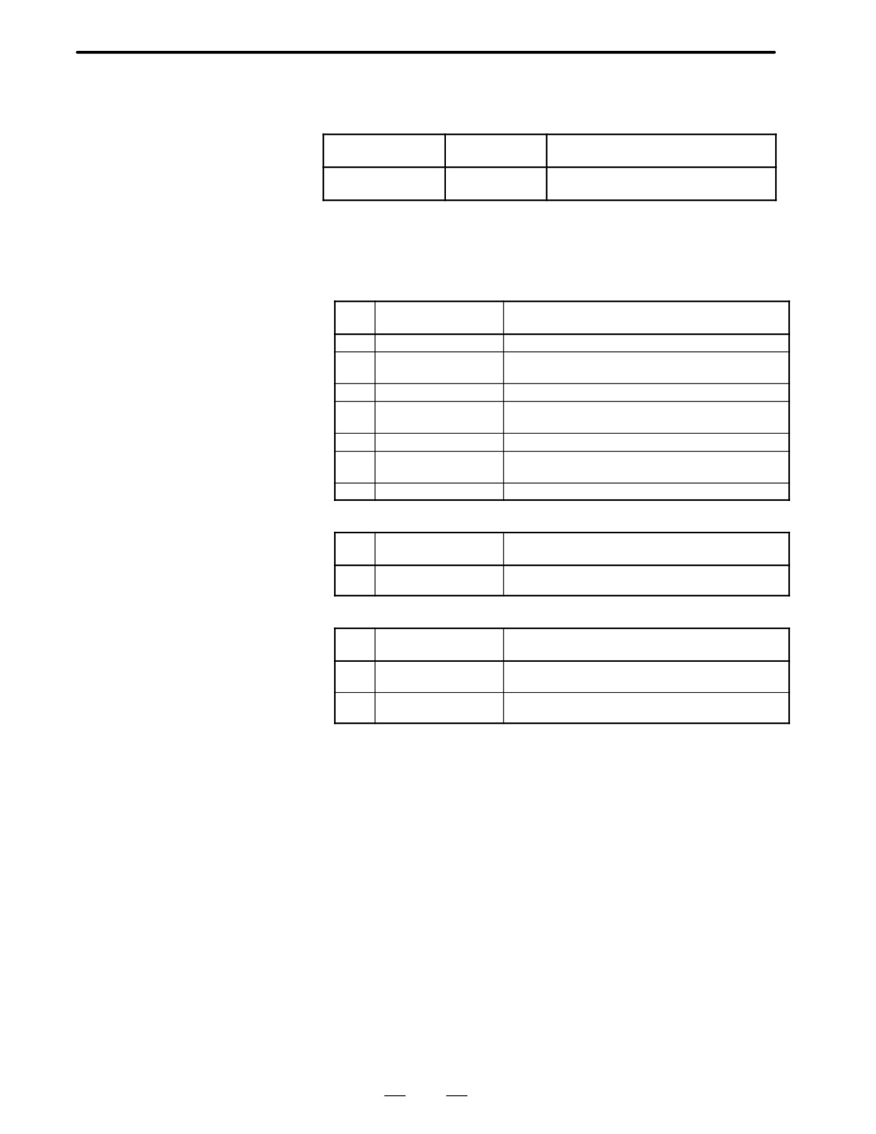
2. HARDWARE
B-62445E/03
2.5.11
Background Graphic
Board
Name
Code
Function
Background graphic
A16B-2202-0852
Background graphic function
board
D LED display
⋅
LED display transition when the power is turned on
The STATUS LEDs are green and the ALARM LEDs are red.
j:OFF, J:ON
No.
LED display
NC statue
1
STATUS jjjj
When power is off
2
STATUS JJJJ
Start up status immediately after power is turned or
CPU is not running
3
STATUS jJJJ
Initializing RAM
4
STATUS JjJJ
Software ID has been set, initialization of keys,
ALL CLR
5
STATUS jjJJ
Waiting for software initialization 1
6
STATUS JJjJ
Waiting for software initialization 2,
Initializing CMOS
7
STATUS Jjjj
Initialization has been completed (steady state).
⋅
LED display when an erro occurs j:OFF, J:ON
No.
LED display
NC statue
1
STATUS jJjj
RAM parity error occurred.
ALARM Jjj
⋅
LED display when system is not started j:OFF, J:ON
No.
LED display
NC statue
1
STATUS JJJJ
SRAM parity error occurred.
ALARM Jjj
2
STATUS JJjj
DRAM parity error occurred.
ALARM Jjj
159
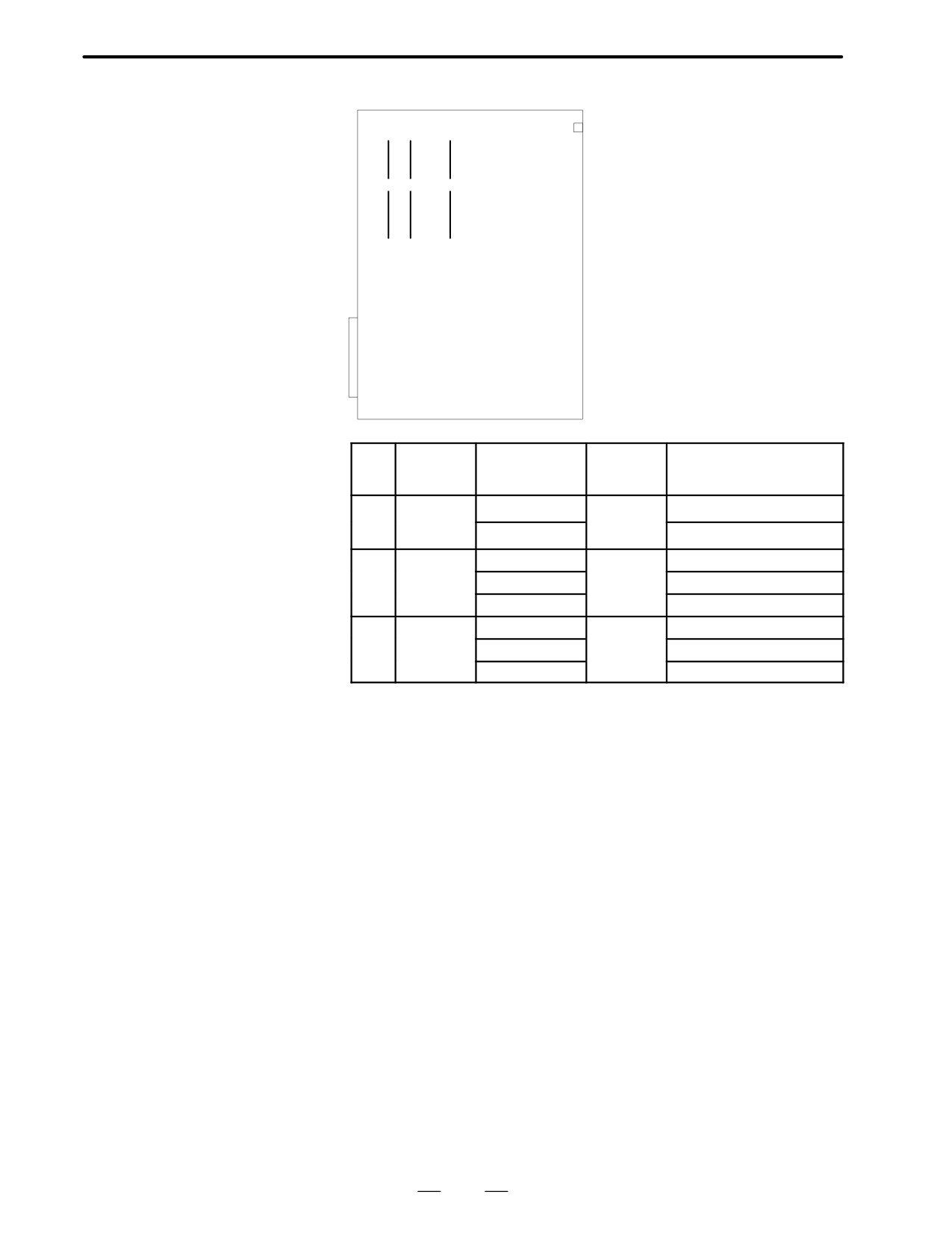
2. HARDWARE
B-62445E/03
D Location of modules
(1)
(2)
(3)
No.
Name
Specifications
Function
Display of system
configuration screen
(1)
FROM
A20B-2902-0081
Background
FLASH ROM MODULE:4MB
module
graphic
A20B-2902-0082
system
FLASH ROM MODULE:2MB
(2)
SRAM
A20B-2902-0350
system
ADDITIONAL SRAM: 256KB
module
RAM
A20B-2902-0351
ADDITIONAL SRAM: 768KB
A20B-2902-0352
ADDITIONAL SRAM: 2.25MB
(3)
DRAM
A20B-2901-0940
system
DRAM:6MB
module
RAM
A20B-2901-0941
DRAM:4MB
A20B-2901-0942
DRAM:2MB
160
2. HARDWARE
B-62445E/03
2.6
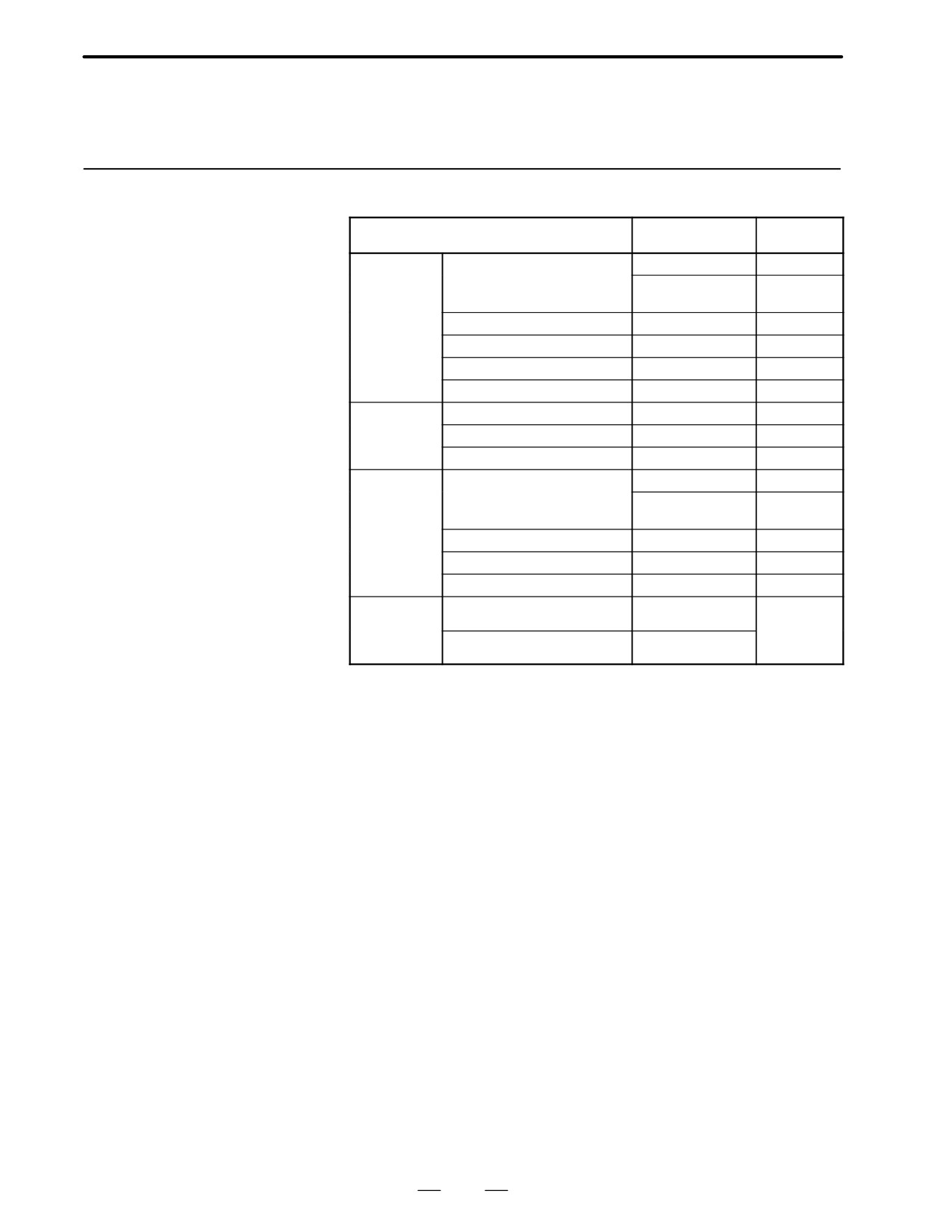
LIST OF THE PCBS
AND UNITS
2.6.1
Control Unit Rack
Name
Drawing No.
Remarks
Series16
2 Slots
A02B-0200-C001
Control unit
A02B-0200-C021
For power
rack (Without
supply C
MMC-IV)
3 Slots
A02B-0200-C005
4 Slots
A02B-0200-C002
6 Slots
A02B-0200-C003
8 Slots
A02B-0200-C004
Series16
4 Slots
A02B-0200-C010
Control unit
6 Slots
A02B-0200-C011
rack (With
MMC-IV)
8 Slots
A02B-0200-C012
Series18
2 Slots
A02B-0129-C001
Control unit
A02B-0129-C021
For power
rack (Without
supply C
MMC-IV)
3 Slots
A02B-0129-C005
4 Slots
A02B-0129-C002
6 Slots
A02B-0129-C003
Series18
4 Slots
A02B-0129-C010
Control unit
rack (With
6 Slots
A02B-0129-C011
MMC-IV)
161
2. HARDWARE
B-62445E/03
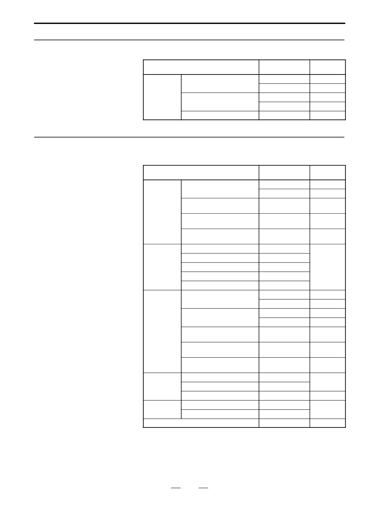
2.6.2
Power Unit
Name
Drawing No.
Remarks
Power unit
AI
A16B-1212-0900
A16B-1212-0901
BI
A16B-1212-0870
A16B-1212-0871
C
A20B-1005-0420
DC24V input
2.6.3
Control Unit P.C.B.
Name
Drawing No.
Remarks
Main CPU
Series 16(MAIN-A, 4-axis
A16B-3200-0010
board
specification)
A16B-3200-0170
Series 16(MAIN-B, 6-axis
A16B-3200-0110
specification)
Series 18(MAIN-B, 4-axis
A16B-3200-0860
specification)
Series 18(MAIN-B, 6-axis
A16B-3200-0160
specification)
Option 1 board
Graphic+remote buffer
A16B-2200-0918
Servo
waveform
Graphic+DNC1
A16B-2200-0916
cannot be
Remote buffer
A16B-2200-0913
displayed.
DNC1
A16B-2200-0914
Graphic
A16B-2200-0919
Option 2 board
Series 16(MAIN-A, specifica-
A16B-2202-0400
tion,with sub–CPU,4 axes)
A16B-2202-0890
Series 16(MAIN-A, specifica-
A16B-2202-0401
tion,without sub–CPU,4 axes)
A16B-2202-0891
Series 16(MAIN-B, specifica-
A16B-2202-0850
tion, with sub-CPU, 6 axes)
Series 16(MAIN-B, specifica-
A16B-2202-0851
tion, without sub-CPU)
Series 18(MAIN-B, specifica-
A16B-2202-0853
tion, with sub-CPU)
Option 3 board
PMC-RC+CAP-II
A16B-3200-0055
PMC-RC
A16B-3200-0054
CAP-II
A16B-3200-0057
Loader
MAIN-A specification
A16B-2202-0560
control board
MAIN-B specification
A16B-2202-0880
Background drawing board
A16B-2202-0852
162
2. HARDWARE
B-62445E/03
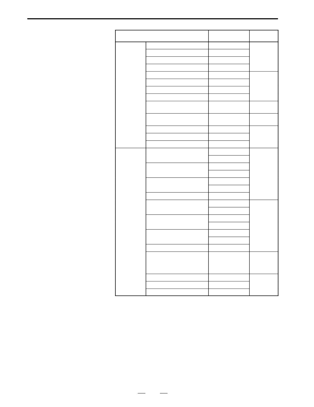
Name
Drawing No.
Remarks
I/O card (sink
A (DI:40 DO:40)
A16B-2200-0958
output type)
B (DI:80 DO:56)
A16B-2200-0957
C (DI:104 DO:72)
A16B-2200-0956
D (DI:104 DO:80)
A16B-2200-0955
E (DI:40 DO:40)
A16B-2200-0953
With high-
speed skip
F (DI:80 DO:56)
A16B-2200-0952
signal input
G (DI:104 DO:72)
A16B-2200-0951
H (DI:104 DO:80)
A16B-2200-0950
Expansioon board
A20B-9001-0480
Used togeth-
er with D or H
High-speed skip signal input
A16B-2200-0954
only
A (DI:40 DO:40)
A16B-2202-0692
Used as
power C
B (DI:80 DO:56)
A16B-2202-0691
C (DI:104 DO:72)
A16B-2202-0690
I/O card
A (DI:40 DO:40)
A16B-2200-0988
(source output
A16B-2202-0728
type)
B (DI:80 DO:56)
A16B-2200-0987
A16B-2202-0727
C (DI:104 DO:72)
A16B-2200-0986
A16B-2202-0726
D (DI:104 DO:80)
A16B-2202-0725
E (DI:40 DO:40)
A16B-2200-0983
With high-
speed skip
A16B-2202-0723
signal input
F (DI:80 DO:56)
A16B-2200-0982
A16B-2202-0722
G (DI:104 DO:72)
A16B-2200-0981
A16B-2202-0721
H (DI:104 DO:80)
A16B-2202-0720
Expansion board
A20B-8001-0150
Used togeth-
er with D
(0725) or H
(0720)
A (DI:40 DO:40)
A16B-2202-0852
Used as
power C
B (DI:80 DO:56)
A16B-2202-0851
C (DI:104 DO:72)
A16B-2202-0850
163
2. HARDWARE
B-62445E/03
Add on board
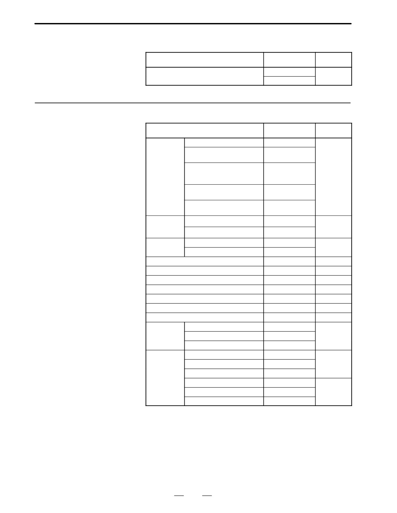
Name
Drawing No.
Remarks
Graphic function board
A20B-8200-0010
For main
CPU board
A20B-8200-0011
2.6.4
Modules
Name
Drawing No.
Remarks
PMC control
For PMC-RE
A20B-2900-0140
module
For loader control (with I/O link
A20B-2900-0142
interface)
For loader control (without I/O
A20B-2900-0143
link interface)
For PMC-RC3
PMC-RB3/RC3 (with I/O link in-
A20B-2901-0960
terface)
PMC-RB3/RC3 (without I/O link
A20B-2901-0961
interface)
High-speed
Analog I/O+high-speed skip DI
A20B-2900-0280
DI, analog I/O
module
High-speed skip DI
A20B-2900-0281
ROM module
1 MB
A20B-2900-0290
768 KB
A20B-2900-0291
Graphic control module
A20B-2900-0311
Graphic CPU module (for CAP-II)
A20B-2900-0350
SRAM module (512 KB)
A20B-2900-0541
14-bit A/D converter module
A20B-2900-0580
SRAM module (2 MB)
A20B-2900-0991
CPU module (for CAP-II)
A20B-2901-0390
DRAM SRAM module
A20B-2901-0413
DRAM
6MB
A20B-2901-0940
module
4MB
A20B-2901-0941
2MB
A20B-2901-0942
Spindle control
Serial+analog
A20B-2901-0980
For main
module
CPU board
Serial
A20B-2901-0981
Analog
A20B-2901-0982
Serial+analog
A20B-2901-0984
For option 2
board
Serial
A20B-2901-0985
Analog
A20B-2901-0986
164
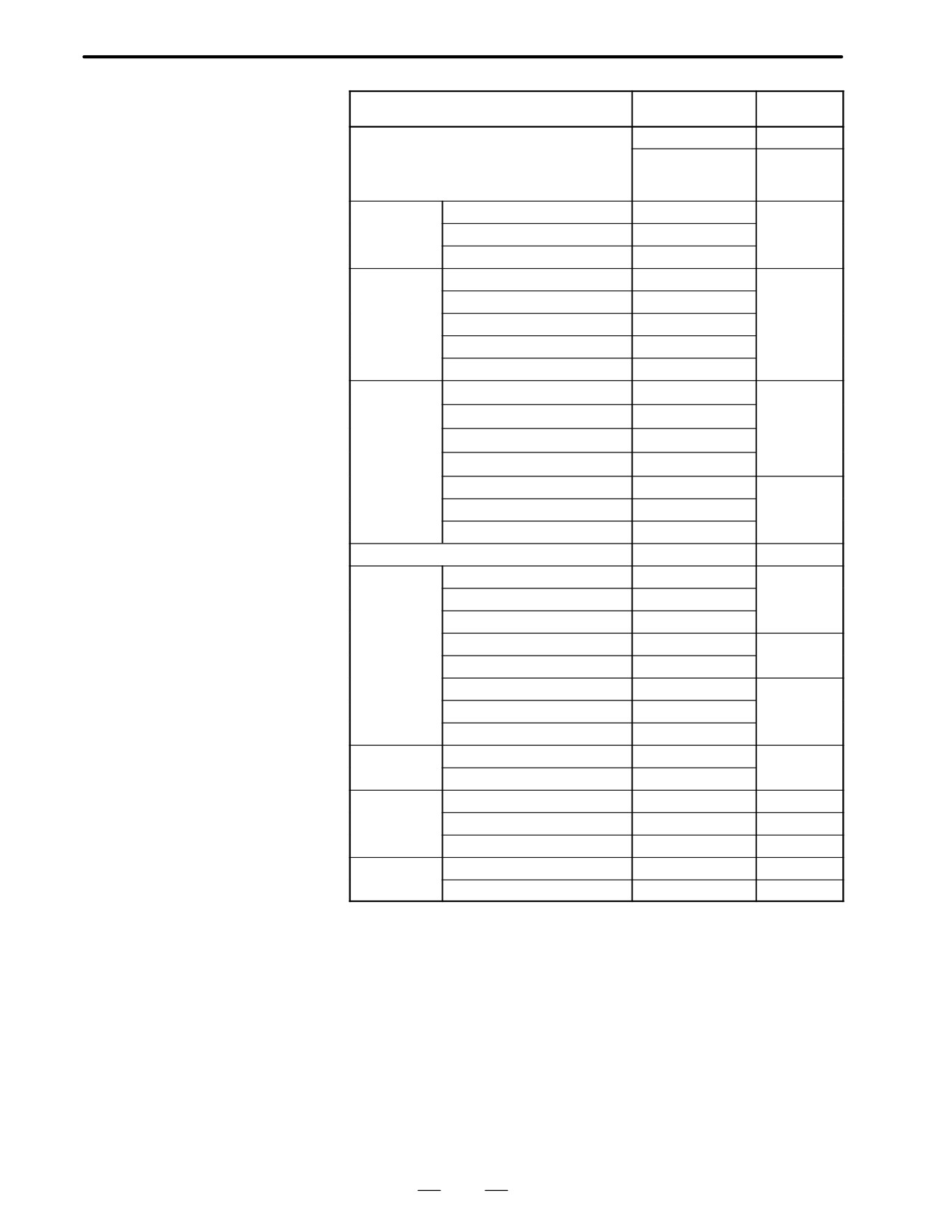
2. HARDWARE
B-62445E/03
Name
Drawing No.
Remarks
Servo control module
A20B-2902-0060
A20B-2902-0061
For learning
control func-
tion
FROM/SRAM
FROM 4MB+SRAM 512KB
A20B-2902-0080
module
FROM 4MB
A20B-2902-0081
FROM 2MB
A20B-2902-0082
FROM/SRAM
FROM 8MB+SRAM 2MB
A20B-2902-0090
module
FROM 8MB
A20B-2902-0091
FROM 6MB
A20B-2902-0092
FROM 8MB+SRAM 512KB
A20B-2902-0093
FROM 6MB+SRAM 512KB
A20B-2902-0094
DRAM module
512KB+2MB
A20B-2902-0191
With man-
agement soft-
512KB+1MB
A20B-2902-0192
ware expan-
512KB+512KB
A20B-2902-0193
sion RAM
(512 KB)
512KB
A20B-2902-0194
(For opton 3)
2MB
A20B-2902-0196
For option 3
1MB
A20B-2902-0197
512KB
A20B-2902-0198
PMC control module (for PMC-RB4/RC4)
A20B-2902-0250
CRT control
For 14″CRT
A20B-2902-0270
When MMC
module
is not pro-
For 9″CRT
A20B-2902-0271
vided
For LCD
A20B-2902-0272
For 14″CRT (MMC-III)
A20B-2902-0273
When MMC
is provided
For LCD (MMC-III, MMC-IV)
A20B-2902-0275
For 9″CRT
A20B-2902-0276
When MMC
is not pro-
For LCD
A20B-2902-0277
vided
For 14″CRT
A20B-2902-0278
FROM/SRAM
FROM 4MB+SRAM 256KB
A20B-2902-0341
module
FROM 2MB+SRAM 256KB
A20B-2902-0343
SRAM module
256KB
A20B-2902-0350
256KB+512KB
A20B-2902-0351
256KB+2MB
A20B-2902-0352
FROM SRAM
FROM 8MB+SRAM 256KB
A20B-2902-0410
module
FROM 6MB+SRAM 256KB
A20B-2902-0411
165
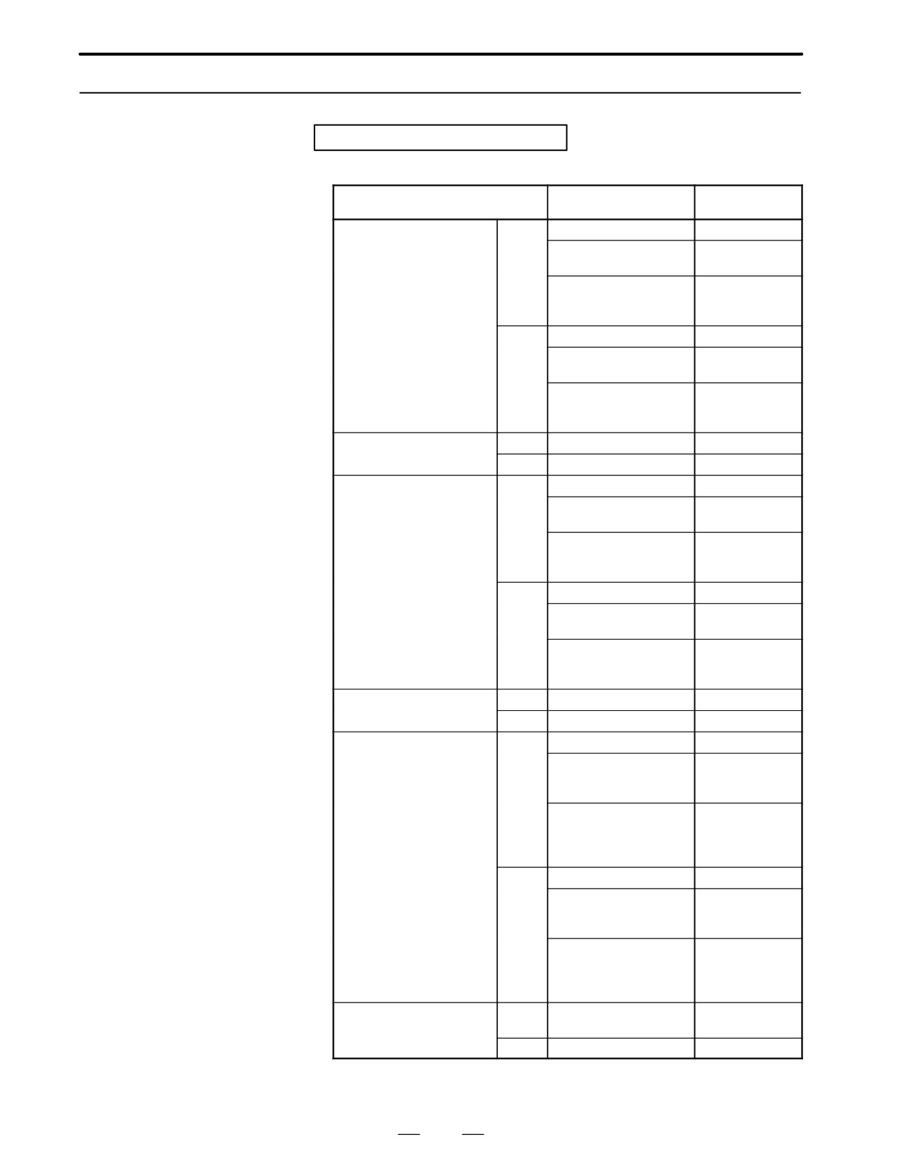
2. HARDWARE
B-62445E/03
2.6.5
CRT/MDI Unit
For system without MMC-IV
Name
Specification
Remarks
9″CRT/MDI
TB
A02B-0120-C041#TA
(small size,monochrome)
A02B-0120-C041#TAR
Conforming to
safety standards
A02B-0120-C041#TAS
Conforming to
safety standards
Symbolic keys
MB
A02B-0120-C041#MA
A02B-0120-C041#MAR
Conforming to
safety standards
A02B-0120-C041#MAS
Conforming to
safety standards
Symbolic keys
9″CRT/MDI
TB
A02B-0120-C042#TA
(small size,color)
MB
A02B-0120-C042#MA
9″CRT/MDI
TB
A02B-0120-C051#TA
(standard,monochrome)
A02B-0120-C051#TAR
Conforming to
safety standards
A02B-0120-C051#TAS
Conforming to
safety standards
Symbolic keys
MB
A02B-0120-C051#MA
A02B-0120-C051#MAR
Conforming to
safety standards
A02B-0120-C051#MAS
Conforming to
safety standards
Symbolic keys
9″CRT/MDI
TB
A02B-0120-C052#TA
(standard,color)
MB
A02B-0120-C052#MA
9″PDP/MDI
TB
A02B-0120-C081#TA
(standard key)
A02B-0200-C101#TBR
Conforming to
safety standards
+24 V input
A02B-0200-C101#TBS
Conforming to
safety standards
+24 V input
Symbolic keys
MB
A02B-0120-C081#MA
A02B-0200-C101#MBR
Conforming to
safety standards
+24 V input
A02B-0200-C101#MBS
Conforming to
safety standards
+24 V input
Symbolic keys
9″ separate-type CRT unit
Mono-
A02B-0120-C111
chrome
Color
A02B-0120-C112
166
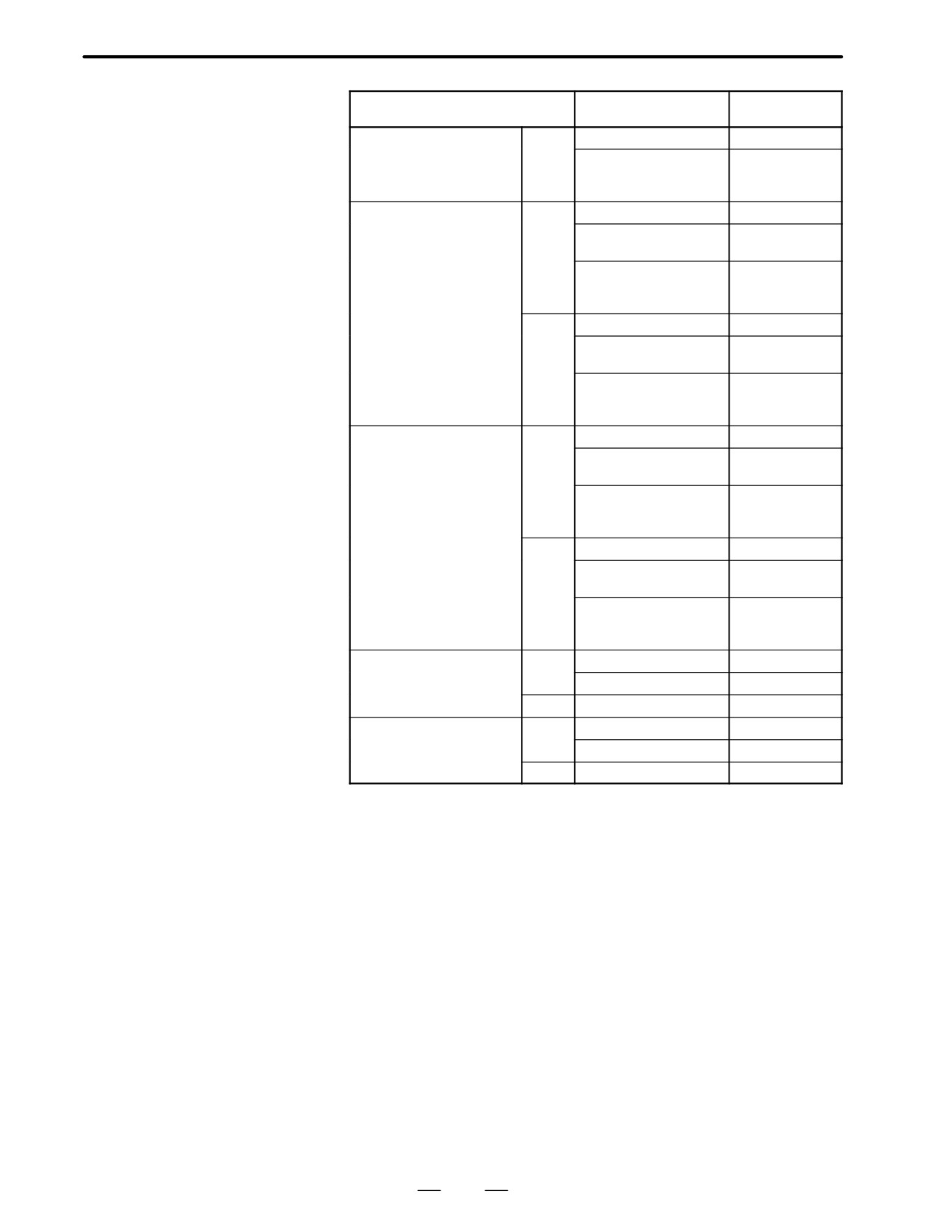
2. HARDWARE
B-62445E/03
Name
Specification
Remarks
9″ separate-type PDP unit
Mono-
A02B-1020-C113
chrome
A02B-0200-C100
Conforming to
safety standards
+24 V input
Separate-type MDI unit
TB
A02B-0120-C121#TA
(small size)
A02B-0120-C121#TAR
Conforming to
safety standards
A02B-0120-C121#TAS
Conforming to
safety standards
Symbolic keys
MB
A02B-0120-C121#MA
A02B-0120-C121#MAR
Conforming to
safety standards
A02B-0120-C121#MAS
Conforming to
safety standards
Symbolic keys
Separate-type MDI unit
TB
A02B-0120-C122#TA
(standard)
A02B-0120-C122#TAR
Conforming to
safety standards
A02B-0120-C122#TAS
Conforming to
safety standards
Symbolic keys
MB
A02B-0120-C122#MA
A02B-0120-C122#MAR
Conforming to
safety standards
A02B-0120-C122#MAS
Conforming to
safety standards
Symbolic keys
14″ CRT/MDI
TB
A02B-0120-C071#TA
(color,landscape type)
A02B-0120-C071#TF
For CAP-II
MB
A02B-0120-C071#MA
14″ CRT/MDI
TB
A02B-0120-C072#TA
(color,portrait type)
A02B-0120-C072#TF
For CAP-II
MB
A02B-0120-C072#MA
167
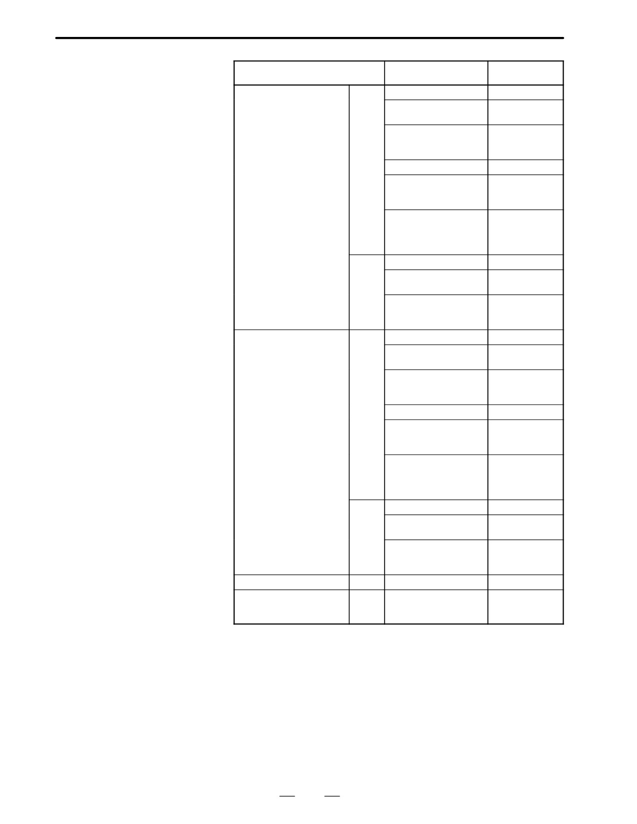
2. HARDWARE
B-62445E/03
Name
Specification
Remarks
9.5″ LCD/MDI
TB
A02B-0200-C061#TB
(color,landscape type)
A02B-0200-C061#TBR
Conforming to
safety standards
A02B-0200-C061#TBS
Conforming to
safety standards
Symbolic keys
A02B-0200-C061#TFB
For CAP-II
A02B-0200-C061#TFBR
For CAP-II
Conforming to
safety standards
A02B-0200-C061#TFBS
For CAP-II
Conforming to
safety standards
Symbolic keys
MB
A02B-0200-C061#MB
A02B-0200-C061#MBR
Conforming to
safety standards
A02B-0200-C061#MBS
Conforming to
safety standards
Symbolic keys
9.5″ LCD/MDI
TB
A02B-0200-C062#TB
(color,portrait type)
A02B-0200-C062#TBR
Conforming to
safety standards
A02B-0200-C062#TBS
Conforming to
safety standards
Symbolic keys
A02B-0200-C062#TFB
For CAP-II
A02B-0200-C062#TFBR
For CAP-II
Conforming to
safety standards
A02B-0200-C062#TFBS
For CAP-II
Conforming to
safety standards
Symbolic keys
MB
A02B-0200-C062#MB
A02B-0200-C062#MBR
Conforming to
safety standards
A02B-0200-C062#MBS
Conforming to
safety standards
Symbolic keys
8.4″ separate-type LCD unit
Color
A02B-0200-C050
7.2″ separate-type LCD unit
Mono-
A02B-0200-C081
chrom
e
168
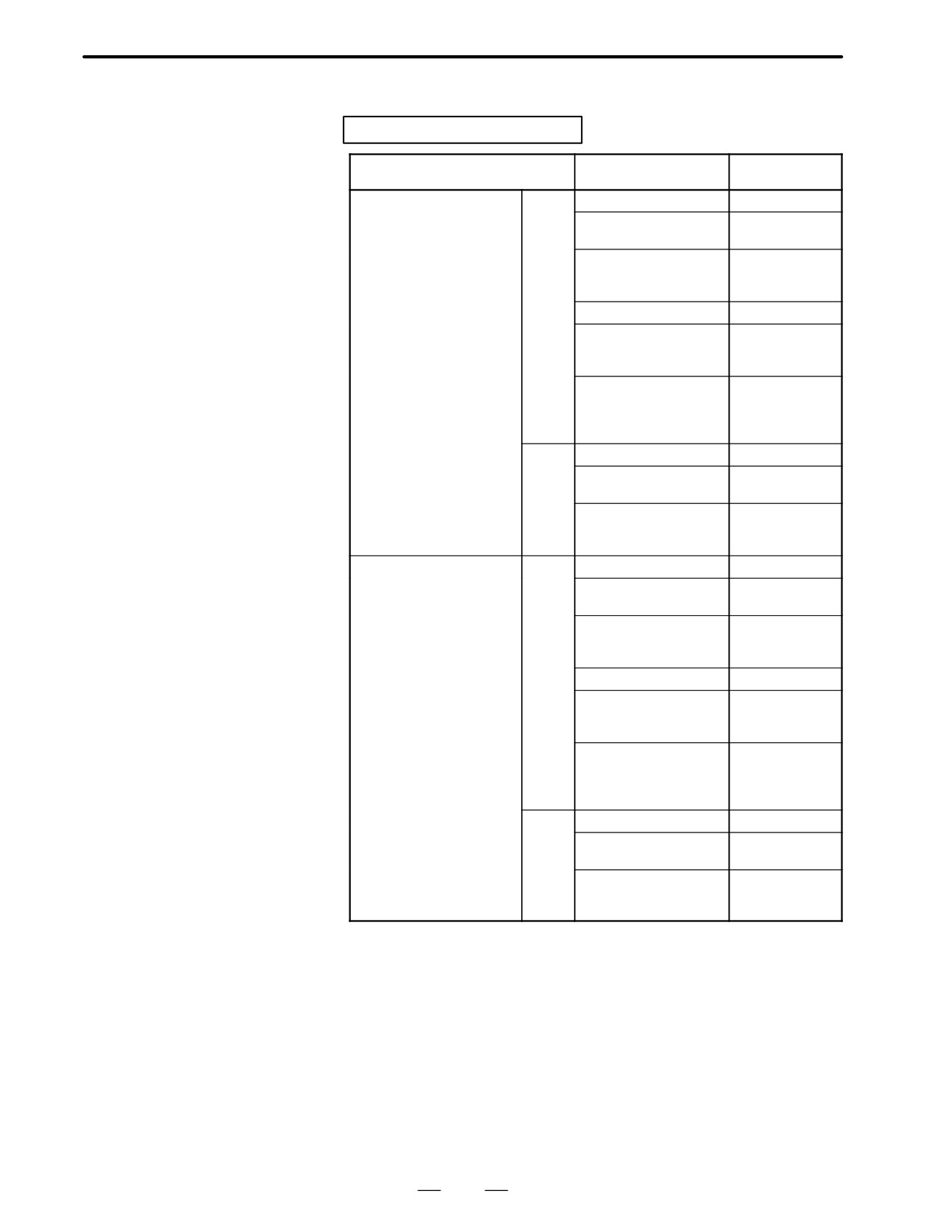
2. HARDWARE
B-62445E/03
For system with MMC-IV
Name
Specification
Remarks
14″ CRT/MDI
TB
A02B-0200-C071#TB
(color,landcape type)
A02B-0200-C071#TBR
Conforming to
safety standards
A02B-0200-C071#TBS
Conforming to
safety standards
Symbolic keys
A02B-0200-C071#TFB
For CAP-II
A02B-0200-C071#TFBR
For CAP-II
Conforming to
safety standards
A02B-0200-C071#TFBS
For CAP-II
Conforming to
safety standards
Symbolic keys
MB
A02B-0200-C071#MB
A02B-0200-C071#MBR
Conforming to
safety standards
A02B-0200-C071#MBS
Conforming to
safety standards
Symbolic keys
14″ CRT/MDI
TB
A02B-0200-C072#TB
(color,portrait type)
A02B-0200-C072#TBR
Conforming to
safety standards
A02B-0200-C072#TBS
Conforming to
safety standards
Symbolic keys
A02B-0200-C072#TFB
For CAP-II
A02B-0200-C072#TFBR
For CAP-II
Conforming to
safety standards
A02B-0200-C072#TFBS
For CAP-II
Conforming to
safety standards
Symbolic keys
MB
A02B-0200-C072#MB
A02B-0200-C072#MBR
Conforming to
safety standards
A02B-0200-C072#MBS
Conforming to
safety standards
Symbolic keys
169
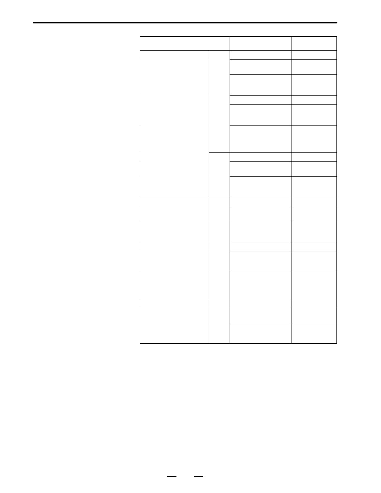
2. HARDWARE
B-62445E/03
Name
Specification
Remarks
9.5″ LCD/MDI
TB
A02B-0200-C065#TB
(color,landcape type)
A02B-0200-C065#TBR
Conforming to
safety standards
A02B-0200-C065#TBS
Conforming to
safety standards
Symbolic keys
A02B-0200-C065#TFB
For CAP-II
A02B-0200-C065#TFBR
For CAP-II
Conforming to
safety standards
A02B-0200-C065#TFBS
For CAP-II
Conforming to
safety standards
Symbolic keys
MB
A02B-0200-C065#MB
A02B-0200-C065#MBR
Conforming to
safety standards
A02B-0200-C065#MBS
Conforming to
safety standards
Symbolic keys
9.5″ LCD/MDI
TB
A02B-0200-C066#TB
(color,portrait type)
A02B-0200-C066#TBR
Conforming to
safety standards
A02B-0200-C066#TBS
Conforming to
safety standards
Symbolic keys
A02B-0200-C066#TFB
For CAP-II
A02B-0200-C066#TFBR
For CAP-II
Conforming to
safety standards
A02B-0200-C066#TFBS
For CAP-II
Conforming to
safety standards
Symbolic keys
MB
A02B-0200-C066#MB
A02B-0200-C066#MBR
Conforming to
safety standards
A02B-0200-C066#MBS
Conforming to
safety standards
Symbolic keys
170
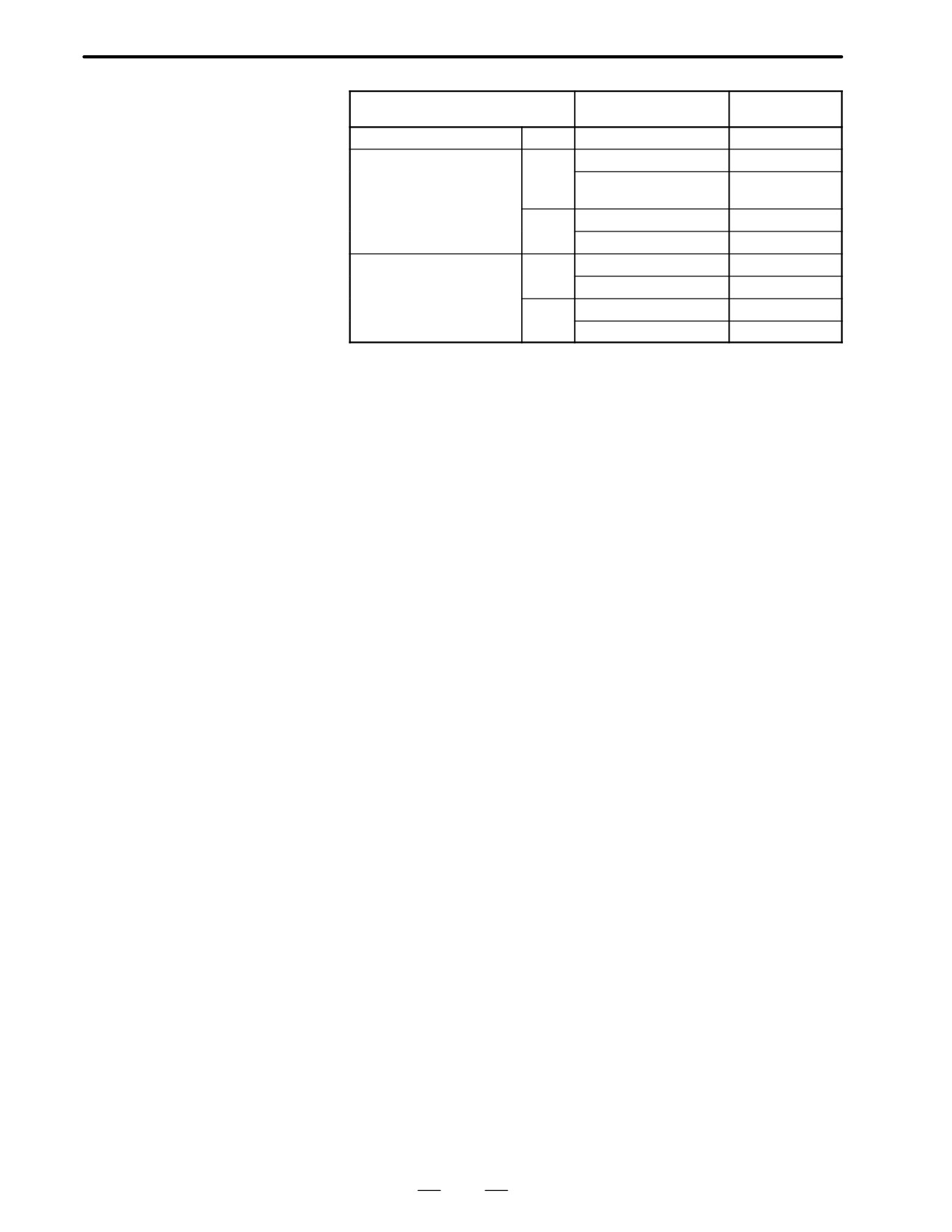
2. HARDWARE
B-62445E/03
Name
Specification
Remarks
8.4″ separate-type LCD unit
Color
A02B-0200-C051
Separate-type MDI unit
TB
A02B-0120-C121#TA
(small size)
A02B-0120-C121#TAR
Conforming to
safety standards
MB
A02B-0120-C121#MA
A02B-0120-C121#MAR
Separate-type MDI unit
TB
A02B-0120-C122#TA
(standard)
A02B-0120-C122#TAR
MB
A02B-0120-C122#MA
A02B-0120-C122#MAR
171
2. HARDWARE
B-62445E/03
2.7
HOW TO REPLACE
THE MODULES
2.7.1
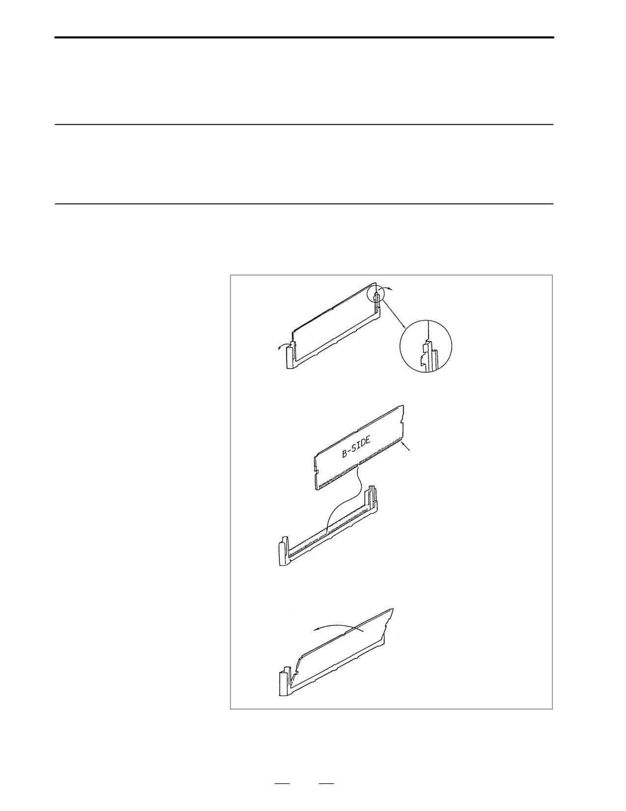
Removing
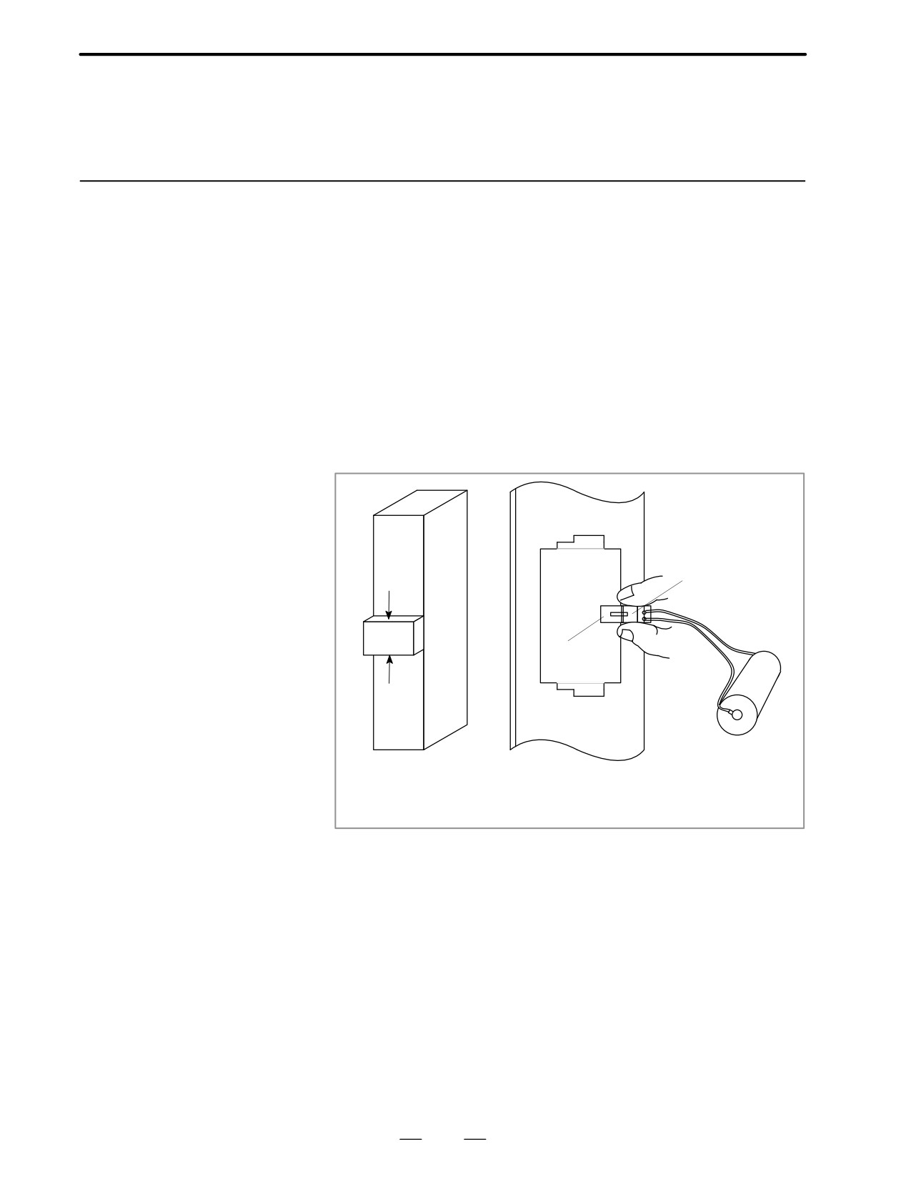
(1) Pull the latches of the module socket outwards. (Fig.(a))
(2) Pull out the module upward. (Fig.(b))
2.7.2
Insertion
(1) Insert the new module board diagonally with B-SIDE outward (Fig.b)
(2) While pushing on the upper edge of the module board, raise it until it
is locked (Fig.(c)).
(a)
No.1 pin
(b)
(c)
172
2. HARDWARE
B-62445E/03
2.8
HOW TO REPLACE
THE BATTERIES
2.8.1
1.
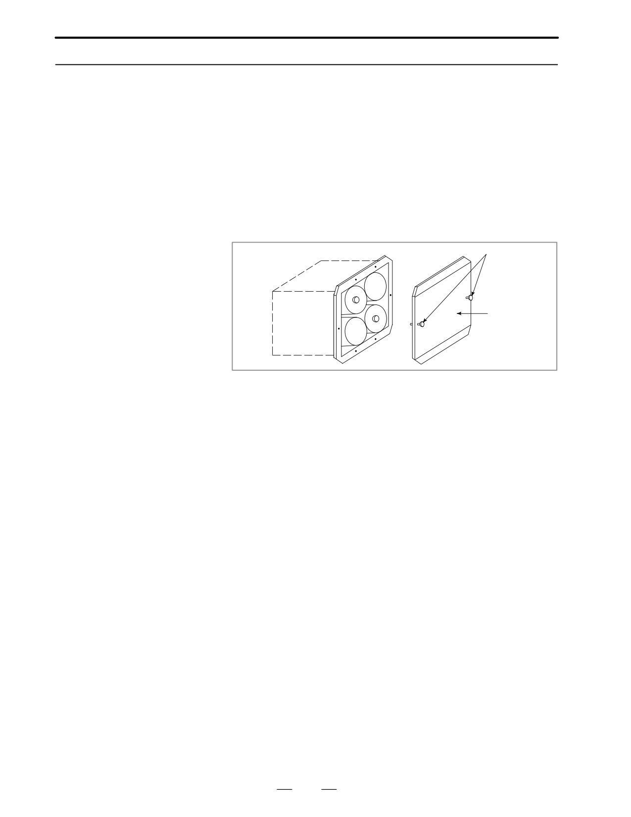
Lithium battery (Order number is *A02B-0200-K102) is required.
Replace the Battery
2. The battery used for memory back up is located on the front of the main
board.
for Memory Back Up
3. Remove the battery cover on the main board by holding the upper and
lower part of the battery cover and pulling it towards you. Then take
off the battery.
4. Remove the connector on the main board towards you.
If you replace the battery while the CNC power is off, you should
replace it within 30 minutes. If it will take more than 30 minutes, you
should replace the battery with power on. Or the CNC memory
contents will be lost.
5. Connect the connector of new battery.
6. Mount a battery and put the battery cover back on.
BATTERY
Power
supply
Connector on
unit
cable
Battery
unit
Connector on
PCB side
Battery
Power supply
unit front panel
Battery Replacement
* FANUC’s order number : A98L-0031-0012
173
2. HARDWARE
B-62445E/03
2.8.2
1.
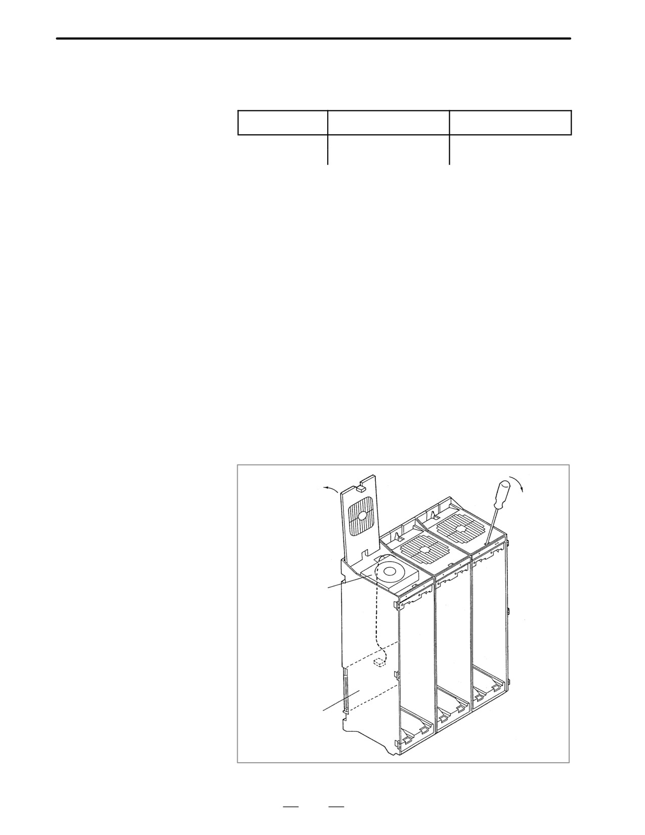
Prepare 4 commercially available dry cell batteries
Replacing Batteries for
2. Turn on CNC power.
If the batteries are replaced with the power off ,absolute position of the
Separate Absolute
machine is lost.
Pulse Coder
3. Loosen the screws of battery case lid and remove the lid.
Consult with the MTB’s manual for where the battery case is installed.
4. Replace the batteries in the case.
Take care to place the batteries facing in the correct direction. (Insert
the batteries as shown in the diagram with 2 facing one way and 2 the
other.)
D Figure of replacing
batteries
Thread
Ç
Ç Lid
Ç
5. Having exchanged the batteries put the lid back on.
6. Turn off the power once, then turn it to on.
7. A battery alarm may be generated, but execute power off and on.
8. Procedure completes.
174
2. HARDWARE
B-62445E/03
2.9
HOW TO REPLACE
Fan ordering information
FAN MOTOR
Ordering code
Number of units required
For 2-slot rack
A90L-0001-0378
For 1-slot rack
For 1-slot rack
A90L-0001-0385#A
For 2-slot rack
1.
Remove the control section printed circuit board underneath the fan to
be replaced.
2.
There is a backplane inside the slot. The fan motor cable is connected
to the backplane. Grasp the left and right side of the cable connector
attached to the backplane and remove it.
3.
Open the upper lid of the control section rack. Insert a philips head
screwdriver into the hole at the center front of the lid. The latch
holding the cover in place can be released by prying with the
screwdriver in the direction shown in (3) of following figure.
4.
Open the lid sufficiently and remove the fan motor. Since the fan itself
is not screwed into the rack, it can be easily removed.
5.
Install the new fan motor. Guide the fan motor cable through the hole
and into the rack.
6.
Close the lid until the latch locks.
7.
Attach the fan motor cable to the connector on the back plane. At this
time,affix the middle portion of the cable to the hooks at the back of
the rack.
8.
Insert the removed control section printed circuit board.
(3)
(4)
Fan motor
Cable
Connector
Back plane
Fig. 2.9 Fan Motor Replacement
175