FANUC Series 16 / 160 / 18 / 180 – Model B. Maintenance Manual - page 5
2. HARDWARE
B-62445E/03
2.4.9
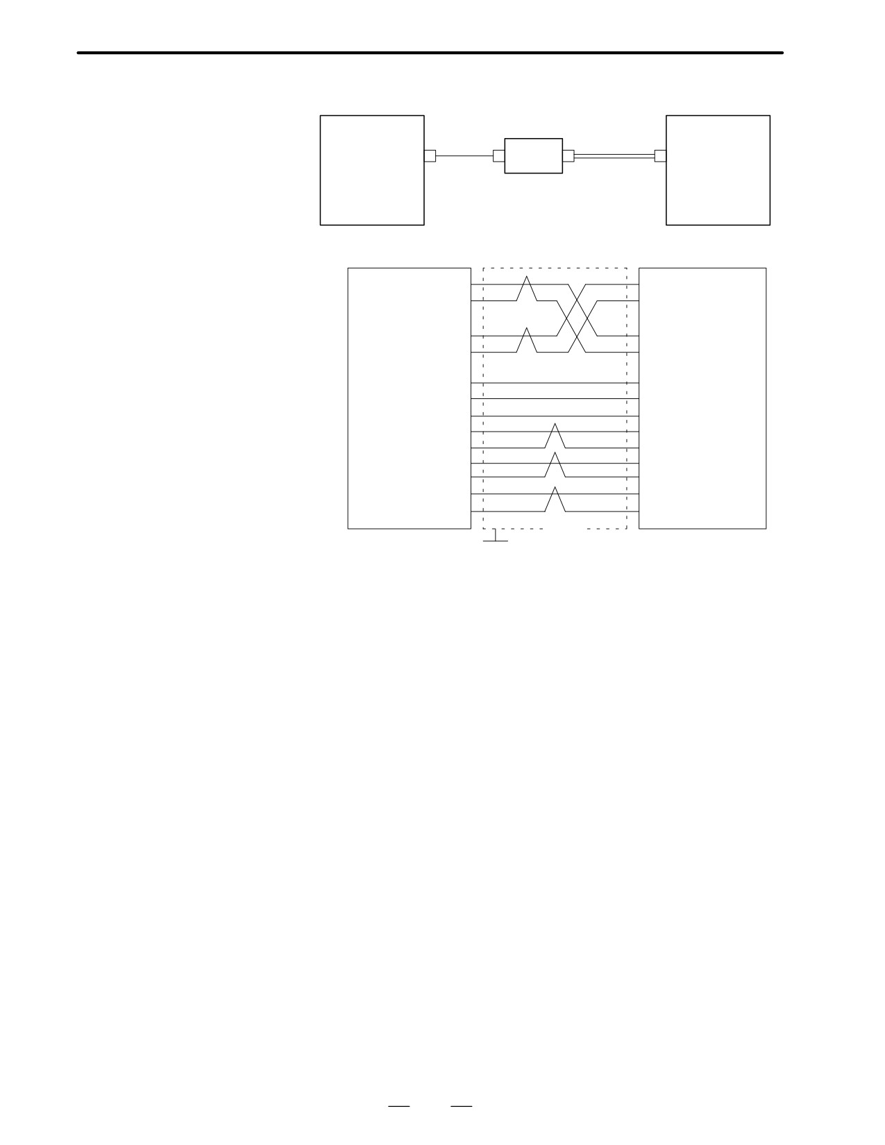
Optical I/O link
Connection to Serial
SPDL-x
Main CPU board
adapter
Serial
(JA7A, B)
Spindle Amplifier
Option 2 board
Optical fiber
spindle
amplifier
x:1, 2
JD1
COP1
CN11A
JD1(Optical I/O link
SPDL-x (JA7A, B)
adapter)
SIN (01)
(02) SIN
*SIN (02)
(01) *SIN
SOUT (03)
(04) SOUT
*SOUT (04)
(03) *SOUT
+5V (09)
(09) +5V
+5V (18)
(18) +5V
+5V (20)
(20) +5V
0V (11)
(11) 0V
0V (12)
(12) 0V
0V (13)
(13) 0V
0V (14)
(14) 0V
0V (15)
(15) 0V
0V (16)
(16) 0V
Shield
Connector:Half-pitch
Connector:Half-pitch
G
20-pin
20-pins
Recommended cable:A66L-0001-0284#10P(#28AWG
10pairs)
114
2. HARDWARE
B-62445E/03
2.4.10
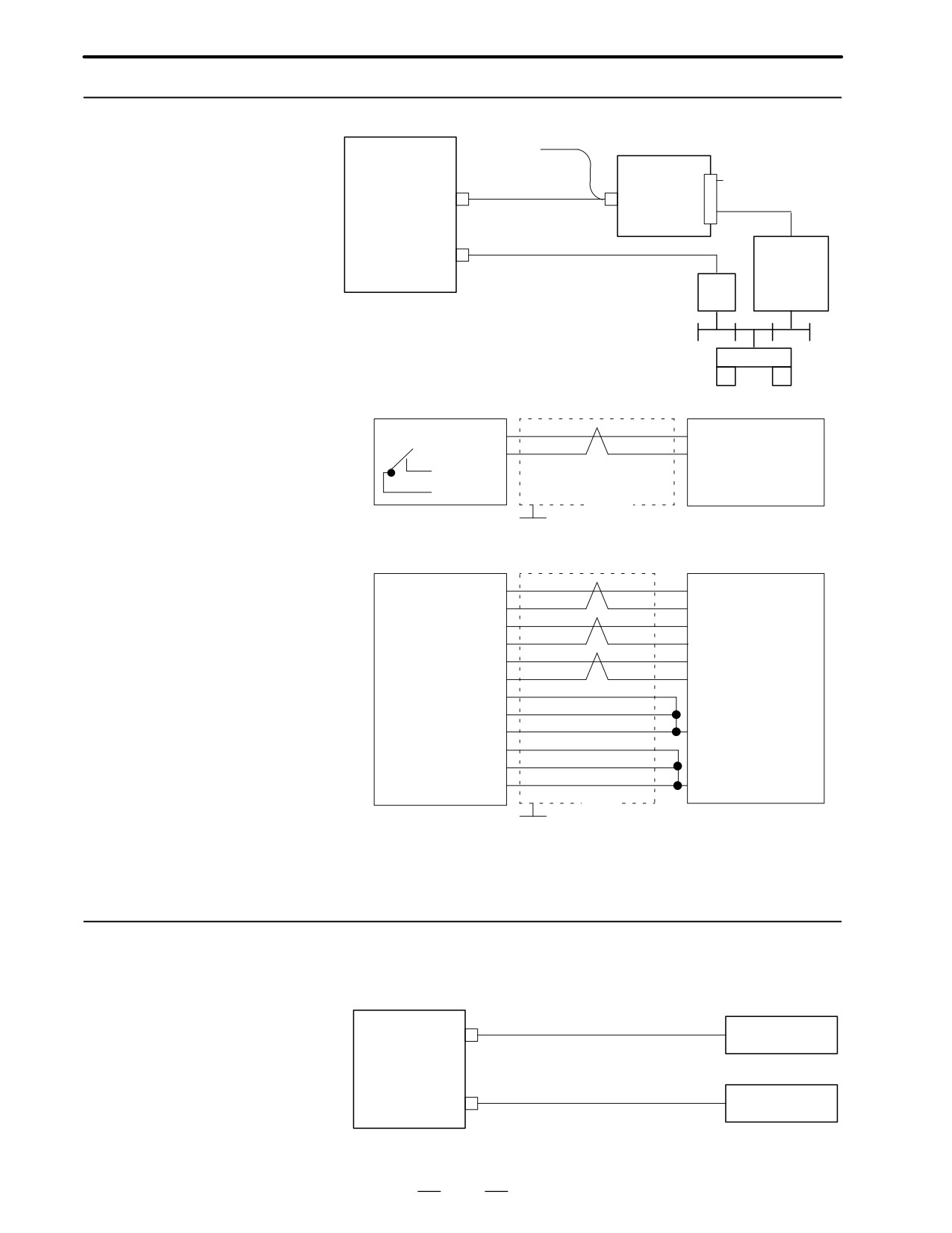
Connection to Analog
Main CPU board
Control signal
Option 2 board
Analog
Spindle Amplifier
spindle
AC200V
A-OUTx (JA8A, B)
amplifier
SPDL-x (JA7A, B)
Spindle
x:1, 2
Position coder
motor
PC
Spindle
A-OUTx(JA8A, B)
Analog spindle amplifier
SVC (07)
0V (05)
ENB1 (08)
ENB2 (09)
Shield
Connector : Half-pitch
Connector : MR20-pin
G
20-pins
SPDL-x(JA7A, B)
Position coder
SC (01)
(B) SC
*SC (02)
(P)
*SC
PA (05)
(A) PA
*PA (06)
(N)
*PA
PB (07)
(C) PB
*PB (08)
(R)
*PB
+5V (09)
+5V (18)
+5V (20)
(H)
+5V
0V (12)
0V (14)
0V (16)
(K)
0V
Shield
Connector : Half-pitch
Connector : CANON
G
20-pins
Recommended cable : A66L-0001-0286(#20AWG
3 pairs, Max.20m)
2.4.11
Remote Buffer Interface
D Connection
R232-1(JD5C)
(Channel 3)
Host computer
Option 1 board
R422-1(JD6A)
Host computer
115
2. HARDWARE
B-62445E/03
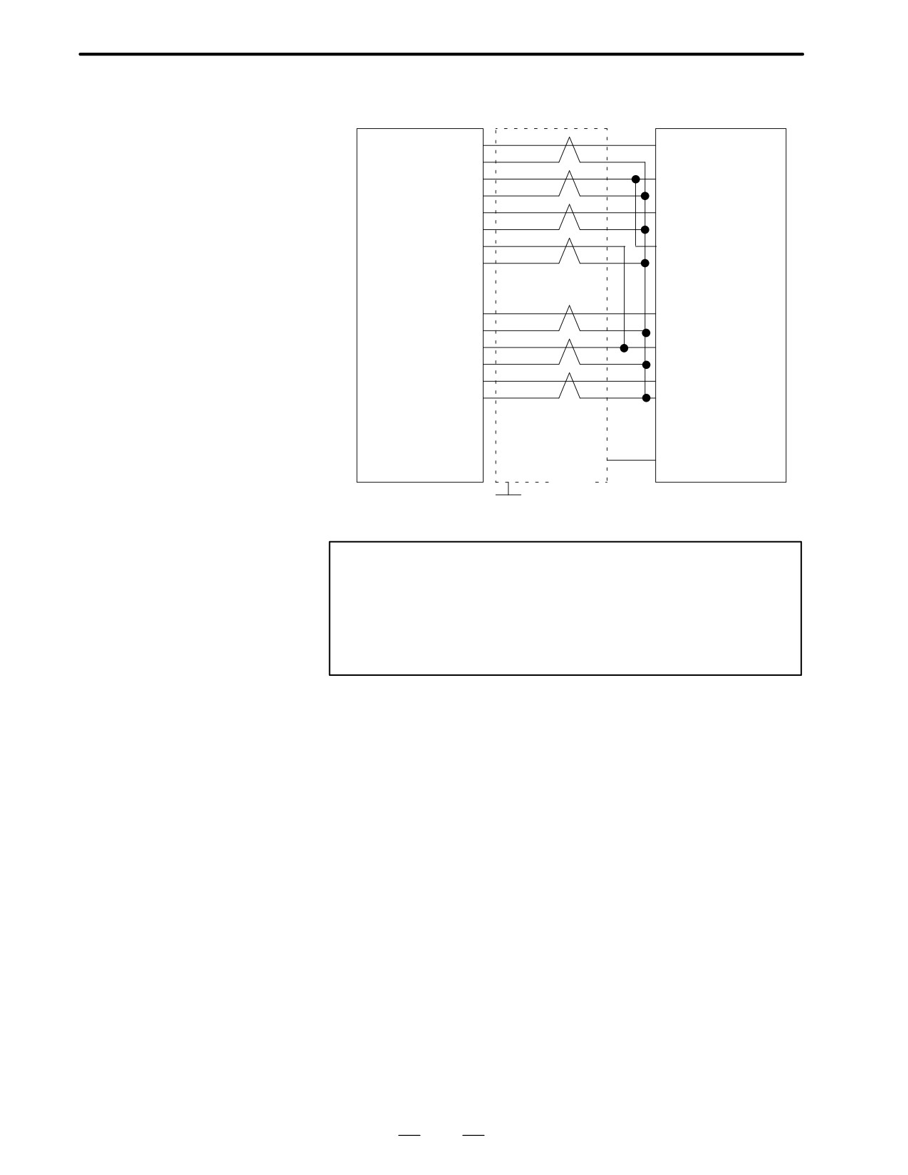
D Example of cable
connection
R232-3(JD5C)
Host computer
RD (01)
(02) SD
0V (02)
DR (03)
(20) ER
0V (04)
CS (05)
(04) RS
0V (06)
CD (07)
(08) CD
0V (08)
(09)
+24V (10)
SD (11)
(03) RD
0V (12)
ER (13)
(06) DR
0V (14)
RS (15)
(05) CS
0V (16)
(07) SG
(17)
(18)
+24V (19)
(25) +24V
(20)
(01) FG
Shield
Connector:
Half-pitch
Connector: D-SUB 25-pin
G
20-pins (PCR)
Notes
1
Connect RS when CS is not used.
2
Connect as follows when protocol A or extended protocol A
is used:
a) Connect to ER when DR is not used.
b) Always connect CD to ER
116
2. HARDWARE
B-62445E/03
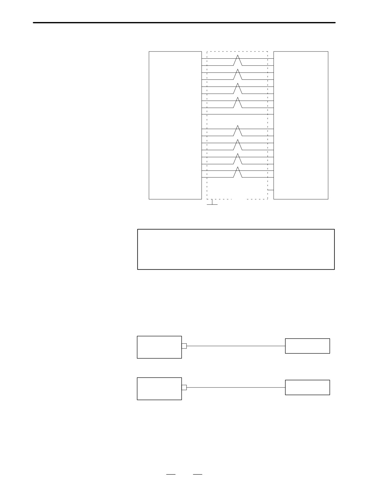
D Example of RS-422
R422-1(JD6A)
Host computer
cable
RD (01)
(04) RD
*RD (02)
(22) *RD
RT (03)
(17) TT
*RT (04)
(35) *TT
CS (05)
(07) RS
*CS (06)
(25) *RS
DM (07)
(11) TR
Note) *DM (09)
(29) *TR
0V (08)
(19) SG
(+24V) (10)
SD (11)
(06) RD
*SD (12)
(24) *RD
TT (13)
(08) RT
*TT (14)
(26) *RT
RS (15)
(09) CS
*RS (16)
(27) *CS
TR (17)
(12) TR
*TR (18)
(30) *TR
(+24V) (19)
(20)
(01) FG
Shield
Connector : Half-pitch 20
pins (PCR)
G
Connector : D-SUB25 Pin
Note
Be sure to use the twisted pair cable. Note that pin
arrangement of *DM signal on NC side is not regular to
escape from damage due to wrong connection.
2.4.12
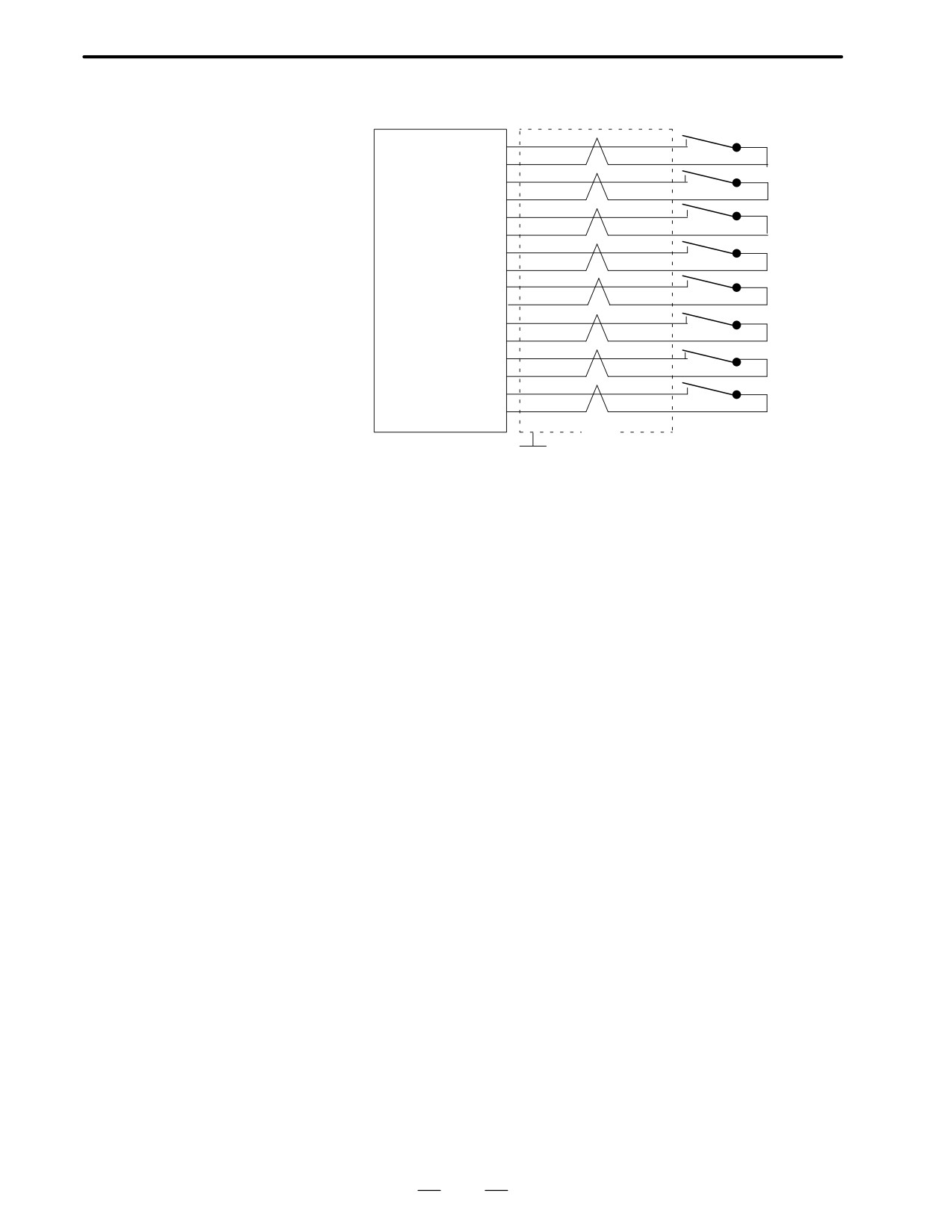
High-speed DI Signal
Interface
D Connection diagram
HDI (JA5)
Option 2A/B board
Touch sensor
HDI (JA5)
Built-in I/O card
Touch sensor
117
2. HARDWARE
B-62445E/03
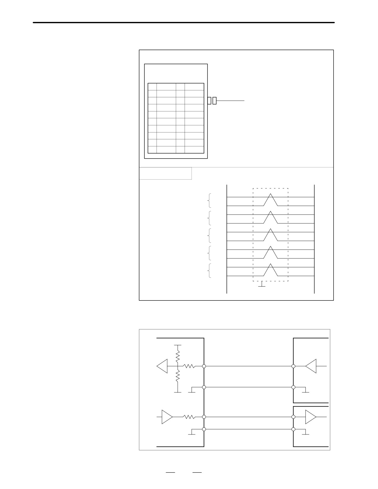
D Connection details
HDI (JA5)
HDI0 (01)
0V (02)
HDI1 (11)
0V (12)
HDI2 (03)
0V (04)
HDI3 (13)
0V (14)
HDI4 (05)
0V (06)
0V (16)
HDI6 (07)
0V (08)
HDI7 (17)
0V (18)
Shield
Connector: Half-pitch
20-pin (PCR)
G
Parameter 6200 and 6202 decide which signals are used for the high speed
skip signal.
118
2. HARDWARE
B-62445E/03
2.4.13
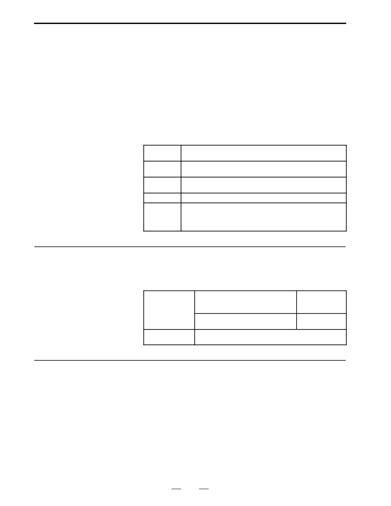
Analog signal interface
CNC OPTION 2
JA6
(PCR-EV20MDT)
1
AIN0
11
AIN1
2
0V
12
0V
3
AIN2
13
AIN3
4
0V
14
0V
5
AOUT
15
6
0V
16
0V
7
17
8
18
9
19
10
20
Cable connection
1
AIN0
Analog input CH0
2
0V
11
AIN1
Analog input CH1
12
0V
3
AIN2
Analog input CH2
4
0V
13
AIN3
Analog input CH3
14
0V
5
AOUT
Analog output
0V
Shield
G
D Receiver circuit
CNC
5V
18kΩ
36kΩ
AIN0X3
Input voltage range -10V to +10V
36kΩ
Input current range -0.5mA to +0.5mA
0V
0V
0V
1000kΩ
AOUT
Output voltage -10V to +10V
0V
0V
119
2. HARDWARE
B-62445E/03
2.4.14
The peripheral units, such as the control unit and CRT/MDI, have been
designed on the assumption that they are housed in closed cabinets. In this
Environmental
manual “cabinet” refers to the following:
Requirement
(1) Cabinet manufactured by the machine tool builder for housing the
control unit or peripheral units;
(2) Cabinet for housing the flexible turnkey system provided by FANUC:
(3) Operation pendant, manufactured by the machine tool builder, for
housing the CRT/MDI unit or operator’s panel ;
(4) Equivalent to the above.
The environmental conditions when installing these cabinets shall
conform to the following table.
Room tem-
In operation
0° to 45°
perature
In storage or transportation
-20° to 60°
Change in
1.1°C/minute max.
temperature
Relative
Normal :
75% or less
humidity
Temporary (with 1 month) :
95% or less
Vibration
In operation :
0.5 G or less
Environ-
Normal machine shop environment
ment
(The environment must be considered if the cabinets are in a
location where the density of dust, coolant, and/or organic sol-
vent is relatively high.)
The power capacity of the CNC control unit, which in this section means
2.4.15
the specification required for the power supply, is obtained by adding the
Power Capacity
power capacity of the control section and the power capacity of the servo
section.
Power capacity of
When the control unit has four slots or
0.4KVA
the control
less, and power supply AI is used.
section
When the control unit has six or more
1KVA
slots, or power supply BI is used.
Power capacity of
Depends on servo motor type.
the servo section
2.4.16
The CNC has been steadily reduced in size using surface-mount and
custom LS1 technologies for electronic components. The CNC also is
Action Against Noise
designed to be protected from external noise. However, it is difficult to
measure the level and frequency of noise quantitatively, and noise has
many uncertain factors. It is important to prevent both noise from being
generated and generated noise from being introduced into the CNC. This
precaution improves the stability of the CNC machine tool system.
The CNC component units are often installed close to the parts generating
noise in the power magnetics cabinet. Possible noise sources into the
CNC are capacitive coupling, electromagnetic induction, and ground
loops.
When designing the power magnetics cabinet, guard against noise in the
machine as described in the following:
120
2. HARDWARE
B-62445E/03
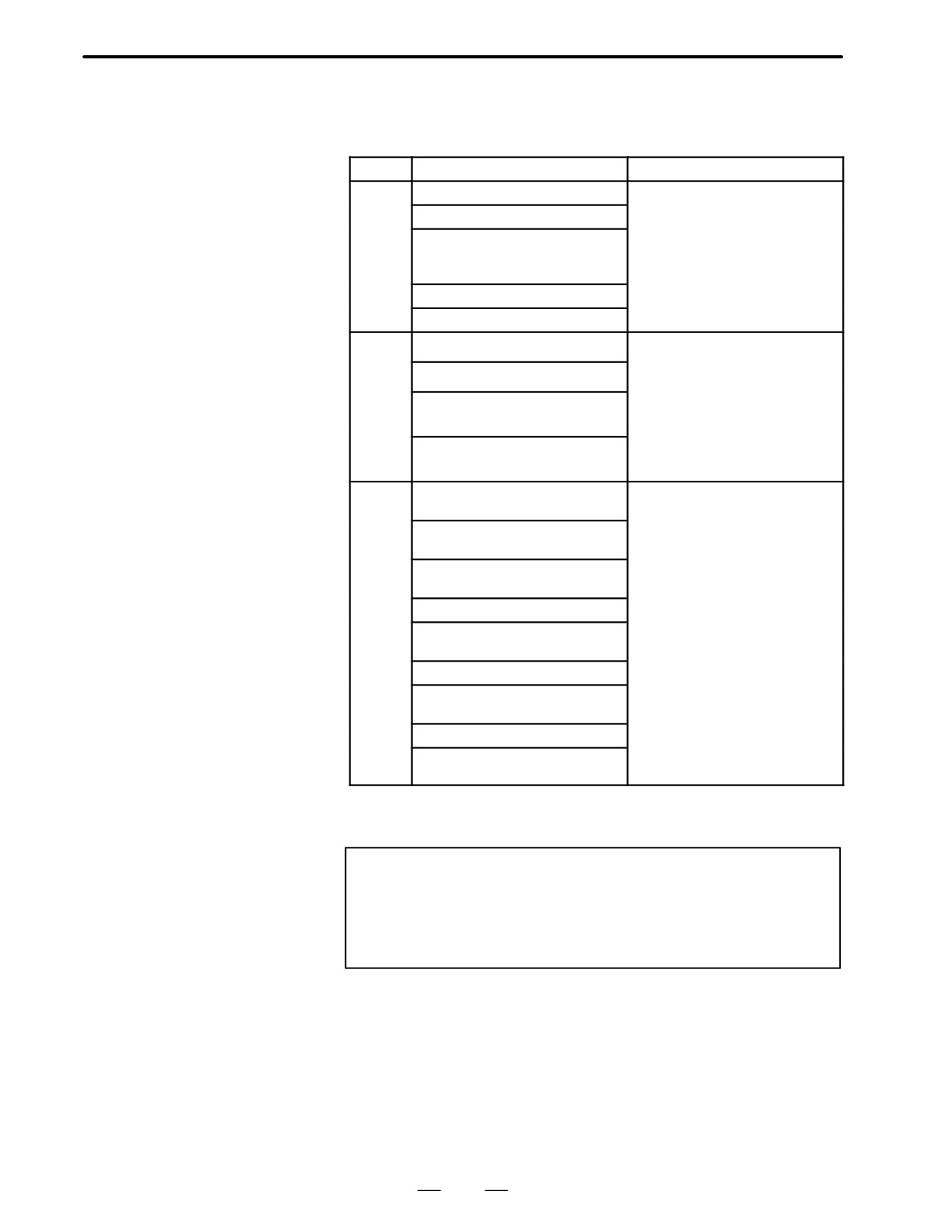
D Separating signal lines
The cables used for the CNC machine tool are classified as listed in the
following table :
Bind the cables in each group as described in the action column.
Group
Signal line
Action
A
Primary AC power line
Bind the cables in group A sepa-
rately (Note 1) from groups B and
Secondary AC power line
C or cover group A with an elec-
AC/DC power lines (containing
tromagnetic shield (Note 2).
the power lines for the servo and
spindle motors)
Connect spark killers or diodes
AC/DC solenoid
with the solenoid and relay.
AC/DC relay
B
DC solenoid (24VDC)
Connect diodes with DC solenoid
and relay.
DC relay (24 VDC)
Bind the cables in group B sepa-
rately from group A or cover group
DI/DO cable between the CNC
B with an electromagnetic shield.
and power magnetics cabinet
Separate group B as far from
group C as possible
DI/DO cable between the CNC
It is more desirable to cover group
and machine
B with the shield.
C
Cable between the CNC and
Bind the cables in group C sepa-
servo amplifier
rately from group A or cover group
C with an electromagnetic shield
Cable for position and velocity
feedback
Separate group C as far from
Cable between the CNC and
group B as possible.
spindle amplifier
Be sure to perform shield proces-
Cable for the position coder
sing
Cable for the manual pulse gener-
ator
Cable between the CRT and MDI
RS232C and RS422 interface
cables
Cable for the battery
Other cables to be covered with
the shield
Notes
1
The groups must be 10 cm or more apart from one another
when binding the cables in each group.
2
The electromagnetic shield refers to shielding between
groups with grounded steel plates.
121
2. HARDWARE
B-62445E/03
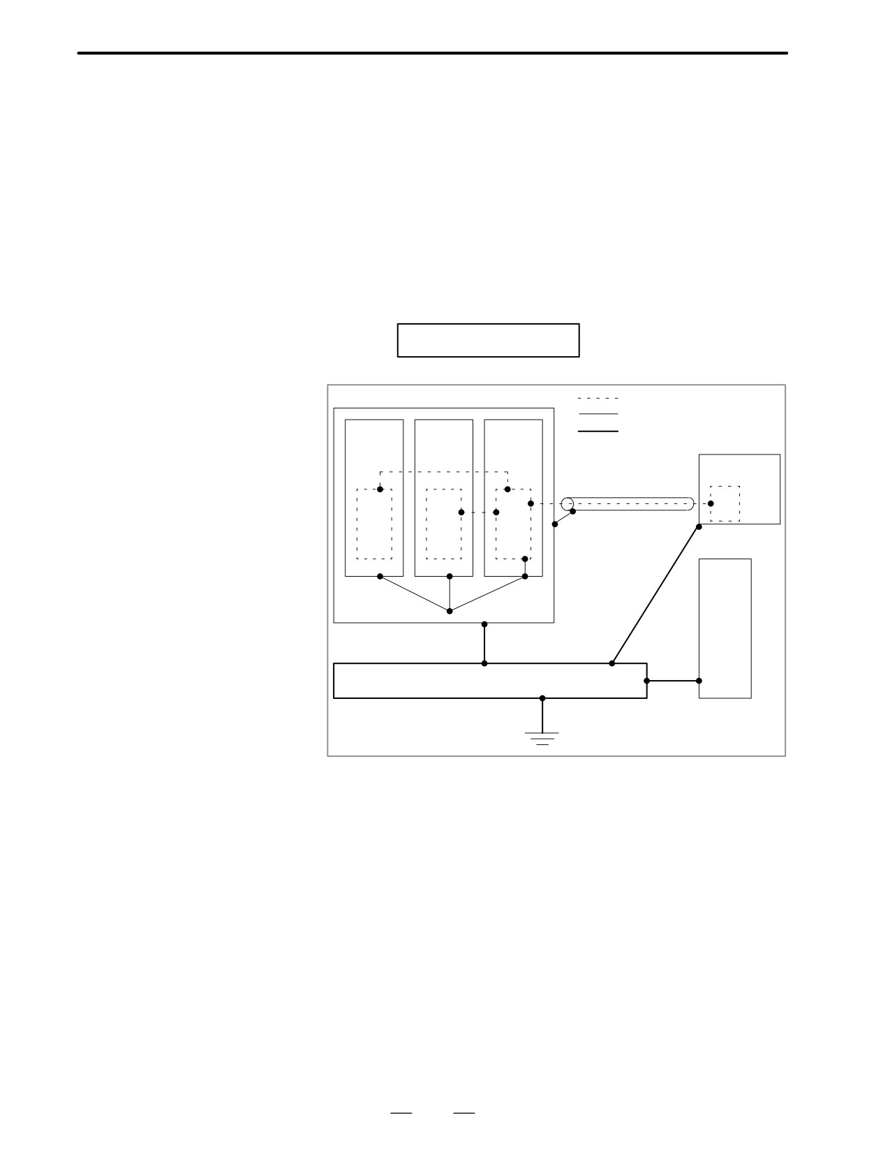
D Ground
The following ground systems are provided for the CNC machined tool:
1. Signal ground system (SG)
The signal ground (SG) supplies the reference voltage (0V ) of the
electrical signal system to the machine.
2. Frame ground system (FG)
The frame ground system (FG) is used for safety, and suppressing
external and internal noises. In the frame ground system, the frames
and cases of the units, panels, and shields for the interface cables
between the units are connected.
3. System ground system
The system ground system is used to connect the frame ground
systems connected between devices or units with the
ground. Notes on connecting the
ground systems
Signal ground system
Frame ground system
System ground system
Power
Servo
CNC
mag-
amplifi-
control
netics
er
unit
Operator’s
unit
panel
Machine
tool
Power magnet-
ics cabinet
Distribution board
⋅
Connect the signal gournd with the frame ground (FG) at only one
place in the CNC control unit.
⋅
The grounding resistance of the system gorund shall be 100 ohms or
less (class 3 grounding).
⋅
The system ground cable must have enough cross-sectional area to
safely carry the accidental current flow into the system gound when
an accident such as a short circuit occurs.
(Generally, it must have the cross-sectional area of the AC power
cable or more.)
⋅
Use the cable containing the AC power wire and the system gound
wire so that power is supplied with the ground wire connected.
122
2. HARDWARE
B-62445E/03
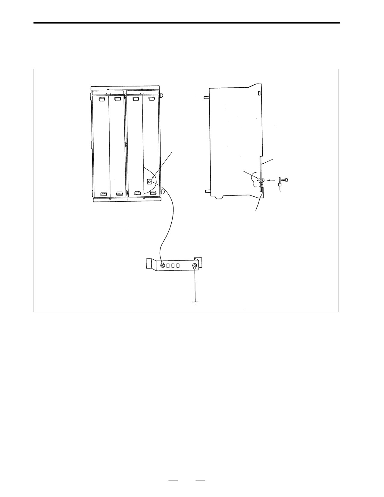
D Connecting the signal
ground (SG) of the
control unit
Control unit
M3 or M4 terminal
for signal ground
Printed cir-
(SG)
cuit board
SG
M3
Ground cable
Ground cable:
wire with a sectional area
of 2mm2 or more
F r a m e
Ground plate of
System ground
ground
=
the cabinet
(FG)
Connect the 0 V line of the electronic circuit in the control unit with the
ground plate of the cabinet via the signal ground (SG) terminal.
The SG terminal is located on the printed circuit board at the rear of the
control unit.
123
2. HARDWARE
B-62445E/03
D Noise suppressor
The AC/DC solenoid and relay are used in the power magnetics cabinet.
A high pulse voltage is caused by coil inductance when these devices are
turned on or off.
This pulse voltage induced through the cable causes the electronic circuits
to be disturbed.
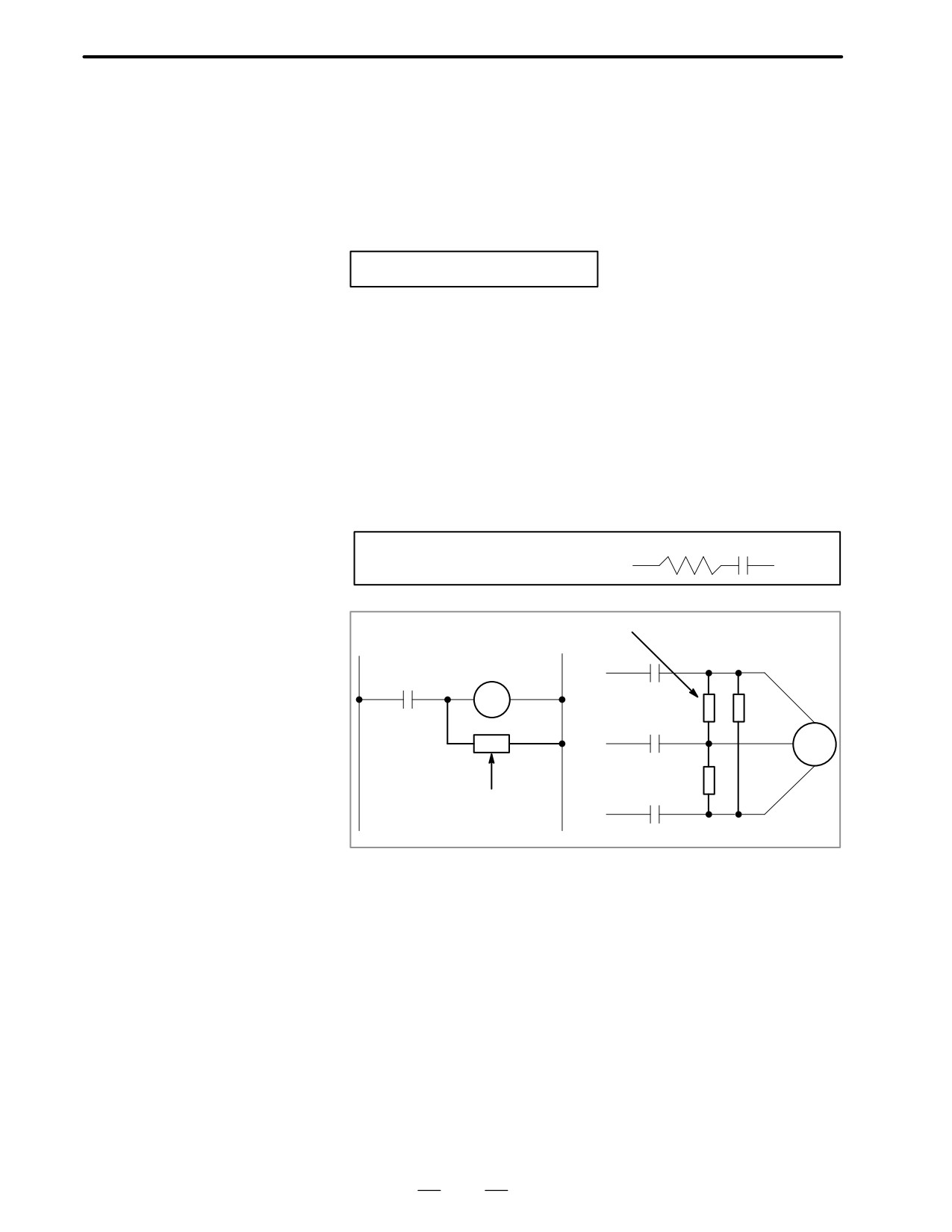
To reduce the pulse voltage, use a spark killer for an AC device or a diode
for a DC device.
Notes on selecting the spark killer
Use a spark killer consisting of a resistor and capacitor in series. This type
of spark killer is called a CR spark killer.
(A varistor is useful in clamping the peak voltage of the pulse voltage, but
cannot suppress the sudden rise of the pulse voltage. FANUC therefore
recommends a CR spark killer.)
The reference capacitance and resistance of the spark killer shall conform
to the following based on the current (1(A)) and DC resistance of the
stationary coil :
1) Resistance (R):Equivalent to DC resistance of the coil
2) Capacitance (C):
I2
-
I2
(µF)
10
20
R
C
Equivalent circuit of the spark killer
Spark killer
AC relay
Motor
Spark killer
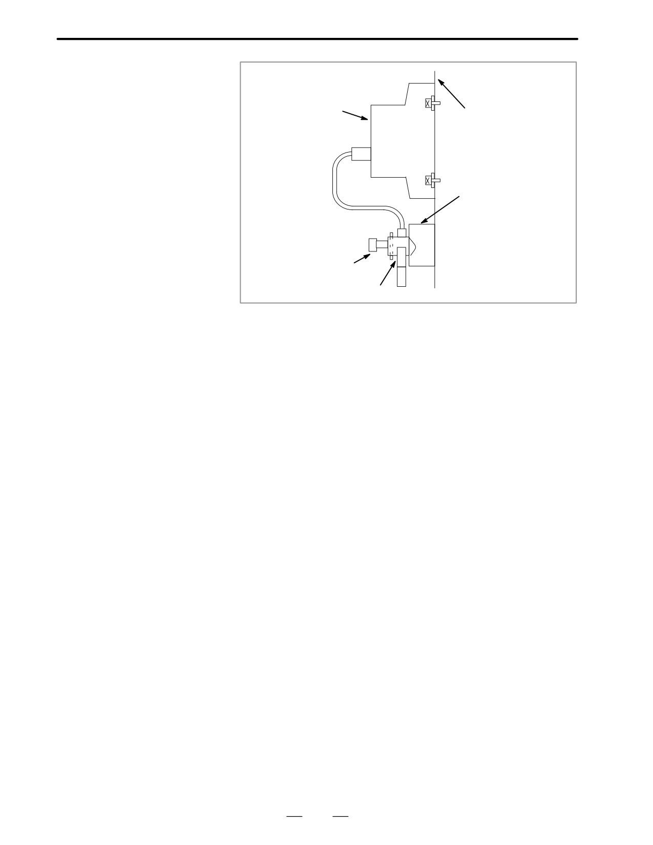
D Cable clamp and shield
The CNC cables that required shielding should be clamped by the method
processing
shown below. This cable clamp treatment is for both cable support and
proper grounding of the shield. To insure stable CNC system operation,
follow this cable clamp method.
Partially peel out the sheath and expose the shield. Push and clamp by
the plate metal fittings for clamp at the part. Metal fittings for clamp are
attached to the control unit. The ground plate must be made by the
machine tool builder, and set as follows:
124
2. HARDWARE
B-62445E/03
ÇÇ
ÇÇ
Control unit
ÇÇ
Machine side
ÇÇinstallation
board
ÇÇ
ÇÇ
ÇÇ
Ground plate
ÇÇ
ÇÇ
ÇÇ
ÔÔÕ
ÇÇ
Metal fittings
for clamp
Õ ÇÇ
ÔÔ
Õ ÇÇ
Shield cover
ÇÇ
125
2. HARDWARE
B-62445E/03
2.5
LED DISPLAY AND
MODULE
CONFIGURATION OF
PCB
2.5.1
Power supply unit
Name
Code
Power supply unit AI
A16B-1212-0900
A16B-1212-0901
Power supply unit BI
A16B-1212-0870
A16B-1212-0871
Power supply unit C
A20B-1005-0420
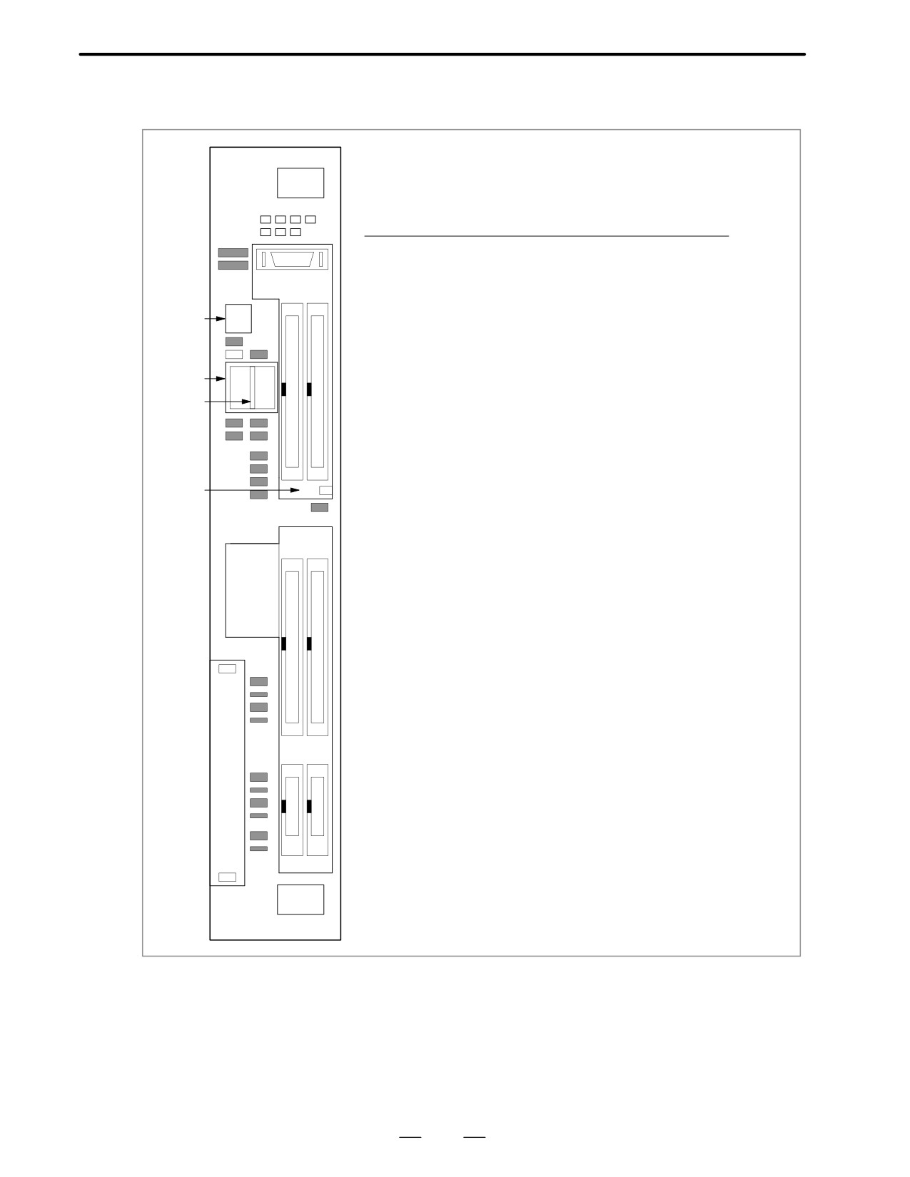
D LED display
This LED is lit when the input AC power voltage is sup-
PIL(Green)
plied to CP1.
This LED is lit when overcurrent,overvoltage, or low volt-
ALM(Red)
age occurs in direct current output voltage.
D Disposition of
Connector, etc.
D In case of Power supply
AI and BI
CP1
(AC IN)
F1
CP2
CP3
(AC OUT)
(AC OUT)
Battery case
PIL
LED
ALM
CP4
(CONTROL)
CP5
CP6
(24V)
(24E)
F3
F4
Locations of connectors and fuses
126
2. HARDWARE
B-62445E/03
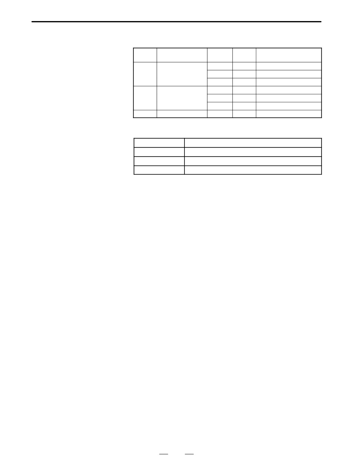
D In case of power supply
C
I/O
PSU
Connector
Function
Abbreriation
number
1
Fuse
1
2
2
24 V Input
DC IN
CP1A
3
3
24 V Output
DC OUT
CP1B
4
4
Battery
CP8
5
Battery case
5
127
2. HARDWARE
B-62445E/03
D Fuse
Fuses
Power
Symbol
Rating
Ordering code
Individual code
supply
F1
7.5A
A60L-0001-0245#GP75
AI
A02B-0200-K100
F3
3.2A
A60L-0001-0075#3.2
F4
5A
A60L-0001-0046#5.0
F1
7.5A
A60L-0001-0245#GP75
BI
A02B-0200-K101
F3
5A
A60L-0001-0075#5.0
F4
5A
A60L-0001-0046#5.0
C
A02B-0177-K101
-
7.5A
A60L-0001-0046#7.5R
Circuit protected by fuses
Symbol
Use
F1
200-VAC input
F3
Power supply for 9I monochrome CRT or LCD
F4
I/O unit, etc.
D Battery
Lithium battery code : A98L-0031-0012
128
2. HARDWARE
B-62445E/03
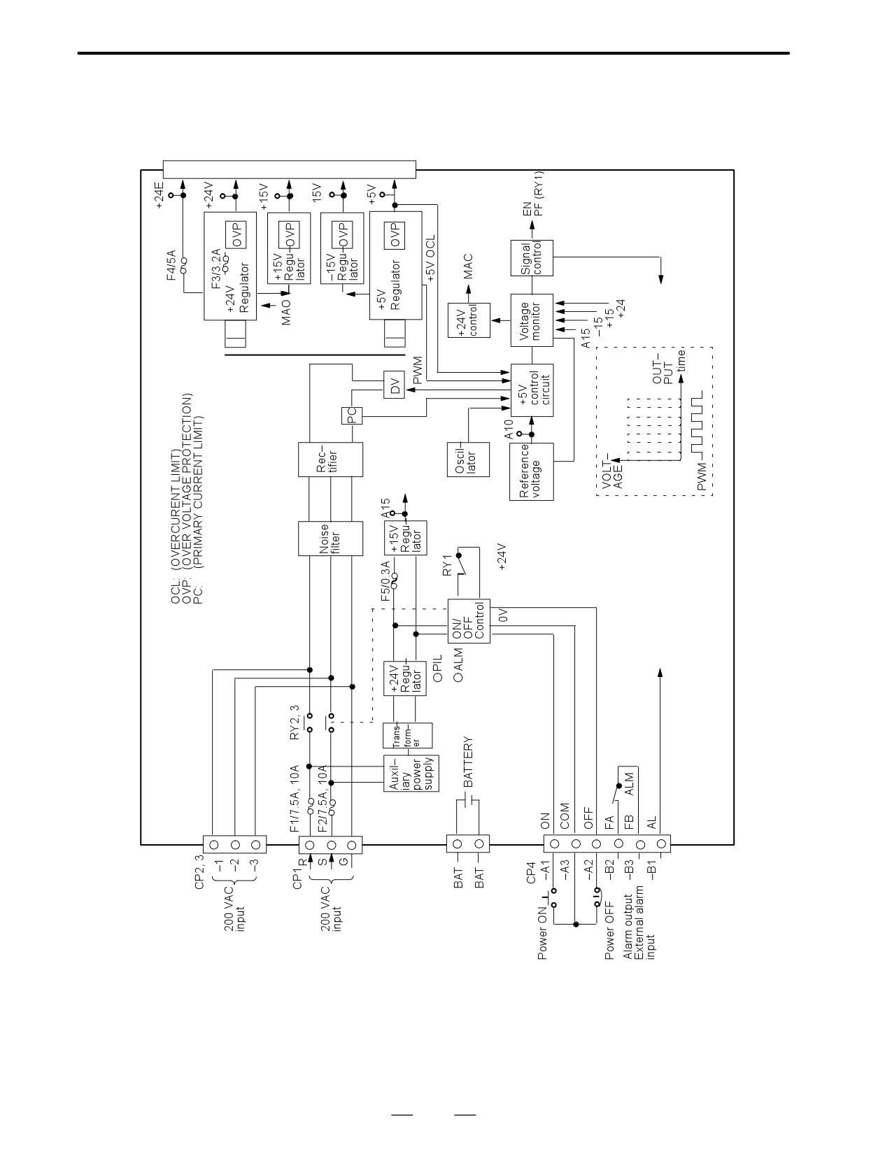
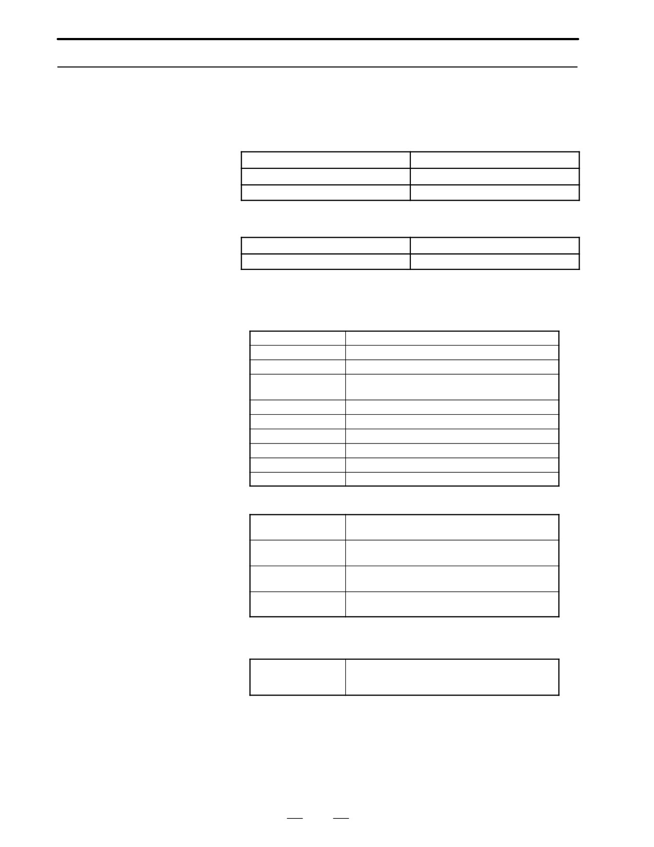
D Block diagram for power
supply unit (AI and BI)
*
*
129
2. HARDWARE
B-62445E/03
2.5.2
Main CPU Board
D Series16
MAIN-A⋅4-axis specification
Main CPU Board
Name
Code
Main CPU board
A16B-3200-0010
Main CPU board
A16B-3200-0170
MAIN-B⋅6-axis specification
Name
Code
Main CPU board
A16B-3200-0110
D LED display
1
LED status in power on routine (Green LED)
j:OFF J:ON
STATUS jjjj
Power OFF
STATUS JJJJ
Initial status after power on (CPU is not run yet)
STATUS JjJJ
Waiting for other CPU’s answer (ID setting)
STATUS jjJJ
Detect other CPU’s answer (Finished of ID set-
ting)
STATUS JJjJ
FANUC BUS initialized
STATUS jJjJ
PMC initialization (1) finished
STATUS JjjJ
All PCBs configuration finished
STATUS JJJj
PMC initial running finished (PMC-RB only)
STATUS jJJj
Waiting for digital servo initialization
STATUS Jjjj
All initialized, running
2
LED status in power of alarm j:OFF J:ON
:Don’s care
STATUS jJjj
RAM parity alarm occured in main CPU board
ALARM JJj
or servo alarm occured in OPTION-2 board
STATUS jJjj
Servo alarm (watch dog alarm) occured
ALARM jJJ
STATUS jJjj
Other system alarm occured
ALARM jJj
STATUS JJJJ
The system is stopped before the CPU is acti-
ALARM J
vated
3
LED display when the system, fitted with option 2 board (with
sub-CPU), is not started
j:OFF J:ON
STATUS JJjj
An error occurred in the BASIC SRAM of the
ALARM jjj
option 2 board (with sub-CPU). Replace the
option 2 board.
130
2. HARDWARE
B-62445E/03
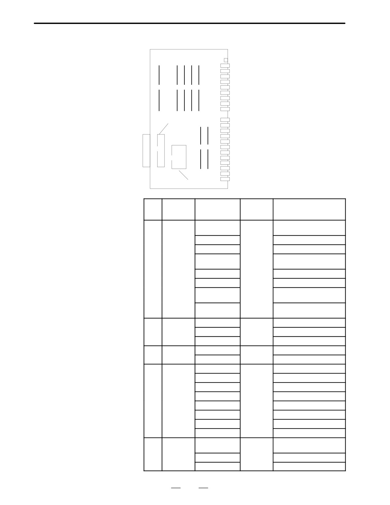
D D Location of modules
A16B-3200-0010
Connector Connector
LED
name
number Use
CRT
JA1
CRT video signal
MDI
JA2
MDI keyboard
R232-1
JD5A
RS-232-C serial port
R232-2
JD5B
RS-232-C serial port
(1)
(2
(3)
(4
(5)
MPG
JA3
Manual pulse generator
IOLINK
JD1A
FANUC I/O LINK
SPDL-1
JA7A
Serial spindle
A-OUT1
JA8A
Analog output
APCBAT
JA4A
Battery for use with the APC
Connector
AMP1
JV1
Axis 1 servo amplifier
for add on
AMP2
JV2
Axis 2 servo amplifier
AMP3
JV3
Axis 3 servo amplifier
board
AMP4
JV4
Axis 4 servo amplifier
ENC1
JF1
Axis 1 pulse coder
(6
(7)
ENC2
JF2
Axis 2 pulse coder
(8)
ENC3
JF3
Axis 3 pulse coder
(9)
ENC4
JF4
Axis 4 pulse coder
SCALE1
JF21
Axis 1 scale
SCALE2
JF22
Axis 2 scale
SCALE3
JF23
Axis 3 scale
ROM for
SCALE4
JF24
Axis 4 scale
boot
No.
Name
Specifications
Function
Display of system
configuration screen
(1)
FROM
A20B-2902-0080
CNC
FLASH ROM MODULE: 4MB
module
system,
ADDITIONAL SRAM: 512KB
servo
A20B-2902-0081
FLASH ROM MODULE: 4MB
system,
A20B-2902-0082
graphic
FLASH ROM MODULE: 2MB
system,
A20B-2902-0090
FLASH ROM MODULE: 8MB
Additional
ADDITIONAL SRAM: 2MB
SRAM
A20B-2902-0091
FLASH ROM MODULE: 8MB
A20B-2902-0092
FLASH ROM MODULE: 6MB
A20B-2902-0093
FLASH ROM MODULE: 8MB
ADDITIONAL SRAM: 512KB
A20B-2902-0094
FLASH ROM MODULE: 6MB
ADDITIONAL SRAM: 512KB
(2)
DRAM
A20B-2901-0940
RAM for the
RAM: 6MB
module
CNC
A20B-2901-0941
RAM: 4MB
system
A20B-2901-0942
RAM: 2MB
(3)
PMC
A20B-2901-0960
PMC control
PMC MODULE: PMP2 + SLC
module
A20B-2901-0961
PMC MODULE: PMP2
(4)
CRTC
A20B-2902-0270
CRT
CRTC MODULE: 14I CRT
module
text display
A20B-2902-0271
CRTC MODULE: 9I CRT
control
A20B-2902-0272
CRTC MODULE: VGA
A20B-2902-0273
CRTC MODULE: 14I CRT
A20B-2902-0275
CRTC MODULE: VGA
A20B-2902-0276
CRTC MODULE: 9I CRT
A20B-2902-0277
CRTC MODULE: 9I CRT
A20B-2902-0278
CRTC MODULE: VGA
(5)
Spindle
A20B-2901-0980
Spindle
SERIAL SPINDLE LSI
module
control
ANALOG SPINDLE LSI
A20B-2901-0981
SERIAL SPINDLE LSI
A20B-2901-0982
ANALOG SPINDLE LSI
131
2. HARDWARE
B-62445E/03
No.
Name
Specifications
Function
Display of system
configuration screen
(6)
Servo
A20B-2902-0060
Servo
SERVO 3/4 AXIS
module
control
A20B-2902-0061
3 or 4 axis
(7)
Servo
A20B-2902-0060
Servo
SERVO 1/2 AXIS
module
control
A20B-2902-0061
1 or 2 axis
Add on board
No.
Name
Specifications
Function
Display of system
configuration screen
(8)
Graphic
A20B-8200-0010
Graphic
GRAPHIC ENGINE FUNC-
function
display
TION
A20B-8200-0011
board
control
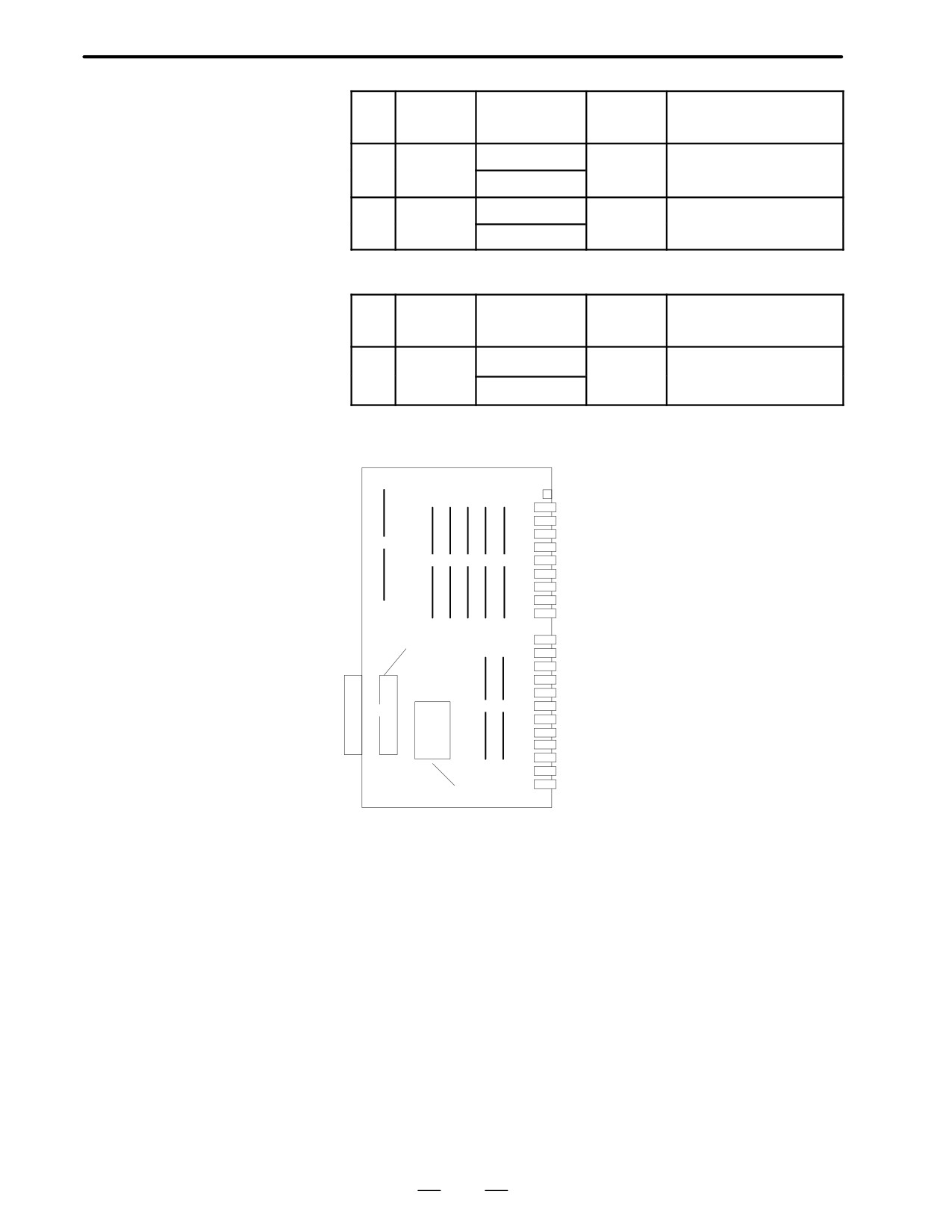
D Location of modules
Connector Connector
A16B-3200-0170
name
number Use
LED
CRT
JA1
CRT video signal
MDI
JA2
MDI keyboard
R232-1
JD5A
RS-232-C serial port
(1)
R232-2
JD5B
RS-232-C serial port
(2
(3)
(4
(5)
(6)
MPG
JA3
Manual pulse generator
IOLINK
JD1A
FANUC I/O LINK
SPDL-1
JA7A
Serial spindle
A-OUT1
JA8A
Analog output
APCBAT
JA4A
Battery for use with the APC
Connector
AMP1
JV1
Axis 1 servo amplifier
AMP2
JV2
Axis 2 servo amplifier
for add on
AMP3
JV3
Axis 3 servo amplifier
board
AMP4
JV4
Axis 4 servo amplifier
ENC1
JF1
Axis 1 pulse coder
(7
(8)
ENC2
JF2
Axis 2 pulse coder
(9)
ENC3
JF3
Axis 3 pulse coder
(10)
ENC4
JF4
Axis 4 pulse coder
SCALE1
JF21
Axis 1 scale
SCALE2
JF22
Axis 2 scale
SCALE3
JF23
Axis 3 scale
ROM for
SCALE4
JF24
Axis 4 scale
boot
132
2. HARDWARE
B-62445E/03
No.
Name
Specifications
Function
Display of system
configuration screen
(1)
DRAM
A20B-2901-0940
CNC
DRAM:6MB
module
system
A20B-2901-0941
DRAM:4MB
RAM
A20B-2901-0942
DRAM:2MB
(2)
SRAM
A20B-2902-0350
Expanded
ADDITIONAL SRAM:256KB
module
SRAM
A20B-2902-0351
ADDITIONAL SRAM:768KB
A20B-2902-0352
ADDITIONAL SRAM:2.25MB
(3)
FROM
A20B-2902-0341
CNC sys-
FLASH ROM MODULE:4MB
module
tem, Servo
A20B-2902-0343
system
FLASH ROM MODULE:2MB
Graphic
A20B-2902-0410
system,
FLASH ROM MODULE:8MB
SRAM for
A20B-2902-0411
system
FLASH ROM MODULE:6MB
(4)
PMC
A20B-2901-0960
PMC control
PMC MODULE:PMP2+SLC
module
A20B-2901-0961
PMC MODULE:PMP2
(5)
CRTC
A20B-2902-0270
CRT text
CRTC MODULE:14”CRT
module
display
A20B-2902-0271
CRTC MODULE:9”CRT
control
A20B-2902-0272
CRTC MODULE:VGA
A20B-2902-0273
CRTC MODULE:14”CRT
A20B-2902-0275
CRTC MODULE:VGA
A20B-2902-0276
CRTC MODULE:9”CRT
A20B-2902-0277
CRTC MODULE:9”CRT
A20B-2902-0278
CRTC MODULE:VGA
(6)
Spindle
A20B-2901-0980
Spindle
SERIAL SPINDLE LSI
module
control
ANALOG SPINDLE LSI
A20B-2901-0981
SERIAL SPINDLE LSI
A20B-2901-0982
ANALOG SPINDLE LSI
(7)
Servo
A20B-2902-0060
Servo con-
SERVO 3/4 AXIS
module
trol 3rd or
A20B-2902-0061
4th axis
(8)
Servo
A20B-2902-0060
Servo con-
SERVO 1/2 AXIS
module
trol 1st or
A20B-2902-0061
2nd axis
Add on board
No.
Name
Specifications
Function
Display of system
configuration screen
(8)
Graphic
A20B-8200-0010
Graphic
GRAPHIC ENGINE FUNC-
function
display
TION
A20B-8200-0011
board
control
133
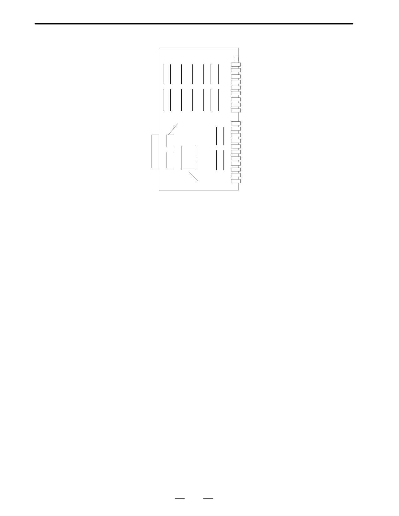
2. HARDWARE
B-62445E/03
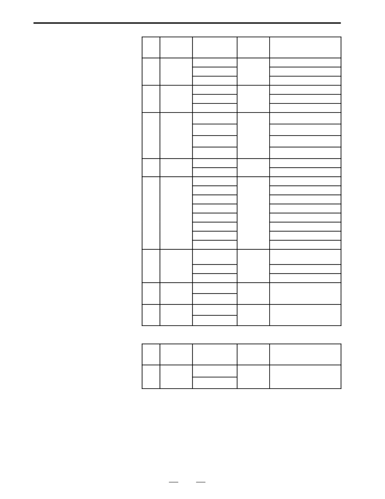
D Location of modules
A16B-3200-0110
Connector Connector
LED
name
number Use
(Total version of PC
board is 04A or older)
CRT
JA1
CRT video signal
MDI
JA2
MDI keyboard
R232-1
JD5A
RS-232-C serial port
R232-2
JD5B
RS-232-C serial port
(1
(2)
(3)
(4)
(5
(6)
(7)
MPG
JA3
Manual pulse generator
IOLINK JD1A
FANUC I/O LINK
SPDL-1
JA7A
Serial spindle
A-OUT1 JA8A
Analog output
APCBAT JA4A
Battery for use with the
APC
Connector
SERVO1 JS1A Axis 1 servo amplifier
for add on
SERVO2 JS2A Axis 2 servo amplifier
board
SERVO3 JS3A Axis 3 servo amplifier
SERVO4 JS4A Axis 4 servo amplifier
(8
(9)
SERVO5 JS5A
Axis 5 servo amplifier
(10)
SERVO6 JS6A
Axis 6 servo amplifier
(11)
SCALE1 JF21
Axis 1 scale
SCALE2 JF22
Axis 2 scale
SCALE3 JF23
Axis 3 scale
SCALE4 JF24
Axis 4 scale
ROM for
SV-CHK JA26
SERVO CHECK
boot
134
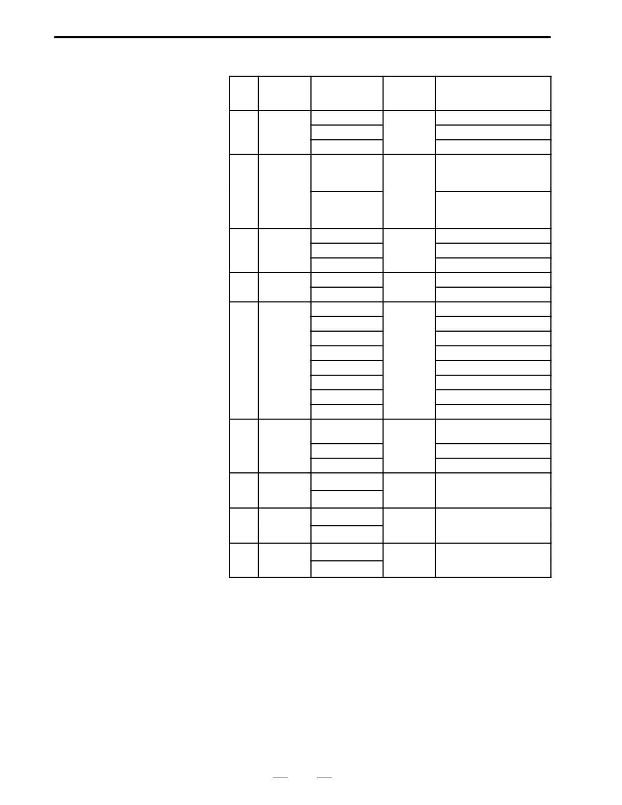
2. HARDWARE
B-62445E/03
No.
Name
Specifications
Function
Display of system
configuration screen
(1)
SRAM
A20B-2902-0350
Expanded
ADDITIONAL SRAM:256KB
module
SRAM
A20B-2902-0351
ADDITIONAL SRAM:768KB
A20B-2902-0352
ADDITIONAL SRAM:2.25MB
(2)
FROM
A20B-2902-0341
CNC sys-
FLASH ROM MODULE:4MB
module
tem, Servo
system
Graphic
A20B-2902-0343
system,
FLASH ROM MODULE:2MB
SRAM for
system
(3)
DRAM
A20B-2901-0940
CNC
DRAM:6MB
module
system
A20B-2901-0941
DRAM:4MB
RAM
A20B-2901-0942
DRAM:2MB
(4)
PMC
A20B-2901-0960
PMC control
PMC MODULE:PMP2+SLC
module
A20B-2901-0961
PMC MODULE:PMP2
(5)
CRTC
A20B-2902-0270
CRT text
CRTC MODULE:14”CRT
module
display
A20B-2902-0271
CRTC MODULE:9”CRT
control
A20B-2902-0272
CRTC MODULE:VGA
A20B-2902-0273
CRTC MODULE:14”CRT
A20B-2902-0275
CRTC MODULE:VGA
A20B-2902-0276
CRTC MODULE:9”CRT
A20B-2902-0277
CRTC MODULE:9”CRT
A20B-2902-0278
CRTC MODULE:VGA
(6)
Spindle
A20B-2901-0980
Spindle
SERIAL SPINDLE LSI
module
control
ANALOG SPINDLE LSI
A20B-2901-0981
SERIAL SPINDLE LSI
A20B-2901-0982
ANALOG SPINDLE LSI
(7)
Servo
A20B-2902-0060
Servo con-
SERVO 1/2 AXIS
module
trol 1st or
A20B-2902-0061
2nd axis
(8)
Servo
A20B-2902-0060
Servo con-
SERVO 5/6 AXIS
module
trol 5th or
A20B-2902-0061
6th axis
(9)
Servo
A20B-2902-0060
Servo con-
SERVO 3/4 AXIS
module
trol 3rd or
A20B-2902-0061
4th axis
135
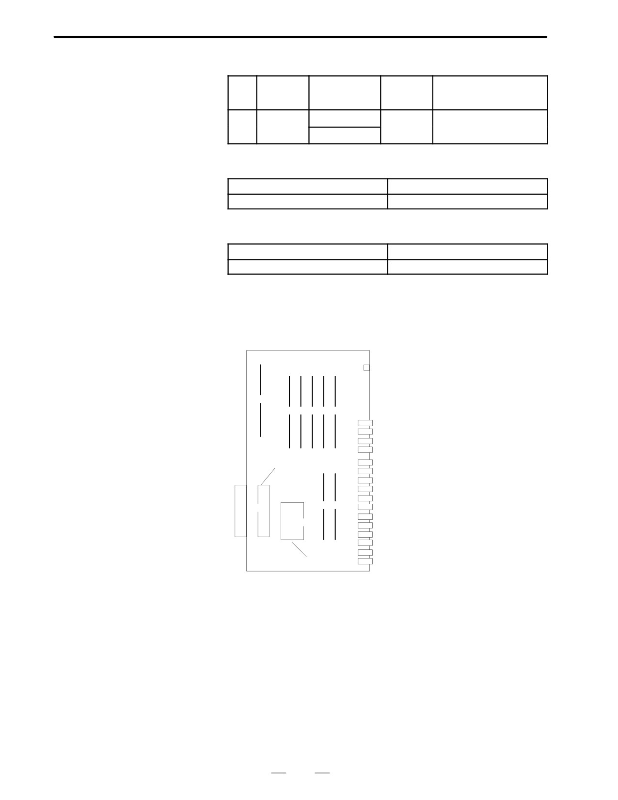
2. HARDWARE
B-62445E/03
Add on board
No.
Name
Specifications
Function
Display of system
configuration screen
(8)
Graphic
A20B-8200-0010
Graphic dis-
GRAPHIC ENGINE FUNC-
function
play control
TION
board
A20B-8200-0011
D Series18
MAIN-B⋅4-axis specification
Main CPU Board
Name
Code
Main CPU board
A16B-2202-0860
MAIN-B⋅6-axis specification
Name
Code
Main CPU board
A16B-3200-0160
D LED display
LED display is same as Series 16. See P130.
D Location of modules
A16B-2202-0860
Connector Connector
name
number Use
LED
(1)
(2
(3)
(4
(5
(6)
CRT
JA1
CRT video signal
MDI
JA2
MDI keyboard
R232-1
JD5A
RS-232-C serial port
R232-2
JD5B
RS-232-C serial port
MPG
JA3
Manual pulse generator
Connector
IOLINK
JD1A
FANUC I/O LINK
for add on
SPDL-1
JA7A
Serial spindle
board
A-OUT1
JA8A
Analog output
AMP1
JS1A
Axis 1 servo amplifier
(9)
(7
(8)
AMP2
JS2A
Axis 2 servo amplifier
AMP3
JS3A
Axis 3 servo amplifier
(10)
AMP4
JS4A
Axis 4 servo amplifier
SCALE1 JF21
Axis 1 scale
SCALE2 JF22
Axis 2 scale
SCALE3 JF23
Axis 3 scale
ROM for
SCALE4 JF24
Axis 4 scale
boot
136
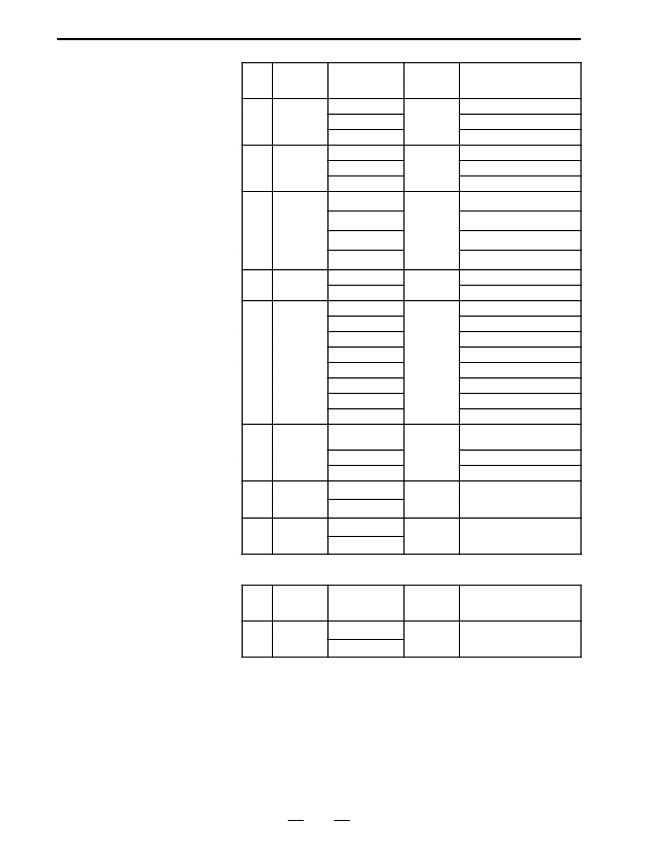
2. HARDWARE
B-62445E/03
No.
Name
Specifications
Function
Display of system
configuration screen
(1)
DRAM
A20B-2901-0940
CNC
DRAM:6MB
module
system
A20B-2901-0941
DRAM:4MB
RAM
A20B-2901-0942
DRAM:2MB
(2)
SRAM
A20B-2902-0350
Expanded
ADDITIONAL SRAM:256KB
module
SRAM
A20B-2902-0351
ADDITIONAL SRAM:768KB
A20B-2902-0352
ADDITIONAL SRAM:2.25MB
(3)
FROM
A20B-2902-0341
CNC sys-
FLASH ROM MODULE:4MB
module
tem, Servo
A20B-2902-0343
system
FLASH ROM MODULE:2MB
Graphic
A20B-2902-0410
system,
FLASH ROM MODULE:8MB
SRAM for
A20B-2902-0411
system
FLASH ROM MODULE:6MB
(4)
PMC
A20B-2901-0960
PMC control
PMC MODULE:PMP2+SLC
module
A20B-2901-0961
PMC MODULE:PMP2
(5)
CRTC
A20B-2902-0270
CRT text
CRTC MODULE:14”CRT
module
display
A20B-2902-0271
CRTC MODULE:9”CRT
control
A20B-2902-0272
CRTC MODULE:VGA
A20B-2902-0273
CRTC MODULE:14”CRT
A20B-2902-0275
CRTC MODULE:VGA
A20B-2902-0276
CRTC MODULE:9”CRT
A20B-2902-0277
CRTC MODULE:9”CRT
A20B-2902-0278
CRTC MODULE:VGA
(6)
Spindle
A20B-2901-0980
Spindle
SERIAL SPINDLE LSI
module
control
ANALOG SPINDLE LSI
A20B-2901-0981
SERIAL SPINDLE LSI
A20B-2901-0982
ANALOG SPINDLE LSI
(7)
Servo
A20B-2902-0060
Servo con-
SERVO 3/4 AXIS
module
trol 3rd or
A20B-2902-0061
4th axis
(8)
Servo
A20B-2902-0060
Servo con-
SERVO 1/2 AXIS
module
trol 1st or
A20B-2902-0061
2nd axis
Add on board
No.
Name
Specifications
Function
Display of system
configuration screen
(8)
Graphic
A20B-8200-0010
Graphic dis-
GRAPHIC ENGINE FUNC-
function
play control
TION
board
A20B-8200-0011
137
2. HARDWARE
B-62445E/03
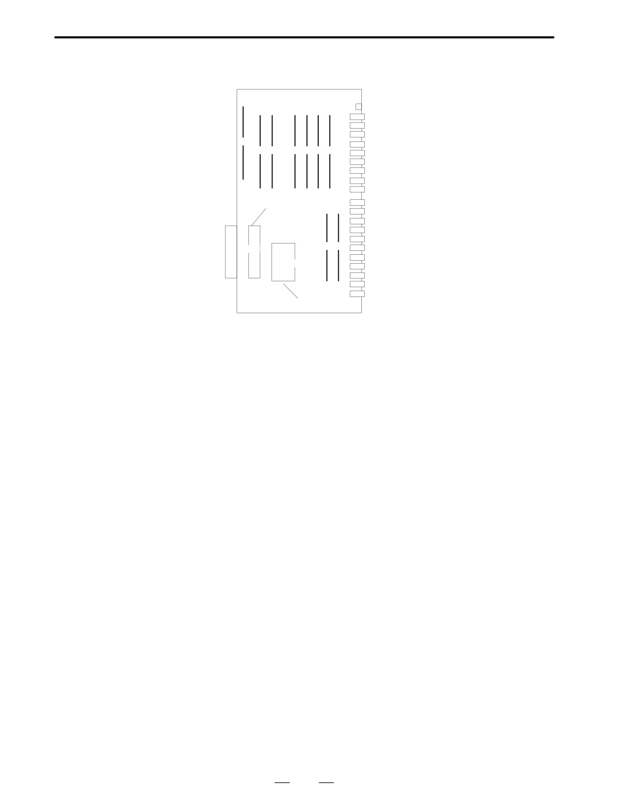
D Location of modules
A16B-3200-0160
Connector Connector
name
number
Use
LED
CRT
JA1
CRT video signal
MDI
JA2
MDI keyboard
R232-1
JD5A
RS-232-C serial port
(1)
R232-2
JD5B
RS-232-C serial port
(2)
(3)
(4)
(5
(6
(7)
MPG
JA3
Manual pulse generator
IOLINK
JD1A
FANUC I/O LINK
SPDL-1
JA7A
Serial spindle
A-OUT1 JA8A
Analog output
APCBAT JA4A
Battery for use with the APC
Connector
SERVO1 JS1
Axis 1 servo amplifier
for add on
SERVO2 JS2
Axis 2 servo amplifier
board
SERVO3 JS3
Axis 3 servo amplifier
SERVO4 JS4
Axis 4 servo amplifier
SERVO5 JS5
Axis 5 servo amplifier
(8
(9)
(10)
SERVO6 JS6
Axis 6 servo amplifier
SCALE1 JF21
Axis 1 scale
(11)
SCALE2 JF22
Axis 2 scale
SCALE3 JF23
Axis 3 scale
SCALE4 JF24
Axis 4 scale
SV-CHK JA26
SERVO CHECK
ROM for
boot
138
2. HARDWARE
B-62445E/03
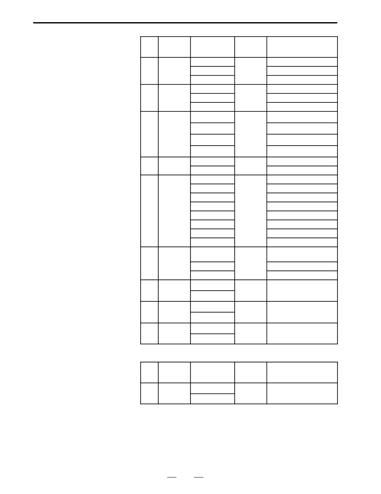
No.
Name
Specifications
Function
Display of system
configuration screen
(1)
DRAM
A20B-2901-0940
CNC
DRAM:6MB
module
system
A20B-2901-0941
DRAM:4MB
RAM
A20B-2901-0942
DRAM:2MB
(2)
SRAM
A20B-2902-0350
Expanded
ADDITIONAL SRAM:256KB
module
SRAM
A20B-2902-0351
ADDITIONAL SRAM:768KB
A20B-2902-0352
ADDITIONAL SRAM:2.25MB
(3)
FROM
A20B-2902-0341
CNC sys-
FLASH ROM MODULE:4MB
module
tem, Servo
A20B-2902-0343
system
FLASH ROM MODULE:2MB
Graphic
A20B-2902-0410
system,
FLASH ROM MODULE:8MB
SRAM for
A20B-2902-0411
system
FLASH ROM MODULE:6MB
(4)
PMC
A20B-2901-0960
PMC control
PMC MODULE:PMP2+SLC
module
A20B-2901-0961
PMC MODULE:PMP2
(5)
CRTC
A20B-2902-0270
CRT text
CRTC MODULE:14”CRT
module
display
A20B-2902-0271
CRTC MODULE:9”CRT
control
A20B-2902-0272
CRTC MODULE:VGA
A20B-2902-0273
CRTC MODULE:14”CRT
A20B-2902-0275
CRTC MODULE:VGA
A20B-2902-0276
CRTC MODULE:9”CRT
A20B-2902-0277
CRTC MODULE:9”CRT
A20B-2902-0278
CRTC MODULE:VGA
(6)
Spindle
A20B-2901-0980
Spindle
SERIAL SPINDLE LSI
module
control
ANALOG SPINDLE LSI
A20B-2901-0981
SERIAL SPINDLE LSI
A20B-2901-0982
ANALOG SPINDLE LSI
(7)
Servo
A20B-2902-0060
Servo con-
SERVO 1/2 AXIS
module
trol 1st or
A20B-2902-0061
2nd axis
(8)
Servo
A20B-2902-0060
Servo con-
SERVO 5/6 AXIS
module
trol 5th or
A20B-2902-0061
6th axis
(9)
Servo
A20B-2902-0060
Servo con-
SERVO 3/4 AXIS
module
trol 3rd or
A20B-2902-0061
4th axis
Add on board
No.
Name
Specifications
Function
Display of system
configuration screen
(10)
Graphic
A20B-8200-0010
Graphic dis-
GRAPHIC ENGINE FUNC-
function
play control
TION
board
A20B-8200-0011
139
2. HARDWARE
B-62445E/03
2.5.3
Option 1 board
Name
Specifications
Function
Option 1 board
A16B-2200-0913
Remote buffer
A16B-2200-0914
DNC1
A16B-2200-0919
Graphic (CAP-II)
A16B-2200-0918
Graphic +Remote buffer
A16B-2200-0916
Graphic + DNC1
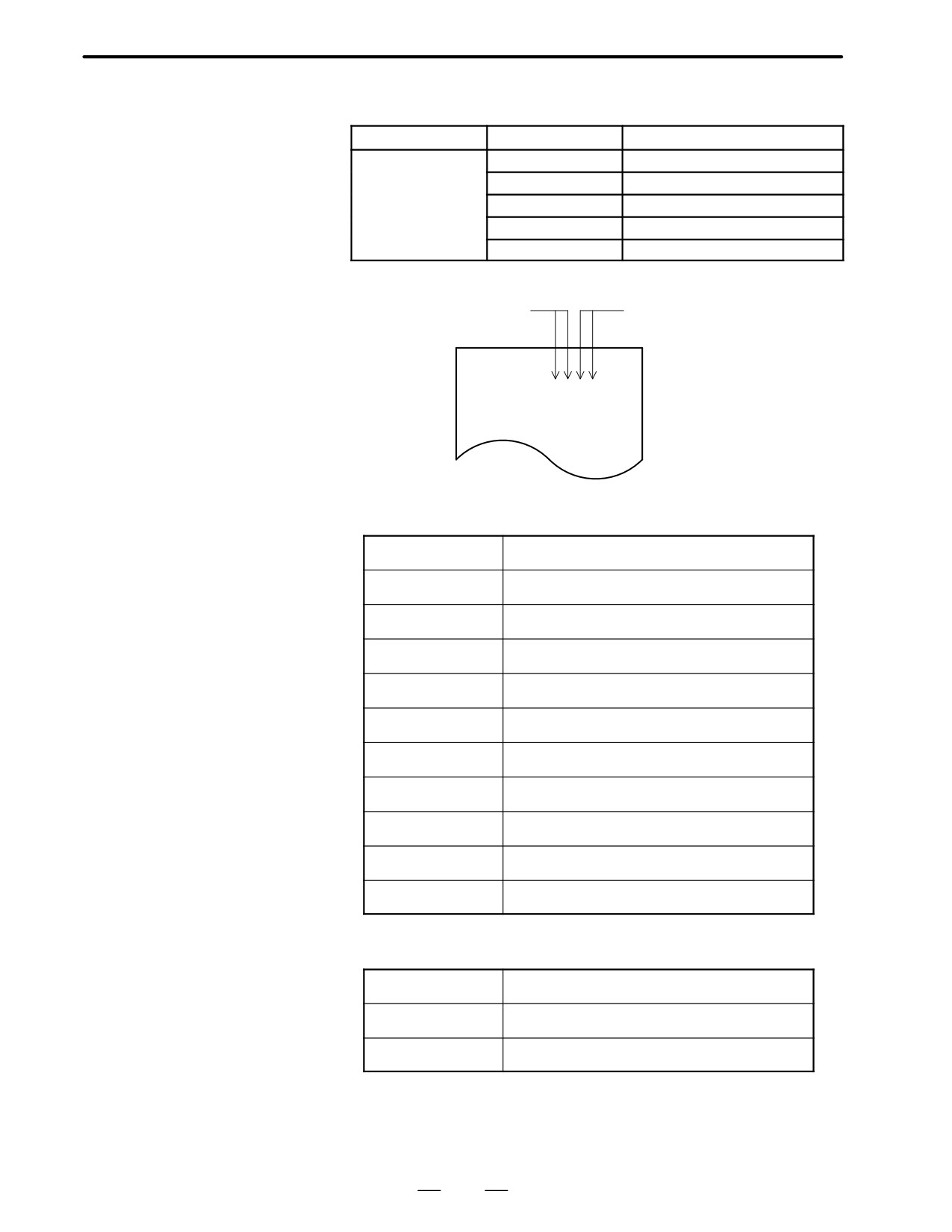
D LED display
Status of graphic function
Status of communication function
STATUS jjjj
ALARM jjj
@
Graphic function with CAP-II
j:OFF, J:ON,
:Don’t care l:Blink
STATUS JJJJ
Initial status after power on (CPU is not run yet)
ALARM Jjj
STATUS jJ
Initial status after power on (CPU is not run yet)
ALARM jjj
STATUS Jj
Waiting for other CPU’s answer (ID setting)
ALARM jjj
STATUS jj
Graphic CPU initialized, running
ALARM jjj
STATUS jJ
ROM parity error occured
ALARM Jjj
Replace the ROM module
STATUS Jj
RAM parity error occured
ALARM Jjj
Replace the OPTION 1 board
STATUS jl
Command error occured
ALARM Jjj
Replace the OPTION 1 board
STATUS ll
NMI from other PCB (LED are blinking at same time)
ALARM Jjj
Check the LED status on other PCB
STATUS lj
BUS error occured
ALARM Jjj
Replace the OPTION 1 board
STATUS lL
Divide error occured (LED are blinking alternatingly)
ALARM Jjj
Replace the OPTION 1 board
STATUS Jl
Invalid interrupt occured
ALARM Jjj
Replace the OPTION 1 board
⋅
Communication function
j:OFF, J:ON,
:Don’t care l:Blink
STATUS JJJJ
Initial status after power on (CPU is not run yet)
ALARM Jjj
STATUS
jJ
Remote buffer CPU initialized, running
ALARM jjj
STATUS
ll
Communication error occured from OPTION 1 board
ALARM jjj
140
2. HARDWARE
B-62445E/03
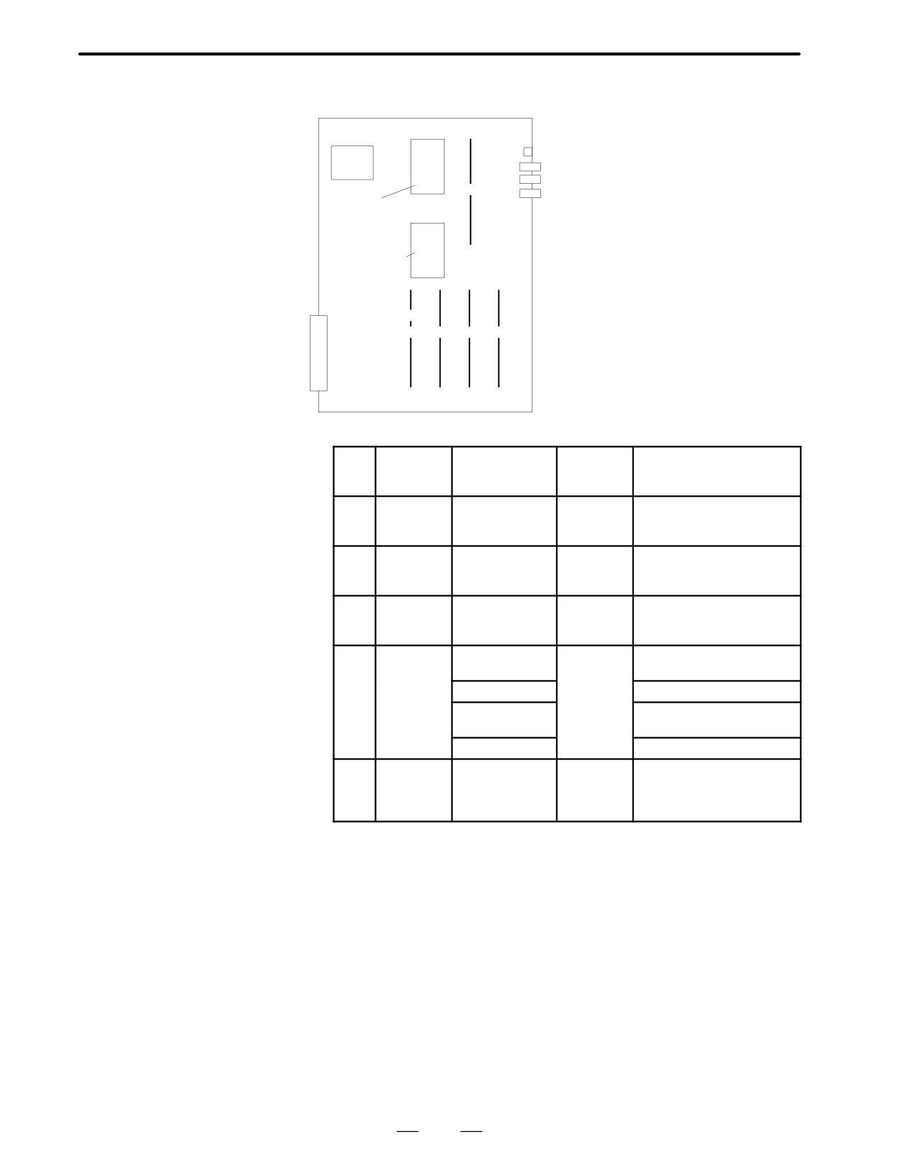
D Location of modules
Connector Connector
name
number Use
LED
CPU
CRT
JA1
CRT video signal
R232-3
JD5C
RS-232-C serial port
(5)
R422-1
JD6A
RS-422 serial port
Communication
function ROM
Graphic ROM
Module
JN
A
(1)
(2)
(3)
(4)
F-BUS
back plane
connector
D Type of modules
No.
Name
Specifications
Function
Display of system
configuration screen
(1)
Graphic
A20B-2900-0350
CPU for
Not display
CPU mod-
CAP II
ule
(2)
Graphic
A20B-2900-0311
Graphic
GRAPHIC ENGINE
engine
control for
MODULE 2
module
TT
(3)
Graphic
A20B-2900-0311
Graphic
GRAPHIC ENGINE
engine
control
MODULE 1
module
(4)
CRTC
A20B-2902-0270
CRT text
CRTC MODULE:
module
display
14”CRT
control
A20B-2902-0272
CRTC MODULE:VGA
A20B-2902-0273
CRTC MODULE:
14”CRT
A20B-2902-0275
CRTC MODULE:VGA
(5)
Commu-
A20B-2901-0361
Commu-
COMMUNICATION MODULE
nication
nication
control
control
module
141
2. HARDWARE
B-62445E/03
2.5.4
Option 2 board
Series 16
Option 2 board for MAIN-A
Name
Specifications
Function
Option 2 board
A16B-2202-0400
CPU for 2 path control + Additional
axis
Option 2 board
A16B-2202-0401
Additional axis
Option 2 board
A16B-2202-0890
CPU for 2 path control + Additional
axis
Option 2 board
A16B-2202-0891
Additional axis
Series 16
Option 2 board for MAIN-B
Name
Specifications
Function
Option 2 board
A16B-2202-0850
CPU for 2 path control + Additional
axis
Option 2 board
A16B-2202-0851
Additional axis
Series 18
Option 2 board for MAIN-B
Name
Specifications
Function
Option 2 board
A16B-2202-0853
CPU for 2 path control + Additional
axis
142
2. HARDWARE
B-62445E/03
D LED display
⋅
LED display transition when the power is turned onj:OFF, J:ON
The STATUS LEDs are green and the ALARM LEDs are red.
No.
LED display
NC statue
1
STATUS jjjj
When power is off
2
STATUS JJJJ
Startup status immediately after power is turned or
CPU is not running
3
STATUS jJJJ
Initializing RAM
4
STATUS JjJJ
Software ID has been set, initialization of keys,
ALL CLR
5
STATUS jjJJ
Waiting for software initialization 1
6
STATUS JJjJ
Waiting for software initialization 2,
Initializing CMOS
7
STATUS jJjJ
Initializing position coder
8
STATUS jJJj
Waiting for digital servo system startup
9
STATUS Jjjj
Startup has been completed and the system is now in
normal operation mode.
⋅
LED display when an erro occurs j:OFF, J:ON
No.
LED display
NC statue
1
STATUS jJjj
RAM parity error occurred.
ALARM Jjj
2
STATUS jJjj
Servo alarm (watch dog, etc.) occurred
ALARM jjJ
3
STATUS jJjj
Other alarm occurred
ALARM jjj
⋅
LED display when system is not started j:OFF, J:ON
No.
LED display
NC statue
1
STATUS JJJJ
An SRAM parity error occurred.
ALARM Jjj
2
STATUS JJjj
A DRAM parity alarm occurred. Replace the DRAM
ALARM Jjj
module.
3
STATUS JJjj
A RAM module of at least 2M is not mounted, or anoth-
ALARM jjj
er alarm occurred. Check and replace the DRAM
module.
⋅
LED display of additional axis
j:OFF, J:ON
No.
LED display
NC statue
1
STATUS JJJJ
On normal operation
ALARM jjj
2
STATUS JJJJ
Servo alarm occurred in additional axis.
ALARM jjJ
143
2. HARDWARE
B-62445E/03
D Location of modules
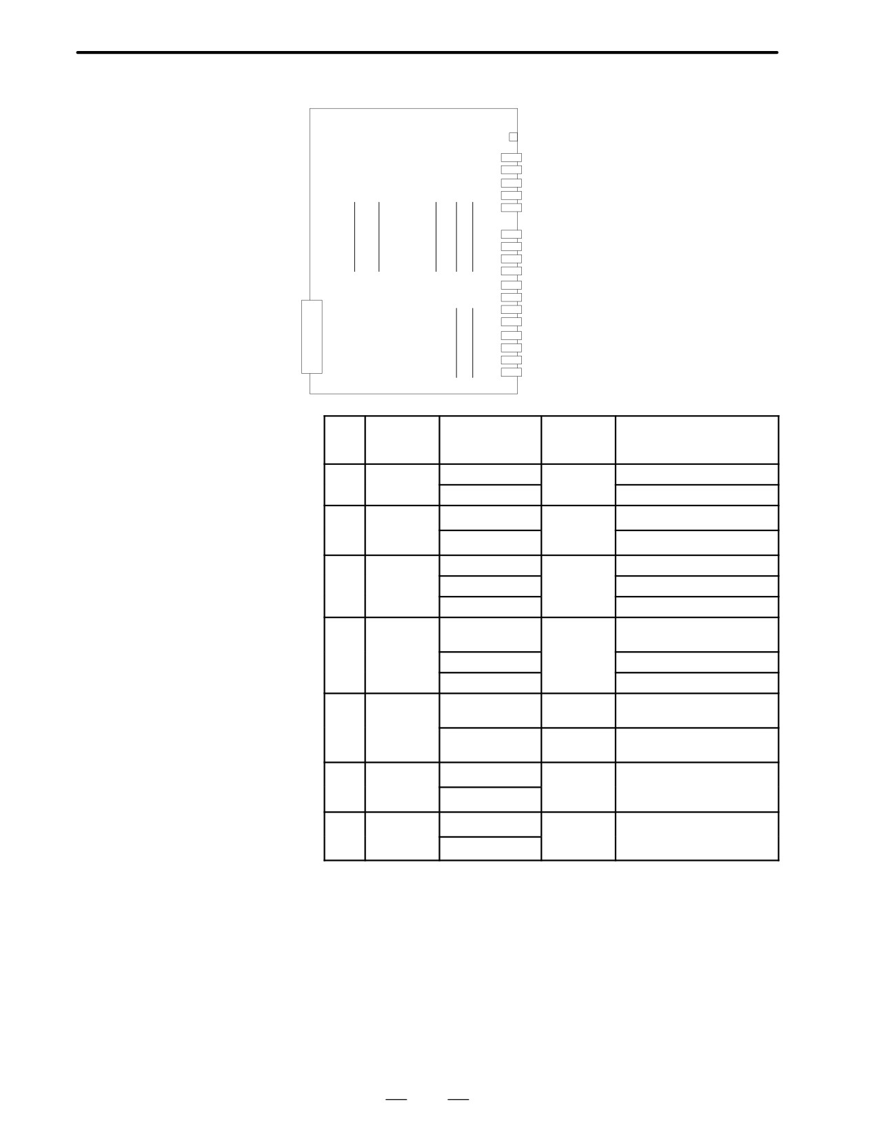
Connector Connector
A16B-2202-0400 and
name
number Use
A16B-2202-0401
LED
HDI
JA5
High-speed skip signal
A-1N
JA6
Analog input
SPDL-2
JA7B
Serial spindle
(1)
(2)
(3)
(4)
(5)
A-OUT2 JA8B
Analog output
APCBAT JA4B
Battery for use with the APC
AMP5
JV5
Axis 5 servo amplifier
AMP6
JV6
Axis 6 servo amplifier
AMP7
JV7
Axis 7 servo amplifier
AMP8
JV8
Axis 8 servo amplifier
ENC5
JF5
Axis 5 pulse coder
JNA
(6)
(7)
ENC6
JF6
Axis 6 pulse coder
ENC7
JF7
Axis 7 pulse coder
F-BUS
ENC8
JF8
Axis 8 pulse coder
SCALE5 JF25
Axis 5 scale
back plane
SCALE6 JF26
Axis 6 scale
connector
SCALE7 JF27
Axis 7 scale
SCALE8 JF28
Axis 8 scale
No.
Name
Specifications
Function
Display of system
configuration screen
(1)
FROM
A20B-2902-0081
2nd path
FLASH ROM MODULE:4MB
module
macro
A20B-2902-0082
FLASH ROM MODULE:2MB
(2)
SRAM
A20B-2900-0541
CNC
ADDITIONAL SRAM: 512KB
module
system
A20B-2901-0991
RAM
ADDITIONAL SRAM: 2MB
(3)
DRAM
A20B-2901-0940
CNC
DRAM:6MB
module
system
A20B-2901-0941
DRAM:4MB
RAM
A20B-2901-0942
DRAM:2MB
(4)
Spindle
A20B-2901-0984
Spindle
SERIAL SPINDLE LSI
module
control
ANALOG SPINDLE LSI
A20B-2901-0985
SERIAL SPINDLE LSI
A20B-2901-0986
ANALOG SPINDLE LSI
(5)
HAM
A20B-2900-0280
Analog
H-SKIP DI & ANALOG I/O:
module
I/O+HDI
HDI+ANALOG
A20B-2900-0281
HDI
H-SKIP DI & ANALOG I/O:
HDI
(6)
Servo
A20B-2902-0060
Servo con-
SERVO 7/8 AXIS
module
trol 7th or
A20B-2902-0061
8th axis
(7)
Servo
A20B-2902-0060
Servo con-
SERVO 5/6 AXIS
module
trol 5th or
A20B-2902-0061
6th axis
144