FANUC Series 0i-MODEL C, Series 0i Mate-MODEL C. MAINTENANCE MANUAL - page 7
2. HARDWARE
B-64115EN/02
2.3
TOTAL CONNECTION
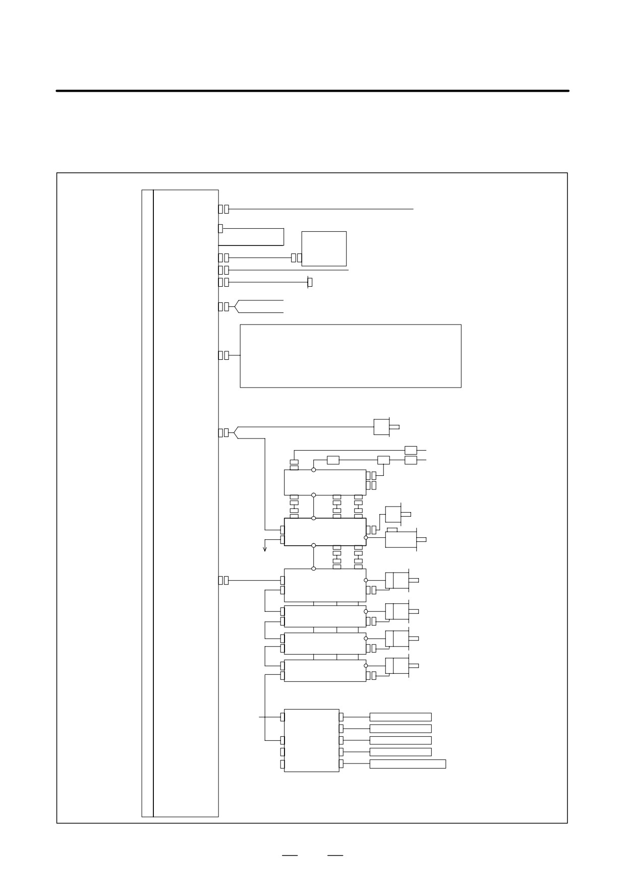
DIAGRAMS
Control unit
Main board
L
24V-IN(CP1A)
24 VDC power
C
(CN2)
MDI UNIT
D
Soft key cable
MDI(CA55)
CK1
R232(JD36A)
RS-232C I/O unit
R232(JD36B)
RS-232C I/O unit
Analog output for tool drive
A-OUT&HDI(JA40)
High-speed skip input
I/O Link(JD1A)
See I/O Link connection.
Position coder for analog spindle
SPDL&POS(JA7A)
Circuit breaker
AC reactor
200VAC
200VAC
MCC
Circuit breaker
CX3
CX1A TB2
PSM
CX4
CX1B TB1
JX1B
Position coder
CX1A TB1
CX2A JX1A
JA7B
SPM
JY2
TB2
JA7A TB1
CX2B JX1B
To 2nd spindle
Serial spindle motor
TB2
CX2A JX1A
FSSB(COP10A-1)
COP10B
TB2
Axis 1 servo motor
SVM
COP10A
JF1
TB1
CX2B JX1B
COP10B
Axis 2 servo motor
SVM
COP10A
COP10B
Axis 3 servo motor
SVM
COP10A
COP10B
Axis 4 servo motor
SVM
COP10A
The maximum allowable number of controlled axes varies with the model. (In this figure, a 1-axis
amplifier is used.)
Separate detector interface unit 1
24VDC
CP11A
JF101
Linear scale, axis 1
JF102
Linear scale, axis 2
COP10B
JF103
Linear scale, axis 3
COP10A JF104
Linear scale, axis 4
CNF1
JA4A
Absolute scale battery
(Required only when an absolute scale is used)
160
2. HARDWARE
B-64115EN/02
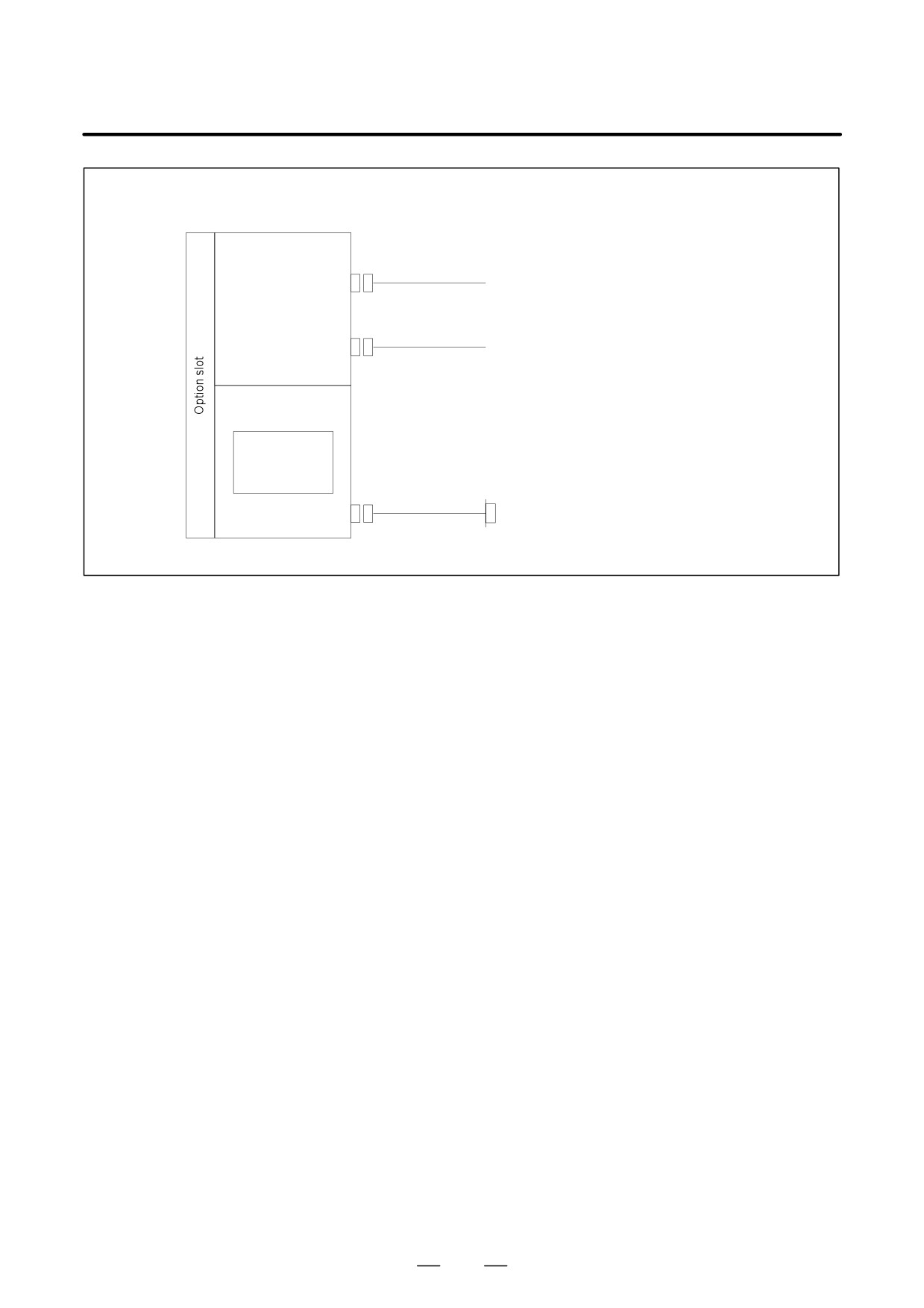
Control unit (Only when the Series 0i has an option function)
PROFIBUS board
Master JN1(CN1)
Slave JN2(CN2)
Data Server voard
Ethernet board
ATA flash card
(data server
port only)
100BASETx(CD38R)
Ethernet
161
2. HARDWARE
B-64115EN/02
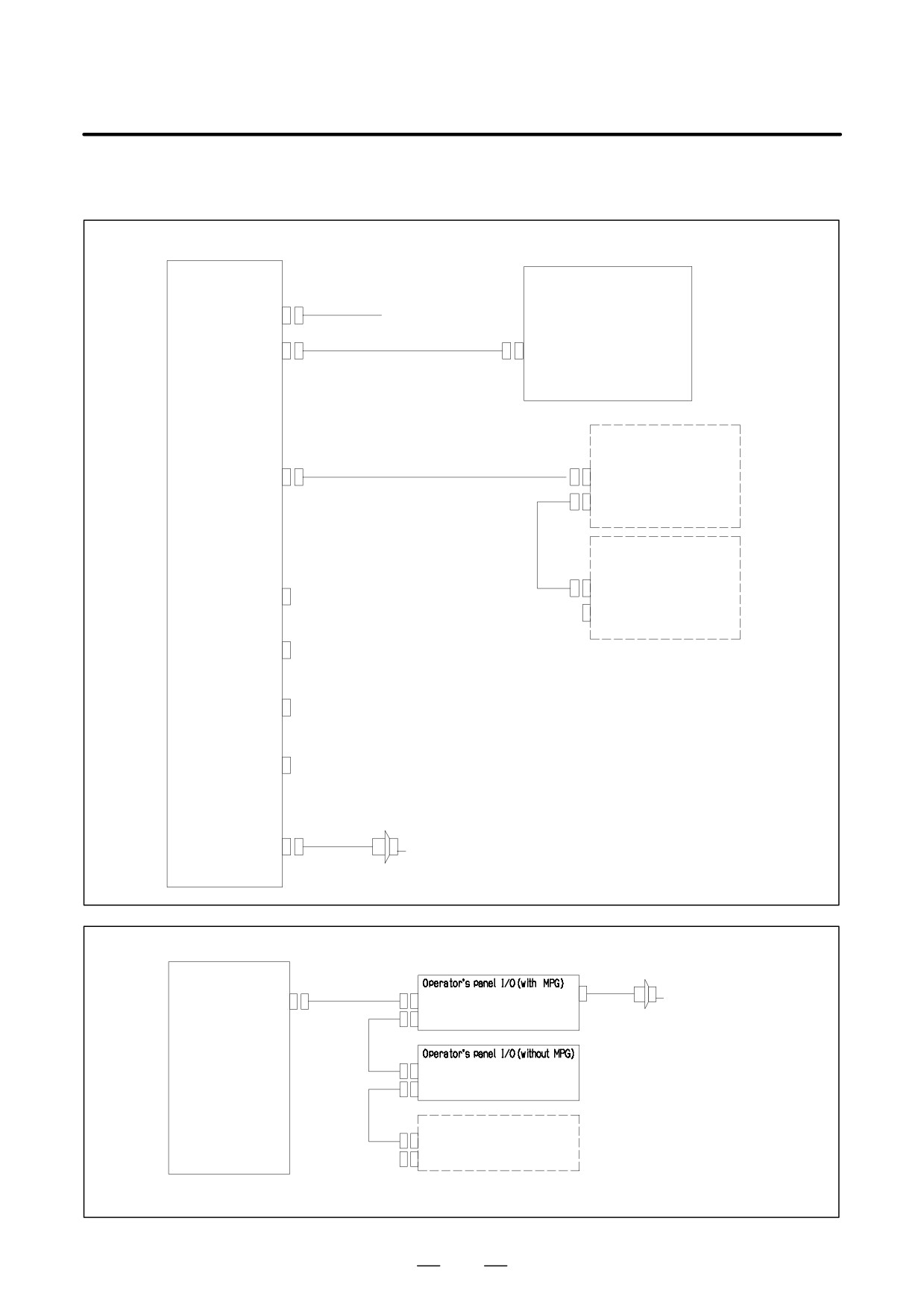
Sample I/O Link
connection
- For Series 0i
I/O unit for 0i
0i control unit
(CP1)
24VDC
I/O Link (JD1B)
JD1A
Operator’s panel I/O
I/O Link
I/O Link (JD1A)
JD1B
JD1A
DI : 96 points
DO : 64 points
I/O Link βi
servo amplifier
DI/DO-1
JD1B
(CB104)
JD1A
DI/DO-2
(CB105)
The order of slave devices connected
through I/O Link can be freely determined.
DI/DO-3
(CB106)
DI/DO-4
(CB107)
MPG(JA3)
Manual pulse generator (up to three)
– For Series 0i Mate
Main board
I/O Link
Manual pulse generator
I/O Link (JD1A)
JD1B
JA3
(up to three)
JD1A
JD1B
JD1A
I/O Link βi servo amplifier
(For the 0i Mate, only one servo amplifier
can be connected.)
The order of slave devices connected
through I/O Link can be freely determined.
162
2. HARDWARE
B-64115EN/02
2.4
CONNECTOR AND
CARD
CONFIGURATIONS
OF PRINTED CIRCUIT
BOARDS
2.4.1
Main Board
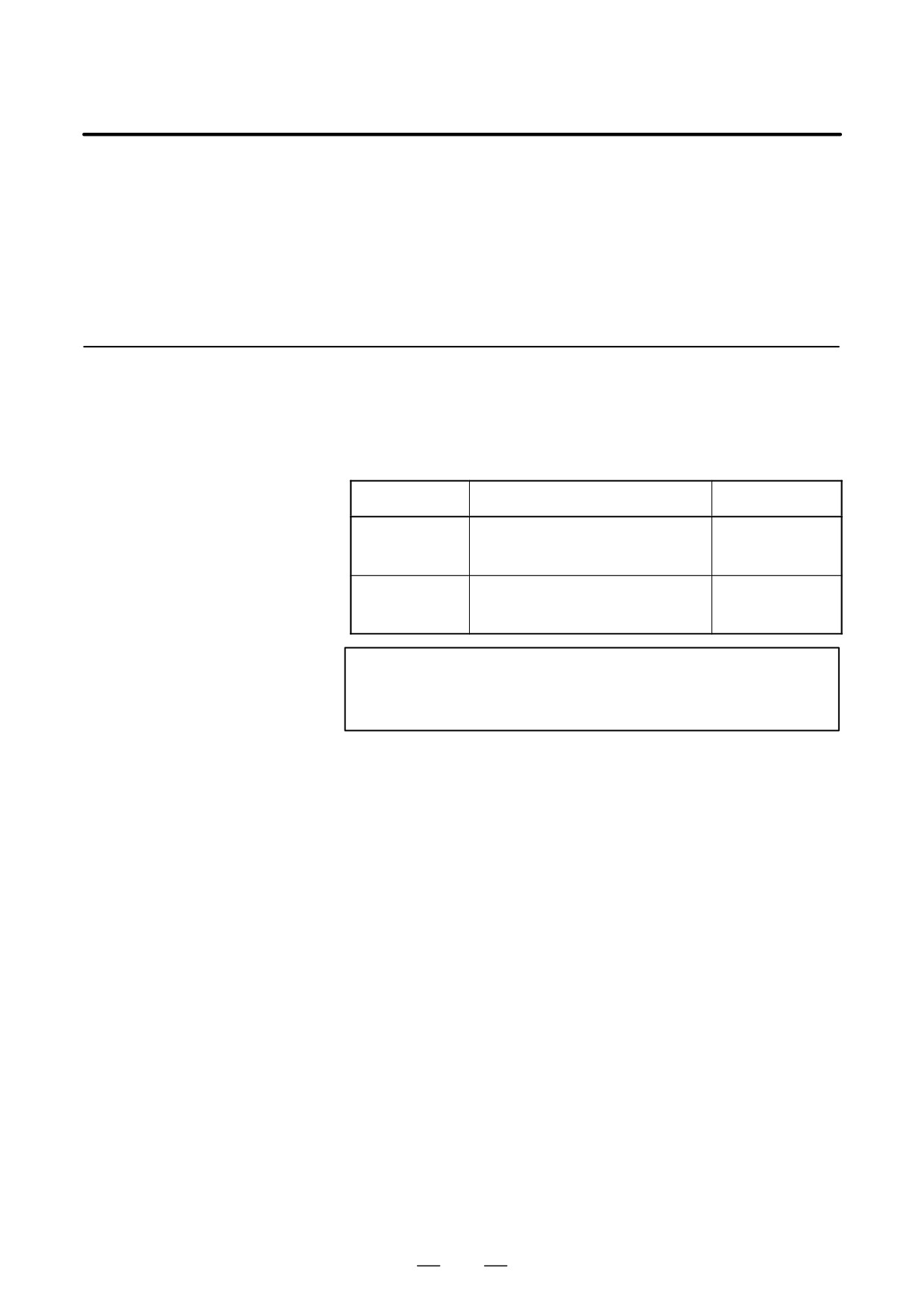
For the Series 0i/0i Mate-C, two types of basic unit are available. The
explanation differs depending on the drawing number of the basic unit.
Refer to the description on the appropriate page to refer to.
Model
Drawing number of the basic unit
Page to refer to
Series 0i -C
A02B-0309-B50n(n=0,1,⋅⋅⋅,9)
Page 164 to 169
Series 0i Mate-C
A02B-0311-B50n (n=0,1,⋅⋅⋅,9)
Series 0i Mate-C
A02B-0311-B51n (n=0,1,⋅⋅⋅,9)
Series 0i -C
A02B-0309-B52n(n=0,1,⋅⋅⋅,9)
Page 170 to 177
Series 0i Mate-C
A02B-0311-B52n (n=0,1,⋅⋅⋅,9)
Series 0i Mate-C
A02B-0311-B53n (n=0,1,⋅⋅⋅,9)
NOTE
For information on basic units, see page
2 of the
“Introduction” chapter.
163
2. HARDWARE
B-64115EN/02
D Specifications
Item
Code
Main board of Series 0i-C (for PMC-SA1)
A20B-8101-0280
Main board of Series 0i-C (for PMC-SB7)
A20B-8101-0281
Main board of Series 0i-Mate C
A20B-8101-0285
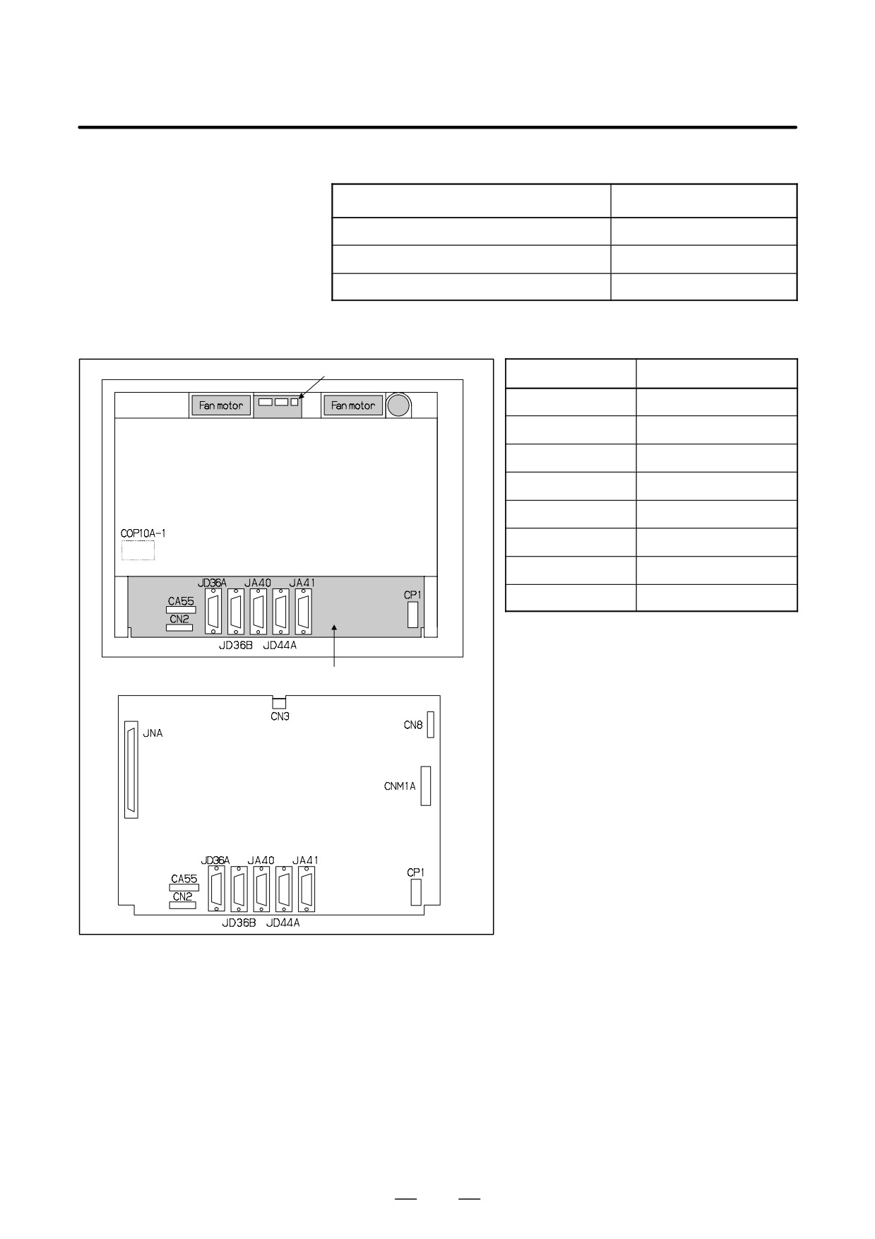
D Mounting positions of
connectors
Connector unit
Connector number
Application
COP10A-1
Servo interface (FSSB)
Battery
CA55
MDI
JD36A
RS-232C serial port
Rear of unit
JD36B
RS-232C serial port
JA40
Analog output/high-speed DI
JD44A
I/O link
(COP10A is a connector installed on the servo card.)
JA41
Serial spindle/position coder
CP1
24VDC-IN
Motherboard
Main board
164
2. HARDWARE
B-64115EN/02
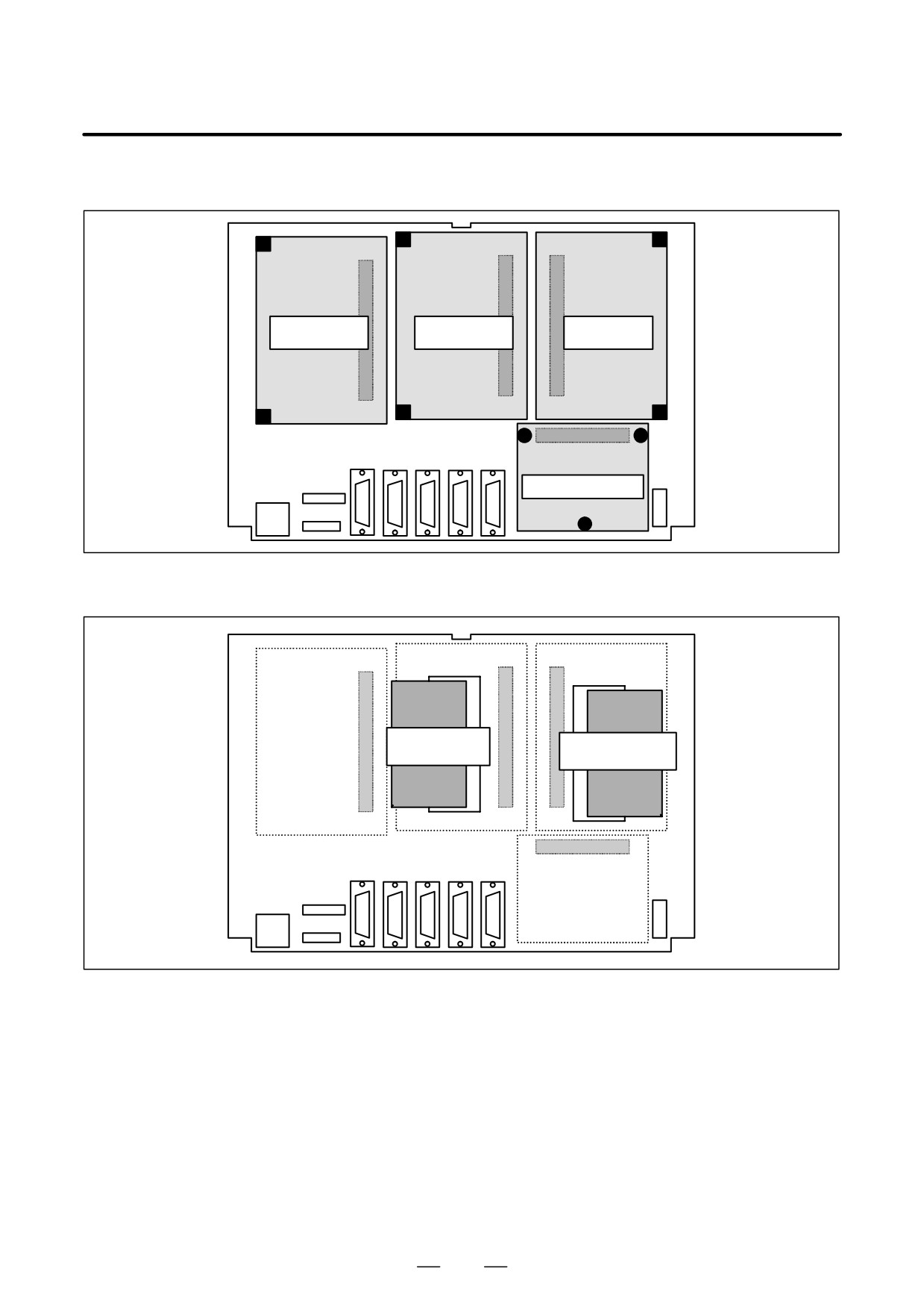
D Card and power supply
mounting location
Connector
Connector
Connector
(1) Axis control
(2) Display
(3) CPU card
card
control card
Connector
(4) Power supply unit
D DIMM module mounting
location
DIMM
module socket
(1) FROM/SRAM
(2) Analog spindle
module
module
DIMM
module socket
165
2. HARDWARE
B-64115EN/02
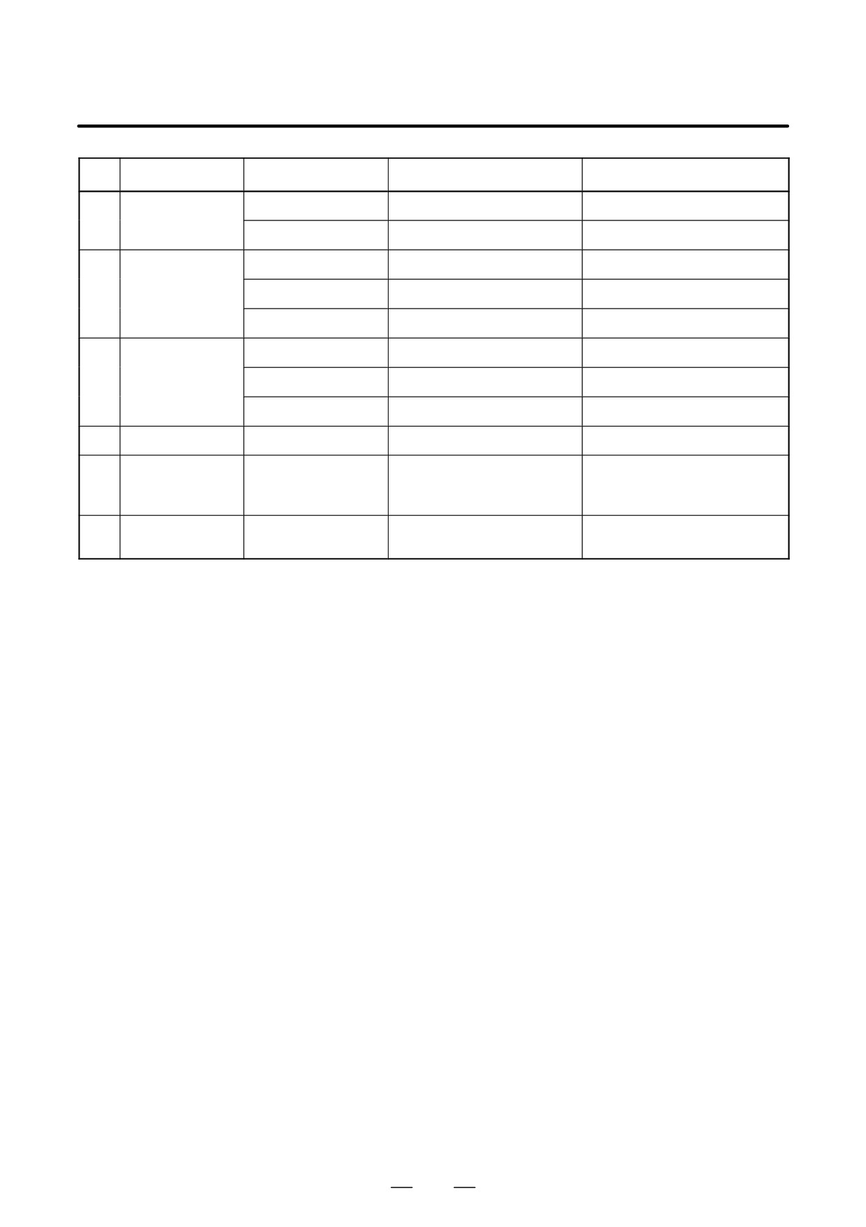
No.
Item
Code
Function
Remarks
(1)
Axis control card
A20B-3300-0393
Two axes control
A20B-3300-0392
Four axes control
(2)
Display control
A20B-3300-0280
10.4″ color LCD
card
A20B-3300-0281
8.4″ color LCD
A20B-3300-0283
7.2″ monochrome LCD
(3)
CPU card
A20B-3300-0291
DRAM 16MB 486
A20B-3300-0290
DRAM 32MB 486
0i-C only
A20B-3300-0313
DRAM 32MB Pentium
0i-C only
(4)
Power supply unit
A20B-8101-0180
(5)
FROM/SRAM
A20B-3900-0163
FROM 32MB
FROM stores various control
module
SRAM 1MB
software products. SRAM is
backed up by a battery.
(6)
Analog spindle
A20B-3900-0170
Analog spindle control position
module
coder interface
166
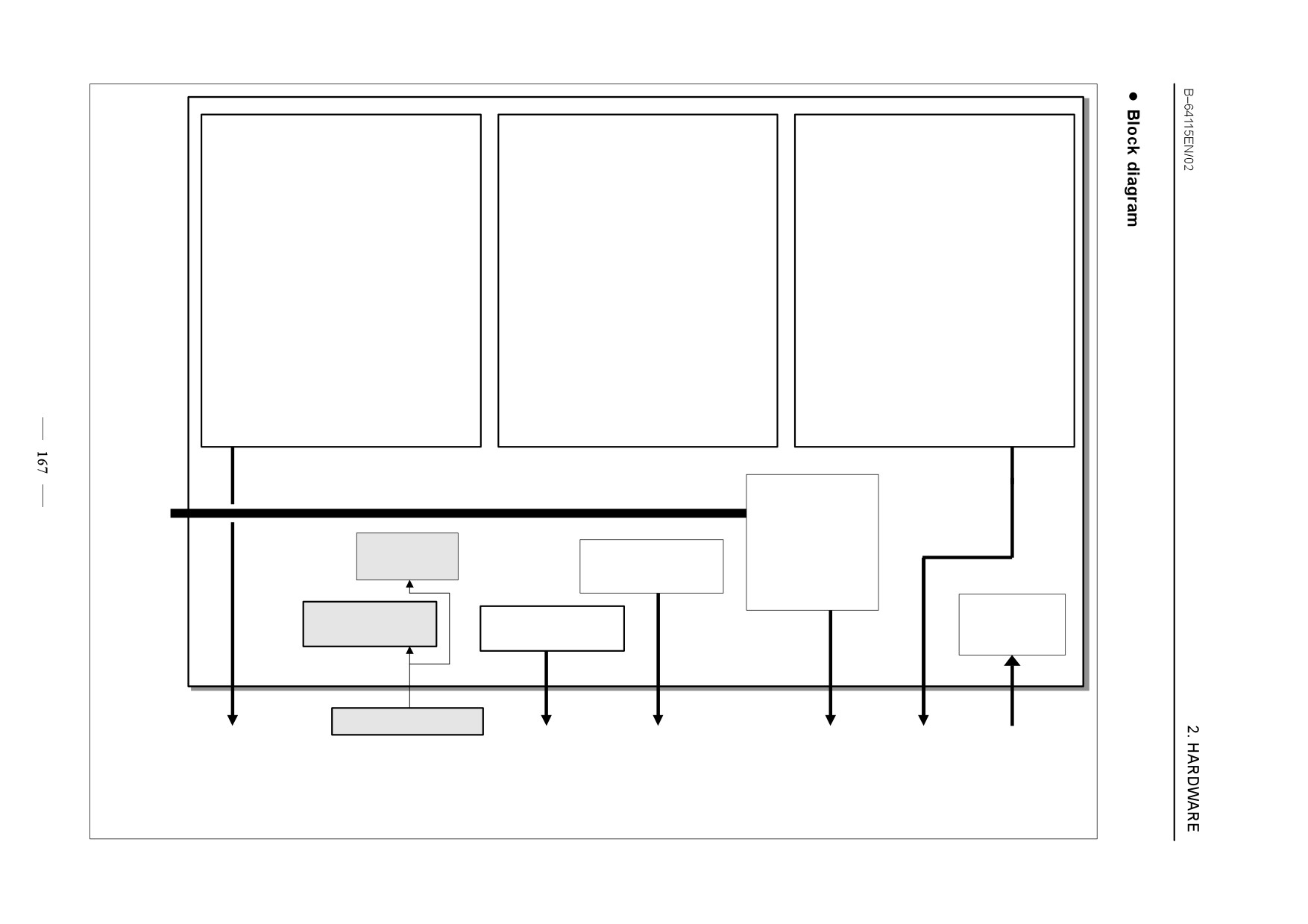
Axis control card
Display control card
CPU card
D
CPU for axis control
D
CPU for display control
D
CPU for CNC
D
Axis control circuit
D
Display control circuit
D Main memory (system soft ware)
D
Memory for display control
D
BOOT memory
D
Memory for axis control
D FSSB control circuit
F-BUS
PMC control circuit
(To back
Memory for DI/DO
panel)
Calendar
I/O Link control
Peripheral interface
circuit
control circuit
circuit
Power supply
FROM/SRAM
Analog spindle
unit
memory module
module
5V, 3.3V
Main board
3-V lithium battery
FSSB
Analog output
MDI interface
I/O LINK
RS-232-C
24VDC
(To servo amplifier)
Position coder
Memory card
interface
Serial spindle
High-speed DI
2. HARDWARE
B-64115EN/02
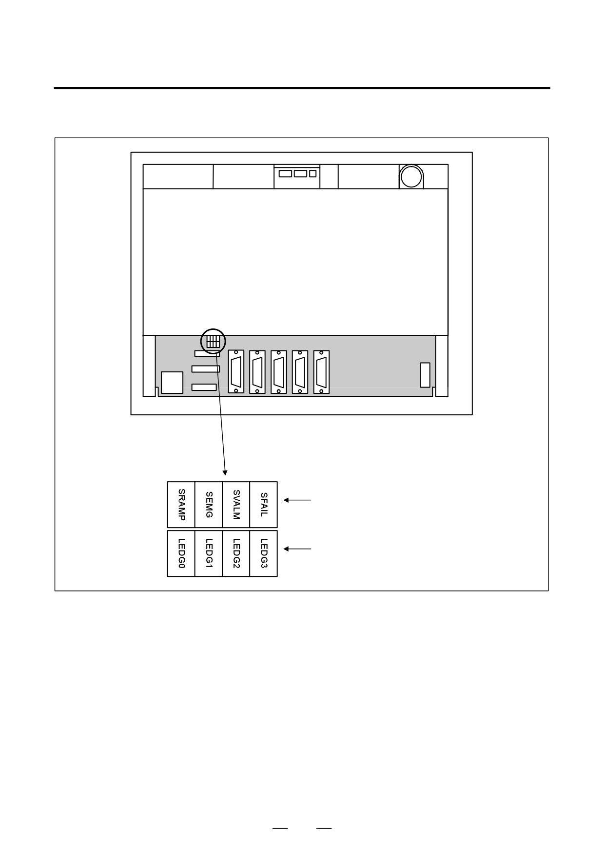
D LED display
Rear of unit
Alarm (red)
Status (green)
168
2. HARDWARE
B-64115EN/02
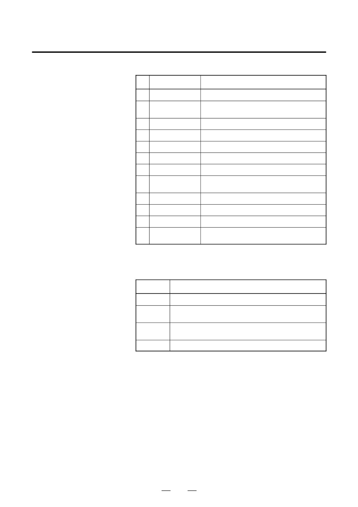
(1) Changes in status LED (green) indication at power-on time
No.
Status LED
Status
1
jjjj
Power is not supplied.
2
JJJJ
Initial status immediately after power is switched on; boot
is running.
3
jJJJ
System activation started.
4
JjJJ
Waiting for each processor ID in the system to be set up.
5
jjJJ
Each processor ID in the system has been set up.
6
JJjJ
FANUC bus initialized.
7
jJjJ
PMC initialized.
8
JjjJ
Information about the hardware configuration of each
printed-circuit board in the system has been set up.
9
jjjJ
PMC ladder initialized.
10
jJJj
Waiting for digital servo to be initialized.
11
JJJj
Digital servo initialized.
12
Jjjj
Initialization is completed, and normal operation is in
progress.
J: On j: Off
(2) Alarm LED (red) indication at system alarm occurrence
If any of these LEDs lights, it is likely that the hardware is defective.
Alarm LED
Meaning
SVALM
Servo alarm.
SEMG
Lights when a system alarm occurs.
The hardware has detected a failure in the system.
SFAIL
Lights when a system alarm occurs.
Used by the software to stop the system. Lights while boot is under way.
SRAMP
RAM parity or ECC alarm.
169
2. HARDWARE
B-64115EN/02
Main Board
D Specifications
Item
Code
Main biard of Series 0i-C
A20B-8200-0380
(PMC-SA1 CPU: Pentium DRAM: 32MB)
Main board of Series 0i-C
A20B-8200-0381
(PMC-SB7 CPU: Pentium DRAM: 32MB)
Main board of Series 0i-C
A20B-8200-0391
(PMC-SB7 CPU: 486 DRAM: 32MB)
Main board of Series 0i-C
A20B-8200-0390
(PMC-SA1 CPU: 486 DRAM: 32MB)
Main board of Series 0i-Mate C
A20B-8200-0395
(PMC-SA1 CPU: 486 DRAM: 16MB)
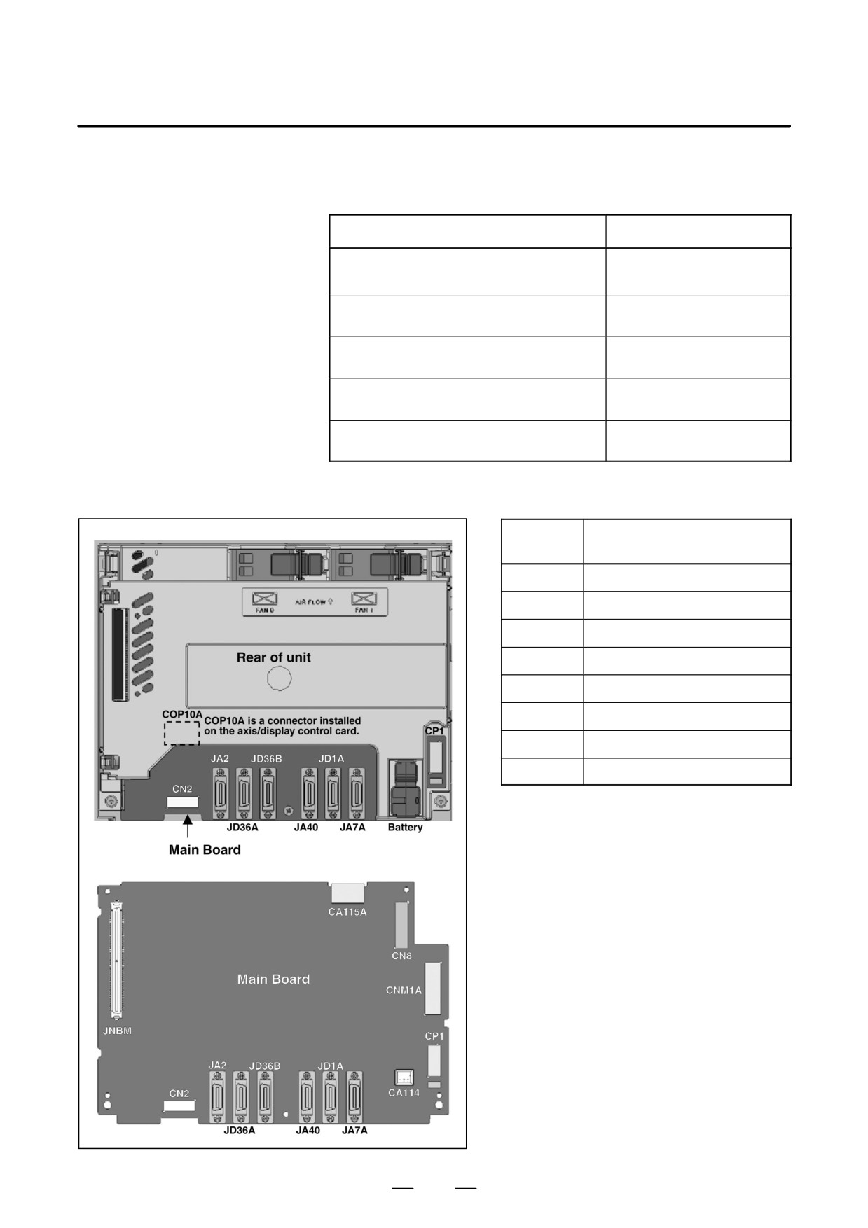
D Mounting positions of
connectors
Fan motor
Fan motor
Connector
Application
number
COP10A
Servo interface (FSSB)
JA2
MDI
JD36A
RS-232C serial port
JD36B
RS-232C serial port
JA40
Analog output/high-speed DI
JD1A
I/O link
JA7A
Serial spindle/position coder
CP1
Input power supply DC24V-IN
170
2. HARDWARE
B-64115EN/02
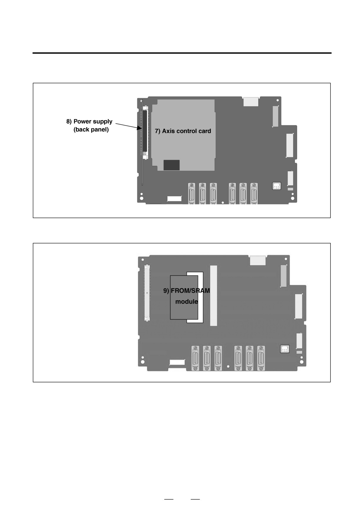
D Card and power supply
mounting location
D DIMM module mounting
location
171
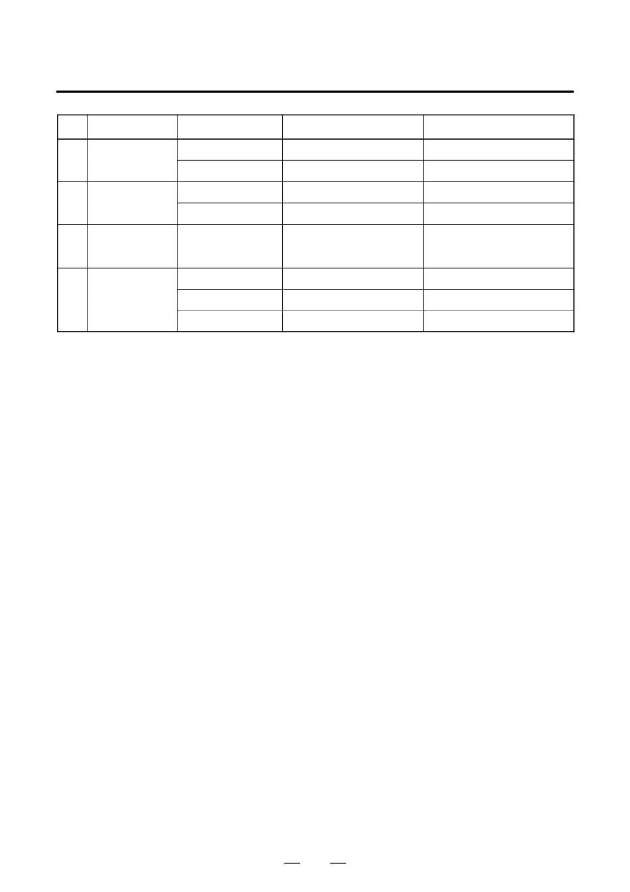
2. HARDWARE
B-64115EN/02
No.
Item
Code
Function
Remarks
(7)
Axis control card
A20B-8200-0360
Two axes control
A20B-8200-0361
Four axes control
(8)
Power supply card
A20B-8101-0430
For non slot
(back panel)
A20B-8101-0440
For two slots
0i-C only
(9)
FROM/SRAM
A20B-3900-0163
FROM: 32MB
FROM stores various control
module
SRAM: 1MB
software products. SRAM is
backed up by a battery.
(10)
Inverter
A20B-8002-0631
For 7.2″ monochrome LCD
A20B-8002-0632
For 10.4″ color LCD
A20B-8002-0633
For 8.4″ color LCD
172
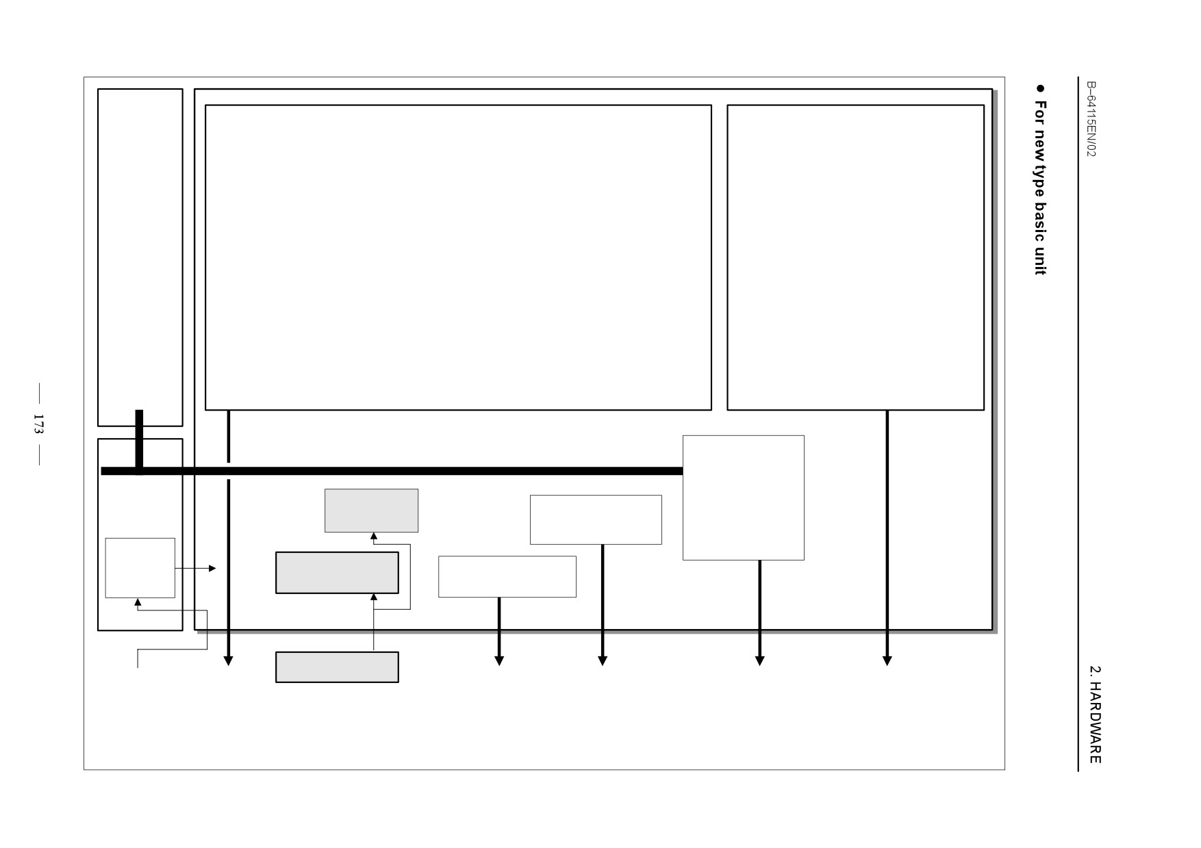
Axis control card
CPU card
Optional
board
D
CPU for axis control
D
CPU for display control
D
CPU for CNC
D
Axis control circuit
D
Display control circuit
D Main memory (system soft ware)
D
Memory for axis control
D
Memory for display control
D
BOOT memory
D FSSB control circuit
PMC control circuit
Memory for DI/DO
Power supply
(back panel)
Calendar
I/O Link control
Peripheral interface
circuit
control circuit
circuit
Power
supply
FROM/SRAM
circuit
Analog spindle
memory module
module
5V, 33V
Main board
3V litium battery
24VDC
FSSB
Analog output
MDI interface
I/O LINK
RS-232-C
Position coder
Memory card
(To servo amplifier)
interface
Serial spindle
High-speed DI
2. HARDWARE
B-64115EN/02
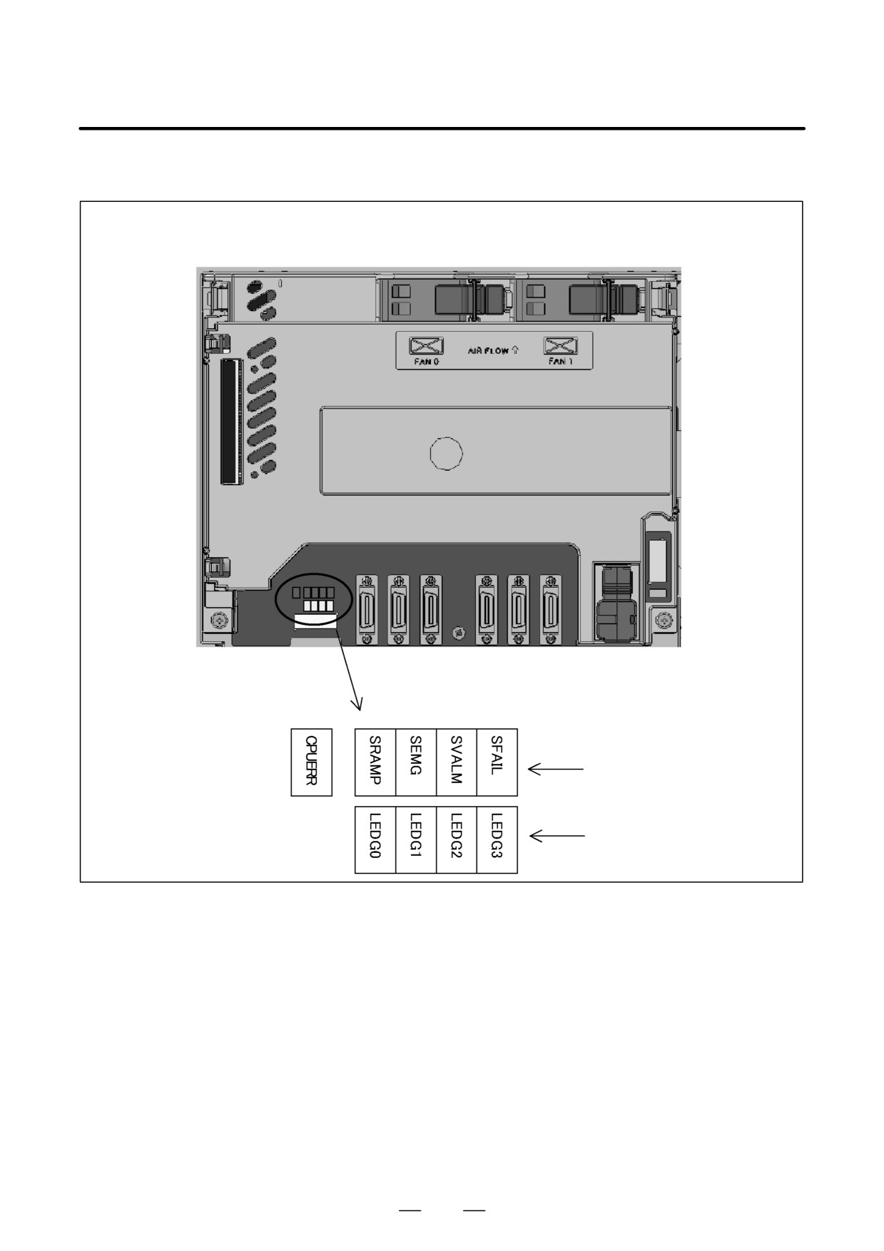
D LED display
For main board of A20B-8200-0380 or A20B-8200-0381
Alarm (red)
Status (green)
174
2. HARDWARE
B-64115EN/02
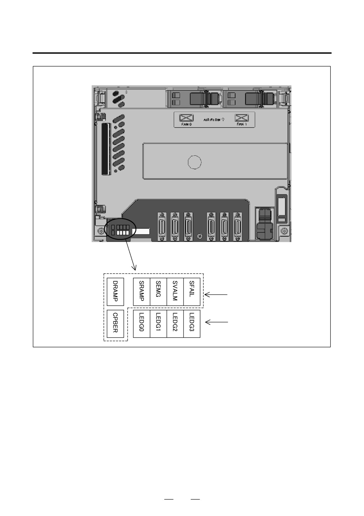
For main board of A20B-8200-0390, A20B-8200-0391, or A20B-8200-0395
Alarm (red)
Status (green)
175
2. HARDWARE
B-64115EN/02
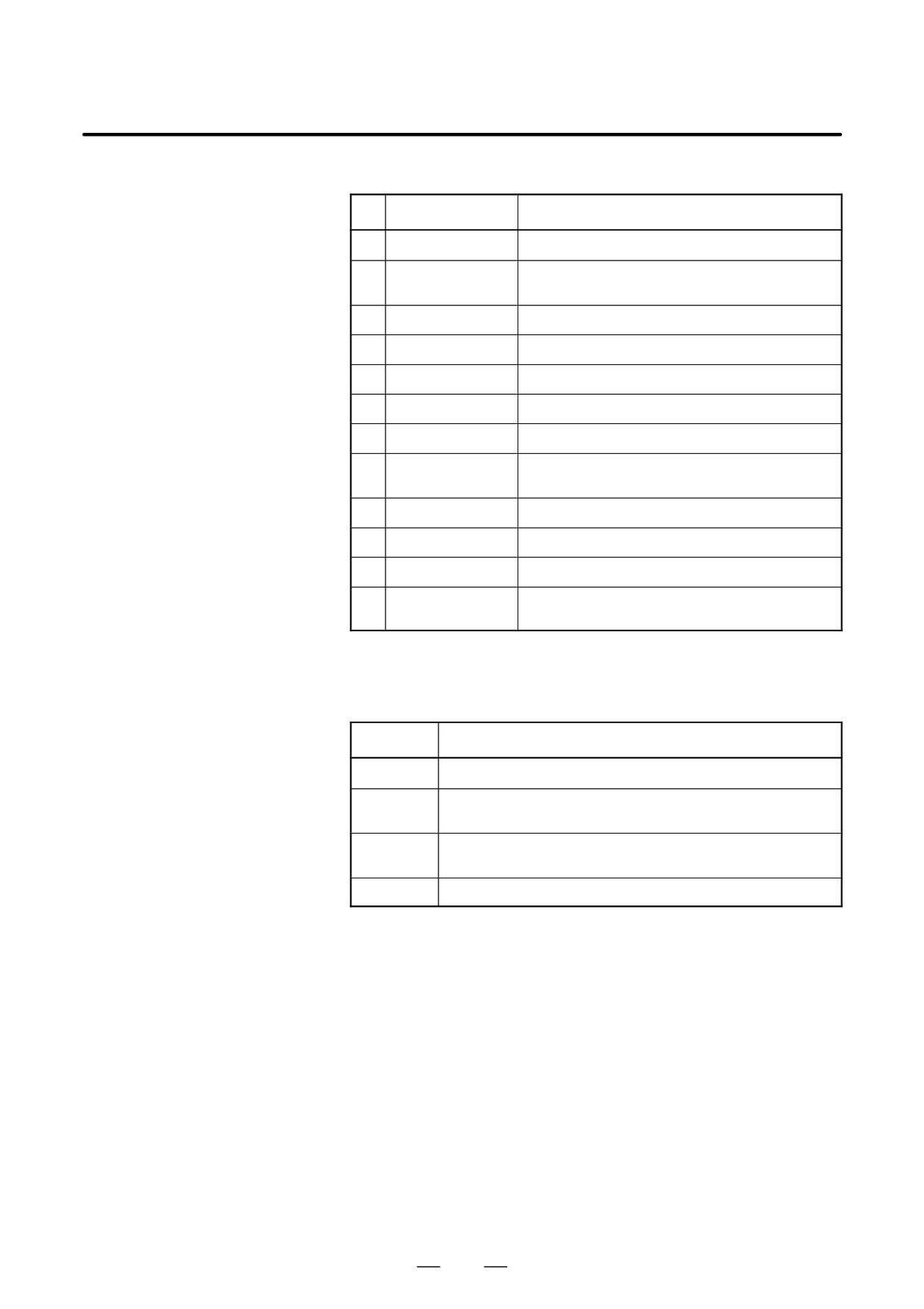
(1) Changes in status LED (green) indication at power-on time
No.
Status LED
Status
1
jjjj
Power is not supplied.
2
JJJJ
Initial status immediately after power is switched on; boot
is running.
3
jJJJ
System activation started.
4
JjJJ
Waiting for each processor ID in the system to be set up.
5
jjJJ
Each processor ID in the system has been set up.
6
JJjJ
FANUC bus initialized.
7
jJjJ
PMC initialized.
8
JjjJ
Information about the hardware configuration of each
printed-circuit board in the system has been set up.
9
jjjJ
PMC ladder initialized.
10
jJJj
Waiting for digital servo to be initialized.
11
JJJj
Digital servo initialized.
12
Jjjj
Initialization is completed, and normal operation is in
progress.
J: On j: Off
(2) Alarm LED (red) indication at system alarm occurrence
If any of these LEDs lights, it is likely that the hardware is defective.
Alarm LED
Meaning
SVALM
Servo alarm.
SEMG
Lights when a system alarm occurs.
The hardware has detected a failure in the system.
SFAIL
Lights when a system alarm occurs.
Used by the software to stop the system. Lights while boot is under way.
SRAMP
RAM parity or ECC alarm.
176
2. HARDWARE
B-64115EN/02
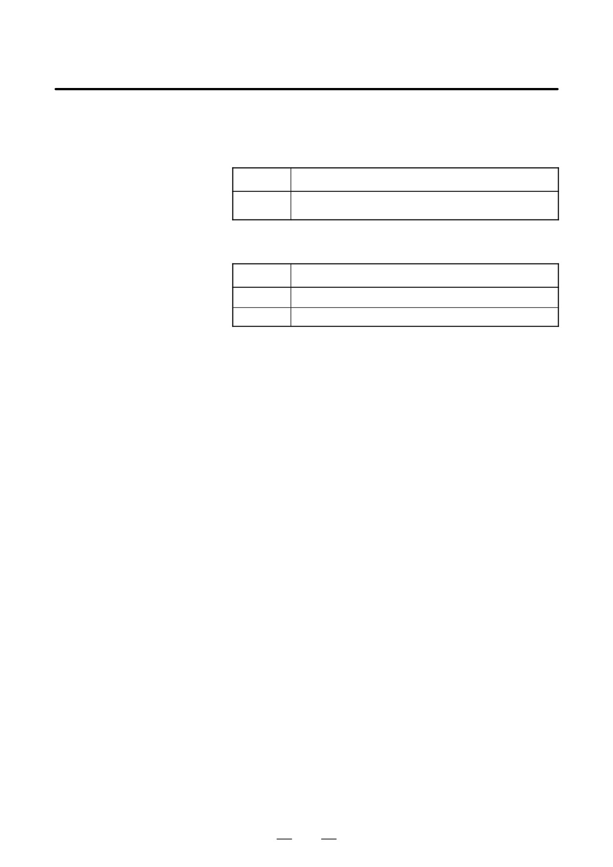
(3) Alarm LED (red) indication at system alarm occurrence
For A20B-8200-0380 or A20B-8200-0381
If this LED lights, it is likely that the hardware is defective.
Alarm LED
Meaning
CPUERR
When the LED lights: A DRAM parity alarm has been detected.
When the LED blinks: A bus error has been detected.
For A20B-8200-0390, A20B-8200-0391, or A20B-8200-0395
If any of these LED lights, it is likely that the hardware is defective.
Alarm LED
Meaning
DRAMP
A DRAM parity alarm has been detected.
CPUERR
A bus error has been detected.
177
2. HARDWARE
B-64115EN/02
2.4.2
Inverter PCBs
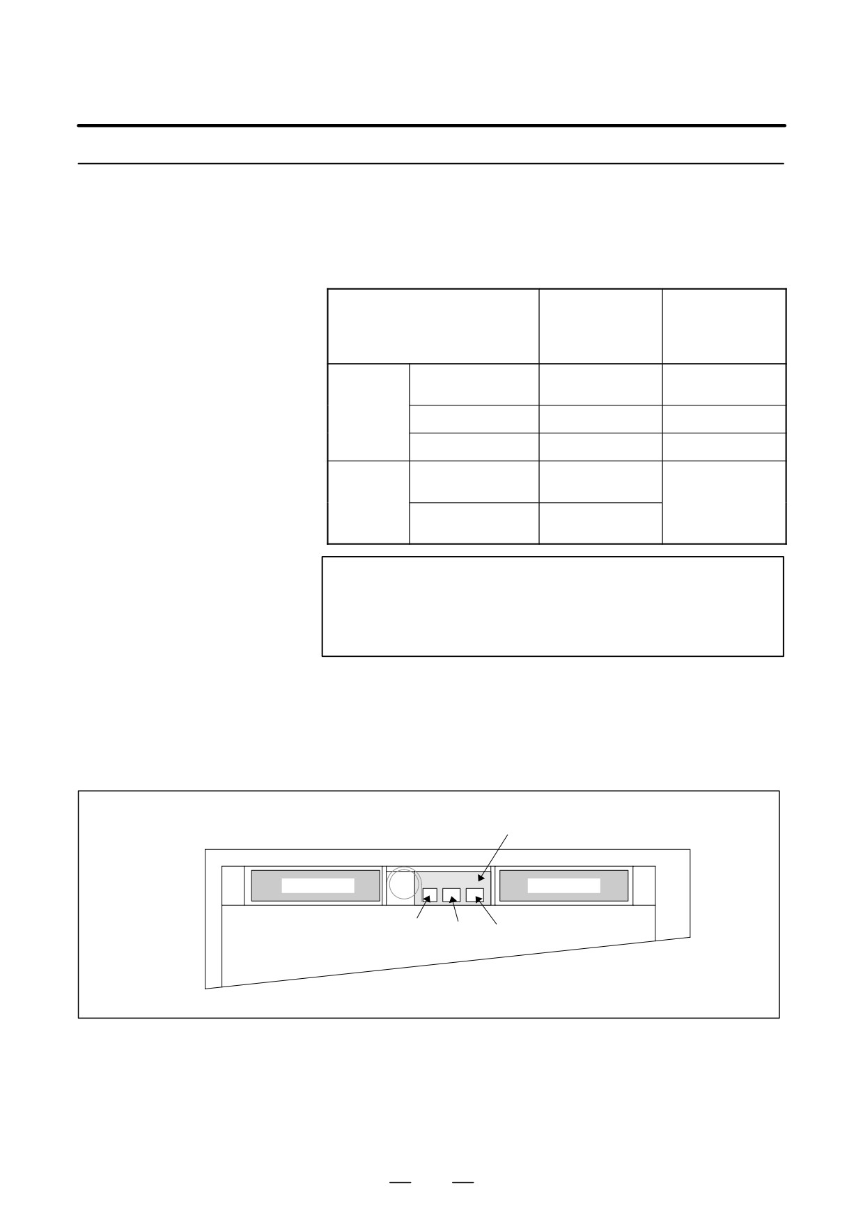
D Connector Units
For the Series 0i/0i Mate-C, two types of basic unit are available. The
explanation differs depending on the drawing number of the basic unit.
Drawing number of the basic
A02B-0309-B50n
A02B-0309-B52n
unit
A02B-0311-B50n
A02B-0311-B52n
A02B-0311-B51n
A02B-0311-B53n
(n=0,1,⋅⋅⋅,9)
(n=0,1,⋅⋅⋅,9)
Inverter
For 7.2″ monochrome
A20B-8100-0710
A20B-8002-0631
P.C.B
LCD
For 8.4″ color LCD
A20B-8001-0922
A20B-8002-0633
For 10.4″ color LCD
A20B-8001-0920
A20B-8002-0632
Connector
For unit with no option
A15L-0001-0060#B
Not existent.
unit
slot
For unit with two option
A15L-0001-0060#A
slots
NOTE
See Section 2.2, “HARDWARE OVERVIEW.”
The connector unit is fastened to the case with self-tapping
screws.
D Connector location
(For A20B-8100-0710,
A20B-8001-0922, and
A20B-8001-0920)
(1) With 2 slots
Connector unit
Fan motor
Fan motor
CP8
CN39A CN39B
(Battery)
(Fan)
(Fan)
Rear of unit
178
2. HARDWARE
B-64115EN/02
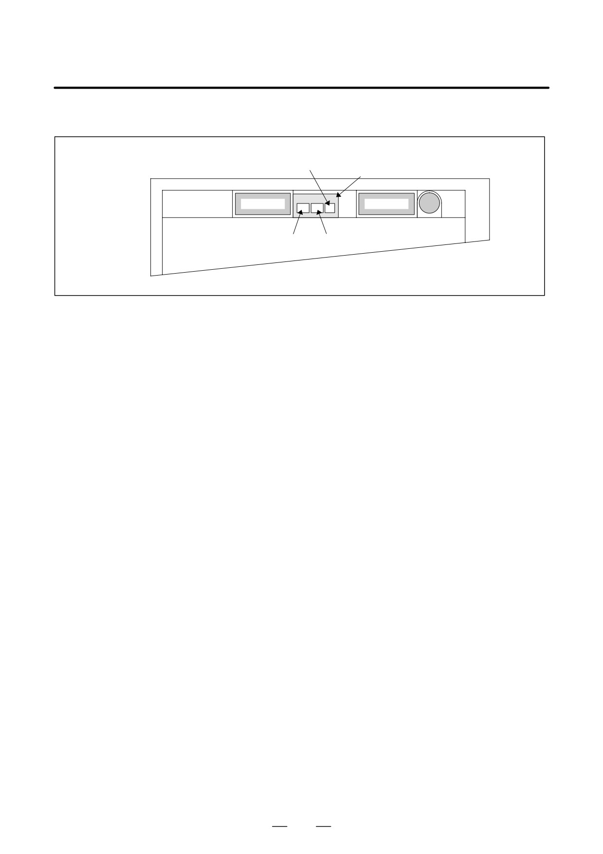
(2) With no slot
CP8
(Battery)
Connector unit
Fan motor
Fan motor
Battery
CN39A CN39B
(Fan)
(Fan)
Rear of unit
179
2. HARDWARE
B-64115EN/02
2.4.3
For the Series 0i-C, two types of basic unit are available.
The usable board differs depending on the basic unit.
Fast Ethernet Board
In this manual, boards are classified as “Fast Ethernet board A” and “Fast
Ethernet board B” for the sake of convenience.
Drawing number of the basic unit
Fast Ethernet board
A02B-0309-B50n (n=0,1,⋅⋅⋅,9)
Fast Ethernet board A
A02B-0309-B52n(n=0,1,⋅⋅⋅,9)
Fast Ethernet board B
Fast Ethernet board A
Name
Specification
Fast ethernet board
A20B-8100-0770
NOTE
The Ethernet board cannot fit into the option slot nearest to
the LCD.
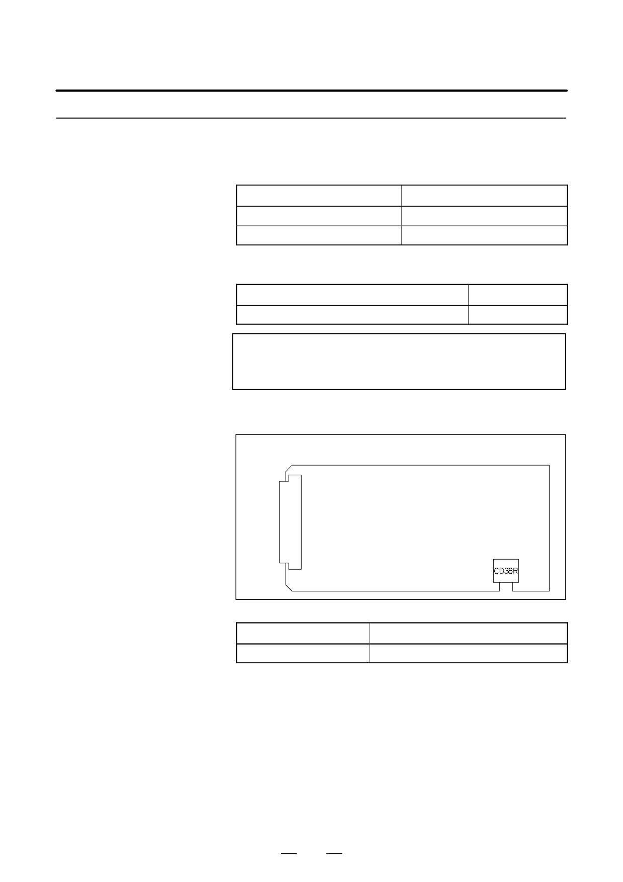
D Connector location
JNA
F-BUS backplane connector
Connector number
Application
CD38R
100BASE-TX Ethernet interface
D Card location
No card is mounted on the Ethernet board.
180
2. HARDWARE
B-64115EN/02
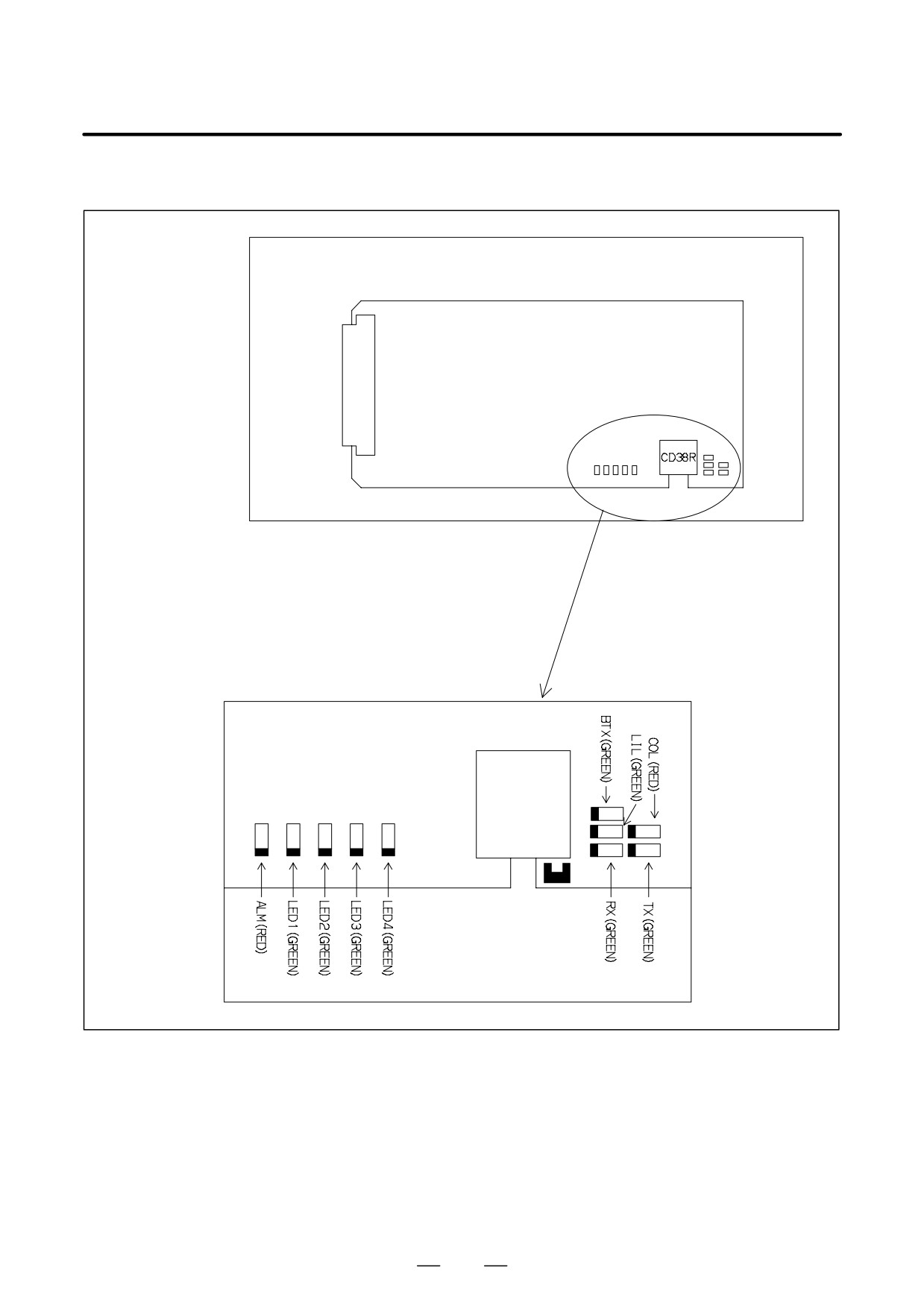
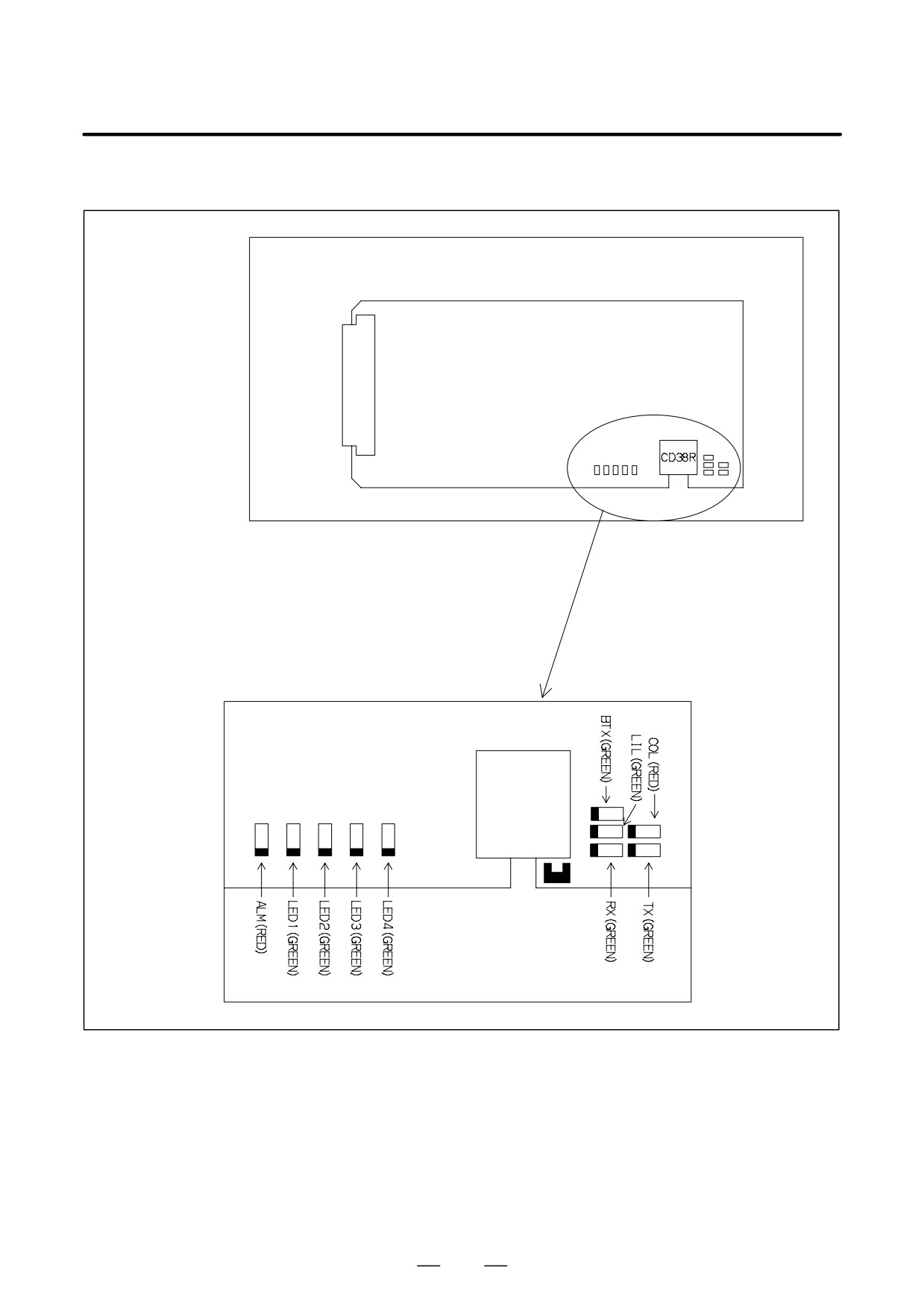
D LED indication
JNA
F-BUS backplane connector
Detailed LED diagram
CD38R
181
2. HARDWARE
B-64115EN/02
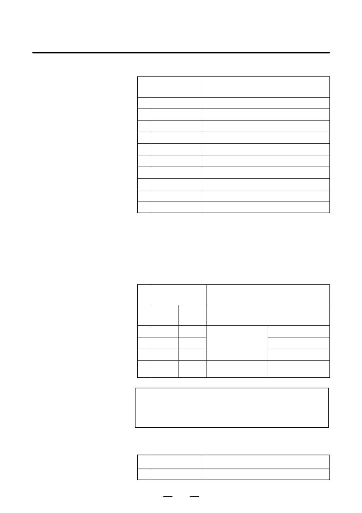
D LED indication transition at power-on time
LED indication
No.
Ethernet board status
1234
1
STATUS jjjj
Power off
2
STATUS JJJJ
Initial status immediately after power is switched on.
3
STATUS jJJJ
MPU initialization completed.
4
STATUS jjJJ
Firmware download completed.
5
STATUS jjjJ
Control passed to the OS.
6
STATUS JJJj
OS PHASE 1
7
STATUS jJJj
OS PHASE 2
8
STATUS JjJj
OS PHASE 3
9
STATUS jjJj
OS PHASE 4
10
STATUS ljjj
Start sequence completed.
When the Ethernet board is started normally, the STATUS LEDs light as
shown at No. 10. This condition is preserved unless an abnormal
condition occurs.
D STATUS LED indications if an error occurs
If an error occurs, the STATUS LEDs repeatedly flash “LONG” then
“SHORT.” (For “LONG,” the LED lights for a long time. For
“SHORT,” the LED lights for a short time.)
STATUS LED
indication
No.
Board state
LONG
SHORT
1234
4321
1
jjJJ
JJjj
Failure caused by this
SRAM parity alarm
board.
2
jJjJ
jjjj
General invalid instruction
3
jJjJ
Jjjj
Invalid slot instruction
4
jjJJ
Jjjj
Failure caused by another
NMI of another module
board.
NOTE
If an error, indicated by repeatedly flashing a LONG and
SHORT combination other than the above, occurs, contact
FANUC.
D ALARM LED indications if an error occurs
No.
LED indication
Board state
1
ALM
J
Parity error occurred in memory.
182
2. HARDWARE
B-64115EN/02
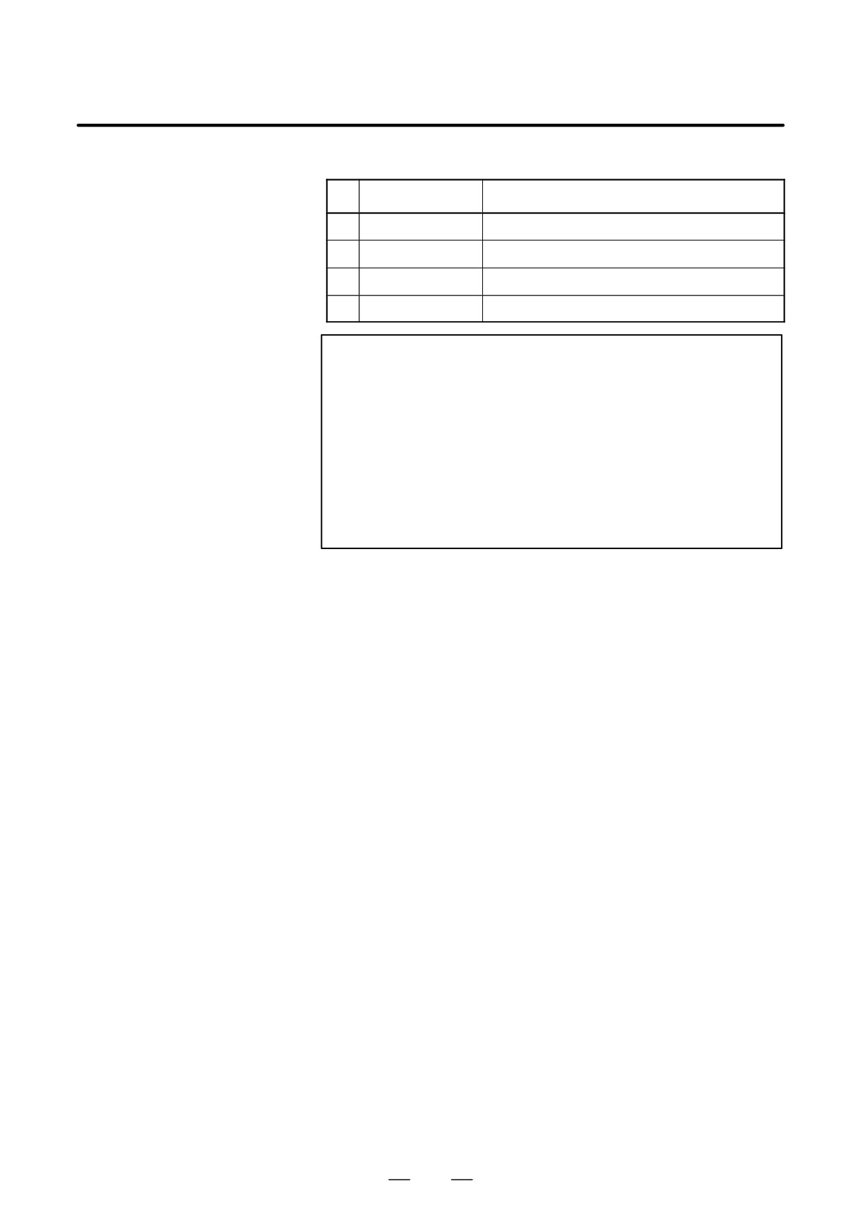
D LED indications related to communication status
No.
LED indication
Board state
1
RX/TX
J
Lights when data is received or sent.
3
LIL
J
Lights when the board is successfully connected to the hub.
4
COL
J
Lights if a data collision occurs.
5
BTX
J
Lights when a connection is made with 100BASE-TX.
NOTE
LIL:
Communication is not performed while this LED
is not lit. A probable reason for this is that the
board is not properly connected to the hub, or
that the hub is off. This LED should be lit at all
times while the board is properly connected to
the hub.
COL:
This LED lights frequently if there is excessive
traffic on the communication line or if there is
excessive peripheral electrical noise.
183
2. HARDWARE
B-64115EN/02
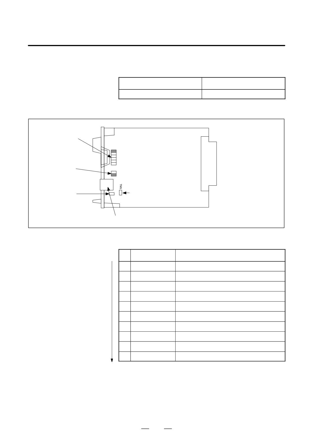
Fast Ethernet board B
D Specifications
Item
Code
Fast Ethernet board
A20B-8100-0670
D Mounting positions of
connectors, LEDs, etc.
ALM (red)
COM (greem)
LED4 (green)
LED3 (green)
LED2 (green)
JNA
LED1 (green)
F-BUS backplane
connector
LIL (green)
COL (red)
BTX (green)
Setting pins
CD38R: Ethrenet Interface
D LED lighting sequence at power on
j: Off J: On l: Blinking Z: Don’t care
No.
LED indication
Fast Ethernet board status
1
STATUS jjjj
Power off
2
STATUS JJJJ
Initial state after power on
3
STATUS JJJj
MPU initialized.
4
STATUS JJjj
Firmwaredownloaded.
5
STATUS Jjjj
Control migration to OS
6
STATUS jJJJ
OS PHASE1
7
STATUS jJJj
OS PHASE2
8
STATUS jJjJ
OS PHASE3
9
STATUS jJjj
OS PHASE4
10
STATUS jjjl
Startup completed.
The system enters No.10 status when the Fast Ethernet board starts up
normally. This status is maintained until an error occurs.
184
2. HARDWARE
B-64115EN/02
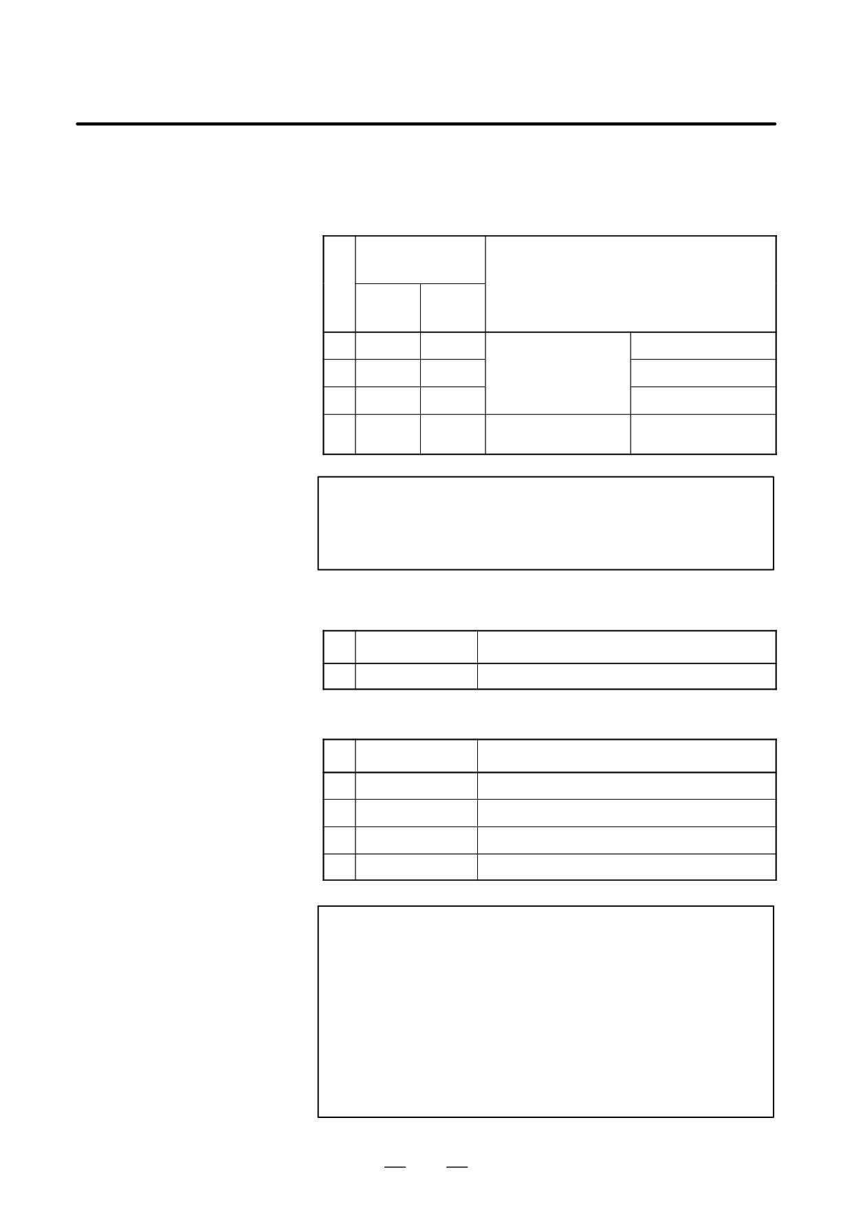
D STATUS LED indications if an error occurs
If an error occurs, the STATUS LEDs repeatedly flash “LONG” then
“SHORT.” (For “LONG,” the LED lights for a long time. For
“SHORT,” the LED lights for a short time.)
STATUS LED
indication
No.
Board state
LONG
SHORT
4321
4321
1
JJjj
jjJJ
Failure caused by this
SRAM parity alarm
board.
2
JjJj
jjjj
General invalid instruction
3
JjJj
jjjJ
Invalid slot instruction
4
JJjj
jjjJ
Failure caused by another
NMI of another module
board.
NOTE
If an error, indicated by repeatedly flashing a LONG and
SHORT combination other than the above, occurs, contact
FANUC.
D ALARM LED indications if an error occurs
No.
LED indication
Board state
1
ALM
J
Parity error occurred in memory.
D LED indications related to communication status
No.
LED indication
Board state
1
COM
J
Lights when data is received or sent.
3
LIL
J
Lights when the board is successfully connected to the hub.
4
COL
J
Lights if a data collision occurs.
5
BTX
J
Lights when a connection is made with 100BASE-TX.
NOTE
LIL:
Communication is not performed while this LED
is not lit. A probable reason for this is that the
board is not properly connected to the hub, or
that the hub is off. This LED should be lit at all
times while the board is properly connected to
the hub.
COL:
This LED lights frequently if there is excessive
traffic on the communication line or if there is
excessive peripheral electrical noise.
185

2. HARDWARE
B-64115EN/02
D Setting pins
On the board, the setting pins (T4, TM5) are installed. Connect jumper
plugs to side A (factory-set state). Do not remove a jumper plug, and do
not change the setting of a jumper plug. Otherwise, the board does not
operate normally.
186
2. HARDWARE
B-64115EN/02
2.4.4
For the Series 0i-C, two types of basic unit are available.
The usable board differs depending on the basic unit.
Fast Data Server Board
In this manual, boards are classified as “Fast Data Server board A” and
“Fast Data Server board B” for the sake of convenience.
Drawing number of the basic unit
Fast Data Server board
A02B-0309-B50n (n=0,1,⋅⋅⋅,9)
Fast Data Server board A
A02B-0309-B52n(n=0,1,⋅⋅⋅,9)
Fast Data Server board B
Fast Data Server board A
D Specification
Name
Specification
Fast data server board
A20B-8100-0770
(ATA card version)
Add-on board
A20B-2002-0960
NOTE
The data server board (ATA card version) cannot fit into any
of the following slots.
· Option slot nearest to the LCD
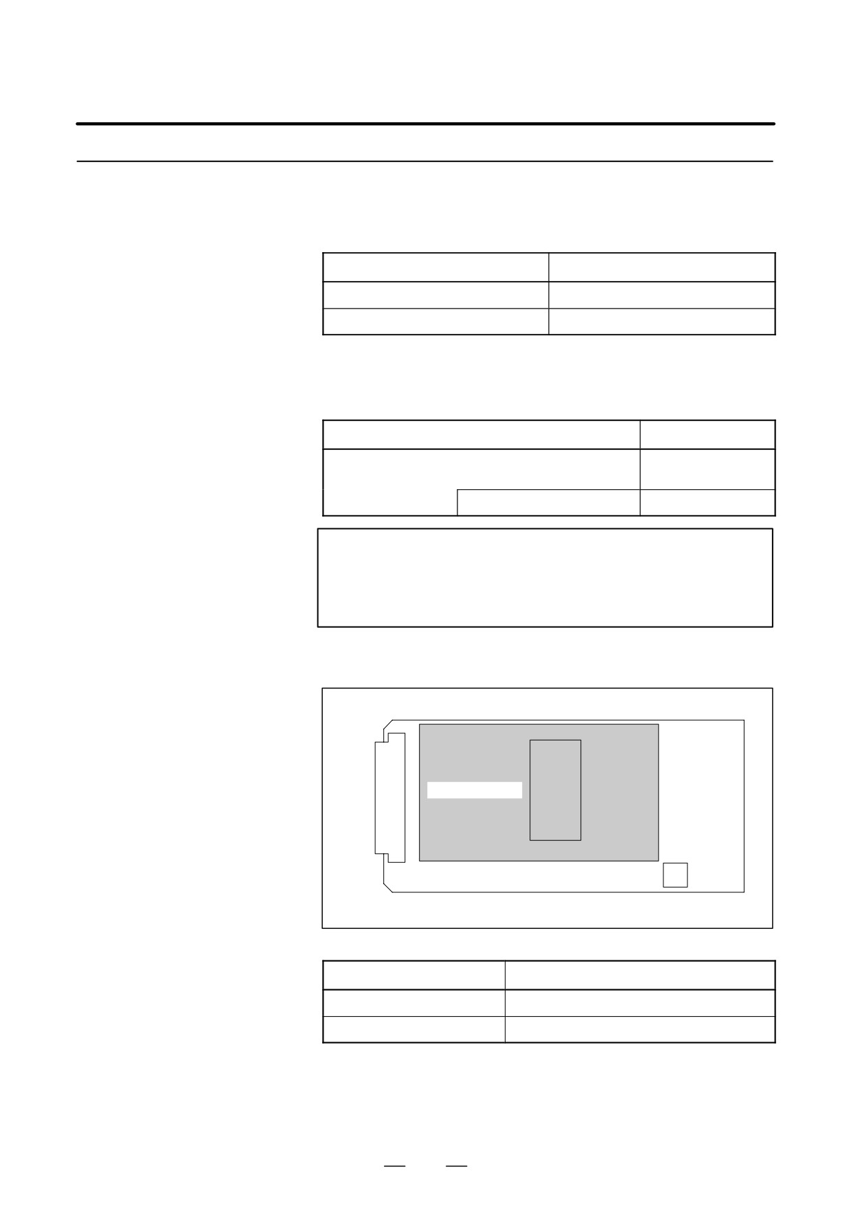
D Connector mounting
location
F-BUS backplane connector
JNA
Add-on board
CNH6
CR38R
CNH6 is mounted on the add-on board.
Connector number
Application
CNH6
ATA card interface
CD38R
100BASE-TX Ethernet interface
187
2. HARDWARE
B-64115EN/02
D LED indication
JNA
F-BUS backplane connector
Detailed LED diagram
CD38R
188
2. HARDWARE
B-64115EN/02
LED indication transition at power-on time
LED indication
No.
Board status
1234
1
STATUS jjjj
Power off.
2
STATUS JJJJ
Initial status immediately after power is switched on.
3
STATUS jJJJ
MPU initialization completed.
4
STATUS jjJJ
Firmware download completed.
5
STATUS jjjJ
Control passed to the OS.
6
STATUS JJJj
OS PHASE 1
7
STATUS jJJj
OS PHASE 2
8
STATUS JjJj
OS PHASE 3
9
STATUS jjJj
OS PHASE 4
10
STATUS ljjj
Start sequence completed.
When the Data Server board is started normally, the STATUS LEDs light
as shown at No. 10. This condition is preserved unless an abnormal
condition occurs.
189