FANUC Series 0i-MODEL C, Series 0i Mate-MODEL C. MAINTENANCE MANUAL - page 6
1. DISPLAY AND OPERATION
B-64115EN/02
When the Power Mate CNC series is used as an additional axis (slave) of
1.18
the CNC, the Power Mate CNC manager allows the slave data to be
POWER MATE CNC
displayed and set by the CNC.
MANAGER
The Power Mate CNC manager enables the following display and setting:
(1) Current position display (absolute/machine coordinates)
(2) Parameter display and setting
(3) Diagnosis display
(4) System configuration screen display
(5) Alarm display
The Power Mate CNC series that can be used as the slave is a β amplifier
with I/O Link.
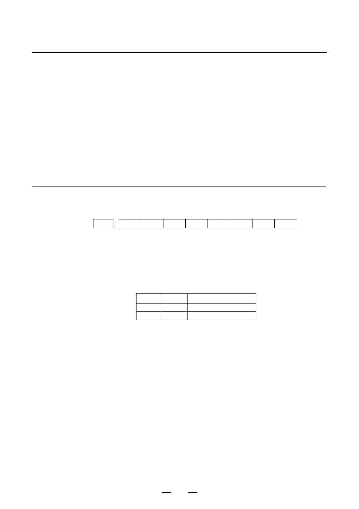
1.18.1
Parameter
#7
#6
#5
#4
#3
#2
#1
#0
960
2CH
ASG
SLPWE
PMN
MD2
MD1
SLV
[Data type]
Bit
SLV
When the Power Mate CNC manager is selected, the screen shows the
data of:
0 : A single slave.
1 : Up to four slaves by dividing the screen into four segments.
MD1, MD2
The slave parameters are input from and output to the following devices:
MD2
MD1
I/O device
0
0
Part program storage
0
1
Memory card
The parameters are input or output in the program format, no matter which
I/O device is selected.
PMN
The Power Mate CNC manager function is:
0 : Enabled.
1 : Disabled.
(Communication with the slave is not performed.)
SLPWE
The settings of slave parameters:
0 : Can be made by Power mate CNC manager regardless of the PWE
setting.
1 : Are made according to the PWE setting.
ASG
Whether or not the number of bytes allocated to the input/output
destination of the β amplifier with I/O links is 16:
0 : Is checked.
1 : Is not checked.
2CH
Power mate CNC manager:
0 : Communicates with channel 2.
1 : Communicates with channel 1.
130
B-64115EN/02
1. DISPLAY AND OPERATION
NOTE
1
The parameters are valid only when I/O link count extension
is supported (two channels are supported).
2
Even when
0 is set, Power Mate CNC Manager
communicates with channel 1 if the β amplifier with I/O links
is not connected to channel 2.
3
When 1 is set, Power Mate CNC Manager does not
communicate with channel 2 if the β amplifier with I/O links
is not connected to channel 1.
1.18.2
SYSTEM
1. Press the
function key.
Screen Display
2. Press the continuous menu key
several times. The [PMM] soft
key appears.
3. Press the [PMM] soft key. The system configuration screen, which is
the initial screen of the Power Mate CNC manager, appears. The
screen has the following soft keys (function selection soft keys).
[ POS
][
][
][SYSTEM][ MSG
]
The currently active soft key is displayed in reverse video. Pressing a soft
key enables the corresponding function, as indicated below:
POS: Current position display
SYSTEM: System information
MSG: Alarm list
To select another function after one of the functions listed above is
selected, press the return menu key
several times until the soft keys
are displayed as shown above. Then, select the desired function.
4. To terminate the Power Mate CNC manager, repeatedly press the
return menu key
until the function selection keys are displayed
as shown above. Then, press the return menu key once more. The
soft keys of the CNC system appear, and the Power Mate CNC
manager terminates. The system configuration screen of this function
is displayed as the termination screen.
Alternative termination method is to select another function while this
function is enabled. To do this, press an MDI function key (
POS
,
PROG
,
MESSAGE
, etc.).
NOTE
After another screen is displayed by pressing a function key,
SYSTEM
pressing the
function key, restores the initial status
of this function. That is, the soft keys shown above are
restored. The data that was being input is canceled.
131
1. DISPLAY AND OPERATION
B-64115EN/02
D System configuration
This screen displays the system software information of the slave. The
screen
screen is displayed first when the Power Mate CNC manager function is
selected. This screen is automatically displayed also at the termination
of the function.
1. Press the [SYSTEM] function selection soft key. The following soft
keys are displayed together with the screen displayed when SYSTEM
was last selected. The currently active soft key is displayed in reverse
video.
[ PARAM ][ DGNOS ][
][SYSTEM][
]
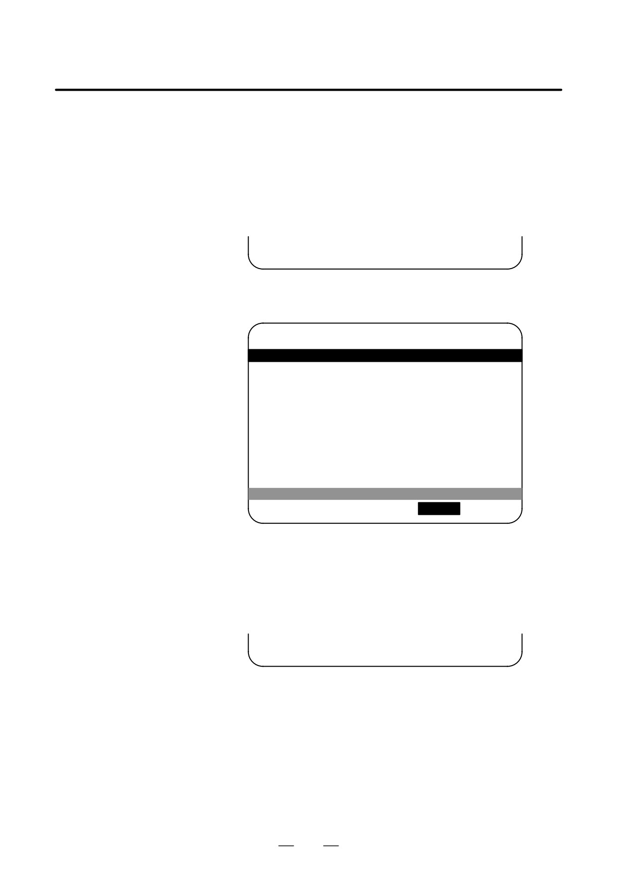
2. Press the [SYSTEM] soft key again. The system configuration screen
appears. While this screen is displayed, the [SYSTEM] soft key is left
displayed in reverse video.
POWER MOTION MANAGER
SYSTEM CONFIGURATION
1.GROUP0 / β
SYSTEM
<SERIES/VERSION>
88A1 01
[ PARAM ][ DGNOS ][
][ SYSTEM ][
]
Sample screen: Series and edition of the servo unit β series system list
D Parameter screen
The parameters necessary for the functions of the slave must be specified
in advance.
1. Press the [SYSTEM] function selection soft key. The following soft
keys appear.
[ PARAM ][ DGNOS ][
][SYSTEM][
]
132
B-64115EN/02
1. DISPLAY AND OPERATION
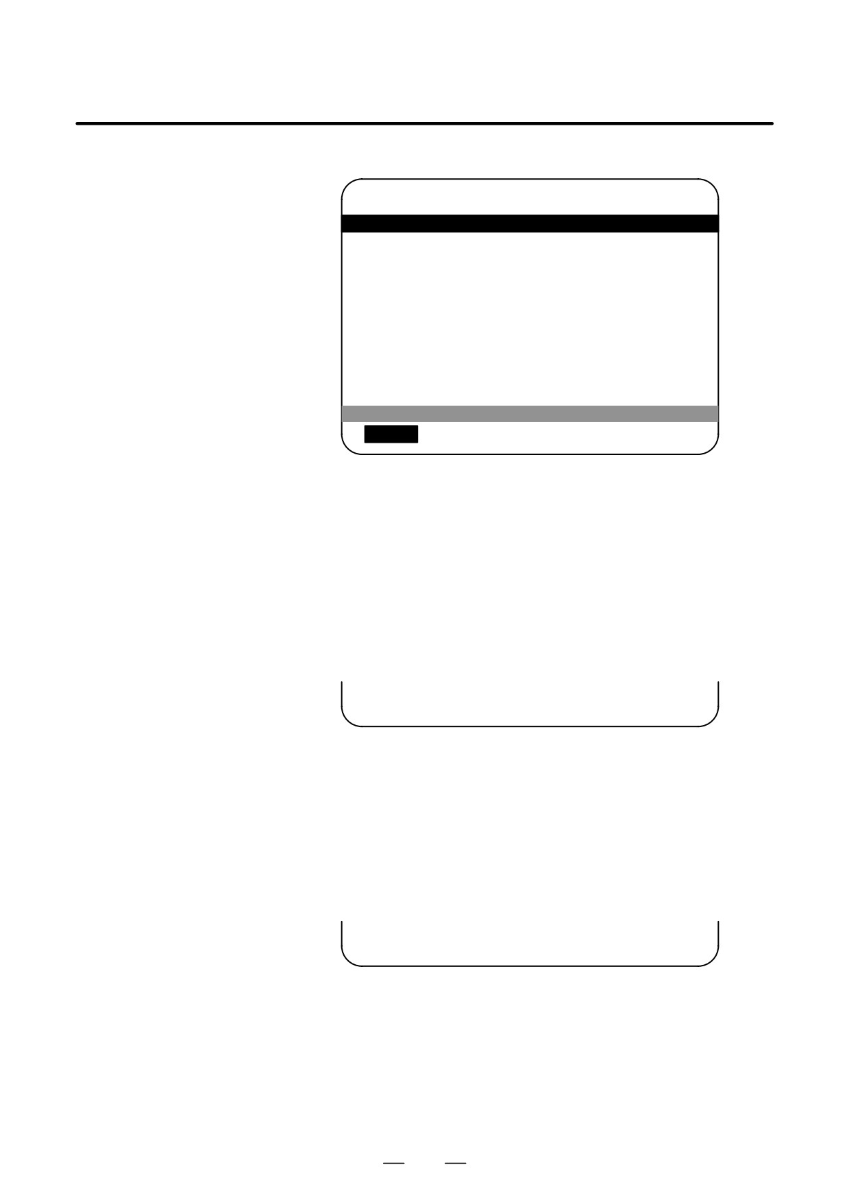
2. Press the [PARAM] soft key. The parameter screen appears.
POWER MOTION MANAGER
PARAMETER
1.GROUP0 / β
0000
00001000
0010
11110000
0001
00010101
0011
01010000
0002
11111011
0012
00000000
0003
00000000
0013
00000000
0004
00000000
0014
10110001
0005
10100001
0015
00000000
0006
00000000
0016
00000000
0007
10000000
0017
10000010
0008
00000000
0018
00000000
0009
00000000
0019
00000000
[
PARAM ][ DGNOS ][
][ SYSTEM ][
]
The screen displays just the bit and decimal data. For details of the
parameters, refer to the connection manual of the corresponding Power
Mate CNC unit.
D Searching for a parameter
A search can be made for the parameter to be displayed.
1. Select the active slave.
2. Press the [(OPRT)] soft key. The following soft keys appear.
[ NO.SRH ][
][
][
][ INPUT ]
3. Enter a desired number in the key-in field by using MDI numeric keys.
Then, press the [NO.SRH] soft key. The search starts.
D Setting a parameter
A parameter of a slave Power Mate CNC unit can be directly set from the
CNC.
1. Select the active slave.
2. Press the [(OPRT)] soft key. The following soft keys appear:
[ NO.SRH ][
][
][
][ INPUT ]
3. Move the cursor to the parameter to be set.
4. Enter desired data in the key-in buffer by using MDI numeric keys.
Then, press the [INPUT] soft key. Alternatively, press the MDI
INPUT key.
133
1. DISPLAY AND OPERATION
B-64115EN/02
D Diagnosis screen
This screen shows the current status of the slave.
1. Press the [SYSTEM] function selection soft key. The following soft
keys appear:
[ PARAM ][ DGNOS ][
][SYSTEM][
]
2. Press the [DGNOS] soft key. The diagnosis screen appears. The
displayed data is basically the same as the data displayed on the
parameter screen.
For details of the diagnosis information, refer to the connection
manual of the corresponding Power Mate CNC unit.
D Current position display
The screen shows the current position on the workpiece coordinate
system or machine coordinate system.
1. Press the [POS] function selection soft key. The following soft keys
appear:
[ WORK
][
][MACHIN][
][
]
2. To see the absolute coordinate screen, press the [WORK] soft key. To
see the machine coordinate screen, press the [MACHIN] soft key.
POWER MOTION MANAGER
ACTUAL POSITION (MACHINE)
1.GROUP0 / β
1
1267900
F
3500
[ WORK
][
][ MACHIN ][
][
]
1: Coordinate F: Actual speed
134
B-64115EN/02
1. DISPLAY AND OPERATION
D Alarm screen
If an alarm is issued during operation, the group number of the slave
causing the alarm is indicated at the right end of the message field on the
screen. Check the details on the alarm screen. For example, (13) means
that the first and third Power Mate CNC units are in the alarm state.
1. Press the [MSG] function selection soft key. Just the error code is
displayed on the screen.
POWER MOTION MANAGER
ALARM
1.GROUP0 / β
442
210
232
[ POS
][
][
][SYSTEM ][
MSG
]
Up to forty codes can be displayed on the screen.
For details of the alarm, refer to the connection manual of the
corresponding Power Mate CNC unit.
D Operating the active
The active slave is subjected to the ZOOM function, which will be
slave
described later, and parameter overwrite. The title of the active slave is
displayed in a color different from the display color of the other slave
titles.
The active slave can be selected by pressing the [±NEXT] or [°BACK]
soft key, which is displayed after the continuous menu key
is
pressed several times.
[±NEXT]: Displays the screen of the Power Mate CNC unit connected
after the currently active slave. The equipment other than the
Power Mate CNC unit is ignored.
[°BACK]: Displays the screen of the Power Mate CNC unit connected
before the currently active slave.
D Single-slave display/
Whether the screen displays the data of just a single unit or of four units
Four-slave display
in four segments is specified in the SLV bit (bit 0 of parameter 960).
To switch the four-slave display to the single-slave display, press the
[ZOOM] soft key, which is displayed after the continuous menu key
is pressed several times. The single-slave display shows the data of the
active slave. To switch the single-slave display to the four-slave display
showing the data of four slaves including the active slave, press the
[ZOOM] key.
135
1. DISPLAY AND OPERATION
B-64115EN/02
When five or more slaves are connected, the four-slave display has two
or more pages. To see the slave data that is not displayed on the current
page, press soft key [±NEXT].
POWER MOTION MANAGER
O12345678 N12345
SYSTEM CONFIGURATION
1.GROUP0 / β
SYSTEM <SERIES/VERSION>
88A101
[ POS
][ DGNOS ][
][ SYSTEM
][ MSG
]
D Guidance message
While the following soft keys are being displayed, a guidance message
is displayed in the message field.
[ POS
][
][
][SYSTEM][ MSG
]
[ WORK
][
][MACHIN ][
][
]
[ PARAM ][ DGNOS ][
][SYSTEM][(OPRT) ]
When the soft keys are displayed as shown above, “SELECT ACTIVE
SLAVE [>]” is displayed.
[ ±NEXT ][ °BACK ][ ZOOM
][
][
]
When the soft keys are displayed as shown above, “SELECT ACTIVE
SLAVE [↓] [↑]” is displayed.
D Key-in field
When the [(OPRT)] soft key is pressed, the message line may turn into a
key-in field as required. The numeric data input by using MDI keys is
displayed after the prompt (>).
On the parameter and diagnosis screens, the key-in field appears when
just a numeric value is input. The soft key [(OPRT)] need not be pressed.
136
B-64115EN/02
1. DISPLAY AND OPERATION
1.18.3
Parameter Input/Output
D Saving parameters
Parameters can be saved in CNC memory or a memory card as a data file
of program format. Specify the first digit of the registration program
number in parameter No. 8760. Programs with predetermined numbers
are created for individual slaves. When the parameters are saved in CNC
memory, a program having the specified program number is created.
When the parameters are saved in a memory card, a file is created, to
which the file name consists of the specified program number and an
extension PMM.
Example: When parameter No. 8760 is set to 8000
The program number for group n is 8000 + n*10.
The group number n is indicated in the title area of each slave.
CAUTION
In case that the parameters are saved in a memory card, If
the specified program number already exists on memory
card, the corresponding program is overwritten with new
data.
Specify a desired input device in the MD1 and MD2 bits (bits 1 and 2 of
parameter 960). Connect a memory card. Alternatively, check the free
area of CNC memory. Then, follow the steps given below:
1. Select the active slave.
2. Press the [(OPRT)] soft key. The following soft keys appear:
[ NO.SRH ][
][
][
][ INPUT ]
3. Press the continuous menu key
. The following soft keys appear:
[
][ READ
][ PUNCH
][
][
]
4. Press the [READ] soft key. The following soft keys appear:
[
][
][
][CANCEL ][ EXEC
]
5. Press the [EXEC] soft key.
During input, “INPUT” blinks in the message field.
137

1. DISPLAY AND OPERATION
B-64115EN/02
D Writing parameters
The data file of parameters saved in CNC memory or a memory card as
a program is written into the slave determined by the program number.
The program number and memory device are determined as described in
“Saving parameters.”
1. Select the active slave.
2. Press the [(OPRT)] soft key. The following soft keys appear:
[ NO.SRH ][
][
][
][ INPUT ]
3. Press the next-menu key. The following soft keys appear:
[
][ READ
][ PUNCH
][
][
]
4. Press the [PUNCH] soft key. The following soft keys appear:
[
][
][
][CANCEL ][ EXEC
]
5. Press the [EXEC] soft key.
During output, “INPUT” blinks in the message field.
The screen cannot be changed to another screen during parameter
input/output.
When the RESET key is pressed, or when an alarm status is detected in
communication, the input/output stops.
138

B-64115EN/02
1. DISPLAY AND OPERATION
1.18.4
Notes
D Connecting an I/O Link
When the Power Mate CNC series is used as a slave of an I/O Link, the
CNC assigns I/O addresses. The salve data is input and output in units
of 16 bytes. Therefore, 128 input/output points are necessary. Up to eight
slaves can be connected.
The module name is OC021 (16-byte input) or OC020 (16-byte output).
BASE is always 0, and SLOT is always 1.
D Ignoring the Power Mate
After the data necessary for each slave connected is set and checked, the
CNC manager function
communication of the Power Mate CNC manager (PMM) can be stopped
to send a command from the CNC ladder to the slave.
When the PMN bit (bit 3 of parameter 960) is set to 1, all communication
between CNC and the slave via the I/O Link is open to the ladder.
While the bit is held 1, the screen shows just the title, function name, and
other items that are independent of the communication. The following
message appears to indicate that communication has stopped.
COMMUNICATION PROHIBITED BY P960#3
D Data input/output by I/O
When the Power Mate CNC manager is used, the function for data
Link
input/output by I/O Link cannot be used.
D Alarm
(1) CNC
When a CNC alarm status is detected, the screen is automatically
switched to the CNC alarm screen. Check the details of the alarm. If
necessary, display and select the Power Mate CNC manager screen
SYSTEM
again by pressing function key
(2) Slave
A guidance message is usually displayed in the message field. If a
slave alarm is detected, the corresponding slave group number is
displayed at the right end.
Display the alarm screen to check the details.
D Data protection key
When the data protection key of the CNC is turned on, parameters cannot
be input to CNC memory.
139

1. DISPLAY AND OPERATION
B-64115EN/02
Using the periodic maintenance screens makes it easy to manage
1.19
consumables (such as LCD unit backlight and backup battery) that are to
PERIODIC
be replaced periodically.
MAINTENANCE
Setting the name and service life of consumables, and the countdown
SCREENS
method to be used for them enables counting of the remaining service time
according to the specified countdown method and displaying of the result.
1.19.1
Overview
D Screen configuration
The following periodic maintenance screens are available:
(1) Status screen: Displays item names, remaining service time,
countdown status, and lets you specify item names.
(2) Setting screen: Lets you specify service life, remaining service time,
and count type (countdown method).
(3) Machine system menu screen: Enables registering the names of
consumables used in the machine.
(4) NC system menu screen: Displays the names of registered
consumables used in the NC.
D Procedure
To use this function, follow the steps below:
(1) Select a number for registration (using the cursor key on the status
screen).
(2) Specify an item name.
The following two methods are available.
- Selecting a name from a menu screen (machine or NC system menu
screen).
- Entering a name to the status screen directly from the MDI.
Using the machine system menu screen requires that item names be
registered previously.
(3) Specify the service life, remaining service time, and count type for a
target item.
Once they are specified, the remaining service time can be checked
on the status screen.
1.19.2
SYSTEM
1
Press the
function key.
Screen Display and
Setting
2
Press the
continuous menu key several times. Soft key
[MAINTE] appears.
3
Press soft key [MAINTE]. A periodic maintenance screen appears.
There are two periodic maintenance screens, status and setting screens.
Either screen can be selected using soft key [CHANGE].
140
B-64115EN/02
1. DISPLAY AND OPERATION
1.19.3
Up to 10 consumable items can be registered for management. Their
remaining service time and count status are displayed on the status screen.
Status Screen Display
and Setting
PERIODICAL MAINTENANCE
O0001 N12345
(STATUS)
ITEM NAME
REMAIN
*01
BATTERY FOR CONTROLLER
0H
@02
BATTERY FOR PULSECODER
5000H
03
FAN MOTOR
10000H
@04
LCD BACK LIGHT
720H
05
06
07
08
09
10
>_
EDIT *** ***** *** ****
19:27:05
[
][ MAINTE ][
][
][ (OPRT) ]
[ CHANGE ][ ENTRY ][ CLEAR ][ +INPUT ][ INPUT ]
[
][
][
][ CAN
][ EXEC
]
(1) Item name
The name of an item to be subjected to periodic maintenance is
specified under “Item name.”
Two methods can be used to specify item names. The first method uses
the menu screen, and the second, the MDI keypad.
(1) Method of using the menu screen
1
Place the cursor on the target item name, and press soft key
[ENTRY]. A menu screen appears. The menu screen is either
the machine or NC system menu screen.
2
Press soft key [MACHIN] or [NC]. A machine system menu
appears. It holds the names of consumables typical to the
machine system or NC system.
3
Place the cursor on a registered item name, and press soft key
[SELECT], then soft key [EXEC]. The status screen appears
again, enabling the selected item to be set up.
4
Press soft key [CAN]. The previous soft key displays appear
again.
5
Press soft key [MAINTE]. The status screen appears again.
Using the machine system menu screen requires that item names
be registered on the screen previously.
This can be done using two methods, (a) and (b).
(a) Program-based registration
Executing a program in the following format enables item
names to be registered on the machine system menu screen.
141
1. DISPLAY AND OPERATION
B-64115EN/02
Format
G10 L61 Px [n]
x… Registration number
n… Item name
[Alphanumeric characters*two-byte
characters*alphanumeric characters]
(b) MDI keypad-based registration
An item name can be registered on the machine system menu
screen by first entering it in the following format, then pressing
soft key [INPUT] (or
INPUT
function key).
Pressing soft key [+INPUT] adds the item name to the list of
previously registered item names.
Format
Alphanumeric characters*two-byte characters*alphanumeric characters
The two-byte characters shall comply with the FANUC code.
(See Section 1.19.6.)
When entering a two-byte character, sandwich it with an “*”
pair.
The item name can consist of up to 24 alphanumeric characters
(if no two-byte character is included) or 12 two-byte characters
(if no alphanumeric character is included).
Example) To register “LCD backlight,” enter:
>LCD*110E10F410CC114010B610FE_
NOTE
1
“*” cannot be used in item names, because it is used as
control code.
“[”, “]”, “(“, or “)” also cannot be used in item
names.
2
When both alphanumeric and two-byte characters are
used in an item name to be registered, the warning
message “DATA IS OUT OF RANGE” may appear even if
the maximum allowable number of characters has not been
exceeded.
3
If a blank item name is selected from the machine system
screen, the warning message “EDIT REJECTED” appears.
If a blank item name is selected from the NC system screen,
a blank is set up.
142
B-64115EN/02
1. DISPLAY AND OPERATION
To erase the registered data for an item, place the cursor on the
target item name, and press soft key [CLEAR], then soft key
[EXEC].
[Machine system] menu screen
PERIODICAL MAINTENANCE
O0001 N12345
(MACHINE)
ITEM NAME
01
02
03
04
05
06
07
08
09
10
>_
EDIT *** ***** *** ****
19:27:05
[
][ STATUS ][ MACHIN ][ NC
][ (OPRT) ]
[ SELECT ][
][ CLEAR ][ +INPUT ][ INPUT ]
[
][
][
][ CAN
][ EXEC
]
[
][ READ
][ PUNCH ][
][
]
[
][
][
][ CAN
][ EXEC
]
143
1. DISPLAY AND OPERATION
B-64115EN/02
[NC system] menu screen
PERIODICAL MAINTENANCE
O0001 N12345
(NC)
ITEM NAME
01
BATTERY FOR CONTROLLER
02
BATTERY FOR PULSECODER
03
FAN MOTOR
04
LCD BACK LIGHT
05
06
07
08
09
10
>_
EDIT *** ***** *** ****
19:27:05
[
][ STATUS ][ MACHIN ][ NC
][ (OPRT) ]
[ SELECT ][
][
][
][
]
[
][
][
][ CAN
][ EXEC
]
NOTE
On the NC system screen, no item name can be registered,
erased, input, or output.
(2) MDI keypad-based setting
An item name can be registered on the status screen by first entering
it in the following format using keys, then pressing soft key
[INPUT] (or the
INPUT
key).
Pressing soft key [+INPUT] adds the item name to the list of
previously registered item names.
Format
Alphanumeric characters*two-byte characters*alphanumeric characters
The two-byte characters shall comply with the FANUC code. (See
Section 1.19.6.)
When entering a two-byte character using keys, sandwich it with
an “*” pair.
The item name can consist of up to 24 alphanumeric characters (if
no two-byte character is included) or 12 two-byte characters (if no
alphanumeric character is included).
Example) To register “LCD backlight,” enter:
>LCD*110E10F410CC114010B610FE_
144
B-64115EN/02
1. DISPLAY AND OPERATION
NOTE
1
“*” cannot be used in item names, because it is used as
control code.
“[”, “]”, “(“, or “)” also cannot be used in item
names.
2
When both alphanumeric and two-byte characters are
used in an item name to be registered, the warning
message “DATA IS OUT OF RANGE” may appear even if
the maximum allowable number of characters has not been
exceeded.
To erase the registered data for an item, place the cursor on the
target item name, press soft key [CLEAR], then [EXEC].
When an item name is deleted, the related service life, remaining
service time, and count type are also deleted.
(2) Remaining service time
The remaining service time of an item (the time allowed before the
item is replaced) is obtained by count-down and displayed under
“Remaining service time.” When the remaining service time
decreases to a specified percentage (specified in parameter No. 8911)
of the service life or lower, it is displayed in red.
Count-down continues even after the service life has expired.
NOTE
Setting is impossible on the status screen.
It should be done on the setting screen.
(3) Count status
The count status is displayed at the left of the corresponding item
number, as listed below:
Display
Count status
Blank
Count suspended
@
Count under way
The service life has expired.
145
1. DISPLAY AND OPERATION
B-64115EN/02
1.19.4
The setting screen lets you specify the service life, the remaining service
time, and count type for a registered item name.
Setting Screen Display
It also displays the same count status information as displayed on the
and Setting
status screen.
PERIODICAL MAINTENANCE
O0001 N12345
(SETTING)
LIFE
REMAIN
COUNT TYPE
*01
10000H
0H
ALL TIME
@02
20000H
5000H
LIV TIME
03
32767H
10000H
--------
@04
1500H
720H
RUN TIME
05
06
07
08
09
10
>_
EDIT *** ***** *** ****
19:27:05
[ CHANGE ][ TYPE ][ CLEAR ][ +INPUT ][ INPUT ]
[ EFFECT ][ ALL
][ LIV
][ RUN
][ CUT
]
[
][ READ
][ PUNCH ][
][
]
(1) Service life
The service life of a consumable item is to be specified under “Service
life.”
First place the cursor on the service life of a target registration number,
enter a desired service life value using numeric keys, then press soft
key [INPUT] (or the
INPUT
key). The specified service life is set up,
and the same value is set up also under “Remaining service time.”
In addition, the count type for the item changes to:
“------”
Pressing soft key [+INPUT] adds the newly specified service life value
to the previously specified life value. The added service life value is
reflected to the remaining service time.
The valid data range for the service life is:
0 to 65535 (hours)
NOTE
1
An attempt to set up the service life for a non-registered
item results in the warning message “EDIT REJECTED”.
2
An attempt to enter a value that is out of the valid data range
results in the warning message “DATA IS OUT OF RANGE”.
3
An attempt to enter a value that would make the service life
or remaining service time 0 or lower, it is clamped at 0.
4
Pressing soft keys [CLEAR] and [TYPE] results in the
warning message “EDIT REJECTED”.
146
B-64115EN/02
1. DISPLAY AND OPERATION
(2) Remaining service time
The remaining service time of an item (the time allowed before the
item is replaced) is determined by count-down and displayed under
“Remaining service time.” When the remaining service time
decreases to a specified percentage (specified in parameter No. 8911)
of the service life or lower, it is displayed in red.
Count-down continues even after the service life has expired.
First place the cursor on the remaining service time of a target
registration number, enter a desired remaining service time value
using numeric keys, then press soft key [INPUT] (or the
INPUT
key).
Pressing soft key [+INPUT] adds the newly specified remaining
service time to the previously specified remaining service time.
The valid data range for the remaining service time is:
0 to (service
life)
After soft key [CLEAR] is pressed, pressing soft key [EXEC] sets the
remaining service time with the same value as for the service life.
NOTE
1
An attempt to set up the remaining service time for a non-
registered item or an item for which the service life has not
been set up results in the warning message
“EDIT
REJECTED”.
2
An attempt to enter a value that is out of the valid data range
results in the warning message “DATA IS OUT OF RANGE”.
3
An attempt to enter a value that would make the remaining
service time 0 or lower, it is clamped at 0.
4. Pressing soft key [TYPE] results in the warning message
“EDIT REJECTED”.
(3) Count type
The type of a selected count method is specified under “Count type.”
After the cursor is placed on the count type of a target registration
number, pressing soft key [TYPE] displays the next count type as a
soft key. Select it and press soft key [EXEC].
Soft key
Meaning
Display
[NO CNT]
Not counting (suspended).
—
[ ALL ]
Always count.
All times
[PWR ON]
Count while the power is supplied.
Power-on time
[ RUN ]
Count while operation is under way.
Operating
[ CUT ]
Count while cutting is under way.
Cutting
147
1. DISPLAY AND OPERATION
B-64115EN/02
NOTE
1
An attempt to set up the count type for a non-registered
item or an item for which the service life has not been set up
results in the warning message “EDIT REJECTED”.
2
Soft keys [INPUT] and [+INPUT] are ignored.
3
In leap years, an error of 24 hours occurs in the all-time
count.
4
Pressing soft key [CLEAR] results in the warning message
“EDIT REJECTED”.
Pressing soft key [PUNCH] enables registered data to be output to an
1.19.5
external unit.
Registered Data
Pressing soft key [READ] enables data to be input from an external unit.
Input/Output
These operations can be done on the status, setting, and machine system
menu screens.
EDIT *** ***** *** ****
19:27:05
[
][ READ
][ PUNCH ][
][
]
[
][
][
][ CAN
][ EXEC
]
D Data output
After the EDIT mode is selected, pressing soft key [PUNCH] outputs the
registered data in the following format.
Format
- Format for output from the status and setting screens
G10 L60 P01 Aa Rr [n] Qq ;
G10 L60 P02 Aa Rr [n] Qq ;
G10 L60 P03 Aa Rr [n] Qq ;
:
Format
- Format for output from the machine system menu
G10 L61 P01 [n] ;
G10 L61 P02 [n] ;
G10 L61 P03 [n] ;
:
148
B-64115EN/02
1. DISPLAY AND OPERATION
a : Service life
r
: Remaining service time
n : Item name
[Alphanumeric characters*two-byte characters * alphanumeric
characters
q : count type
0 = not to count
1 = count at all times
2 = count during power-on time
3 = count during operation
4 = count during cutting
D Data input
After the EDIT mode is selected, pressing soft key [READ] causes data
to be registered with item names according to the format in which the data
is input (G10).
Data registration can be done even by executing the format (G10) once
input to the program memory.
This requires a programmable data input option.
NOTE
If the input format (G10) differs from the output format,
registration may fail.
Parameter
8911
Percentage to the service life of each item displayed on the periodic
maintenance screen
[Data type] Byte
[Unit of data] 1%
[Valid data range] 0 to 100
On the periodic maintenance screens, any remaining service time value
smaller than the specified percentage to the service life is displayed in red
for warning purposes.
149
1. DISPLAY AND OPERATION
B-64115EN/02
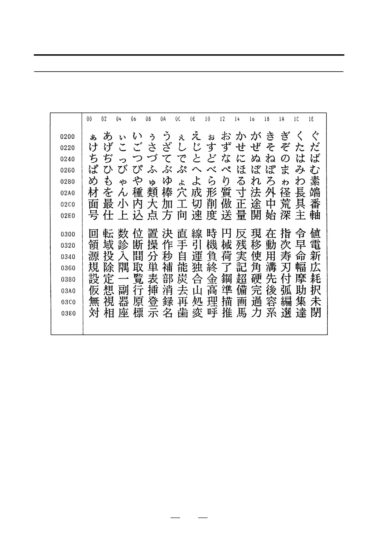
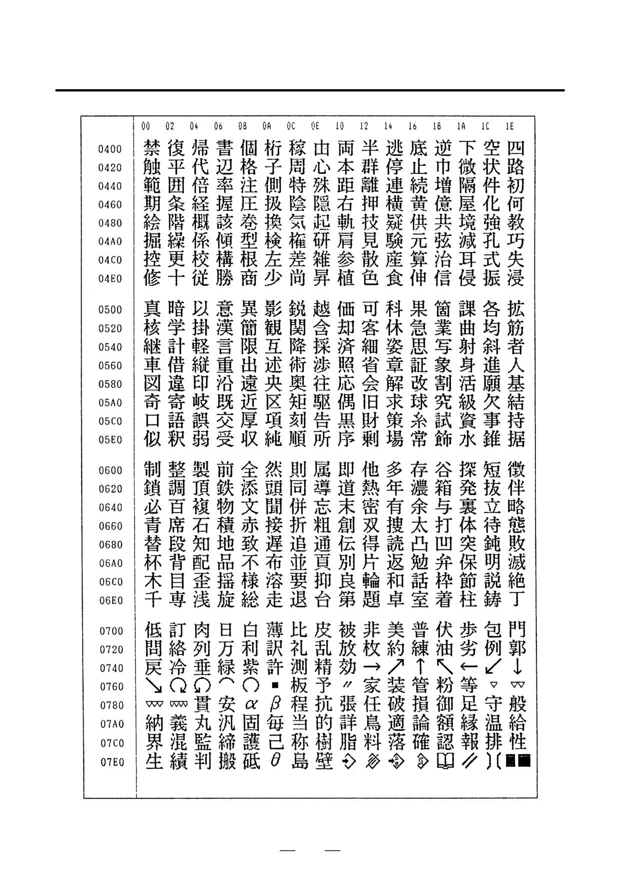
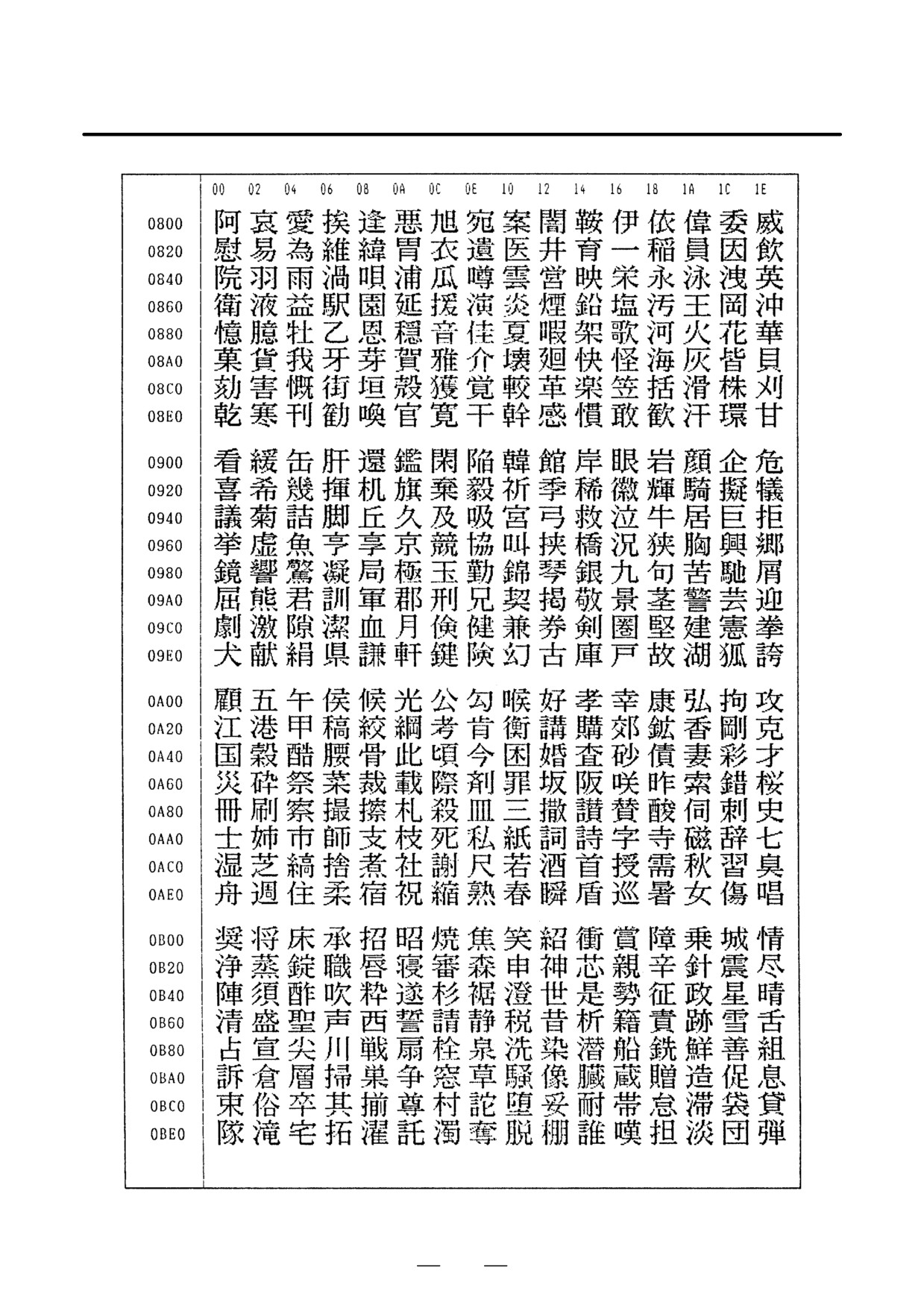
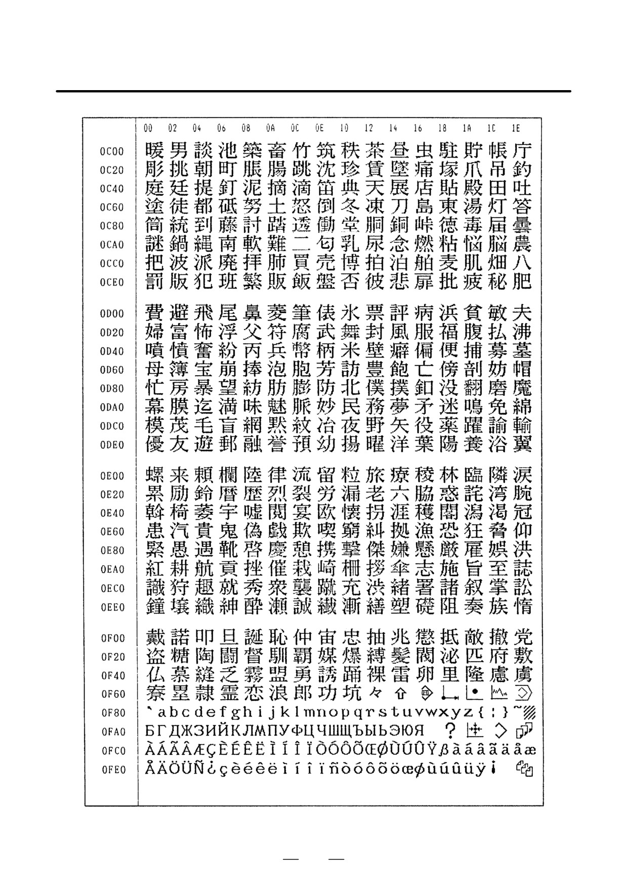
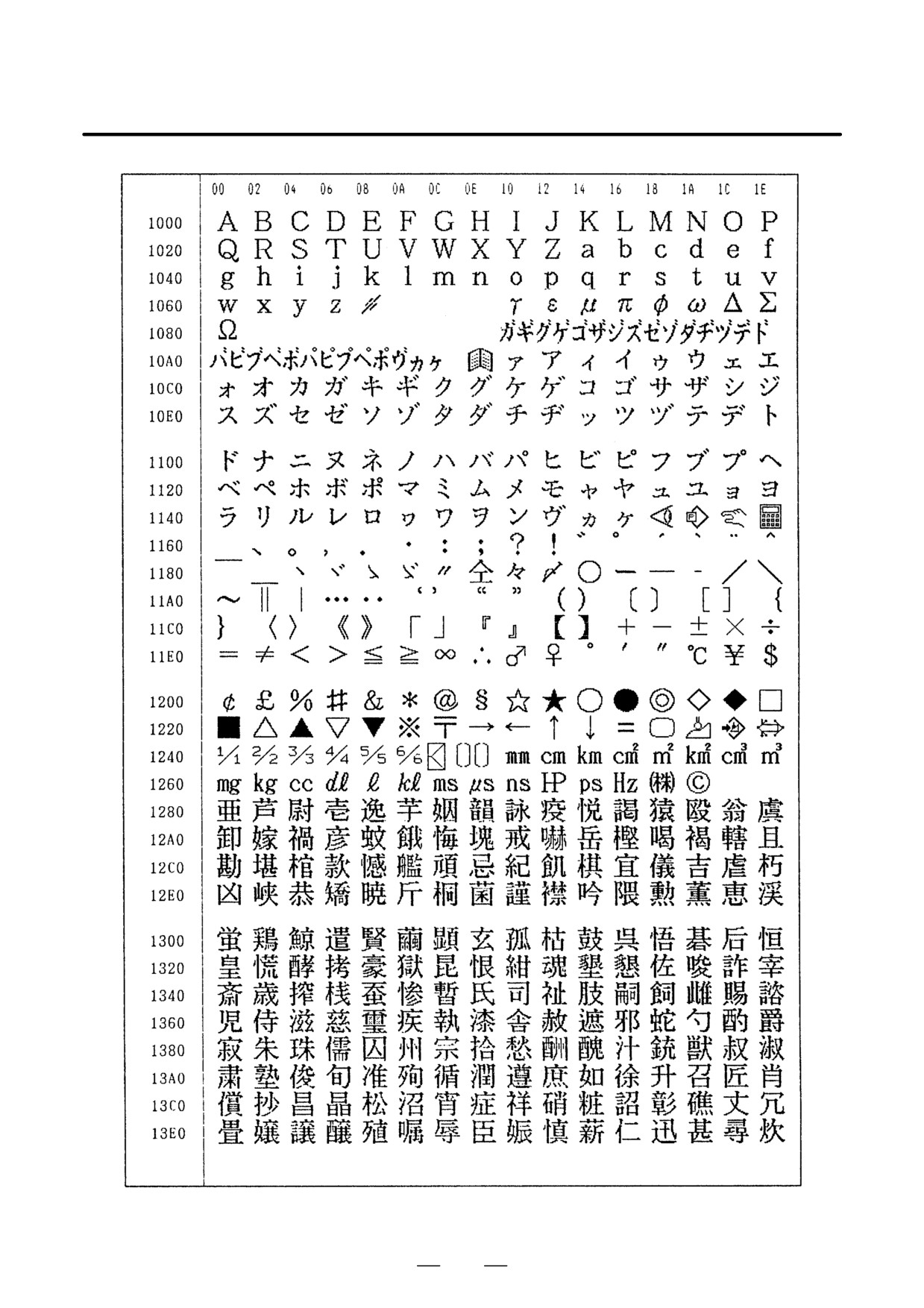
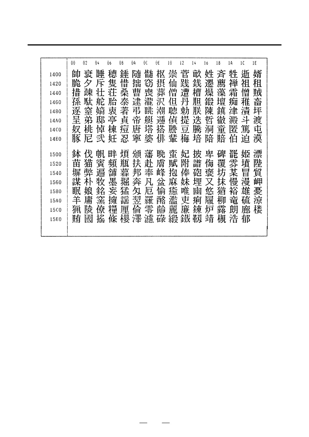
1.19.6
FANUC Two-Byte
Character Code Table
150
B-64115EN/02
1. DISPLAY AND OPERATION
151
1. DISPLAY AND OPERATION
B-64115EN/02
152
B-64115EN/02
1. DISPLAY AND OPERATION
153
1. DISPLAY AND OPERATION
B-64115EN/02
154
B-64115EN/02
1. DISPLAY AND OPERATION
155

2. HARDWARE
B-64115EN/02
HARDWARE
2
This chapter describes the printed circuit boards of the CNC control unit
and card PCB functions on the printed circuit boards. The chapter also
describes procedures for replacing consumable items.
2.1
HARDWARE CONFIGURATION
157
2.2
HARDWARE OVERVIEW
158
2.3
TOTAL CONNECTION DIAGRAMS
160
2.4
CONNECTOR AND CARD
CONFIGURATIONS OF PRINTED
CIRCUIT BOARDS
163
2.5
UNITS AND PRINTED CIRCUIT BOARDS
200
2.6
REPLACING THE MAIN BOARD
204
2.7
MOUNTING AND DEMOUNTING CARD
PCBS
208
2.8
MOUNTING AND DEMOUNTING DIMM
MODULES
211
2.9
REPLACING FUSE ON CONTROL UNIT
213
2.10 REPLACING BATTERY
215
2.11 REPLACING FAN MOTORS
222
2.12 REPLACING LCD BACKLIGHT
225
2.13 DISTRIBUTED I/O SETTING
234
2.14 REPLACING FUSES ON VARIOUS UNITS
236
2.15 ENVIRONMENTAL REQUIREMENTS OUTSIDE
THE CONTROL UNIT
239
2.16 ACTION AGAINST NOISE
240
156
2. HARDWARE
B-64115EN/02
2.1
HARDWARE
CONFIGURATION
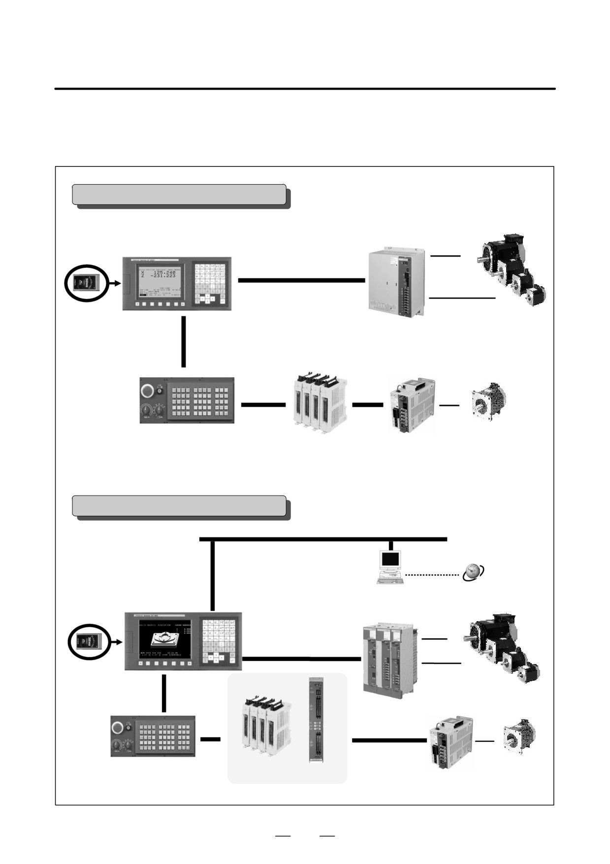
Series 0i Mate-C system configuration
βi spindle motors
βi SVSP
7.2″ LCD/MDI (monochrome)
FSSB
βiS servo motors
FANUC I/O Link
Maximum usable number of I/O points: 240 input points/160 output points
Distributed I/O
I/O Link βi servo amplifier
Machine operator’s panel
βiS servo motor (one axis)
I/O on the machine side
All units that can be connected with the I/O Link are usable.
The number of usable I/O points is limited, though.
Series 0i-C system configuration
Ethernet 10 base T/100 base TX (the Fast Ethernet board option is required.)
Internet
PC
7.2″ LCD/MDIJ (monochrome)
8.4″ LCD/MDI (color)
αi spindle motors
αi servo/spindle motors
FSSB
I/O on the machine side
FANUC I/O Link
αiS servo motors
DI/DO 1024/1024
The βi series is also usable.
Distributed I/O
βiS servo motor
Machine operator’s panel
I/O unit for the 0i
I/O Link βi servo amplifier
All units that can be connected with the I/O Link are usable.
157
2. HARDWARE
B-64115EN/02
2.2
HARDWARE
OVERVIEW
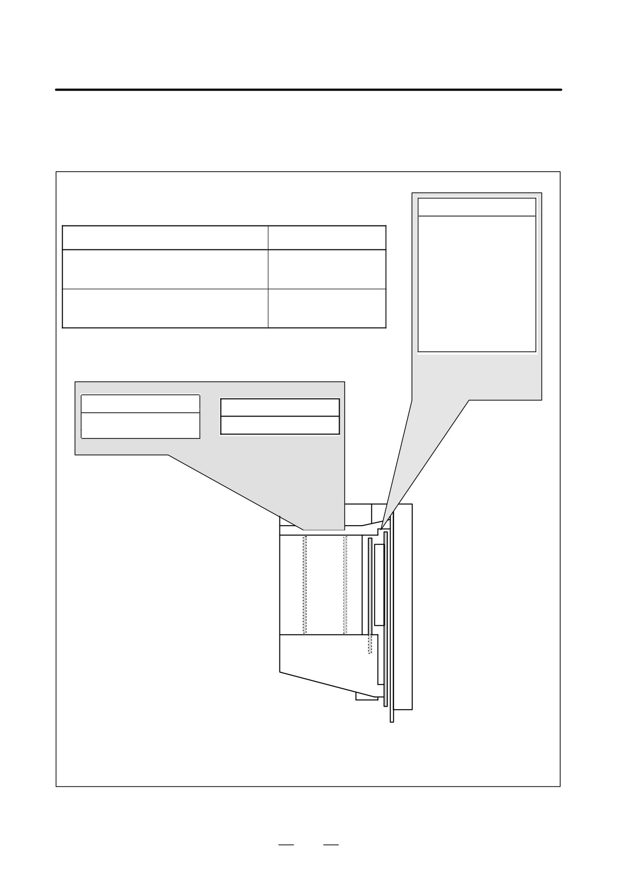
There are two types of basic units for Series 0i-C and Series 0i Mate-C:
Main board
CPU for controlling CNC
· Power supply
Basic unit drawing No.
Model
· 2-axis to 4-axis control
· Spindle interface
A02B-0309-B50n (n=0,1,...,9)
Series 0i -C
· LCD/MDI
A02B-0311-B50n(n=0,1,...,9)
Series 0i Mate-C
· I/O link
A02B-0311-B51n(n=0,1,...,9)
Series 0i Mate-C
· PMC-SA1/SB7
· Analog output/high-
A02B-0309-B52n(n=0,1,...,9)
Series 0i -C
speed DI
A02B-0311-B52n(n=0,1,...,9)
Series 0i Mate-C
· RS-232C × 2
A02B-0311-B53n(n=0,1,...,9)
Series 0i Mate-C
· Memory card interface
Basic system
Network board
DATA SERVER board
· Ethernet board
DATA SERVER function
· Profibus-DP board
Options
The control unit for the Series 0i has two option slots
or no option slots.
The control unit for the Series 0i Mate has no option slots, so an option board cannot be added.
On a unit with option slots, as many option boards as the number of option slots can be mounted.
(However, the option board must satisfy the mounting conditions. See the mounting conditions for addi-
tional options.)
Fig. 2.2 Configuration of the control unit (Series 0i/0i Mate)
158
2. HARDWARE
B-64115EN/02
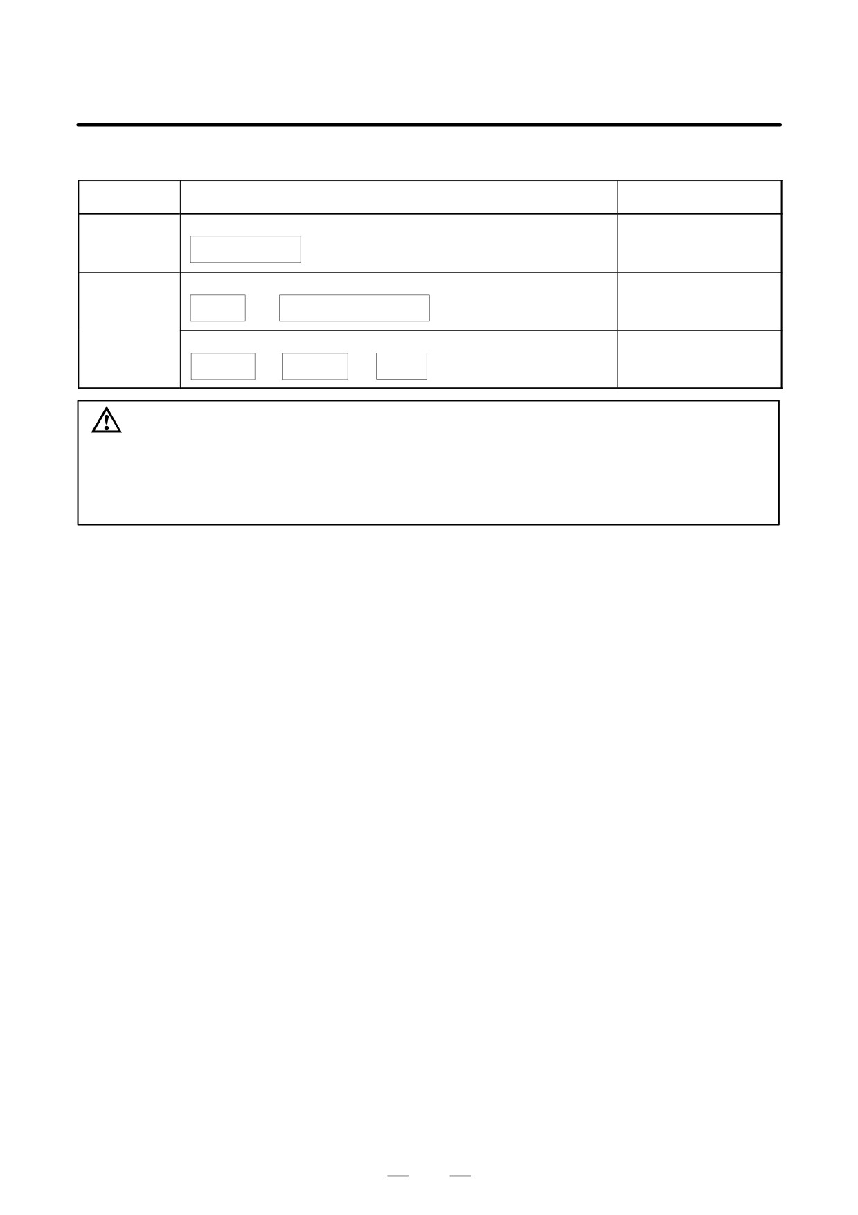
Conditions for installing options
Option
Slot nearest to the LCD
Data server
Data server board (ATA flash card and 100BASE-TX) 10BASE-T is also enabled
Ethernet and
data server functions
Network
Ethernet board (100BASE-TX) 10BASE-T is also enabled
Ethernet
Function
+
function
– FOCASI/DNC1/FACTOLINK
PROFIBUS board
PROFIBUS
PROFIBUS
Master
+
+
function
application
/slave
CAUTION
Each option listed above occupies one option slot. These option slots do not necessarily accept
all option types. When selecting option slots, therefore, pay attention to the number of option
slots. In this table, the symbol “
” indicates the option slot that does not accept the indicated
options. Some combinations of options are unacceptable.
159