FANUC Series 30i-MODEL B, 31i-MODEL B, 32i-MODEL B. MAINTENANCE MANUAL - page 27
D.MEMORY CARD SLOT
APPENDIX
B-64485EN/01
NOTE
2 The lock function is enabled only when a CF adapter (A02B-0303-K150) is used.
3 Insert a CF adapter so that the plane bearing the label faces the screen.
2.
Extraction
-
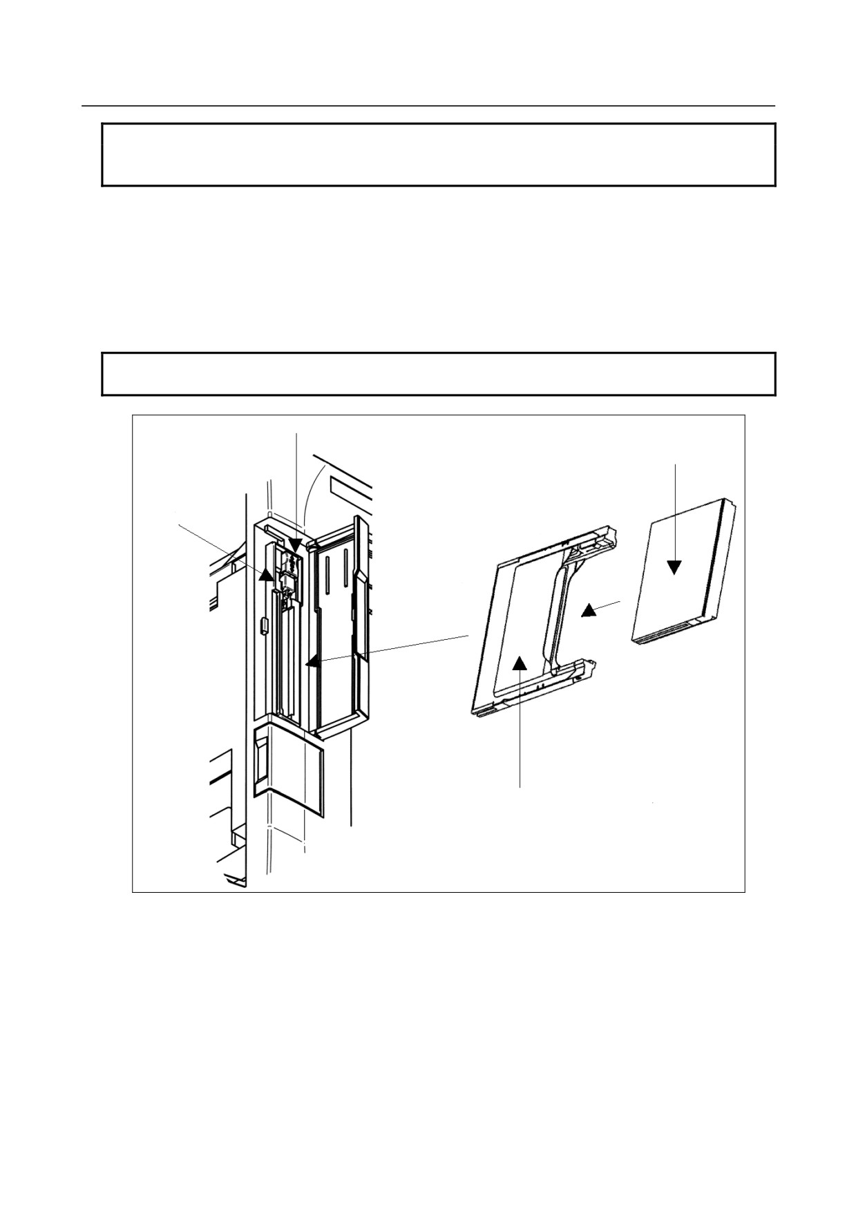
Open the cover of the memory card interface.
-
Push up lock lever A.
-
Push eject button B once. The button protrudes.
-
Push eject button B again. The CF adapter is ejected.
-
Hold the CF adapter with fingers and pull it out.
-
Close the memory card interface cover.
NOTE
When the lock lever is lowered (locked), the eject button cannot be pushed.
Lock lever A
Compact flash card
Eject button B
Compact flash card adapter
Fig. D.2 (a)
- 762 -
B-64485EN/01
APPENDIX
D.MEMORY CARD SLOT
D.3 HARDWARE CONFIGURATION
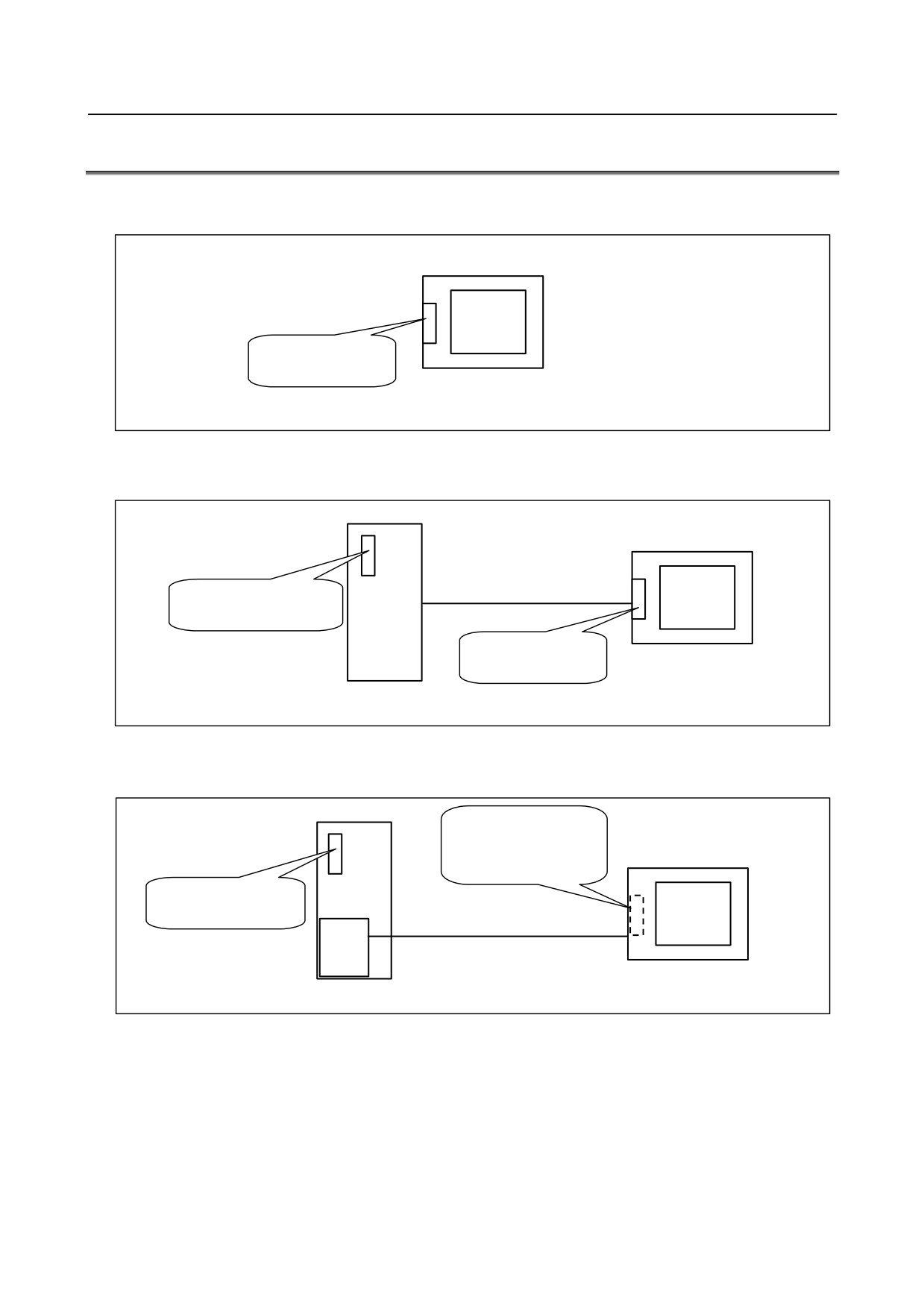
Type 1
LCD-mounted type
Card slot on
display unit side
Control unit (LCD-mounted type)
Fig. D.3 (a)
Type 2
Stand-alone type (with an LCD unit)
Optical cable
Card slot on control
unit side
Card slot on
display unit side
LCD unit for stand-alone type
Control unit (stand-alone type)
Fig. D.3 (b)
Type 3
When the HSSB interface is used to connect the personal computer or PANEL i
(Whe PANEL i is
used)
Card slot on display
unit side
Card slot on control
unit side
Optical cable
HSSB
board
Personal Computer or PANEL i
Control unit (stand-alone type)
Fig. D.3 (c)
- 763 -
E.LED DISPLAY
APPENDIX
B-64485EN/01
E LED DISPLAY
Appendix E, "LED DISPLAY", consists of the following sections:
E.1 OVERIVIEW
764
E.2
7-SEGMENT LED INDICATIONS (TURNED ON)
764
E.3
7-SEGMENT LED INDICATIONS (BLINKING)
766
E.1 OVERIVIEW
On the CNC, a 7-segment LED is installed.
The 7-segment LED indication changes according to the operating status of the CNC.
The 7-segment LED indications provided after the power is turned on until the CNC
is ready for
operation and when system errors occur are described below.
E.2
7-SEGMENT LED INDICATIONS (TURNED ON)
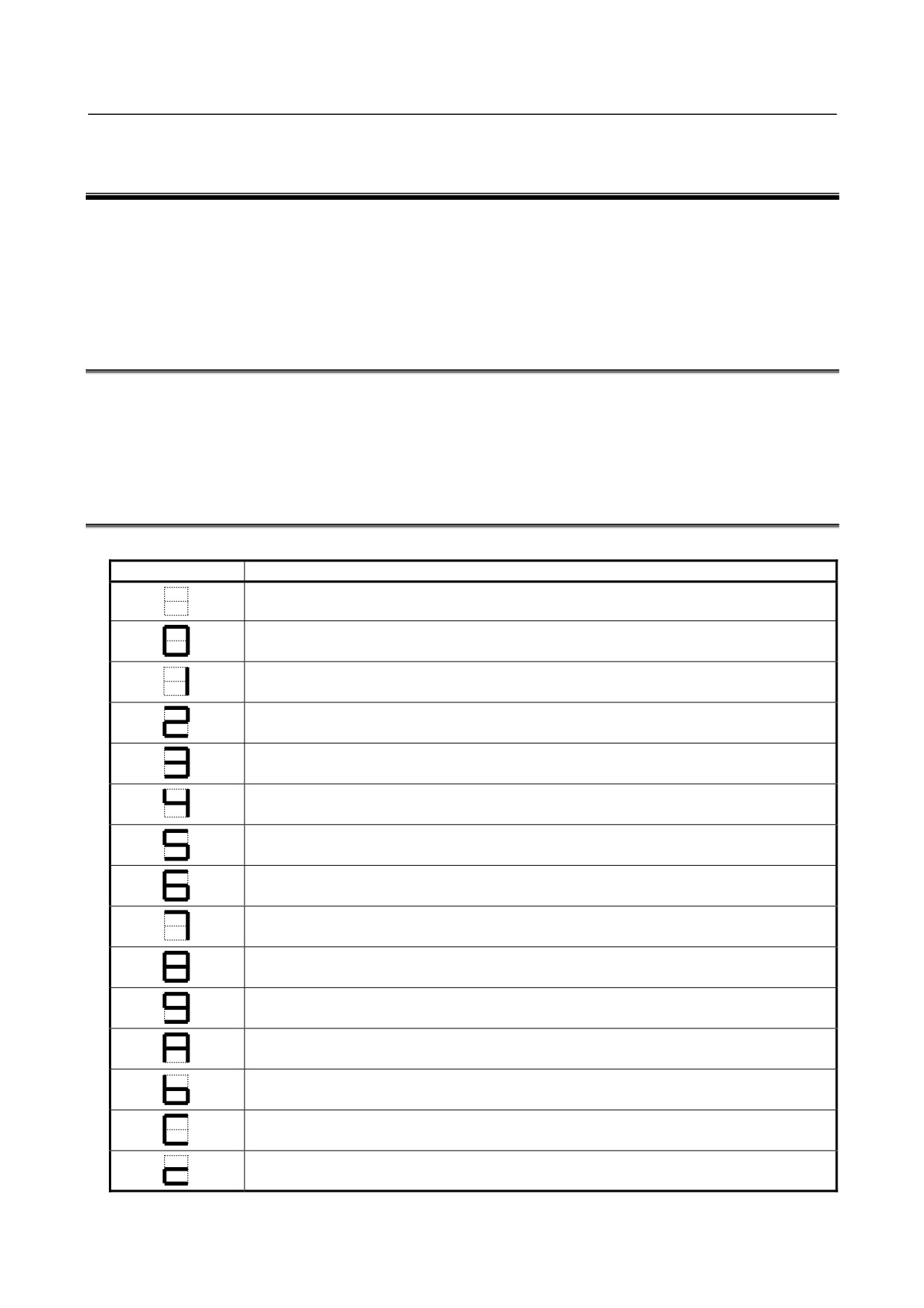
Table E.2 (a) Meanings of LED Indications
LED Display
Meaning
Power not turned on (power-off state)
Initialization completed and ready for operation
CPU started up
(BOOT system)
Initialization of G/A
(BOOT system)
Initialization of various functions
Task initialization
System configuration parameter check
Additional board waiting 2
Installation of various drivers
All files cleared
Title display
System ROM test
State where the CPU is not started after the power is turned on
(BOOT system)
BOOT system ended, NC system started
(BOOT system)
FROM initialization
Loading of embedded software
Loading of software for optional boards
IPL monitoring in progress
- 764 -
B-64485EN/01
APPENDIX
E.LED DISPLAY
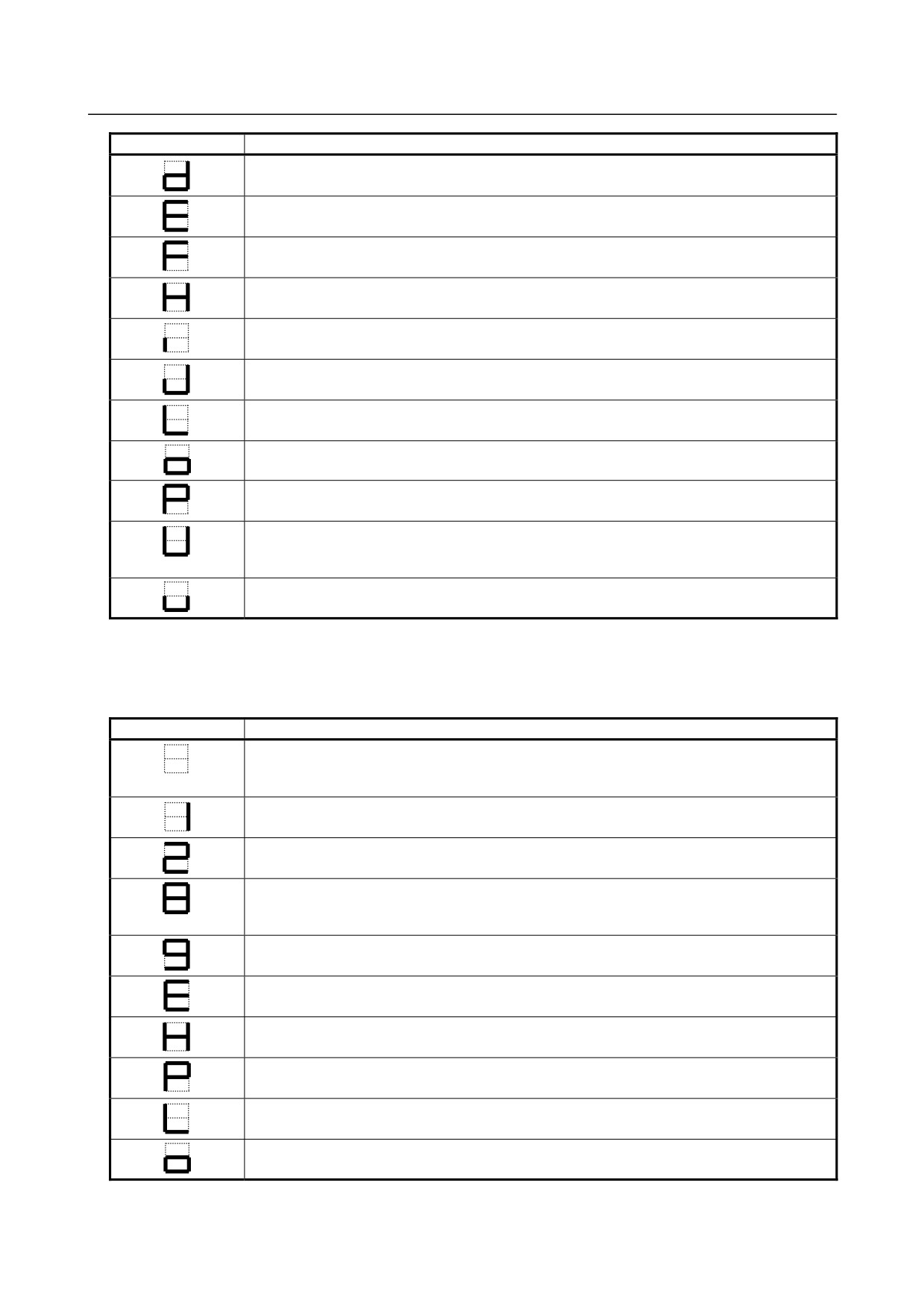
LED Display
Meaning
DRAM test error
(BOOT system, NC system)
BOOT system error
(BOOT system)
File cleared
Optional board waiting 1
Loading of basic system software
(BOOT system)
Fan motor check under way
(BOOT system)
Optional board waiting 3
Optional board waiting 4
Final system operation check
Fan motor faulty
(BOOT system)
Indicator initialization
(BOOT system)
FROM initialization
(BOOT system)
OPEN CNC BOOT (NCBOOT32) being executed
BOOT monitoring in progress
(BOOT system)
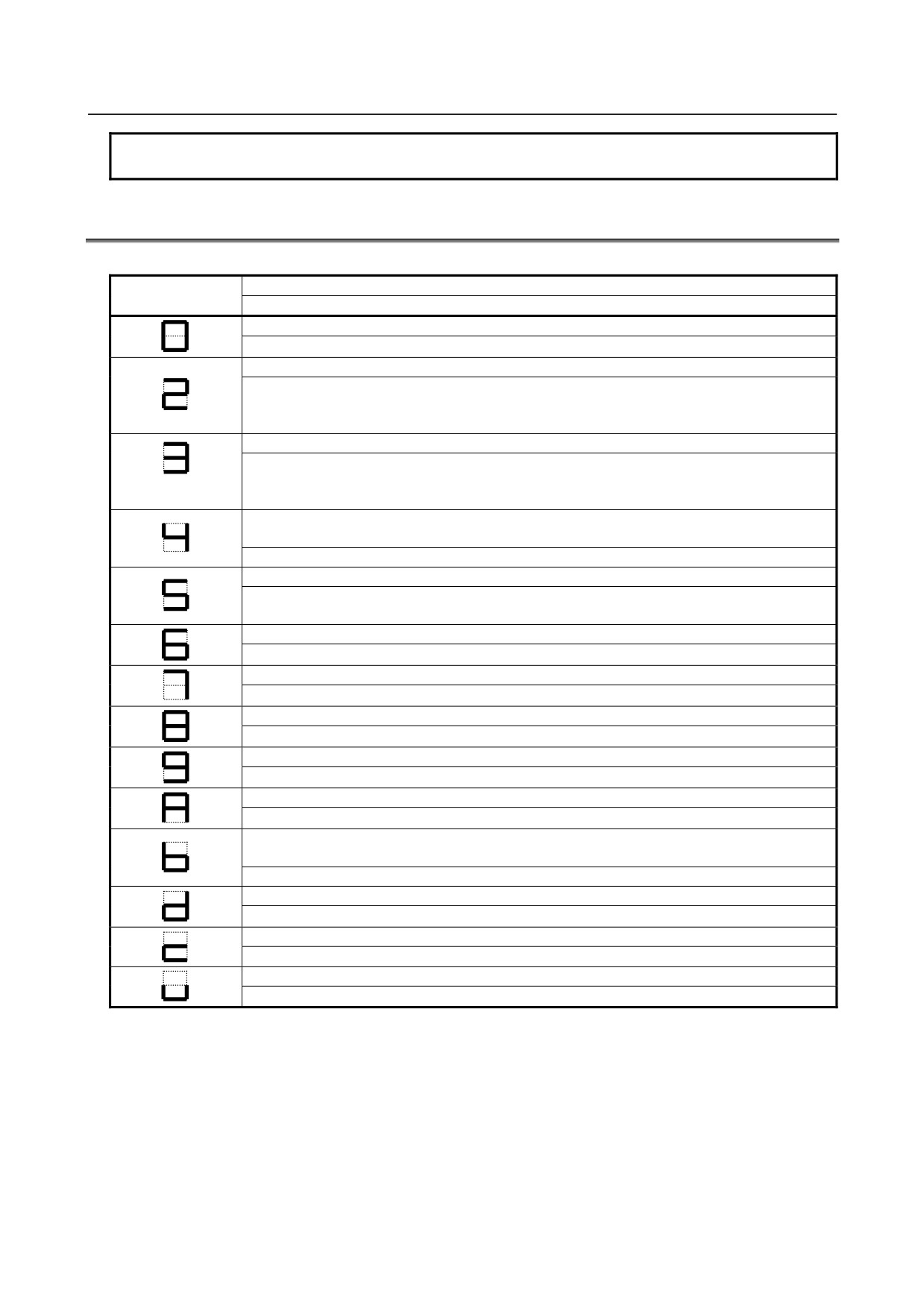
If processing stops during startup due to a CNC error, and the system alarm screen is not displayed, take
corrective action referring to Table E.2 (b).
Table E.2 (b) Faulty Regions and Check Items If Processing Stops during Startup
LED display
Faulty region and check item
The power supply (24V), backpanel (with power supply) (if the CNC is a LED-mounted type
control unit), or power supply unit (if the CNC is a stand-alone type control unit) may be
defective.
Check that the HSSB cable is attached correctly (if the CNC is a stand-alone type control
unit).
The main board or the stand-alone type display may be faulty.
Check the alarm LED "CCPUALM" (Note) on the main board.
If "CCPUALM" is lit : The CPU card may be fault.
If "CCPUALM" is not lit : The main board may be faulty.
The main board may be faulty.
The CPU card may be faulty.
The FROM/SRAM module or the main board may be faulty.
The main board or the stand-alone type display may be faulty.
The CPU card may be faulty.
The fan motor in the CNC control section may be faulty.
- 765 -
E.LED DISPLAY
APPENDIX
B-64485EN/01
NOTE
See Chapter 2 for descriptions of the location of the alarm LED “CCPUALM”.
E.3
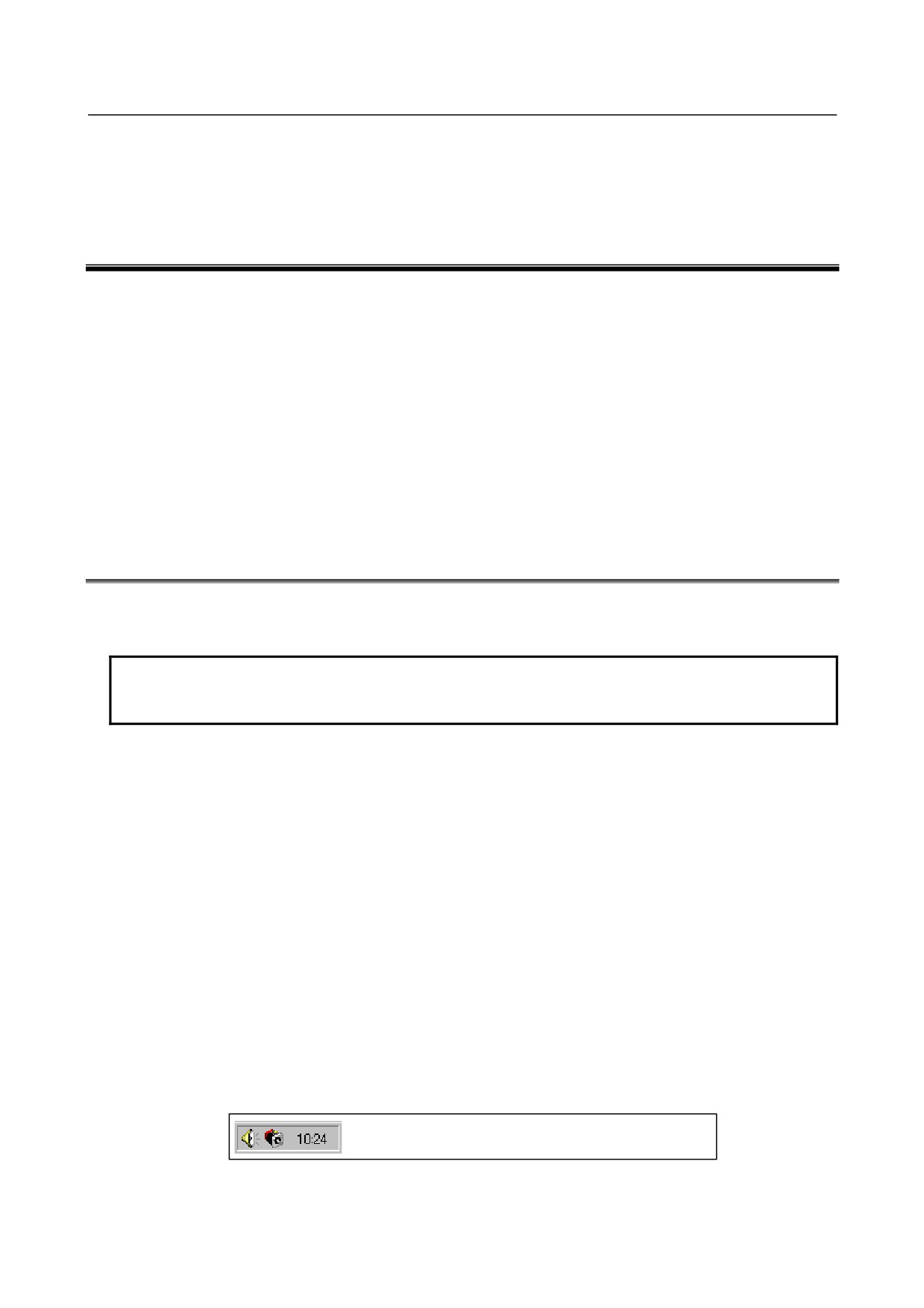
7-SEGMENT LED INDICATIONS (BLINKING)
Table E.3 (a)
Meaning
LED Display
Action
ROM PARITY error
The FROM/SRAM module may be faulty.
An FROM file for program memory cannot be created.
The state of the file for program memory on the FROM is checked with the BOOT system.
Rearrange the FROM.
Check the FROM size.
Software-detected system alarm
If it is generated during startup: Use BOOT to check the state of the built-in software in
FROM, and check the size of DRAM.
In other cases: Check the error on the alarm screen and take corrective action.
The DRAM/SRAM/FROM ID is invalid.
(BOOT system, NC system)
The CPU card or the FROM/SRAM module may be faulty.
A servo CPU timeout occurred.
Check the state of servo software on the FROM with the BOOT system.
The servo card or the additional axis board may be faulty.
An error occurred when embedded software is incorporated.
Check the state of embedded software on the FROM with the BOOT system.
The indicator cannot be recognized.
The display may be faulty.
Hardware-detected system alarm
Check the error on the alarm screen and take corrective action.
Software for optional boards could not be loaded.
Check the state of software for optional boards on the FROM with the BOOT system.
An error occurred in waiting for an optional board.
The option board or the PMC module may be faulty.
The BOOT FROM was updated.
(BOOT system)
Turn on the power again.
DRAM test error
The CPU card may be faulty.
The ID of the indicator is invalid.
Check the indicator.
The ID of the BASIC system software does not math that of the hardware.
Check the combination of the BASIC system software and the hardware
- 766 -
F.MAINTENANCE OF OPEN
B-64485EN/01
APPENDIX
CNC (BOOT-UP AND IPL)
F MAINTENANCE OF PERSONAL
COMPUTER FUNCTIONS (BOOT-UP AND
IPL)
Appendix F, "MAINTENANCE OF PERSONAL COMPUTER FUNCTIONS (BOOT-UP AND IPL)",
consists of the following sections:
F.1 OVERVIEW
767
F.2 CHANGING START SEQUENCES
769
F.3 EXPLANATION OF SCREENS
770
F.3.1 BOOT Screen
770
F.3.2 IPL Screen
773
F.4 OTHER SCREENS
774
F.4.1 CNC Alarm Screen
774
F.4.2 Status Screen (Personal Computer Functions with WindowsXP only)
775
F.4.3 Option Setting Screen
775
F.1
OVERVIEW
If the CNC is connected with a PC via HSSB using the PC functions in the CNC, Ncboot32.exe can be
used for the maintenance of the CNC.
NOTE
When the CNC is connected to the PC over Ethernet, use the standard LCD/MDI
or Ethernet display function (see Appendix H) for the maintenance of the CNC.
Unless otherwise specified, the following examples assume the use of Ncboot32.exe of the Personal
Computer Functions with WindowsXP.
Ncboot32.exe provides the following functions:
• BOOT screen (for CNC user data maintenance, SRAM backup, and so forth)
• IPL screen (for clearing SRAM, and so forth)
• Display of the CNC power-on screen
• Display of CNC alarm screen
• Re-connection in case of the occurrence of a communication error
• Start of a registered application program
• Automatic display of the BOOT/IPL screen during the next startup of the CNC (Personal Computer
Functions with WindowsXP only)
• Saving and restoration of auto backup data (Personal Computer Functions with WindowsCE only)
For Personal Computer Functions with WindowsXP, Ncboot32.exe is copied to the System 32 folder of
Windows during driver installation.
In addition, for Personal Computer Functions with WindowsCE, it has been installed in the Storage
Card\FANUC folder.
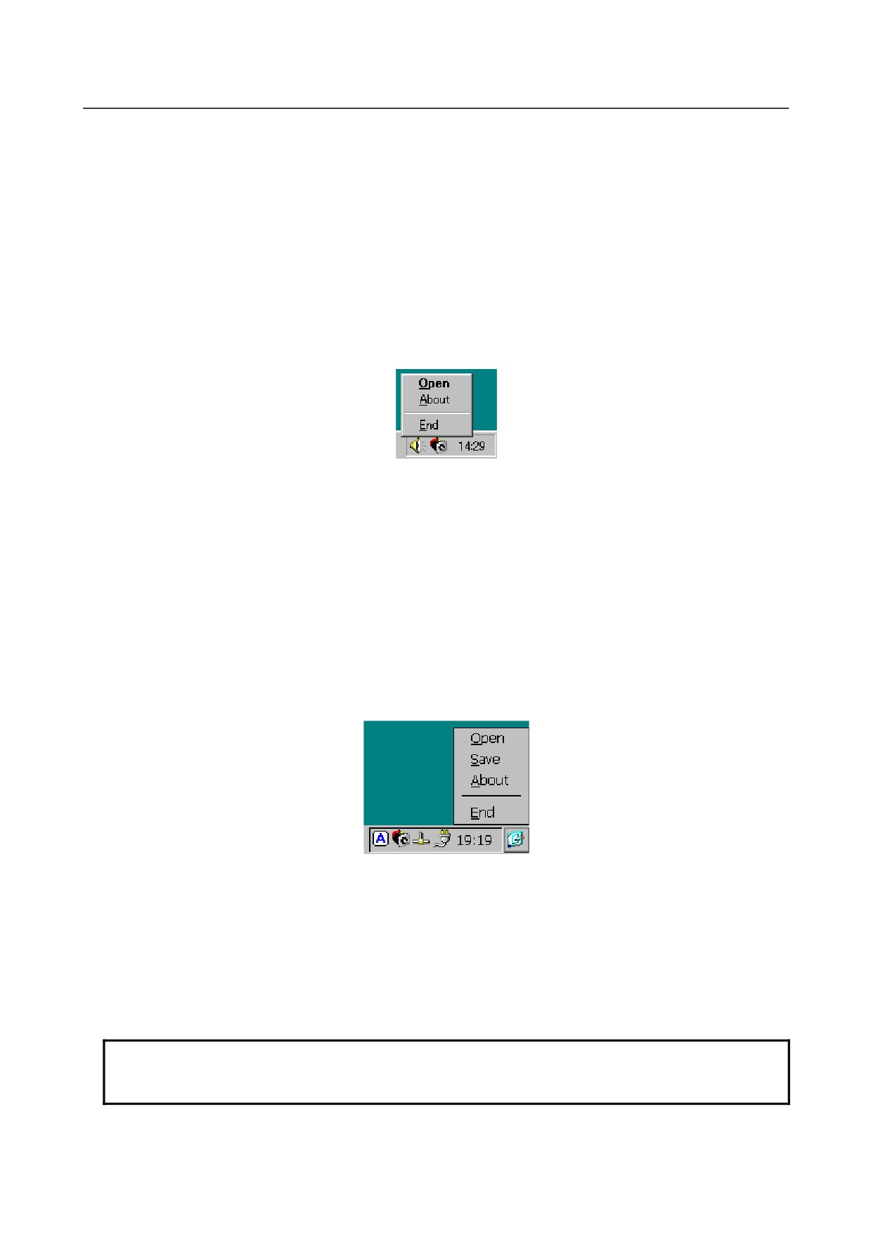
At the start of Windows, Ncboot32.exe starts automatically, and resides in the system tray.
(Icon at the center)
Fig. F.1 (a)
- 767 -
F. MAINTENANCE OF OPEN
CNC (BOOT-UP AND IPL)
APPENDIX
B-64485EN/01
Supplementary 1: Multi-connection (Personal Computer Functions with WindowsXP only)
Ncboot32.exe supports HSSB multi-connection. The CNCs connected by HSSB are managed as nodes.
The boot, IPL, and system alarm screens are displayed in windows that are opened independently for each
node.
Supplementary 2: Termination method
Normally, Ncboot32.exe need not be terminated. If you need to terminate it, however, see the "System
tray" explanation, below: Display the popup menu and select "End".
When the Ncboot32.exe window is open, End cannot be selected.
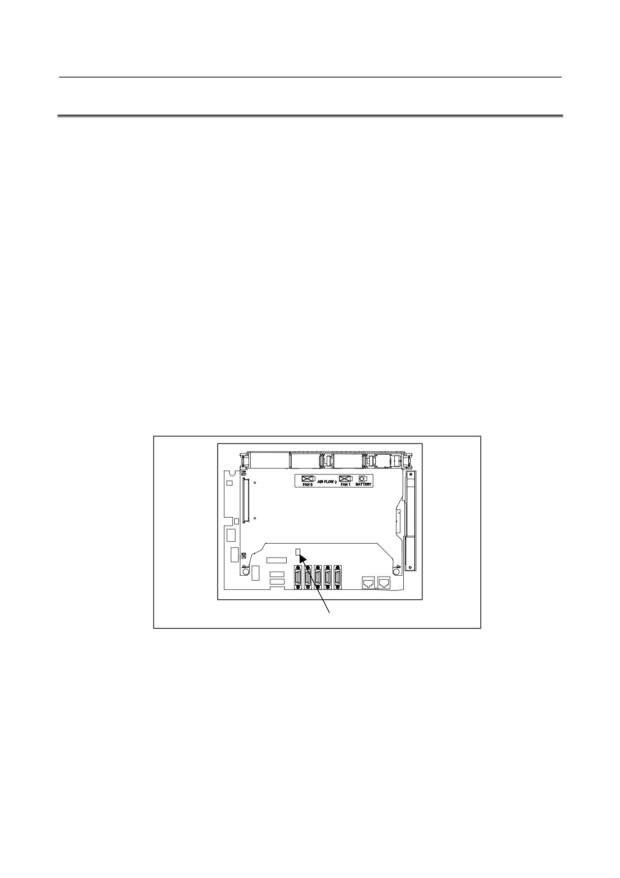
System tray (Personal Computer Functions with WindowsXP)
Right-click the icon in the system tray, and the popup menu, shown below, appears at the lower left
corner of the screen.
Fig. F.1 (b)
Selecting [Open] causes the status screen to open.
Selecting [About] causes the version information dialog box to appear.
Selecting [End] causes Ncboot32.exe to terminate.
Double-clicking the icon in the system tray causes Open in the menu to be automatically selected.
System tray (Personal Computer Functions with WindowsCE)
Keep tapping the icon in the system tray for one second or longer, and the popup menu, shown below,
appears at the lower left corner of the screen.
For equipment without a touch panel, the popup menu can be displayed by restarting "\Storage
Card\FANUC\Ncboot32.exe" with the icon having been registered in the system tray.
Fig. F.1 (c)
Selecting [Open] causes the option setting screen to open.
Selecting [Save] causes the contents of the Registry to be stored and causes the registered files to be saved
in the "\Storage Card\Backup" folder. If auto backup fails, the files in this folder are used for recovery.
Selecting [About] causes the version information dialog box to appear.
Selecting [End] causes Ncboot32.exe to terminate.
Double-clicking the icon in the system tray causes Open in the menu to be automatically selected.
NOTE
Depending on when to tap, the popup menu may not be displayed normally. If
this occurs, repeat tapping until it is displayed normally.
- 768 -
F.MAINTENANCE OF OPEN
B-64485EN/01
APPENDIX
CNC (BOOT-UP AND IPL)
F.2
CHANGING START SEQUENCES
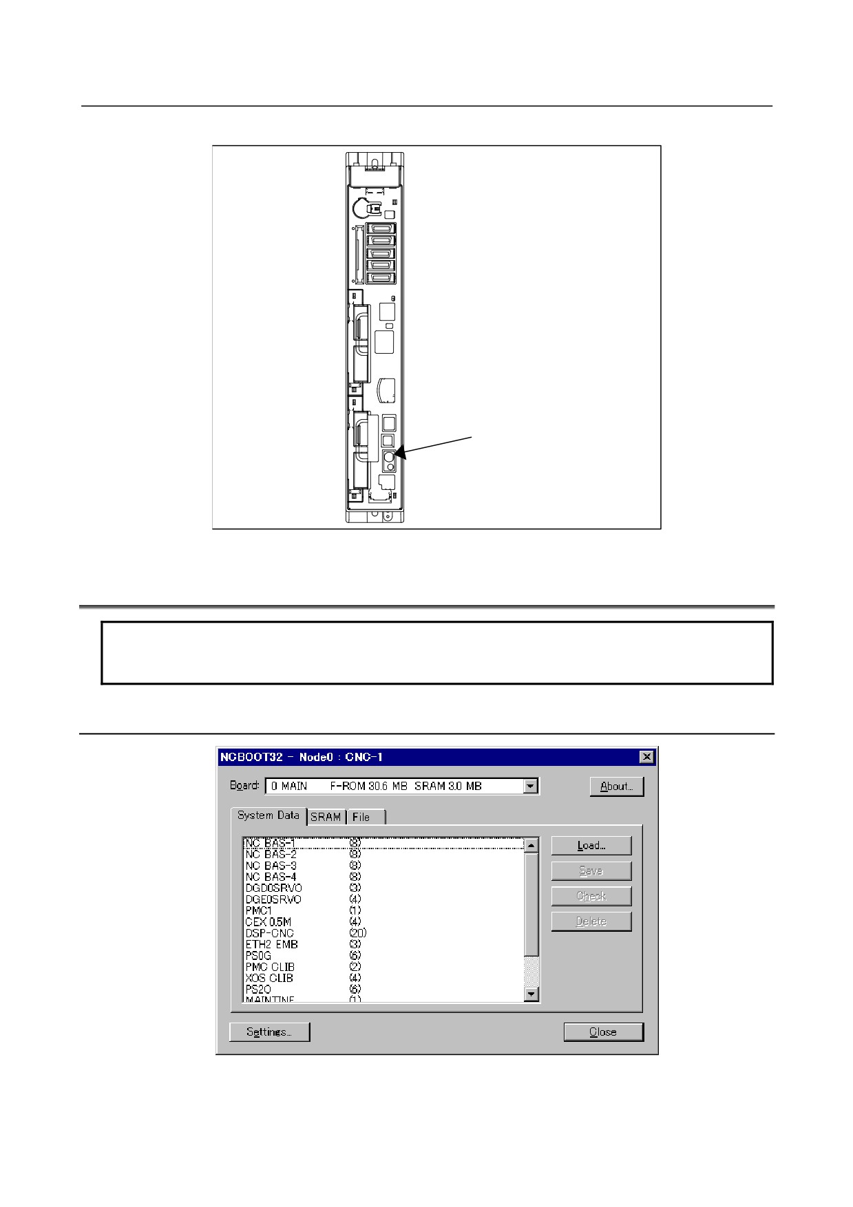
By pressing the MDI keys 6 and 7 and turning the power ON or by setting the rotary switch provided on
the main board of the CNC main unit (for the stand-alone type CNC or LCD-mounted type CNC) to the F
position, you can perform maintenance work using the BOOT and IPL screens.
During normal operation
1.
The CNC starts without waiting for communication to be established.
2.
The PC waits to be connected to the CNC for communication.
3.
Initialize a work area for the FOCAS2 library.
4.
Start a registered application program.
5.
Perform monitoring for communication errors and CNC system alarms.
During maintenance
1.
Wait until communication with the CNC is established.
2.
Display the boot screen.
3.
Display the IPL screen.
4.
Display the CNC power-on screen.
5.
Initialize a work area for the FOCAS2 library.
6.
Start a registered application program.
7.
Perform monitoring for communication errors and CNC system alarms.
• Location of rotary switch
• LCD-mounted type CNC
Rear view
Rotary switch
Fig. F.2 (a)
- 769 -
F. MAINTENANCE OF OPEN
CNC (BOOT-UP AND IPL)
APPENDIX
B-64485EN/01
• Stand-alone type CNC
Rotary switch
Fig. F.2 (b)
F.3
EXPLANATION OF SCREENS
NOTE
To open each screen of Ncboot32.exe, you are recommended to use either the
mouse or touch panel.
F.3.1
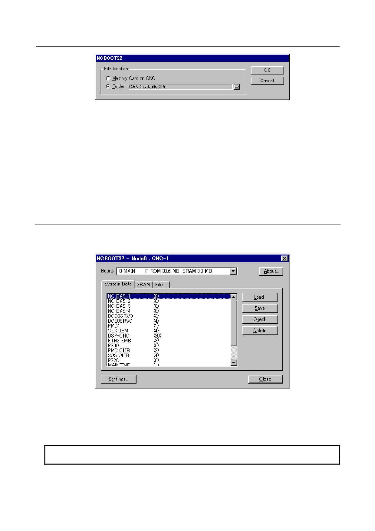
BOOT Screen
Fig. F.3 (a)
The area where the file is to be placed can be changed by using the [Setting...] button.
- 770 -
F.MAINTENANCE OF OPEN
B-64485EN/01
APPENDIX
CNC (BOOT-UP AND IPL)
Fig. F.3 (b)
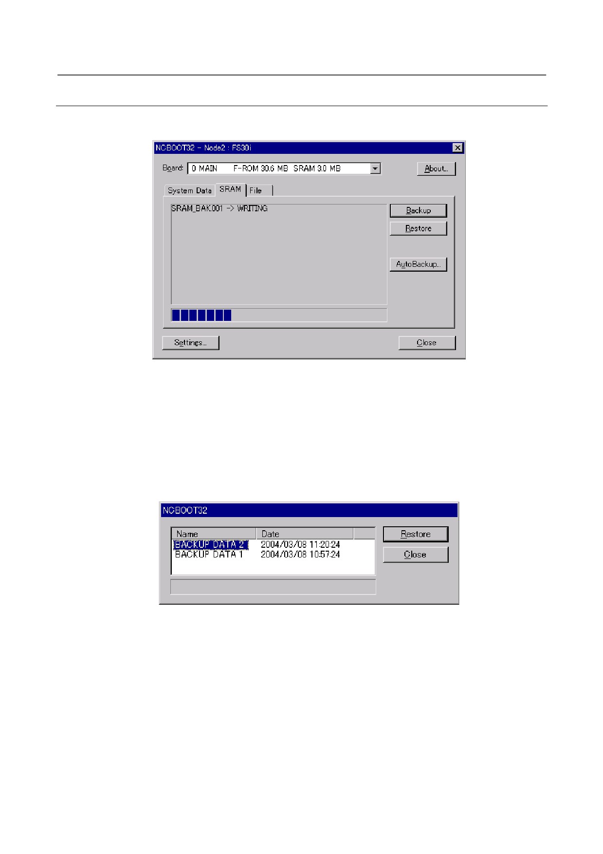
Select the memory card on the CNC or the folder on a personal computer. The file location may be
changed at any time.
"Memory Card on CNC":
Specify the memory card slot of the CNC.
1.
LCD-mounted type CNC : Beside the display unit
2.
Stand-alone type CNC (without a display unit) : Control unit
3.
Stand-alone type CNC (with a display unit) : Beside the display unit
(The display unit represents a LCD unit with no PC functions.)
"Folder":
Specify a folder on the PC.
To use the memory card slot beside PANEL i, select "Folder" and specify the drive name given to the
memory card by Windows.
F.3.1.1 User data manipulation
The following screen is used for manipulating user data (including ladder programs and macro programs)
on the NC.
Fig. F.3 (c)
[Load...] opens the file selection screen. Specify a file to be loaded.
[Save] saves the selected NC user data in a file.
[Check] checks the contents of the selected NC system data or user data.
[Delete] deletes the selected NC user data.
NOTE
It is impossible to load, save, or delete system data.
- 771 -
F. MAINTENANCE OF OPEN
CNC (BOOT-UP AND IPL)
APPENDIX
B-64485EN/01
F.3.1.2 SRAM operation
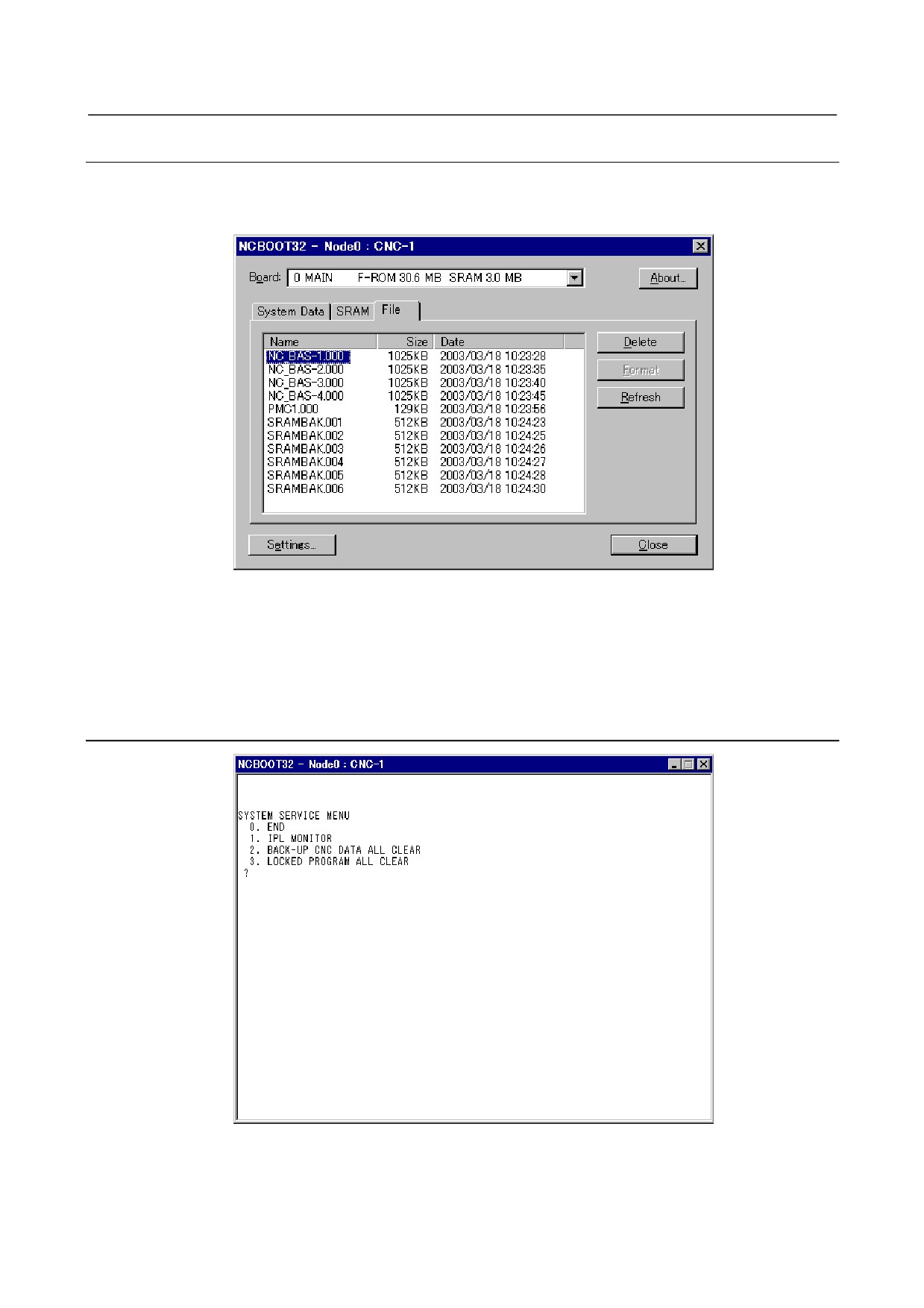
This screen is used to store and restore NC SRAM data.
Fig. F.3 (d)
[Backup]:
Saves SRAM data to a file.
[Restore]:
Restore SRAM data from a file.
The progress of the operation is indicated in the lower part of the screen. The name of the backup file is
automatically determined according to the SRAM size and cannot be changed.
The CNC has the function of automatically saving the data of SRAM in FROM. The personal computer
can restore the data that was saved automatically to SRAM. Press the [AutoBackup...] button to display
the following screen.
Fig. F.3 (e)
Select a saved image under "Name" and press the [Restore] button to restore the SRAM data of the
CNC.
- 772 -
F.MAINTENANCE OF OPEN
B-64485EN/01
APPENDIX
CNC (BOOT-UP AND IPL)
F.3.1.3 File operation
The following screen is used for operating files on a memory card in the CNC or in a folder of the
personal computer.
Fig. F.3 (f)
[Delete] deletes a selected file.
[Format] formats the memory card. This button is valid when the memory card is selected by [Setting...]
[Refresh] updates the file list to the latest state. After changing memory cards or floppy disks, click this
button.
F.3.2
IPL Screen
Fig. F.3 (g)
- 773 -
F. MAINTENANCE OF OPEN
CNC (BOOT-UP AND IPL)
APPENDIX
B-64485EN/01
NOTE
The contents of the IPL screen vary depending on the CNC model. Follow the
instructions displayed in the menu.
F.3.2.1 Functions on the IPL screen
The CNC allows functions to be performed according to the key status set at power-on.
No power-on time key operation can be performed with the personal computer function with Windows
XP or the personal computer function with Windows CE.
Instead, the equivalent function on the IPL screen can be executed.
For details of the menu on the IPL screen and supported functions, see the table given in Section F.3.2.1.
Table F.3 (a)
Corresponding MDI key operation at power-on
Title on IPL screen
(Operation with a standard CNC)
0. EXIT
1. IPL MONITOR
<-> + <.>
2. BACK-UP CNC DATA ALL CLEAR
<DELETE> + <RESET>
3. LOCKED PROGRAM ALL CLEAR
<M> + <O>
F.4
OTHER SCREENS
F.4.1
CNC Alarm Screen
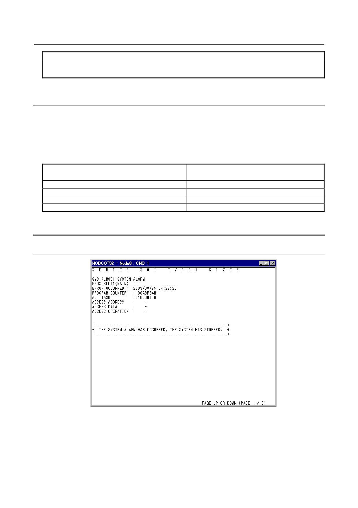
Fig. F.4 (a)
This screen appears when a system alarm is issued in the CNC. (The above screen is an example. The
displayed information varies depending on the system alarm issued in the CNC.)
- 774 -
F.MAINTENANCE OF OPEN
B-64485EN/01
APPENDIX
CNC (BOOT-UP AND IPL)
F.4.2
Status Screen (Personal Computer Functions with
WindowsXP only)
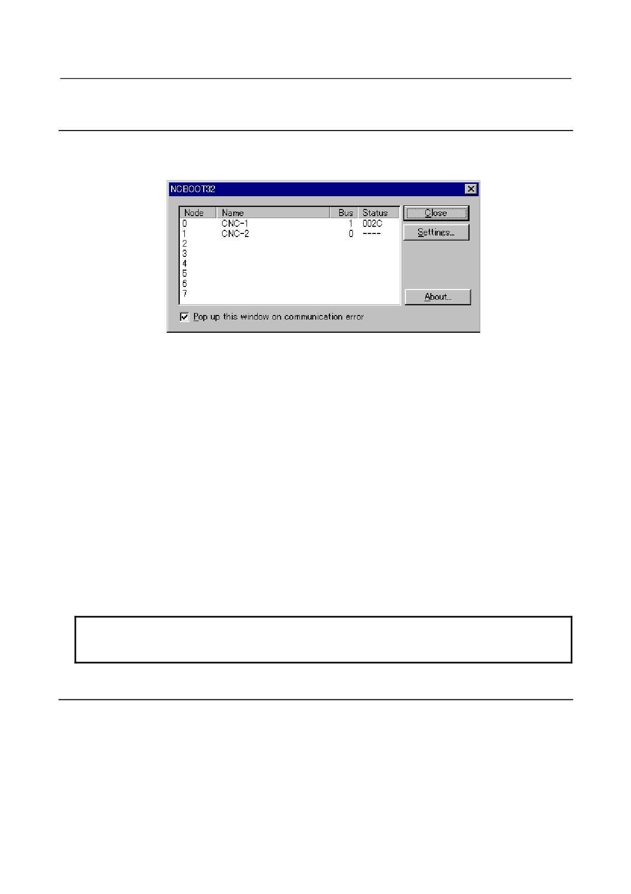
To open the status screen, double-click the icon in the system tray. Alternatively, in the menu popped up
by right-clicking, click “Open”.
Fig. F.4 (b)
Node: Node number
Name: Node name. (Define the node name in advance by using the HSSB applet on the control panel.)
Bus:
Hardware communication status (0: Communication error, 1: Communication established)
Status:
Status (in hexadecimal)
Bit 2:
End of boot processing
Bit 3:
End of IPL processing
Bit 4:
Rotary switch position 0
Bit 5:
Display of 30 lines on IPL/system alarm screen
Bit 7:
Internal flag
Bit 8:
CNC system alarm
Bit 9:
Internal flag
Bit 10:
Internal flag
Pop up this window on communication error: By checking this item, this screen is opened automatically
when a communication error occurs.
Clicking the [Close] button closes the screen.
Clicking the [Setting...] button opens the option setting screen.
Clicking the [About...] button opens the version information screen.
NOTE
The Personal Computer Functions with WindowsCE does not provide a status
screen.
F.4.3
Option Setting Screen
On the option setting screen, application programs can be registered.
Any programs for use with FOCAS2 will not run unless they are started after communication
establishment with CNC. By registering these programs in Ncboot32.exe, they can be executed in
synchronization with the start of FOCAS2.
For the Personal Computer Functions with WindowsCE, it is possible to perform auto backup and
configure MDI keys.
- 775 -
F. MAINTENANCE OF OPEN
CNC (BOOT-UP AND IPL)
APPENDIX
B-64485EN/01
F.4.3.1 Option setting screen (Personal Computer Functions with
WindowsXP)
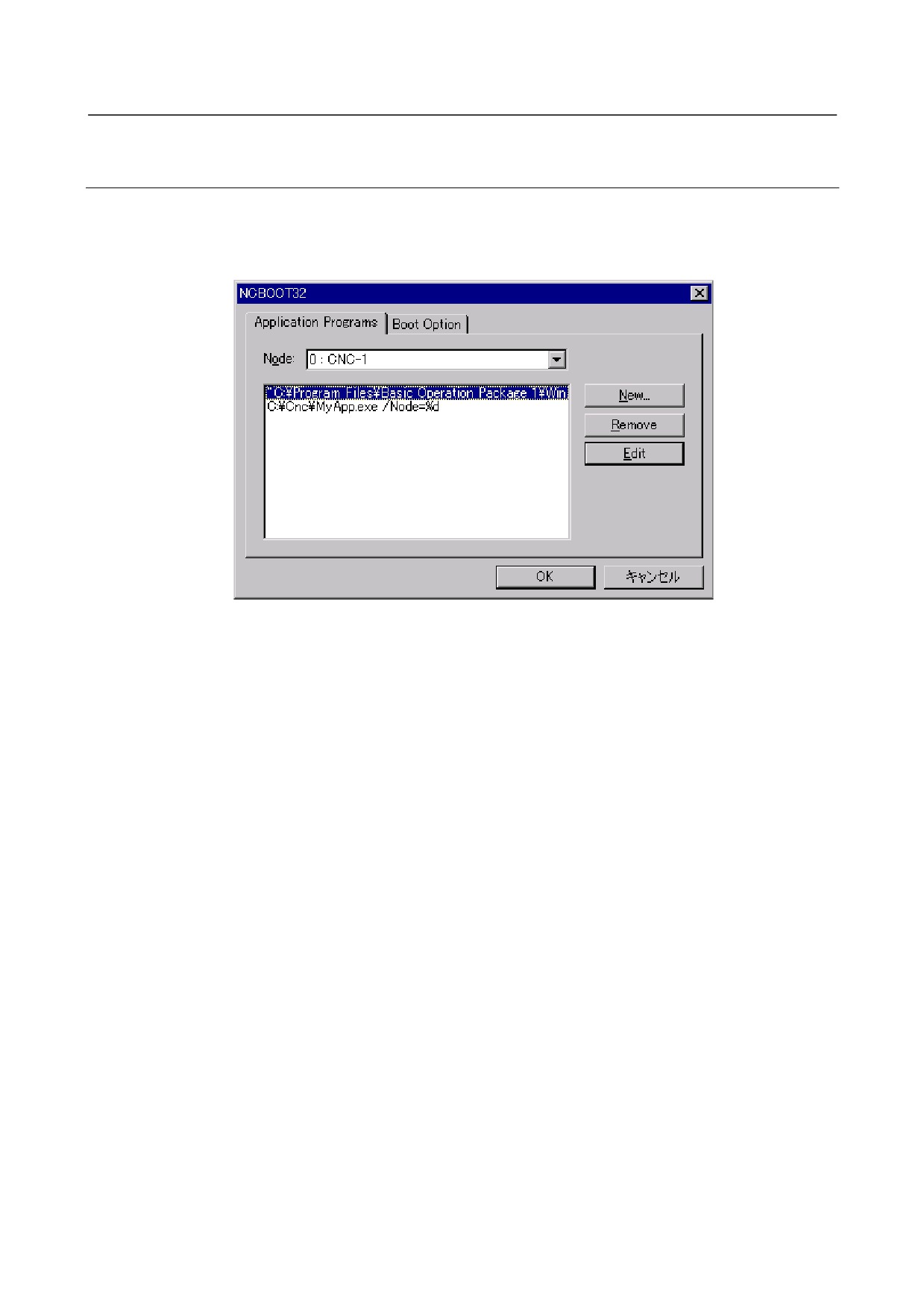
Clicking the [Settings...] button on the status screen causes the option setting screen to open. On the
option setting screen, an application must be registered with each node that requires it. In addition, it is
possible to set the display of the BOOT/IPL screen during the next startup of the CNC.
Fig. F.4 (c)
[Node] selects a node. In the list box in the center of the screen, the programs registered for the selected
node are displayed.
[New...] registers a new program. When a blank character is included in the path, it is enclosed with
double quotation marks.
[Remove] deletes a selected line.
[Edit] allows editing of a selected line. This button is used to edit arguments. The character string %d in
the command line is replaced by a node number. To represent % itself, describe %%.
Example: To start the CNC screen display function after FOCAS2 starts at that node, code the following:
“C:\Program Files\CNCScreen\CNCScrn.exe” /Node=%d
- 776 -
F.MAINTENANCE OF OPEN
B-64485EN/01
APPENDIX
CNC (BOOT-UP AND IPL)
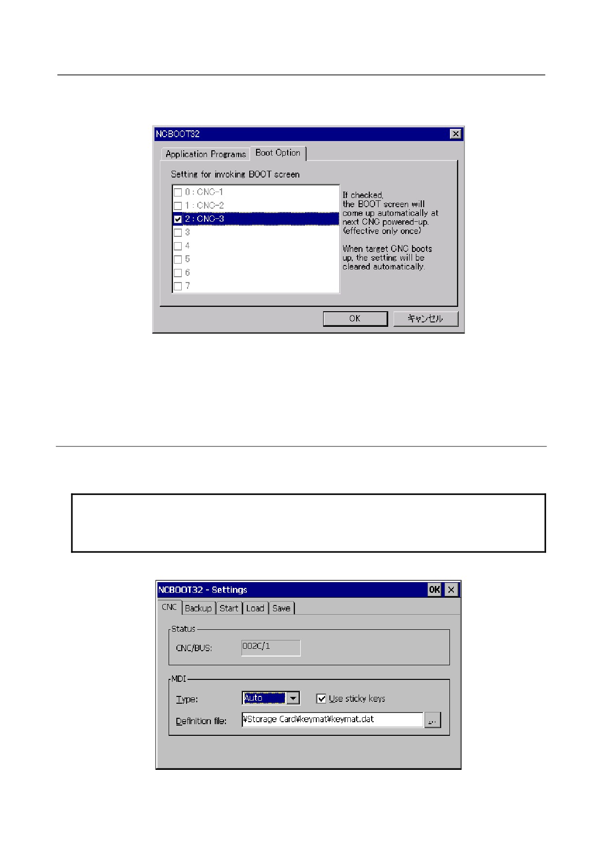
To set the display of the BOOT/IPL screen during the next startup of the CNC, select the "Boot Option"
tab on the option setting screen.
Fig. F.4 (d)
If a CNC that is not grayed out is checked, the BOOT/IPL screen appears during the next startup of the
CNC, regardless of the setting of the rotary switch on the CNC side. This display setting is enabled only
once and automatically cleared by Ncboot32.exe.
F.4.3.2 Option setting screen (Personal Computer Functions with
WindowsCE)
To open the option setting screen, double-tap the icon in the system tray. Alternatively, select [Open]
from the popup menu of the system tray.
NOTE
For any changes made on the option setting screen of the Personal Computer
Functions with WindowsCE to take effect, you must turn the power off and back
on.
CNC setting screen
Fig. F.4 (e)
- 777 -
F. MAINTENANCE OF OPEN
CNC (BOOT-UP AND IPL)
APPENDIX
B-64485EN/01
[Status]-[CNC] : Status (in hexadecimal)
Bit2 : End of boot processing
Bit3 : End of IPL processing
Bit4 : Rotary switch position 0
Bit5 : Display of 30 lines on IPL/system alarm screen
Bit7 : Internal flag
Bit8 : CNC system alarm
Bit 9: Internal flag
Bit 10: Internal flag
[Status]-[Bus] : Hardware communication status (0: Communication error, 1: Communication
established)
[MDI]-[Type] allows you to select an MDI key type.
Auto : QWERTY MDI key type, M and T series standard MDI key type
M series
:
MDI keyboard for M series
T series
:
MDI keyboard for T series
Selecting [MDI]-[Use sticky keys] allows you to use the functions of the Shift, Ctrl, and Alt keys without
pressing these keys in combination with other keys. For example, you can press Alt first and then 'F'
instead of pressing Alt and 'F' at the same time. If you remove the check mark, you must press Alt and 'F'
at the same time.
[MDI]-[Definition file] allows you to specify a customized MDI key definition file.
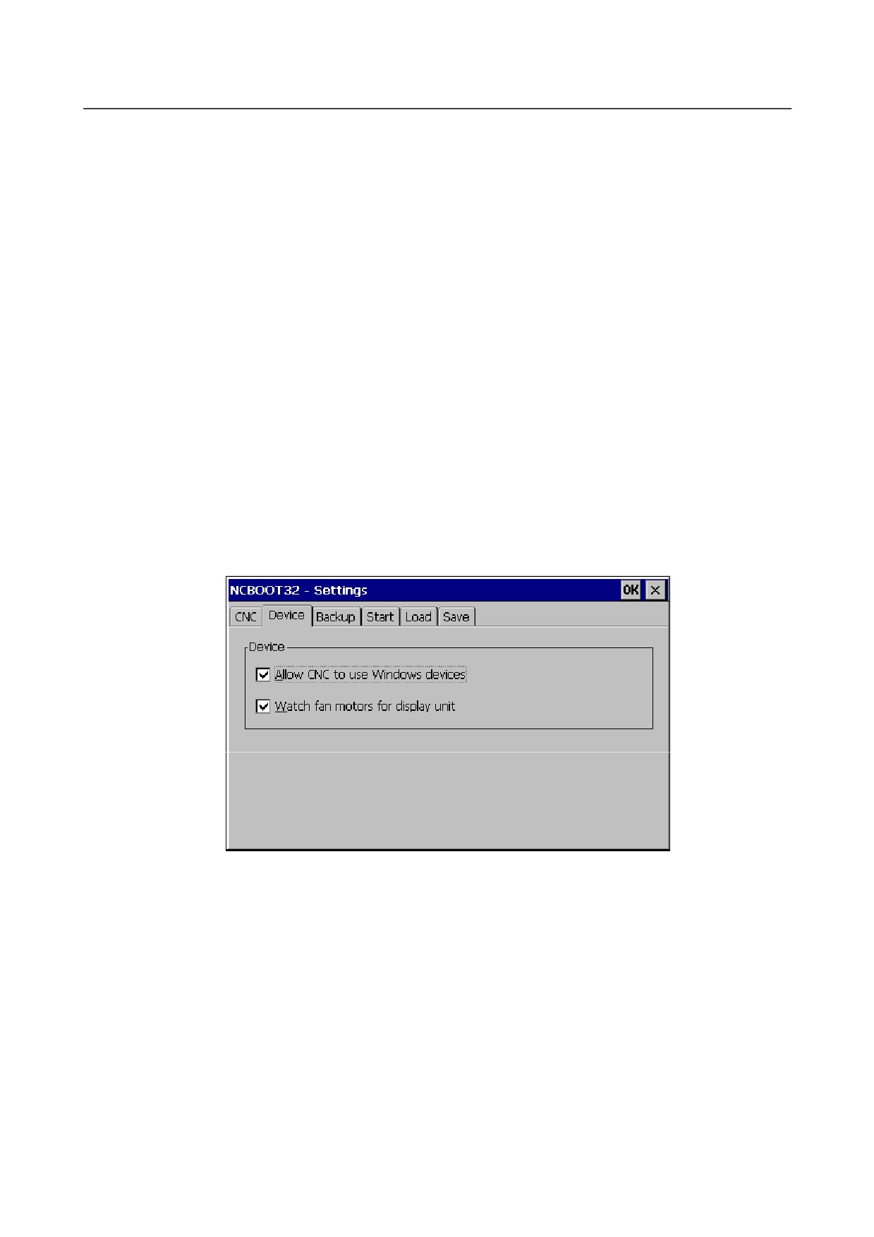
Device setting screen
Fig. F.4 (f)
Place a check mark next to [Allow CNC to use Windows devices] to make the devices on Windows
(Ethernet, serial, and PCMCIA devices) usable by the CNC.
Place a check mark next to [Watch fan motors for display unit] to check the operation of the display unit
of the stand-alone type CNC; if an error is detected, an error message is displayed.
- 778 -
F.MAINTENANCE OF OPEN
B-64485EN/01
APPENDIX
CNC (BOOT-UP AND IPL)
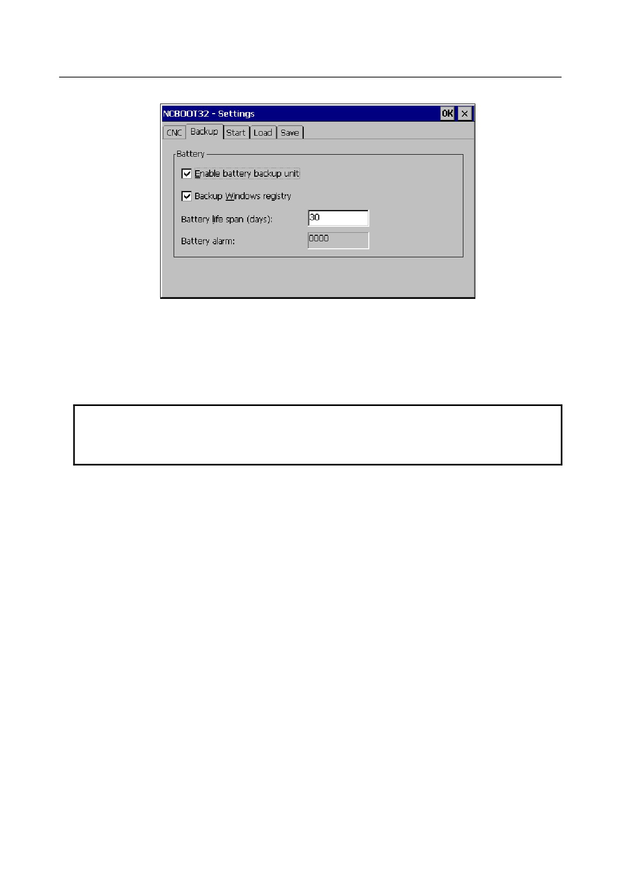
Backup setting screen
Fig. F.4 (g)
Place a check mark next to [Enable battery backup unit] to automatically save the contents of the Registry
and files when the power is turned off. A dedicated battery is used to supply power during a saving
operation after the power is turned off.
Place a check mark next to [Backup Windows registry] to automatically save the contents of the Registry
when the power is turned off.
NOTE
Usually, the contents of the Registry are not changed and, therefore, no
problems will arise if they are not automatically saved. You are recommended to
remove the check mark next to Auto saving of Registry just in case.
[Battery life span] allows you to set the number of days after which a message prompting you to save
manually is to be displayed during long-period operation.
[Battery alarm] indicates the state of the battery dedicated for backup (in hexadecimal notation).
0000 : Normal
0001 : The previous auto saving not completed
Other : Battery hardware error value
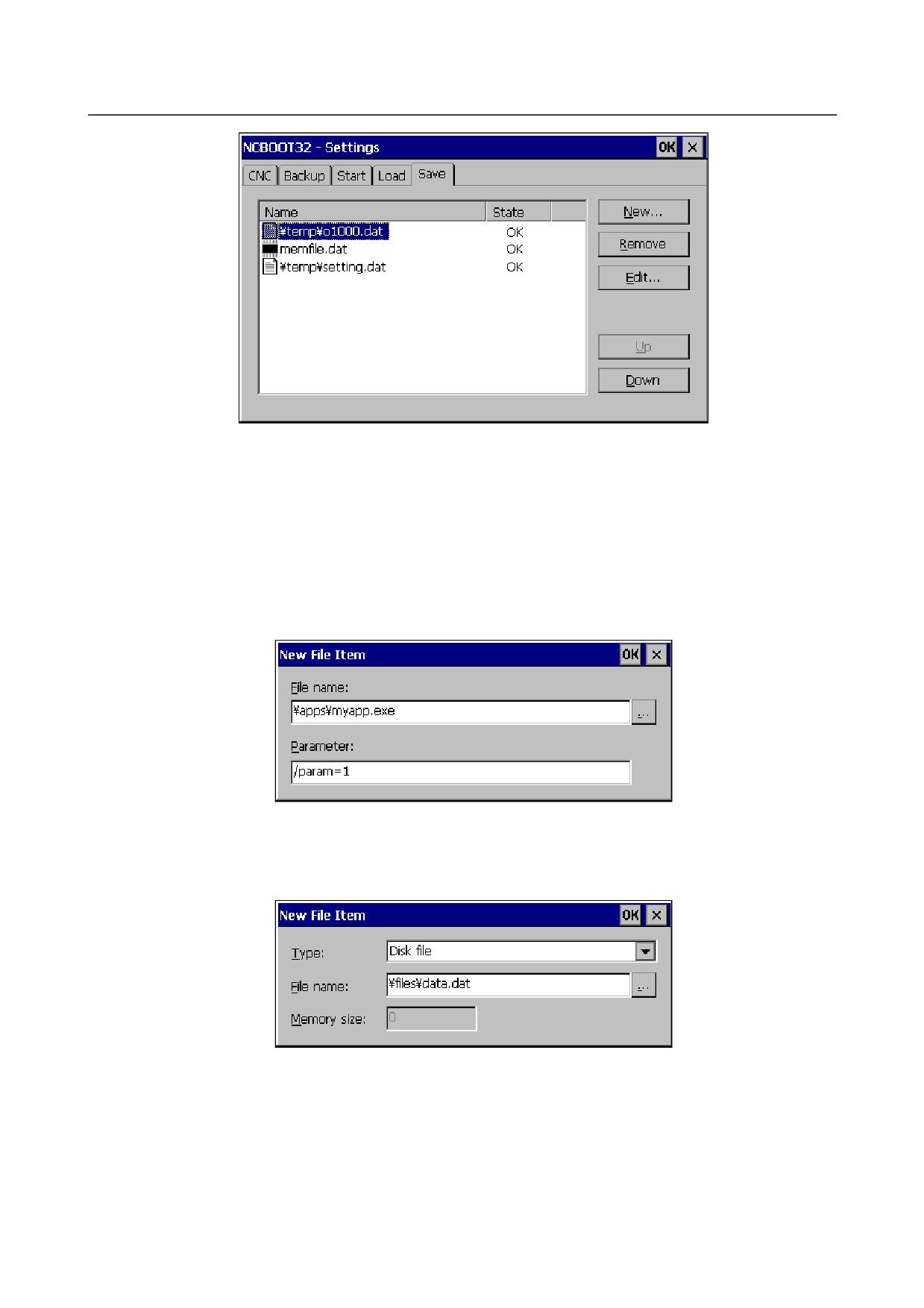
Start/Load/Save setting screen
This screen allows you to edit save, restore, and start files and to check execution results. Start allows you
to select the file to be started when the power is turned on. Save allows you to select the file to be saved
when the power is turned off. Load allows you to select the file to be restored when the power is turned
on.
The following shows the Save screen as an example. The screen layout and the main operating
instructions are common to the Start, Load, and Save screens.
- 779 -
F. MAINTENANCE OF OPEN
CNC (BOOT-UP AND IPL)
APPENDIX
B-64485EN/01
Fig. F.4 (h)
The [New...] button is used to register a new file.
The [Remove] button allows you to cancel the registration of the selected line.
The [Edit...] button allows you to change the changes made with the [New...] button.
The [Up] button is used to move a selected line up in the registration sequence.
The [Down] button is used to move a selected line down in the registration sequencer.
Pressing the [New...] button causes the following dialog box to appear, allowing you to specify a file.
- Start screen
Fig. F.4 (i)
In the [File name] field, specify a full path name of the file to be executed.
In the [Parameter] field, specify the program argument.
- Load/Save screen
Fig. F.4 (j)
[Type] is used to specify whether the file is on the Disk (object store) or it is a memory mapped file.
In the [File name] field, specify the full path name if the file is on the Disk; specify the name of the file
mapping object if it is a memory mapped file.
- 780 -

F.MAINTENANCE OF OPEN
B-64485EN/01
APPENDIX
CNC (BOOT-UP AND IPL)
NOTE
The name of a file mapping object is used as a temporary file for use during
saving and restoration. You must, therefore, specify a string characters effective
as a file name.
In the [Memory size] field, specify the size of the memory mapped file. For a file on the Disk, you need
not specify the size because it is calculated from the actual file name.
- 781 -
G. MAINTENANCE OF
STAND-ALONE TYPE UNIT
APPENDIX
B-64485EN/01
G MAINTENANCE OF STAND-ALONE TYPE
UNIT
Appendix G, "MAINTENANCE OF STAND-ALONE TYPE UNIT", consists of the following sections:
G.1 OVERVIEW
782
G.2 OPERATION
782
G.3 OPERATION OF EACH FUNCTION
783
G.1 OVERVIEW
Overview
The FANUC Series 30i/31i/32i of stand-alone type has a 7-segment LED, rotary switch, and push switch.
When there is no MDI or MDI cannot be used due to a malfunction, battery backed-up data can be saved
or restored if the rotary switch and push switch are operated.
NOTE
When MDI is available, use maintenance operation of the BOOT function.
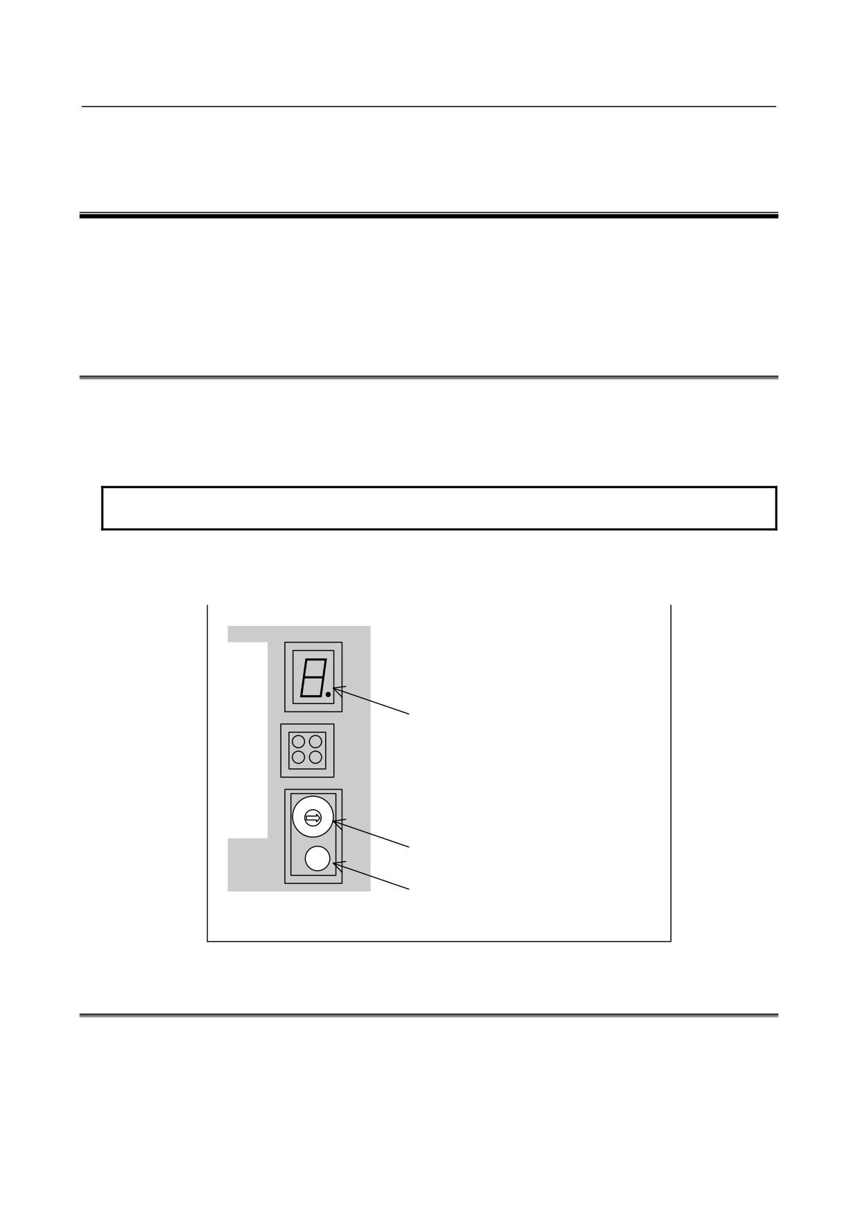
Layout of the 7-segment LED and switches
The 7-segment LED, the rotary switch, and the push switch are located as shown in the Fig. G.1 (a):
7-segment LED (STATUS)
Rotary switch (MTSW)
Push switch (PSW)
Fig. G.1 (a)
G.2 OPERATION
Operation before power-on
Before turning on the power, select a function number by using the rotary switch. When the power is
turned on after the selection with the rotary switch, the number corresponding to the selected function
number is indicated on the LED. The indication blinks at intervals of about one second.
- 782 -

G.MAINTENANCE OF
B-64485EN/01
APPENDIX
STAND-ALONE TYPE UNIT
Function number
Each function is assigned a number. This number is called a function number hereinafter in this manual.
The function numbers that can be selected with the rotary switch are listed below (Table G.2 (a)). Do not
set the reserved function numbers.
Table G.2 (a)
Function number
Explanation
0
Normal state.
1
Set a display unit number in the Ethernet Display function.
2
Set a node number in the Ethernet Display function.
3
Reserved
4
Checks settings in the Ethernet Display function.
5
Clears all data in memory.
6
Reserved
7
Reserved
8
Saves battery backed-up main board data in a memory card at a time.
9
Reserved
A
Restores battery backed-up main board data from a memory card at a time.
B
Reserved
C
Reserved
D
Reserved
E
Does not wait for the display unit.
F
Performs maintenance work.
G.3 OPERATION OF EACH FUNCTION
Function number 1
This function sets a display unit number in the Ethernet Display function.
(1) Check that number 1 blinks on the LED, and press the push switch.
(2) If the push switch is pressed, the 16 numbers from 0 to F are displayed on the LED in sequence at
one second intervals. When the display unit number to be set is displayed on the LED, press the
push switch.
0
: Not used.
1
: The HSSB connection display unit or CNC-specific display unit is set.
2 to 4
: Not used.
5
: The Ethernet connection display unit is set.
6 to F
: Not used.
(3) The selected display unit number blinks on the LED. Press the push switch again.
(4) The selected display unit number is displayed on the LED and saved in the CNC.
Function number 2
This function sets a node number in the Ethernet Display function.
(1) Check that number 2 blinks on the LED, and press the push switch.
(2) If the push switch is pressed, the 16 numbers from 0 to F are displayed on the LED in sequence at
one second intervals. When the node number to be set is displayed on the LED, press the push
switch.
The node number ranges from 0 to 7.
(3) The selected node number blinks on the LED. Press the push switch again.
(4) The node number is displayed on the LED and the display unit number is saved in the CNC.
Function number 4
This function checks settings in the Ethernet Display function.
(1) Check that number 4 blinks on the LED, and press the push switch.
- 783 -

G. MAINTENANCE OF
STAND-ALONE TYPE UNIT
APPENDIX
B-64485EN/01
(2) When the push switch is pressed, 0 and 1 are displayed on the LED alternately at one second
intervals. When 0 is displayed, press the push switch.
(3) The selected number 0 blinks on the LED. Press the push switch to stop blinking.
(4) The three numbers from 0 to 2 are displayed in sequence at one second intervals again. When the
number to be checked is displayed on the LED, press the push switch.
0
:
Not used.
1
:
A display unit number is checked.
2
:
A node number is checked.
(5) The selected number blinks. Press the push switch to stop blinking.
Function number 5
This function clears all the battery backed-up SRAM data.
The settings of the Ethernet Display function are also cleared and the display unit number and node
number are set to 1 and 0, respectively.
(1) Check that number 5 blinks on the LED, and press the push switch.
(2) Number 5 is displayed on the LED. Press the push switch.
(3) Display of the LED changes in the order: "-", "F", and "0".
(4) After all-clear operation terminates normally, the LED display stops changing at number 0.
(5) Turn off the power, return the rotary switch to the original position, and turn on the power again.
WARNING
1 This operation enables the CNC system to start up solely (initial state).
Accordingly, to recover various functional operations, the cleared data needs to
be set again.
2 This operation can be performed by those personnel who received the training of
maintenance and safety.
Function number 8
This function saves battery backed-up main board data in a memory card at a time. The data saved using
this function can be restored at a time by performing the operation for function number A or by using the
SRAM DATA UTILITY function of the boot function.
(1) Inset a memory card with enough free space into the memory card slot (MEMORY CARD CNM1B)
of the main body.
(2) Check that number 8 blinks on the LED, and press the push switch.
(3) Number 8 is displayed on the LED. Press the push switch.
(4) While data is saved in the memory card, display of the LED is rotating clockwise.
(5) If the data cannot fit in one memory card, number 3 blinks. Replace the memory card with another
one, and press the push switch.
(6) If the data cannot be written to the memory card, number 2 blinks on the LED. Replace the memory
card with another one and press the push switch.
(7) When the data has been saved normally, number 0 is displayed on the LED. If the data cannot be
saved normally, number 1 is displayed on the LED.
(8) If the data cannot be backed up because it is illegal, number 1 blinks on the LED. In this case, it is
impossible to save the data at a time. Back up individual data items one by one, then perform
all-clear operation.
Function number A
This function restores battery backed-up main board data from a memory card at a time.
(1) Insert the memory card in the memory card slot (MEMORY CARD CNM1B) of the control unit.
(2) Check that A blinks on the LED, and press the push switch.
(3) When letter A is displayed on the LED, press the push switch.
(4) While data is being restored from the memory card, the LED indication turns counterclockwise.
- 784 -
G.MAINTENANCE OF
B-64485EN/01
APPENDIX
STAND-ALONE TYPE UNIT
(5) If the entire data cannot be restored from the single memory card, number 3 blinks. Replace the
memory card with the next memory card, and press the push switch.
(6) If the memory card cannot be recognized correctly, number 2 blinks on the LED. Check the memory
card status, and press the push switch.
(7) When the data has been restored normally, number 0 is displayed on the LED. If the data cannot be
restored normally, number 1 is displayed on the LED.
Function number E
This setting does not wait for the display unit. Use this setting for a configuration without a display unit.
- 785 -
H.ETHERNET DISPLAY FUNCTION APPENDIX
B-64485EN/01
H ETHERNET DISPLAY FUNCTION
Appendix H, "ETHERNET DISPLAY FUNCTION", consists of the following sections:
H.1 OVERVIEW
786
H.2 EXAMPLE OF NETWORK CONFIGURATION
787
H.3 DISPLAY UNIT NUMBER SETTING AND CONFIRMATION
790
H.3.1
Display Unit Number Setting
790
H.3.2
Display Unit Number Confirmation
791
H.4 NODE NUMBER SETTING AND CONFIRMATION
792
H.4.1
Method of Node Number Setting
792
H.4.2
Method of Node Number Confirmation
792
H.5 CHANGING START SEQUENCES
793
H.6 NCBOOT32E.exe
794
H.6.1
Boot Screen
795
H.6.2
File Storage Location Selection
796
H.6.3
User Data Operation
796
H.6.4
S-RAM Operation
797
H.6.5
File Operation
798
H.6.6
IPL Screen
799
H.6.7
CNC Alarm Screen
800
H.6.8
Status Screen
800
H.6.9
Option Setting Screen
801
H.6.10
Changer Screen
802
H.7 STARTING OF THE CNC SCREEN DISPLAY FUNCTION
803
H.1 OVERVIEW
Up to eight CNCs of stand-alone type and one PANEL i unit (which may be hereinafter referred to as a
personal computer) can be connected with each other via Ethernet to use the personal computer as a
display unit for the CNCs.
Hub
PANEL i
Ethernet
Embedded Ethernet
(embedded port)
Stand-alone type Series 30i/31i/32i
(Up to eight CNCs can be connected.)
Fig. H.1 (a)
- 786 -
B-64485EN/01
APPENDIX H.ETHERNET DISPLAY FUNCTION
• CNC screens that can be displayed and operated by Ethernet Display function
CNC screen for maintenance (NCBOOT32E.exe)
- Display and operation of the boot screen
- Display and operation of the IPL screen
- Display of the CNC power-on screen
- Display of the CNC alarm screen
CNC screen for normal operation (CNCScrnE.exe)
- Display and operation of the general CNC screen
• Number of connectable CNCs
Up to eight CNCs can be connected to one personal computer.
• Ethernet address setting
-
The IP address of a CNC is the half-fixed address 192.168.1.(10+N) [from 192.168.1.10 to
192.168.1.17]. The value of N at the end is set using a rotary switch. The IP address of the
personal computer needs to be fixed at 192.168.1.200.
The TCP port numbers 8193 and 8198 are used for the CNCs, and the UDP port number 8197
is used for the personal computer. (No port number needs to be set.)
-
When Ethernet Display function option is not selected, the IP address of a CNC connectable to
the personal computer is 192.168.1.10 only.
NOTE
1
When using Ethernet Display function, note the following:
• The screen update interval of Ethernet Display function is longer than that of a
CNC-dedicated display unit. Even when a higher-performance personal
computer is used, the screen update interval cannot be made shorter than that
of a CNC-dedicated display unit.
• When high-load machining such as high-speed and high-precision machining is
performed, Ethernet Display function is more affected than a CNC-dedicated
display unit, so a longer screen update interval may result.
• As described in Appendix H.2, "EXAMPLE OF NETWORK CONFIGURATION",
Ethernet Display function is designed for a system where multiple machines
share a display unit or a system that does not need a display unit usually. For
example, when using a machine that the machine operator operates by
displaying and operating the CNC screen at all times as in the case of using
MANUAL GUIDE i, use a CNC-dedicated display unit.
2
Only CNCs of stand-alone type can be used.
3
When Ethernet Display function is used, the PCMCIA Ethernet card cannot be
used. When using FANUC LADDER-III and SERVO GUIDE, use the embedded
port (Ethernet connector (CD38A) on the control unit).
4
Ethernet Display function cannot be operated with Fast Ethernet board.
5
When Ethernet Display function is used, the HSSB connection needs to be cleared
or the CNC-dedicated display unit needs to be disconnected.
6
For a personal computer (or PANEL i), select a CPU and memory size that can
sufficiently handle the connected CNCs and application software used. When
multiple CNCs are used, it is recommended to select Pentium III (866 MHz or
higher) for the CPU and a memory of 256 MB or more.
7
When PANEL i is used, the USB interface QWERTY MDI, FA full keyboard, or
general full keyboard is required. Refer to "FANUC PANEL i CONNECTION AND
MAINTENANCE MANUAL (B-64223EN)".
- 787 -
H.ETHERNET DISPLAY FUNCTION APPENDIX
B-64485EN/01
NOTE
8 When Ethernet Display function is used, the DHCP client function is automatically
disabled.
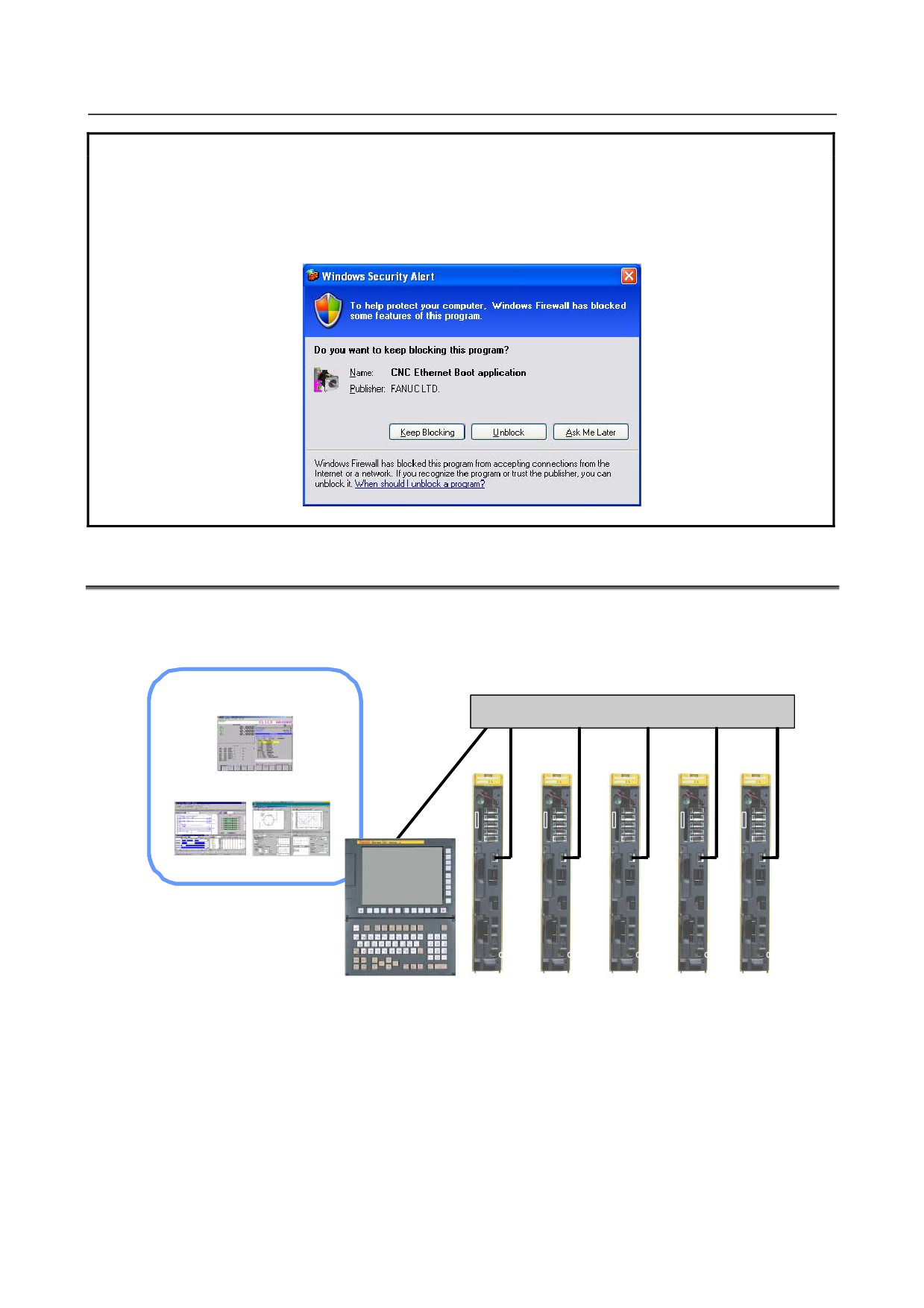
9 In a personal computer environment based on Windows XP Service Pack 2 or
later, a security warning screen as shown Fig. H.1 (b) is displayed when Ethernet
Display function is used for the first time. Select "Unblock".
Fig. H.1 (b)
H.2 EXAMPLE OF NETWORK CONFIGURATION
Example 1: When multiple CNCs share a display unit
PANEL i is shared as a display unit by five CNCs.
CNC screen display and operation
(permanent connection)
Hub
CNCScrnE
JA41
JA41
JA41
JA41
JA41
JA41
JA41
JA41
41
JA41
JA41
JA41
JA41
JA41
JA41
MME
JA
MM
E
JA
MME
JA
MME
MME
JA
ORY
41
R
OY
41
ORY
41
ORY
41
ORY
41
CA
JA41
C
A
JA41
CA
JA41
CA
JA41
CA
JA41
ET
ET
ET
ET
ET
HRE
HRE
HRE
HRE
HRE
LADDER-III SERVO GUIDE
CP1 CP2
CP1 CP2
CP1 CP2
CP1 CP2
CP1 CP2
OCP1
OCP1
OCP1
OCP1
OCP1
SLOT1
SLOT1
SLOT1
SLOT1
SLOT1
SLOT2
SLOT2
SLOT2
SLOT2
SLOT2
LED
LED
LED
LED
LED
1
1
1
1
1
LED
LED
LED
LED
LED
2SWI
2SWI
2SWI
2SWI
2SWI
TC
TC
TC
TC
TC
SPW
SPW
SPW
SPW
SPW
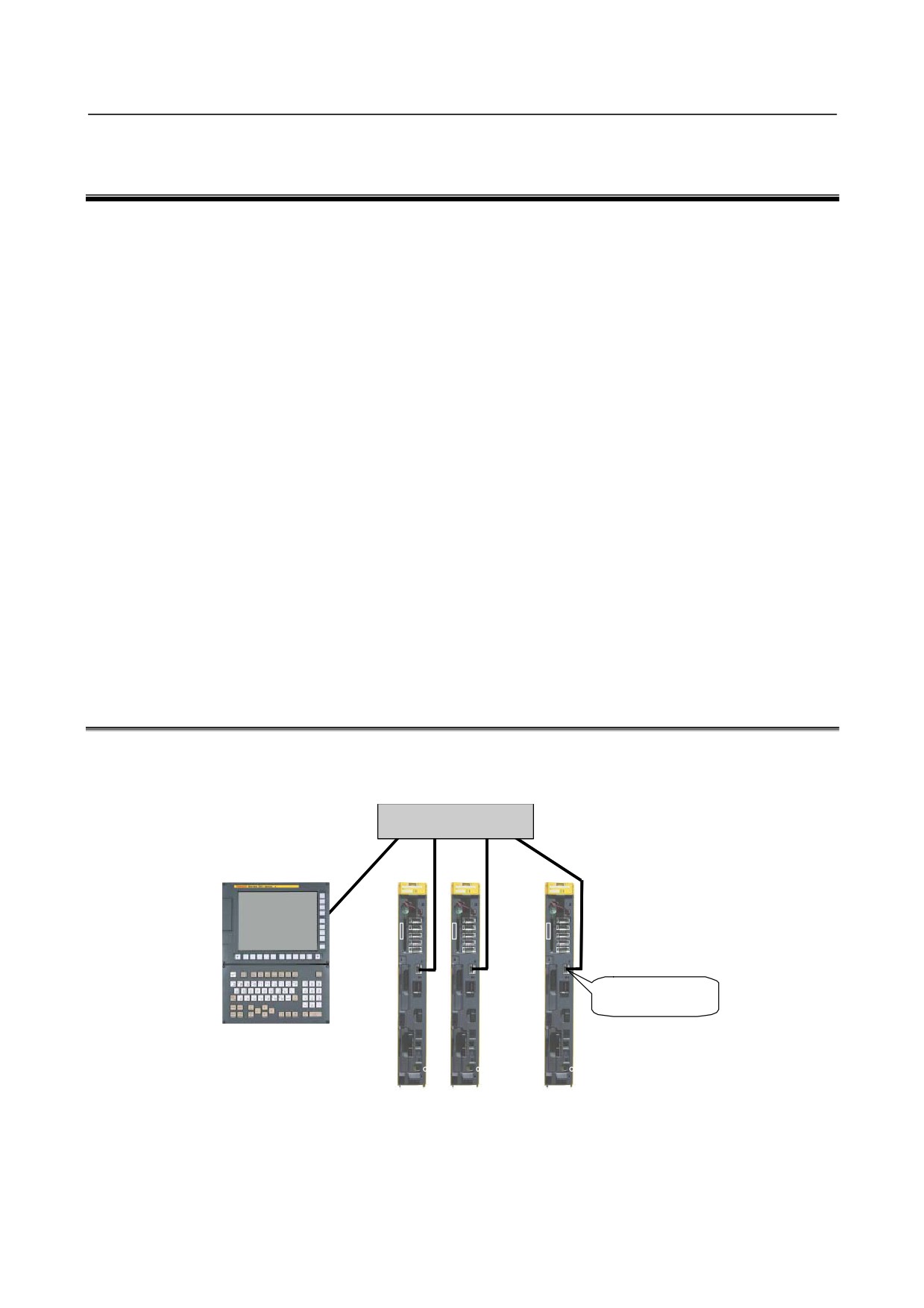
PANEL i
CNC1
CNC2
CNC3
CNC4
CNC5
(192.168.1.200)
(192.168.1.10) (192.168.1.11) (192.168.1.12) (192.168.1.13) (192.168.1.14)
Fig. H.2 (a)
The software option required for this configuration is indicated below.
1
Ethernet Display function (-R950)
2
CNC Screen Display function (A02B-0207-J858)
- 788 -
B-64485EN/01
APPENDIX H.ETHERNET DISPLAY FUNCTION
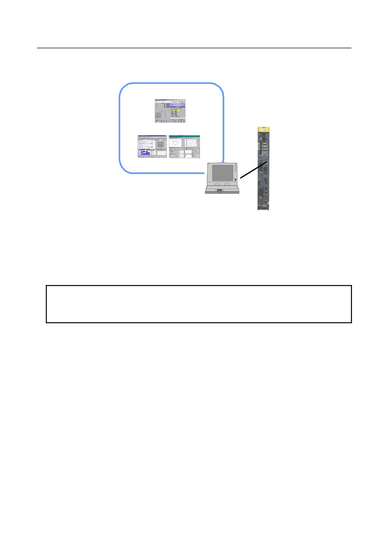
Example 2: When no display unit is required
No display unit is required usually. However, a notebook personal computer is connected as a display unit
to a CNC for maintenance.
CNC screen display and operation
(temporary connection)
CNCScrnE
M
LADDER-III SERVO GUIDE
Notebook PC
CNC
(192.168.1.200)
(192.168.1.10)
Fig. H.2 (b)
The software option required for this configuration is indicated below.
1
Ethernet Display function (-R950)
2
CNC Screen Display function (A02B-0207-J858)
NOTE
When a personal computer and CNC are connected with each other on a
one-to-one basis, the optional Ethernet Display function may not be selected. In
this case, the node number is fixed at "0" (IP address: 192.168.1.10).
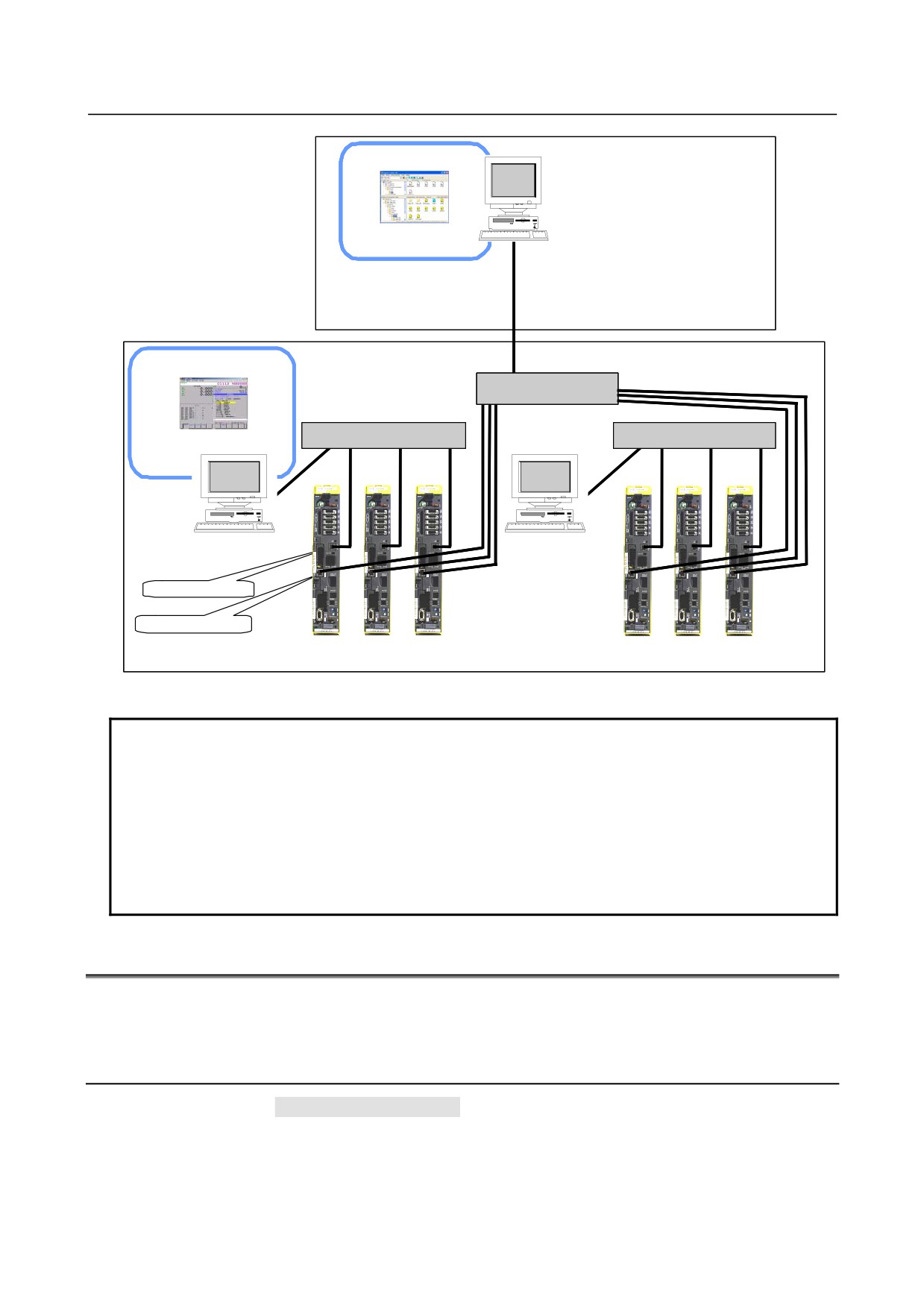
Example 3: When a connection is made with a factory network
Personal computer 1 is connected to hub 1 as a display unit for CNC1, CNC2, and CNC3. Personal
computer 2 is connected to hub 2 as a display unit for CNC4, CNC5, and CNC6. To communicate with
personal computer 3 on the factory network, a Fast Ethernet board is added to each CNC, and personal
computer 3 and all CNCs are connected to hub 3.
- 789 -
H.ETHERNET DISPLAY FUNCTION APPENDIX
B-64485EN/01
Office
PC 3
(192.168.2.100)
Program Transfer Tool
CNC screen display and
Factory
operation
Hub 3
CNCScrnE
Hub 1
Hub 2
CNC1 CNC2
CNC3
CNC4
CNC5 CNC6
PC 1
PC 2
(192.168.1.200)
(192.168.1.200)
Embedded Ethernet
Fast Ethernet board
Embedded Ethernet
(192.168.1.10)
(192.168.1.11)
(192.168.1.12) Embedded Ethernet
(192.168.1.10)
(192.168.1.11)
(192.168.1.12)
Fast Ethernet board
(192.168.2.10)
(192.168.2.11)
(192.168.2.12)
Fast Ethernet board
(192.168.2.20)
(192.168.2.21)
(192.168.2.22)
Fig. H.2 (c)
NOTE
The basic network configuration based on Ethernet Display function consists of
only CNCs and a personal computer for display. If the network has a personal
computer to which CNCs do not communicate, CNC communication processing
load increases, and the display speed can slow down.
So, avoid connecting with the network at the whole factory. However, when a
personal computer is to be connected temporarily for a purpose other than
display, the personal computer can be connected to the network by satisfying the
IP address system above.
H.3 DISPLAY UNIT NUMBER SETTING AND CONFIRMATION
To use Ethernet Display function, set the display unit number to "5" (Sets the display unit for Ethernet
connection) with the rotary switch.
H.3.1 Display Unit Number Setting
Set the rotary switch to "1" (Function number 1) then turn on the power to the CNC. Next, perform the
operation below to set the display unit number.
Function number 1
(1) Check that "1" is blinking on the 7-segment LED then press the push switch.
- 790 -
B-64485EN/01
APPENDIX H.ETHERNET DISPLAY FUNCTION
(2) Each of the sixteen numbers "0" to "F" is displayed on the 7-segment LED at intervals of about one
second. When "5" is displayed, press the push switch.
(3) On the 7-segment LED, "5" blinks.
The display unit numbers are defined as follows:
0
: Not used
1
: Sets the display unit as a display unit connected to
: HSSB or a CNC-dedicated display unit.
2 to 4
: Not used
5
: Sets the display unit for Ethernet connection.
6 to F
: Not used
(4) Press the push switch again. The blinking stops and the display unit number "5" is saved to the CNC.
(5) Set the rotary switch to a proper position according to Appendix H.5, "START SEQUENCE
SWITCHING". Next, turn off the CNC then turn on the CNC again.
CAUTION
Never turn off the power to the CNC until steps (1) through (4) above for display
unit number setting are completed.
H.3.2 Display Unit Number Confirmation
Two methods of confirming the currently set display unit number are available as described below.
Confirming the display unit number at power-on
Set the rotary switch to "4" (Function number 4) then turn on the power to the CNC. Next, perform the
operation below to confirm the display unit number.
Function number 4
(1) Check that "4" is blinking on the 7-segment LED then press the push switch.
(2) Each of the two numbers "0" and "1" is displayed on the 7-segment LED at intervals of about one
second. When "0" is displayed, press the push switch.
(3) On the 7-segment LED, "0" blinks.
(4) Press the push switch again. Each of the three numbers "0" through "2" is displayed on the
7-segment LED at intervals of about one second. When "1" is displayed on the 7-segment LED,
press the push switch.
(5) On the 7-segment LED, "1" blinks.
(6) Press the push switch once more. The blinking stops and the display unit number saved to the CNC
is displayed. Check that the display unit number "5" is set.
(7) Set the rotary switch to a proper position according to Appendix H.5, "START SEQUENCE
SWITCHING". Next, turn off the CNC then turn on the CNC again.
Confirming the display unit number in normal operation
When the CNC is performing normal operation, the display unit number blinks on the 7-segment LED
while the push switch is held down with the rotary switch set to "2".
NOTE
Upon completion of display unit number confirmation, be sure to return the rotary
switch to the previous position.
- 791 -