FANUC Series 30i-MODEL B, 31i-MODEL B, 32i-MODEL B. MAINTENANCE MANUAL - page 25
A.ALARM LIST
APPENDIX
B-64485EN/01
Message
Faulty location/corrective action
Contents
TOO LARGE DATA FOR
Use the [NEXT NET] soft key to
The limit on the net editing screen was
NET-EDITOR
change the net subject to net editing.
exceeded.
TOO MANY FUNCTIONS FOR
Use the [NEXT NET] soft key to
The number of functional instructions
NET-EDITOR
change the net subject to net editing.
exceeded the limit on the net editing
screen.
BAD DIAGRAM STRUCTURE
Check whether the connection shape
The circuit is too complicated to analyze.
of each relay or functional instruction
is correct.
NOT SUPPORT ENHANCED
Replace the functional instruction with
A ladder diagram using an enhanced
LADDER DIAGRAM
a functional instruction supporting an
ladder diagram function contains a
enhanced ladder diagram.
functional instruction which does not
Alternatively, use a net which does
support an enhanced ladder diagram.
not use the enhanced ladder diagram
function.
TOO COMPLICATED CIRCUIT
Connect the circuit to which a branch
The circuit around a functional instruction
AROUND FUNCTION
is made according to the control
is too complicated to analyze.
condition of a functional instruction to
the right bus line without merging it to
the output circuit of the functional
instruction. See X.xx.
CONNECT OUTPUT TO COIL
Connect a coil immediately following
No coil is connected immediately
DIRECTLY
the functional instruction.
following a functional instruction.
SINGLE COIL IS EXPECTED
Only one coil can be connected to
More than one coil is connected to a
this functional instruction.
functional instruction to which only one
coil can be connected.
INVALID CIRCUIT FOR FB
Specify a contact or coil for the
A functional instruction is connected for a
PARAMETER
parameter of the function block.
parameter of a function block.
NO CONNECTION
Connect the broken connection.
The connection is broken.
PARAMETER IS NOT
Set an address.
No address is set to the coil at the input
SUPPLIED
or output section of a function block.
CAN NOT PLACE FB AND
Delete the functional instruction
A functional instruction is placed in the
FUNCTION IN ONE NET
placed in the same net as for the
same net as for a function block.
function block.
NO ASSIGNMENT TO FB
Set a contact.
No contact is set in the input section of
CONTACT
the BOOL type of a function block.
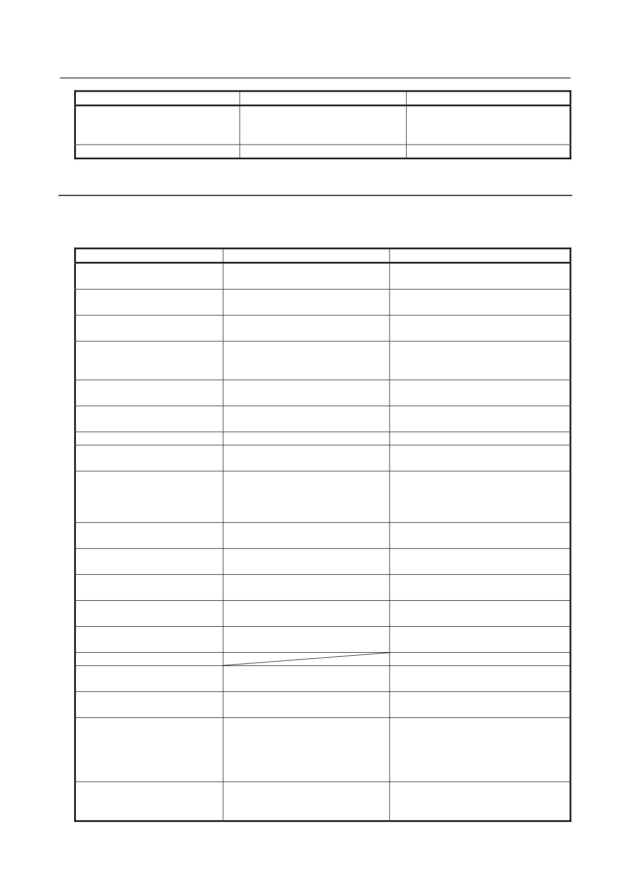
Error messages that may be displayed on the TITLE DATA EDITOR screen
Message
Faulty location/corrective action
Contents
TOO MANY
Make sure that the entered character
The number of characters in the entered
CHARACTERS
string is within the allowable input
character string exceeds the allowable input
length.
length. Some of the characters are
discarded.
PROGRAM IS BEING
Disconnect the online communication
The title data cannot be displayed because
MODIFIED
with FANUC LADDER-III. Stop other
online communication with FANUC
applications from accessing the title
LADDER-III is in progress or another
data.
application is accessing the title data.
THIS FUNCTION IS
Cancel the protection by the
This function is protected by the
PROTECTED
programmer protection function or
programmer protection function or 8-level
8-level protection function.
protection function.
- 702 -
B-64485EN/01
APPENDIX
A.ALARM LIST
Error messages that may be displayed on the SYMBOL & COMMENT DATA
EDITOR screen
Message
Faulty location/corrective action
Contents
TOO MANY
Make sure that the entered address is
The number of characters in the entered
CHARACTERS
within the allowable input length.
address exceeds the allowable address
input length.
ADDRESS IS REQUIRED
Enter an address correctly.
No address was entered during the batch
input of address, symbol, and comment data
using the SYMBOL & COMMENT EDITOR
screen.
ILLEGAL PMC ADDRESS
Enter an address correctly.
The specified address is invalid, or the
entered address character string contains a
space or spaces.
THE ADDRESS ALREADY
Specify another address.
An already registered address was entered.
HAS AN ENTRY
THE SYMBOL NAME IS
Specify another symbol.
An already registered symbol was entered.
ALREADY USED
PMC ADDRESS MUST BE
Enter a PMC address in the ADDRESS
No PMC address was entered when new
ENTERED
field.
symbol/comment data is registered.
TOO LONG SYMBOL
Make sure that the symbol consists of
The entered symbol exceeds the specified
NAME
16 characters or less.
number of characters.
TOO LONG COMMENT
Make sure that the comment consists of
The entered comment exceeds the specified
STRING
30 characters or less.
number of characters.
BAD SYMBOL NAME
Define a symbol that contains no space.
The entered symbol contains a space or
spaces.
THE STRING IS NOT
Specify another character string for the
The search was done for the specified
FOUND
search.
character string but did not find it.
OUT OF SPACE
Create free space for the sequence
The symbol/comment editing area has no
program, by deleting unnecessary
free space.
ladder or message data.
PROGRAM IS BEING
Disconnect the online communication
The symbol/comment data cannot be
MODIFIED
with FANUC LADDER-III. Stop other
displayed because online communication
applications from accessing the
with FANUC LADDER-III is in progress or
symbol/comment data.
another application is accessing the
symbol/comment data.
THIS FUNCTION IS
Cancel the protection by the
This function is protected by the
PROTECTED
programmer protection function or
programmer protection function or 8-level
8-level protection function.
protection function.
BAD SYMBOL NAME
Change the symbol name.
The symbol name is invalid.
CANNOT EDIT ADDRESS
Use FANUC LADDER-III to change the
The symbol whose PMC address is
AUTO ASSIGNED
symbol.
assigned automatically by compiling FANUC
SYMBOL
LADDER-III, can not edit.
ILLEGAL DATA TYPE
Enter a correct data type.
The specified data type is invalid.
ILLEGAL PROGRAM
Enter a correct program name.
The specified program is invalid.
NAME
LINE FEED IS NOT
Line feed code can be entered in
Line feed code cannot be entered in this
AVAILABLE IN THIS DATA
comment data only. Do not enter it in
data.
other data.
LINE FEED IS NOT
Enter Line feed code in the insert or
Line feed code cannot be entered in this
AVAILABLE IN THIS
overwrite mode.
mode.
MODE
NO SYMBOL. PROGRAM
Symbol name is required for local
The specified program is ignored because
SETTING IS IGNORED
symbol.
no symbol is specified.
NOTHING TO PASTE
You need to copy or cut character
You try to paste character strings without
strings before you paste them.
copying or cutting ones.
TOO LARGE DATA TO
Shorten the character string to copy or
The character strings is too long to copy or
PASTE
cut.
cut.
- 703 -
A.ALARM LIST
APPENDIX
B-64485EN/01
Message
Faulty location/corrective action
Contents
UNAVAILABLE
Do not copy or cut characters which
The characters which can not be used at
CHARACTERS WAS
cannot be used at pasted position.
pasted position, were omitted.
OMITTED.
Error messages that may be displayed on the MESSAGE DATA EDITOR
screen
Message
Faulty location/corrective action
Contents
INPUT INVALID
Enter ";" in the 5th digit position in the
The format of message number is
batch message input process.
missing. The delimiter code - semicolon
(;) - was not entered in the batch
message input process.
ILLEGAL NUMBER
Enter a four-digit number as the
The entered message number contains
message number.
any nonnumeric character, or a number
shorter than four digits was entered.
THE NUMBER IS OUT OF
Make sure that the entered message
The entered message number is out of
RANGE
number with path number is in the
range.
range between 1000 and 4095.
Another message number is in the
range between 1000 and 9999.
CLOSING "@" IS NOT FOUND
When entering kana or other
One of the @ sign pair is missing.
Japanese characters, make sure that
they are enclosed within a pair of @
signs.
BAD NUMBER OF
Enter a character string correctly
The number of characters entered
CHARACTERS IN "@-@"
between a pair of @ signs.
between the pair of @ signs is not even.
ILLEGAL CHARACTER IN
Enter a character string correctly
One or more invalid character codes
"@-@"
between a pair of @ signs.
exist between the pair of @ signs.
BAD NUMBER OF
Enter a two-byte code correctly
The number of characters in the two-byte
CHARACTERS FOR 2-BYTE
between @02 and 01@.
code (characters entered between @02
CODE
and 01@) is not a multiple of four.
ILLEGAL 2-BYTE CODE
Enter a two-byte code correctly
The two-byte code (characters entered
between @02 and 01@.
between @02 and 01@) contains one or
more characters other than the JIS
codes.
CLOSING CONTROL CODE
Enter the closing control code.
The two-byte code (characters entered
"01" IS NOT FOUND
between @02 and 01@) lacks the
closing control code (01).
CONTROL CODE "XX" IS
Remove any repeated control code.
The starting control code (02), closing
REPEATED
control code (01), and/or umlaut code
(0D) is repeated.
CLOSING "]" IS NOT FOUND
Make sure that the "[" and "]" codes
The delimiter codes for numerical data
are entered in pairs.
are not entered in pairs.
BAD NUMERICAL DATA
Specify the numerical data correctly.
The format of the numerical data is
FORMAT
invalid.
BAD PMC ADDRESS FOR
Enter an available address.
The address section of the numerical
NUMERIAL DATA
data is invalid.
PROGRAM IS BEING
Disconnect the online communication
The message data cannot be displayed
MODIFIED
with FANUC LADDER-III. Stop other
because online communication with
applications from accessing the
FANUC LADDER-III is in progress or
message data.
another application is accessing the
message data.
THIS FUNCTION IS
Cancel the protection by the
This function is protected by the
PROTECTED
programmer protection function or
programmer protection function or 8-level
8-level protection function.
protection function.
- 704 -
B-64485EN/01
APPENDIX
A.ALARM LIST
Error messages that may be displayed on the I/O MODULE EDITOR screen
Message
Faulty location/corrective action
Contents
GROUP NUMBER IS TOO
Specify 15 or a smaller value as the
The entered group number is too large.
LARGE
group number.
BASE NUMBER IS TOO LARGE
Specify base number 0 for I/O Unit-B
The entered base number is too large.
(##, #1 - #10).
SLOT NUMBER IS TOO LARGE
Specify 30 or a smaller value as the
The entered slot number is too large.
slot number for I/O Unit-B (##, #1 -
#10).
For other I/O units, specify 10 or a
smaller value.
SLOT NUMBER IS TOO SMALL
Check the I/O unit name.
The entered slot number is too small.
I/O UNIT NAME MISMATCH
Check the I/O unit name or address.
The input I/O unit is assigned to the Y
address, or the output I/O unit is
assigned to the X address.
ILLEGAL I/O UNIT NAME
Enter an I/O unit that is listed in Tables
The entered I/O unit name is invalid.
3.2 (a) to 3.2 (c) in Chapter 3.
NOT ENOUGH SPACE
Enter the data again after creating free
There is not enough free address space
space by deleting the data allocated
for the size of the I/O unit you are going
behind the current cursor position or by
to assign.
other adequate means.
This error also occurs if you attempt to
assign the I/O unit to an already
allocated address space.
PROGRAM IS BEING
Disconnect the online communication
The I/O module data cannot be
MODIFIED
with FANUC LADDER-III. Stop other
displayed because online
applications from accessing the I/O
communication with FANUC
module data.
LADDER-III is in progress or another
application is accessing the I/O module
data.
THIS FUNCTION IS
Cancel the protection by the
This function is protected by the
PROTECTED
programmer protection function or
programmer protection function or
8-level protection function.
8-level protection function.
Error messages that may be displayed on the I/O CONFIGURATION EDITOR
(I/O Link i assignment) screen
Message
Faulty location / corrective action
Contents
TOO MANY GROUPS (CHx)
Delete any unnecessary group, then
A new group cannot be created
create a new group.
because the maximum number of
groups per channel is exceeded.
TOO MANY SLOTS (CHx)
Delete any unnecessary slot, then
A new slot cannot be created
create a new slot.
because the maximum number of
slots per channel (256 slots) is
exceeded.
TOO MANY SLOTS IN A GROUP
Delete any unnecessary slot, then
A new slot cannot be created
(CHx, Gyy)
create a new slot.
because the maximum number of
slots per channel (32 slots) is
exceeded.
NO SLOT(Gxx)
Add a slot.
There is no slot in group Gxx.
SLOT NUMBER IS REQUIRED
Enter a slot number.
No slot number is entered for a slot.
SLOT NUMBER DUPLICATE
Change the slot number used more
More than one slot data item having
than once.
the same slot number is found in the
same group.
CAN NOT DELETE MPG SLOT
Turn the MPG flag off in the group
No MPG slot can be deleted in the
setting screen.
slot setting screen.
ILLEGAL SLOT NUMBER
Enter a slot number not greater than
The entered slot number is greater
32.
than 32.
- 705 -
A.ALARM LIST
APPENDIX
B-64485EN/01
Message
Faulty location / corrective action
Contents
ILLEGAL PMC ADDRESS
Enter a correct PMC address again.
The entered PMC address is invalid.
Alternatively, no PMC address is
entered.
ILLEGAL SIZE
Enter a correct size again.
The entered size is outside the PMC
address range.
Alternatively, a value of 0 is entered
as the size.
SLOT HAS NO ASSIGNMENT
Enter a PMC address and size.
For a slot, a PMC address or size is
not entered for both DI and DO.
ILLEGAL COMMENT
Enter a correct comment again.
An entered comment does not
conform to the extended symbol and
comment format.
PMC ADDRESS OVERLAPPED
Enter the PMC address or size so
Address PMCm X(Y)nnnn is also
(PMCm X(Y)nnnn)
that it is set only once.
assigned to another slot in I/O Link i
assignment data.
TOO MANY OUTPUT POINTS (CHx,
Reduce the number of output points
The number of output points of the
Gyy)
of the group.
I/O Link i group set for Gyy of CHx
exceeds the upper limit (65 bytes by
default or 29 bytes for the safety I/O
device).
TOO MANY INPUT POINTS (CHx,
Reduce the number of input points
The number of input points of the I/O
Gyy)
of the group.
Link i group set for Gyy of CHx
exceeds the upper limit (65 bytes by
default or 29 bytes for the safety I/O
device).
TOO MANY OUTPUT POINTS (CHx)
Reduce the number of output points
Warning message. The number of
in the channel.
I/O Link i output points set in CHx
exceeds the upper limit.
TOO MANY INPUT POINTS (CHx)
Reduce the number of input points
Warning message. The number of
in the channel.
I/O Link i input points set in CHx
exceeds the upper limit.
TOO MANY CHARACTERS
Enter a comment within the input
The number of characters in an
field.
entered comment exceeds the input
width.
THE ADDRESS IS NOT FOUND
The specified address is not found.
INPUT INVALID
Enter a correct numeric value.
A numeric value is invalid.
I/O CONFIG DATA IS BROKEN
Enter an I/O configuration file again.
I/O Link i assignment data is invalid.
TOO MANY SAFETY I/O GROUPS
Reduce the number of I/O Link i
Warning message. More than four
safety I/O groups.
I/O Link i safety I/O groups are
specified either on the PMC or DCS
side in the entire system.
TOO MANY ASSIGNMENTS
When a group in the high-speed
Warning message. In CHn, group yy
(H.SPEED)(CHn,Gyy)
transfer cycle mode is connected to
and following exceed the transfer
I/O Link i, correct assignment so that
capacity limit in transfer timing
the assignment for each group is
assignment processing when the
performed within the quartered
high-speed mode of I/O Link i is
transfer timing with referencing
used.
Subsection 3.6.4 “Transfer Cycle”.
BASIC GROUP INVALID
Correct the number of basic groups
The number of basic groups for the
for the I/O assignment selection
I/O assignment selection function of
function of I/O Link i.
I/O Link i is invalid.
UNAVAILABLE ADDRESS FOR
Use addresses X0/Y0 and following.
Addresses X200/Y200, X400/Y400,
DCSPMC
or X600/Y600 and following are
assigned to a group for which
DCSPMC is specified for the PMC
path.
- 706 -
B-64485EN/01
APPENDIX
A.ALARM LIST
Message
Faulty location / corrective action
Contents
THIS DATA IS BEING MODIFIED
Disconnect the online
I/O configuration data cannot be
communication with FANUC
displayed because online
LADDER-III. Stop other applications
communication with FANUC
from accessing the I/O configuration
LADDER-III is in progress or another
data.
application is accessing the I/O
configuration data.
INTERNAL ERROR(0xCxxxxxxx)
Contact us, and report the displayed
This error occurs due to an internal
message correctly.
factor. An error code is indicated in
parentheses.
Error messages that may be displayed on the SYSTEM PARAMETER screen
Message
Faulty location/corrective action
Contents
INPUT INVALID
Enter a correct numerical value.
The entered numerical value or its input
format is invalid.
SYMBOL UNDEFINED
Enter a defined symbol or bit address.
An undefined symbol character string
was entered.
PROGRAM IS BEING
Disconnect the online communication
The system parameter data cannot be
MODIFIED
with FANUC LADDER-III. Stop other
displayed because online communication
applications from accessing the
with FANUC LADDER-III is in progress
system parameter data.
or another application is accessing the
system parameter data.
THIS FUNCTION IS
Cancel the protection by the
This function is protected by the
PROTECTED
programmer protection function or
programmer protection function or 8-level
8-level protection function.
protection function.
Error messages that may be displayed on the SIGNAL STATUS screen
Message
Faulty location/corrective action
Contents
INPUT INVALID
Enter a correct numerical value.
The entered numerical value or its input
format is invalid.
SYMBOL UNDEFINED
Enter a defined symbol or bit address.
An undefined symbol character string
was entered.
THIS FUNCTION IS
Cancel the protection by the
This function is protected by the
PROTECTED
programmer protection function or
programmer protection function or 8-level
8-level protection function.
protection function.
Error messages that may be displayed on the PMC PARAM screen
Message
Faulty location/corrective action
Contents
INPUT INVALID
Enter a numerical value correctly.
The entered numerical value or its input
format is invalid.
MUST BE IN EMERGENCY
Set a mode to MDI or emergency
The status of NC is not MDI mode or
STOP OR IN MDI MODE
stop.
emergency stop.
PWE MUST BE ON
Set the “PWE” to ”1” in NC setting
The “PWE” in NC setting screen is ”0”.
screen.
EITHER PWE OR KEY4 MUST
Set the “PWE” to ”1” in NC setting
The “PWE” in NC setting screen is ”0” or
BE ON
screen or set the key “KEY4” to “1”.
the program protect key “KEY4” is ”0”.
THIS FUNCTION IS
Cancel the protection by the
This function is protected by the
PROTECTED
programmer protection function or
programmer protection function or 8-level
8-level protection function.
protection function.
Error messages that may be displayed on the SIGNAL TRACE screen
Message
Faulty location/corrective action
Contents
TRACE FUNCTION IS
Wait until FANUC LADDER-III or
FANUC LADDER-III or some other
ALREADY IN USE.
some other application finishes using
application is currently using the trace
the trace function before executing it.
function.
- 707 -
A.ALARM LIST
APPENDIX
B-64485EN/01
Message
Faulty location/corrective action
Contents
NO SAMPLING ADDRESS.
Specify a bit address as a sampling
No sampling address is specified in the
address in the trace parameter.
trace parameter.
NO STOP TRIGGER ADDRESS.
Specify a bit address as the stop
The stop trigger address is not specified
trigger address in the trace
in the trace parameter.
parameter.
NO SAMPLING TRIGGER
Specify a bit address as the sampling
The sampling trigger address is not
ADDRESS.
trigger address in the trace
specified in the trace parameter.
parameter.
USB MEMORY IS USED BY
Terminate another function that is
The USB memory is being used by
OTHER FUNCTION.
using the USB memory, then perform
another function.
operation again.
USB MEMORY IS NOT READY.
Check whether a USB memory is
No USB memory is inserted.
inserted.
USB MEMORY IS FULL.
Delete any unnecessary files and
The USB memory is full.
allocate a required capacity.
USB MEMORY HAS BEEN
Insert the USB memory, then execute
A USB memory is removed while it is
REMOVED
input/output operation again.
being accessed.
USB MEMORY IS NOT
Replace the USB memory with
The inserted USB memory cannot be
FORMATTED
another one.
recognized.
USB HARDWARE ERROR
Replace the USB memory with
This error occurs due to a USB hardware
(xxxxxxxxxx)
another one. If this error still occurs
failure. An error code is indicated in
after replacement, contact us, and
parentheses.
report the displayed message
correctly.
INTERNAL ERROR (xxxxxxxxxx)
Contact us, and report the displayed
This error occurs due to an internal
message correctly.
factor.
An error code is indicated in
parentheses.
Error messages that may be displayed on the trace setting screen
Message
Faulty location/corrective action
Contents
INPUT INVALID
Enter a numerical value that is within
A nonnumeric value or an out-of-range
the specified data range of the
parameter value was entered.
relevant trace parameter.
SYMBOL UNDEFINED
Enter a defined symbol or bit address.
An undefined symbol character string
was entered.
BIT ADDRESS IS REQUIRED
Specify a bit address as the stop or
A byte address was specified as the stop
sampling trigger address.
or sampling trigger address.
INVALID STOP TRIGGER
Enter a PMC signal address that can
The bit address entered as the stop
ADDRESS
be used as the stop trigger address.
trigger address is invalid.
INVALID SAMPLING TRIGGER
Enter a PMC signal address that can
The bit address entered as the sampling
ADDRESS
be used as the sampling trigger
trigger address is invalid.
address.
UNSUPPORTED TRACE
This file cannot be handled. Set data
An attempt was made to read a trace
SETTING FILE
in the TRACE SETING screen.
setting file that could not be handled.
INVALID SETTING VALUE
Output the trance setting file again.
An invalid setting is found.
(LINE n)
Alternatively, set data in the TRACE
The file may be damaged.
SETING screen.
SAMPLING TIME/FRAME WAS
Check the data on the TRACE
The values are adjusted according to the
ADJUSTED
SETING screen.
read data. (This is warning.)
UNKNOWN SETTING WAS
Check the read trace data.
An unknown trace setting item is found
SKIPPED(LINE n)
and ignored.
(This is warning.)
INVALID SAMPLING ADDRESS
Check the read trace data.
An invalid sampling address is found.
WAS FOUND
(This is warning.)
- 708 -
B-64485EN/01
APPENDIX
A.ALARM LIST
Message
Faulty location/corrective action
Contents
TOO MANY SAMPLING
Check the read trace data.
The number of sampling addresses
ADDRESSES
exceeds the upper limit. (This is
warning.)
THE FILE IS NOT TRACE
This file cannot be read. Specify a
An attempt was made to read a file which
SETTING FILE
correct file.
was not a trace setting file.
FILE NAME CONTAINS
Correct file name.
“FORFANUC” cannot be used in the top
RESERVED WORD.
of the file name.
USB MEMORY IS USED BY
Terminate another function that is
The USB memory is being used by
OTHER FUNCTION.
using the USB memory, then perform
another function.
operation again.
Another function is formatting the USB
memory.
USB MEMORY IS NOT READY.
Check whether a USB memory is
No USB memory is inserted.
inserted.
USB MEMORY HAS BEEN
Insert the USB memory, then execute
A USB memory is removed while it is
REMOVED
input/output operation again.
being accessed.
USB MEMORY IS NOT
Replace the USB memory with
The inserted USB memory cannot be
FORMATTED
another one.
recognized.
FILE NAME IS INVALID.
Correct the file name.
An invalid character is found in a file
name.
FOLDER NAME CANNOT BE
A folder name is specified. Specify an
An attempt was made to read or write a
SPECIFIED.
appropriate file name.
folder.
USB HARDWARE ERROR
Replace the USB memory with
This error occurs due to a USB hardware
(xxxxxxxxxx)
another one. If this error still occurs
failure. An error code is indicated in
after replacement, contact the
parentheses.
FANUC service center, and report the
displayed message correctly.
INTERNAL ERROR (xxxxxxxxxx)
Contact us, and report the displayed
This error occurs due to an internal
message correctly.
factor.
An error code is indicated in
parentheses.
Error messages that may be displayed on the I/O diagnosis screen
Message
Faulty location/corrective action
Contents
ENTER STRING TO SEARCH.
Enter a string before starting a
No search string is specified.
search.
I/O DIAGNOSIS FUNCTION IS
To use the I/O diagnosis function,
The I/O diagnosis function cannot
NOT SUPPORTED
update the PMC system software.
be used because the PMC system
software is an older version.
INPUT INVALID
Check the entered string.
The entered string is invalid.
LADDER PROGRAM IS BROKEN
Check the information displayed on
The program is corrupted.
the PMC alarm screen and reload
the program.
NO GROUP FORMAT.
Use [GROUP] on the I/O diagnosis
No group display is set.
(setting) screen.
PROGRAM IS BEING MODIFIED.
Retry after completing the function
The program cannot be referenced
that is using the program.
because it is being used by another
function.
REACHED TO THE END OF
To make another search, specify a
The search has been completed
SYMBOL DATA.
string again.
until the end of the data has been
reached.
SYMBOL ORDER IS NOT
Use the FANUC LADDER-III to
The format of this program does not
AVAILABLE.
convert the program to one with an
allow sorting and display in symbol
expanded function.
order.
THE GROUP IS NOT FOUND
Check the specified group.
The specified group is not found.
- 709 -
A.ALARM LIST
APPENDIX
B-64485EN/01
Message
Faulty location/corrective action
Contents
FORCING IS PROTECTED ON
Disable the programmer protection
The forced input/output function is
THIS PATH.
function.
currently protected on the selected
PMC path.
THE STRING IS NOT FOUND
Check the specified string.
The specified string is not found.
A.2.4 I/O Communication Error Messages
The error messages that may appear on the I/O screen and their meanings and actions are listed below.
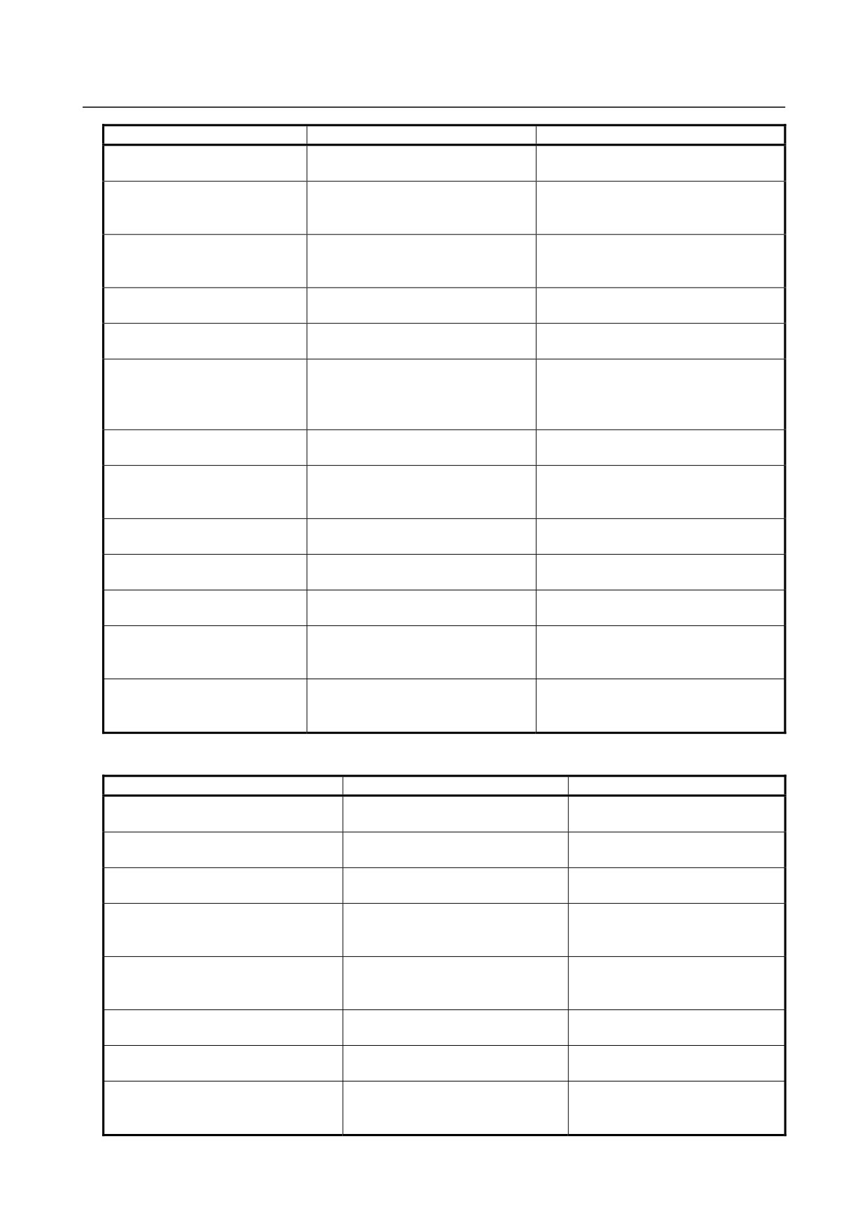
Error messages displayed during memory card I/O operation
Message
Faulty location/corrective action
Contents
MEMORY CARD IS NOT
Check whether a memory card is
No memory card is installed.
READY
installed.
MEMORYCARD IS FULL
Delete files to create available space.
There is no available space in the
memory card.
MEMORYCARD IS WRITE
Release the write protection of the
The memory card is write-protected.
PROTECTED
memory card.
MEMORYCARD IS NOT
Format the memory card in FAT16. (It
The memory card cannot be recognized.
FORMATTED
cannot be recognized if formatted in
FAT32.)
TOO MANY FILES IN
Delete unnecessary files to reduce
There are too many files.
MEMORYCARD
the number of files.
FILE NOT FOUND
On the list screen, check the file
The specified file cannot be found.
name or file number.
FILE IS READ-ONLY
Check the attributes of the file.
Write to the specified file is not permitted.
FILE NAME IS INVALID
Specify the file name in MS-DOS
The file name is illegal.
form.
COULD NOT FORMAT
The NC cannot format this memory
The memory card cannot be formatted.
MEMORY CARD
card. Format the memory card in
FAT16 using another PC. (It cannot
be recognized if formatted in FAT32.)
UNSUPPORTED
Replace the memory card with
This memory card is not supported.
MEMORYCARD
another one.
CAN NOT DELETE FILE
Check the attributes of the file.
An error occurred when a file was
deleted from the memory card.
MEMORYCARD BATTERY
Replace the battery of the memory
The battery of the memory card has
ALARM
card.
become weak.
THIS FILE NAME IS ALREADY
Change the file name to another one.
The file name is already used.
USED
MEMORYCARD ACCESS
Replace the memory card with
The memory card cannot be accessed.
ERROR
another one.
DIFFERENCE FOUND
File comparison detected a mismatch.
MEMORY CARD IS LOCKED BY
Wait until the PMC user completes
Another PMC user is using the memory
OTHER FUNCTION
processing, then retry.
card.
MEMORY CARD HEADER ROM
This file cannot be read. Check the
An attempt was made to read a file, but
DATA ID IS ILLEGAL
type of the file.
its ROM data ID was illegal.
FILE NUMBER CAN NOT
If the file does not exist, the key entry
The file number cannot be selected.
SELECTED
is invalid. If this error occurs even
when the cursor is placed at a file
name, contact the FANUC service
center.
THE FILE NUMBER DOES NOT
Check the total number of files on the
The entered file number is not present.
EXIST
list screen.
The entered number exceeds the total
number of files.
- 710 -
B-64485EN/01
APPENDIX
A.ALARM LIST
Message
Faulty location/corrective action
Contents
FILE NUMBER IS RESTRICTED
Enter a numeric value not exceeding
A value up to 128 can be entered as the
TO "128"
128.
file number.
MEMORY CARD IS USED BY
Retry after terminating the other
Some other function is currently using
OTHER FUNCTION
function that is currently using the
the memory card.
memory card.
MEMORY CARD IS WRITE
Cancel the write protection of the
The memory card is write protected.
PROTECTED
memory card, or use another memory
card that is not write protected.
UNSUPPORTED MEMORY
Use another memory card.
This is an unsupported type of memory
CARD
card.
COULD NOT DELETE FILE
Check the read/write permission
The file cannot be deleted.
attribute of the file.
TRACE FILE NUMBER IS OVER
Delete unnecessary old trace result
No more trace result file can be created
file or files.
because the maximum trace result file
number (file extension) has been
reached.
UNSUPPORTED TRACE
This file cannot be handled. Set data
An attempt was made to read a trace
SETTING FILE
in the TRACE SETING screen.
setting file that could not be handled.
INVALID SETTING VALUE
Output the trance setting file again.
An invalid setting is found.
(LINE n)
Alternatively, set data in the TRACE
The file may be damaged.
SETING screen.
SAMPLING TIME/FRAME WAS
Check the data on the TRACE
The values are adjusted according to the
ADJUSTED
SETING screen.
read data. (This is warning.)
UNKNOWN SETTING WAS
Check the read trace data.
An unknown trace setting item is found
SKIPPED(LINE n)
and ignored. (This is warning.)
INVALID SAMPLING ADDRESS
Check the read trace data.
An invalid sampling address is found.
WAS FOUND
(This is warning.)
TOO MANY SAMPLING
Check the read trace data.
The number of sampling addresses
ADDRESSES
exceeds the upper limit. (This is
warning.)
INTERNAL ERROR (xxxxxxxxxx)
Contact the FANUC service center,
An error due to an internal factor
and report the displayed message
occurred. Details on the error are
correctly.
displayed in parentheses.
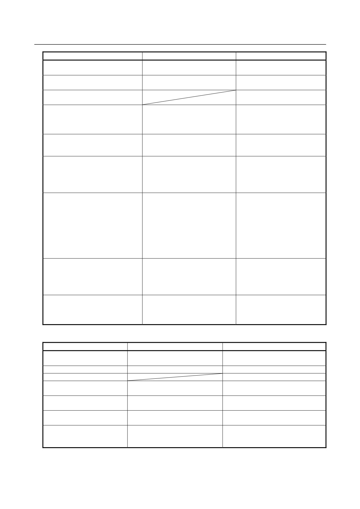
Error messages displayed during USB memory I/O operation
Message
Faulty location/corrective action
Contents
FILE NAME CONTAINS RESERVED
Correct file name.
“FORFANUC” cannot be used in
WORD.
the top of the file name.
USB MEMORY HAS BEEN REMOVED
Insert the USB memory, then
A USB memory is removed while it
execute input/output operation again.
is being accessed.
USB MEMORY IS NOT READY.
Check whether a USB memory is
No USB memory is inserted.
inserted.
USB MEMORY IS USED BY OTHER
Terminate another function that is
The USB memory is being used by
FUNCTION.
using the USB memory, then perform
another function.
operation again.
THIS FILE NAME IS ALREADY USED.
Follow the message, and overwrite
An existing file name is specified as
OVERWRITE IT?
the file or specify another file name
the write destination.
to write data.
FILE NOT FOUND
Check the file name or number on
The specified file is not found.
the file list screen.
USB MEMORY IS FULL.
Delete any unnecessary files and
The USB memory is full.
allocate a required capacity.
FILE IS READ-ONLY.
Specify another file or check the file
The specified file is read-only.
attribute and delete the read-only
attribute.
- 711 -
A.ALARM LIST
APPENDIX
B-64485EN/01
Message
Faulty location/corrective action
Contents
USB MEMORY IS NOT FORMATTED
Replace the USB memory with
The inserted USB memory cannot
another one.
be recognized.
FILE NAME IS INVALID.
Correct the file name.
An invalid character is found in a
file name.
DIFFERENCE FOUND
File comparison detected a
mismatch.
THE FILE NUMBER DOES NOT
Check the total number of files on
The entered file number is not
EXIST
the list screen.
found. The entered number is
greater than the total number of
files.
FILE NUMBER IS RESTRICTED TO
Enter a numeric value not greater
A value up to 128 can be entered
"128"
than 128.
as the file number.
FOLDER CANNOT BE SPECIFIED.
<1> The specified number indicates
<1> The specified number indicates
a folder. Enter an appropriate
a folder.
number.
<2> An attempt was made to select
<2> No folder can be selected in the
a folder in the file list screen.
file list screen.
THIS FILE CANNOT BE SPECIFIED.
<1> The file name corresponding to
<1> The file name corresponding to
the specified file number
the specified file number
consists of more than 32
consists of more than 32
characters. Enter an appropriate
characters.
number.
<2> An attempt was made to select
<2> No file having a file name
a file having a file name
consisting of more than 32
consisting of more than 32
characters can be selected in
characters.
the file list screen.
USB HARDWARE ERROR
Replace the USB memory with
This error occurs due to a USB
(xxxxxxxxxx)
another one. If this error still occurs
hardware failure. An error code is
after replacement, contact the
indicated in parentheses.
FANUC service center, and report
the displayed message correctly.
INTERNAL ERROR (xxxxxxxxxx)
Contact us, and report the displayed
This error occurs due to an internal
message correctly.
factor.
An error code is indicated in
parentheses.
Error messages displayed during flash ROM I/O operation
Message
Faulty location/corrective action
Contents
NOT IN EMG STOP MODE
Place the system in the emergency
The system is not in the emergency stop
stop state.
state.
INVALID LADDER PROGRAM
Check the program.
The transfer program is illegal.
DIFFERENCE FOUND
A file comparison detected a mismatch.
FLASH ROM IS LOCKED BY
Wait until the PMC user completes
Another PMC user is using the flash
OTHER FUNCTION
processing, then retry.
ROM.
FLASH ROM HEADER ROM
This file cannot be read. Check the
An attempt was made to read a file, but
DATA ID IS ILLEGAL
type of the file.
its ROM data ID was illegal.
FLASH ROM IS USED BY
This file cannot be read. Check the
The ROM data ID of the file you
OTHER FUNCTION
type of the file.
attempted to read is invalid.
INTERNAL ERROR (xxxxxxxxxx)
Contact the FANUC service center,
An error due to an internal factor
and report the displayed message
occurred. Details on the error are
correctly.
displayed in parentheses.
- 712 -
B-64485EN/01
APPENDIX
A.ALARM LIST
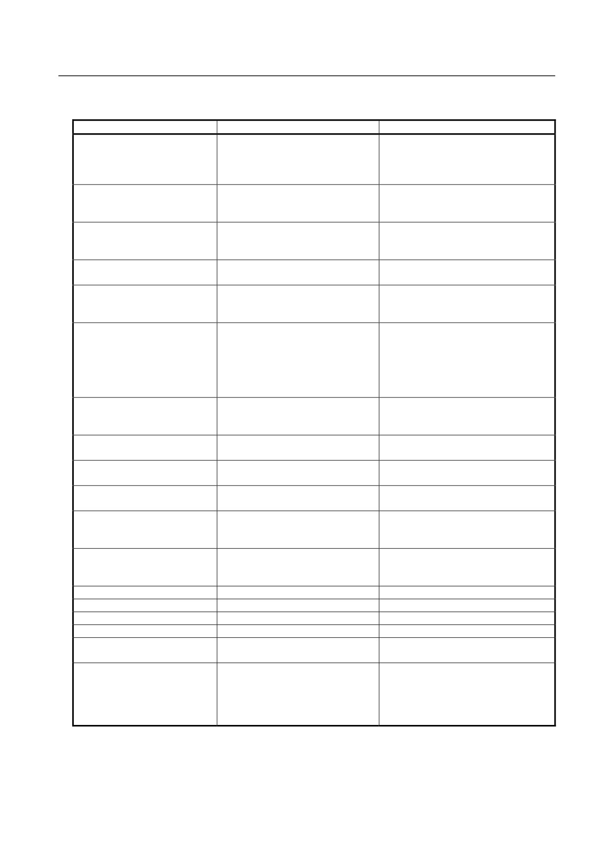
Error messages displayed during FLOPPY or other input/output device I/O
operation
Message
Faulty location/corrective action
Contents
ILLEGAL PMC PARAMETER
Specify a file of the PMC parameter
The specified file is not of the PMC
FORMAT
format. Also, check the specified file
parameter format.
to see whether its content is not
disrupted.
ILLEGAL HANDY FILE FORMAT
Specify a file of the handy file format.
The specified file is not of the handy file
Also, check the specified file to see
format.
whether its content is not disrupted.
UNKNOWN FILE FORMAT
Specify file of recognizable format
Can not recognize the format of specified
such as PMC parameter format, or
file.
check the contents of the file.
FILE NAME OR FILE NUMBER
Specify file name or file number for
Need file name or file number to identify
IS REQUIRED
the operation.
file to read, compare, or delete.
COMMUNICATION TIMEOUT
Check the communication
Communication with the I/O device has
parameters such as baud rate, and
been timeout.
retry to communicate.
I/O DEVICE IS NOT ATTACHED
Check the power of I/O device is ON.
Any I/O device is not connected, or some
OR IN ERROR STATUS
Check the I/O device is connected.
error has occurred in it.
Check the cable that connects I/O
device with PMC is correct one. If
some error has occurred in I/O
device, solve it.
RECEIVED BAD DATA: CHECK
Check the PMC's communication
Invalid data has been received.
THE COMMUNICATION
parameters such as baud rate match
PARAMETERS
the ones of I/O device.
RECEIVED DATA HAS
Check the communication
Too many data have received at once.
OVERRUN
parameters about flow control.
OTHERS FUNCTION IS USING
Use the other channel, or stop the
Others function is using this channel.
THIS CHANNEL
function.
BAD COMMUNICATION
Check the communication
Setting parameters of communication are
PARAMETER
parameters such as baud rate.
not correct.
OTHER FUNCTION IS USING
Wait until function that using I/O
Another function such as FANUC
I/O FUNCTION
function do finish, or stop the
LADDER-III is using I/O function.
function.
UNKNOWN HANDY FILE
Check the file.
The received data is not a program of the
FORMAT DATA
PMC system or is a program of some
other incompatible type.
ILLEGAL BAUD RATE SETTING
Set a valid baud rate.
The set baud rate is invalid.
ILLEGAL CHANNEL NUMBER
Set a valid channel number.
The set channel number is invalid.
ILLEGAL PARITY BIT SETTING
Set a valid parity bit.
The set parity bit is invalid.
ILLEGAL STOP BIT SETTING
Set a valid stop bit.
The set stop bit is invalid.
ILLEGAL WRITE CODE
Set a valid output code.
The set output code is invalid.
SETTING
SEQUENCE PROGRAM IS IN
Wait until On-line function, do finish
Can not input/output of sequence
USE BY ONLINE FUNCTION
the using I/O function. In general,
program, because On-line function is
both of I/O function and On-line
using sequence program.
function should not be used at the
same time.
- 713 -
A.ALARM LIST
APPENDIX
B-64485EN/01
Common error messages that may be displayed on individual devices during
the I/O operations
Alarm number
Faulty location/corrective action
Contents
ERROR OCCURS IN LADDER
Check the PMC alarm screen and
Data cannot be output because there is
PROGRAM
correct the indicated program error
an error in the ladder program.
accordingly.
UNKNOWN DATA TYPE
Check the file.
The PMC type of the input data is
unknown.
MUST BE IN EMERGENCY
Set the NC to the emergency stop
The NC is not in the emergency stop
STOP
state.
state when the PMC parameter is read.
PWE MUST BE ON
Set PWE to 1 on the NC setting
PWE on the NC setting screen is 0
screen.
during reading from the PMC parameter.
MUST BE IN EDIT MODE
Set the NC to the EDIT mode.
The NC is not in the EDIT mode during
writing to the PMC parameter.
THIS FUNCTION IS NOT
Release the protection by the
Protection is made by the programmer
ALLOWED
programmer protection function or
protection function or 8-level protection
8-level protection function.
function.
PMC PARAMETER IS LOCKED
Retry after terminating the other
The PMC parameter is currently used by
BY OTHER FUNCTION
function that is currently using the
some other function and cannot be
PMC parameter.
referenced by this function.
THIS DEVICE IS USED BY
Retry after terminating the other
The specified device is currently used by
OTHER FUNCTION
function that is currently using the
some other function and cannot be used
specified device.
by this function.
PMC PARAMETER IS
Retry after terminating the other
The PMC parameter is currently used by
PROTECTED BY OTHER
function that is currently using the
some other function and cannot be
FUNCTION
PMC parameter.
changed by this function.
LADDER TYPE UNMATCH
Specify a program of a valid type.
The specified program is of a different
type and cannot be read.
TOO LARGE SEQUENCE
Check the file. Or, change to a step
The ladder program is too large to read.
PROGRAM
number option that allows you to set a
larger program size.
SEQUENCE PROGRAM IS
Retry after terminating the other
The ladder program is currently used by
USED BY OTHER FUNCTION
function that is currently displaying
some other function and cannot be
the ladder program.
referenced by this function.
INVALID I/O CONFIGURATION
Read correct I/O configuration file.
Invalid I/O configuration data was read
DATA
and any of the following operations was
performed:
- Writing it to the memory card
- Comparing it with a memory card file
USB
- Writing it to flash ROM
-Comparing it with flash ROM
TOO LARGE I/O
Check the I/O configuration file.
The I/O configuration file is too large to
CONFIGURATION DATA
read.
I/O CONFIGURATION DATA IS
Terminate another function that is
I/O configuration data is being used by
USED BY OTHER FUNCTION
using the I/O configuration data, then
another function (such as FANUC
execute operation again.
LADDER-III).
- 714 -
B-64485EN/01
APPENDIX
A.ALARM LIST
A.3 ALARM LIST (SERIAL SPINDLE)
When a serial spindle alarm occurs, the following number is displayed on the CNC.
NOTE
*1 Note that the meanings of the Spindle Amplifier (SP) indications differ depending
on which LED, the red or yellow LED, is on. When the red LED is on, the Spindle
Amplifier (SP) indicates a 2-digit alarm number. When the yellow LED is on, the
SP indicates an error number that designates a sequence problem (for example,
when a rotation command is entered with the emergency stop state not
released).
See "Error Codes (Serial Spindle)."
*2 For information about serial spindle alarms for numbers that are not listed below,
refer to the following documents according to the actual spindle motor to be
connected.
• FANUC AC SPINDLE MOTOR αi series MAINTENANCE MANUAL
(B-65285EN)
• Technical reports etc.
SP
Number
Message
indication
Faulty location and remedy
Description
(*1)
SP9001
MOTOR
01
1 Check and correct the
The internal temperature of the motor
OVERHEAT
peripheral temperature
exceeds the specified level.
and load status.
The motor is used in excess of the
2 If the cooling fan stops,
continuous rating, or the cooling
replace it.
component is abnormal.
SP9002
EX DEVIATION
02
1 Check and correct the
The motor speed cannot follow a
SPEED
cutting conditions to
specified speed.
decrease the load.
An excessive motor load torque is
2 Correct parameter No.
detected.
4082.
The acceleration/deceleration time
in parameter No. 4082 is
insufficient.
SP9003
DC-LINK FUSE IS
03
1 Replace the Spindle
The Power Supply becomes ready
BROKEN
Amplifier (SP).
(00 is indicated), but the DC link
2 Check the motor
voltage is too low in the Spindle
insulation status.
Amplifier (SP).
The fuse in the DC link section in
SP is blown. (The power device is
damaged or the motor is
ground-fault.)
SP9004
PS IMPROPER
Check the state of the input
The power supply (PS) detected a
INPUT POWER
power supply to the Power
power supply failure. (Power Supply
Supply (PS).
alarm 14)
SP9006
THERMAL
06
1 Check and correct the
The temperature sensor of the
SENSOR
parameter.
motor is disconnected.
DISCONNECT
2 Replace the feedback
cable.
- 715 -
A.ALARM LIST
APPENDIX
B-64485EN/01
SP
Number
Message
indication
Faulty location and remedy
Description
(*1)
SP9007
OVER SPEED
07
Check for a sequence error.
The motor speed has exceeded
(For example, check whether
115% of its rated speed. When the
spindle synchronization was
spindle axis was in position control
specified when the spindle
mode, position error were
could not be turned.)
accumulated excessively (SFR and
SRV were turned off during spindle
synchronization.)
SP9009
OVERHEAT MAIN
09
1
Improve the heat sink
The temperature in the power
CIRCUIT
cooling status.
semiconductor cooling radiator is
2
If the heat sink cooling
abnormally high.
fan stops, replace the
Spindle Amplifier (SP).
SP9010
LOW VOLT INPUT
10
1
Replace the cables.
A drop in the input power voltage in
POWER
2
Replace the SP control
the Spindle Amplifier (SP) is
printed circuit board.
detected.
SP9011
PS OVER VOLT.
1
Check the selected
Overvoltage of the DC link section
DC LINK
Power Supply (PS).
of the Power Supply (PS) was
2
Check the input power
detected. (Power Supply alarm
voltage and change in
indication: 07)
power during motor
PS selection error. (The maximum
deceleration.
output specification of the PS is
If the voltage exceeds
exceeded.)
253 VAC (for the 200-V
system) or 530 VAC (for
the 400-V system),
improve the power
supply impedance.
SP9012
OVERCURRENT
12
1
Check the motor
The motor current is abnormally
POWER CIRCUIT
insulation status.
high.
2
Check the spindle
A motor-specific parameter does
parameters.
not match the motor model.
3
Replace the Spindle
Poor motor insulation
Amplifier (SP).
SP9013
CPU DATA
13
Replace the Spindle Amplifier
Abnormality in a Spindle Amplifier
MEMORY FAULT
(SP) control printed circuit
(SP) control circuit component is
board.
detected. (RAM within the Spindle
Amplifier (SP) is abnormal.)
SP9014
SOFTWARE
14
Replace the spindle software.
A Spindle Amplifier (SP) that is not
SERIES
registered in the spindle software is
MISMATCH
used.
SP9015
SPINDLE
15
1 Check and correct the
The switch sequence in spindle
SWITCHING
ladder sequence.
switching/speed range switching
FAULT
2 Replace the switching
operation is abnormal.
MCC.
The switching MCC contact status
check signal and command do not
match.
SP9016
RAM ERROR
16
Replace the Spindle Amplifier
Abnormality in a Spindle Amplifier
(SP) control printed circuit
(SP) control circuit component is
board.
detected. (RAM for external data is
abnormal.)
SP9017
ID NUMBER
17
Replace the Spindle Amplifier
Abnormality in Spindle Amplifier
PARITY ERROR
(SP)
(SP) ID data is detected.
- 716 -
B-64485EN/01
APPENDIX
A.ALARM LIST
SP
Number
Message
indication
Faulty location and remedy
Description
(*1)
SP9018
SUMCHECK
18
Replace the Spindle Amplifier
Abnormality in a Spindle Amplifier
ERROR
(SP) control printed circuit
(SP) control circuit component is
PROGRAM ROM
board.
detected. (Program ROM data is
abnormal.)
SP9019
EXCESS OFFSET
19
Replace the Spindle Amplifier
Abnormality in a Spindle Amplifier
CURRENT U
(SP).
(SP) component is detected. (The
initial value for the U phase current
detection circuit is abnormal.)
SP9020
EXCESS OFFSET
20
Replace the Spindle Amplifier
Abnormality in a Spindle Amplifier
CURRENT V
(SP).
(SP) component is detected. (The
initial value of the V phase current
detection circuit is abnormal.)
SP9021
POS SENSOR
21
Check and correct the
The polarity parameter setting of
POLARITY
parameters.
the position sensor is wrong.
ERROR
(parameters Nos. 4000#0,
4001#4)
SP9022
SP AMP OVER
22
1 Review operation
A Spindle Amplifier (SP) overload
CURRENT
conditions (acceleration/
current was detected.
deceleration and cutting)
to reduce the load.
2 Check and correct the
parameters.
SP9024
SERIAL
24
1 Place the
The CNC power is turned off
TRANSFER
CNC-to-spindle cable
(normal power-off or broken cable).
ERROR
away from the power
An error is detected in
cable.
communication data transferred to
2 Replace the cable.
the CNC.
SP9027
DISCONNECT
27
Replace the cable.
The spindle position coder
POSITION
(connector JYA3) signal is
CODER
abnormal.
SP9029
OVERLOAD
29
Check and correct the load
Excessive load has been applied
status.
continuously for a certain period of
time. (This alarm is issued also
when the motor shaft has been
locked in the excitation state.)
SP9030
OVERCURRENT
Check and correct the power
Overcurrent is detected in Power
supply voltage.
Supply (PS) main circuit input.
(Power Supply alarm indication: 01)
Unbalanced power supply.
PS selection error (The maximum
PS output specification is
exceeded.)
SP9031
MOTOR LOCK
31
1 Check and correct the
The motor cannot rotate at a
load status.
specified speed. (A level not
2 Replace the motor
exceeding the SST level for the
sensor cable (connector
rotation command has existed
JYA2).
continuously.)
SP9032
SIC-LSI RAM
32
Replace the Spindle Amplifier
Abnormality in a Spindle Amplifier
FAULT
(SP) control printed circuit
(SP) control circuit component is
board.
detected. (The LSI device for serial
transfer is abnormal.)
- 717 -
A.ALARM LIST
APPENDIX
B-64485EN/01
SP
Number
Message
indication
Faulty location and remedy
Description
(*1)
SP9033
PS PRE-CHARGE
1 Check and correct the
Charging of direct current power
FAILURE
power supply voltage.
supply voltage in the power circuit
2 Replace the Power
section is insufficient when the
Supply (PS).
magnetic contractor is turned on
(such as open phase and defective
charging resistor).
(Power Supply alarm indication: 05)
SP9034
ILLEGAL
34
Correct a parameter value
Parameter data exceeding the
PARAMETER
according to FANUC AC
allowable limit is set.
SPINDLE MOTOR αi series
PARAMETER MANUAL
(B-65280EN).
If the parameter number is
unknown, connect the spindle
check board, and check the
indicated parameter.
SP9036
OVERFLOW
36
Check whether the position
An error counter overflow occurred.
ERROR
gain value is too large, and
COUNTER
correct the value.
SP9037
ILLEGAL
37
Correct the parameter value
The setting of the parameter for the
SETTING
according to FANUC AC
number of pulses in the speed
VELOCITY
SPINDLE MOTOR αi series
detector is incorrect.
DETECTOR
PARAMETER MANUAL
(B-65280EN).
SP9041
ILLEGAL 1REV
41
1 Check and correct the
1 The 1-rotation signal of the
SIGN OF
parameter.
spindle position coder
POSITION
2 Replace the cable.
(connector JYA3) is abnormal.
CODER
2 Parameter setting error
SP9042
NO 1REV SIGN
42
Replace the cable.
The 1-rotation signal of the spindle
OF POSITION
position coder (connector JYA3) is
CODER
disconnected.
SP9043
DISCONNECT
43
Replace the cable.
The position coder signal
POSITION
(connector JYA3S) for differential
CODER DEF.
speed in the submodule SW is
SPEED
abnormal.
SP9046
ILLEGAL 1REV
46
1 Check and correct the
The 1-rotation signal in threading is
SIGN OF SCREW
parameter.
abnormal.
CUT
2 Replace the cable.
3 Re-adjust the BZ sensor
signal.
SP9047
ILLEGAL SIGNAL
47
1 Replace the cable.
The A/B phase signal of the spindle
OF POSITION
2 Correct the cable layout
position coder (connector JYA3) is
CODER
(vicinity of the power
abnormal.
line).
The relationship between the A/B
phase and 1-rotation signal is
incorrect (Pulse count mismatch).
SP9049
DEF. SPEED IS
49
Check whether the calculated
In differential speed mode, the
OVER VALUE
differential speed value
speed of the other spindle
exceeds the maximum motor
converted to the speed of the local
speed.
spindle has exceeded the allowable
limit (the differential speed is
calculated by multiplying the speed
of the other spindle by the gear
ratio).
- 718 -
B-64485EN/01
APPENDIX
A.ALARM LIST
SP
Number
Message
indication
Faulty location and remedy
Description
(*1)
SP9050
SYNCRONOUS
50
Check whether the calculated
In spindle synchronization, the
VALUE IS OVER
value exceeds the maximum
speed command calculation value
SPEED
motor speed.
exceeded the allowable limit (the
motor speed is calculated by
multiplying the specified spindle
speed by the gear ratio).
SP9051
PS LOW VOLT.
1 Check and correct the
Input voltage drop was detected.
DC LINK
power supply voltage.
(Power Supply alarm (PS) indication:
2 Replace the MC.
04) (Momentary power failure or poor
MCC contact)
SP9052
ITP FAULT 1
52
1 Replace the Spindle
An abnormality is detected in the
Amplifier (SP) control
interface between the CNC and
printed circuit board.
spindle amplifier (the ITP signal
2 Replace the main board
stopped).
or additional spindle
board in the CNC.
SP9053
ITP FAULT 2
53
1 Replace the Spindle
An abnormality is detected in the
Amplifier (SP) control
interface between the CNC and
printed circuit board.
spindle amplifier (the ITP signal
2 Replace the main board
stopped).
or additional spindle
board in the CNC.
SP9054
OVERCURRENT
54
Review the load state.
An overload current was detected.
SP9055
ILLEGAL POWER
55
1 Replace the magnetic
The power line state signal of the
LINE
contactor.
magnetic contactor for spindle
2 Check and correct the
switching/speed range switching is
sequence.
abnormal.
SP9056
COOLING FAN
56
Replace the internal cooling
The internal cooling fan stopped.
FAILURE
fan.
SP9057
PS
1 Decrease the
An overload was detected in the
EXCESS-REGENE
acceleration/deceleration
regenerative resistance. (Power
RATION2
duty.
Supply alarm indication: 16)
2 Check the cooling
Thermostat operation or short-time
condition (peripheral
overload was detected.
temperature).
The regenerative resistor was
3 If the cooling fan stops,
disconnected, or an abnormal
replace the resistor.
resistance was detected.
4 If the resistance is
abnormal, replace the
resistor.
SP9058
PS OVERLOAD
1 Check the Power Supply
The temperature of the radiator of
(PS) cooling status.
the Power Supply (PS) has
2 Replace the Power
increased abnormally. (Power
Supply (PS).
Supply (PS) alarm indication: 03)
SP9059
PS INTERNAL
Replace the Power Supply
The internal cooling fan for the
FAN FAILURE
(PS).
Power Supply (PS) stopped.
(Power Supply alarm indication: 02)
SP9061
SEMI-FULL
61
Check parameter settings.
The error between the semi-closed
ERROR EXCESS
and full-closed sides when the dual
position feedback function is used
is too large.
- 719 -
A.ALARM LIST
APPENDIX
B-64485EN/01
SP
Number
Message
indication
Faulty location and remedy
Description
(*1)
SP9065
SERIAL SPINDLE
65
1 Check parameter
The move distance is too long when
ALARM
settings.
the magnetic pole is confirmed.
2 Check sensor
(synchronous spindle motor)
connections and signals.
3 Check power line
connections.
SP9066
COM. ERROR
66
1 Replace the cable.
An error was found in
BETWEEN SP
2 Check and correct the
communication (connector JX4)
AMPS
connection.
between Spindle Amplifiers (SP).
SP9067
FSC/EGB
67
Check the sequence
In the spindle EGB mode, reference
COMMAND
(reference position return
position return was specified.
ERROR
command).
SP9069
SAFETY SPEED
69
1
Check the speed
In the state in which safety speed
OVER
command.
monitoring was enabled, the system
2
Check parameter
detected that the motor speed
settings.
exceeded the safety speed or
3
Check the sequence.
detected an error during a free-run
stop.
SP9070
ILLEGAL AXIS
70
1
When this alarm is
An error was detected during
DATA
issued because the
transfer of spindle data of a spindle.
configuration of the
spindle amplifiers (SPs)
was changed, set the
spindle number for the
spindle amplifier (bit 7 of
parameter No. 4541 to 1
and then 0, and turn the
power to the entire
system off).
2
Replace the spindle
amplifier.
SP9071
SAFETY
71
1
Input the safety
An error was detected in an axis
PARAMETER
parameter again.
parameter check.
ERROR
2
Replace the Spindle
Amplifier (SP) control
printed-circuit board.
SP9072
MISMATCH
72
1
Replace the Spindle
A mismatch was detected between
RESULT OF
Amplifier (SP) control
the safety speed check results of
MOTOR SPEED
printed-circuit board.
the Spindle Amplifier (SP) and
CHECK
2
Replace the main board
those of the CNC.
or additional spindle
board in the CNC.
SP9073
MOTOR SENSOR
73
1
Replace the feedback
The motor sensor feedback signal
DISCONNECTED
cable.
is not present. (connector JYA2)
2
Check the shield.
3
Check and correct the
connection.
4
Adjust the sensor.
SP9074
CPU TEST
74
Replace the Spindle Amplifier
An error was detected in a CPU
ERROR
(SP) control printed-circuit
test.
board.
SP9075
CRC ERROR
75
Replace the Spindle Amplifier
An error was detected in a ROM
(SP) control printed circuit
CRC test.
board.
- 720 -
B-64485EN/01
APPENDIX
A.ALARM LIST
SP
Number
Message
indication
Faulty location and remedy
Description
(*1)
SP9076
INEXECUTION OF
76
Replace the Spindle Amplifier
The spindle amplifier (SP) detected
SAFETY
(SP) control printed-circuit
that the safety function was not
FUNCTIONS
board.
executed.
SP9077
MISMATCH
77
1 Replace the Spindle
A mismatch was detected between
RESULT OF AXIS
Amplifier (SP) control
the axis number check results of
NUMBER CHECK
printed-circuit board.
the Spindle Amplifier (SP) and
2 Replace the main board
those of the CNC.
or additional spindle
board in the CNC.
SP9078
MISMATCH
78
1 Replace the Spindle
The result of a safety parameter
RESULT OF
Amplifier (SP) control
check by the spindle amplifier (SP)
SAFETY
printed-circuit board.
conflicts with that of a safety
PARAMETER
2 Replace the main board
parameter check by the CNC.
CHECK
or additional spindle
board in the CNC.
SP9079
INITIAL TEST
79
Replace the Spindle Amplifier
An error was detected in a initial
ERROR
(SP) control printed-circuit
test operation.
board.
SP9080
ALARM AT THE
80
Remove the cause of the
During inter-Spindle Amplifier (SP)
OTHER SP AMP.
alarm of the remote Spindle
communication, an alarm was
Amplifier (SP).
generated on the remote Spindle
Amplifier (SP).
SP9081
1-ROT MOTOR
81
1
Check and correct the
The one-rotation signal of the motor
SENSOR ERROR
parameter.
sensor cannot be correctly
2
Replace the feedback
detected. (connector JYA2)
cable.
3
Adjust the sensor.
SP9082
NO 1-ROT
82
1
Replace the feedback
The one-rotation signal of the motor
MOTOR SENSOR
cable.
sensor is not generated. (connector
2
Adjust the sensor.
JYA2)
SP9083
MOTOR SENSOR
83
1
Replace the feedback
An irregularity was detected in a
SIGNAL ERROR
cable.
motor sensor feedback signal.
2
Adjust the sensor.
(connector JYA2)
SP9084
SPNDL SENSOR
84
1
Replace the feedback
The spindle sensor feedback signal
DISCONNECTED
cable.
is not present. (connector JYA4)
2
Check the shield.
3
Check and correct the
connection.
4
Check and correct the
parameter.
5
Adjust the sensor.
SP9085
1-ROT SPNDL
85
1
Check and correct the
The one-rotation signal of the
SENSOR ERROR
parameter.
spindle sensor cannot be correctly
2
Replace the feedback
detected. (connector JYA4)
cable.
3
Adjust the sensor.
SP9086
NO 1-ROT SPNDL
86
1
Replace the feedback
The one-rotation signal of the
SENSOR
cable.
spindle sensor is not generated.
2
Adjust the sensor.
(connector JYA4)
SP9087
SPNDL SENSOR
87
1
Replace the feedback
An irregularity was detected in a
SIGNAL ERROR
cable.
spindle sensor feedback signal.
2
Adjust the sensor.
(connector JYA4)
SP9088
COOLING RADI
88
Replace the Spindle Amplifier
The radiator cooling fan stopped.
FAN FAILURE
radiator cooling fan.
- 721 -
A.ALARM LIST
APPENDIX
B-64485EN/01
SP
Number
Message
indication
Faulty location and remedy
Description
(*1)
SP9089
SUB MODULE SM
89
1 Check the connection
Submodule SM (SSM) error
(SSM) ERROR
between the Spindle
(synchronous spindle motor)
Amplifier (SP) and the
submodule SM (SSM).
2 Replace the submodule
SM(SSM).
3 Replace the Spindle
Amplifier (SP) control
printed-circuit board.
SP9090
UNEXPECTED
90
1 Check magnetic pole
Unexpected rotation of the
ROTATION
detection operation.
synchronous spindle motor was
2 Check whether the rotor
detected.
and sensor are aligned
correctly.
SP9091
POLE POSITION
91
Replace the motor sensor
Count error of the magnetic pole
COUNT MISS
cable.
position of the synchronous spindle
motor
SP9092
OVER SPEED TO
92
Check the sequence
The motor speed exceeds the
VELOCITY
(whether SFR or SRV is
overspeed level corresponding to
COMMAND
turned on and off in the
the velocity command.
position control mode).
SP9110
AMP
b0
1 Replace the
Communication error between
COMMUNICATIO
communication cable
Spindle Amplifier (SP) and Power
N ERROR
between Spindle
Supply (PS)
Amplifier (SP) and Power
Supply (PS).
2 Replace the Spindle
Amplifier (SP) or Power
Supply (PS) control
printed circuit board.
SP9111
PS LOW VOLT.
Replace the Power Supply
Low converter control power supply
CONTROL
(PS) control printed circuit
voltage (Power Supply indication :
board.
06)
SP9112
PS
1 Check the regenerative
Excessive converter regenerative
EXCESS-REGENE
resistance.
power (Power Supply indication :
RATION1
2 Check the motor
08)
selection.
3 Replace the Power
Supply (PS).
SP9113
PS EXTERNAL
Replace the external radiator
Stopped the external radiator
FAN FAILURE
cooling fan for Power Supply
cooling fan for Power Supply (PS)
(PS).
(Power Supply indication = 10)
SP9114
PS CONTROL
b4
Set parameter No. 4657 to 0.
Invalid parameter
AXIS ERROR 1
SP9115
PS CONTROL
b5
Set parameter No. 4657 to
Invalid parameter
AXIS ERROR 2
other than 0.
- 722 -
B-64485EN/01
APPENDIX
A.ALARM LIST
SP
Number
Message
indication
Faulty location and remedy
Description
(*1)
SP9120
COMMUNICATIO
C0
1
Replace the
Communication data alarm
N DATA ERROR
communication cable
between CNC and
Spindle Amplifier (SP).
2
Replace the Spindle
Amplifier (SP) control
printed circuit board.
3
Replace the main board
or additional spindle
board in the CNC.
SP9121
COMMUNICATIO
C1
1
Replace the
Communication data alarm
N DATA ERROR
communication cable
between CNC and
Spindle Amplifier (SP).
2
Replace the Spindle
Amplifier (SP) control
printed circuit board.
3
Replace the main board
or additional spindle
board in the CNC.
SP9122
COMMUNICATIO
C2
1
Replace the
Communication data alarm
N DATA ERROR
communication cable
between CNC and
Spindle Amplifier (SP).
2
Replace the Spindle
Amplifier (SP) control
printed circuit board.
3
Replace the main board
or additional spindle
board in the CNC.
SP9123
SPINDLE SWITCH
C3
Replace the submodule
Submodule SW (SSW) error
CIRCUIT ERROR
SW(SSW).
(spindle switching)
SP9124
LEARNING CTRL
C4
1 Correct the velocity
A velocity that could not be used for
ROTATION CMD
command.
learning control was specified in
ERROR
2 Correct the setting of the
time-based learning control.
learning period
parameter (No. 4425).
SP9125
LEARNING CTRL
C5
Correct the settings of the
An order outside the allowable
COMP ORDER
parameters for the maximum
range was specified for dynamic
ERROR
and minimum orders of
characteristic compensation
dynamic characteristic
elements.
compensation elements for
learning control (Nos. 4427
and 4428).
SP9127
LEARNING CTRL
C7
Correct the setting of the
In angle-based learning control, the
PERIOD ERROR
parameter for the number of
reference angle period is invalid.
divisions per period for
learning control (No. 4425).
- 723 -
A.ALARM LIST
APPENDIX
B-64485EN/01
SP
Number
Message
indication
Faulty location and remedy
Description
(*1)
SP9128
SP SYNC
C8
1 Check the sequence
In spindle synchronous control,
VELOCITY
(whether SFR or SRV is
velocity error exceeds the setting.
ERROR EXCESS
turned off or on in
position control).
2 Check and correct the
load status.
3 Check the parameter
setting.
SP9129
SP SYNC
C9
1 Check the sequence
In spindle synchronous control,
POSITION
(whether SFR or SRV is
position error exceeds the setting.
ERROR EXCESS
turned off or on in
position control).
2 Check and correct the
load status.
3 Check the parameter
setting.
SP9130
TORQUE
d0
Check the setting of the
In tandem control, the rotation
TANDEM
parameter for the rotation
directions of the master and slave
POLARITY
direction (bit 2 of No. 4353).
motors are invalid.
ERROR
SP9131
SPINDLE TUNING
d1
Check the message
Spindle tuning function alarm
FUNCTION
displayed by SERVO GUIDE.
ALARM
SP9132
SER.SENSOR
d2
1 Replace the feedback
Serial data error between a serial
DATA ERROR
cable.
sensor and spindle amplifier (SP)
2 Replace the sensor.
3 Replace the Spindle
Amplifier (SP).
SP9133
SER.SENSOR
d3
1 Replace the feedback
Serial data error between a serial
TRANSFER
cable.
sensor and spindle amplifier (SP)
ERROR
2 Replace the sensor.
3 Replace the Spindle
Amplifier (SP).
SP9134
SER.SENSOR
d4
1 Check and correct the
The change in serial sensor
SOFT PHASE
sensor parameter
positional data is too large.
ERROR
setting.
2 Take action against
noise.
3 Replace the sensor.
SP9135
SAFETY SPEED
d5
Perform operation within the
The motor position exceeded the
ZERO ERROR(SP)
safety speed zero range.
safety speed zero monitoring width.
SP9136
MISMATCH
d6
Replace the Spindle Amplifier
The Spindle Amplifier (SP) speed
RESULT OF
(SP) control printed circuit
zero determination result did not
SAFETY SPEED
board.
match the CNC speed zero
ZERO CHECK(SP)
determination result.
SP9137
SP DEVICE
d7
Replace the Spindle Amplifier
Device communication error in the
COMMUNICATIO
(SP) control printed circuit
spindle amplifier (SP)
N ERROR
board.
SP9138
CURRENT LIMIT
d8
Check the parameter.
The current limit level setting is out
SETTING ERROR
of the specified range.
SP9139
SER.SENSOR
d9
Replace the sensor.
An error occurred in the serial
PULSE MISS
sensor interpolation circuit.
- 724 -
B-64485EN/01
APPENDIX
A.ALARM LIST
SP
Number
Message
indication
Faulty location and remedy
Description
(*1)
SP9140
SER.SENSOR
E0
1 Take action against
The number of feedback pulses per
COUNT MISS
noise.
one-rotation signal of the serial
2 Replace the sensor.
sensor is outside the specified
range.
SP9141
SER.SENSOR NO
E1
1 Check and correct the
The serial sensor is not placed in
1-ROT SIGNAL
sensor parameter
the status in which the one-rotation
setting.
signal has been detected.
2 Replace the sensor.
SP9142
SER.SENSOR
E2
Replace the sensor.
A serial sensor error occurred.
ABNORMAL
SP9143
CS HIGH SPEED
E3
Check the sequence.
A command was issued though the
CHANGE CMD
one-rotation signal had not been
ERROR
detected.
SP9144
CURRENT
E4
Replace the Spindle Amplifier
An error was found in the current
DETECT CIRCUIT
(SP).
detection circuit.
ERROR
SP9145
LOW VOLTAGE
E5
Replace the Spindle Amplifier
The driver circuit voltage has
DRIVER
(SP).
dropped.
SP9146
SP:INTERNAL
E6
1 Check that the
The internal temperature of the
OVERHEAT
temperature in the power
spindle amplifier (SP) exceeds the
magnetics cabinet is
specified value.
within the specification
range.
2 If this alarm is issued
immediately after
power-on, replace the
spindle amplifier (SP).
SP9147
SP:GROUND
E7
Replace the motor or
A ground fault occurred in the
FAULT
amplifier.
motor or amplifier.
SP9200
PS GROUND
Replace the motor or
A ground fault occurred in the
FAULT
amplifier.
motor or amplifier.
(Power Supply (PS) alarm
indication: 09)
SP9201
PS
Replace the Power Supply
Overcurrent was detected in the
OVERCURRENT 2
(PS).
main circuit input in the power
supply (PS).
(Power Supply (PS) alarm
indication: 11)
SP9202
PS
Replace the Power Supply
Overcurrent was detected in the
OVERCURRENT 3
(PS).
main circuit input in the power
supply (PS).
(Power Supply (PS) alarm
indication: 12)
SP9203
PS
Replace the Power Supply
Overcurrent was detected in the
OVERCURRENT 4
(PS).
main circuit input in the power
supply (PS).
(Power Supply (PS) alarm
indication: 13)
SP9204
PS SOFT
Review the current condition.
Overload was detected in the power
THERMAL
supply (PS).
(Power Supply (PS) alarm
indication: 15)
- 725 -
A.ALARM LIST
APPENDIX
B-64485EN/01
SP
Number
Message
indication
Faulty location and remedy
Description
(*1)
SP9205
PS OVER VOLT.
Replace the Power Supply
Overvoltage was detected in the
DC LINK 2
(PS).
DC link section.
(Power Supply (PS) alarm
indication: 17)
SP9206
PS OVER VOLT.
Replace the Power Supply
Overvoltage was detected in the
DC LINK 3
(PS).
DC link section.
(Power Supply (PS) alarm
indication: 18)
SP9207
PS OVER VOLT.
Replace the Power Supply
Overvoltage was detected in the
DC LINK 4
(PS).
DC link section.
(Power Supply (PS) alarm
indication: 19)
SP9208
PS LOW VOLT.DC
Replace the Power Supply
Voltage drop was detected in the
LINK2
(PS).
DC link section.
(Power Supply (PS) alarm
indication: 20)
SP9209
PS LOW VOLT.DC
Replace the Power Supply
Voltage drop was detected in the
LINK3
(PS).
DC link section.
(Common Power Supply (PS) alarm
indication: 21)
SP9210
PS LOW VOLT.DC
Replace the Power Supply
Voltage drop was detected in the
LINK4
(PS).
DC link section.
(Power Supply (PS) alarm
indication: 22)
SP9211
PS ILLEGAL
Change the parameter to an
An invalid value was set in a
PARAMETER
appropriate value.
parameter for controlling the power
supply (PS).
(Power Supply (PS) alarm
indication: 23)
SP9212
PS HARDWARE
Replace the Power Supply
A hardware error was detected in
ERROR
(PS).
the power supply (PS).
(Power Supply (PS) alarm
indication: 24)
- 726 -
B-64485EN/01
APPENDIX
A.ALARM LIST
A.4 ERROR CODES (SERIAL SPINDLE)
NOTE
*1 Note that the meanings of the Spindle Amplifier (SP) indications differ depending
on which LED, the red or yellow LED, is on. When the yellow LED is on, an error
code is indicated with a 2-digit number. An error code is indicated in the CNC
diagnosis data No.710. When the red LED is on, the Spindle Amplifier (SP)
indicates the number of an alarm generated in the serial spindle.
→ See Section, “ALARM LIST (SERIAL SPINDLE).”
SP
indication
Description
Faulty section and action
(*1)
01
Although neither *ESP (emergency stop signal;
Check the *ESP and MRDY sequence. For MRDY,
there are two types of signals including the input
pay attention to the parameter setting regarding the
signal and Power Supply (PS) contact signal) nor
use of the MRDY signal (bit 0 of parameter No.
MRDY (machine ready signal) is input, SFR
4001).
(forward rotation signal)/SRF (reverse rotation
signal)/ORCM (orientation command) is input.
03
The parameter settings are such that a position
Check the parameter settings.
sensor is not used (position control not performed)
(bits 3, 2, 1, 0 of parameter No. 4002 = 0, 0, 0, 0),
but a Cs contour control command is input.
In this case, the motor is not excited.
04
The parameter settings are such that a position
Check the parameter settings.
sensor is not used (position control not performed)
(bits 3, 2, 1, 0 of parameter No.4002 = 0, 0, 0, 0),
but a servo mode (rigid tapping, spindle positioning,
etc.) or spindle synchronization command is input.
In this case, the motor is not excited.
05
The orientation function option parameter is not
Check the orientation function parameter settings.
specified, but ORCM (orientation command) is
input.
06
The speed range switching control function option
Check the speed range switching control function
parameter is not specified, but low-speed
parameter settings and the power line state check
characteristic winding is selected (RCH = 1).
signal (RCH).
07
A Cs contour control command is input, but SFR
Check the sequence.
(forward rotation command)/SRV (reverse rotation
command) is not input.
08
A servo mode (rigid tapping, spindle positioning,
Check the sequence.
etc.) control command is input, but SFR (forward
rotation command)/SRV (reverse rotation
command) is not input.
09
A spindle synchronization command is input, but
Check the sequence.
SFR (forward rotation command)/SRV (reverse
rotation command) is not input.
10
A Cs contour control command is input, but another
Do not switch to another mode during a Cs
mode (servo mode, spindle synchronization or
contour control command.
orientation) is specified.
Before moving to another mode, cancel the Cs
contour control command.
11
A servo mode (rigid tapping, spindle positioning,
Do not switch to another mode during a servo
etc.) command is input, but another mode (Cs
mode command.
contour control, spindle synchronization or
Before moving to another mode, cancel the servo
orientation) is specified.
mode command.
- 727 -
A.ALARM LIST
APPENDIX
B-64485EN/01
SP
indication
Description
Faulty section and action
(*1)
12
A spindle synchronization command is input, but
Do not switch to another mode during a spindle
another mode (Cs contour control, servo mode or
synchronization command.
orientation) is specified.
Before moving to another mode, cancel the
spindle synchronization command.
13
An orientation command is input, but another mode
Do not switch to another mode during an
(Cs contour control, servo mode or spindle
orientation command.
synchronization control) is specified.
Before moving to another mode, cancel the
orientation command.
14
Both SFR (forward rotation command) and SRV
Issue either of them.
(reverse rotation command) are input at the same
time.
16
The parameter settings are such that the differential
Check the parameter settings and differential
speed control function is not used (bit 5 of
speed mode command.
parameter No. 4000 = 0), but DEFMD (differential
speed mode command) is input.
17
The speed detector parameter settings (bits 2, 1,
Check the parameter settings.
and 0 of parameter No. 4011) are not valid. There is
no corresponding speed detector.
18
The parameter settings are such that a position
Check the parameter settings and the input signal.
sensor is not used (position control not performed
(bits 3, 2, 1, and 0 of parameter No. 4002), but
position coder system orientation is issued.
19
The magnetic sensor orientation command is input,
Do not switch to another mode during an
but another mode (Cs contour control, servo mode
orientation command.
or spindle synchronization control) is specified.
Before moving to another mode, cancel the
orientation command.
21
The tandem operation command was input in the
Input the tandem operation command when
spindle synchronization control enable state.
spindle synchronization control is canceled.
22
Spindle synchronization control was specified in the
Specify spindle synchronization control when
tandem operation enable state.
torque tandem operation is canceled.
23
The tandem operation command is input without the
Torque tandem control requires a CNC software
required option.
option. Check the option.
24
If index is performed continuously in position coder
Check INCMD (incremental command).
method orientation, an incremental operation is
If an absolute position command is to follow, be
performed first (INCMD = 1), then an absolute
sure to perform absolute position command
position command (INCMD = 0) is input.
orientation first.
26
The parameter settings are such that both spindle
Check the parameter settings and the input signal.
switch and three-stage speed range switch are
used.
29
The parameter settings are such that the
In the αi series spindle amplifier, the shortest-time
shortest-time orientation function is used (bit 6 of
orientation function cannot be used. The use of
parameter No. 4018 = 0, Nos. 4320 to 4323 ≠0).
the optimum orientation function is recommended.
30
The magnetic pole has not been detected, but a
In the magnetic pole undetected state (EPFIXA =
command is input.
0), the motor cannot be driven even when a
command is input. Input a command in the
magnetic pole detected state (EPFIXA = 1). When
EPFSTR is set to 1, any command is ignored and
this error is displayed even in the magnetic pole
detected state. After the completion of magnetic
pole detection, set EPFSTR to 0.
31
The hardware configuration is such that the spindle
Check the CNC model. With the FS30i series, the
FAD function cannot be used.
spindle FAD function is not used.
In this case, the motor is not activated.
- 728 -
B-64485EN/01
APPENDIX
A.ALARM LIST
SP
indication
Description
Faulty section and action
(*1)
32
S0 is not specified in the velocity mode, but the
Specify S0 in the velocity mode before enabling
disturbance input function is enabled (bit 7 of
the disturbance input function (bit 7 of parameter
parameter No. 4395 is set to 1).
No. 4395 to 1).
33
The hardware configuration is such that the spindle
Check the CNC model.
EGB function cannot be used.
In this case, the motor is not activated.
34
Both the spindle FAD function and the spindle EGB
The two functions cannot be used at the same
function are enabled.
time. Enable either function only.
In this case, the motor is not activated.
35
Spindle Amplifier (SP) ID information cannot be
Replace the spindle amplifier with one with correct
obtained.
ID information.
36
The submodule SM (SSM) is faulty .
For action to be taken, refer to the FANUC AC
SPINDLE MOTOR αi series PARAMETER
MANUAL (B-65280EN).
37
The current loop setting (No. 4012) has been
Check the setting of parameter No. 4012, and turn
changed.
the power off, then on again.
38
A parameter related to communication between
Check the parameters.
spindle amplifiers is specified incorrectly.
Alternatively, a function unavailable with the torque
tandem function is set.
39
Although SFR (forward rotation command), SRV
Check the sequence. Do not input DSCN
(reverse rotation command), or ORCM (orientation
(disconnection detection disable signal) during the
command) is input, DSCN (disconnection detection
input of a command which excites the motor.
disable signal) is input.
43
A setting which does not support the αiCZ sensor
Check the parameter settings.
(serial) is used.
44
The spindle amplifier does not support the control
Check the setting of parameter No. 4012.
period setting.
- 729 -
B. LISTS OF UNITS, PRINTED CIRCUIT
BOARDS, AND CONSUMABLES
APPENDIX
B-64485EN/01
B LISTS OF UNITS, PRINTED CIRCUIT
BOARDS, AND CONSUMABLES
B.1 UNITS AND PRINTED CIRCUIT BOARDS FOR
LCD-MOUNTED TYPE CONTROL UNIT
NOTE
Read Section B.4 first for information on units with personal computer functions
with Windows®CE, because some of the printed circuit boards and units used
with them are unique.
Case
Item
Specification
Remark
Case unit: no slot
A02B-0323-C510
*1
Case unit: 1 slot
A02B-0323-C511
*1
Case unit: 2 slots
A02B-0323-C512
*1
Case for no-slot basic unit
A02B-0323-D100#0A
Case for 1-slot basic unit
A02B-0323-D100#1A
Case for 2-slot basic unit
A02B-0323-D100#2A
*1 The case unit includes the case, fan motor, and battery.
LCD unit
Item
Specification
ID
Remark
8.4”LCD unit
A02B-0323-D503
-
8.4”LCD unit (with protection cover)
A02B-0323-D575
-
10.4"LCD unit A
A02B-0323-D500
-
10.4"LCD unit A (with protection cover)
A02B-0323-D574
-
10.4"LCD unit A (with touch panel)
A02B-0323-D570
-
*2
10.4"LCD unit A (with touch panel and protection cover)
A02B-0323-D572
-
10.4”LCD unit B
A02B-0323-D505
0111
10.4”LCD unit B (with touch panel)
A02B-0323-D507
0111
*2
10.4”LCD unit B (with protection cover)
A02B-0323-D525
0111
10.4”LCD unit B (with touch panel and protection cover)
A02B-0323-D527
0111
*2
15”LCD unit
A02B-0323-D515
0101
15”LCD unit (with touch panel)
A02B-0323-D517
0101
*2
15”LCD unit (with protection cover)
A02B-0323-D535
0101
15”LCD unit (with touch panel and protection cover)
A02B-0323-D537
0101
*2
*2 Used in combination with the touch panel control board A20B-8002-0312.
Printed circuit boards
Item
Specification
ID
Remark
Main board A1
A20B-8200-0720
00338
Main board A2
A20B-8200-0721
00339
Main board A4
A20B-8200-0723
0033B
Main board A5
A20B-8200-0724
0033C
Main board B5
A20B-8200-0718
0034E
Main board B7
A20B-8200-0708
0034C
Main board B5
A20B-8200-0718
0034E
Main board B7
A20B-8200-0708
0034C
- 730 -
B.LISTS OF UNITS, PRINTED CIRCUIT
B-64485EN/01
APPENDIX
BOARDS, AND CONSUMABLES
Item
Specification
ID
Remark
Main board B6
A20B-8200-0719
0034F
Main board B8
A20B-8200-0709
0034D
Main board B6
A20B-8200-0719
0034F
Main board B8
A20B-8200-0709
0034D
Main board B1
A20B-8200-0712
00352
Main board B3
A20B-8200-0702
00342
Main board B1
A20B-8200-0712
00352
Main board B3
A20B-8200-0702
00342
Main board B2
A20B-8200-0716
00356
Main board B4
A20B-8200-0706
00346
Main board B2
A20B-8200-0716
00356
Main board B4
A20B-8200-0706
00346
Back panel (no slot, with power supply)
A20B-8200-0650
01
Back panel (1 slot, with power supply)
A20B-8200-0670
00
Back panel (2 slots, with power supply)
A20B-8200-0680
10
Inverter board (for 8.4” LCD unit)
A20B-8200-0663
1011
Inverter board (for 10.4” LCD unit)
A20B-8200-0662
1010
Inverter board (for 15” LCD unit)
A14L-0168-0001
-
Touch panel control board
A20B-8002-0312
-
Fan adapter board (for 15” LCD unit)
A20B-8200-0669
-
Others
Item
Specification
Remark
Compact flash card
A02B-0323-C990#A
Connection cable between main board and
A660-4042-T076#L75R00
For 15” LCD unit
inverter board
B.2 UNITS AND PRINTED CIRCUIT BOARDS FOR
STAND-ALONTE TYPE CONTROL UNIT
NOTE
Read Section B.4 first for information on units with personal computer functions
with Windows®CE, because some of the printed circuit boards and units used
with them are unique.
Fan unit
Item
Specification
Remark
Fan unit for 2 slots
A02B-0303-C103
With fan motor
Fan unit for 4 slots
A02B-0303-C102
With fan motor
Printed circuit board
Item
Specification
ID
Remark
Main board D1
A16B-3200-0710
00348
Main board D2
A16B-3200-0711
00349
Back panel: 2 slots
A20B-2003-0580
01
Back panel: 4 slots
A20B-2003-0650
10
Fan connection unit
A20B-9002-0350
-
Power supply unit
A20B-8101-0011
-
- 731 -