FANUC Series 30i-MODEL B, 31i-MODEL B, 32i-MODEL B. MAINTENANCE MANUAL - page 28
H.ETHERNET DISPLAY FUNCTION APPENDIX
B-64485EN/01
H.4 NODE NUMBER SETTING AND CONFIRMATION
With Ethernet Display function, a node number needs to be set to determine the value of N at the end of
IP address 192.168.1.(10+N) of a CNC.
H.4.1 Method of Node Number Setting
Set the rotary switch to "2" (Function number 2) then turn on the power to the CNC. Next, perform the
operation below to set a node number.
Function number 2
(1) Check that "2" is blinking on the 7-segment LED then press the push switch.
(2) Each of the sixteen numbers "0" through "F" is displayed on the 7-segment LED at intervals of about
one second. When a node number to be set is displayed on the 7-segment LED, press the push
switch.
NOTE
The numbers "0" through "F" are displayed. Note, however, that a number within
the range 0 to 7 needs to be selected.
(3) The node number to be set blinks on the 7-segment LED.
(4) Press the push switch again. The blinking stops and the node number is saved to the CNC.
(5) Set the rotary switch to a proper position according to Appendix H.5, "START SEQUENCE
SWITCHING". Next, turn off the CNC then turn on the CNC again.
CAUTION
Never turn off the power to the CNC until steps (1) through (4) above for node
number setting are completed.
NOTE
Set a node number that does not duplicate the node number of another CNC.
H.4.2 Method of Node Number Confirmation
Two methods of confirming the currently set node number are available as described below.
Confirming the node number at power-on
Set the rotary switch to "4" (Function number 4) then turn on the power to the CNC. Next, perform the
operation below to confirm the node number.
Function number 4
(1) Check that "4" is blinking on the 7-segment LED then press the push switch.
(2) Each of the two numbers "0" and "1" is displayed on the 7-segment LED at intervals of about one
second. When "0" is displayed, press the push switch.
(3) On the 7-segment LED, "0" blinks.
(4) Press the push switch again. Each of the three numbers "0" through "2" is displayed on the
7-segment LED at intervals of about one second. When "2" is displayed on the 7-segment LED,
press the push switch.
(5) On the 7-segment LED, "2" blinks.
(6) Press the push switch once more. The blinking stops and the node number saved to the CNC is
displayed.
- 792 -
B-64485EN/01
APPENDIX H.ETHERNET DISPLAY FUNCTION
(7) Set the rotary switch to a proper position according to Appendix H.5, "START SEQUENCE
SWITCHING". Next, turn off the CNC then turn on the CNC again.
Confirming the node number in normal operation
When the CNC is performing normal operation, the node number blinks on the 7-segment LED while the
push switch is held down with the rotary switch set to "3".
NOTE
Upon completion of node number confirmation, be sure to return the rotary
switch to the previous position.
H.5 CHANGING START SEQUENCES
The start procedure can be changed by using the rotary switch on a CNC.
In normal operation: "0" (Function number 0)
When a CNC is started, the CNC waits for establishment of communication with the personal computer.
The personal computer displays the CNC screen used in normal operation.
When no display unit is connected: "E" (Function number E)
When a CNC is started, the CNC does not wait for establishment of communication with the personal
computer. This means that the CNC is started even when no personal computer is connected as a display
unit.
When the CNC is connected with the personal computer, the personal computer displays the CNC screen
used in normal operation.
In maintenance operation: "F" (Function number F)
When a CNC is started, the CNC waits for establishment of communication with the personal computer.
The personal computer displays the boot screen.
NOTE
When the rotary switch is set to "0" or "F", the CNC is not started until
communication with the personal computer is established.
- 793 -
H.ETHERNET DISPLAY FUNCTION APPENDIX
B-64485EN/01
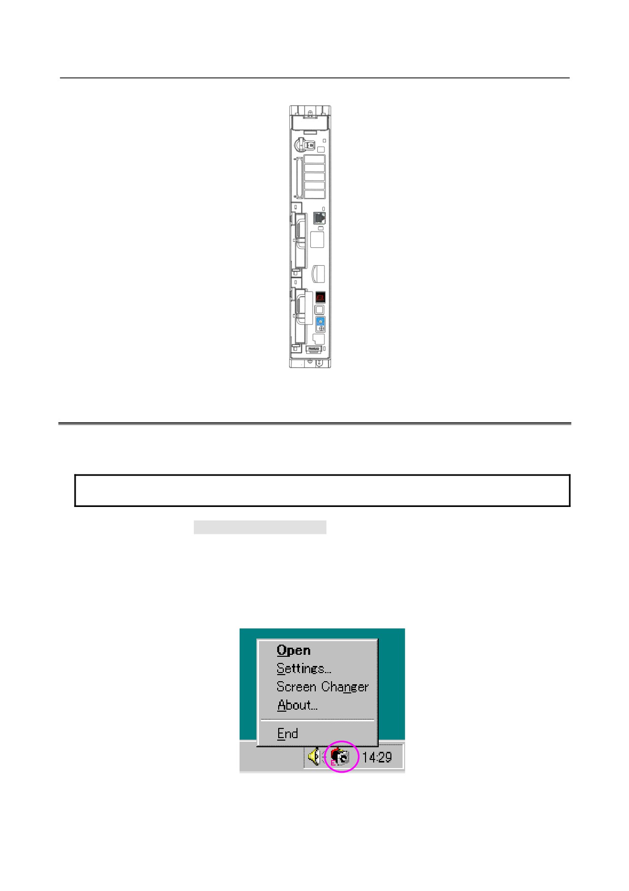
Tip: Hardware locations related to Ethernet Display function
CNM1B: Memory card slot
CD38A: Embedded Ethernet
(embedded port)
COP21A: LCD connector
STATUS: 7-segment LED
MTSW: Rotary switch
PSW: Push switch
Fig. H.5 (a) Hardware locations related to the Ethernet display function
H.6 NCBOOT32E.exe
NCBOOT32E.exe is software that monitors communication between the personal computer and CNCs
and displays a maintenance screen as needed.
NOTE
NCBOOT32E.exe is held on the Disk for CNC Screen Display function.
Set the rotary switch to "F" (Function number F) then start the CNC. The boot screen and the IPL
screen are displayed in this order.
With NCBOOT32E.exe, application software to be started after the IPL screen is displayed can also be
registered. Usually, CNC Screen Display function (CNCScrnE.exe) is registered.
NCBOOT32E.exe resides on the system tray after the start-up.
By right-clicking the icon (circled on the screen below) on the system tray, the pop-up menu shown Fig.
H.6 (a) is displayed.
Fig. H.6 (a)
When [Open] is selected, the status screen is displayed.
When [Settings...] is selected, the option setting screen is displayed.
When [Screen Changer] is selected, the changer screen is displayed.
- 794 -
B-64485EN/01
APPENDIX H.ETHERNET DISPLAY FUNCTION
When [About...] is selected, the version information dialog box is displayed.
When [End] is selected, NCBOOT32E.exe ends.
Double-clicking the icon on the system tray displays the status screen.
By left-clicking the icon on the system tray, the pop-up menu shown Fig. H.6 (b) is displayed. Those
CNCs that are not currently connected are dimmed.
Fig. H.6 (b)
When a node number is selected from the pop-up menu, the current screen (boot screen, IPL screen, CNC
alarm screen, or screen of an automatically started application) of the currently connected CNC can be
displayed in the forefront.
NOTE
To operate NCBOOT32E.exe, the use of a mouse or a touch panel is
recommended.
H.6.1 Boot Screen
If the rotary switch on a CNC is set to "F" (Function number F), the boot screen is displayed when
communication between NCBOOT32E.exe and the CNC is established.
When multiple CNCs are connected, multiple boot screens are displayed.
Fig. H.6.1 (a)
- 795 -
H.ETHERNET DISPLAY FUNCTION APPENDIX
B-64485EN/01
The following operations can be performed on the boot screen:
• Selection of a location to which an F-ROM/S-RAM file is to be saved (the memory card of the CNC
or a folder on the hard disk of the personal computer)
• Writing files of user data (such as macro programs and ladder programs) to the F-ROM of the CNC
• Saving user data held on the F-ROM to a file
• Checking system data or user data held on the F-ROM
• Deleting user data from the F-ROM
• Backing up the data held on the S-RAM of the CNC to a file
• Restoring the S-RAM data backed up to a file to the CNC
• Restoring the S-RAM data automatically backed up to the F-ROM
• Formatting the memory card of the CNC
H.6.2 File Storage Location Selection
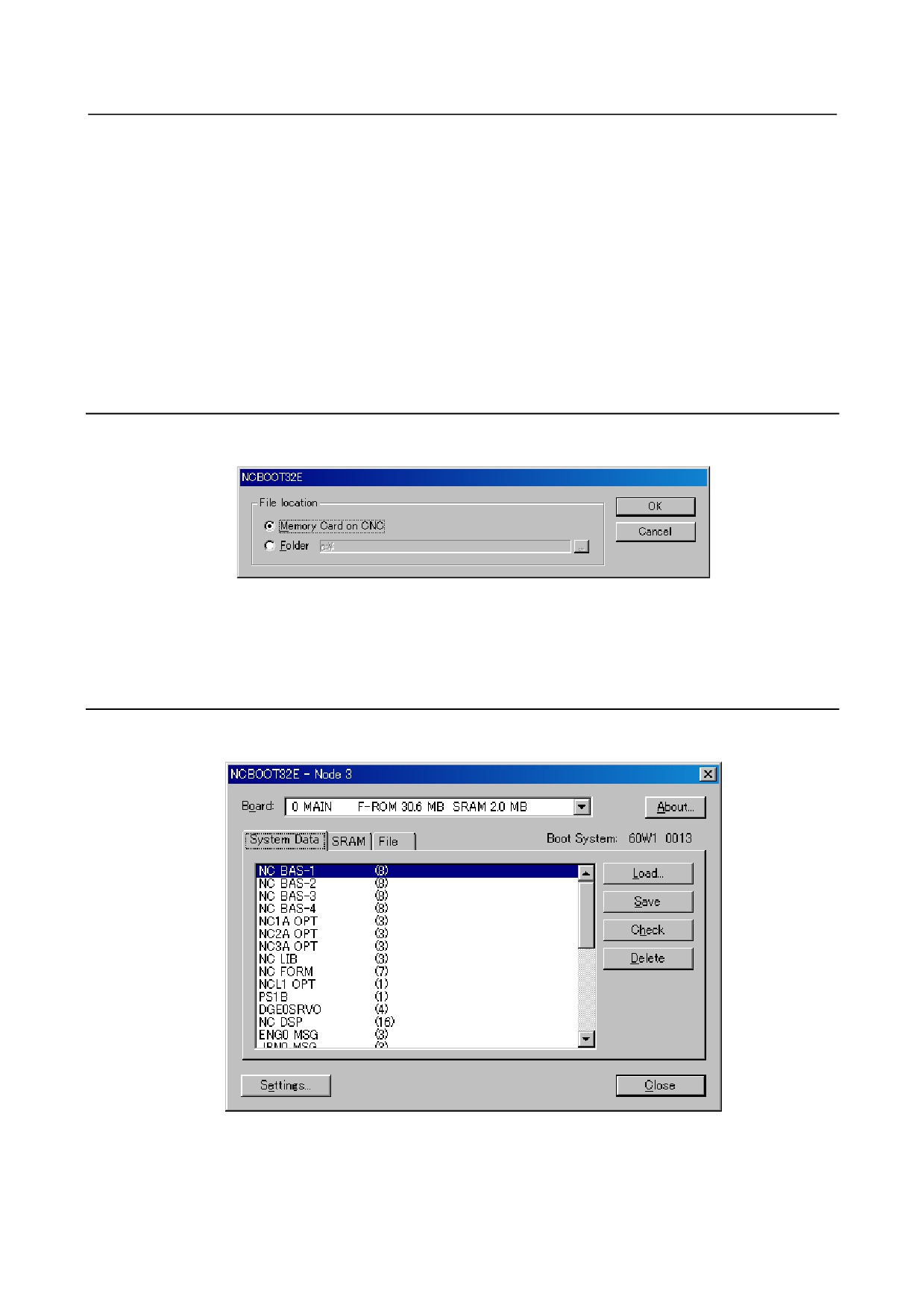
Clicking the [Settings...] button displays the screen shown Fig. H.6.2 (a).
Specify a location for storing an user data file or S-RAM data file.
Fig. H.6.2 (a)
Select the memory card of the CNC or a folder on the hard disk of the personal computer.
The selection can be changed at any time.
H.6.3 User Data Operation
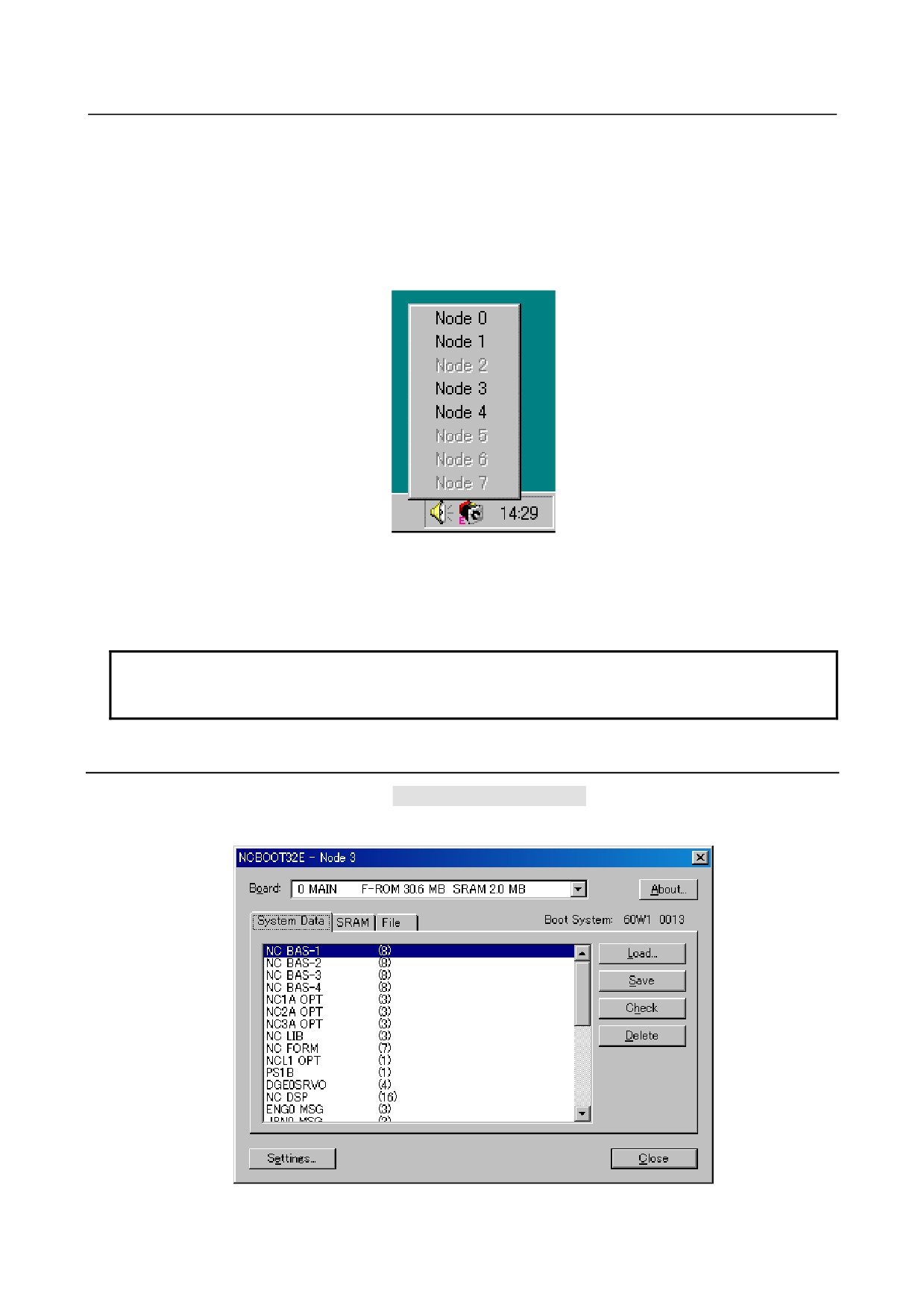
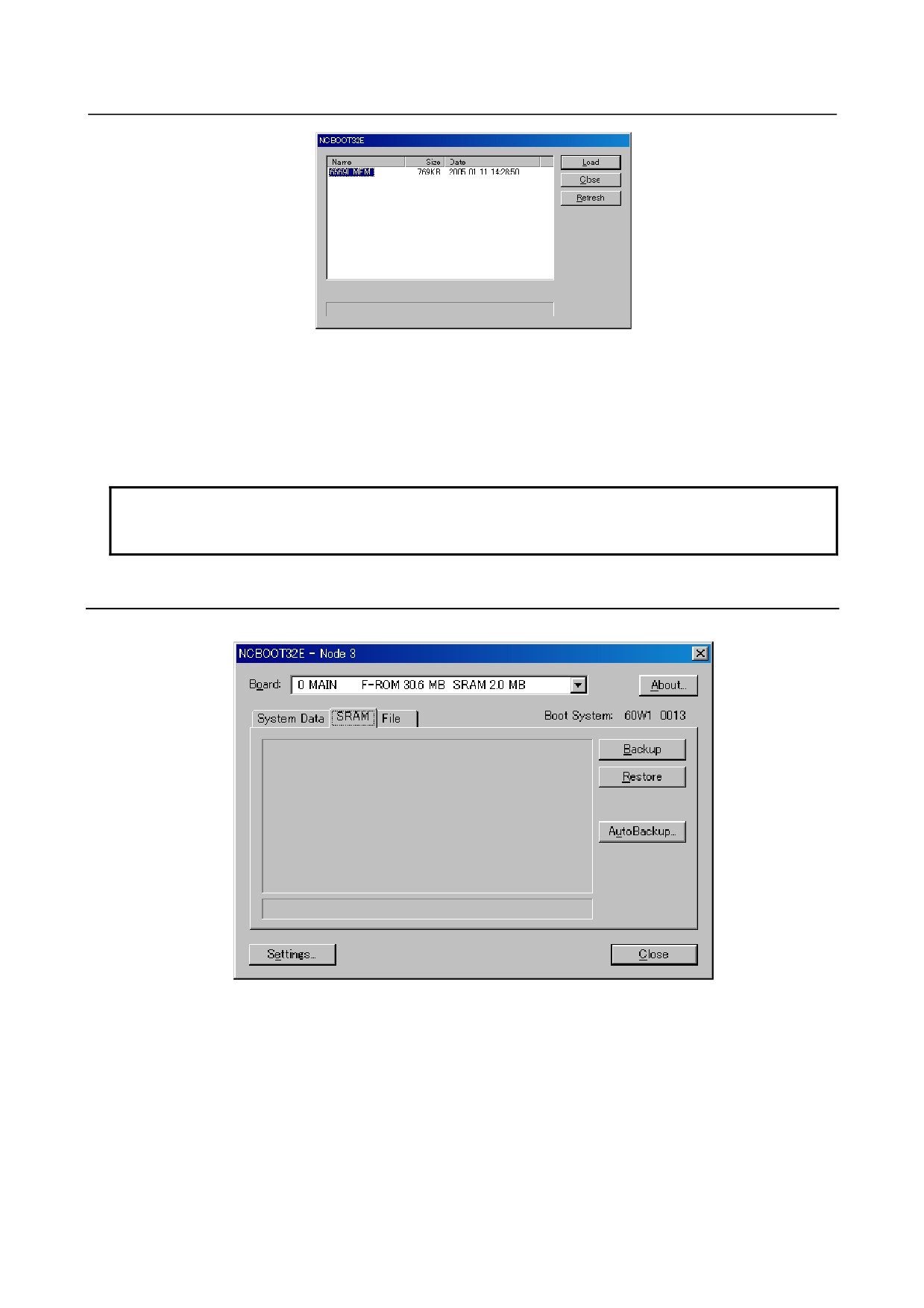
Clicking the [System Data] tab displays a screen as shown Fig. H.6.3 (a).
The screen is used to operate user data written in the F-ROM of the CNC.
Fig. H.6.3 (a)
Clicking the [Load...] button displays the file selection screen.
- 796 -
B-64485EN/01
APPENDIX H.ETHERNET DISPLAY FUNCTION
Fig. H.6.3 (b)
Select user data to be stored in the F-ROM of the CNC then click the [Load] button. The selected file or
files are written into the F-ROM of the CNC.
Clicking the [Save] button saves user data selected from the F-ROM of the CNC to a file.
Clicking the [Check] button checks selected system data or user data and displays check information.
Clicking the [Delete] button deletes selected user data from the F-ROM of the CNC.
NOTE
Only user data holding ladder programs and so forth can be operated as system
data with the [Load] button, [Save] button, and [Delete] button.
H.6.4 S-RAM Operation
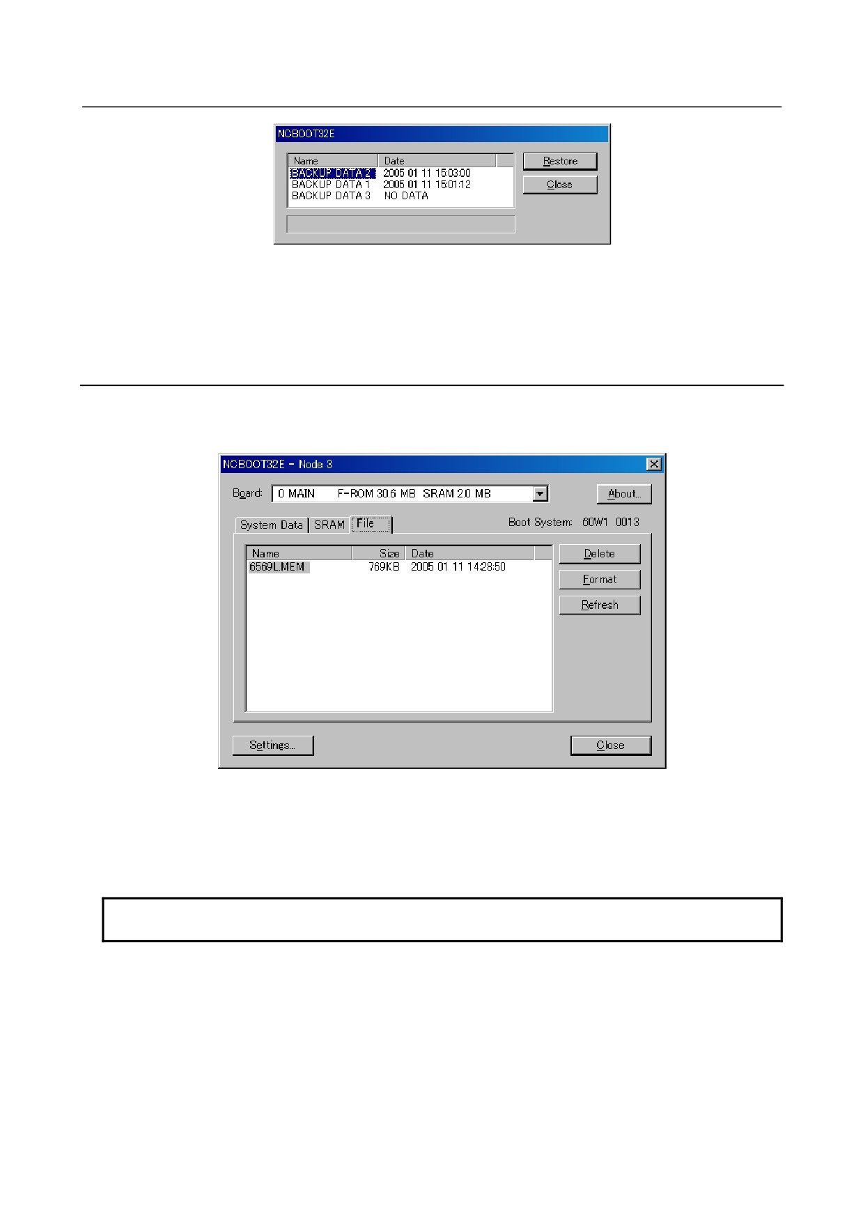
Clicking the [SRAM] tab displays a screen as shown Fig. H.6.4 (a).
Fig. H.6.4 (a)
This screen is used to operate data stored in the S-RAM of the CNC.
Clicking the [Backup] button backs up S-RAM data to a file.
Clicking the [Restore] button restores S-RAM data backed up to a file to the CNC.
Clicking the [AutoBackup...] button displays the file selection screen.
- 797 -
H.ETHERNET DISPLAY FUNCTION APPENDIX
B-64485EN/01
Fig. H.6.4 (b)
The screen displays S-RAM data automatically backed up by the CNC to the F-ROM.
To restore data, select the data then click the [Restore] button. The name of a backup file is automatically
determined and cannot be modified.
H.6.5 File Operation
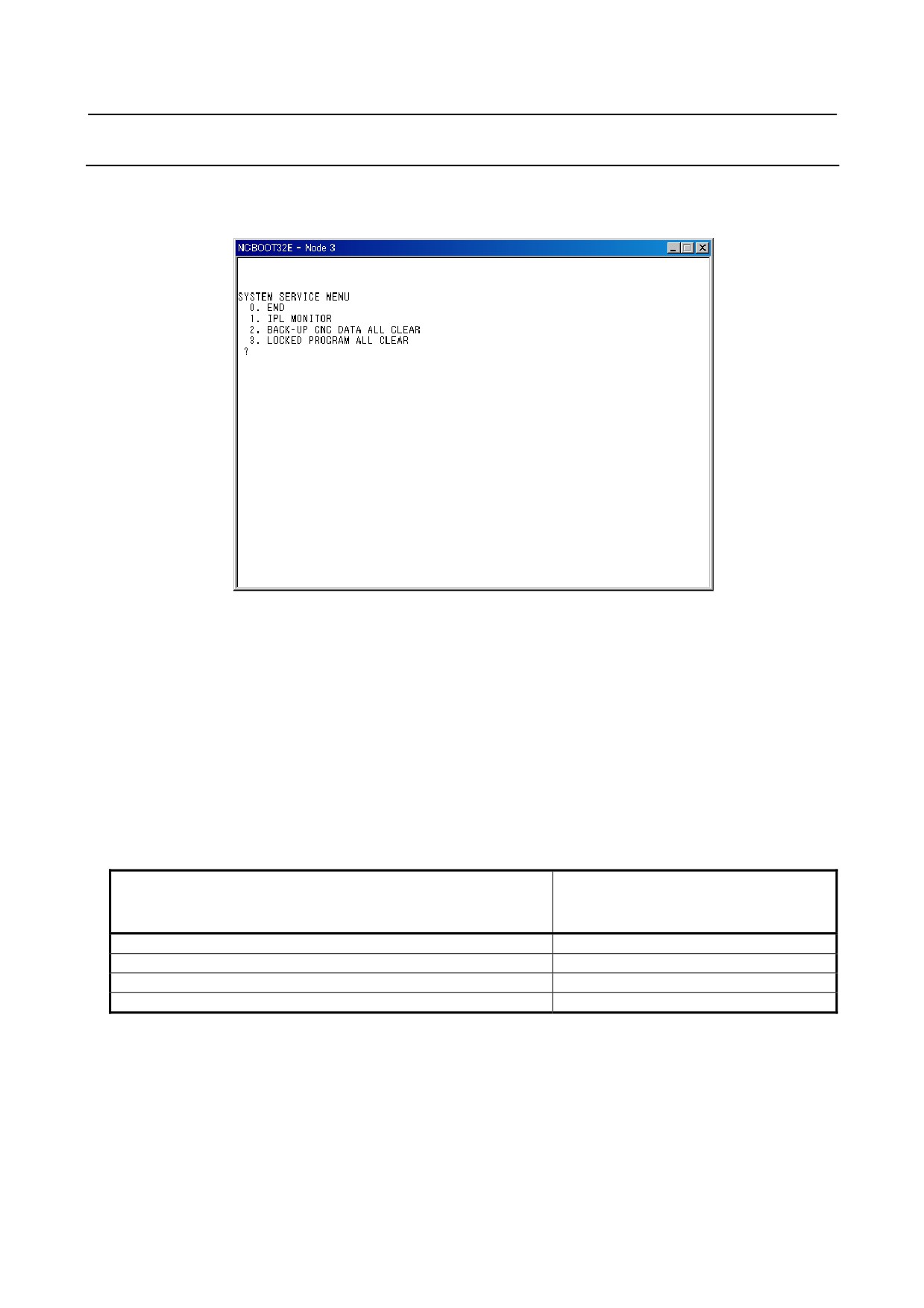
Clicking the [File] tab displays a screen as shown Fig. H.6.5 (a).
This screen is used to operate files on the memory card of the CNC or on the hard disk of the personal
computer.
Fig. H.6.5 (a)
Clicking the [Delete] button deletes a selected file.
Clicking the [Format] button formats the memory card of the CNC. This button is enabled only when the
memory card is selected with [Settings...].
Clicking the [Refresh] button updates the list of files. Click this button when the memory card is replaced.
NOTE
When the memory card is formatted, all data on the memory card is erased.
- 798 -
B-64485EN/01
APPENDIX H.ETHERNET DISPLAY FUNCTION
H.6.6 IPL Screen
By clicking the [Close] button on the boot screen, the boot screen disappears and the IPL screen is
displayed.
When multiple CNCs are connected, multiple IPL screens are displayed.
Fig. H.6.6 (a)
On the IPL screen, the following functions can be selected:
• Starting of the IPL monitor
• Clearing of data stored in the S-RAM of the CNC
• Clearing of CNC parameters
Supplement)
If a CNC-dedicated display unit is connected, a function of SYSTEM SERVICE MENU of the IPL
screen can be operated according to the corresponding MDI key operation performed at CNC
power-on time. If Ethernet Display function is used, however, such MDI key operation is disabled.
In this case, select a desired function from SYSTEM SERVICE MENU on the IPL screen.
Table H.6.6 (a)
(Tip)
SYSTEM SERVICE MENU items corresponding to the operations
MDI key operations on CNC-dedicated
listed in right-hand column
display unit at power-on time
0. END
None
1. IPL MONITOR
<-> + <.>
2. BACK-UP CNC DATA ALL CLEAR
<DELETE> + <RESET>
3. LOCKED PROGRAM ALL CLEAR
<M> + <O>
- 799 -
H.ETHERNET DISPLAY FUNCTION APPENDIX
B-64485EN/01
H.6.7 CNC Alarm Screen
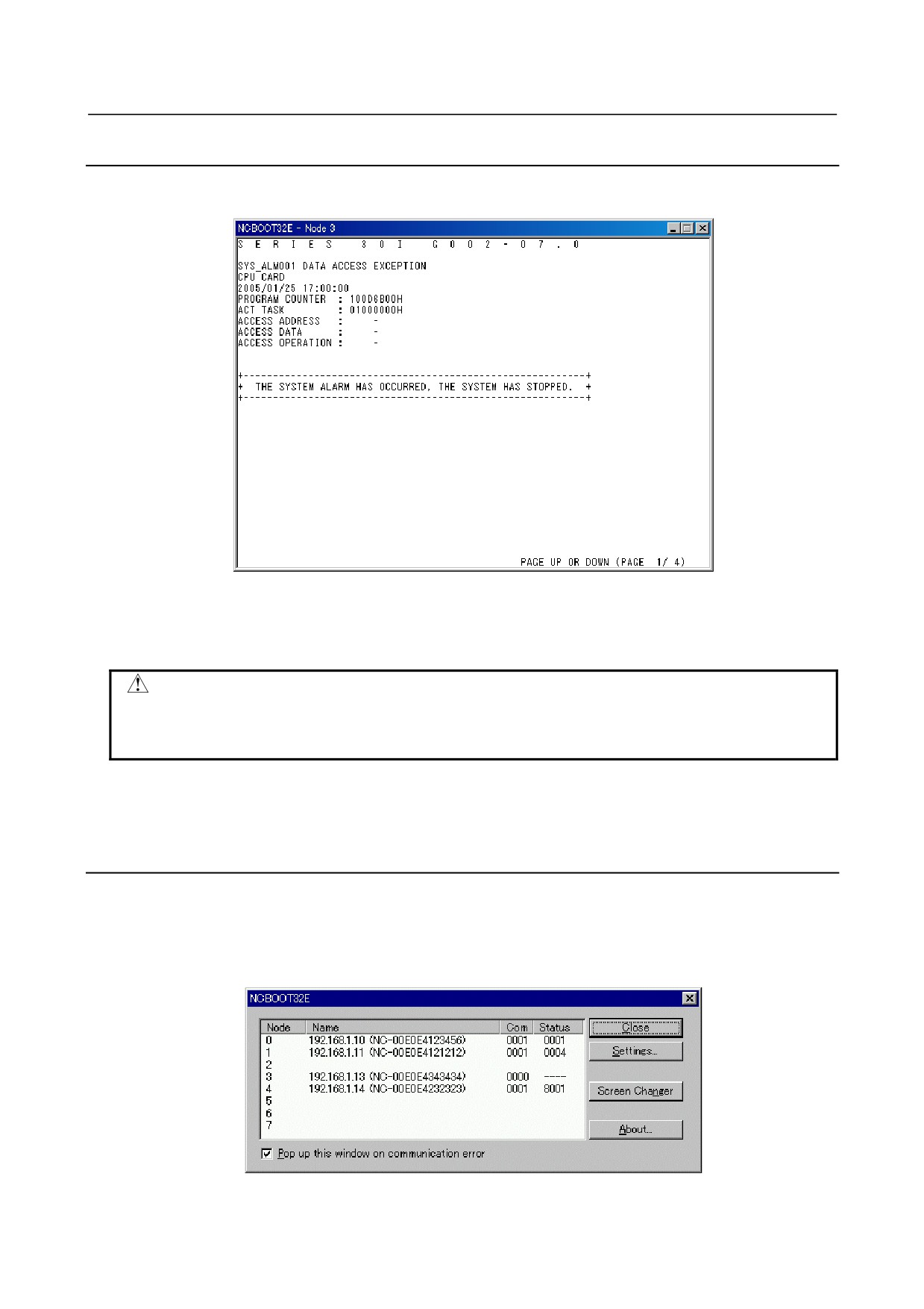
The CNC alarm screen is displayed when a system alarm occurs from a CNC.
If a system alarm occurs from multiple CNCs, multiple CNC alarm screens are displayed.
Fig. H.6.7 (a)
(The screen above is just an example. Display information varies according to a system alarm issued from
a CNC.)
CAUTION
If a system alarm occurs due to a very serious fault related to the memory, main
CPU, or Embedded Ethernet, the CNC system alarm screen might not be
displayed.
For details of CNC alarm screen operation and display, see Section 11.25, "SYSTEM ALARMS", and
Section 11.26, "SYSTEM ALARMS RELATED TO THE PMC AND I/O LINK".
H.6.8 Status Screen
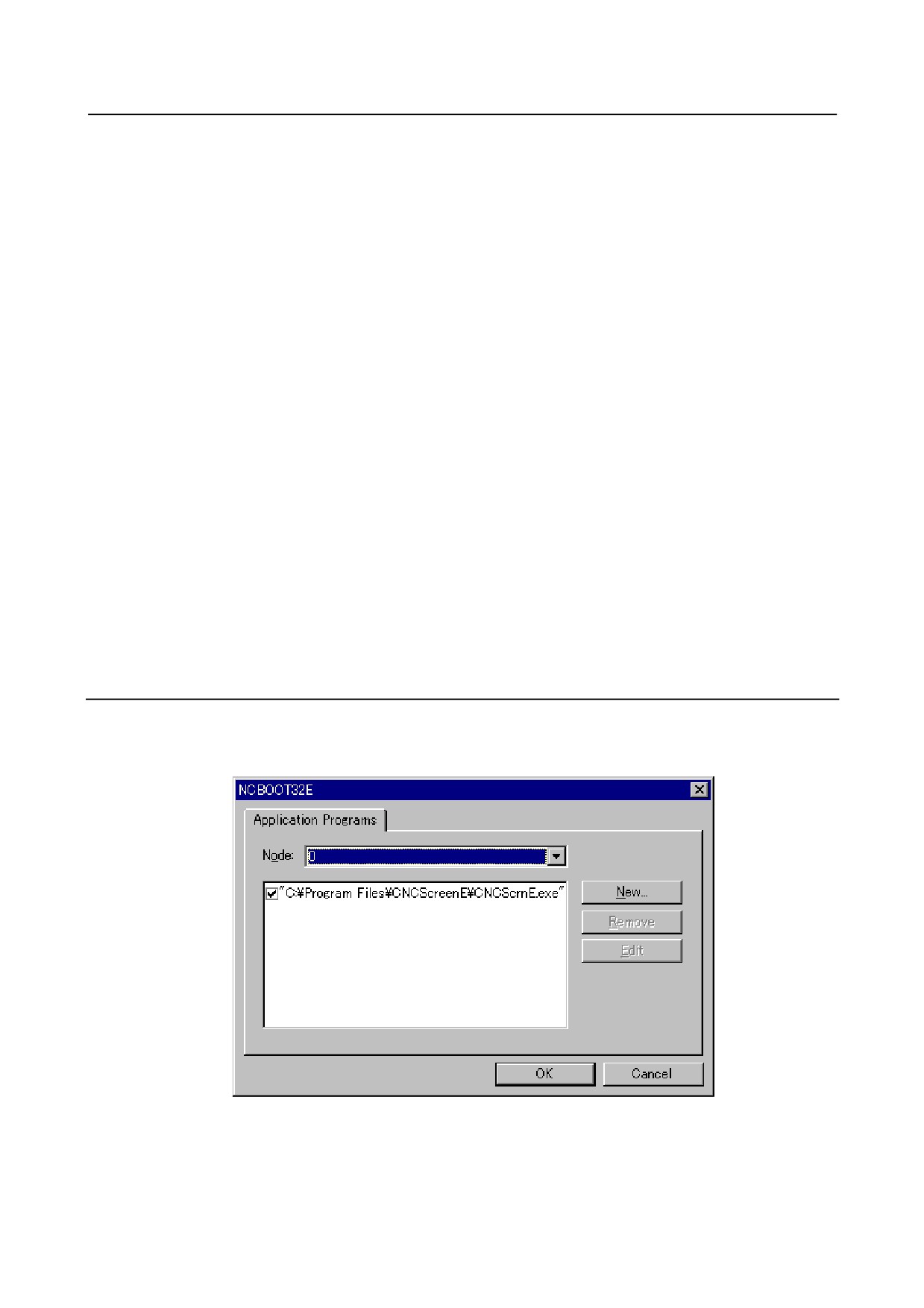
When any of the following operations is performed, a screen as shown Fig. H.6.8 (a) is displayed:
• Double-click the icon on the system tray
• Right-click the icon on the system tray then click [Open] on the pop-up menu
By checking [Pop up this window on communication error] beforehand, the screen is displayed
immediately when a communication error occurs.
Fig. H.6.8 (a)
- 800 -
B-64485EN/01
APPENDIX H.ETHERNET DISPLAY FUNCTION
On the status screen, the IP address and MAC address, current communication status, and other statuses
of each CNC currently connected can be checked.
Node
: CNC node number (0 to 7)
When a duplicate IP address or MAC address is specified for a CNC, the node number is
followed by "X". In this case, normal communication is disabled.
Name
: Name of a CNC based on the IP address and MAC address
Blank
: Not connected
----
: Duplicate IP address or MAC address
Com
: Communication status
Blank
: Disconnected
0000
: Status that the communication was established once but it is being disconnected now
0001
: Connecting
8000
: Communication error in progress
----
: Duplicate IP address or MAC address
Status
: CNC status
Blank
: Disconnected
0001
: Boot processing in progress
0002
: Boot processing completed
0003
: IPL processing in progress
0004
: IPL processing completed
0010
: Steady state
0011
: The node number is not 0 though CNC does not have the option of Ethernet Display
function
8???
: System alarm issued
----
: Communication stopped, communication error, duplicate IP address or MAC address
H.6.9 Option Setting Screen
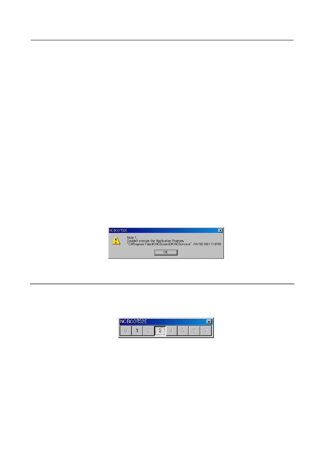
When any of the operation is performed, a screen as shown Fig. H.6.9 (a) is displayed:
• Right-click the icon on the system tray then click [Settings…] on the pop-up menu
• Click [Settings…] on the status screen
Fig. H.6.9 (a)
On the option setting screen, application software for display to be started after IPL processing can be
registered.
In addition, turning on the check box causes the application software of interest to run in association with
the changer screen, thus enabling the following operations.
- 801 -
H.ETHERNET DISPLAY FUNCTION APPENDIX
B-64485EN/01
(For details, see H.6.10, “Changer Screen”.)
• When a node number is selected on the changer screen, the checked application software is
displayed at the forefront and thus becomes operable.
• When the checked application software is exited, a prompt is displayed to ask whether to restart it.
If you want to keep any application software running, you are recommended to turn on the check
box for it.
When a node is selected from the [Node] list box, the name of the application software registered for the
node is displayed at the center of the screen.
Clicking the [New...] button can register an application name. If the path includes a blank character,
enclose the path in double quotation marks.
Clicking the [Remove] button deletes a selected application name.
Clicking the [Edit] button enables a selected application name to be edited. When an argument is
specified, the character string "%s" in the command line is replaced with an IP address. To represent "%"
itself, code "%%".
Example)
To operate CNC Screen Display function, code an application name as follows:
“C:\Program Files\CNCScreenE\CNCScrnE.exe” /H=%s:8193
For each node (CNC), multiple applications can be registered on the option setting screen. All registered
applications are started simultaneously.
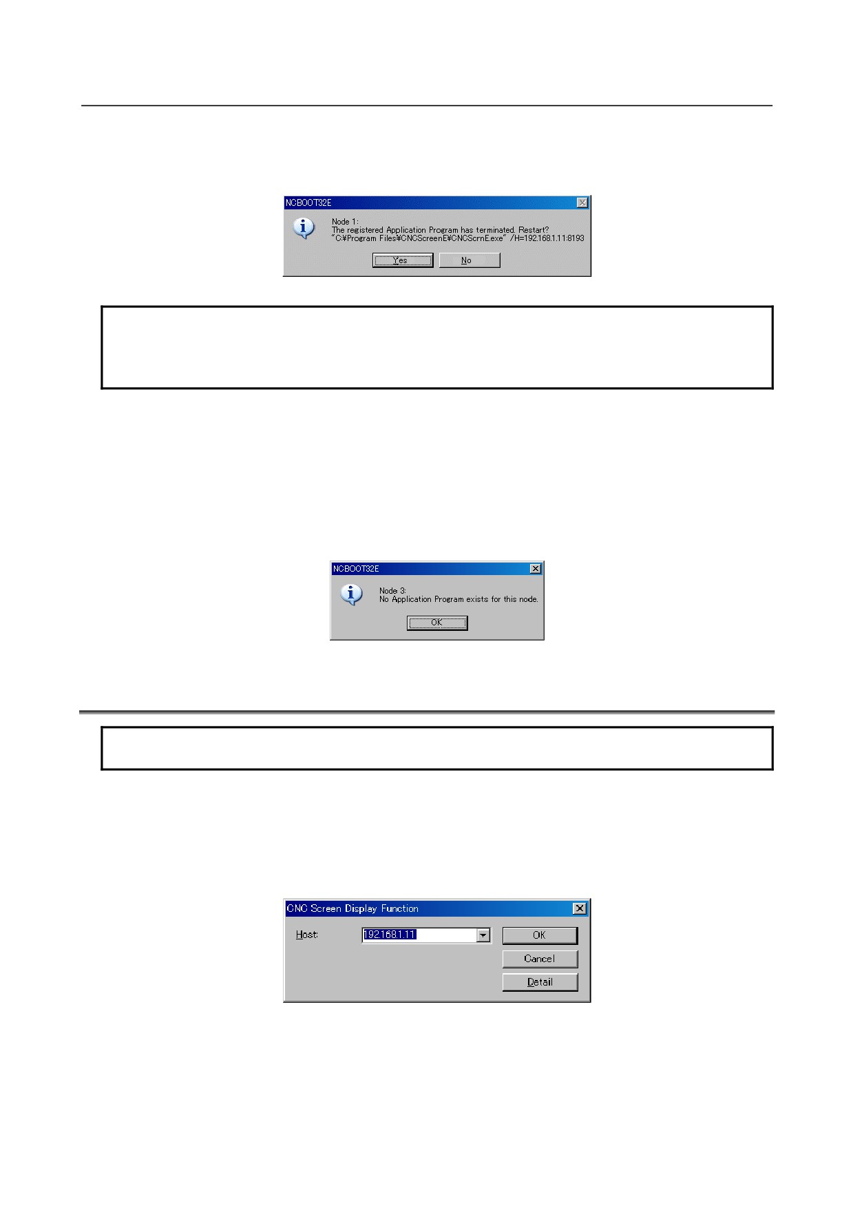
If a register application software cannot be started normally, the dialog box "Node [xxx]:Couldn't execute
the Application Program.[yyy]" is displayed. ([xxx] represents a node number, and [yyy] represents a
command line character string.)
Fig. H.6.9 (b)
H.6.10 Changer Screen
When any of the following operations is performed, a screen as shown Fig. H.6.10 (a) is displayed:
• Right-click the icon on the system tray then click [Screen Changer] on the pop-up menu
• Click [Screen Changer] on the status screen
• Press the hotkey (Ctrl-Alt-N)
Fig. H.6.10 (a)
The changer screen is displayed in the forefront with other screens hidden behind.
The changer screen is always laid on the other screens.
In addition, any application software registered with its check box turned on the option setting screen, the
BOOT screen, IPL screen, and the CNC alarm screen
(hereafter generically referred to as the
changer-target application) operate in association with the changer screen.
A depressed node number on the changer screen means that the corresponding changer-target application
is displayed at the forefront.
- 802 -
B-64485EN/01
APPENDIX H.ETHERNET DISPLAY FUNCTION
If the changer target application that should have been automatically started is terminated, the dialog box
"Node [xxx]:The registered Application Program has terminated. Restart? [yyy]" is displayed. Clicking
the [Yes] button starts the application again. ([xxx] represents a node number, and [yyy] represents a
command line character string.)
Fig. H.6.10 (b)
NOTE
When you click the [No] button, the changer target application is not started
again. Even if the changer target application is manually started later, interaction
with the changer screen is disabled.
Clicking a non-depressed node number causes the changer-target application corresponding to the
non-depressed node number to be displayed at the forefront.
Alternatively, pressing the Shift+Fx keys causes the changer-target application corresponding to the node
number related to Shift+Fx to be displayed at the forefront.
Shift+F1: Node0, Shift+F2: Node1, Shift+F3: Node2, Shift+F4: Node3、
Shift+F5: Node4, Shift+F6: Node5, Shift+F7: Node6, Shift+F8: Node7
If no changer-target application is found, the “Node [xxx]:No Application Program exists for this node.”
dialog box appears (where [xxx] is a node number).
Fig. H.6.10 (c)
H.7 STARTING OF THE CNC SCREEN DISPLAY FUNCTION
NOTE
To use CNC Screen Display function (A02B-0207-J858), its option is required.
To operate CNCScrnE.exe (CNC Screen Display function) after CNC initialization, the application name
of CNC Screen Display function needs to be registered on the option setting screen of NCBOOT32E.exe.
At this time, add an argument (/H=%s:8193) for specification of the IP address and port number of the
CNC to the application name.
If CNC Screen Display function is operated when no argument is added to the application name, the
screen shown Fig. H.7 (a) is displayed, and the IP address and port number must be set.
Fig. H.7 (a)
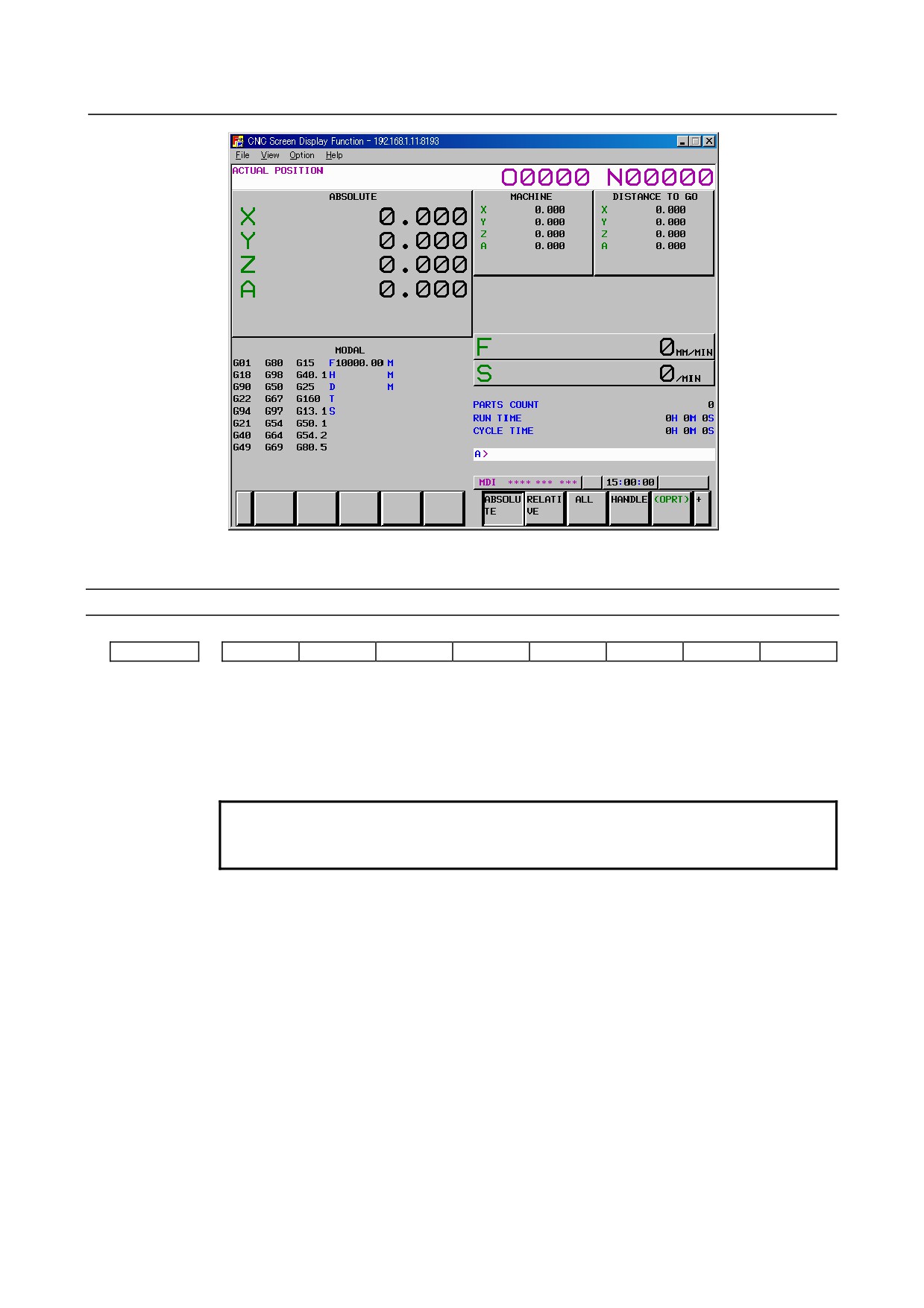
When a connection is made with a CNC, a CNC screen as shown Fig. H.7 (b) is displayed.
The title bar indicates the IP address and port number of the CNC.
- 803 -
H.ETHERNET DISPLAY FUNCTION APPENDIX
B-64485EN/01
Fig. H.7 (b)
Related NC parameters
#7
#6
#5
#4
#3
#2
#1
#0
13114
P15
[Data type] Bit
#0 P15 When the screen is displayed using the CNC screen display function:
0: The 10.4” mode is used.
1: The 15” mode is used.
NOTE
This parameter is effective when CNC Screen Display function is
used with the stand-alone type Series30i/31i/32i.
- 804 -
B-64485EN/01
APPENDIX
I.IPL MONITOR
I
IPL MONITOR
Appendix I, "IPL MONITOR", consists of the following sections:
I.1 OVERVIEW
805
I.2 STARTING OF THE IPL MONITOR
805
I.3 IPL MENU
806
I.1
OVERVIEW
With the IPL monitor, the following operations can be performed:
1)
Clearing of individual files
CNC parameters, tool compensation data, and so forth can be cleared.
2)
Output of system alarm information
System alarm information stored as history information can be output to the memory card.
WARNING
1 From the IPL monitor menu, do not select an item other than the items listed
below.
The other items represent functions for FANUC service.
0. END IPL
3. CLEAR FILE
5. SYSTEM ALARM UTILITY
2 When an individual file is cleared, all data stored in the file is cleared and
initialized. So, before clearing an individual file, back up the data of the file as
needed.
3 If a system label error has occurred, perform a clear operation according to
Appendix J, "MEMORY CLEAR OPERATION", instead of clearing of an
individual file.
I.2
STARTING OF THE IPL MONITOR
The IPL monitor can be started according to the procedure below.
Other than Personal Computer functions
<1> Turn on the power by pressing the MDI keys [.] and [-] simultaneously.
<2> The IPL monitor screen is displayed.
Personal Computer functions
<1> Start NCBOOT32.
<2> Select "1. IPL MONITOR" on the IPL screen.
<3> The IPL monitor screen is displayed.
For details, see Appendix F, "MAINTENANCE OF PERSONAL COMPUTER FUNCTIONS
(BOOT-UP AND IPL)".
- 805 -
I.IPL MONITOR
APPENDIX
B-64485EN/01
I.3
IPL MENU
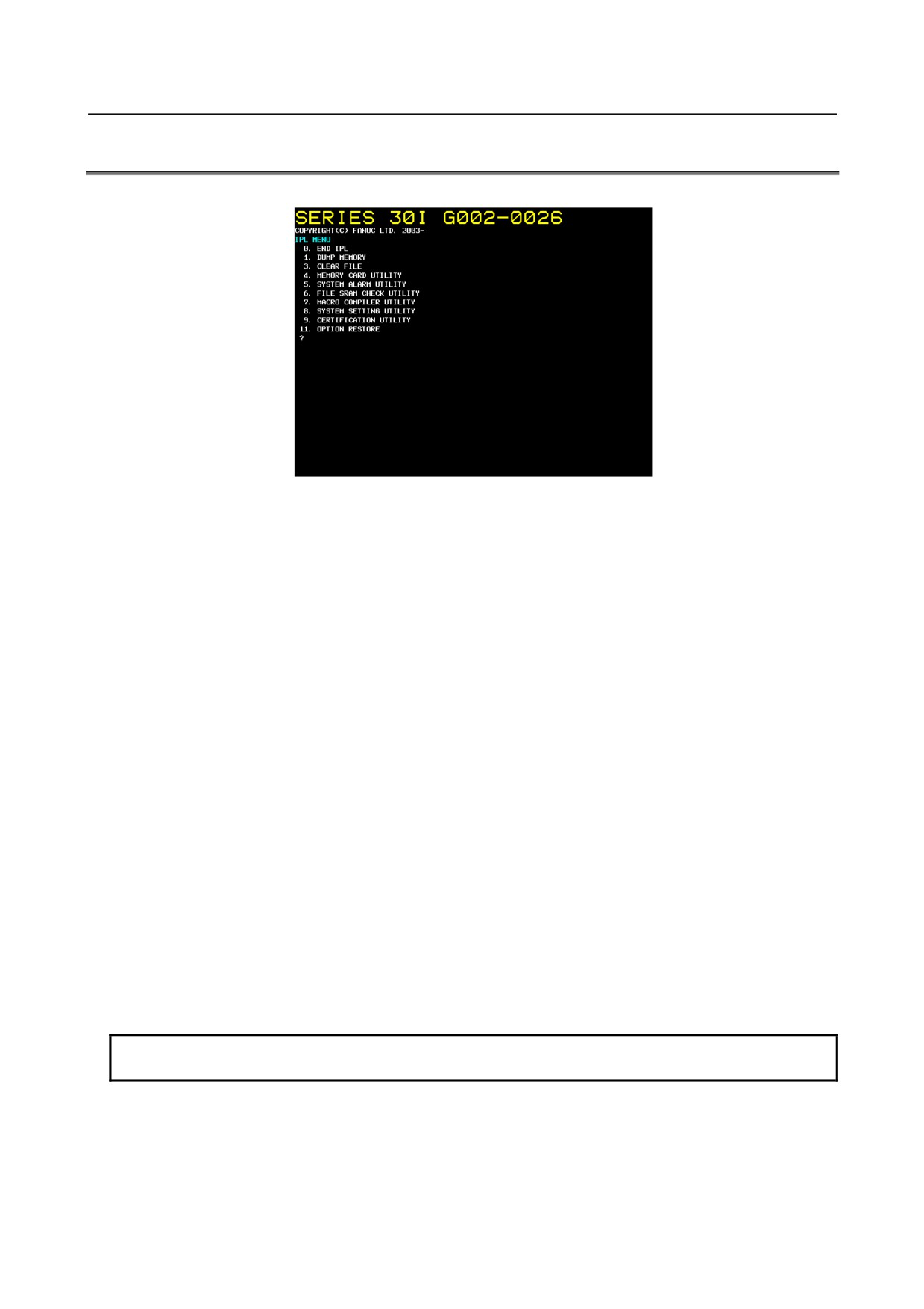
When the IPL monitor is started, the following screen (Fig. I.3 (a)) is displayed.
Fig. I.3 (a)
Enter a menu item number by using the corresponding MDI key.
One of the following menu items can be selected:
0 : END IPL
3 : CLEAR FILE
5 : SYSTEM ALARM UTILITY
END IPL
This menu item ends the IPL monitor and starts the CNC.
CLEAR FILE
This menu item clears and initializes displayed individual files.
1 : All files except option parameter files
2 : CNC parameter files
3 : Tool compensation data
Tool compensation memory A, B, and C, tool nose radius compensation data (including virtual tool
tip direction),
Y-axis offset data, second geometric offset, and so forth
4 : Program storage files
A default folder definition file is included.
5 : PMC parameter files
7 : Custom macro files
Macro variables, macro variable names
8 : Macro executor files
P code variables
9 : Touch panel data files
NOTE
The displayed individual file items vary, depending on the system configuration.
- 806 -
B-64485EN/01
APPENDIX
I.IPL MONITOR
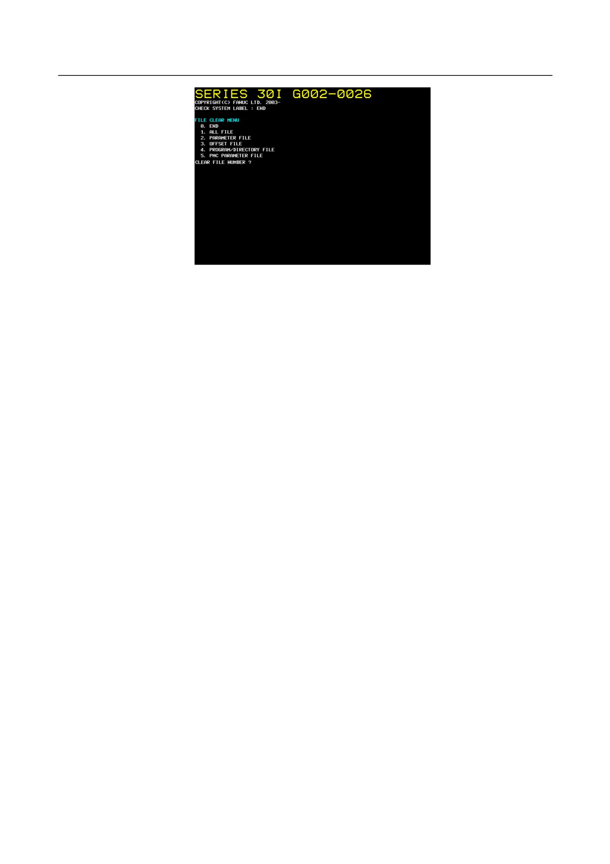
Fig. I.3 (b)
A file can be cleared according to the following procedure:
<1> Enter the number of a file to be cleared.
<2> The IPL monitor displays "CLEAR FILE OK ? (NO=0,YES=1)". Enter "1" to clear the file. To
cancel the clearing of the file, enter "0".
<3> When "1" is entered, the specified file is cleared then the menu above is displayed again.
<4> To clear an additional file, repeat steps <1> through <3>.
To quit, enter "0".
SYSTEM ALARM UTILITY
System alarm information can be output to the memory card.
For details, see Section
11.25, "SYSTEM ALARMS" in Chapter
11, "TROUBLESHOOTING
PROCEDURE".
- 807 -
J.MEMORY CLEAR
APPENDIX
B-64485EN/01
J MEMORY CLEAR
Appendix J, "MEMORY CLEAR", consists of the following sections:
G.1 OVERVIEW
808
G.2 OPERATION METHOD
808
G.3 DATA TYPES TO BE CLEARED
809
J.1
OVERVIEW
If an unexpected error occurs, such as the "SYSTEM LABEL CHECK ERROR" at system startup or the
"SYSTEM ALARM", which may be generated suddenly, this function can start up the CNC system in its
initial state to return the system to the state in which restoration work can be performed, by clearing all
data stored in CNC memory.
J.2
OPERATION METHOD
1.
Starting method
<1> For FS30i-B
When turning the power ON to the CNC, turn the power ON while pressing the MID keys
and
at the same time and holding them down. Keep holding them down until the memory all
clear approval screen is displayed.
<2> For Personal Computer functions with Windows® CE or Personal Computer functions with
Windows® XP
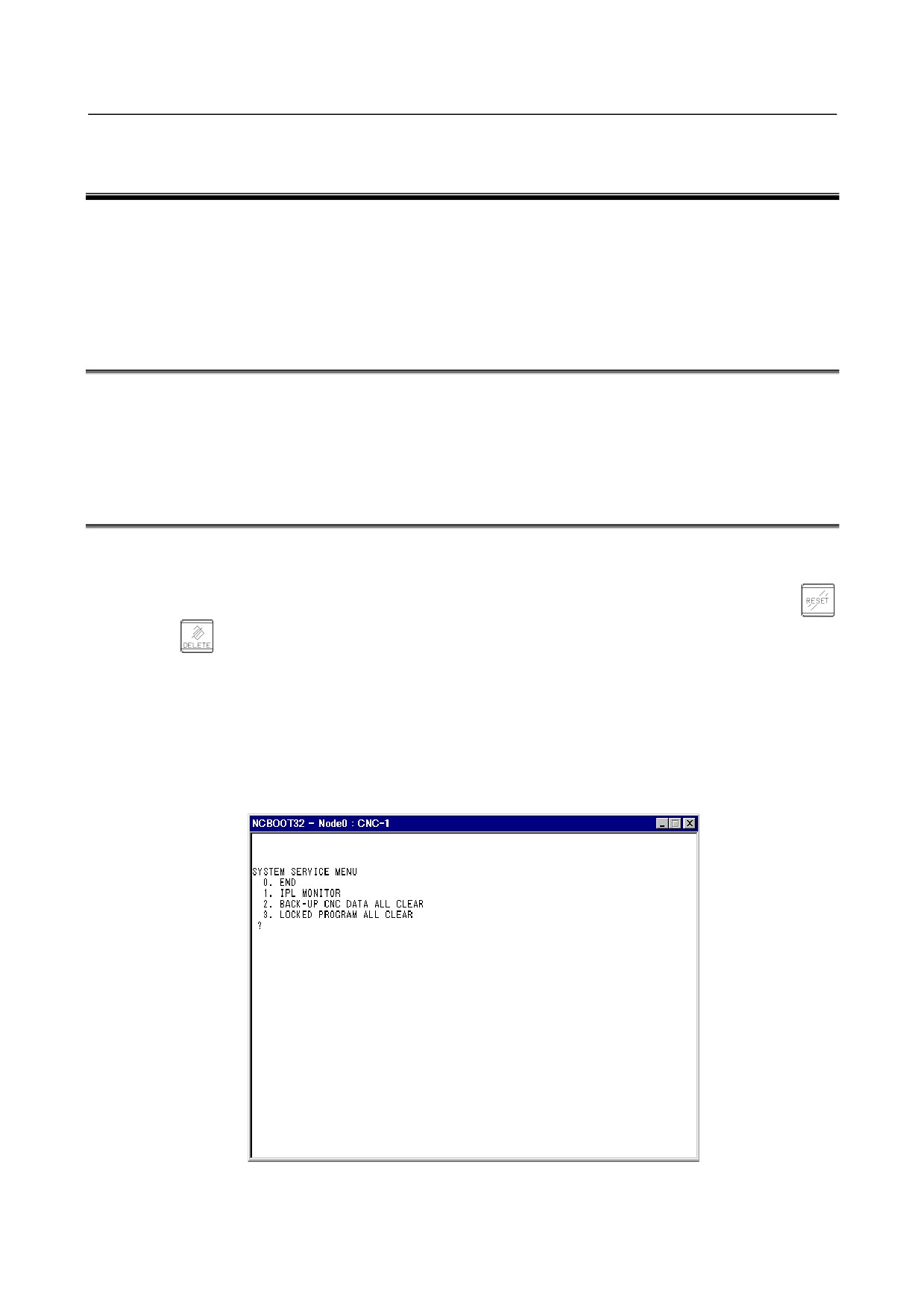
Use the NC BOOT32 function to display the IPL menu.
From the IPL menu, select "2. BACK-UP CNC DATA ALL CLEAR".
For details, see the chapter on "MAINTENANCE OPERATIONS
(BOOT AND IPL) FOR
PERSONAL COMPUTER FUNCTIONS".
Fig. J.2 (a)
2.
Memory all clear approval screen
- 808 -
B-64485EN/01
APPENDIX
J.MEMORY CLEAR
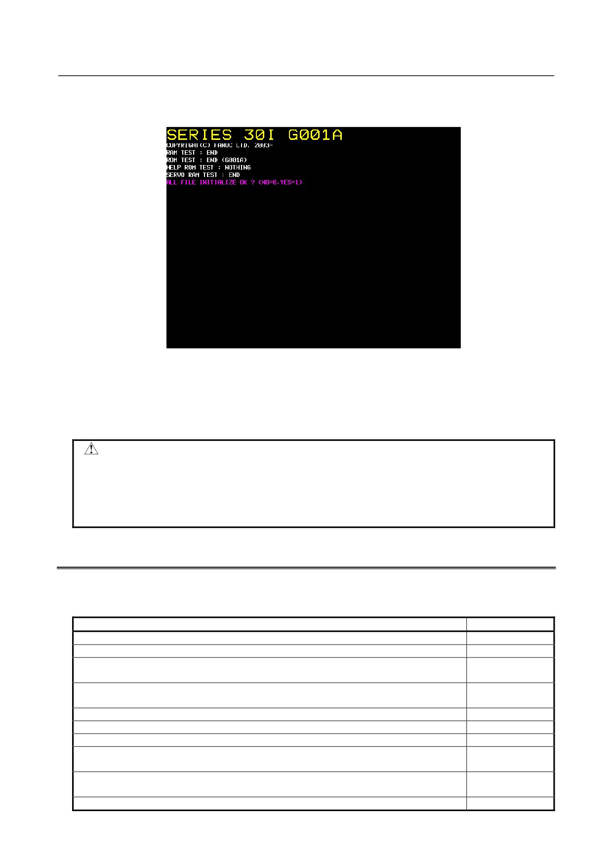
Performing the operation in 1. causes the following screen to be displayed, asking you whether to
execute all clear.
Fig. J.2 (b) Memory All Clear Approval Screen
From the screen shown above, select between the following operation and execute it:
-
If you do not want to execute memory all clear, press the numeric key "0". All clear will be
canceled.
-
To execute memory all clear, press the numeric key "1". All clear will be executed.
WARNING
1 When this operation is performed, the CNC system enters a state (initial state) in
which it can start up by itself. To restore various function operations, therefore,
you must reconfigure cleared data.
2 This operation can be performed only by personnel who have been trained in
maintenance and safety.
J.3
DATA TYPES TO BE CLEARED
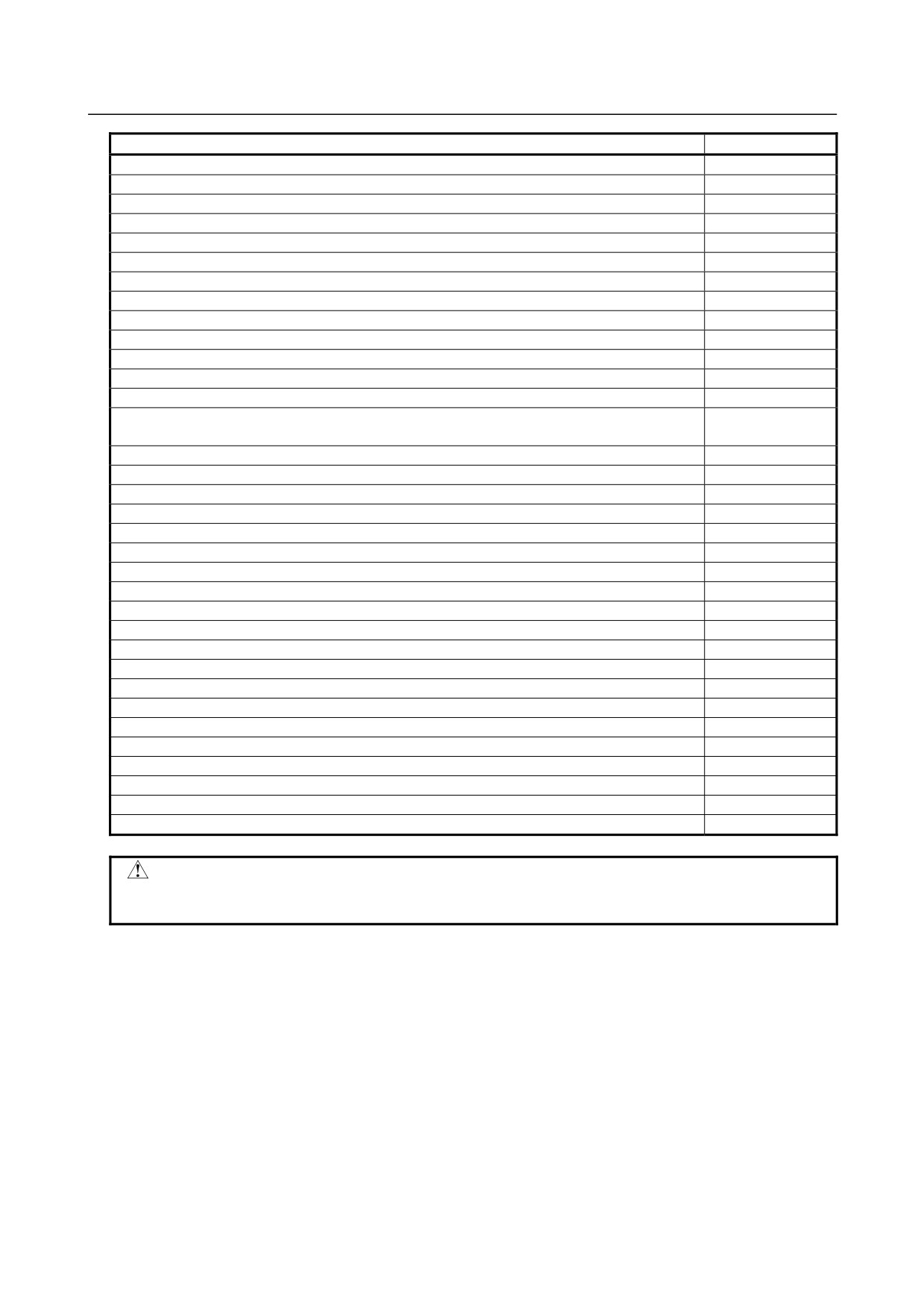
The various data types to be cleared by this operation are as follows:
Table J.3 (a)
Data type
Data area
System label
SRAM
Option parameters
SRAM
Data related to C Language Executor
SRAM
(such as SRAM disk data)
Data related to macro executor
SRAM
(such as P code variables, extended P code variables, user file data)
NC parameters
SRAM
Pitch error compensation data
SRAM
Custom macro variables, variable name
SRAM
Data related to PMC
SRAM
(such as parameters, KEEP relay value)
Data related to part program
SRAM/
(such as program main body, folder data)
FROM
Tool offset data
SRAM
- 809 -
J.MEMORY CLEAR
APPENDIX
B-64485EN/01
Data type
Data area
Default folder data
SRAM
Workpiece coordinate system addition data
SRAM
Tool life management data
SRAM
Rotary table dynamic fixture offset data
SRAM
System alarm history data
SRAM
Software operator’s panel data
SRAM
Three-dimensional error compensation data
SRAM
Periodic maintenance data
SRAM
Extended keep memory data
SRAM
Interpolation type straightness compensation data
SRAM
M code group data
SRAM
Data related to Fast Data Server / Fast Ethernet (such as parameters)
SRAM
Operation history data
SRAM
Bi-directional pitch error compensation data
SRAM
Extended bi-directional pitch error compensation data
Touch panel data
SRAM
Profibus master/slave function data
SRAM
Data related to customer’s board (such as parameters)
SRAM
DeviceNet master function data
SRAM
FL-net function data
SRAM
Rigid tapping retraction data
SRAM
Y-axis offset data
SRAM
Tool nose radius compensation value data
SRAM
Cutter compensation value data
SRAM
Second tool geometry offset data
SRAM
Data of interference check for each path
SRAM
Workpiece shift value data
SRAM
Embedded Ethernet data
SRAM
Data of protection of Data at Eight Levels
SRAM
Various data of tool management function
SRAM
Real time custom macro data
SRAM
FSSB data
SRAM
MANUAL GUIDE i data
SRAM
Dual check safety data
SRAM
Data related to C language board function
SRAM
CAUTION
The types of data stored in SRAM/FROM differ depending on the system
configuration.
- 810 -
B-64485EN/01
APPENDIX
K.USB FUNCTION MAINTENANCE
K USB FUNCTION MAINTENANCE
Appendix K "USB FUNCTION MAINTENANCE", consists of the following sections:
K.1 USB FUNCTION MAINTENANCE SCREEN
811
K.2 USB FUNCTION LOG SCREEN
813
K.1 USB FUNCTION MAINTENANCE SCREEN
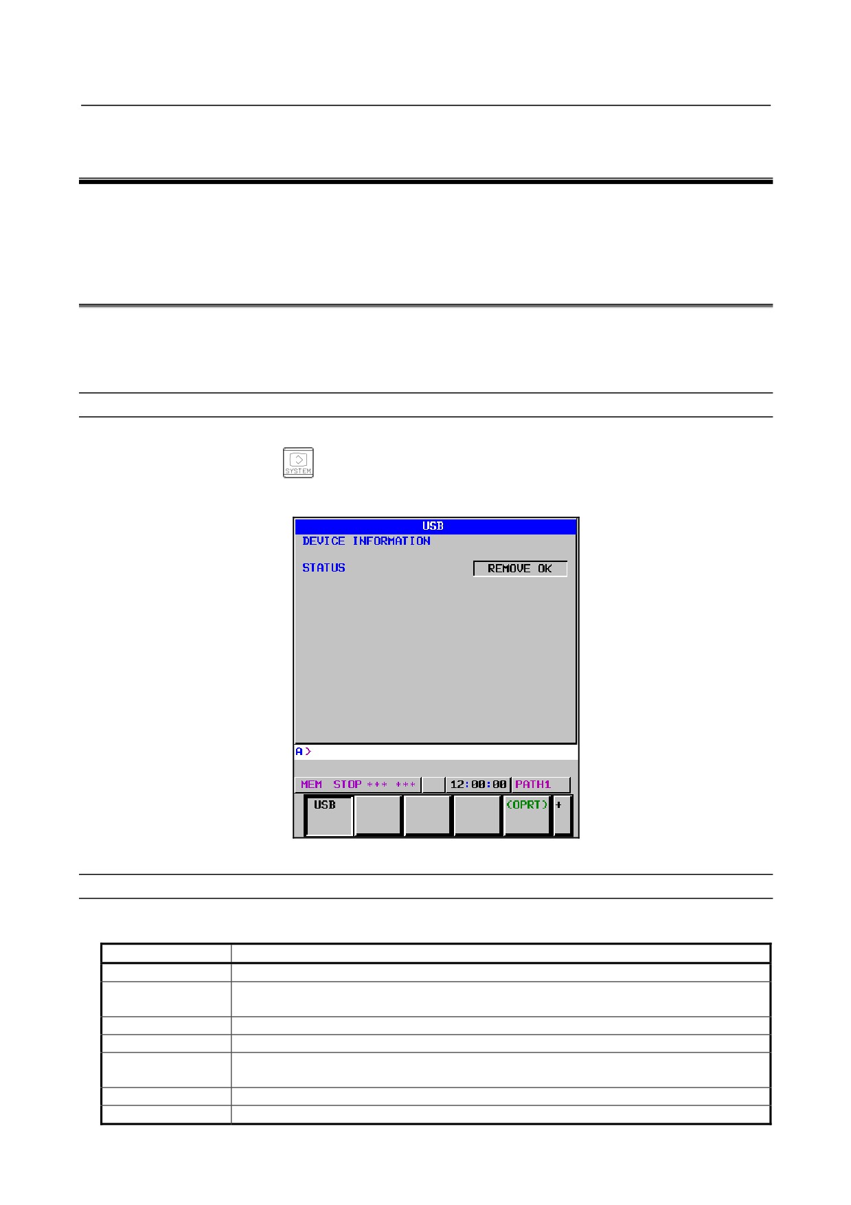
The USB function has maintenance screens.
On the maintenance screens, the USB memory status can be displayed and a USB memory can be
formatted.
Displaying the maintenance screen
Procedure
1
Press the function key
2
Press soft key [USB]. The USB screen appears. (If soft key [USB] is not displayed, press the
continuous menu key.)
Fig. K.1 (a) USB maintenance screen
Display items
Status
For [STATUS], the USB memory status is displayed as listed below.
State
Description
------
No USB memory is inserted.
REMOVE OK
A USB memory is inserted, but no data is input or output. The USB memory can be
removed and data can be input and output.
ACCESSING
The USB memory is being accessed and cannot be removed.
FORMATTING
The USB memory is being formatted and cannot be removed.
FORMAT OK
Formatting the USB memory terminated normally. The USB memory can be removed and
data can be input and output.
FORMAT NG
Formatting the USB memory terminated abnormally. Replace the USB memory.
ERROR
An unrecoverable error occurred. The USB function cannot be used.
- 811 -
K.USB FUNCTION MAINTENANCE APPENDIX
B-64485EN/01
CAUTION
While a USB memory is being formatted or is being accessed, do not turn the
power to the CNC off or remove the USB memory, or the USB memory may be
damaged.
NOTE
If [ERROR] is displayed for [STATUS], check the cause on the USB function log
screen, remove the cause, and turn the power to the CNC off, then on again.
Formatting the USB memory
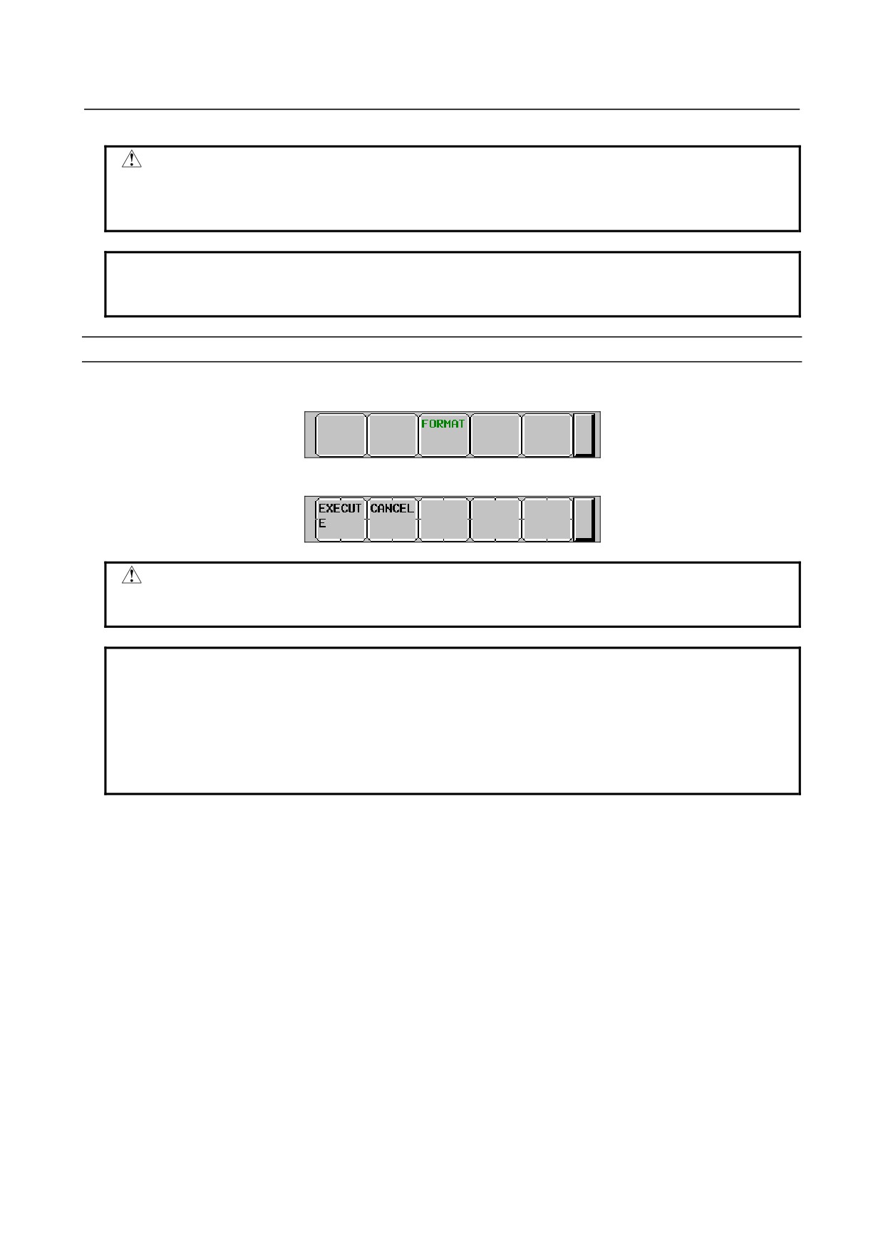
Procedure
1
Press soft key [(OPRT)]. Soft key [FORMAT] is displayed.
2
Press soft keys [FORMAT], then [EXECUTE]. Formatting starts.
CAUTION
While a USB memory is being formatted, do not turn the power to the CNC off or
remove the USB memory, or the USB memory may be damaged.
NOTE
1 Formatting may take time depending on the capacity of the USB memory and
manufacturer type. Formatting on the CNC once started cannot be canceled.
2 Formatting a USB memory deletes all files in the USB memory.
3 Any USB memory that is not physically formatted cannot be formatted on the
CNC. Format a USB memory to be used for the first time with FAT or FAT32
without specifying the Quick Format option on the personal computer.
- 812 -
B-64485EN/01
APPENDIX
K.USB FUNCTION MAINTENANCE
K.2 USB FUNCTION LOG SCREEN
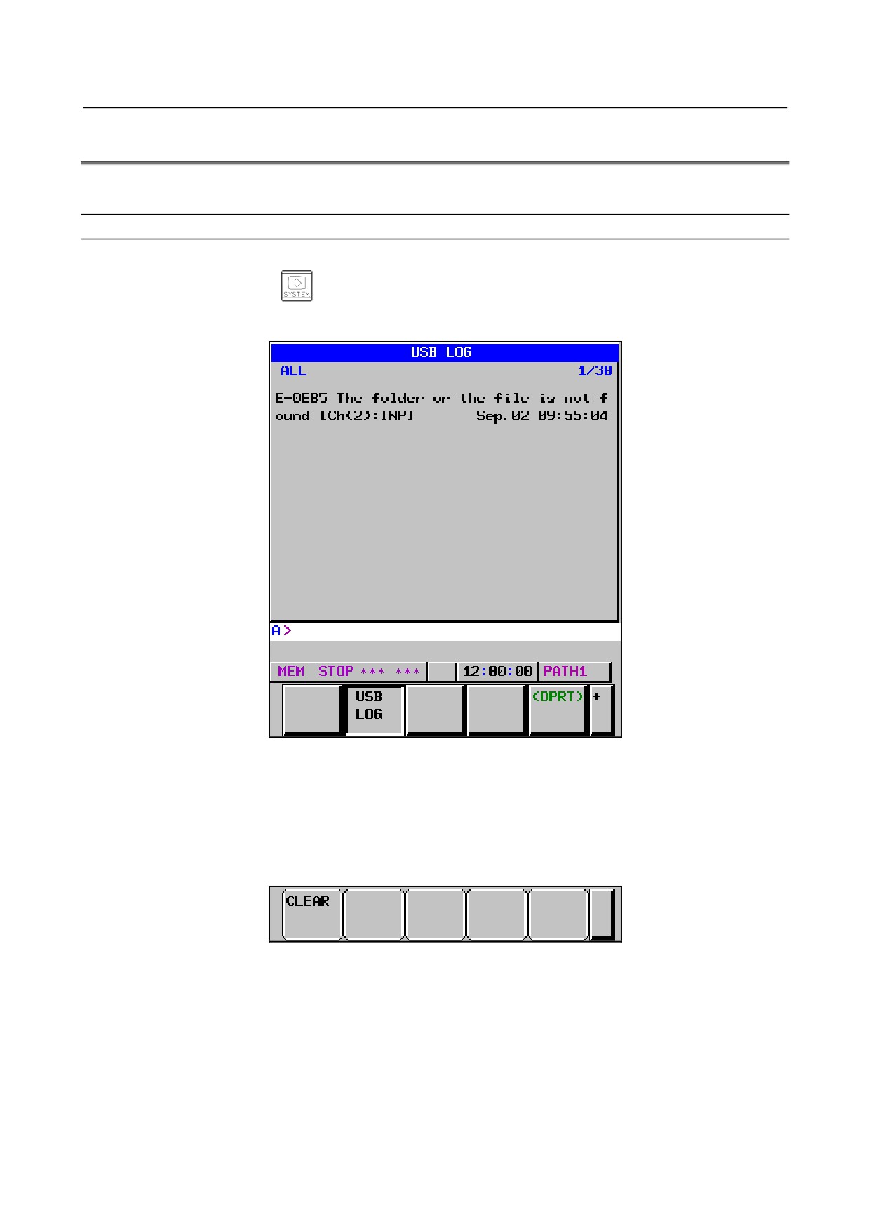
The USB function log screen displays the log related to the USB functions.
Displaying the USB function log screen
Procedure
1 Press the function key
2 Press soft key [USB LOG]. The USB LOG screen is displayed. (If soft key [USB LOG] is not
displayed, press the continuous menu key.)
Fig. K.2 (a) Log screen
The latest error log message is displayed at the top of the screen. At the end of the error log message, the
date and time when the error occurred are displayed. They are displayed in the following format:
“MMM.DD hh:mm:ss” (month (MMM), day (DD), hours (hh), minutes (mm), and seconds (ss)).
In the above example Fig. K.2(a), the date and time are 09:55:04 on September 2.
To clear the log, press soft keys [(OPRT)], then [CLEAR]. (Fig. K.2 (b))
Fig. K.2 (b)
- 813 -
K.USB FUNCTION MAINTENANCE APPENDIX
B-64485EN/01
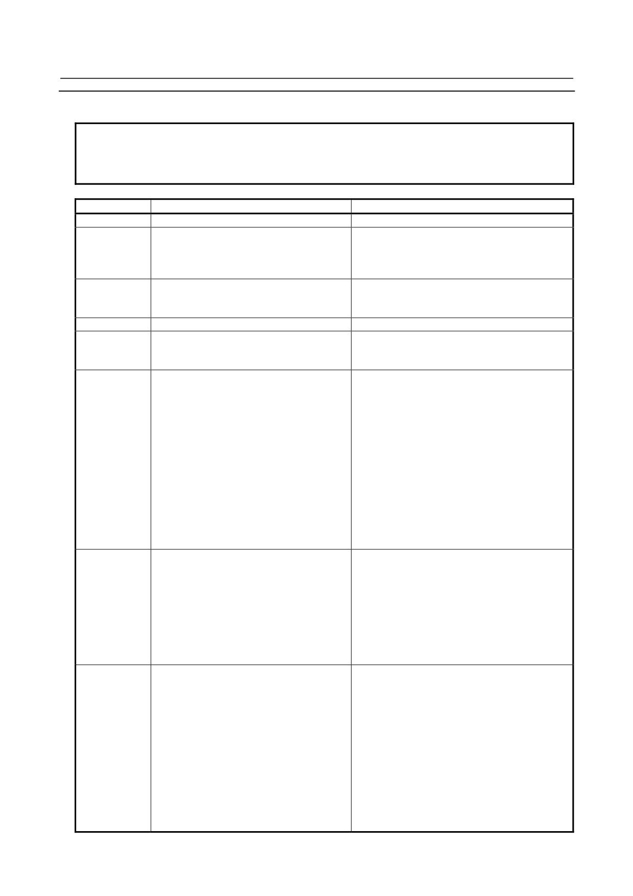
Errors and log messages
NOTE
For a log message, detail log message "[Ch(n):XXX]" may be output
simultaneously. If you still have trouble, contact FANUC with the relevant log
message and detail log message.
Error number
Log message
Meaning and corrective action
E-0E02
The number of the opening files is over
Up to 60 files can be opened simultaneously.
E-0E03
The finding file is being executed
More than one file cannot be searched for
simultaneously.
Before a file search terminates, an attempt may
be made to start another file search.
E-0E04
The searched file is not found
The file or folder specified for a search is not
found in the folder with the specified full path
name.
E-0E05
The drive name is wrong
Only drive A can be specified.
E-0E06
FORFANUC cannot be used
No full path can contain "FORFANUC" as the first
8 characters after the route folder like:
“A:\FORFANUC (optional characters)\...”
E-0E07
The number of the folder layers is over
Up to six folder layers can be recognized.
Possible causes are:
9
To create or delete a folder, or obtain a list
of files, a folder in the 7th layer is specified
with its full path name. For example, The
following full path name cannot be specified:
"A:\DIR1\DIR2\DIR3\DIR4\DIR5\DIR6\DIR7"
9
To delete a file, rename a folder/ file, open a
file, search for a file, or input/output a file, a
file in the 7th layer is specified with its full
path name. For example, The following full
path specification is not allowed:
"A:\DIR1\DIR2\DIR3\DIR4\DIR5\DIR6\DIR7\
ABC"
E-0E08
USB device is being accessed
Formatting cannot be executed.
E-0E09
Possible causes are:
E-0E0A
9
A file in the USB memory is open.
[E-0E08]
9
A file search is in progress.
[E-0E09]
9
The USB device is being accessed for a
purpose other than above.
[E-0E0A]
E-0E0E
USB device was removed when accessing
E-0E0F
Possible causes are:
E-0E13
9
The USB device was removed while a file
E-0E14
was open. Then, it was inserted again and
file operation (such as write or close) was
performed. In this case, the reliability of the
file cannot be guaranteed.
[E-0E0E, E-0E13]
9
The USB device was removed while a file
search was in progress. Then, it was
inserted again, the file search was continued
or terminated.
[E-0E0F, E-0E14]
- 814 -

B-64485EN/01
APPENDIX
K.USB FUNCTION MAINTENANCE
Error number
Log message
Meaning and corrective action
E-0E12
(No message)
Sorting failed during file list acquisition.
While a list of files was being acquired, a file or
folder was possibly added or deleted using
another application (such as the C Language
Executor). Display the file list screen again.
E-0E40
USB device is not inserted
The USB device cannot be recognized.
Possible causes are:
9
No USB device is inserted or an attempt
was made to access the USB device before
recognized.
9
The USB device was removed while it was
being accessed.
E-0E41
USB device is being formatted
An attempt was made to operate the USB device
being formatted. Operate the USB device after
formatted.
E-0E80
The specified folder or file is wrong
Possible causes are:
9
The specified full path name begins with a
“(blank)”.
9
The specified full path contains a
nonexistent folder.
9
The specified full path name contains a
non-ASCII code character.
9
The full path name specified for file open or
input/output indicates an existing folder.
9
The full path name specified for deleting a
file indicates an existing folder.
E-0E81
The file exists in the specified folder
The specified folder to be deleted contains a file.
E-0E82
The root folder cannot be deleted
The root folder cannot be deleted.
E-0E83
E-0E84
The folder or the file already exists
Possible causes are:
9
To rename a folder/file, the name of an
existing folder/file was specified.
9
To open a file for writing data, the name of
an existing file was specified and the file is
read-only.
E-0E85
The folder or the file is not found
Possible causes are:
9
To delete a file or rename a folder/file, a
folder/file with the specified full path name is
not found.
9
To open a file for reading data or input a file,
a file with the specified full path name is not
found.
E-0E86
USB device has no space
Processing cannot be continued because the
capacity of the USB device is insufficient.
E-0E87
USB device is broken
The USB device cannot be recognized normally.
Format the USB device with FAT or FAT32
without specifying the Quick Format option on the
personal computer again before using it. If this
error still occurs, replace the USB device.
- 815 -
K.USB FUNCTION MAINTENANCE APPENDIX
B-64485EN/01
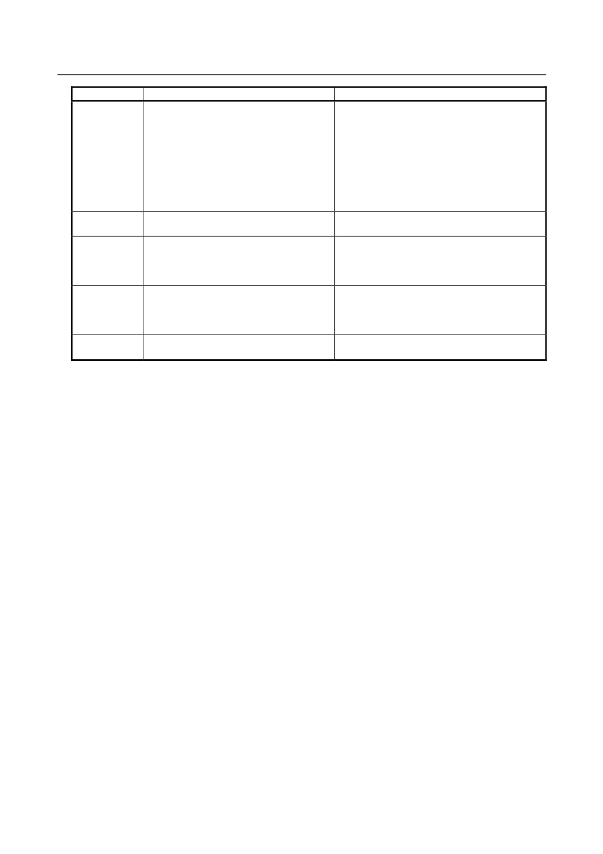
Error number
Log message
Meaning and corrective action
E-0E88
Access is denied
Possible causes are:
9
The specified folder or file to be deleted is
read-only.
9
The specified file to be deleted is open.
9
The specified file to be opened is already
open. (An attempt was made to open an
open file.)
9
A file opened for writing data was read.
9
A file opened for reading data was written.
E-0E8D
Access exceeded the file size
An attempt was made to access an invalid
position for file pointer setting.
E-0F40
Overcurrent occurred
The USB device may be damaged.
If this error occurs, turn the power to the CNC off,
then on again. If this error frequently occurs,
replace the USB device.
E-0F41
Parity Error occurred
The main board may be damaged.
If this error occurs, then the power to the CNC off,
then on again. If this error frequently occurs,
replace the main board.
E-XXXX
(No message)
Internal error.
Contact FANUC with the error number.
- 816 -
ADDITIONAL INFORMATION
Addition and correction of FANUC Series 30i/31i/32i-MODEL B
MAINTENANCE MANUAL
1. Type of applied technical documents
Name
FANUC Series 30i/31i/32i-MODEL B
MAINTENANCE MANUAL
Spec.No. /Version
B-64485EN/01
2. Summary of change
Group
Name / Outline
New, Add,
Applicable
Correct,
Date
Delete
Basic
Function
Optional
Function
Unit
Maintenance
parts
Notice
Correction
-Specifications of each case in Section B.1 and Subsection B.4.2 are
corrected.
-Note of LCD unit in Section B.1 is corrected.
-Item of GUI card in Subsection B.4.2 is corrected.
Another
-Subsection 4.2.9 “Operator's Panel Connection Unit [Supporting
I/O Link i]” is added.
-Operator's panel connection unit is added to Table 6.5.8 (b) in
Subsection 6.5.8, and Section B.6.
TITLE
Addition and correction of
FANUC Series 30i/31i/32i-MODEL B
MAINTENANCE MANUAL
CUST.
01
10.08.23
Miyashita
New issue
DRAW. NO. B-64485EN/01-01
SHEET
Edit.
DATE
Design
Description
1 / 9
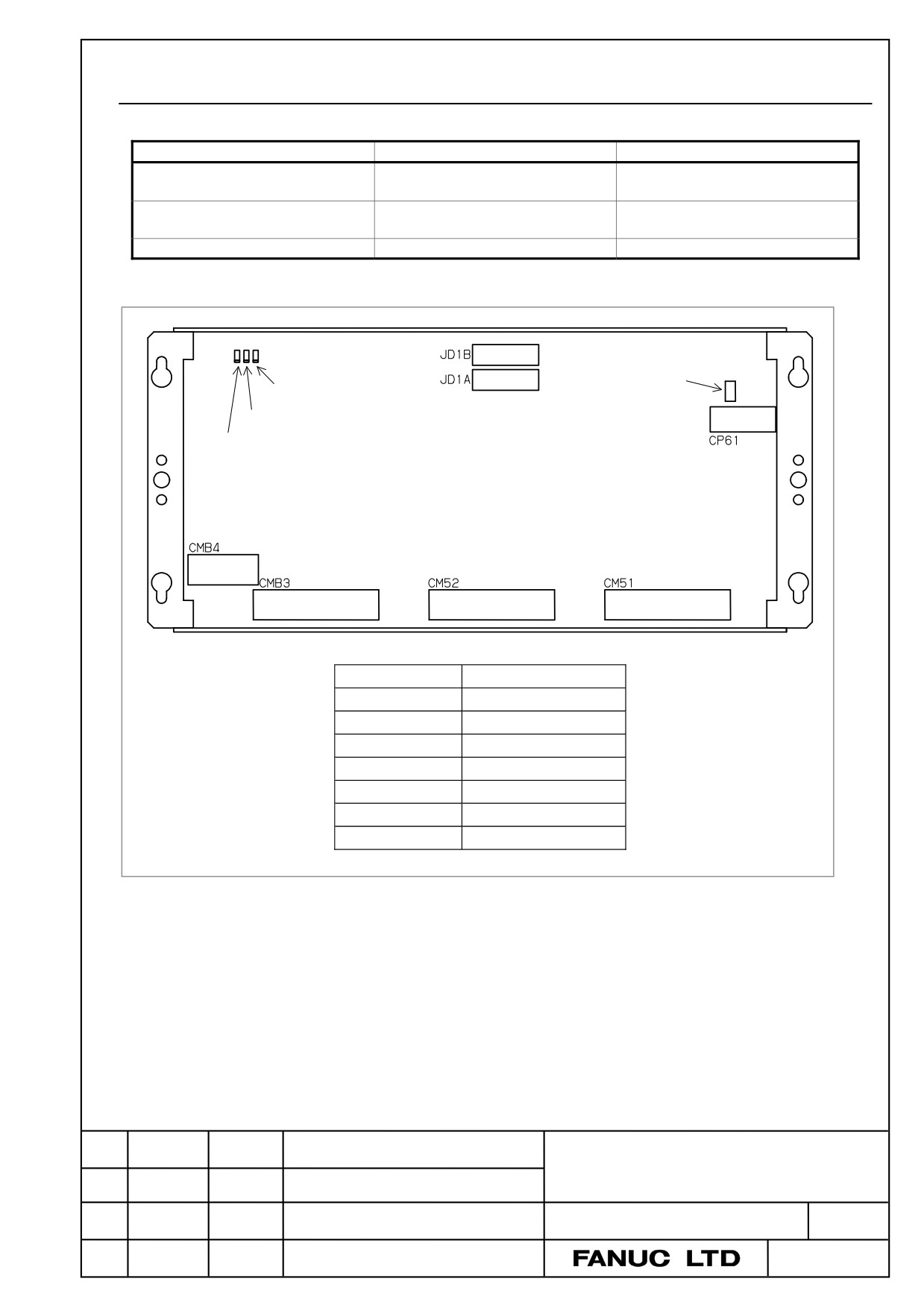
4.2.9
Operator's Panel Connection Unit [Supporting I/O Link i]
- Specifications
Item
Ordering specifications
Specification
Operator's panel connection unit
DI : 96 points
A16B-2204-0260
(source DO)
DO : 64 points
Operator's panel connection unit
DI : 64 points
A16B-2204-0261
(source DO)
DO : 32 points
Fuse (spare parts)
A02B-0163-K111
3.2A
- Connector, LED, and fuse locations
Fuse
FUSE LED (red)
LINK LED (green)
ALM LED (red)
Connector number
Use
JD1A
Second I/O Link i stage
JD1B
First I/O Link i stage
CP61
24VDC input
CM51
DI/DO connector
CM52
DI/DO connector
CMB3
DI/DO connector
CMB4
DI/DO connector
- LED
This printed circuit board incorporates a green LED, “LINK”, and two red LEDs, “ALM” and “FUSE” in
above figure.
See Subsection 4.2.1 for descriptions of the correspondence between the on/off state of each LED and the
status of the operator's panel connection unit.
TITLE
Addition and correction of
FANUC Series 30i/31i/32i-MODEL B
MAINTENANCE MANUAL
CUST.
DRAW. NO. B-64485EN/01-01
Edit.
DATE
Design
Description
SHEET
2 / 9
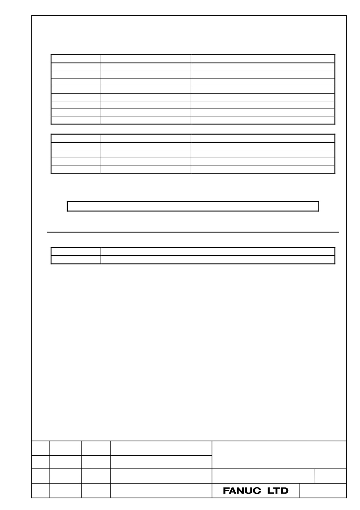
- Correspondence between slot numbers and intra-slot byte addresses
The table below lists the slot number and intra-slot byte address for this unit.
For A16B-2204-0260
Slot number
Alarm information number
Address of the DO driver which detects an error
1
0
Yn1
1
1
Yn1+1
1
2
Yn1+2
1
3
Yn1+3
1
4
Yn1+4
1
5
Yn1+5
1
6
Yn1+6
1
7
Yn1+7
For A16B-2204-0261
Slot number
Alarm information number
Address of the DO driver which detects an error
1
0
Yn1
1
1
Yn1+1
1
2
Yn1+2
1
3
Yn1+3
Operator's panel connection unit is added to Table 6.5.8(b) in Subsection 6.5.8.
6.5.8
Displaying i/o devices connection status ([I/O DEVICE] screen)
Table 6.5.8 (b) Displayed type of I/O Units (for I/O Link i)
ID
Displayed I/O Unit
82
OP. PANEL CONNECTION UNIT
TITLE
Addition and correction of
FANUC Series 30i/31i/32i-MODEL B
MAINTENANCE MANUAL
CUST.
DRAW. NO. B-64485EN/01-01
Edit.
DATE
Design
Description
SHEET
3 / 9